1
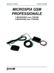
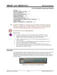
VOLTECHNOTES
IEC60404
Testing with
Constant AC
Current
VPN 104-151/1
VOLTECHNOTES
TESTING TRANSFORMERS AND CORES
WITH C ONSTANT C URRENT
IEC60404
It is a requirement of IEC60404-2 that measurements of core loss are made
under constant ac current test conditions. Ideally, current transformers will
also be tested with constant ac current drive.
Most general-purpose transformer test equipment does not have the ability to
provide a high level of constant ac current drive.
The AT Series transformer testers from Voltech contain a wide variety of
programmable signal sources. These are used to test multiple parameters, at
high speed, on parts ranging from surface-mounting ferrite inductors to steel
laminate transformers of a few kVA.
By following the guidance given in these notes, customers may also configure
the AT3600 to test cores, inductors and transformers under constant ac
current conditions.
Features of Constant Current AC Drive on the AT3600
• Constant current is fully programmable for amplitude and frequency.
• Simultaneous measurement of rms or rectified mean (rms scaled) voltage.
• Current carefully ramped up and down under software control.
• Can use external ac source to extend the VA range.
• Integrates into normal test sequence with all other tests available on an
AT3600 (including HiPot).
Equipment Required
• AT3600.
• AC Interface.
2
• VOCX test. (MAGX is useful during program development.)
© 2003 Voltech Instruments. All rights reserved.
VOLTECHNOTES
C ONSTANT CURRENT
• A current-sensing resistor.
• A step-down power transformer.
Basic Principle
Constant-current ac testing uses the normal VOCX test to control the current
and make the secondary voltage measurement.
• The current to be controlled, I, is converted to a voltage, V, by means of a
current-sensing resistor, R.
• The voltage, V, is connected to the sense terminals of the AT3600, which
would normally be used to measure the energizing voltage.
• In the PC Editor, the voltage, V, is used as the energized voltage.
• When VOCX is performed, the AT3600 will trim the source, such that the
desired current is provided, I = V / R.
• The transformer secondary voltage is measured in the normal way as the
result of the VOCX test.
• The AT3600 adjusts the source voltage to maintain a constant ac current
through resistor, R.
Transformer
Under Test
AC
Interface
R
I=V/ R
AT3600
V
Sense
3
© 2003 Voltech Instruments. All rights reserved.
VOLTECHNOTES
C ONSTANT CURRENT
Connection Diagram
Step-down
Transformer
Secondary
Voltage
Connections
LOW Node
(Sense Only)
HIGH Node
(Sense Only)
Part Under
Test
Current Sense
Resistor, R
Current-Sense Resistor
The resistor is used to convert the current flowing the in part into a voltage
for the AT3600 to measure.
• The voltage produced (V = I x R) should be in the range 10mV to 1V.
• To minimize waveform distortion, the resistor should be less or equal to 1
ohm.
• Check the power consumed (I2R) and choose a suitably rated resistor.
4
© 2003 Voltech Instruments. All rights reserved.
VOLTECHNOTES
C ONSTANT CURRENT
Step-down Transformer
The step-down transformer is used to increase the current capability of the
AT3600, and to better match the voltage across the part to the characteristics of the AT3600 source.
• Ratio should provide required current with good margin.
• VA rating must be greater than VA required to energize the part and the
sense resistor.
• An external ac source may be used to increase the VA rating of the
AT3600's generator.
Worked Example
A laminate core is to be tested in accordance with IEC60404-2. Under a
constant ac current of up to 3A, 1V at 50Hz in the primary test winding, the
secondary voltage is measured and limits are applied in terms of the rectified mean voltage (rms scaled).
Resistor
To produce 100mV at 3A,
R = 100mV / 3A
R = 0.333 Ohm.
Choose 0.5 Ohm standard value.
V = 3A x 0.5 Ohm
V = 1.5V
W = 1.52 x 0.5
W = 1.125
Choose 2W standard part.
Resistor is 0.5 Ohm, 2W. Voltage produced will be 1.5V.
5
© 2003 Voltech Instruments. All rights reserved.
VOLTECHNOTES
C ONSTANT CURRENT
Step-down Transformer
Look for a stock transformer with, say, a 5A secondary current rating. A stock
transformer will usually have a 110 and/or 230V primary.
VA rating is that of the part plus the current sense resistor.
VA = 3A x (1+1.5)V = 7.5VA
Choose a 7.5VA (or greater) transformer with a 5A low-voltage secondary.
Toroidal transformers are ideal, since they will have low losses.
For example:
Primary: 230V Secondary: 2 x 6V @ 2.5A.
The secondaries are connected in parallel to provide a 6V, 5A output.
230V
AC Interface:
'Transformer Drive Output'
6V, 5A
AC Interface:
'Input from External Source'
The step-down transformer will supply the part under test and the currentsense resistor in series. The step-down transformer’s secondary voltage,
Vs, being:
Vs = 1.5V +1V = 2.5V
The AT3600 must supply 2.5 x 230:6 to the primary of the transformer.
2.5 x 230 / 6 = 95.8V
The AT3600 can supply 270V, so 95.8V is well within its capability.
6
© 2003 Voltech Instruments. All rights reserved.
VOLTECHNOTES
C ONSTANT CURRENT
Programming
It is convenient to use the MAGX test at first, since this will confirm that the
desired current is being generated.
In the previous connection diagram, the return or 'low' end of the sense
resistor has been connected to node 5, and the higher voltage end of the
resistor connected to node 3. For optimum accuracy, it is important that the
physical 'low' connection is also designated as the 'low' terminal in the
program.
Next, you must set up the External Source in the Editor. The source type is
'AT Output Transformer', and you are required to enter the nominal turns
ratio of the transformer. Remember that the AT3600 will trim the output
voltage by comparing the desired voltage (from the program) with that
measured across the programmed sense terminals. The ratio is used to
establish a target for voltage ramp-up, when the tester starts the test. Using
7
© 2003 Voltech Instruments. All rights reserved.
VOLTECHNOTES
C ONSTANT CURRENT
the correct ratio will optimize test speed.
In this case, the ratio is modified because, when the desired 1.5V is achieved
across the resistor, the step-down transformer must also supply the 1V across
the part under test. For 1.5V programmed, the step-down transformer delivers
2.5V.
Ratio
= 230:6 x 2.5:1.5
= 63.9:1
That is, for every 1V programmed, the AT3600 must supply 63.9V to the primary
of the step-down transformer.
In the MAGX test, simply enter the required voltage, V, across the resistor to
program the constant current, I. In this case, enter 1.5V.
8
© 2003 Voltech Instruments. All rights reserved.
VOLTECHNOTES
C ONSTANT CURRENT
With an AT3600 connected to the PC Editor and the circuit assembled as shown
previously, you may now press the 'Measure' button to run a MAGX measurement. If the current measured is as desired, then all is well. If not, simply adjust
the program voltage to suit. If the tester should fail to return a result, check the
wiring and settings carefully.
Now secondary connections may be made for VOCX tests. Note that VOCX has
the option to measure rms voltage or "mean sense rms scaled" voltage. For the
mean sense option, the tester measures the rectified mean voltage and multiplies
that by 1.11. This option is offered as a means of comparing the measurements
with those made by mean sensing analog meters and calculated parameters that
require rectified mean.
9
© 2003 Voltech Instruments. All rights reserved.
VOLTECHNOTES
C ONSTANT CURRENT
Conclusions
The versatile AT3600 transformer tester already provides an unrivalled range of
tests for checking the construction and performance of a wide range of coils and
transformers. By following the above guidelines, users can also seamlessly integrate the testing of cores and transformers under constant ac current conditions
into the AT3600 environment, providing high-speed PASS / FAIL testing and
accurate, detailed test results for analysis.
Appendices
Adding Other Tests
To include other tests such as R, simply use extra nodes to connect directly
across the windings in the normal way. You will have to add and extra 'dummy'
winding in the schematic and use those terminal names in the program. Adding
extra tests in this way does not interfere with the operation of the constant current
drive explained here.
Extending the Constant Current Range
To test very high VA transformers, the drive may be extended by using an external ac source. 500VA is available from the AT3600's internal generator.
10
© 2003 Voltech Instruments. All rights reserved.
VOLTECHNOTES
C ONSTANT CURRENT
Cautions
• Always observe the health and safety precautions stated in the latest issue of
the Voltech AT3600 user manual.
• Do NOT connect the power and sense nodes of the energized voltage together
for the constant current circuit. With prolonged use, you may damage protection devices inside the AT3600.
• Use properly rated and sound connections. Under normal conditions, the
AT3600 will safely ramp current up and down. If connections are undone during
the middle of a test, dangerous voltages may be generated by the part under
test.
The Voltech AT3600 and ATi
Automatic Transformer Testers
© 2003 Voltech Instruments. All rights reserved.
11
VOLTECHNOTES
Voltech Instruments Ltd.
148 Sixth Street
Harwell International Business Centre
Harwell, Didcot, Oxon OX11 ORA
U.K.
Telephone: +44 (0)1235 834555
Facsimile: +44 (0)1235 835016
E-mail: [email protected]
Voltech Instruments Inc.
11637 Kelly Road, Suite 306
Fort Myers, FL 33908
U.S.A.
Telephone: +1 239 437 0494
Facsimile: +1 239 437 3841
E-mail: [email protected]
www.voltech.com
Note: While every care has been taken in compiling the information for this publication, Voltech Instruments cannot accept legal liability for any inaccuracies. Voltech Instruments reserves the right to alter product specifications without notice and whenever necessary
to ensure optimum performance from its product range.
VPN 104-151/1