1
EXOR International
Industrial Computing Solutions
Fan-less Computer
eCC3600E Series
User Manual
www.exorint.net
Content
CONTENTS
Preface
Chapter 2: Jumpers and Connectors
Copyright ............................................................................................. iv
Disclaimer .............................................................................................. iv
Acknowledgements ............................................................................... iv
Regulatory Compliance Statements ........................................................ iv
Declaration of Conformity...................................................................... iv
RoHS Compliance ................................................................................... v
Warranty and RMA ................................................................................ vi
Safety Information ................................................................................viii
Installation Recommendations...............................................................viii
Safety Precautions.................................................................................. ix
Technical Support and Assistance ............................................................ x
Conventions Used in this Manual ............................................................ x
Global Service Contact Information ........................................................ xi
Package Contents .................................................................................xiii
Ordering Information ............................................................................xiv
Before You Begin ....................................................................................8
Precautions ............................................................................................8
Jumper Settings ......................................................................................9
Locations of the Jumpers and Connectors for NISB 3600.......................10
NISB 3600 .........................................................................................10
Jumpers ................................................................................................12
CMOS Clear Select ............................................................................12
ME Pin Header...................................................................................12
LVDS Power Pin Header .....................................................................13
Connector Pin Definitions .....................................................................14
External I/O Interfaces - Front Panel ...................................................14
USB 3.0..........................................................................................14
DisplayPort A .................................................................................14
DisplayPort B ..................................................................................15
CompactFlash ................................................................................15
SIM Card Connector ......................................................................16
Power Switch .................................................................................16
External I/O Interfaces - Rear Panel.....................................................17
Remote Power on/off Switch ..........................................................17
DC-in Power Jack ...........................................................................17
Serial Interface (COM 1 - COM 4)...................................................18
COM 5 and COM 6 Ports ...............................................................20
LAN1 and USB 3.0 Ports .................................................................20
LAN2 and USB 2.0 Ports .................................................................21
Chapter 1: Product Introduction
Overview ................................................................................................1
Key Features ...........................................................................................1
Hardware Specifications ..........................................................................2
Knowing Your eCC3600E .......................................................................4
Front Panel ..........................................................................................4
Rear Panel ...........................................................................................5
Mechanical Dimensions...........................................................................6
Copyright © 2014 EXOR International S.p.A. All Rights Reserved.
ii
eCC3600E Series User Manual
Content
VGA and DVI-D Connectors ...........................................................22
Audio Connectors ..........................................................................23
Internal Connectors ...........................................................................24
SIM Card Line-out Pin Header ........................................................24
SIM Card Mic-in Pin Header ...........................................................24
DC-in Power Connector .................................................................25
LVDS Channel A Connector ............................................................25
LVDS Channel B Connector ............................................................26
LVDS Backlight Connector ..............................................................26
Line-in 1 Pin Header .......................................................................27
Line-in 2 Pin Header .......................................................................27
SATA1 Connector...........................................................................28
SATA2 Connector...........................................................................28
SATA3 Connector...........................................................................29
SATA1 Power Connector ................................................................29
SATA2 Power Connector ................................................................30
SATA3 Power Connector ................................................................30
GPS JST Connector.........................................................................31
USB 2.0 JST Connector...................................................................31
PCIe x8 Slot....................................................................................32
COM4 RI# Pin Header ....................................................................33
Mini-PCIe Connector ......................................................................34
GPIO Pin Header ............................................................................35
GPIO LED Pin Header......................................................................35
Smart Fan1 Connector ...................................................................36
Smart Fan2 Connector ...................................................................36
Internal LED Pin Header ..................................................................37
Reset JST Connector.......................................................................37
Installing a SATA DOM ..........................................................................42
Installing a PCIe/PCI Expansion Card......................................................44
Removing the Chassis Top Cover ...........................................................46
Installing a CPU.....................................................................................46
Installing a SO DIMM ............................................................................48
Installing a Wireless LAN Module (half-size) ........................................49
Installing a Wireless LAN Module (full-size) ........................................50
Installing a GPS Module ........................................................................51
Installing Antennas ...............................................................................53
Installing a SIM Card .............................................................................54
Installing a CompactFlash Card .............................................................55
Wallmount Brackets ..............................................................................56
Chapter 4: BIOS Setup
About BIOS Setup .................................................................................57
When to Configure the BIOS.................................................................57
Default Configuration ...........................................................................58
Entering Setup ......................................................................................58
Legends ................................................................................................58
BIOS Setup Utility ..................................................................................60
Main .................................................................................................60
Advanced .........................................................................................61
Chipset..............................................................................................71
Boot ..................................................................................................80
Security .............................................................................................82
Save & Exit ........................................................................................82
Appendix A: Power Consumption.........................83
Chapter 3: System Setup
Appendix B: GPI/O Programming Guide...............85
Removing the Chassis Bottom Cover ....................................................38
Installing a SATA Hard Drive ..................................................................39
Copyright © 2014 EXOR International S.p.A. All Rights Reserved.
Appendix C: Watchdog Timer Setting...................87
iii
eCC3600E Series User Manual
Preface
PREFACE
Copyright
Regulatory Compliance Statements
This publication, including all photographs, illustrations and software, is
protected under international copyright laws, with all rights reserved. No
part of this manual may be reproduced, copied, translated or transmitted
in any form or by any means without the prior written consent from EXOR
International S.p.A.
This section describes how to keep the system CE compliant.
Declaration of Conformity
CE
The product(s) described in this manual complies with all applicable
European Union (CE) directives if it has a CE marking. For computer systems
to remain CE compliant, only CE-compliant parts may be used. Maintaining
CE compliance also requires proper cable and cabling techniques.
Disclaimer
The information in this document is subject to change without prior notice
and does not represent commitment from EXOR International S.p.A. However,
users may update their knowledge of any product in use by constantly checking
its manual posted on our website: http://www.exorint.net. EXOR shall not be
liable for direct, indirect, special, incidental, or consequential damages arising
out of the use of any product, nor for any infringements upon the rights
of third parties, which may result from such use. Any implied warranties of
merchantability or fitness for any particular purpose is also disclaimed.
Acknowledgements
eCC3600E Series is a trademark of EXOR International S.p.A. All other
product names mentioned herein are registered trademarks of their
respective owners.
Copyright © 2014 EXOR International S.p.A. All Rights Reserved.
iv
eCC3600E Series User Manual
Preface
RoHS Compliance
How to recognize EXOR RoHS Products?
EXOR RoHS Environmental Policy and Status
Update
All new product models launched after January 2006 will be RoHS compliant.
They will use the usual EXOR naming convention.
This publication, including all photographs, illustrations
and software, is protected under international copyright
laws, with all rights reserved. No part of this manual
may be reproduced, copied, translated or transmitted in any form or by any
means without the prior written consent from EXOR International S.p.A.
RoHS restricts the use of Lead (Pb) < 0.1% or 1,000ppm, Mercury (Hg) < 0.1%
or 1,000ppm, Cadmium (Cd) < 0.01% or 100ppm, Hexavalent Chromium
(Cr6+) < 0.1% or 1,000ppm, Polybrominated biphenyls (PBB) < 0.1% or
1,000ppm, and Polybrominated diphenyl Ethers (PBDE) < 0.1% or 1,000ppm.
In order to meet the RoHS compliant directives, EXOR has established an
engineering and manufacturing task force to implement the introduction
of green products. The task force will ensure that we follow the standard
EXOR development procedure and that all the new RoHS components and
new manufacturing processes maintain the highest industry quality levels
for which EXOR are renowned.
The model selection criteria will be based on market demand. Vendors and
suppliers will ensure that all designed components will be RoHS compliant.
Copyright © 2014 EXOR International S.p.A. All Rights Reserved.
v
eCC3600E Series User Manual
Preface
Warranty and RMA
EXOR Warranty Period
Repair Service Charges for Out-of-Warranty Products
EXOR manufactures products that are new or equivalent to new in
accordance with industry standard. EXOR warrants that products will be
free from defect in material and workmanship for 2 years, beginning on
the date of invoice by EXOR. HCP series products (Blade Server) which are
manufactured by EXOR are covered by a three year warranty period.
EXOR will charge for out-of-warranty products in two categories, one is
basic diagnostic fee and another is component (product) fee.
Repair Service Charges for Out-of-Warranty Products
EXOR will charge for out-of-warranty products in two categories, one is
basic diagnostic fee and another is component (product) fee.
NEXCOM Return Merchandise Authorization (RMA)
▪ Customers shall enclose the “EXOR RMA Service Form” with the returned
packages.
System Level
▪ Component fee: EXOR will only charge for main components such as
SMD chip, BGA chip, etc. Passive components will be repaired for free,
ex: resistor, capacitor.
▪ Customers must collect all the information about the problems
encountered and note anything abnormal or, print out any on-screen
messages, and describe the problems on the “EXOR RMA Service Form”
for the RMA number apply process.
▪ Items will be replaced with EXOR products if the original one cannot be
repaired. Ex: motherboard, power supply, etc.
▪ Customers can send back the faulty products with or without accessories
(manuals, cable, etc.) and any components from the card, such as CPU
and RAM. If the components were suspected as part of the problems,
please note clearly which components are included. Otherwise, EXOR is
not responsible for the devices/parts.
▪ Replace with 3rd party products if needed.
▪ If RMA goods can not be repaired, EXOR will return it to the customer
without any charge.
Board Level
▪ Customers are responsible for the safe packaging of defective products,
making sure it is durable enough to be resistant against further damage
and deterioration during transportation. In case of damages occurred
during transportation, the repair is treated as “Out of Warranty.”
▪ Component fee: EXOR will only charge for main components, such as
SMD chip, BGA chip, etc. Passive components will be repaired for free,
ex: resistors, capacitors.
▪ If RMA goods can not be repaired, EXOR will return it to the customer
without any charge.
▪ Any products returned by EXOR to other locations besides the customers’
site will bear an extra charge and will be billed to the customer.
Copyright © 2014 EXOR International S.p.A. All Rights Reserved.
vi
eCC3600E Series User Manual
Preface
Warnings
Read and adhere to all warnings, cautions, and notices in this guide and
the documentation supplied with the chassis, power supply, and accessory
modules. If the instructions for the chassis and power supply are inconsistent
with these instructions or the instructions for accessory modules, contact
the supplier to find out how you can ensure that your computer meets
safety and regulatory requirements.
Cautions
Electrostatic discharge (ESD) can damage system components. Do the
described procedures only at an ESD workstation. If no such station is
available, you can provide some ESD protection by wearing an antistatic
wrist strap and attaching it to a metal part of the computer chassis.
Copyright © 2014 EXOR International S.p.A. All Rights Reserved.
vii
eCC3600E Series User Manual
Preface
Safety Information
Installation Recommendations
Before installing and using the device, note the following precautions:
Ensure you have a stable, clean working environment. Dust and dirt can get
into components and cause a malfunction. Use containers to keep small
components separated.
▪ Read all instructions carefully.
▪ Do not place the unit on an unstable surface, cart, or stand.
▪ Follow all warnings and cautions in this manual.
Adequate lighting and proper tools can prevent you from accidentally
damaging the internal components. Most of the procedures that follow
require only a few simple tools, including the following:
▪ When replacing parts, ensure that your service technician uses parts
specified by the manufacturer.
▪ A Philips screwdriver
▪ A flat-tipped screwdriver
▪ Avoid using the system near water, in direct sunlight, or near a heating
device.
▪ A grounding strap
▪ The load of the system unit does not solely rely for support from the
rackmounts located on the sides. Firm support from the bottom is highly
necessary in order to provide balance stability.
▪ An anti-static pad
Using your fingers can disconnect most of the connections. It is recommended
that you do not use needle-nose pliers to disconnect connections as these
can damage the soft metal or plastic parts of the connectors.
▪ The computer is provided with a battery-powered real-time clock circuit.
There is a danger of explosion if battery is incorrectly replaced. Replace
only with the same or equivalent type recommended by the manufacturer.
Discard used batteries according to the manufacturer’s instructions.
CAUTION!
CAUT
CA
UTION!
UTIO
UT
ION!
ION!
Danger of explosion if battery is incorrectly replaced.
Replace with the same or equivalent type recommended by
the manufacturer. Discard used batteries according to the
manufacturer’s instructions.
Copyright © 2014 EXOR International S.p.A. All Rights Reserved.
viii
eCC3600E Series User Manual
Preface
Safety Precautions
11. If the equipment is not used for a long time, disconnect it from the
power source to avoid damage by transient overvoltage.
1. Read these safety instructions carefully.
2. Keep this User Manual for later reference.
12. Never pour any liquid into an opening. This may cause fire or electrical
shock.
3. Disconnect this equipment from any AC outlet before cleaning. Use a
damp cloth. Do not use liquid or spray detergents for cleaning.
13. Never open the equipment. For safety reasons, the equipment should be
opened only by qualified service personnel.
4. For plug-in equipment, the power outlet socket must be located near the
equipment and must be easily accessible.
14. If one of the following situations arises, get the equipment checked by
service personnel:
a. The power cord or plug is damaged.
b. Liquid has penetrated into the equipment.
c. The equipment has been exposed to moisture.
d. The equipment does not work well, or you cannot get it to work
according to the user’s manual.
e. The equipment has been dropped and damaged.
f. The equipment has obvious signs of breakage.
5. Keep this equipment away from humidity.
6. Put this equipment on a stable surface during installation. Dropping it or
letting it fall may cause damage.
7. The openings on the enclosure are for air convection to protect the
equipment from overheating. DO NOT COVER THE OPENINGS.
15. Do not place heavy objects on the equipment.
8. Make sure the voltage of the power source is correct before connecting
the equipment to the power outlet.
16. The unit uses a three-wire ground cable which is equipped with a third
pin to ground the unit and prevent electric shock. Do not defeat the
purpose of this pin. If your outlet does not support this kind of plug,
contact your electrician to replace your obsolete outlet.
9. Place the power cord in a way so that people will not step on it. Do not
place anything on top of the power cord. Use a power cord that has been
approved for use with the product and that it matches the voltage and
current marked on the product’s electrical range label. The voltage and
current rating of the cord must be greater than the voltage and current
rating marked on the product.
17. CAUTION: DANGER OF EXPLOSION IF BATTERY IS INCORRECTLY
REPLACED. REPLACE ONLY WITH THE SAME OR EQUIVALENT TYPE
RECOMMENDED BY THE MANUFACTURER. DISCARD USED BATTERIES
ACCORDING TO THE MANUFACTURER’S INSTRUCTIONS.
10. All cautions and warnings on the equipment should be noted.
Copyright © 2014 EXOR International S.p.A. All Rights Reserved.
ix
eCC3600E Series User Manual
Preface
Technical Support and Assistance
Conventions Used in this Manual
1. For the most updated information of EXOR products, visit EXOR’s website
at www.exorint.net.
Warning:
Information about certain situations, which if not observed,
can cause personal injury. This will prevent injury to yourself
when performing a task.
2. For technical issues that require contacting our technical support team or
sales representative, please have the following information ready before
calling:
– Product name and serial number
– Detailed information of the peripheral devices
– Detailed information of the installed software (operating system,
version, application software, etc.)
– A complete description of the problem
– The exact wordings of the error messages
CAUTION!
CAUT
CA
UTIO
UT
ION!
ION!
Caution:
Information to avoid damaging components or losing data.
Note:
Provides additional information to complete a task easily.
Warning!
1. Handling the unit: carry the unit with both hands and handle it with care.
Safety Warning: This equipment is intended for installation
in a Restricted Access Location only.
2. Maintenance: to keep the unit clean, use only approved cleaning products
or clean with a dry cloth.
3. CompactFlash: Turn off the unit’s power before inserting or removing a
CompactFlash storage card.
Copyright © 2014 EXOR International S.p.A. All Rights Reserved.
x
eCC3600E Series User Manual
Preface
Package Contents
Before continuing, verify that the NISE 3600E package that you received is complete. Your package should have all the items listed in the following table.
Item
1
2
3
4
5
6
7
8
9
10
11
Description
Terminal Blocks 2P Phoenix Contact:1803578
Round Head Screw W/Spring+Flat Washer Long FEI:P3x6L
Flat Head Screw Long FEI:F#6-32x8
I Head Screw Long FEI:I2x4 NYLOK NIGP
Round Head Screw Long FEI:P6#32T T10 NYLOK
Flat Head Screw Long FEI:F3x5 NYLOK NI+Heat Treatment
Plastic Screw
Plastic Nut GIN LIAN:M6HW
Thermal Pad APUS:3A2015001001500
Cable EDI:231441090251-RS
DC Cord EDI:281040051051-RS
Copyright © 2014 EXOR International S.p.A. All Rights Reserved.
Qty
2
2
1
2
1
4
1
1
1
1
1
xi
eCC3600E Series User Manual
Preface
Ordering Information
The following information below provides ordering information for eCC3600E Series.
• Barebone
eCC3600E (P/N: 70ECC3600E)
- 3rd Generation Intel® Core™ i5/i3 Fanless System with one PCIe x4 Expansion
eCC3600P2E (P/N: 70ECC3600P2E)
- 3rd Generation Intel® Core™ i5/i3 Fanless System with one PCIe x4 Expansion
and one PCI Expansion
Optional Power Adapter: Suggest to use an appropriate AC/DC
power adapter compliant with CE or UL safety regulations.
Copyright © 2014 EXOR International S.p.A. All Rights Reserved.
xii
eCC3600E Series User Manual
Chapter 1: Product Introduction
CHAPTER 1: PRODUCT INTRODUCTION
Overview
Key Features
▪ 4x USB 3.0, 2x USB 2.0, 5x RS232 and 1x RS232/422/485
▪ Support 3rd generation Intel® Core™ i5/ i3 rPGA socket type processor
▪ 1x internal mini-PCIe with two antenna holes
▪ Mobile Intel® QM77 PCH
▪ 1x PCIex4 Expansion and 1x external CFast socket
▪ Support 1x 2.5” SATA HDD or 2x SATA DOM
▪ Support 9V~30V DC input
▪ 1x VGA, 1x DVI-D and 2x Display port with Independent Display support
▪ Support ATX power mode, WoL, LAN teaming and PXE function
▪ Dual Intel® GbE LAN ports
Copyright © 2014 EXOR International S.p.A. All Rights Reserved.
1
eCC3600E Series User Manual
Chapter 1: Product Introduction
Hardware Specifications
CPU Support
I/O Interface-Front
▪ Support 3rd generation Intel® Core™ i5/i3 rPGA Socket Type Processor
- Core™ i5-3610ME, Dual Core, 2.7GHz, 3M Cache
- Core™ i3-3120ME, Dual Core, 2.4GHz, 3M Cache
- Support Three Independent Display with above processors
▪ Support 2nd generation Intel® Core™ i5/i3 rPGA Socket Type Processor
- Core™ i5-2510E, Dual Core, 2.5GHz, 3M Cache
- Core™ i3-2330E 2.2GHz, 3M Cache
- Celeron® B810, Dual Core, 1.6GHz, 2M Cache
- Support Dual Independent Display with above processors
▪
▪
▪
▪
▪
▪
▪
ATX power on/ off switch
HDD Access/ Power status LEDs
2x USB3.0 ports (Blue Color)
2x Display Port (Can be converted to DVI-D or HDMI via cables)
2x Antenna holes
1x external CFast (optional)
1x SIM card socket
I/O Interface-Rear
Main Memory
▪ 2x DB9 for COM5 & COM6 (RS232)
▪ 1x DB44 Serial Port, 4x COM port
- COM1/COM3/COM4: RS232
- COM2: RS232/422/485
▪ 2x Intel® GbE LAN ports (Intel 82574L and 82579LM)
▪ 2x USB2.0 ports
▪ 2x USB3.0 ports (Blue Color)
▪ 1x DB15 VGA port
▪ 1x DVI-D port
▪ 1x Line-out and 1x Mic-in
▪ 2-pin Remote Power on/ off switch
▪ 9~30V DC input
▪ 2x DDR3 SO-DIMM socket, supports up to 8GB DDR3/ DDR3L 1333/
1600 SDRAM, with un-buffered and non-ECC
Display Option
▪ Three Independent Display (only support on 3rd Generation Processor)
- Two Display Port and 1x VGA
- Two Display Port and 1x DVI-D
▪ Dual Independent Display
- VGA and DVI-D
- Display Port and VGA
- Display Port and DVI-D
Copyright © 2014 EXOR International S.p.A. All Rights Reserved.
2
eCC3600E Series User Manual
Chapter 1: Product Introduction
Storage Device
Construction
▪ 1x CFast socket
▪ 1x 2.5” SATA HDD or 2x SATA DOM
▪ SATA DOM: support 90 degree horizontal type only
▪ Aluminum Chassis with fanless design
Environment
▪ Operating temperature:
Ambient with air flow: -5°C ~ 55°C
(According to IEC60068-2-1, IEC60068-2-2, IEC60068-2-14)
▪ Storage temperature: -20°C ~ 80°C
▪ Relative humidity: 95% at 40 degree C
▪ Shock protection: 20G, half sine, 11ms, IEC60068-2-27
▪ Vibration protection
Random: 0.5Grms @5~500 Hz according to IEC60068-2-64
Sinusoidal: 0.5Grms @5~500 Hz according to IEC60068-2-6
Expansion Slot
▪ 1x miniPCIe socket (support optional WiFi or 3.5G module)
▪ eCC3600E: one PCIe x4 Expansion Slot
– Add-on card length: 169mm max.
– Power consumption: 10W/slot max.
▪ eCC3600P2E: one PCIe x4 Expansion and one PCI Expansion
– Add-on card length: 169mm max./PCIex4 expansion and 240mm
max./PCI expansion
– Power consumption: 10W/slot max.
Certifications
Power Requirements
▪ CE approval
▪ ATX power mode
▪ On-board DC to DC power support from 9V to 30V DC
▪ Optional power adapter
Dimensions
eCC3600E
▪ 215mm (W) x 272mm (D) x 93mm (H) without wall mount bracket
eCC3600P2E
▪ 215mm (W) x 272mm (D) x 114mm (H) without wall mount bracket
Copyright © 2014 EXOR International S.p.A. All Rights Reserved.
3
eCC3600E Series User Manual
Chapter 1: Product Introduction
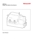
Knowing Your eCC3600E
USB 3.0
Dual USB 3.0 ports to connect the system with USB 3.0/2.0 devices.
Front Panel
Antenna Hole
Used to install external antennas.
Antenna hole
Power Switch
Display Ports
Dual DisplayPort to connect the system with display devices.
SIM
Used to insert a SIM card.
CFast Socket
Used to insert a CompactFlash card.
Power/HDD/LAN LED
Indicates the power status, hard drive and LAN activity of the system.
Power Switch
Press to power-on or power-off the system.
SIM Card
USB 3.0
Display Port
Copyright © 2014 EXOR International S.p.A. All Rights Reserved.
CFast
Power/HDD/LAN LEDs
4
eCC3600E Series User Manual
Chapter 1: Product Introduction
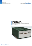
Rear Panel
9-30V DC Input
COM5-COM6: RS232
Digital Output
Used to plug a DC power cord.
VGA
COM5 and COM6
LAN
Two DB9 ports used to connect RS232 compatible devices.
COM1 to COM4
The DB44 port supports three RS232 and one RS232/422/485 compatible
serial devices.
LAN
Line-out
Used to connect the system to a local area network.
Mic-in
USB 3.0
Used to connect USB 3.0/2.0 devices.
9-30V DC Input
Remote power on/off
USB 2.0
USB 3.0
Used to connect USB 2.0/1.1 devices.
USB 2.0
COM1-COM4
DVI-D
COM1&3&4: RS232
VGA
COM2: RS232/422/485
Used to connect an analog VGA monitor.
DVI-D
Remote Power On/Off
Used to connect a digital LCD panel.
Used to connect a remote to power on/off the system.
Line-out
Digital Output
Used to connect a headphone or a speaker.
Support S3 Wake on LAN.
Mic-in
Used to connect an external microphone.
Copyright © 2014 EXOR International S.p.A. All Rights Reserved.
5
eCC3600E Series User Manual
Chapter 1: Product Introduction
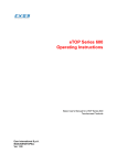
Mechanical Dimensions
270.00
264.00
234.00
204.00
68.00
eCC3600E
214.66
224.68
236.68
Copyright © 2014 EXOR International S.p.A. All Rights Reserved.
6
92.73
100.73
eCC3600E Series User Manual
Chapter 1: Product Introduction
272.00
264.00
234.00
204.00
68.00
eCC3600P2E
214.98
224.68
236.68
Copyright © 2014 EXOR International S.p.A. All Rights Reserved.
7
113.73
119.73
eCC3600E Series User Manual
Chapter 2: Jumpers and Connectors
CHAPTER 2: JUMPERS AND CONNECTORS
This chapter describes how to set the jumpers and connectors on the
eCC3600E motherboard.
dry environments. A grounding strap is warranted whenever danger of
static electricity exists.
Before You Begin
Precautions
▪ Ensure you have a stable, clean working environment. Dust and dirt can
get into components and cause a malfunction. Use containers to keep
small components separated.
Computer components and electronic circuit boards can be damaged by
discharges of static electricity. Working on computers that are still connected
to a power supply can be extremely dangerous.
▪ Adequate lighting and proper tools can prevent you from accidentally
damaging the internal components. Most of the procedures that follow
require only a few simple tools, including the following:
– A Philips screwdriver
– A flat-tipped screwdriver
– A set of jewelers screwdrivers
– A grounding strap
– An anti-static pad
Follow the guidelines below to avoid damage to your computer or yourself:
▪ Always disconnect the unit from the power outlet whenever you are
working inside the case.
▪ If possible, wear a grounded wrist strap when you are working inside the
computer case. Alternatively, discharge any static electricity by touching
the bare metal chassis of the unit case, or the bare metal body of any
other grounded appliance.
▪ Using your fingers can disconnect most of the connections. It is
recommended that you do not use needle-nosed pliers to disconnect
connections as these can damage the soft metal or plastic parts of the
connectors.
▪ Hold electronic circuit boards by the edges only. Do not touch the
components on the board unless it is necessary to do so. Don’t flex or
stress the circuit board.
▪ Before working on internal components, make sure that the power is off.
Ground yourself before touching any internal components, by touching
a metal object. Static electricity can damage many of the electronic
components. Humid environments tend to have less static electricity than
Copyright © 2014 EXOR International S.p.A. All Rights Reserved.
▪ Leave all components inside the static-proof packaging that they shipped
with until they are ready for installation.
▪ Use correct screws and do not over tighten screws.
8
eCC3600E Series User Manual
Chapter 2: Jumpers and Connectors
Jumper Settings
A jumper is the simplest kind of electric switch. It consists of two metal
pins and a cap. When setting the jumpers, ensure that the jumper caps are
placed on the correct pins. When the jumper cap is placed on both pins, the
jumper is short. If you remove the jumper cap, or place the jumper cap on
just one pin, the jumper is open.
Refer to the illustrations below for examples of what the 2-pin and 3-pin
jumpers look like when they are short (on) and open (off).
Two-Pin Jumpers: Open (Left) and Short (Right)
Three-Pin Jumpers: Pins 1 and 2 are Short
3
3
2
2
1
1
Copyright © 2014 EXOR International S.p.A. All Rights Reserved.
9
eCC3600E Series User Manual
Chapter 2: Jumpers and Connectors
Locations of the Jumpers and Connectors for NISB 3600
NISB 3600
The figure below is the top view of the NISB 3600 main board which is the main board used in the eCC3600E system. It shows the locations of the jumpers
and connectors.
SW1
J2
J1
FAN1
CON1
CN1
J3
J4
CN2
JP1
JP3
CN3
JP2
CON2
J7
CON3
J8
CN16
CN6
JP4
CN15
J10
JP5
CN14
USB1
CN8
CN9
Copyright © 2014 EXOR International S.p.A. All Rights Reserved.
JP11 JP10
JP6
J11
JP9 JP8
10
FAN2
eCC3600E Series User Manual
Chapter 2: Jumpers and Connectors
The figure below is the bottom view of the NISB 3600 main board.
SLOT1
CN11 J13 CN10
CN13
J12
CN12
IDE1
Copyright © 2014 EXOR International S.p.A. All Rights Reserved.
11
eCC3600E Series User Manual
Chapter 2: Jumpers and Connectors
Jumpers
CMOS Clear Select
ME Pin Header
Connector type: 1x3 3-pin header, 2.54mm pitch
Connector location: JP4
Connector type: 1x3 3-pin header, 2.54mm
Connector location: JP5
1
3
Pin
1-2 On
2-3 On
1
Settings
Normal
Clear BIOS
3
Pin
1
2
3
1-2 On: default
Definition
SRTC_RST#_PU
SRTC_RST#
CLR_ME
1-2 On: default
Pin
1
2
3
Definition
RTC_RST#_PU
RTC_RST#
CLR_CMOS
Copyright © 2014 EXOR International S.p.A. All Rights Reserved.
12
eCC3600E Series User Manual
Chapter 2: Jumpers and Connectors
LVDS Power Pin Header
Connector type: 1x3 3-pin header, 2.54mm
Connector location: JP6
1
3
Pin
1
2
3
Definition
VCC3
VCCLCDIN
VCC5
1-2 On: default
Copyright © 2014 EXOR International S.p.A. All Rights Reserved.
13
eCC3600E Series User Manual
Chapter 2: Jumpers and Connectors
Connector Pin Definitions
DisplayPort A
External I/O Interfaces - Front Panel
Connector type: DisplayPort
Connector location: J10
USB 3.0
Connector type: Dual USB 3.0 ports
Connector location: USB1
19
20
1
10
9
5
18
14
Pin
1
3
5
7
9
11
13
15
17
MH1
MH3
2
1
4
13
Definition
VCC5
USB2_2P
USB3_RX2_N
GND
USB3_TX2_P
USB2_3N
GND
USB3_RX3_P
USB3_TX3_N
GND
GND
Pin
2
4
6
8
10
12
14
16
18
MH2
MH4
Pin
1
3
5
7
9
11
13
15
17
19
MH1
MH3
Definition
USB2_2N
GND
USB3_RX2_P
USB3_TX2_N
VCC5
USB2_3P
USB3_RX3_N
GND
USB3_TX3_P
GND
GND
Definition
DPC_LANE0_P
DPC_LANE0_N
GND
DPC_LANE2_P
DPC_LANE2_N
GND
DPC_CONFIG1
DPC_AUX_P
DPC_AUX_N
GND
GND
GND
Pin
2
4
6
8
10
12
14
16
18
20
MH2
MH4
Definition
GND
DPC_LANE1_P
DPC_LANE1_N
GND
DPC_LANE3_P
DPC_LANE3_N
DPC_CONFIG2
GND
DPC_HPD
VCC3
GND
GND
While using DisplayPort to HDMI cable or DisplayPort to DVI
cable, the cable must be active type.
Copyright © 2014 EXOR International S.p.A. All Rights Reserved.
14
eCC3600E Series User Manual
Chapter 2: Jumpers and Connectors
DisplayPort B
CompactFlash
Connector type: DisplayPort
Connector location: J8
Connector type: CompactFlash Type 2
Connector location: CN3
19
20
Pin
1
3
5
7
9
11
13
15
17
19
MH1
MH3
2
1
Definition
DPD_LANE0_P
DPD_LANE0_N
GND
DPD_LANE2_P
DPD_LANE2_N
GND
DPD_CONFIG1
DPD_AUX_P
DPD_AUX_N
GND
GND
GND
Pin
2
4
6
8
10
12
14
16
18
20
MH2
MH4
Definition
GND
DPD_LANE1_P
DPD_LANE1_N
GND
DPD_LANE3_P
DPD_LANE3_N
DPD_CONFIG2
GND
DPD_HPD
VCC3
GND
GND
S1
Pin
S1
S2
S3
S4
S5
S6
S7
PC1
PC2
PC3
PC4
PC5
While using DisplayPort to HDMI cable or DisplayPort to DVI
cable, the cable must be active type.
Copyright © 2014 EXOR International S.p.A. All Rights Reserved.
15
S7 PC1
PC17
Definition
GND
SATA_TXP3
SATA_TXN3
GND
SATA_RXN3
SATA_RXP3
GND
CFAST_CDI
GND
NC
NC
NC
Pin
PC6
PC7
PC8
PC9
PC10
PC11
PC12
PC13
PC14
PC15
PC16
PC17
Definition
NC
GND
CFAST_LED1_C
CFAST_LED2_C
NC
NC
NC
VCC3
VCC3
GND
GND
CFAST_CDO
eCC3600E Series User Manual
Chapter 2: Jumpers and Connectors
SIM Card Connector
Power Switch
Connector location: IDE1
Connector location: SW1
C3
C2
C1
C7
C6
C5
Pin
C1
C3
C6
SW
Definition
UIM_PWR
UIM_CLK
UIM_VPP
GND
Copyright © 2014 EXOR International S.p.A. All Rights Reserved.
Pin
C2
C5
C7
Pin
1
3
A1
MH1
Definition
UIM_RESET
GND
UIM_DATA
16
Definition
GND
PBT_PU
PWRLED_N
NC
Pin
2
4
C1
MH2
Definition
PBT_PU
GND
PWRLED_P
NC
eCC3600E Series User Manual
Chapter 2: Jumpers and Connectors
External I/O Interfaces - Rear Panel
DC-in Power Jack
Remote Power on/off Switch
Connector type: 4-pin DC Jack
Connector location: CN1
Connector type: 4-pin switch
Connector location: J2
4
3
1
1
2
3
4
2
Pin
1
3
Definition
GND
SLP_S3#
Copyright © 2014 EXOR International S.p.A. All Rights Reserved.
Pin
2
4
Pin
1
3
5
MH2
MH4
Definition
PBT_PU
GND
17
Definition
VIN
GND
GND
GND
GND
Pin
2
4
MH1
MH3
Definition
VIN
GND
GND
GND
eCC3600E Series User Manual
Chapter 2: Jumpers and Connectors
Serial Interface (COM 1 - COM 4)
Pin
1
3
5
7
9
11
13
15
17
19
21
23
25
27
29
31
33
35
37
39
41
43
MH1
Connector type: 44-pin D-Sub, 2x22 (12.55mm x 53.04mm)
Connector location: CN2
30
15
1
44
31
16
The 44-pin D-Sub connector is used to connect 4 external serial devices.
Use the COM ports on the provided “DB44 to 4x DB9 COM port cable”
(included in the package) to connect the devices.
1
5
6
9
COM port
DB44
COM1
COM2
COM3
COM4
COM1, COM2, COM3, COM4
RS232
RS232, RS422, RS485
RS232
RS232
Copyright © 2014 EXOR International S.p.A. All Rights Reserved.
18
Definition
COM1_DCD
COM1_TXD
GND
COM1_RTS
COM1_RI
COM2_DCD
COM2_TXD
GND
COM2_RTS
COM2_RI
COM3_DCD
COM3_TXD
GND
COM3_RTS
COM3_RI
COM4_DCD
COM4_TXD
GND
COM4_RTS
COM4_RI
NC
NC
GND
Pin
2
4
6
8
10
12
14
16
18
20
22
24
26
28
30
32
34
36
38
40
42
44
MH2
Definition
COM1_RXD
COM1_DTR
COM1_DSR
COM1_CTS
GND
COM2_RXD
COM2_DTR
COM2_DSR
COM2_CTS
GND
COM3_RXD
COM3_DTR
COM3_DSR
COM3_CTS
GND
COM4_RXD
COM4_DTR
COM4_DSR
COM4_CTS
GND
NC
NC
GND
eCC3600E Series User Manual
Chapter 2: Jumpers and Connectors
COM1 (RS232) labeled “A“ on DB9 Cable Connector
DB44 Pin #
DB9 Pin #
Def.
DB44 Pin #
DB9 Pin #
COM4 labeled “D“ on DB9 Cable Connector
Def.
DB44 Pin #
DB9 Pin #
Def.
DB44 Pin #
DB9 Pin #
Def.
1
1
DCD1
2
2
RXD1
31
1
DCD4
32
2
RXD1
3
3
TXD1
4
4
DTR1
33
3
TXD4
34
4
DTR1
5
5
GND
6
6
DSR1
35
5
GND
36
6
DSR1
7
7
RTS1
8
8
CTS1
37
7
RTS4
38
8
CTS1
9
9
RI1
10
GND
39
9
RI4
40
GND
Note: Pin 39 is defined as an external power source, which can be selected for 5V or 12V
using JP1.
COM2 (RS232) labeled “B“ on DB9 Cable Connector
DB44 Pin #
DB9 Pin #
Def.
DB44 Pin #
DB9 Pin #
COM2 (RS422) labeled “B“ on DB9 Cable Connector
Def.
DB44 Pin #
DB9 Pin #
Def.
DB44 Pin #
DB9 Pin #
Def.
11
1
DCD2
12
2
RXD2
11
1
TXD-
12
2
TXD+
13
3
TXD2
14
4
DTR2
13
3
RXD+
14
4
RXD-
15
5
GND
16
6
DSR2
15
5
GND
16
6
RTS-
17
7
RTS2
18
8
CTS2
17
7
RTS#
18
8
CTS+
19
9
RI2
20
GND
19
9
CTS-
20
GND
COM2 (RS485) labeled “B“ on DB9 Cable Connector
COM3 (RS232) labeled “C“ on DB9 Cable Connector
DB44 Pin #
DB9 Pin #
Def.
DB44 Pin #
DB9 Pin #
DB44 Pin #
Def.
11
DB9 Pin #
1
Def.
TXD-
DB44 Pin #
12
DB9 Pin #
2
Def.
TXD+
21
1
DCD3
22
2
RXD3
23
3
TXD3
24
4
DTR3
13
3
Reserved
14
4
Reserved
25
5
GND
26
6
DSR3
15
5
Reserved
16
6
Reserved
27
7
RTS3
28
8
CTS3
17
7
Reserved
18
8
Reserved
29
9
RI3
30
GND
19
9
Reserved
20
Copyright © 2014 EXOR International S.p.A. All Rights Reserved.
RXD-
19
RXD+
Reserved
eCC3600E Series User Manual
Chapter 2: Jumpers and Connectors
COM 5 and COM 6 Ports
LAN1 and USB 3.0 Ports
Connector type: DB-9 port, 9-pin D-Sub
2x10 20-pin header, 1.25mm pitch
Connector location: CN16
Connector type: RJ45 port with LEDs and dual USB 3.0 ports
Connector location: CON2B (LAN1) and CON2A (USB)
ACT
LINK
COM 5
1
5
6
9
COM 6
1
6
22
20
20
11
19
19
1
10
27
20
9
5
18
14
4
13
5
9
Pin
1
3
5
7
9
11
13
15
17
19
MH1
Definition
SP5_DCD
SP5_TXD
SP5_RTS
SP5_RI
GND
SP5_RXD
SP5_DTR
SP5_DSR
SP5_CTS
GND
GND
Pin
2
4
6
8
10
12
14
16
18
20
MH2
Copyright © 2014 EXOR International S.p.A. All Rights Reserved.
Act
Flashing
Yellow
Off
Definition
SP6_DCD
SP6_TXD
SP6_RTS
SP6_RI
GND
SP6_RXD
SP6_DTR
SP6_DSR
SP6_CTS
GND
GND
Status
Data activity
No activity
Link
Steady
Green
Steady
Orange
Off
Status
1G network link
100Mbps network link
No link
LAN1
Pin
19
21
23
25
27
29
31
MH5
MH7
20
Definition
VCT
LAN1_MDI0N
LAN1_MDI1N
LAN1_MDI2N
LAN1_MDI3N
V3_3M
LAN1_LED100#
GND
GND
Pin
20
22
24
26
28
30
32
MH6
MH8
Definition
LAN1_MDI0P
LAN1_MDI1P
LAN1_MDI2P
LAN1_MDI3P
GND
LAN1_LED_ACT#
LAN1_LED1000#
GND
GND
eCC3600E Series User Manual
Chapter 2: Jumpers and Connectors
LAN2 and USB 2.0 Ports
USB
Pin
1
3
5
7
9
11
13
15
17
MH1
MH3
Definition
VCC5
USB2_0P
USB3_RX0_N
GND
USB3_TX0_P
USB2_1N
GND
USB3_RX1_P
USB3_TX1_N
GND
GND
Pin
2
4
6
8
10
12
14
16
18
MH2
MH4
Connector type: RJ45 port with LEDs and dual USB 2.0 ports, Type A
Connector location: CON3B (LAN2) and CON3A (USB)
Definition
USB2_0N
GND
USB3_RX0_P
USB3_TX0_N
VCC5
USB2_1P
USB3_RX1_N
GND
USB3_TX1_P
GND
GND
ACT
17
LINK
10
1
4
5
8
Act
Flashing
Yellow
Off
Status
Data activity
No activity
Link
Steady
Green
Steady
Orange
Off
Status
1G network link
100Mbps network link
No link
LAN2
Pin
9
11
13
15
17
19
21
MH5
MH7
Copyright © 2014 EXOR International S.p.A. All Rights Reserved.
21
Definition
V1_9
LAN2_MDI0N
LAN2_MDI1N
LAN2_MDI2N
LAN2_MDI3N
LAN2_LINK100#
LAN2_LED_ACT#
GND
GND
Pin
10
12
14
16
18
20
22
MH6
MH8
Definition
LAN2_MDI0P
LAN2_MDI1P
LAN2_MDI2P
LAN2_MDI3P
GND
LAN2_LINK1000#
3VSB
GND
GND
eCC3600E Series User Manual
Chapter 2: Jumpers and Connectors
VGA and DVI-D Connectors
USB
Pin
1
3
5
7
MH1
MH3
Definition
VCC5
USB2_8P
VCC5
USB2_9P
GND
GND
Pin
2
4
6
8
MH2
MH4
Connector type: DB-15 port, 15-pin D-Sub (VGA)
24-pin D-Sub, 2.0mm-M-180 (DVI)
Connector location: CN15B (VGA) and CN15A (DVI-D)
Definition
USB2_8N
GND
USB2_9N
GND
GND
GND
29
25
39
35
1
8
17
24
DVI-D
Pin
1
3
5
7
9
11
13
15
17
19
21
23
Copyright © 2014 EXOR International S.p.A. All Rights Reserved.
22
Definition
TX2GND
NC
DDC_DATA
TX1GND
NC
GND
TX0GND
NC
TXCLK+
Pin
2
4
6
8
10
12
14
16
18
20
22
24
Definition
TX2+
NC
DDC_CLK
NC
TX1+
NC
DVI_VCC(+5V)
HotPlugDet
TX0+
NC
NC
TXCLK-
eCC3600E Series User Manual
Chapter 2: Jumpers and Connectors
Audio Connectors
VGA
Pin
25
27
29
31
33
35
37
39
MH4
Definition
VGA_RED
VGA_BLUE
GND
GND
VCC5
GND
VGA_HSYNC
DDC_CLK
GND
Pin
26
28
30
32
34
36
38
MH3
Connector type: 2x 3.5mm TRS
Connector location: CN9A (Mic-in) and CN9B (Line-out)
Definition
VGA_GREEN
GND
VGA_DET
GND
GND
DDC_DATA
VGA_VSYNC
GND
Line-out
Mic-in
Pin
1
3
5
MH2
MH4
23
25
Copyright © 2014 EXOR International S.p.A. All Rights Reserved.
23
Definition
GND
GND
MIC_R
GND
GND
GND
FRONT_R
Pin
2
4
MH1
MH3
22
24
MH1
Definition
MIC_L
MIC_JD
GND
GND
FRONT_L
FRONT-JD
NC
eCC3600E Series User Manual
Chapter 2: Jumpers and Connectors
Internal Connectors
SIM Card Mic-in Pin Header
SIM Card Line-out Pin Header
Connector type: 1x3 3-pin header, 2.0mm
Connector location: JP9
Connector type: 1x3 3-pin header, 2.0mm
Connector location: JP8
1
3
Pin
1
2
3
1
Definition
LOUT_RL
LOUT_RR
ANGND
Copyright © 2014 EXOR International S.p.A. All Rights Reserved.
3
Pin
1
2
3
24
Definition
SRTC_RST#_PU
SRTC_RST#
CLR_ME
eCC3600E Series User Manual
Chapter 2: Jumpers and Connectors
DC-in Power Connector
LVDS Channel A Connector
Connector type: 2x2 4-pin header
Connector location: CON1
Connector type: 2x10 20-pin header, 1.25mm pitch
Connector location: CN8
1
2
3
1
2
4
Pin
1
2
3
4
Pin
1
3
5
7
9
11
13
15
17
19
MH1
Definition
GND
GND
VIN
VIN
Copyright © 2014 EXOR International S.p.A. All Rights Reserved.
19
20
25
Definition
DDC_CLK
VDD
LVDSA_DATAP3
LVDSA_DATAN3
GND
LVDSA_CLKP
LVDSA_CLKN
GND
LVDSA_DATAP2
LVDSA_DATAN2
GND
Pin
2
4
6
8
10
12
14
16
18
20
MH2
Definition
DDC_DATA
LVDSA_DATAP0
LVDSA_DATAN0
VDD
LVDSA_DATAP1
LVDSA_DATAN1
GND
PANEL1_BACKLIGHT
LVDSA_BACKLIGHT
GND
GND
eCC3600E Series User Manual
Chapter 2: Jumpers and Connectors
LVDS Channel B Connector
LVDS Backlight Connector
Connector type: 2x10 20-pin header, 1.25mm pitch
Connector location: CN14
Connector type: 1x7 JST, 7-pin header, 2.5mm pitch
Connector location: J11
1
2
19
20
7
Pin
1
3
5
7
9
11
13
15
17
19
MH1
Definition
DDC_CLK
VDD
LVDSB_DATAP3
LVDSB_DATAN3
GND
LVDSB_CLKP
LVDSB_CLKN
GND
LVDSB_DATAP2
LVDSB_DATAN2
GND
Pin
2
4
6
8
10
12
14
16
18
20
MH2
Copyright © 2014 EXOR International S.p.A. All Rights Reserved.
Definition
DDC_DATA
LVDSB_DATAP0
LVDSB_DATAN0
VDD
LVDSB_DATAP1
LVDSB_DATAN1
GND
PANEL1_BACKLIGHT
LVDSB_BACKLIGHT
GND
GND
1
Pin
1
3
5
7
26
Definition
VCC5
PANEL1_BACKLIGHT
GND
L_BKLTEN
Pin
2
4
6
Definition
PANEL1_BACKLIGHT
L_BKLTCTL
GND
eCC3600E Series User Manual
Chapter 2: Jumpers and Connectors
Line-in 1 Pin Header
Line-in 2 Pin Header
Connector type: 1x4 4-pin header, 2.5mm pitch
Connector location: JP10
Connector type: 1x4 4-pin header, 2.5mm pitch
Connector location: JP11
1
1
4
Pin
1
2
3
4
Definition
LINE1-L
GND
LINE1-JD
LINE1-R
Copyright © 2014 EXOR International S.p.A. All Rights Reserved.
4
Pin
1
2
3
4
27
Definition
LINE2-L
GND
LINE2-JD
LINE2-R
eCC3600E Series User Manual
Chapter 2: Jumpers and Connectors
SATA1 Connector
SATA2 Connector
Connector type: Standard Serial ATAII 7P (1.27mm, SATA-M-180)
Connector location: CN12
Connector type: Standard Serial ATAII 7P (1.27mm, SATA-M-180)
Connector location: CN13
1
1
7
Pin
1
3
5
7
Definition
GND
SATA_TXN0
SATA_RXN0
GND
Copyright © 2014 EXOR International S.p.A. All Rights Reserved.
Pin
2
4
6
Definition
SATA_TXP0
GND
SATA_RXP0
7
Pin
1
3
5
7
28
Definition
GND
SATA_TXN1
SATA_RXN1
GND
Pin
2
4
6
Definition
SATA_TXP1
GND
SATA_RXP1
eCC3600E Series User Manual
Chapter 2: Jumpers and Connectors
SATA3 Connector
SATA1 Power Connector
Connector type: Standard Serial ATAII 7P (1.27mm, SATA-M-180)
Connector location: CN10
Connector type: 1x2 2-pin header, 2.54mm pitch
Connector location: J12
1
2
7
Pin
1
3
5
7
Definition
GND
SATA_TXN2
SATA_RXN2
GND
Copyright © 2014 EXOR International S.p.A. All Rights Reserved.
Pin
2
4
6
Definition
SATA_TXP2
GND
SATA_RXP2
1
Pin
1
2
29
Definition
VCC5
GND
eCC3600E Series User Manual
Chapter 2: Jumpers and Connectors
SATA2 Power Connector
SATA3 Power Connector
Connector type: 1x2 2-pin header, 2.54mm pitch
Connector location: J13
Connector type: 1x2 4-pin Wafer, 2.54mm pitch
Connector location: CN11
2
1
1
Pin
1
2
Definition
VCC5
GND
Copyright © 2014 EXOR International S.p.A. All Rights Reserved.
4
Pin
1
2
3
4
30
Definition
+12V
GND
GND
VCC5
eCC3600E Series User Manual
Chapter 2: Jumpers and Connectors
GPS JST Connector
USB 2.0 JST Connector
Connector type: 1x6 JST, 6-pin header, 1.00mm pitch
Connector location: J7
Connector type: 1x6 JST, 6-pin header, 2.00mm pitch
Connector location: J4
1
1
6
Pin
1
3
5
MH1
Definition
3VSB
COM6_TXD
GND
GND
Pin
2
4
6
MH2
Copyright © 2014 EXOR International S.p.A. All Rights Reserved.
6
Pin
1
3
5
Definition
GPS_LED
COM6_RXD
VCC3
GND
31
Definition
VCC5
USB2_10P
USB2_11P
Pin
2
4
6
Definition
USB2_10N
USB2_11N
GND
eCC3600E Series User Manual
Chapter 2: Jumpers and Connectors
PCIe x8 Slot
Connector type: PCIe x8 Slot
Connector location: SLOT1
A1
A11 A12
A49
B1
B11 B12
B49
Pin
A1
A2
A3
A4
A5
A6
A7
A8
A9
A10
A11
A12
A13
A14
A15
A16
A17
A18
A19
A20
A21
Definition
PCIE_PRSNT1
+12V
+12V
GND
NC
NC
NC
NC
VCC3
VCC3
PLT_RST_CPU_PCIE#
GND
CLK_PEG_P
CLK_PEG_N
GND
PEG_RXP0
PEG_RXN0
GND
NC
GND
PEG_RXP1
Pin
B1
B2
B3
B4
B5
B6
B7
B8
B9
B10
B11
B12
B13
B14
B15
B16
B17
B18
B19
B20
B21
Copyright © 2014 EXOR International S.p.A. All Rights Reserved.
Pin
A22
A23
A24
A25
A26
A27
A28
A29
A30
A31
A32
A33
A34
A35
A36
A37
A38
A39
A40
A41
A42
A43
A44
A45
A46
A47
A48
A49
Definition
+12V
+12V
+12V
GND
SMB_CLK
SMB_DATA
GND
VCC3
NC
3VSB
PCIE_WAKE#
NC
GND
PEG_TXP0
PEG_TXN0
GND
PRSNT2_1
GND
PEG_TXP0
PEG_TXN0
GND
32
Definition
PEG_RXN1
GND
GND
PEG_RXP2
PEG_RXN2
GND
GND
PEG_RXP3
PEG_RXN3
GND
NC
NC
GND
PEG_RXP4
PEG_RXN4
GND
GND
PEG_RXP5
PEG_RXN5
GND
GND
PEG_RXP6
PEG_RXN6
GND
GND
PEG_RXP7
PEG_RXN7
GND
Pin
B22
B23
B24
B25
B26
B27
B28
B29
B30
B31
B32
B33
B34
B35
B36
B37
B38
B39
B40
B41
B42
B43
B44
B45
B46
B47
B48
B49
Definition
GND
PEG_TXP0
PEG_TXN0
GND
GND
PEG_TXP0
PEG_TXN0
GND
NC
PRSNT2_2
GND
PEG_TXP0
PEG_TXN0
GND
GND
PEG_TXP0
PEG_TXN0
GND
GND
PEG_TXP0
PEG_TXN0
GND
GND
PEG_TXP0
PEG_TXN0
GND
PRSNT2_3
GND
eCC3600E Series User Manual
Chapter 2: Jumpers and Connectors
COM4 RI# Pin Header
Connector type: 1x5 5-pin header, 2.00mm pitch
Connector location: JP1
5
1
Pin
1
3
5
Definition
VCC5
+12V
SP4_RI
Copyright © 2014 EXOR International S.p.A. All Rights Reserved.
Pin
2
4
Definition
SP4_RI_T
SP4_RI_T
33
eCC3600E Series User Manual
Chapter 2: Jumpers and Connectors
Mini-PCIe Connector
Connector location: CN6
1
2
51
52
Pin
1
3
5
7
9
11
13
15
17
19
21
23
25
Definition
MIC_R
MIC_L
LOUT_R
LOUT_L
GND
PCIE_MINI_CLK_N
PCIE_MINI_CLK_P
GND
GND
GND
GND
PCIE_MINI_RXN
PCIE_MINI_RXP
Copyright © 2014 EXOR International S.p.A. All Rights Reserved.
Pin
2
4
6
8
10
12
14
16
18
20
22
24
26
Definition
3VSB
GND
V1_5
3VSB
UIM_DATA
UIM_CLK
UIM_RESET
UIM_VCCP
GND
3VSB
PLT_RST
3VSB
GND
Pin
27
29
31
33
35
37
39
41
43
45
47
49
51
34
Definition
GND
GND
PCIE_MINI_TXN
PCIE_MINI_TXP
GND
GND
3VSB
3VSB
GND
NA
NA
NA
NA
Pin
28
30
32
34
36
38
40
42
44
46
48
50
52
Definition
V1_5
SMB_CLK
SMB_DATA
GND
USB_N
USB_P
GND
WLAN_ACT
WLAN_ACT
WLAN_ACT
V1_5
GND
3VSB
eCC3600E Series User Manual
Chapter 2: Jumpers and Connectors
GPIO Pin Header
GPIO LED Pin Header
Connector type: 2x5 10-pin header, 2.00mm pitch
Connector location: JP3
Connector type: 2x2 4-pin header, 2.00mm pitch
Connector location: JP2
2
10
1
9
3
1
Pin
1
3
5
7
9
Definition
VCC5
GPO24
GPO25
GPO26
GPO27
Copyright © 2014 EXOR International S.p.A. All Rights Reserved.
Pin
2
4
6
8
10
Definition
GND
GPI20
GPI21
GPI22
GPI23
4
2
Pin
1
2
3
4
35
Definition
GPO24
GND
GPO25
GND
eCC3600E Series User Manual
Chapter 2: Jumpers and Connectors
Smart Fan1 Connector
Smart Fan2 Connector
Connector type: 1x4 4-pin Wafer, 2.54mm pitch
Connector location: FAN1
Connector type: 1x4 4-pin Wafer, 2.54mm pitch
Connector location: FAN2
1
1
4
Pin
1
2
3
4
Definition
GND
+12V
FAN_TAC1
FAN_CTL1
Copyright © 2014 EXOR International S.p.A. All Rights Reserved.
4
Pin
1
2
3
4
36
Definition
GND
+12V
FAN_TAC2
FAN_CTL2
eCC3600E Series User Manual
Chapter 2: Jumpers and Connectors
Internal LED Pin Header
Reset JST Connector
Connector type: 2x7 14-pin, 2.54mm pitch
Connector location: J3
Connector type: 1x2 2-pin header, 2.5mm pitch
Connector location: J1
13
1
2
1
2
14
Pin
1
2
3
4
Definition
GND
+12V
FAN_TAC2
FAN_CTL2
Copyright © 2014 EXOR International S.p.A. All Rights Reserved.
Pin
1
2
37
Definition
PM_RESET#_J
GND
eCC3600E Series User Manual
Chapter 3: System Setup
CHAPTER 3: SYSTEM SETUP
Removing the Chassis Bottom Cover
CAUTION!
CAUT
CA
UTIO
UT
ION!
ION!
1. With the bottom side of the chassis facing up, remove the mounting
screw of the bottom cover and then put them in a safe place for later use.
Prior to removing the chassis cover, make sure the unit’s power
is off and disconnected from the power sources to prevent
electric shock or system damage.
2. Lift up the cover and remove it from the chassis.
Copyright © 2014 EXOR International S.p.A. All Rights Reserved.
38
eCC3600E Series User Manual
Chapter 3: System Setup
Installing a SATA Hard Drive
1. Remove 4 screws around the empty HDD bracket.
Copyright © 2014 EXOR International S.p.A. All Rights Reserved.
2. Use the provided screws to secure the drive in place.
39
eCC3600E Series User Manual
Chapter 3: System Setup
4. Insert the HDD bracket onto the panel at a 45 degree angle, and gently
slide the HDD bracket in place.
3. Connect the SATA data/power cable and fasten the cable to HDD bracket
by provided screw.
SATA
drive/bracket
SATA data/power cable
Panel
Copyright © 2014 EXOR International S.p.A. All Rights Reserved.
40
eCC3600E Series User Manual
Chapter 3: System Setup
5. Connect the SATA data/power cable to the connector on the SATA drive
then secure the HDD bracket to its original place.
SATA drive/bracket
Copyright © 2014 EXOR International S.p.A. All Rights Reserved.
SATA data/power cable
41
eCC3600E Series User Manual
Chapter 3: System Setup
Installing a SATA DOM
1. Remove the HDD bracket before installing a SATA DOM.
2. Locate the SATA connector on the board and fasten with the copper post
included the accessory package.
SATA Connector
Copyright © 2014 EXOR International S.p.A. All Rights Reserved.
3. Connect one side of power cable to the SATA DOM.
Copper Post
42
eCC3600E Series User Manual
Chapter 3: System Setup
4. Install the SATA DOMM and connect the other side of SATA power cable
to the SATA power connector.
SATA Connector
The SATA DOMM is locked after installation. Be sure to push
the lock when releasing.
Screw
Power Connector
5. Fasten the screw on the top of copper post.
Copyright © 2014 EXOR International S.p.A. All Rights Reserved.
43
eCC3600E Series User Manual
Chapter 3: System Setup
Installing a PCIe/PCI Expansion Card
Note: Example shown is eCC3600P2E
Note:
eCC3600E is equipped with one PCIe x4 expansion slot.
eCC3600P2E is equipped with one PCIe x4 expansion slot and one PCI
expansion slot.
1. Remove the chassis bottom cover.
2. Remove screws of the riser bracket.
3. Remove screws on the expansion cover.
Riser
bracket
Screw
Copyright © 2014 EXOR International S.p.A. All Rights Reserved.
44
eCC3600E Series User Manual
Chapter 3: System Setup
Note: Example shown is eCC3600P2E
4. Insert PCIe/PCI expansion card and fasten the screw.
Screw
5. Secure the riser bracket to its original position.
Copyright © 2014 EXOR International S.p.A. All Rights Reserved.
45
eCC3600E Series User Manual
Chapter 3: System Setup
Removing the Chassis Top Cover
Installing a CPU
1. Remove the mounting screw on the top cover and then put them in a
safe place for later use.
1. With the top cover removed, locate and remove the CPU heatsink on the
board by loosening the mounting screws.
CPU Heatsink
Mounting Screw
2. Locate the CPU socket.
2. Lift up the cover and remove it from the chassis.
Copyright © 2014 EXOR International S.p.A. All Rights Reserved.
CPU Socket
46
eCC3600E Series User Manual
Chapter 3: System Setup
3. Install the CPU and lock it.
5. Fix the thermal pad in the center of the CPU.
Mounting Screw
Thermal pad
6. Fasten the CPU heatsink in its original place.
4. Take out the small thermal pad in the accessory bag and remove the release
paper on both sides of the thermal pad.
Thermal pad & Release paper
CPU Heatsink
Thermal pad & Release paper
Warning: Must remove release paper before using.
Copyright © 2014 EXOR International S.p.A. All Rights Reserved.
47
eCC3600E Series User Manual
Chapter 3: System Setup
Installing a SO DIMM
3. Insert the module into the socket at an 90 degree angle. Apply firm even
pressure to each end of the module until it slips into the socket.
1. Locate the SO DIMM socket.
SO DIMM
Socket
SO DIMM
2. Release the lock on the SO DIMM socket.
4. While pushing the SO DIMM into the position, the lock will close
automatically.
Lock
Copyright © 2014 EXOR International S.p.A. All Rights Reserved.
48
eCC3600E Series User Manual
Chapter 3: System Setup
Installing a Wireless LAN Module
(half-size)
3. Insert the wireless LAN module into the Mini PCI Express slot at a 45
degree angle until the gold-plated connector on the edge of the module
completely disappears inside the slot.
1. Locate the Mini PCI Express slot on the board.
Mini PCI Express Slot
2. Fasten the Wireless LAN module with the mini PCI express bracket.
4. Push the module down and then secure it with mounting screws.
Screw
Copyright © 2014 EXOR International S.p.A. All Rights Reserved.
Screw
49
eCC3600E Series User Manual
Chapter 3: System Setup
Installing a Wireless LAN Module
(full-size)
2. Insert the wireless LAN module into the Mini PCI Express slot at a 45
degree angle until the gold-plated connector on the edge of the module
completely disappears inside the slot.
1. Locate the Mini PCI Express slot on the board.
Mini PCI Express Slot
3. Push the module down and then secure it with mounting screws.
Screw
Copyright © 2014 EXOR International S.p.A. All Rights Reserved.
50
eCC3600E Series User Manual
Chapter 3: System Setup
Installing a GPS Module
1. Locate the GPS module install location and remove the two screws on
the board.
2. Fasten the copper post included in the accessory bag onto the screw
holes.
Screw
Copper Post
3. Secure the GPS bracket on the copper post.
Screws
Copyright © 2014 EXOR International S.p.A. All Rights Reserved.
51
eCC3600E Series User Manual
Chapter 3: System Setup
4. Secure the GPS module to the bracket.
Screws
5. Connect the GPS cable
Copyright © 2014 EXOR International S.p.A. All Rights Reserved.
52
eCC3600E Series User Manual
Chapter 3: System Setup
Installing Antennas
3. Insert the 2 rings (ring 1 and ring2) onto the antenna jack.
1. Remove the antenna hole covers located in the front panel.
Antenna hole covers
4. Attach one end of the RF cable onto the module.
2. Insert the antenna jack through the antenna hole.
Antenna jack
RF Cable
Copyright © 2014 EXOR International S.p.A. All Rights Reserved.
53
eCC3600E Series User Manual
Chapter 3: System Setup
Installing a SIM Card
1. Locate the SIM card on the front panel.
3. Place the SIM card to the SIM card holder and secure it to the original
position.
SIM Card
2. Push the yellow button to release the SIM card holder.
Copyright © 2014 EXOR International S.p.A. All Rights Reserved.
54
eCC3600E Series User Manual
Chapter 3: System Setup
Installing a CompactFlash Card
1. The CompactFlash socket is located at the front side of the chassis.
4. Fasten CFast cover.
CompactFlash
2. Remove the mounting screws and cover of the CompactFlash socket.
Mounting screw
3. Insert the CFast.
Copyright © 2014 EXOR International S.p.A. All Rights Reserved.
55
eCC3600E Series User Manual
Chapter 3: System Setup
Wallmount Brackets
The wallmount brackets provides a convenient and economical way of
mounting the system on the wall.
1. The mounting holes are located at the bottom of the system. Secure the
brackets on each side of the system using the provided mounting screws.
2. Now mount the system on the wall by fastening screws through the
bracket’s mounting holes.
Fasten screws to mount the system to the wall
Secure the bracket to the system
Wallmount
bracket
Copyright © 2014 EXOR International S.p.A. All Rights Reserved.
56
eCC3600E Series User Manual
Chapter 4: BIOS Setup
CHAPTER 4: BIOS SETUP
This chapter describes how to use the BIOS setup program for the eCC3600E
series. The BIOS screens provided in this chapter are for reference only and may
change if the BIOS is updated in the future.
The settings made in the setup program affect how the computer performs.
It is important, therefore, first to try to understand all the setup options, and
second, to make settings appropriate for the way you use the computer.
To check for the latest updates and revisions, visit the EXOR Web site at www.
exorint.net.
When to Configure the BIOS
▪ This program should be executed under the following conditions:
About BIOS Setup
▪ When changing the system configuration
The BIOS (Basic Input and Output System) Setup program is a menu driven
utility that enables you to make changes to the system configuration and
tailor your system to suit your individual work needs. It is a ROM-based
configuration utility that displays the system’s configuration status and
provides you with a tool to set system parameters.
▪ When a configuration error is detected by the system and you are
prompted to make changes to the setup program
▪ When resetting the system clock
▪ When redefining the communication ports to prevent any conflicts
▪ When making changes to the Power Management configuration
These parameters are stored in non-volatile battery-backed-up CMOS RAM that
saves this information even when the power is turned off. When the system is
turned back on, the system is configured with the values found in CMOS.
▪ When changing the password or making other changes to the security
setup
With easy-to-use pull down menus, you can configure such items as:
▪ Hard drives, diskette drives, and peripherals
Normally, CMOS setup is needed when the system hardware is not consistent
with the information contained in the CMOS RAM, whenever the CMOS
RAM has lost power, or the system features need to be changed.
▪ Video display type and display options
▪ Password protection from unauthorized use
▪ Power management features
Copyright © 2014 EXOR International S.p.A. All Rights Reserved.
57
eCC3600E Series User Manual
Chapter 4: BIOS Setup
Legends
Default Configuration
Most of the configuration settings are either predefined according to
the Load Optimal Defaults settings which are stored in the BIOS or are
automatically detected and configured without requiring any actions. There
are a few settings that you may need to change depending on your system
configuration.
Key
Function
Moves the highlight left or right to select a menu.
Moves the highlight up or down between
sub¬menus or fields.
Entering Setup
Exits the BIOS Setup Utility.
When the system is powered on, the BIOS will enter the Power-On Self
Test (POST) routines. These routines perform various diagnostic checks; if an
error is encountered, the error will be reported in one of two different ways:
Scrolls forward through the values or options of the
highlighted field.
Scrolls backward through the values or options of
the highlighted field.
▪ If the error occurs before the display device is initialized, a series of beeps
will be transmitted.
Selects a field.
▪ If the error occurs after the display device is initialized, the screen will
display the error message.
Displays General Help.
Load previous values.
Powering on the computer and immediately pressing <Del> allows you to
enter Setup. Another way to enter Setup is to power on the computer and
wait for the following message during the POST:
Ctrl
TO ENTER SETUP BEFORE BOOT PRESS
Load optimized default values.
Saves and exits the Setup program.
Alt
+
+
Press <Enter> to enter the highlighted sub¬menu
Press the
key to enter Setup:
Copyright © 2014 EXOR International S.p.A. All Rights Reserved.
58
eCC3600E Series User Manual
Chapter 4: BIOS Setup
Scroll Bar
When a scroll bar appears to the right of the setup screen, it indicates that
there are more available fields not shown on the screen. Use the up and
down arrow keys to scroll through all the available fields.
Submenu
When “u” appears on the left of a particular field, it indicates that a
submenu which contains additional options are available for that field. To
display the submenu, move the highlight to that field and press
.
Copyright © 2014 EXOR International S.p.A. All Rights Reserved.
59
eCC3600E Series User Manual
Chapter 4: BIOS Setup
BIOS Setup Utility
System Date
The date format is <day>, <month>, <date>, <year>. Day displays a day,
from Monday to Sunday. Month displays the month, from January to
December. Date displays the date, from 1 to 31. Year displays the year, from
1999 to 2099.
Once you enter the AMI BIOS Setup Utility, the Main Menu will appear on
the screen. The main menu allows you to select from several setup functions
and one exit. Use arrow keys to select among the items and press
to
accept or enter the submenu.
System Time
Main
The time format is <hour>, <minute>, <second>. The time is based on the
24-hour military-time clock. For example, 1 p.m. is 13:00:00. Hour displays
hours from 00 to 23. Minute displays minutes from 00 to 59. Second displays
seconds from 00 to 59.
The Main menu is the first screen that you will see when you enter the BIOS
Setup Utility.
Aptio Setup Utility - Copyright (C) 2011 American Megatrends, Inc.
Main
Advanced
Chipset
Boot
Security
BIOS Information
BIOS Vendor
Core Version
Compliancy
Project Version
Build Date and Time
American Megatrends
4.6.5.3
UEFI 2.3; PI 1.2
N360A009
01/09/2012 15:21:01
Memory Information
Memory Frequency
Total Memory
DIMM#0
DIMM#2
1333
8192
4096
4096
ME
ME
ME
ME
8.0.3.1427
Normal Mode
5MB
Firmware Information
FW Version
Firmware Mode
Firmware SKU
System Date
System Time
Save & Exit
Set the Date. Use Tab to switch
between Date elements.
Mhz
MB (DDR3)
MB (DDR3)
MB (DDR3)
[Wed 07/18/2012]
[15:26:58]
→←: Select Screen
↑↓: Select Item
Enter: Select
+/-: Change Opt.
F1: General Help
F2: Previous Values
F3: Optimized Defaults
F4: Save & Exit
ESC: Exit
Version 2.14.1219. Copyright (C) 2011 American Megatrends, Inc.
Copyright © 2014 EXOR International S.p.A. All Rights Reserved.
60
eCC3600E Series User Manual
Chapter 4: BIOS Setup
Advanced
ACPI Settings
The Advanced menu allows you to configure your system for basic operation.
Some entries are defaults required by the system board, while others, if
enabled, will improve the performance of your system or let you set some
features according to your preference.
This section is used to configure ACPI Settings.
Aptio Setup Utility - Copyright (C) 2011 American Megatrends, Inc.
Main
Advanced
Chipset
PCIPnP
Enable Hibernation
ACPI Sleep State
Aptio Setup Utility - Copyright (C) 2011 American Megatrends, Inc.
Main
Advanced
Chipset
Boot
Security
► ACPI Settings
► CPU Configuration
► SATA Configuration
► AMT Configuration
► USB Configuration
► Super IO Configuration
► Smart Fan Function
► H/W Monitor
► CPU PPM Configuration
Exit
Select the ACPI state used for
System Suspend
ACPI Settings
Setting incorrect field values may cause the system to
malfunction.
Security
[Enabled]
[Enabled]
Options
S1 (POS)
S3 (STR)
Save & Exit
System ACPI Parameters.
←
↑↓
+/Tab
F1
F10
ESC
Select Screen
Select Item
Change Field
Select Field
General Help
Save & Exit
Exit
Version 2.14.1219. Copyright (C) 2011 American Megatrends, Inc.
→←: Select Screen
↑↓: Select Item
Enter: Select
+/-: Change Opt.
F1: General Help
F2: Previous Values
F3: Optimized Defaults
F4: Save & Exit
ESC: Exit
Enable Hibernation
Enables or disables system ability to hibernate (OS/S4 Sleep State). This
option may not be effective with some OS.
Version 2.14.1219. Copyright (C) 2011 American Megatrends, Inc.
Copyright © 2014 EXOR International S.p.A. All Rights Reserved.
61
eCC3600E Series User Manual
Chapter 4: BIOS Setup
CPU Configuration
ACPI Sleep State
This section is used to configure the CPU.
Aptio Setup Utility - Copyright (C) 2011 American Megatrends, Inc.
Main
Advanced
Chipset
PCIPnP
Security
ACPI Settings
Enable Hibernation
ACPI Sleep State
[Enabled]
[S3 only(Suspend to...]
Exit
Aptio Setup Utility - Copyright (C) 2011 American Megatrends, Inc.
Advanced
Select the ACPI state the system
will enter when the SUSPEND
button is pressed.
CPU Configuration
Intel(R) Core(TM) CPU i5-3610ME CPU @ 2.70GHz
CPU Signature
306a8
Microcode Patch
10
CPU Speed
2700 MHz
Processor Cores
2
Intel HT Technology
Supported
Intel VT-x Technology
Supported
Intel SMX Technology
Supported
64-bit
Supported
ACPI Sleep State
Suspend Disabled
S1 (CPU Stop Clock)
S3 (Suspend to RAM)
←
↑↓
+/Tab
F1
F10
ESC
Select Screen
Select Item
Change Field
Select Field
General Help
Save & Exit
Exit
Hyper-threading
Intel Virtualization Technology
[Enabled]
[Disabled]
Enabled for Windows XP and
Linux (OS optimized for
Hyper-Threading Technology)
and Disabled for other OS (OS
not optimized for
Hyper-Threading Technology).
When Disabled only one thread
per enabled core is enabled.
→←: Select Screen
↑↓: Select Item
Enter: Select
+/-: Change Opt.
F1: General Help
F2: Previous Values
F3: Optimized Defaults
F4: Save & Exit
ESC: Exit
Version 2.14.1219. Copyright (C) 2011 American Megatrends, Inc.
Version 2.14.1219. Copyright (C) 2011 American Megatrends, Inc.
Select the highest ACPI sleep state the system will enter when the suspend
button is pressed. The options are Suspend Disabled, S1 (CPU Stop Clock)
and S3 (Suspend to RAM).
Hyper Threading
Enables or disables hyper-threading technology.
Intel® Virtualization Technology
Enables or disables Intel® Virtualization technology.
Copyright © 2014 EXOR International S.p.A. All Rights Reserved.
62
eCC3600E Series User Manual
Chapter 4: BIOS Setup
SATA Configuration
SATA Mode Selection
This section is used to configure the SATA drives.
Configures the SATA as IDE, AHCI or RAID mode.
IDE
Aptio Setup Utility - Copyright (C) 2011 American Megatrends, Inc.
Advanced
SATA Controller(s)
SATA Mode Selection
[Enabled]
[IDE]
Serial ATA Port 0
Software Preserve
Serial ATA Port 1
Software Preserve
Serial ATA Port 2
Software Preserve
Serial ATA Port 3
Software Preserve
Hitachi HEJ421 (80.0G
SUPPORTED
Empty
Unknown
1GB SATA Flash (0.9GB
NOT SUPPORTED
TS8GCFX500
(7.9GB
SUPPORTED
RAID
Enable or disable SATA Device.
AHCI
This option configures the Serial ATA drives as Parallel ATA
physical storage device.
This option allows you to create RAID or Intel Matrix Storage
configuration on Serial ATA devices.
This option configures the Serial ATA drives to use AHCI
(Advanced Host Controller Interface). AHCI allows the storage
driver to enable the advanced Serial ATA features which will
increase storage performance.
Serial ATA Port 0 to Serial ATA Port 3
Displays information on the SATA devices detected.
→←: Select Screen
↑↓: Select Item
Enter: Select
+/-: Change Opt.
F1: General Help
F2: Previous Values
F3: Optimized Defaults
F4: Save & Exit
ESC: Exit
Version 2.14.1219. Copyright (C) 2011 American Megatrends, Inc.
SATA Controller(s)
Enables or disables SATA device.
Copyright © 2014 EXOR International S.p.A. All Rights Reserved.
63
eCC3600E Series User Manual
Chapter 4: BIOS Setup
AMT Configuration
USB Configuration
This section is used to configure Active Management Technology (AMT)
options.
This section is used to configure the USB.
Aptio Setup Utility - Copyright (C) 2011 American Megatrends, Inc.
Aptio Setup Utility - Copyright (C) 2011 American Megatrends, Inc.
Advanced
Intel AMT
BIOS Hotkey Pressed
MEBx Selection Screen
Advanced
[Enabled]
[Disabled]
[Disabled]
Enable/Disable Intel (R)
Active Management Technology
BIOS Extension.
Note : iAMT H/W is always
enabled.
This option just controls the
BIOS extension execution.
If enabled, this requires
additional firmware in the SPI
device
Enables Legacy USB support.
AUTO option disables legacy
support if no USB devices are
connected. DISABLE option will
keep USB devices available
only for EFI applications.
USB Configuration
USB Devices:
1 Keyboard, 1 Mouse, 2 Hubs
Legacy USB Support
USB3.0 Support
[Enabeld]
[Enabled]
→←: Select Screen
↑↓: Select Item
Enter: Select
+/-: Change Opt.
F1: General Help
F2: Previous Values
F3: Optimized Defaults
F4: Save & Exit
ESC: Exit
→←: Select Screen
↑↓: Select Item
Enter: Select
+/-: Change Opt.
F1: General Help
F2: Previous Values
F3: Optimized Defaults
F4: Save & Exit
ESC: Exit
Version 2.14.1219. Copyright (C) 2011 American Megatrends, Inc.
Version 2.14.1219. Copyright (C) 2011 American Megatrends, Inc.
Intel® AMT
Legacy USB Support
Enables or disables Intel® Active Management Technology.
Enable Enables Legacy USB.
Auto
Disables support for Legacy when no USB devices are connected.
Disable Keeps USB devices available only for EFI applications.
BIOS Hotkey Pressed
Enables or disables BIOS hotkey press.
USB3.0 Support
Enables or disables USB 3.0 controller support.
MEBx Selection Screen
Enables or disables MEBx selection screen.
Copyright © 2014 EXOR International S.p.A. All Rights Reserved.
64
eCC3600E Series User Manual
Chapter 4: BIOS Setup
Super IO Configuration
Serial Port 0 Configuration
This section is used to configure the serial ports.
This section is used to configure serial port 0.
Aptio Setup Utility - Copyright (C) 2011 American Megatrends, Inc.
Aptio Setup Utility - Copyright (C) 2011 American Megatrends, Inc.
Advanced
Advanced
Set Parameters of Serial Port
O (COMA)
Super IO Configuration
Super IO Chip
u Serial Port 0
u Serial Port 1
u Serial Port 2
u Serial Port 3
u Serial Port 4
u Serial Port 5
Enable or Disable Serial Port
(COM)
Serial Port 0 Configuration
IT8783F
Configuration
Configuration
Configuration
Configuration
Configuration
Configuration
Serial Port
Device Settings
[Enabled]
IO=3F8h; IRQ=4;
Change Settings
Onboard Serial Port Max Baud Rate
[IO=3F8h; IRQ=4;]
[115200 bps]
→←: Select Screen
↑↓: Select Item
Enter: Select
+/-: Change Opt.
F1: General Help
F2: Previous Values
F3: Optimized Defaults
F4: Save & Exit
ESC: Exit
→←: Select Screen
↑↓: Select Item
Enter: Select
+/-: Change Opt.
F1: General Help
F2: Previous Values
F3: Optimized Defaults
F4: Save & Exit
ESC: Exit
Version 2.14.1219. Copyright (C) 2011 American Megatrends, Inc.
Version 2.14.1219. Copyright (C) 2011 American Megatrends, Inc.
Super IO Chip
Serial Port
Displays the Super I/O chip used on the board.
Enables or disables the serial port.
Change Settings
Selects an optimal setting for the Super IO device.
Onboard Serial Port Max Baud Rate
Select this to change the max baud rate of the serial port.
Copyright © 2014 EXOR International S.p.A. All Rights Reserved.
65
eCC3600E Series User Manual
Chapter 4: BIOS Setup
Serial Port 1 Configuration
Serial Port 2 Configuration
This section is used to configure serial port 1.
This section is used to configure serial port 2.
Aptio Setup Utility - Copyright (C) 2011 American Megatrends, Inc.
Aptio Setup Utility - Copyright (C) 2011 American Megatrends, Inc.
Advanced
Advanced
Enable or Disable Serial Port
(COM)
Serial Port 1 Configuration
Enable or Disable Serial Port
(COM)
Serial Port 2 Configuration
Serial Port
Device Settings
[Enabled]
IO=2F8h; IRQ=3;
Serial Port
Device Settings
[Enabled]
IO=3E8h; IRQ=10;
Change Settings
Onboard Serial Port 1 Mode
Onboard Serial Port Max Baud Rate
[IO=2F8h; IRQ=3;]
[RS232]
[115200 bps]
Change Settings
Onboard Serial Port Max Baud Rate
[IO=3E8h; IRQ=10;]
[115200 bps]
→←: Select Screen
↑↓: Select Item
Enter: Select
+/-: Change Opt.
F1: General Help
F2: Previous Values
F3: Optimized Defaults
F4: Save & Exit
ESC: Exit
→←: Select Screen
↑↓: Select Item
Enter: Select
+/-: Change Opt.
F1: General Help
F2: Previous Values
F3: Optimized Defaults
F4: Save & Exit
ESC: Exit
Version 2.14.1219. Copyright (C) 2011 American Megatrends, Inc.
Version 2.14.1219. Copyright (C) 2011 American Megatrends, Inc.
Serial Port
Serial Port
Enables or disables the serial port.
Enables or disables the serial port.
Change Settings
Change Settings
Selects an optimal setting for the Super IO device.
Selects an optimal setting for the Super IO device.
Onboard Serial Port 1 Mode
Onboard Serial Port Max Baud Rate
Select this to change the serial port mode to RS232, RS422, RS485 or RS485
Auto.
Select this to change the max baud rate of the serial port.
Onboard Serial Port Max Baud Rate
Select this to change the max baud rate of the serial port.
Copyright © 2014 EXOR International S.p.A. All Rights Reserved.
66
eCC3600E Series User Manual
Chapter 4: BIOS Setup
Serial Port 3 Configuration
Serial Port 4 Configuration
This section is used to configure serial port 3.
This section is used to configure serial port 4.
Aptio Setup Utility - Copyright (C) 2011 American Megatrends, Inc.
Aptio Setup Utility - Copyright (C) 2011 American Megatrends, Inc.
Advanced
Advanced
Enable or Disable Serial Port
(COM)
Serial Port 3 Configuration
Enable or Disable Serial Port
(COM)
Serial Port 4 Configuration
Serial Port
Device Settings
[Enabled]
IO=2E8h; IRQ=11;
Serial Port
Device Settings
[Enabled]
IO=2F0h; IRQ=6;
Change Settings
Onboard Serial Port Max Baud Rate
[IO=2E8h; IRQ=11;]
[115200 bps]
Change Settings
Onboard Serial Port Max Baud Rate
[IO=2F0h; IRQ=6;]
[115200 bps]
→←: Select Screen
↑↓: Select Item
Enter: Select
+/-: Change Opt.
F1: General Help
F2: Previous Values
F3: Optimized Defaults
F4: Save & Exit
ESC: Exit
→←: Select Screen
↑↓: Select Item
Enter: Select
+/-: Change Opt.
F1: General Help
F2: Previous Values
F3: Optimized Defaults
F4: Save & Exit
ESC: Exit
Version 2.14.1219. Copyright (C) 2011 American Megatrends, Inc.
Version 2.14.1219. Copyright (C) 2011 American Megatrends, Inc.
Serial Port
Serial Port
Enables or disables the serial port.
Enables or disables the serial port.
Change Settings
Change Settings
Selects an optimal setting for the Super IO device.
Selects an optimal setting for the Super IO device.
Onboard Serial Port Max Baud Rate
Onboard Serial Port Max Baud Rate
Select this to change the max baud rate of the serial port.
Select this to change the max baud rate of the serial port.
Copyright © 2014 EXOR International S.p.A. All Rights Reserved.
67
eCC3600E Series User Manual
Chapter 4: BIOS Setup
Serial Port 5 Configuration
Smart Fan Function
This section is used to configure serial port 5.
This section is used to configure the fan’s function.
Aptio Setup Utility - Copyright (C) 2011 American Megatrends, Inc.
Aptio Setup Utility - Copyright (C) 2011 American Megatrends, Inc.
Advanced
Advanced
Enable or Disable Serial Port
(COM)
Serial Port 5 Configuration
Serial Port
Device Settings
[Enabled]
IO=2F0h; IRQ=6;
Change Settings
Onboard Serial Port Max Baud Rate
Onboard Serial Port 6 Mode
[IO=2F0h; IRQ=6;]
[115200 bps]
[RS232]
Smart Fan Mode Select
PC Health Status
Smart Fan Mode
→←: Select Screen
↑↓: Select Item
Enter: Select
+/-: Change Opt.
F1: General Help
F2: Previous Values
F3: Optimized Defaults
F4: Save & Exit
ESC: Exit
[Full on Mode]
→←: Select Screen
↑↓: Select Item
Enter: Select
+/-: Change Opt.
F1: General Help
F2: Previous Values
F3: Optimized Defaults
F4: Save & Exit
ESC: Exit
Version 2.14.1219. Copyright (C) 2011 American Megatrends, Inc.
Version 2.14.1219. Copyright (C) 2011 American Megatrends, Inc.
Serial Port
Smart Fan Mode
Enables or disables the serial port.
Selects the mode of the fan, the options are Full on Mode, Automatic Mode
and Disable Mode.
Change Settings
Selects an optimal setting for the Super IO device.
Onboard Serial Port Max Baud Rate
Select this to change the max baud rate of the serial port.
Onboard Serial Port 6 Mode
Select this to change the serial port mode to RS232 or GPS.
Copyright © 2014 EXOR International S.p.A. All Rights Reserved.
68
eCC3600E Series User Manual
Chapter 4: BIOS Setup
H/W Monitor
Fan2 Speed
This section is used to monitor hardware status such as temperature, fan
speed and voltages.
Detects and displays Fan2 speed.
Vcore
Detects and displays the Vcore CPU voltage.
Aptio Setup Utility - Copyright (C) 2011 American Megatrends, Inc.
Advanced
3.3V
Pc Health Status
CPU core temperature
System temperature
Fan1 Speed
Fan2 Speed
VCORE
+3.3V
+5V
+12V
Detects and displays 3.3V voltage.
:
:
:
:
:
:
:
:
+55C
+39C
N/A
N/A
+0.928 V
+3.360 V
+5.017 V
+11.827 V
5V
Detects and displays 5V voltage.
12V
Detects and displays 12V voltage.
→←: Select Screen
↑↓: Select Item
Enter: Select
+/-: Change Opt.
F1: General Help
F2: Previous Values
F3: Optimized Defaults
F4: Save & Exit
ESC: Exit
Version 2.14.1219. Copyright (C) 2011 American Megatrends, Inc.
CPU Core Temperature
Detects and displays the current CPU temperature.
System Temperature
Detects and displays the current system temperature.
Fan1 Speed
Detects and displays Fan1 speed.
Copyright © 2014 EXOR International S.p.A. All Rights Reserved.
69
eCC3600E Series User Manual
Chapter 4: BIOS Setup
CPU PPM Configuration
This section is used to configure the Processor Power Management (PPM)
configuration.
Aptio Setup Utility - Copyright (C) 2011 American Megatrends, Inc.
Advanced
Enable/Disable Intel SpeedStep
CPU PPM Configuration
EIST
CPU C3 Report
CPU C6 report
CPU C7 report
[Disabled]
[Disabled]
[Disabled]
[Disabled]
→←: Select Screen
↑↓: Select Item
Enter: Select
+/-: Change Opt.
F1: General Help
F2: Previous Values
F3: Optimized Defaults
F4: Save & Exit
ESC: Exit
Version 2.14.1219. Copyright (C) 2011 American Megatrends, Inc.
EIST
Enables or disables Intel® SpeedStep.
CPU C3 Report
Enables or disables C3 report to the operating system.
CPU C6 Report
Enables or disables C6 report to the operating system.
CPU C7 Report
Enables or disables C7 report to the operating system.
Copyright © 2014 EXOR International S.p.A. All Rights Reserved.
70
eCC3600E Series User Manual
Chapter 4: BIOS Setup
Chipset
PCH-IO Configuration
This section gives you functions to configure the system based on the
specific features of the chipset. The chipset manages bus speeds and access
to system memory resources.
This section is used to configure PCH-IO configuration.
Aptio Setup Utility - Copyright (C) 2011 American Megatrends, Inc.
Chipset
Main
Advanced
Chipset
Boot
Security
►PCH-IO Configuration
►System Agent (SA) Configuration
USB Configuration settings
► USB Configuration
► PCH Azalia Configuration
Aptio Setup Utility - Copyright (C) 2011 American Megatrends, Inc.
Save & Exit
PCH Parameters
LAN2 Controller
PCH LAN Controller
Wake on LAN
[Enabled]
[Enabled]
[Enabled]
Restore AC Power Loss
[Power On]
→←: Select Screen
↑↓: Select Item
Enter: Select
+/-: Change Opt.
F1: General Help
F2: Previous Values
F3: Optimized Defaults
F4: Save & Exit
ESC: Exit
→←: Select Screen
↑↓: Select Item
Enter: Select
+/-: Change Opt.
F1: General Help
F2: Previous Values
F3: Optimized Defaults
F4: Save & Exit
ESC: Exit
Version 2.14.1219. Copyright (C) 2011 American Megatrends, Inc.
LAN2 Controller
Version 2.14.1219. Copyright (C) 2011 American Megatrends, Inc.
Enables or disables the onboard LAN2 controller.
System Agent (SA) Configuration
PCH LAN Controller
System Agent (SA) parameters.
Enables or disables onboard NIC.
PCH-IO Configuration
Wake on LAN
PCH-IO parameters.
Enables or disables integrated LAN to wake the system.
Copyright © 2014 EXOR International S.p.A. All Rights Reserved.
71
eCC3600E Series User Manual
Chapter 4: BIOS Setup
USB Configuration
PCH Azalia Configuration
Aptio Setup Utility - Copyright (C) 2011 American Megatrends, Inc.
Aptio Setup Utility - Copyright (C) 2011 American Megatrends, Inc.
Chipset
Chipset
USB Configuration
[Enabled]
[Enabled]
EHCI1
EHCI2
Control the USB EHCI (USB 2.0)
functions.
One EHCI controller must always
be enabled.
PCH Azalia Configuration
Azalia
[Enabled]
→←: Select Screen
↑↓: Select Item
Enter: Select
+/-: Change Opt.
F1: General Help
F2: Previous Values
F3: Optimized Defaults
F4: Save & Exit
ESC: Exit
→←: Select Screen
↑↓: Select Item
Enter: Select
+/-: Change Opt.
F1: General Help
F2: Previous Values
F3: Optimized Defaults
F4: Save & Exit
ESC: Exit
Version 2.14.1219. Copyright (C) 2011 American Megatrends, Inc.
Version 2.14.1219. Copyright (C) 2011 American Megatrends, Inc.
EHCI1 and EHCI2
Azalia
Enables or disables the Enhanced Host Controller Interface (USB 2.0), one
EHCI controller must always be enabled.
Control Detection of the Azalia device.
Disabled
Enabled
Copyright © 2014 EXOR International S.p.A. All Rights Reserved.
Control Detection of the Azalia
device.
Disabled = Azalia will be
unconditionally disabled
Enabled = Azalia will be
unconditionally Enabled
Auto = Azalia will be enabled if
present, disabled otherwise.
72
Azalia will be unconditionally disabled.
Azalia will be unconditionally disabled.
eCC3600E Series User Manual
Chapter 4: BIOS Setup
System Agent (SA) Configuration
Restore AC Power Loss
This section is used to configure the System Agent (SA) configuration.
Aptio Setup Utility - Copyright (C) 2011 American Megatrends, Inc.
Chipset
Aptio Setup Utility - Copyright (C) 2011 American Megatrends, Inc.
Chipset
Select AC power state when
power is re-applied after a power
failure.
► USB Configuration
► PCH Azalia Configuration
LAN2 Controller
PCH LAN Controller
Wake on LAN
[Enabled]
[Enabled]
[Enabled]
Restore AC Power Loss
[Power On]
VT-d
► Graphics Configuration
► NB PCIe Configuration
[Enabled]
Check to enable VT-d function
on MCH.
Restore AC Power Loss
Power Off
Power On
→←: Select Screen
↑↓: Select Item
Enter: Select
+/-: Change Opt.
F1: General Help
F2: Previous Values
F3: Optimized Defaults
F4: Save & Exit
ESC: Exit
→←: Select Screen
↑↓: Select Item
Enter: Select
+/-: Change Opt.
F1: General Help
F2: Previous Values
F3: Optimized Defaults
F4: Save & Exit
ESC: Exit
Version 2.14.1219. Copyright (C) 2011 American Megatrends, Inc.
Version 2.14.1219. Copyright (C) 2011 American Megatrends, Inc.
Select AC power state when power is re-applied after a power failure.
VT-d
Enables or disables VT-d function on MCH.
Graphics Configuration
Configures the graphic chip settings.
NB PCIe Configuration
Configures the NB PCI Express settings.
Copyright © 2014 EXOR International S.p.A. All Rights Reserved.
73
eCC3600E Series User Manual
Chapter 4: BIOS Setup
LCD Control
Graphics Configuration
Aptio Setup Utility - Copyright (C) 2011 American Megatrends, Inc.
Aptio Setup Utility - Copyright (C) 2011 American Megatrends, Inc.
Chipset
Chipset
Graphics Configuration
Primary Display
Internal Graphics
DVMT Total Gfx Mem
► LCD Control
[Enabled]
[Auto]
[256M]
Select which of IGFX/PEG/
PCI Graphics device should be
Primary Display Or select SG for
Switchable Gfx.
LCD Control
Primary IGFX Boot Display
Secondary IGFX Boot Display
LCD Panel Type
Active LFP
Panel Color Depth
→←: Select Screen
↑↓: Select Item
Enter: Select
+/-: Change Opt.
F1: General Help
F2: Previous Values
F3: Optimized Defaults
F4: Save & Exit
ESC: Exit
[CRT]
[Disabled]
[1024x768
[No LVDS]
[18 Bit]
LVDS]
Select the Video Device which
will be activated during POST.
This has no effect if external
graphics present. Secondary boot
display selection will appear
based on your selection.
VGA modes will be supported
only on primary display
→←: Select Screen
↑↓: Select Item
Enter: Select
+/-: Change Opt.
F1: General Help
F2: Previous Values
F3: Optimized Defaults
F4: Save & Exit
ESC: Exit
Version 2.14.1219. Copyright (C) 2011 American Megatrends, Inc.
Version 2.14.1219. Copyright (C) 2011 American Megatrends, Inc.
Primary Display
Select which of IGFX/PEG/PCI graphics device should be primary display or
select SG for switchable GFx.
Internal Graphics
Keep IGD enabled based on the setup options.
DVMT Total Gfx Mem
Select DVMT5.0 Total Graphic Memory size used by the Internal Graphics
Device.
Copyright © 2014 EXOR International S.p.A. All Rights Reserved.
74
eCC3600E Series User Manual
Chapter 4: BIOS Setup
Primary IGFX Boot Display
Secondary IGFX Boot Display
Aptio Setup Utility - Copyright (C) 2011 American Megatrends, Inc.
Aptio Setup Utility - Copyright (C) 2011 American Megatrends, Inc.
Chipset
Chipset
LCD Control
Primary IGFX Boot Display
Secondary IGFX Boot Display
LCD Panel Type
Active LFP
Panel Color Depth
[CRT]
[Disabled]
[1024x768
[No LVDS]
[18 Bit]
LVDS]
Primary IGFX Boot Display
CRT
DP1
LFP
DVI
DP2
Select the Video Device which
will be activated during POST.
This has no effect if external
graphics present. Secondary boot
display selection will appear
based on your selection.
VGA modes will be supported
only on primary display
Primary IGFX Boot Display
Secondary IGFX Boot Display
LCD Panel Type
Active LFP
Panel Color Depth
[CRT]
[Disabled]
[1024x768
[No LVDS]
[18 Bit]
LVDS]
Secondary IGFX Boot Display
Disabled
LFP
→←: Select Screen
↑↓: Select Item
Enter: Select
+/-: Change Opt.
F1: General Help
F2: Previous Values
F3: Optimized Defaults
F4: Save & Exit
ESC: Exit
→←: Select Screen
↑↓: Select Item
Enter: Select
+/-: Change Opt.
F1: General Help
F2: Previous Values
F3: Optimized Defaults
F4: Save & Exit
ESC: Exit
Version 2.14.1219. Copyright (C) 2011 American Megatrends, Inc.
Version 2.14.1219. Copyright (C) 2011 American Megatrends, Inc.
Select the video device which will be activated during POST. Has no effect
if external graphics is present. Secondary boot display selection will appear
based on your selection. VGA modes will be supported only on primary
display.
Copyright © 2014 EXOR International S.p.A. All Rights Reserved.
Select Secondary Display Device
LCD Control
Select the secondary display device.
75
eCC3600E Series User Manual
Chapter 4: BIOS Setup
LCD Panel Type
Active LFP
Aptio Setup Utility - Copyright (C) 2011 American Megatrends, Inc.
Aptio Setup Utility - Copyright (C) 2011 American Megatrends, Inc.
Chipset
LCD Control
Primary IGFX Boot Display
Secondary IGFX Boot Display
LCD Panel Type
Active LFP
Panel Color Depth
[CRT]
[Disabled]
[1024x768
LVDS]
Primary
[NoIGFX
LVDS]Boot Display
640x480
LVDS
[18 Bit]
800x600
LVDS
1024x768
LVDS
1280x1024
LVDS
1600x1200
LVDS
1366x768
LVDS
1680x1050
LVDS
1920x1200
LVDS
1600x900
LVDS
1280x800
LVDS
1920x1080
LVDS
Chipset
Select LCD panel used by
Internal Graphics Device by
selecting the appropriate setup
item.
LCD Control
Primary IGFX Boot Display
Secondary IGFX Boot Display
LCD Panel Type
Active LFP
Panel Color Depth
LVDS]
Active LFP
No LVDS
Int-LVDS
→←: Select Screen
↑↓: Select Item
Enter: Select
+/-: Change Opt.
F1: General Help
F2: Previous Values
F3: Optimized Defaults
F4: Save & Exit
ESC: Exit
Version 2.14.1219. Copyright (C) 2011 American Megatrends, Inc.
→←: Select Screen
↑↓: Select Item
Enter: Select
+/-: Change Opt.
F1: General Help
F2: Previous Values
F3: Optimized Defaults
F4: Save & Exit
ESC: Exit
Version 2.14.1219. Copyright (C) 2011 American Megatrends, Inc.
Select the LCD panel used by the internal graphics device by selecting the
appropriate setup item.
Select the Active LFP configuration.
No LVDS
Int-LVDS
Copyright © 2014 EXOR International S.p.A. All Rights Reserved.
[CRT]
[Disabled]
[1024x768
[No LVDS]
[18 Bit]
Select the Active LFP
Configuration.
No LVDS: VBIOS does not
enable LVDS.
Int-LVDS: VBIOS enables LVDS
driver by Integrated encoder.
SDVO LVDS: VBIOS enables
LVDS driver by SDVO encoder.
eDP Port-A: LFP Driven by
Int-DisplayPort encoder from
Port-A.
76
VBIOS does not enable LVDS.
VBIOS enables LVDS driver by Integrated encoder.
eCC3600E Series User Manual
Chapter 4: BIOS Setup
NB PCIe Configuration
Panel Color Depth
This section is used to configure Northbridge PCI Express settings.
Aptio Setup Utility - Copyright (C) 2011 American Megatrends, Inc.
Chipset
Aptio Setup Utility - Copyright (C) 2011 American Megatrends, Inc.
Chipset
Select the LFP Panel Color Depth
LCD Control
[CRT]
[Disabled]
[1024x768
[No LVDS]
[18 Bit]
Primary IGFX Boot Display
Secondary IGFX Boot Display
LCD Panel Type
Active LFP
Panel Color Depth
LVDS]
Panel Color Depth
NB PCIe Configuration
PEG0
PEGO - Gen X
PEG1
PEG1 - Gen X
Not Present
[Auto]
Not Present
[Auto]
Enable PEG
[Enabled]
Configure PEG0 B0:D1:F0
Gen1-Gen3. IVB maximum Gen3,
SNB maximum Gen2.
18 Bit
24 Bit
→←: Select Screen
↑↓: Select Item
Enter: Select
+/-: Change Opt.
F1: General Help
F2: Previous Values
F3: Optimized Defaults
F4: Save & Exit
ESC: Exit
→←: Select Screen
↑↓: Select Item
Enter: Select
+/-: Change Opt.
F1: General Help
F2: Previous Values
F3: Optimized Defaults
F4: Save & Exit
ESC: Exit
Version 2.14.1219. Copyright (C) 2011 American Megatrends, Inc.
Version 2.14.1219. Copyright (C) 2011 American Megatrends, Inc.
Select the LFP Panel Color Depth.
Copyright © 2014 EXOR International S.p.A. All Rights Reserved.
77
eCC3600E Series User Manual
Chapter 4: BIOS Setup
PEG0 - Gen X
PEG1 - Gen X
Aptio Setup Utility - Copyright (C) 2011 American Megatrends, Inc.
Aptio Setup Utility - Copyright (C) 2011 American Megatrends, Inc.
Chipset
Chipset
NB PCIe Configuration
PEG0
PEGO - Gen X
PEG1
PEG1 - Gen X
Not Present
[Auto]
Not Present
[Auto]
Enable PEG
[Enabled]
Configure PEG0 B0:D1:F0
Gen1-Gen3. IVB maximum Gen3,
SNB maximum Gen2.
NB PCIe Configuration
PEG0
PEGO - Gen X
PEG1
PEG1 - Gen X
Not Present
[Auto]
Not Present
[Auto]
Enable PEG
[Enabled]
PEG0 - Gen X
Auto
Gen1
Gen2
Gen3
PEG1 - Gen X
Auto
Gen1
Gen2
Gen3
→←: Select Screen
↑↓: Select Item
Enter: Select
+/-: Change Opt.
F1: General Help
F2: Previous Values
F3: Optimized Defaults
F4: Save & Exit
ESC: Exit
Version 2.14.1219. Copyright (C) 2011 American Megatrends, Inc.
→←: Select Screen
↑↓: Select Item
Enter: Select
+/-: Change Opt.
F1: General Help
F2: Previous Values
F3: Optimized Defaults
F4: Save & Exit
ESC: Exit
Version 2.14.1219. Copyright (C) 2011 American Megatrends, Inc.
Configure PEG0 B0:D1:F0 Gen1-Gen3, IVB maximum Gen3, SNB maximum
Gen2.
Copyright © 2014 EXOR International S.p.A. All Rights Reserved.
Configure PEG1 B0:D1:F1
Gen1-Gen3.
Configure PEG1 B0:D1:F1 Gen1-Gen3.
78
eCC3600E Series User Manual
Chapter 4: BIOS Setup
Enable PEG
Aptio Setup Utility - Copyright (C) 2011 American Megatrends, Inc.
Chipset
To enable or disable the PEG.
NB PCIe Configuration
PEG0
PEGO - Gen X
PEG1
PEG1 - Gen X
Not Present
[Auto]
Not Present
[Auto]
Enable PEG
[Enabled]
→←: Select Screen
↑↓: Select Item
Enter: Select
+/-: Change Opt.
F1: General Help
F2: Previous Values
F3: Optimized Defaults
F4: Save & Exit
ESC: Exit
Version 2.14.1219. Copyright (C) 2011 American Megatrends, Inc.
Enables or disables the PEG slot.
Copyright © 2014 EXOR International S.p.A. All Rights Reserved.
79
eCC3600E Series User Manual
Chapter 4: BIOS Setup
Boot
Hard Drive BBS Priorities
This section is used to configure the boot features.
Boot Option #1
Aptio Setup Utility - Copyright (C) 2011 American Megatrends, Inc.
Main
Advanced
Chipset
Boot
Security
Quiet Boot
Launch PXE OpROM policy
[Disabled]
[Disabled]
Boot Option Priorities
Boot Option #1
[SATA PM: Hitachi . . .]
Aptio Setup Utility - Copyright (C) 2011 American Megatrends, Inc.
Save & Exit
Main
Enables or disables Quiet Boot
option
Advanced
Boot Option #1
Boot Option #2
Boot Option #3
Chipset
Boot
Security
Save & Exit
[SATA PM: Hitachi . . .]
[SATA PS: 1GB SATA. . .]
[SATA SS: TS8GCFX5 . . .]
Sets the system boot order
Hard Drive BBS Priorities
Boot Option #1
SATA PM: Hitachi HEJ421080G9S
SATA PS: 1GB SATA Flash Drive
SATA SS: TS8GCFX500
Disabled
→←: Select Screen
↑↓: Select Item
Enter: Select
+/-: Change Opt.
F1: General Help
F2: Previous Values
F3: Optimized Defaults
F4: Save & Exit
ESC: Exit
Version 2.14.1219. Copyright (C) 2011 American Megatrends, Inc.
Version 2.14.1219. Copyright (C) 2011 American Megatrends, Inc.
Sets the first legacy device to boot from.
Quiet Boot
Enabled
Disabled
→←: Select Screen
↑↓: Select Item
Enter: Select
+/-: Change Opt.
F1: General Help
F2: Previous Values
F3: Optimized Defaults
F4: Save & Exit
ESC: Exit
Displays OEM logo instead of the POST messages.
Displays normal POST messages.
Launch PXE OpROM Policy
Controls the execution of UEFI and legacy PXE OpROM.
Boot Option Priorities
Adjust the boot sequence of the system. Boot Option #1 is the first boot
device that the system will boot from, next will be #2 and so forth.
Copyright © 2014 EXOR International S.p.A. All Rights Reserved.
80
eCC3600E Series User Manual
Chapter 4: BIOS Setup
Boot Option #2
Boot Option #3
Aptio Setup Utility - Copyright (C) 2011 American Megatrends, Inc.
Main
Advanced
Boot Option #1
Boot Option #2
Boot Option #3
Chipset
Boot
Security
Aptio Setup Utility - Copyright (C) 2011 American Megatrends, Inc.
Save & Exit
[SATA PM: Hitachi . . .]
[SATA PS: 1GB SATA. . .]
[SATA SS: TS8GCFX5 . . .]
Boot Option #2
SATA PM: Hitachi HEJ421080G9S
SATA PS: 1GB SATA Flash Drive
SATA SS: TS8GCFX500
Disabled
Main
Sets the system boot order
Boot Option #1
Boot Option #2
Boot Option #3
Chipset
Boot
Security
Save & Exit
[SATA PM: Hitachi . . .]
[SATA PS: 1GB SATA. . .]
[SATA SS: TS8GCFX5 . . .]
Boot Option #3
SATA PM: Hitachi HEJ421080G9S
SATA PS: 1GB SATA Flash Drive
SATA SS: TS8GCFX500
Disabled
→←: Select Screen
↑↓: Select Item
Enter: Select
+/-: Change Opt.
F1: General Help
F2: Previous Values
F3: Optimized Defaults
F4: Save & Exit
ESC: Exit
Version 2.14.1219. Copyright (C) 2011 American Megatrends, Inc.
Sets the system boot order
→←: Select Screen
↑↓: Select Item
Enter: Select
+/-: Change Opt.
F1: General Help
F2: Previous Values
F3: Optimized Defaults
F4: Save & Exit
ESC: Exit
Version 2.14.1219. Copyright (C) 2011 American Megatrends, Inc.
Sets the second legacy device to boot from.
Copyright © 2014 EXOR International S.p.A. All Rights Reserved.
Advanced
Sets the third legacy device to boot from.
81
eCC3600E Series User Manual
Chapter 4: BIOS Setup
Security
Save & Exit
Aptio Setup Utility - Copyright (C) 2011 American Megatrends, Inc.
Main
Advanced
Chipset
Boot
Security
Password Description
If ONLY the Administrator’s password is set,
then this only limits access to Setup and is
only asked for when entering Setup.
If ONLY the User’s password is set, then this
is a power on password and must be entered to
boot or enter Setup. In Setup the User Will
have Administrator rights.
The password length must be
in the following range:
Minimum length
3
Maximum
20
Administrator Password
User Password
Aptio Setup Utility - Copyright (C) 2011 American Megatrends, Inc.
Save & Exit
Main
Set Administrator Password
Advanced
Chipset
Save Changes and Reset
Discard Changes and Reset
Boot
Security
Save & Exit
Reset the system after saving
the changes.
Load Optimized Defaults
→←: Select Screen
↑↓: Select Item
Enter: Select
+/-: Change Opt.
F1: General Help
F2: Previous Values
F3: Optimized Defaults
F4: Save & Exit
ESC: Exit
→←: Select Screen
↑↓: Select Item
Enter: Select
+/-: Change Opt.
F1: General Help
F2: Previous Values
F3: Optimized Defaults
F4: Save & Exit
ESC: Exit
Version 2.14.1219. Copyright (C) 2011 American Megatrends, Inc.
Version 2.14.1219. Copyright (C) 2011 American Megatrends, Inc.
Save Changes and Reset
Select this to reconfigure the administrator’s password.
To save the changes and reset, select this field then press <Enter>. A dialog
box will appear. Confirm by selecting Yes.
User Password
Discard Changes and Reset
Select this to reconfigure the user’s password.
To exit the Setup utility without saving the changes, select this field then
press <Enter>. You may be prompted to confirm again before exiting.
Administrator Password
Load Optimized Defaults
To restore the BIOS to default settings, select this field then press <Enter>. A
dialog box will appear. Confirm by selecting Yes.
Copyright © 2014 EXOR International S.p.A. All Rights Reserved.
82
eCC3600E Series User Manual
Appendix A: Power Consumption
APPENDIX A: POWER CONSUMPTION
Test Configuration
System Configuration
Sys#1
Chassis
CHASSIS eCC3600 VER:A
CPU
Intel® Core™ i5 Ivy Bridge Processor 3M Cache, 2.30 GHz (ES)
Memory
ADATA 2GB DDR3 1600MHz SODIMM x2
CPU board
N/A
Mother board
NISB3600 REV:A
HDD
SATA2 HDD 2.5 250GB 7200RPM HTE725025A9A364
FDD
N/A
CD-ROM
N/A
CFast
Apacer CFast 8GB (81.3L040,DB30B)
Power Supply
POWER ADAPTER FSP180-AAAN1
Add-on Card
N/A
CPU Cooler
eCC3600E CPU HEATSINK SHYUNG SHUHN
System FAN
N/A
Keyboard
LEMEL B-5201-P
Mouse
GENIVS EASY MOUSE USB
Copyright © 2014 EXOR International S.p.A. All Rights Reserved.
83
eCC3600E Series User Manual
Appendix A: Power Consumption
Power Consumption Management
Test Data
Purpose
Sys #1
The purpose of the power consumption test is to verify the power dissipation
of system, and the loading of power supply.
+19V
Test Equipment
PROVA CM-07 AC/DC CLAMP METER
Device Under Test
Full-Loading Mode
2.78A
Total
52.82W
Standby S3Mode
0.13A
Total
2.47W
DUT: sys#1/
Test Procedure
1. Power up the DUT, boot into Windows XP SP3
2. Entering standby mode (HDD power down)
3. Measure the power consumption and record it.
4. Run Burn-in test program to apply 100% full loading
5. Measure the power consumption and record it.
Copyright © 2014 EXOR International S.p.A. All Rights Reserved.
84
eCC3600E Series User Manual
Appendix B: GPI/O Programming Guide
APPENDIX B: GPI/O PROGRAMMING GUIDE
GPI/O (General Purpose Input/Output) pins are provided for custom system
design. This appendix provides definitions and its default setting for the
ten GPI/O pins in the eCC3600 series. The pin definition is shown in the
following table:
Pin
GPI/O mode PowerOn
Default
Address
Pin
GPI/O mode PowerOn
Default
Address
1
VCC
-
-
2
GND
-
-
3
GPO0
Low
A04h (Bit4)
4
GPI0
High
A04h (Bit0)
5
GPO1
Low
A04h (Bit5)
6
GPI1
High
A04h (Bit1)
7
GPO2
Low
A04h (Bit6)
8
GPI2
High
A04h (Bit2)
9
GPO3
Low
A04h (Bit7)
10
GPI3
High
A04h (Bit3)
Control the GPO pin (3/5/7/9) level from I/O port A04h bit (4/5/6/7).
The bit is Set/Clear indicated output High/Low.
Copyright © 2014 EXOR International S.p.A. All Rights Reserved.
85
eCC3600E Series User Manual
Appendix B: GPI/O Programming Guide
GPIO programming sample code
#define GPIO_PORT
#define GPO0
#define GPO1
#define GPO2
#define GPO3
0xA04
#define GPO0_HI
#define GPO0_LO
#define GPO1_HI
#define GPO1_LO
#define GPO2_HI
#define GPO2_LO
#define GPO3_HI
#define GPO3_LO
void main(void)
{
GPO0_HI;
GPO1_LO;
GPO2_HI;
GPO3_LO;
}
outportb(GPIO_PORT, GPO0)
outportb(GPIO_PORT, 0x00)
outportb(GPIO_PORT, GPO1)
outportb(GPIO_PORT, 0x00)
outportb(GPIO_PORT, GPO2)
outportb(GPIO_PORT, 0x00)
outportb(GPIO_PORT, GPO3)
outportb(GPIO_PORT, 0x00)
(0x01 << 4)
(0x01 << 5)
(0x01 << 6)
(0x01 << 7)
Copyright © 2014 EXOR International S.p.A. All Rights Reserved.
86
eCC3600E Series User Manual
Appendix C: Watchdog Timer Setting
APPENDIX C: WATCHDOG TIMER SETTING
ITE8783 WatchDog Programming Guide
#define SUPERIO_PORT 0x2E
#define WDT_SET
0x72
#define WDT_VALUE 0x73
void main(void)
{
#Enter SuperIO Configuration
outportb(SUPERIO_PORT, 0x87);
outportb(SUPERIO_PORT, 0x01);
outportb(SUPERIO_PORT, 0x55);
outportb(SUPERIO_PORT, 0x55);
# Set LDN
outportb(SUPERIO_PORT, 0x07);
outportb(SUPERIO_PORT+1 ,0x07);
# Set WDT setting
outportb(SUPERIO_PORT, WDT_SET);
outportb(SUPERIO_PORT+1, 0xC0);
# Set WDT sec/min
outportb(SUPERIO_PORT, WDT_VALUE);
outportb(SUPERIO_PORT+1, 0x05);
# Use the second
# Use the minute, change value to 0x40
#Set 5 seconds
}
Copyright © 2014 EXOR International S.p.A. All Rights Reserved.
87
eCC3600E Series User Manual