1
267 Lowell Road, Hudson, NH 03051 Tel: 603-598-0070 Fax: 603-5980075
Landstrasse, D-74924, Neckarbschofsheim, Germany Tel: +49 07268/801-0 Fax: +49 07268/801281 www.vectron.com www.Sengenuity.com
System/Kit
Wireless Reader
User Operating Instructions & Manual
Issue
1.0
2.0
Date
6/14/2010
7/9/2010
Description of Changes
Initial release
Revised End-user Software by VI-NBH;
RS232 instead of CAN
Approval
RJA/SS/MB/JA
MB/SS/JA
TABLE OF CONTENTS
TOPIC
1. General Overview & Assembly
Initial Assembly of the Equipment
Installation & Turning the System On
2. Operations: general Principles of SAW Sensor
3. Software Installation & Operations
4. Operations: Safety Precautions
U.S. FCC Interference Statement
Industry Canada Compliance
RF Exposure Statement
CE Marking & Compliance
PAGE
3
4
8
15
15
16
16
18
_______________________________1. General Overview & Assembly____
The Wireless TempTrackr System and Wireless Reader from Vectron International are advanced
measurement and sensor solutions intended for a broad range of industrial application where monitoring
of temperature is a critical requirement. This Vectron product allows remote sensing and monitoring of
temperatures using passive SAW sensors and wireless technology in many types of user applications.
Please follow all user instructions and safety precautions as described in this manual for proper and safe
operation of the equipment. In particular many countries have established regulations for the Electro
Magnetic Compatibility (EMC) of equipment that can emit Electromagnetic radiation that can affect other
equipment or be sensitive to other sources in the vicinity during use. When the product that you have
purchased is tested and labeled to demonstrate compliance to such regulations it is important that users
operate the equipment to ensure compliance and any attempt to alter, tamper, or reverse-engineer the
equipment, both hardware and/or software may render the product warranty null and void and render the
equipment non-compliant to country EMC standards. See Safety warnings/precautions later in this
manual.
INITITAL ASSEMBLY OF THE EQUIPMENT
Depending on the configurations you may have ordered, the product may be a “kit” fully configured, turnkey system or only the wireless reader (WST type).
•
Ensure that the shipped product conforms to your order. Notify the factory if any item is missing.
•
Ensure that the items received are in good conditions. Report damage to the factory immediately
for replacement or repair per the terms of warranty.
INSTALLATION & TURNING THE SYSTEM ON
•
Hook-up the reader with the proper cable/connector to the computer and to the power supply
Caution: Electronic component can be sensitive to Electro Static Discharge (ESD) events. The use of
proper personnel grounding is highly recommended. Failure of the product to operate properly and due to a
user-induced ESD-related event is not covered by Vectron’s warranty
•
•
•
Attach the antenna to the reader
Place the sensor element where the temperature is to be monitored
Load the software on the computer.
Note: Depending on the configuration ordered the software access will be limited and certain
operational settings are not adjustable by the user.
•
Turn on the system. Refer to the software installation and operation section in this manual.
3
__________2. Operations: General Principles of SAW Temperature Sensor
SAW-based temperature sensing involves electrically inducing an acoustic wave into a piezoelectric
material and then reconverting the energy of the wave (influenced by the temperature to which the sensing
element is exposed) back into an electrical signal for temperature measurement. One significant advantage
of SAW devices is their passive operation, which makes them very amenable to operation in harsh
environments via wireless interrogation. Passive, wireless, SAW-based sensing systems have been
described in many publications and some systems are now being offered. Some of the available systems
utilize SAW resonators and some are SAW delay line based. The interrogation techniques sometimes can
include coding schemes. Possibly the simplest and lowest cost techniques use uncoded resonators at
multiple frequencies. This limits the number of unique identifiers available, but this can prove sufficient
for certain applications, a few of which are discussed in this paper. With any wireless system design, the
ambient RF noise environment must be understood and addressed. Each application area presents
challenges requiring engineering support for mounting structures and methods, packaging, antenna design,
etc., along with local regulations (e.g. FCC, CE, or UL) regarding emissions and safety requirements in
hazardous environments. In the systems described herein, enclosures surrounding the SAW sensors may be
well-shielded, allowing resonator frequencies that are outside of regulated frequency bands. The
SenGenuity system operates from approximately 428 MHz to 439 MHz.
In these types of applications, SAW-based passive wireless temperature sensing technology offers
distinct advantages over these traditional measurement methods, including
• Passive operation, since SAW-based temperature sensors require no batteries or external powersupply. The resulting advantages over actively powered sensing solutions include:
o Low environmental foot print as passive SAW temperature sensors avoid the adverse
environmental impact of batteries.
o Logistical advantage: The burden of regularly needing to monitor remaining battery life and
replace them is eliminated.
• Electrically non-invasive solution: by not requiring wires to power/read sensors, a SAW-based
temperature measurement solution can provide an electrically non-invasive solution for high
power equipment such as switchgear and other Smart Grid applications.
• Wireless interrogation: SAW-based temperature sensors can be read wirelessly. This makes them
well suited for rotating applications and for those applications where sensors are placed in difficult
to reach or isolated locations.
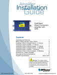
The SenGenuity wireless SAW resonator (SAWR) based temperature sensing solution consists of a reader
(RF Transceiver) RF or capacitively linked to one or more SAWR sensing elements as depicted in Figure 1.
The system operates in a range from 428 MHz to 439 MHz.
4
Figure 1: Wireless SAW Temperature Sensing System
Wireless sensors based on changes in resonant frequency require an appropriate reader. TempTrackr reader is
base on “time domain” approach which is typically employs double heterodyne down-conversion with inphase and quadrature sample streams at base-band. Direct down-conversion and single heterodyne
conversion are possible although the susceptibility to possible out-of-band spurious signals is worse.
Discrete Fourier Transform (DFT) analysis of the in-phase and quadrature samples to obtain power spectral
density (PSD) and curve fit interpolation of the PSD values is employed. While these extra steps incur
additional electronics complexity and computational burden, they overcome the limitations of the purely
“frequency domain” method. The spacing of the interrogation frequencies is primarily limited by the
bandwidth of the resonator response of the sensor and the bandwidth of the pulse’s power spectral density.
Saturation of the receiver is desired in the time domain samples since frequency information is not lost
through saturation. The effects of saturation in frequency domain and time domain readers is analogous to
the same effect in amplitude modulated (AM) versus frequency modulated (FM) radio receivers.
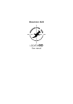
In the time domain, saturation tends to make the ring-down of the resonator appear longer and more
uniform, resulting in better apparent accuracy, as seen in Figure 3. The degree of saturation should still be
somewhat limited to prevent deterioration of the spurious signal rejection ratio.
W ave Amplitude
1
0.5
0
-0.5
-1
0
2
4
6
8
10
12
14
16
18
20
Time (microseconds)
Figure 3. The decay envelope is shown for a resonator with a Q of 10,000. The blue lines indicate the received signal with no
saturation. Red, purple and black indicate 2x, 5x, and 10x amplitude saturation resulting in 2.5, 6, and 8.5 μs of apparent increase in
the decay time of the digitized waveform.
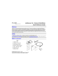
The Q of the SAW resonator is a critical parameter, both as the unloaded Q and as the loaded Q
determined by the radiation resistance and loss resistances of the antenna. Figure 4 illustrates that the
resonator, with an unloaded Q of nearly 12,000, requires a loaded Q of at least 6,000 for high received
signal strengths. A low-Q resonator of similar design is also shown with an unloaded Q of approximately
7,500. The diminished pulse width is seen to reduce the received power by 3 dB. These values of Q are
5
readily achievable with SAW resonators.
Effective Relative Power of Received Response
2
0
-2
-4
-6
-8
-10
-12
2000
4000
6000
8000
Loaded Resonator Q
10000
12000
Figure 4. A SAW response with high Q (TFSS432, solid) is analyzed assuming a 1μs switching time between interrogation pulse and
receiving and a 22 μs receive gate time. The roll-off at very high loaded Q’s result because the wave is not sufficiently reradiated by
the antenna. The roll-off at low
Figure 5. Interrogation unit (reader) and three typical SAW temperature sensor modules. The sensor elements are 3.8mm x 3.8mm
ceramic-packaged resonators embedded in the PCB package. The coil antenna shown has been designed for operation in the vicinity
of 433 MHz with a desirable radiation pattern.
6
Figure6. In standalone applications, the temperatures can be displayed as shown on this PC screen image. Typical installations embed
the reader electronics into the overall system monitoring electronics.
7
_______________________________3. Software Installation & Operation____
(Note: This section may nit apply if users do not purchase the software and/or have no access to the
installed software)
This section describes the following:
8
•
Reader and USB-CAN-BUS
•
Temperature Sensor Software
9
•
Run the Interrogation
•
TempTrackr Application Settings & Calibration:
10
•
Advanced View
•
Log Data
11
•
TempTrackr Program Features
12
•
TempTrackr Program Features
•
Receive Power (RX)
13
•
TempTrackr Screen Display
14
___________
_4. Operations: Safety Precautions____
In compliance to Agency certification and requirements for operating safety warning
instructions, Vectron International is providing the following information for the safe operation
of the Wireless Temp Tracker system and Wireless Reader. This information applies to all
models/configurations of the system (Models TempTrackr-03, -06, -09) and stand-alone
Wireless readers (Model WSR-T2), used either as Vectron-furnished turn-key system or when
integrated into users’ equipment.
The Temp tracker as a system or key individual components have been certified for EMC
compatibility using various national/country certification directives and standards, and will be
affixed with an appropriate certification ID (e.g. FCC, IC ID, CE marking etc.)1. These
certifications apply only with a certain operating configuration of the device (e.g. transmit power
level, duty cycle etc.) in order to comply with the associated functional requirements for
compliance. For a compliant product, which is so labeled, the configuration will be fixed as
required (e.g. through user software) at the time of shipment when customers are ordering a
compliant product so-labeled.
USERS ARE CAUTIONED THAT ANY ATTEMPT TO ALTER THE PRODUCT
CONFIGURATION EITHER THROUGH HARDWARE OR SOFTWARE
MODIFICATION WILL RENDER THE PRODUCT NON-COMPLIANT AND WILL VOID
VECTRON’S WARRANTY PROVISIONS IN THE TERMS & CONDITIONS OF SALE.
CAUTION
(Statements legally required under country laws or certification agencies)
U.S. Federal Communication Commission Interference Statement
1
The TempTrackr system has been tested to meet various U.S. and International EMC RF radiation/emissions
compliance requirements (U.S. FCC, Canadian, European standards). Registered ID’s may vary by product model
but generally appear on the product labels as:
FCC ID X3ITEMPTRACKR
IC: 8085B-TEMPTRACKR
15
This equipment has been tested and found to comply with the limits for a Class B digital device,
pursuant to Part 15 of the FCC Rules. These limits are designed to provide reasonable
protection against harmful interference in a residential installation. This equipment generates
uses and can radiate radio frequency energy and, if not installed and used in accordance with
the instructions, may cause harmful interference to radio communications. However, there is no
guarantee that interference will not occur in a particular installation. If this equipment does
cause harmful interference to radio or television reception, which can be determined by turning
the equipment off and on, the user is encouraged to try to correct the interference by one of the
following measures:
- Reorient or relocate the receiving antenna.
- Increase the separation between the equipment and receiver.
- Connect the equipment into an outlet on a circuit different from that to which the receiver is
connected.
- Consult the dealer or an experienced radio/TV technician for help.
This device complies with Part 15 of the FCC Rules. Operation is subject to the following two
conditions: (1) This device may not cause harmful interference, and (2) this device must accept
any interference received, including interference that may cause undesired operation.
FCC Caution: Any changes or modifications not expressly approved by the party responsible for
compliance could void the user's authority to operate this equipment.
Industry Canada Compliance
Operation is subject to the following two conditions: (1) this device may not cause interference,
and (2) this device must accept any interference, including interference that may cause
undesired operation of the device.
This device has been designed to operate with antennas having a maximum gain of XdBi.
Antennas having a gain greater than XdBi are strictly prohibited for use with this device. The
required antenna impedance is 50 ohms.
To reduce potential radio interference to other users, the antenna type and its gain should be so
chosen that the equivalent isotropically radiated power (e.i.r.p.) is not more than that permitted
for successful communication.
RF Exposure Statements
For MOBILE devices subject to RF Exposure concerns: (e.g., 15.247 devices)
WARNING!
FCC and IC Radiation Exposure Statement:
This equipment complies with FCC’s and IC’s RF radiation exposure limits set
forth for an uncontrolled environment under the following conditions:
16
1. This equipment should be installed and operated such that a minimum
separation distance of 20cm is maintained between the radiator (antenna) &
user’s/nearby person’s body at all times.
2. This transmitter must not be co-located or operating in conjunction with any
other antenna or transmitter.”
For PORTABLE devices where Specific Absorption Rate (SAR) testing is applicable:
WARNING!
FCC and IC Radiation Exposure Statement:
This portable equipment with its antenna complies with FCC’s and IC’s RF
radiation exposure limits set forth for an uncontrolled environment. This
equipment has shown compliance with FCC’s and IC’s Specific Absorption Rate
(SAR) limits. To maintain compliance follow the instructions below:
1. This transmitter must not be co-located or operating in conjunction with any
other antenna or transmitter.
The following may or may not apply to portable devices with SAR results.
Applicable statements will probably be different from device to device and may
need to be examined on a case by case basis.
2. {If equipment is supplied with accessories, (e.g., belt clip for body worn
operation) then a warning should be included to restrict the use of the device only
to the accessories tested during SAR evaluation. Accessories with metal
components should not be used with the device, unless specifically tested.}”
For PORTABLE devices where SAR in NOT applicable: (power[mW] < 60/f[Ghz])
WARNING!
FCC and IC Radiation Exposure Statement:
This portable equipment with its antenna complies with FCC’s and IC’s RF
radiation exposure limits set forth for an uncontrolled environment. To maintain
compliance follow the instructions below:
1. This transmitter must not be co-located or operating in conjunction with any
other antenna or transmitter.
2. Avoid direct contact to the antenna, or keep contact to a minimum while using
this equipment.”
For MODULAR devices subject to RF Exposure concerns:
“This transmitter module is authorized to be used in other devices only by
OEM integrators under the following conditions:
1. The antenna(s) must be installed such that a minimum separation
distance of 20cm is maintained between the radiator (antenna) &
user’s/nearby person’s body at all times.
17
2. The transmitter module must not be co-located with any other antenna or
transmitter.
As long as the two conditions above are met, further transmitter testing will not
be required. However, the OEM integrator is still responsible for testing the endproduct for any additional compliance requirements with this module installed.
(i.e., digital device emissions, PC peripheral requirements, etc.)
IMPORTANT NOTE: In the event that these conditions cannot be met (for certain
configurations or co-location with another transmitter), then the FCC / IC
authorization is no longer considered valid and the FCC ID / IC number cannot
be used on the final product. In these circumstances, the OEM integrator will be
responsible for re-evaluating the end product (including the transmitter) and
obtaining a separate FCC / IC authorization.
The OEM integrator must be made aware not to provide information to the end
user regarding how to install or remove this RF module in the user manual of the
end product.
The user manual for the end product must include the following information in a
prominent location:
“To comply with FCC’s and IC’s RF radiation exposure requirements, the
antenna(s) used for this transmitter must be installed such that a minimum
separation distance of 20cm is maintained between the radiator (antenna) &
user’s/nearby person’s body at all times and must not be co-located or operating
in conjunction with any other antenna or transmitter.””
CE Marking & Compliance:
To be compliant to the EU directive 2004/108/EC for EMC for Short Range Radio Frequency
devices, the Temp Tracker system or the Wireless reader is configured as required (e.g.
through user software) to operate only within the unlicensed 433MHz ISM band (frequency
range 433,05MHz to 434,79 MHz) (433MHz ISM band). Therefore when the shipped product is
labeled with CE marking, users must operate the product only within this permissible frequency
band at the permissible power level allowed by the regulations.
Customers are advised that any modification or operation of the reader that is CE- marked
outside of the permitted frequency band and power level limits will render the product noncompliant to those standards. Customers are solely responsible for certification of their endproduct to the applicable country standards should the CE-marked reader sold by Vectron be
integrated into the end-product sold by customers and the reader is modified or operated
outside of the original CE certification limits. Vectron assumes no liability for operation of any
CE-marked reader in any manner inconsistent with the requirement of the applicable standards.
Any use outside the ISM band/frequency should be reviewed by customers and certified in the
EU country by country.
18


![80-00 [更新済み]](http://vs1.manualzilla.com/store/data/006650731_2-ee5a274f1c8f345559eec423601c9443-150x150.png)