1
User Manual
Notices & W
arranties
Warranties
Copyright Regulations
It is illegal for anyone to violate any of the rights provided by the copyright laws to the owner of
copyright, except for fair use (mainly private noncommercial use). Also, in certain cases copying is
prohibited with no exceptions. In no event shall Canopus be liable for any direct or indirect damages whatsoever arising from the use of captured materials.
Warranty
Your ADVC-1000 options are covered by a limited warranty when you register your Canopus product. This warranty is for a period of three years from the date of purchase from Canopus or an
authorized Canopus agent. This warranty applies only to the original purchaser of the Canopus
product and is not transferable, Canopus Co., Ltd. warrants that for this period the product will be
in good working order. Should our product fail to be in good working order, Canopus will, at its
option, repair or replace it at no additional charge, provided that the product has not been subjected to misuse, abuse or non-Canopus authorized alternations, modifications and/or repair. Proof
of purchase is required to validate your warranty.
Canopus is not responsible for any lost profits, lost savings or other incidental or consequential
damages arising out of the use of, or inability to use, this product. This includes damage to property
and, to the extent permitted by law, damages for personal injury. This warranty is in lieu of all other
warranties of merchantability and fitness for a particular purpose.
Cautions
Notices & W
arranties
Warranties
Please observe the following cautions when using this product. If you have any questions regarding
the method of usage, the descriptions herein, or any other concerns, please contact Canopus Technical Support.
DANGER
The following conditions indicate the potential for serious bodily injury or loss of life.
Health precautions
In rare cases, flashing lights or stimulation from the bright light of a computer display or TV monitor
may trigger temporary epileptic seizures or loss of consciousness. It is believed that even individuals whom have never experienced such symptoms may be susceptible. If you or close relatives
have experienced any of these symptoms, consult a doctor before using this product.
Do not use in environments requiring a high degree of reliability and safety
This product is not to be used in medical devices or life support systems. The characteristics of this
product is not suited for use with such systems.
ii
Notices & W
arranties
Warranties
Protect against static electricity
An electrostatic discharge may damage components of this product. Do not directly touch any of
the connectors or component surfaces.
Static electricity can be generated on clothing and on people. Before handling the product, discharge static electricity from your body by touching a grounded metal surface.
Do not disassemble
Do not remove the cover or modify the Product. Fire, electric shock or malfunction may result. For
internal inspection or repair, please contact your system integrator or Canopus directly.
Do not operate at other than the specified voltage
Do not operate at other than the specified voltages of AC 100-240V. Operation at other than the
rated voltage may result in fire or malfunction.
Do not operate with other than the specified power supply
Do not operate with other than the specified AC adapter, or with a car power supply. Such operation may result in fire or malfunction.
Handle the AC adapter cord carefully
CAUTION
The following conditions indicate the potential for bodily harm, damage to hardware or loss of data.
Do not pull AC adapter cord when disconnecting from electrical outlet
When disconnecting the AC adapter cord, pull on the plug, not the cord itself. Pulling on the cord
can damage the cord and may result in fire or electric shock.
Do not touch AC adapter with wet hands
Do not disconnect or plug in the AC adapter when your hands are wet. Contact with water may
result in electric shock, fire or damage.
Notices & W
arranties
Warranties
Do not place heavy objects on top of the cord, or place it near hot objects. Doing so may damage
the cord and result in fire, electrical shock, or malfunction. Altering the cord, or excessively bending
or pulling the cord may result in fire or electrical shock. If the cord is damaged, please contact your
local retail outlet or Canopus directly.
Do not setup in areas subject to heat
Do not setup in an area exposed to direct sunlight or near a heating apparatus. The heat can accumulate, causing burns, fire or damage. Also, the unit may become deformed or change color.
iii
Notices & W
arranties
Warranties
Only setup using the prescribed method
Do not setup in a manner other than prescribed. Do not use while wrapped in cloth or plastic. Heat
can accumulate, causing burns, fire or damage.
If product will not be used for an extended period
If this product will not be used for an extended period of time, disconnect the AC adapter from the
electrical outlet.
Do not cover the ADVC-1000 ventilation
Do not use the ADVC-1000 covered with a cloth or in an ill-ventilated room.
Covering the vent may cause heat inside of the product resulting in fire or product malfunction.
FCC Notice
This equipment has been tested and found to comply with the limits for a Class A digital device,
pursuant to Part 15 of the FCC Rules. These limits are designed to provide reasonable protection
against harmful interference when the equipment is operated in a commercial environment. This
equipment generates, uses, and can radiate radio frequency energy and, if not installed and used in
accordance with the instruction manual, may cause harmful interference to radio communications.
Operation of this equipment in a residential area is likely to cause harmful interference in which
case the user will be required to correct the interference at his own expense.
CE Notice
Notices & W
arranties
Warranties
WARNING
This is a class A product. In a domestic environment this product may cause radio interference in
which case the user may be required to take adequate measures.
Declaration of Conformity
According to FCC Part 15
Responsible Party Name:
Canopus Co.,Ltd.
Address:
1-2-2 Murotani Nishi-ku, Kobe-city Hyogo 651-2241 Japan
Telephone:
+81-78-992-5846
Declares that product Model:
ADVC-1000
Complies with Part 15 of the FCC Rules.
iv
Notices & W
arranties
Warranties
Product Notes
1. Unauthorized copying of a portion or the entirety of this product is prohibited.
2. The description and specifications of this product are subject to future change without
notice.
3. The description of this product has been prepared to be as complete as possible.
If the reader is aware of any questionable points, errors or omissions, please contact
Canopus.
4. The company assumes no liability for the results of practical application, regardless of
item (3) above.
5. Regardless of whether negligence occurs during usage, the company assumes no
liability, even if there is a claim for extraordinary, incidental or derivative loss, including
the loss of profits, that arises during practical application of this product.
6. The analysis, reverse engineering, recompiling and disassembling of the software,
hardware or manuals that accompany this product, and all other related products including miscellaneous supplemental items, are prohibited.
7. Canopus, as written in both English and Japanese, and its logo are registered trademarks
of Canopus Co., Ltd.
8. ADVC is registered trademark of Canopus Co., Ltd.
Notices & W
arranties
Warranties
9. Other product names and related items are trademarks or registered trademarks of their
respective companies.
v
Notices & W
arranties
Warranties
About the Documentation
This document is the ADVC-1000 User Manual.
Information not listed in this document may be listed elsewhere.
In cases where there is a difference between a description in this documents and an actual operation method, the actual operation method takes precedence.
About This Manual
The information contained in this manual covers the installation and specific functionality of this
product.
Chapter 1 — Introduction
Provides information about contacting us and using this manual.
Chapter 2 — Basic Instructions
Describes the part names and functions and other basics of this product.
Notices & W
arraties
Warraties
vi
Chapter 1
Table of Contents
Hardware Installation
Table of Contents
Table of Contents
Copyright Regulations ............................................................................ ii
Warranty ................................................................................................... ii
Cautions ................................................................................................... ii
DANGER ................................................................................................... ii
CAUTION .................................................................................................. iii
FCC Notice ............................................................................................... iv
CE Notice ................................................................................................. iv
Declaration of Conformity ...................................................................... iv
Product Notes .......................................................................................... v
About the Documentation ...................................................................... vi
About This Manual .................................................................................. vi
Table of Contents .................................................................................... viii
Chapter 1 Introduction ............................ 1
1-1 Package Contents ............................................................................. 2
1-2 Features of the ADVC-1000 .............................................................. 2
Chapter 2 Basic Instructions ................... 3
2-1 Part Names and Functions ............................................................... 4
Table of Contents
ADVC-1000 Front panel ......................................................................................... 4
ADVC-1000 Rear panel .......................................................................................... 6
LCD Screen Displays .............................................................................................. 7
DIP Switch settings ................................................................................................ 15
2-2 Connecting Devices .......................................................................... 16
Connecting the ADVC-1000 unit (Standard) ........................................................ 16
Connecting the ADVC-1000 (System integrated) ................................................ 17
Quick Setting .......................................................................................................... 17
Importing SDI data to your PC .............................................................................. 18
Recording PC-edited data onto a tape with VTR ................................................ 18
2-3 Setting Menu ..................................................................................... 19
Data Conversion Process Menu ............................................................................ 19
2-4 Specifications .................................................................................... 31
viii
Supplementary:
Outputting Component signals (optional) ............................................ 32
Chapter 1
HardwareIntroduction
Installation
Thank you for purchasing the
Canopus ADVC-1000 Advanced
DV/SDI Converter. Before you start
using your system, please read this
manual and follow the installation
instructions. This will ensure that
you have a trouble-free setup. If you
have any questions please call, fax,
mail or email us at your local
Canopus office or distributor.
Introduction
1-1 P
ack
age Contents
Pack
ackage
The below items are included in your ADVC-1000 package:
• 1 x ADVC-1000 unit
• 1 x AC Adapter
• 1 x AC Cable
• 1 x DV Cable (6-pin to 4-pin)
• 1 x Manual
ADVC-1000 User Manual (This document)
1-2 F
eatures of the ADVC-1000
Features
1. Digital-to-Digital Conversion Unit
The ADVC-1000 converts SDI signals and DV signals bidirectional. SDI (serial digital interface) signals are the standard signal for professional digital video, and DV (digital video) signals
have a high PC compatibility. The ADVC-1000 uses a proven
Canopus DV codec, ensuring that converted signals have a
solid quality.
2. DV-SDI Conversion Generates Perfectly Synchronized
Signals (Advanced Mode)
Introduction
2
The ADVC-1000 converts DV signals to SDI signals while receiving a sync signal from an external source. An original Canopus synchronization technology (patent pending) enables DVSDI conversion with output signals completely synchronized
to the reference signal, preventing frame skips or frame holds
during the process.
3. Professional Specifications Adapted to a Variety of
Studio Uses
Designed for a quick and easy introduction to a wide range of
studio systems, the ADVC-1000 features AV/C-R422 conversiondriven VTR control and a full complement of reference input
and LTC I/O. Four-channel embedded audio support enables
creation of a wide range of video systems.
Chapter 2
1
Basic Instructions
Hardware
Installation
This chapter explains the part
names and functions and other
basics of the ADVC-1000.
- Part names and functions
- Connecting devices
- Setting Menu
- Specifications
Basic Instructions
2-1 P
art Names and F
unctions
Part
Functions
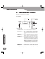
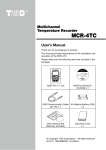
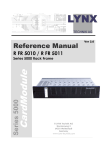
ADVC-1000 Front Panel
The front panel of the ADVC-1000 contains the following controllers
and indicators:
1. POWER switch -- Turns the ADVC-1000 power ON/OFF.
2. Select key --------- Move up/down to select menu items, and left/
right to change settings. Used to apply
selected settings of items without submenus.
Basic Instructions
3. MENU key --------- Press to switch the LCD screen's display
between the main screen and menu screen.
4. ENTER key -------- Press to return to the main screen after
making settings in the menu screen. For items
with sub-menus, press this key to display the
sub-menu screen. For items with sub-menus,
select the desired setting, then press the
ENTER key again to apply it. If you don't want
to change the setting of a sub-menu screen,
press the MENU key to return to the main
screen.
5. Mode switch ----- Toggles between the SDI J DV and DV J
SDI conversion modes.
* The operation modes cannot always be switched depending on the settings
in the menu screen. (See p. 28.)
4
Basic Instructions
Front Panel LEDs
x Mode indicator (LED)
When only the “SDI J DV” LED is lit, ADVC-1000 converts the
SDI video signal, SDI embedded audio signal or AES/EBU
audio signal to a DV signal. When only the “DV J SDI” LED is
lit, ADVC-1000 converts the DV signal to an SDI video signal,
SDI embedded audio signal and AES/EBU audio signal.
x STATUS LED
Off: ........................ 9-pin remote control is disabled.
Lit green: .............. 9-pin remote control is enabled.
Lit red: .................. 9-pin remote control was set to enabled, but
remote control is prevented by a communication error. Check that the 9-pin remote
cable is correctly connected, that the connected device's power is ON, and that the
remote control setting has been enabled on
the connected device.
Basic Instructions
Flashing red: ........ A major ADVC-1000 operation error has occurred, or several signals required for operation can't be detected. Check the error status display screen. Input the required signals
correctly, or change ADVC-1000's settings.
5
Basic Instructions
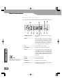
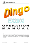
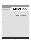
ADVC-1000 Rear Panel
The rear panel of the ADVC-1000 contains the following connectors
1. MONITOR OUT --------- Output connectors for video monitor,
speakers.
2. REF ------------------------- Input connectors receiving sync signal.
The LED lights red when sync signal
input is detected. The REF connector
has through output. If a cable is not
connected to the output connector, it
has a 75 automatic termination.
3. TC --------------------------- Time code I/O connectors.
4. AES/EBU ------------------ Digital audio signal I/O connectors.
Basic Instructions
5. SDI -------------------------- I/O connectors for digital video and
embedded audio signals. When SDI input
is detected, the LED next to the SDI input
connector lights red. During SDI output,
the LED next to the SDI output connector
lights red.
Info
When connecting a PC to the
ADVC-1000 unit, make sure that
the PC’s power is turned off.
6. DV1 ------------------------- 6-pin DV connector.
7. DV2 ------------------------- 4-pin DV connector.
8. REMOTE ------------------ Remote control connector.
9. DC-IN 12V ---------------- 12V DC power supply terminal. Use the
AC adapter provided.
6
Basic Instructions
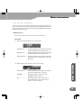
LCD Screen Displays
There are three main screens, switched by moving the Select key
up/down. Move the Select key left/right to switch between the error
status screen and the main screens. Pressing the MENU key displays
the Settings Menu screen.
Main Screen 1
This screen shows the current status of the operation.
x SDI J DV
1. DV audio output (Upper left on the screen)
48kHzCH1/2 .......... Encoding digital audio input CH1 and CH2
to 48 kHz/16 bit/2 channel DV audio.
48kHzCH3/4 .......... Encoding digital audio input CH3 and CH4
to 48 kHz/16 bit/2 channel DV audio.
32kHzCH1234 ....... Encoding digital audio input CH1, CH2,
CH3 and CH4 to 32 kHz/12 bit/4 channel
DV audio.
Embedded ............ Obtaining digital audio input from embedded audio of SDI input connector.
AES/EBU .............. Obtaining digital audio input from
AES/EBU input connector.
SG ......................... Obtaining digital audio input from 1
kHz/-20 dB audio signal (only during
built-in color bar output).
Basic Instructions
2. Digital audio input (Upper right on the screen)
7
Basic Instructions
3. 9-pin remote control deck status (Lower left on the screen)
If blank .................. 9-pin remote control is not in use.
NoDevice .............. Can't find deck. Check cable connection.
NoCASETTE ......... No tape in deck.
STOP .................... Deck is stopped.
PLAY ..................... Deck is playing.
STILL ..................... Deck is paused.
F.FWD ................... Deck is fast-forwarding.
REW ...................... Deck is rewinding.
REC ....................... Deck is recording.
SHUTTLE .............. Deck is shuttling.
4. Input time code display (Lower right on the screen)
00:00:03:22 .......... For PAL/NTSC NDF (Non Drop Frame)
Basic Instructions
8
Info
Free-run time code is used
during built-in color bar output
or when time code is not input.
* A colon is used between seconds and frames
as a delimiter.
00:00:03;22 .......... For NTSC DF (Drop Frame)
* A semicolon is used between seconds and
frames as a delimiter.
--:--:--:-- ................ No DV signal output
Basic Instructions
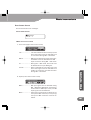
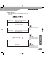
x DV J SDI
1. DV audio input (Upper left on the screen)
32kHz/4ch > both
REC
00:00:03;22
48kHz/2ch ............. DV audio input is 48 kHz/ 16 bits/
2 channels. Digital audio output CH3
and CH4 are copies of CH1 and CH2.
32kHz/4ch ............. DV audio input is 32 kHz/ 12 bits/
4 channels.
32kHz/2ch ............. DV audio input is 32 kHz/ 16 bits/
2 channels. Digital audio output CH3
and CH4 are copies of CH1 and CH2.
44kHz/2ch ............. DV audio input is 44.1 kHz/ 16 bits/
2 channels. Digital audio output CH3
and CH4 are copies of CH1 and CH2.
No Stream ............ No DV signal input.
SG ......................... Digital audio output is 1 kHz/-20 dB
audio signal regardless of DV signal
input (only during built-in color bar
output).
32kHz/4ch > both
REC
00:00:03;22
both ...................... Same signal is output for SDI embedded audio output and AES/EBU audio
output.
3. 9-pin remote control deck status (Lower left on the screen)
32kHz/4ch > both
REC
00:00:03;22
Basic Instructions
2. Digital audio output destination (Upper right on the screen)
Same as during SDI J DV mode.
(See p. 8. “9-pin remote control deck status”)
9
Basic Instructions
4. DV input time code (Lower right on the screen)
32kHz/4ch > both
REC
00:00:03;22
00:00:03:22 .......... For PAL/NTSC NDF (Non Drop Frame)
* A colon is used between seconds and frames
as a delimiter.
Info
Free-run time code is used
during built-in color bar output
or when a valid time code is not
in the DV signal.
00:00:03;22 .......... For NTSC DF (Drop Frame)
*A semicolon is used between seconds and
frames as a delimiter.
--:--:--:-- ................ No DV signal input
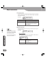
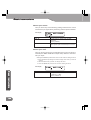
Main Screen 2
This screen shows information on the current settings.
1. Analog monitor audio output (Upper side on the screen)
Monitor out:1+3/2+4
TC source:DVITC NTSC
1/2 ......................... Outputs CH1/CH2.
3/4 ......................... Outputs CH3/CH4.
1+3/2+4 ............... Outputs MIX of CH1 and CH3, MIX of CH2
and CH4.
Basic Instructions
10
1+2+3+4 ............. Outputs MIX of CH1, CH2, CH3 and CH4.
2. Time code input (Lower middle on the screen)
Monitor out:1+3/2+4
TC source:DVITC NTSC
DVITC .................... DVITC signal in SDI video input signal is
acquired, and converted into time code
in output DV signal.
When deck control by remote connector is enabled
Acquires VITC through the remote connector to use for time code. If VITC cannot be acquired, DVITC in SDI video input signal is used.
Basic Instructions
LTC ........................ LTC signal input to TC connector is acquired, and converted into time code in
output DV signal.
When deck control by remote connector is enabled
If the LTC signal input to TC connector is
invalid, LTC acquired through the remote
connector is used.
auto ....................... DVITC signal in SDI video input and LTC
signal input to TC connector are acquired
through the remote connector. If the LTC
signal is valid, the LTC is converted into
time code in output DV signal. Otherwise,
DVITC is converted into time code.
When deck control by remote connector is enabled
If the LTC signal input to TC connector is
invalid, LTC/VITC auto selection time code
is acquired through the remote connector. If the auto selection TC cannot be acquired, DVITC in SDI video input signal is
used.
3. Video standard (Lower right on the screen)
NTSC .................... ADVC-1000 operates in NTSC mode.
PAL ........................ ADVC-1000 operates in PAL mode.
Info
The video standard is set by DIP
switch SW4 on the bottom of the
unit, or by the menu option "19
video standard".
(See "DIP switch settings" on p.15
and "19 video standard" on p.23)
Basic Instructions
Monitor out:1+3/2+4
TC source:DVITC NTSC
11
Basic Instructions
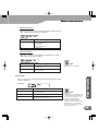
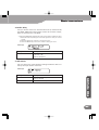
Main Screen 3
This screen shows information on the current settings.
1. External synchronization enabled/disabled (Upper side on
the screen)
GENLOCK:enable
REMOTE:enable
disable .................. External synchronization function is
disabled.
enable ................... External synchronization function is
enabled.
advanced .............. External synchronization function in the
"advanced mode" is enabled. (See p.25)
2. 9-pin remote enabled/disabled
GENLOCK:enable
REMOTE:enable
disable .................. 9-pin remote control function is disabled.
enable ................... 9-pin remote control function is enabled.
Basic Instructions
12
Basic Instructions
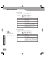
Error Status Screen
This screen shows error messages.
x Error Status Screen
x When error has occurred
1. Time code (Upper side on the screen)
LTC ........................ LTC was selected for time code input, and
time code signal can't be detected from
TC connector during SDI J DV mode.
DVITC ................... DVITC was selected for time code input,
and DVITC can't be detected from SDI
input connector during SDI J DV mode.
autoTC .................. Auto is selected for time code input, and
time code signal can't be detected from
neither TC connector nor SDI connector
during SDI J DV mode.
2. Inputs (Lower side on the screen)
SDIin ..................... SDI input signal can't be detected during
SDI J DV mode. Alternately, external synchronization to SDI input is set, but SDI
input signal can't be detected.
Basic Instructions
TC .......................... During DV J SDI mode, time code can't
be detected from input DV signal.
REFin .................... Unit is set to synchronize to reference signal input to REF connector, but sync signal input to REF connector can't be detected.
13
Basic Instructions
AES12 ................... AES/EBU audio input is selected for SDI
J DV mode, but signal for CH1 and CH2
used for DV encoding can't be detected.
AES 34 .................. AES/EBU audio input is selected for SDI
J DV mode, but signal for CH3 and CH4
used for DV encoding can't be detected.
AES1234 ............... AES/EBU audio input is selected for SDI
J DV mode, but signal for CH1, CH2, CH3
and CH4 used for DV encoding can't be
detected.
Other Errors
Variation in input signal exceeded ADVC-1000's jitter attenuation
function tolerance limit. Change the setting of menu item 62 ("jitter attenuator") to "off".
Basic Instructions
14
When the DV audio encoding setting is 32 kHz, the "selected audio" setting of menu item 13 ("digital audio out") has no effect.
Change the setting of the "digital audio out" item to "through out",
or change the DV audio encoding setting to 48 kHz.
Basic Instructions
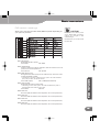
DIP switch settings
Allow you to set various modes. SW3, SW4 may differ depending on
your point of purchase.
CAUTION
Make sure to turn off the power
of the ADVC-1000 unit before
making any changes for DIP
switch settings.
DIP switches 5, 6, 7 and 8 should
be set to OFF.
SW1: PHY Speed
Designates the PHY speed.
OFF: S400
ON: S200
SW2: Update Mode
Used to update the internal software. (Set this switch to the off
position for normal operations.)
OFF: Normal
ON: Update
* This switch is ignored, unless the menu option "19 video standard
(see p.23)" is set to "set by DIP switch".
OFF: 0 IRE (Japan)
ON: 7.5 IRE (North America)
SW4: Video Format
Designates the video signal format.
* The settings in the menu option "19 video standard (see p.23)" is
adopted when this switch is set to OFF.
OFF: NTSC
ON: PAL
SW5: Reserved
Not used. (Set this switch to the off position for normal operations.)
SW6: Reserved
Not used. (Set this switch to the off position for normal operations.)
Basic Instructions
SW3: NTSC Setup Level
Designates the black (setup) level. Enabled only when the video
format (standard) is NTSC.
SW7: Reserved
Not used. (Set this switch to the off position for normal operations.)
SW8: Reserved
Not used. (Set this switch to the off position for normal operations.)
15
Basic Instructions
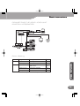
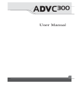
2-2 Connecting Devices
CONNECTING THE ADVC-1000 UNIT
(STANDARD)
Connect the ADVC-1000 unit to your system. The diagram below
illustrates the typical connection of the ADVC-1000.
CAUTION
DV editing software is required
to playback or capture AVI video
files for use on a PC or to record
the file data onto tape. In
addition, the PC should be
equipped with an IEEE-1394 port.
Basic Instructions
16
Info
When connecting a PC to the
ADVC-1000 unit, make sure that
the PC’s power is turned off.
Basic Instructions
CONNECTING THE ADVC-1000 UNIT
(SYSTEM INTEGRATED)
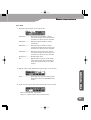
Quick Setting
Mode
Setting item
Settings
DV J SDI
22 DVITC insert line
Selecting line No. or off
24
31 ext. sync
disable, enable, advanced
25
11 DV audio encode
48kHz CH1/2, 32kHz CH1234,
48kHz CH3/4
20
12 digital audio in
Embedded, AES/EBU
20
21 TC input source
DVITC, LTC, auto
24
* There are other several settings. Refer to “2-3 Setting Menu” (See P.19)
Basic Instructions
SDI J DV
Ref. page
17
Basic Instructions
Importing SDI data to your PC
Import the material of the tape on VTR into a PC.
1. Press the [Mode] switch on the front panel of the ADVC-1000
to switch the mode to the “SDI J DV” mode.
2. Press the [MENU] switch on the front panel of the ADVC-1000,
and operate the select switch to select the desired setting.
3. Capture the data by using DV editing software.
* For the operational procedure of the DV editing software, refer to the
instruction manual provided with your DV editing software.
Recording PC-edited data onto a tape
with VTR
Export the DV data on the PC into the VTR.
1. Press the [Mode] switch on the front panel of the ADVC-1000
to switch the mode to the “DV J SDI” mode.
2. Use the DV editing software to output your data.
* For the operational procedure of the DV editing software,
refer to the instruction manual provided with your DV
editing software.
3. Use the VTR to record the data on tape.
Basic Instructions
18
Basic Instructions
2-3 Setting Menu
Data Conversion Process Menu
1. Press the MENU key.
2. Menu items are displayed on the LCD screen.
3. Move the Select key up/down to select the desired menu item,
then left/right to change the setting of the selected item. With the
desired setting selected, press the ENTER key to apply the setting
and return to the main screen.
4. If the current item has a sub-menu, press the ENTER key to dis-
Select Key Operation
x
Used to select setting item (toggle sequentially among
menu items 11 to 72 shown below).
x
Used to select setting for selected menu item (the Select key operations, right or left, select the corresponding setting).
Settings Menu Item Nos.
10 to 19: ...... A/V input/output settings ........................... 20-23
20 to 29: ...... Time code settings ........................................ 24-25
30 to 39: ...... External synchronization settings .............. 25-27
40 to 49: ...... 9-pin remote control settings ...................... 27-28
50 to 59: ...... Signal generator output settings ................ 28
60 to 69: ...... Other detailed settings ................................. 29-30
Info
When you change the settings of
DIP switches SW3 and SW4, or
the settings in the menu option
"19 video standard", the unit
restores the other settings than
the video standard to the one at
the time of factory shipment.
(See "DIP switch settings" on p.15
and "19 video standard" on p.23)
Basic Instructions
play the sub-menu, letting you select a setting. After selecting the
setting, press the ENTER key again to apply it. If you don’t want to
change the setting, press the MENU key to return to the main
screen.
70 to 79: ...... System settings ............................................. 30
19
Basic Instructions
11 DV audio encode
Lets you select any of the following settings below related to the
DV audio format used for DV encoding.
LCD Display
Setting
Description
48kHz CH1/2
48 kHz/2 channels; encode CH1 and CH2
audio inputs.
(Factory default)
32kHz CH1234
32 kHz/4 channels; encode CH1, CH2, CH3
and CH4 audio inputs.
48kHz CH3/4
48 kHz/2 channels; encode CH3 and CH4
audio inputs as CH1 and CH2 for DV.
12 digital audio in
Lets you select any of the following settings related to the
digital audio input in SDI J DV mode (during DV encoding).
LCD Display
Info
Basic Instructions
20
When the DV audio encoding
setting is 32 kHz, the "selected
audio" setting has no effect.
Change the setting to "through
out", or change the DV audio
encoding setting of menu item 11
("DV audio encode") to 48 kHz.
DV audio input is output in DV J
SDI mode (during DV decoding).
Setting
Description
Embedded
Selects SDI embedded audio.
(Factory default)
AES/EBU
Selects AES/EBU audio.
13 digital audio out
Lets you select any of the following settings related to the
digital audio output.
LCD Display
Setting
Description
through out
Outputs each input source audio directly.
(Factory default)
selected audio
Outputs audio selected for “12 digital audio
in” menu item.
Basic Instructions
14 analog audio mon.
Lets you select any of the following settings related to the
output to the analog monitor audio output connectors.
LCD Display
Setting
Description
CH1/2
Outputs audio CH1 and CH2.
(Factory default)
CH3/4
Outputs audio CH3 and CH4.
CH1+3/2+4
Outputs mix of audio CH1 and CH3, and mix
of audio CH2 and CH4.
CH1+2+3+4
Outputs mix of audio CH1, CH2, CH3 and
CH4.
15 SDIout auto-off
Lets you select a control process that automatically stops the SDI
output in SDI J DV mode (during DV encoding).
LCD Display
Description
off
Doesn’t stop SDI output.
(Factory default)
on
Stops SDI output.
Info
When the ADVC -1000’s SDI
connectors (IN and OUT) are
connected to the SDI connectors
(IN and OUT) of your device while
the external sync signal is not
used, set this function to on to
prevent a looped connection of
the SDI signal.
Basic Instructions
Setting
21
Basic Instructions
16 DVout auto-mute
Lets you select a control process that automatically stops the DV
output in SDI J DV mode (during DV encoding).
LCD Display
Setting
Description
no SDI in
Stops DV output if there is no SDI input.
(Factory default)
no SDI/AES in
Stops DV output if there is no SDI input and
no AES/EBU input.
off
Doesn’t stop DV output.
17 DVout aspect info
Sets an aspect ratio for the DV stream that ADVC-1000 outputs in
SDI J DV mode (DV encoding).
LCD Display
For NTSC
Basic Instructions
22
Setting
Description
4:3
Sets the DV stream in 4:3 aspect ratio.
(Factory default)
16 : 9 (letter box)
Sets the DV stream in 16:9 letter box.
16 : 9 (squeeze)
Sets the DV stream in 16:9 squeeze.
For PAL
Info
This setting will be used when
capturing videos with the
software such as Canopus
EDIUS.
Setting
Description
4:3
Sets the DV stream in 4:3 aspect ratio.
(Factory default)
16 : 9 (letter box)
Sets the DV stream in 16:9 letter box.
16 : 9 (anamorphic)
Sets the DV stream in 16:9 anamorphic
(squeeze).
Basic Instructions
18 analog video mon.
Sets the type of the signal output from the analog monitor video
out connector.
LCD Display
For NTSC
Setting
Description
composite/ s-video
Outputs Composite signal and S-video
signal. (Factory default)
component (Betacam)
Outputs Component signal with the signal
level of the Betacam.
component (SMPTE)
Outputs Component signal with the signal
level compliant to SMPTE.
Info
For PAL
Setting
Description
composite/s-video
Outputs Composite signal and S-video
signal. (Factory default)
component (EBU)
Outputs Component signal with the signal
level compliant to EBU.
See the "Outputting component
signals (p. 32) on how to connect
ADVC-1000 to output component
signal.
This item contains a sub-menu letting you select the video
standard.
LCD Display
Setting
Description
NTSC(525)/0 IRE
Sets to NTSC with the setup level of 0 IRE.
NTSC(525)/7.5 IRE
Sets to NTSC with the setup level of 7.5 IRE.
PAL(625)
Sets to PAL.
Set by DIP switch
Adopts the DIP switch settings specified by
SW4 and SW3.
(Factory default)
Info
Once you have changed the video
standard settings (or the setup
level) , you need to turn the power
off to make the new setting take
effect.
Basic Instructions
19 video standard
Info
When the SW4 is set to "on", the
video standard is always set to
PAL. To utilize this setting menu,
the DIP switch SW4 must be set
to "off".
23
Basic Instructions
21 TC input source
Lets you select any of the following settings related to the method
used to read the time code from the deck in SDI J DV mode
(during DV encoding).
LCD Display
Setting
Description
DVITC
Acquires time code from DVITC in SDI input.
LTC
Acquires time code from LTC.
Auto
Acquires time code from DVITC in SDI input
and LTC. Adopts LTC if LTC is acquired,
adopts DVITC if not.
(Factory default)
22 DVITC insert line
Info
Pressing the ENTER key displays
sub-menus. With the desired
setting selected, press the ENTER
key to apply the setting and
return to the main screen.
If you don't want to change the
setting, press the MENU key to
return to the main screen.
Basic Instructions
24
This item contains sub-menus letting you select from among several DVITC settings.
LCD Display
x 22-1 encode line 1
Sets line (line 1), at which to insert DVITC in SDI output, in
DV J SDI mode (during DV decoding).
Setting
Description
Line selection
NTSC: 10 to 20
(Factory default: 14)
PAL: 6 to 22
(Factory default: 19)
off
No insertion
Basic Instructions
x 22-2 encode line 2
Sets line (line 2), at which to insert DVITC in SDI output, in
DV J SDI mode (during DV decoding).
Setting
Description
Line selection
NTSC: 10 to 20
(Factory default: 16)
PAL: 6 to 22
(Factory default: 21)
off
No insertion
x 22-3 decode line
Sets line, at which to read DVITC from SDI input, in SDI J
DV mode (during DV encoding).
Setting
Description
Line selection
NTSC: 10 to 20
PAL: 6 to 22
auto detect
Auto detection
(Factory default)
Info
Normally, use "auto detect".
Lets you select any of the following settings related to the external sync operation.
LCD Display
Setting
Description
disable
Disables external sync.
(Factory default)
enable
Enables external sync.
advanced
Enables external sync operation as
“Advanced Mode”. (See p. 2)
Info
This function is only available in DV
J SDI mode (during DV decoding).
The "advanced" setting is only
available when DV signal is
input via an IEEE 1394 port
compliant with PC's 1394 OHCI
Specification. For supported
operating system for PC, please
refer to our web site.
Basic Instructions
31 ext. sync
25
Basic Instructions
32 ext. sync source
Lets you select any of the following settings related to the source
used as the sync signal when performing external synchronization.
LCD Display
Setting
Description
REF. IN
Synchronizes to signal input into REF
connector.
(Factory default)
SDI IN
Synchronizes to sync signal contained in
video signal input from SDI input connector.
33 ext. sync conf.
Lets you set the amount to increase/decrease (in unit of 37 nanoseconds) the ADVC-1000 video output delay relative to the external sync input.
* Pressing the ENTER key switches the screen to the mode for editing the value.
1. Move the Select key left/right to select the digit of the value you want to
change.
2. Move the Select key up/down to change the value.
3. Press the ENTER key to finish the mode for editing the value.
LCD Display
Basic Instructions
26
Setting
Description
Numerical value
Sets specified numerical value between
-1,024 and +1,023.
(Factory default: 0)
Basic Instructions
34 audio delay
Lets you set the amount to increase/decrease (in milliseconds)
the ADVC-1000 audio output delay relative to the video output,
when an external sync is enabled.
* Pressing the ENTER key switches the screen to the mode for editing the value.
1. Move the Select key left/right to select the digit of the value you want to
change.
2. Move the Select key up/down to change the value.
3. Press the ENTER key to finish the mode for editing the value.
LCD Display
Setting
Description
Numerical value
Sets specified numerical value between
-100 and +100.
(Factory default: 0)
41 9P remote
Lets you select any of the following settings related to deck control by the 9-pin remote connector.
Setting
Description
off
Turns deck control by remote connector OFF.
(Factory default)
on
Turns deck control by remote connector ON.
Basic Instructions
LCD Display
27
Basic Instructions
42 local disable
Lets you enable or disable the Mode switch.
LCD Display
Setting
Description
off
Permits operation mode switching by front
panel controls.
(Factory default)
on
Prohibits operation mode switching by front
panel controls.
auto
Only prohibits operation mode switching
by front panel controls when deck control
by 9-pin remote terminal is enabled.
off (PB mode)
Permits operation mode switching, with
operation mode switching by AV/C
command prohibited.
51 color bar output
Lets you select the color bar output mode.
LCD Display
Info
External synchronization
function cannot be used.
Free-run time code is output.
Basic Instructions
28
Settings
Description
off
Doesn't output color bars.
(Factory default)
on
Outputs color bars.
In SDI J DV mode, outputs the color bar signal
to DV output, SDI output, AES/EBU output and
analog monitor output. In DV J SDI mode,
outputs the color bar signal to SDI output,
AES/EBU output and analog monitor output.
Basic Instructions
61 IEEE1394 clk adj.
Normally, use the setting in place at time of factory shipment (127).
LCD Display
Setting
Description
Numerical value
Sets specified numerical value (between 0
and 255).
(Factory default: 127)
62 jitter attenuator
Lets you enable or disable the SDI output jitter reduction function.
LCD Display
Setting
Description
off
Disables jitter attenuation function.
(Factory default)
on
Enables jitter attenuation function.
Info
Inputting nonstandard signal may
cause abnormal SDI outputs and
analog monitor video outputs
exceeding the ADVC-1000’s jitter
attenuation function tolerance
limit. (The relevant error is
displayed on the error status
display screen).
Please set this function to off in
this case.
63 cycle master
Info
LCD Display
If this menu is set to off, you can
connect ADVC-1000 units each
other using IEEE1394 cable.
Setting
Description
on
Acquires cycle master.
(Factory default)
off
Doesn't acquire cycle master.
Info
If this menu is set to off, advanced
setting mode "external sync" does
not work.
Basic Instructions
Lets you enable or disable cycle master acquisition.
29
Basic Instructions
64 resample filter
Available only for NTSC
Lets you set the type of horizontal resampling filter for Cb/Cr signal, when running in NTSC mode.
LCD Display
Setting
Description
default
Sets default modulus.
(Factory default)
type 1
Sets modulus that emphasizes anti-alias.
type 2
Sets modulus that emphasizes frequency
characteristic.
71 system version
This item contains sub-menus displaying firmware version
numbers. Pressing the ENTER key displays a sub-menu.
LCD Display
72 factory default
Restores the settings to the values set at time of factory shipment. Pressing the ENTER key displays a sub-menu.
Basic Instructions
30
LCD Display
x 72-1 reset settings
Pressing the ENTER key resets settings to their values at time of
factory shipment.
* If you don’t want to change the setting, press the MENU key to return
to the main screen.
Basic Instructions
Basic Instructions
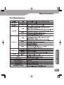
2-4 Specifications
31
Supplementar
y
Supplementary
Supplementar
y:
Supplementary
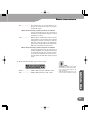
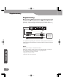
Outputting Component signals (optional)
When you connect the ADVC-1000 with the conversion cable
(optional), component signal can be output. (Functions exclusively)
For questions regarding the conversion cable, please contact your
local Canopus office, distributor or the store that you have purchased
this product.
NOTE
Analog audio output is unbalanced audio.
Supplementar
y
Supplementary
32
When you input the audio output to a balanced audio, use any of
the following methods and adjust it to a proper level.
* Use an Unbalance to Balance converter
* Adjust the input level of VTR
* Adjust the audio level of Timeline