1
ACE500 User Manual
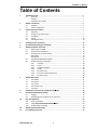
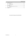
Table of Contents
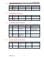
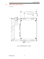
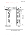
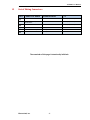
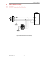
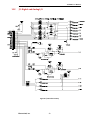
1 ACE500 Controller ……………………………………………………………………………………………………….… 5 1.1 Overview ………….……………................................................................................... 5 Software .………….…………………………………………………………………………………………….. 5 Parameters & Variables ……………………………………………………………………………….…. 5 ACE500 Introduction ..…..………………………….………………………………………………………..…….… 6 2.1 Amplifier ……………………………………………………………………………………………………….. 6 2.2 Theory of Operation …………………………………………..………………………………………….. 6 Product Safety Precautions ………………………………………………………………………………….……… 7 3.1 Operation …………………………………………………………………………………………………….…. 7 3.2 Storage and Transportation ……………………………………………………………………….…… 9 3.3 Installation …………………………………………………………………………………………….……….. 9 3.4 Wiring …………………………………………………………………………………………………………….. 10 3.5 Life Support Policy ………………………………………………………………………………………….. 10 Checking Product on Delivery ……………………………………..………………………………………………. 11 Recommended Cabling and Installation ………………………………………………………………………. 12 ACE500 Installation and Setup ……………………………………………………………………………………… 13 6.1 Mounting the ACE500 …………………………………………………………………………………….. 14 6.2 Environmental Conditions ………………………………………………………………………………. 14 6.3 Installation in the Control Panel ……………………………………………………………………… 14 Base Mount ……………………………………………………………………………………………………. 14 Rack Mount …………………………………………………………………………………………………….. 14 6.4 Simplified ACE500 Block Diagram ……………………………………………………………….….. 15 6.5 ACE500 Connector Description ……………………..………………………………………………... 16 6.5.1 J1: RS232 ……………….………………………………………………………………………….. 16 6.5.2 J2: I/O ……………………………………………………………………………………..…………. 17 6.5.3 J3: Motor Feedback …………………………………………………………………………… 18 6.5.4 J4: CAN …………………………………………………………………………………….………… 19 6.5.5 P1: Power Input …………………………………………………………………………………. 19 6.5.6 P2: External Shunt/Capacitance ………………………………………………………… 20 6.5.7 P3: Motor Phase ………………………………………………………………………………... 20 ACE500 Status LED’s ……………………………………………………………………………………………………… 21 7.1 User Ready ……………………………………………………………………………….………………….….. 21 7.2 User Power ……………………………………………………………………………………………………… 22 7.3 Line Power ……………………………………………………………………………………………………... 22 7.4 Line Current Limit ……………………………………………………………………………………………. 22 7.5 Line Shunt ……………………………………………………………………………………………………….. 22 2 3 4 5 6 7 8 9 10 10 12 Introduction to ElectroCraft CompletePower™ Plus …………………………………………………… 23 Recommended Minimum Hookup ……………………………………………………………………………….. 24 9.1 Diagram ………………………………………………………………………………………………………….. 24 9.2 Wiring Diagrams for Optional User Interfaces ………………………………………………… 25 First Time Operation …………………………………………………………………………………………………….. 26 10.1 Phasing the Motor …………………………………………………………………………………………… 26 10.2 Using ElectroCraft CompletePower™ Plus ………………………………………………………. 26 10.3 ACE500 Electrical Ratings ……………………………………………………………………………….. 27 ACE500 Dimensional Drawing ……………………………………………………………………………………… 29 List of Mating Connectors …………………………………………………………………………………………….. 31 ElectroCraft, Inc.
3