1
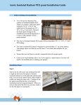
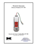
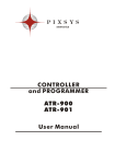
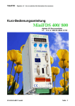
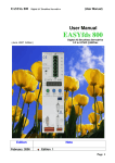
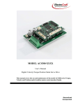
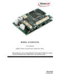
PLC
PL - 300
User Manual
Contents list
1. Data acquisition module PL300 ........................................................................ 3
1.1 Introduction .................................................................................................... 3
1.2 Frontal panel ................................................................................................... 5
1.3 Size and installation........................................................................................ 6
1.4 Electrical wirings ............................................................................................ 7
1.4.1 Examples of sensors connections to analog inputs PL300 .................... 10
1.4.2 Example of connection to RS485 and to a Master unit ......................... 11
1.5 Select type of linear output ........................................................................... 12
1.6 Communication address ............................................................................... 13
1.7 List of configuration parameters .................................................................. 14
1.8 Configuration of alarms for analog inputs .................................................... 23
1.9 Tuning (Automatic setting of PID parameters) ............................................ 26
1.10 Protocol Modbus RTU .............................................................................. 27
1.11 Addresses WORD/BIT PL300 for Modbus RTU ...................................... 28
1. Data acquisition module PL300
1.1 Introduction
The module PL300 is a powerful data acquisition module which can be used as I/O
interface for Industrial terminals or SCADA
It allows to measure temperature values with different types of thermocouples and
thermoresistance and/or it enables the acquisition of normalized signals by means
of a 14 bit converter. The 6 digital inputs can get eventual alarm notices and the 2
linear outputs (isolated 14 bit) can drive different types of transducers. Twelve
relay outputs (2 relays 8A + 10 relays 5A / 230VAC resistive) are available.
Beside the mixed acquisition system, a great advantage of this module PL300,
compared to any PC board, is the possibility to place it close to the plant and let it
communicate with the central unit via RS485 or Current loop 20mA (both
interfaces are galvanic isolated). This means a higher immunity to any external
noise, beside the possibility to simplify the wirings.
The module has been designed and built in compliance with current CE standards
and it widely meets the safety requirements for light and heavy industry.
General features
Operating
0-45 °C, humidity 35..95rH%
conditions
Box
Standard DIN 43880 for DIN rail EN500200
Self-extinguish Noryl 94V1
Protection
Box IP30, Terminal blocks IP20
Weight
About 400 gr.
Size
90 x 160x53 (depht) mm
Hardware data
Power supply
Analog inputs
(selectable via
software)
Digital inputs
12 … 24 Vac/Vdc 10VA (with AC supply, please use a
separate isolation transformer 20VA for each module)
AN1÷AN4
- Thermocouples K, S, T, R, J, E
- Thermoresistance PT100, NI100,
PT500,PT1000
(accuracy 0.2% ± 1 digit)
- Voltage 0-1V,0-10V,0-50mV
(accuracy 0.2% ± 1 digit)
- Current 0-20mA, 4-20mA
- (accuracy 0.1% ± 1 digit)
I5÷I10
- PNP
Relay outputs1
U1÷U12
U1÷U2 relay 8A-230Vac
(contact NO and NC)
- U3÷U12 relay 5A-230 Vac
Uscite SSR2
SSR1÷SSR4 - Supply 10-32 Vdc
- Max 100mA for single output
Configurable linear
OUT1÷OUT2 - Logic 0-14V (20mA max.)
outputs
- Voltage 0-10V (12bit/20mA max.)
(selectable via software
- Current 4-20mA (12bit)
and by internal dipGalvanic isolated from power and from
switch)
inputs, but not isolated themselves
Serial port
COM1
- RS485 available on terminal block
and plug connector/ 8 poles
Galvanic isolated
COM2
RS232 MODBUS on plug
connector 8 poles (not isolated)
Software data
PID and ON/OFF algorithms
Motorised valves control
Time proportioning output
Comunication protocol
-
Up to 4 control loops ON/OFF control or PID
withAutotuning function (automatic setting of PID
parameters)
Using two coupled relay outputs (U1-U2, U3-U4,
U5-U6, U7-U8) it is possible to drive the opening
of motorised valves. Position control is performed
by measuring the time of opening and closing
impulses.
In case any value is controlled applying ON/OFF
modulation, some outputs can be activated for
time-proportioning ON/OFF operating: period
(sec.) and duty-cycle of output signal must be
defined and the PL300 generates it automatically
Modbus RTU.
Selectable Baud-rate and answer delay
1
2
U1÷U4 available only on PL300-10AD
Available only on PL300-30AD.
1.2 Frontal panel
1
2
RUN- COM
0UT
IN
[1 ..6 ]
[7..12 ]
[1 ..5 ]
[6..10 ]
PL300
by PIXSYS
SLAVE #
1
3
Reference
1
2
3
Description
Plug connector – comunication COM1, COM2
RUN green led
• ON when PL300 is working
• Fast flashing (0,2sec ON /0,2sec OFF) if main program is not
available and only boot program is stored on PL300
COM led yellow
• ON for 50ms during transmission of frames on serial ports
• ON during the programming (update of main program)
OUT 1..12 red leds ON if output is active
IN 1..10 green leds ON if digital input is active, blinking led for
analog input out of range.
Slave number of module PL300.
1.3 Size and installation
46 47 48 49
37 38 39 40 41 42 43 44 45
28 29 30 31 32 33 34 35 36
6
10 11 12 13 14 15 16 17 18
19 20 21 22 23 24 25 26 27
1
2
3
4
5
7
8
9
45
90
RT1
43
53
5
Attacco a guida DIN EN50022
Din rail mounting guide EN50022
160 mm
1.4 Electrical wirings
N°
1
Name
+
2
25
C
26
A
27
B
22
23
24
AN1+
AN1AN1C
19
20
21
AN2+
AN2AN2C
15
16
17
AN3+
AN3AN3C
12
13
14
AN4+
AN4AN4C
3
6
9
18
COM
INPUT
Description
Supply 12÷24V AC\DC 10VA. To improve immunity to
noises, the employ of the dedicated transformer secondary
is highly recommended.
Reference signal of serial Use these terminals to
comunication port
expand serial connection on
applications requiring more
than one module PL300. In
RS485- / C.L.20mA+
case of comunication via
RS485, connect all terminals
C of various PL300 as well
RS485+ / C.L.20mAas terminals A and B.
Positive signal for analog input AN1 (+Tc).
Reference signal analog input AN1 (-Tc).
Compensation PT100. For 3-wire PT100 connect
compensation wire to this terminal.
Positive signal for analog input AN2 (+Tc).
Reference signal for analog input AN2 (-Tc).
Compensation PT100. For 3-wire PT100 connect
compensation wire to this terminal.
Positive signal for analog input AN3 (+Tc).
Reference signal for analog input AN3 (-Tc).
Compensation PT100. For 3-wire PT100 connect
compensation wire to this terminal.
Positive signal for analog input AN4 (+Tc).
Reference signal for analog input AN4 (-Tc)
Compensation PT100. For 3-wire PT100 connect
compensation wire to this terminal.
Common positive signal for digital inputs. Connect this
signal to one of the digital inputs (I5÷I10) or to terminal
“+” of analog inputs (AN1÷AN4 if configured via software
as digital input), to activate the input (the relevant led
switches on). These pins may be used to provide power
supply to analog sensors (voltage or current)
Input voltage is not stabilized.
N°
11
10
8
7
5
4
Name
I5
I6
I7
I8
I9
I10
28
29
30
31
32
33
34
35
36
37
38
39
40
41
42
43
44
45
46
47
48
49
PL300-10AD
U1 Com
U1 N.C.
U1 N.O.
U2 Com
U2 N.C.
U2 N.O.
U3÷U7 Com
U3 N.O.
U4 N.O.
U5 N.O.
U6 N.O.
U7 N.O.
U8÷U12Com
U8 N.O.
U9 N.O.
U10 N.O.
U11 N.O.
U12 N.O.
OUT1+
OUT1OUT2+
OUT2-
Description
Digital input
Digital input
Digital input
Digital input
Digital input
Digital input
To activate digital inputs,
short-circuit signal COM
INPUT on the terminals of
input. Leds ON mean that
output is active
Version 12 relay outputs
Common contact relay U1.
Contact relay U1 N.C.
Contact relay U1 N.O.
Common contact relay U2.
Contact relay U2 N.C.
Contact relay U2 N.O.
Common contact relays U3÷U7.
Contact relay U3 N.O.
Contact relay U4 N.O.
Contact relay U5 N.O.
Contact relay U6 N.O.
Contact relay U7 N.O.
Common contact relays U8÷U12.
Contact relay U8 N.O.
Contact relay U9 N.O.
Contact relay U10 N.O.
Contact relay U11 N.O.
Contact relay U12 N.O.
Positive signal linear output OUT1.
Reference linear output OUT1.
Positive signal linear output OUT2
Reference linear output OUT2
8A ÷ 230Volt
resistive
5A ÷ 230Volt
resistive
0..10 Volt
4..20 mA
Logic 0-15 Volt
No.
28
29
30
31
32
33
35
36
34
37
38
39
40
41
42
43
44
45
46
47
48
49
3
PL300-30AD Version 8 relay outputs + 4 SSR outputs
Name
Description
No connection
--Output SSR no. 2 (NPN).
SSR2
Output SSR no. 1 (NPN).
SSR1
100mA ÷ 24Volt
No connection
Max.
--Output SSR no. 4 (NPN).
SSR4
Output SSR no. 3 (NPN).
SSR3
Positive signal for SSR outputs.
3
12/24V
10 ÷ 32 Vdc
Reference signal for SSR outputs.
U5÷U7 Com Common contact relays U5÷U7.
Relay U5 contact N.O.
U5 N.O.
Relay U6 contact N.O.
U6 N.O.
Relay U7 contact N.O.
U7 N.O.
5A ÷ 230Volt
U8÷U12Com Common contact for relays U8÷U12.
resistive
Relay U8 contact N.O.
U8 N.O.
Relay U9 contact N.O.
U9 N.O.
Relay U10 contact N.O.
U10 N.O.
Relay U11 contact N.O.
U11 N.O.
Relay U12 contact N.O.
U12 N.O.
Positive OUT1 linear
OUT1+
0..10 Volt
Reference OUT1 linear
OUT14..20 mA
Logic 0-15 Volt
Positive OUT2 linear
OUT2+
Reference OUT2 linear
OUT2-
Up to max. 80 mA, to supply SSR outputs it is possible to use the common
positive signal of digital inputs (pins 3,6,9,18) and the negative signal of general
power supply (pin 2).
No.
Name
COM1
RS485
Description
PL250 8
COM
plug-8 1
87654 - COM1-A RS- (MORS. 26)
32 - COM1-C RS REF (MORS. 25)
1 - COM1-B RS+ (MORS. 27)
COM1
RS485
COM
COM2
RS232
PL250 8
COM
plug-8 1
876 - COM2- RX232
5 - COM2- TX232
43 - COM2- GND232
21-
COM2
RS232
1.4.1 Examples of sensors connections to analog inputs PL300
V+
+
(18)
V(2)
V+
+
(18)
-
1.4.2 Example of connection to RS485 and to a Master unit
USARE CAVO SCHERMATO TWISTATO
- + REF
220 ohm
1.5 Select type of linear output
PL300 is provided with 2 linear outputs (OUT1, OUT2) which must be configured
via software and manually by configuring 2 dip-switches on board:
• Disconnect power supply PL300.
• Use a screwdriver to remove the upper cover of PL300
• Set dip SW1 (for OUT1) and SW2 (for OUT2) as shown here below to
configure the output
•
•
Replace the upper cover and restart PL300.
Dip SW1-1 and SW2-1 are used to set the communication address of PL300,
not for outputs selection.
12
1.6 Communication address
Two dip-switches allow to set the address of module PL300 to communicate with a
Master device. Four combinations of jumpers are available, therefore to connect
more than 4 modules to the network it is necessary to modify the value of offset
parameter. The address of the module is given as follows:
MODULE ADDRESS = ADDRESS OFFSET + COMBINATION OF DIPSWITCHES
The address offset is stored on memory of PL300 (default is 0) and it can be
modified on Modbus word 5.
To set the address proceed as follows:
• Disconnect power supply
• Remove upper cover of PL300
• Set dip SW1-1 and SW2-1 as described below : the obtained value must be
added to offset value in order to get the complete address.
•
Place cover and restart PL300.
13
1.7 List of configuration parameters
Configuration parameters are stored on EEPROM, therefore they will not be lost in
case of power failure. Each parameter can be written max. 100.000 times, therefore
avoid useless writings of parameters. At each modify of parameters, PL300 starts
the inizialization both of inputs reading and outputs rate. This stage lasts about 2
seconds. Some parameters are handled as hexadecimal digits: the parameter is
divided into 4 nibbles (groups of 4 bit) to be represented.
“1st digit” = bits 12÷15
“2nd digit”= bits 8÷11
“3rd digit” =bits 4÷7
“4th digit”= bits 0÷3 ( bit 0 is meant as less significant)
P-01
P-02
P-03
P-04
Configuration analog input AN1
Configuration analog input AN2
Configuration analog input AN3
Configuration analog input AN4
These parameters define the type of sensor connected to analog input AN1,
AN2, AN3 , AN4.
No connected sensor ( Input used as digital input)
0
Type K (-270/1370°C)
1
Type S (-50/1760°C)
2
Type T (-270/400°C)
3
Type R (-50/1760°C)
4
Type J (-210/1200°C)
5
Type E (-270/1000°C)
6
PT100 (-200/800°C)
7
NI100 (-60/180°C)
8
--------------9
10 Voltage 0..1V
11 Voltage 0..10V
12 Current 0..20mA
13 Current 4..20mA
14 Voltage 0..50mV
15 PT500 with resistor 506 Ohm 0,1% parallel (-200/350°C)
16 NI1000 with resistor 470 Ohm 0.1% parallel (-60/150°C)
P-05 Lower limit scale AN1 (-3000.0 ÷ 3000.0)
P-06 Upper limit scale AN1 (-3000.0 ÷ 3000.0)
These parameters define the numeric limits of analog conversion for signal
connected to AN1 (only if configured for current/voltage).
14
P-07 Lower limit scale AN2 (-3000.0 ÷ 3000.0)
P-08 Upper limit scale AN2 (-3000.0 ÷ 3000.0)
These parameters define the numeric limits of analog conversion for signal
connected to AN2 (only if configured for current or voltage).
P-09 Lower limit scale AN3 (-3000.0 ÷ 3000.0)
P-10 Upper limit scale AN3 (-3000.0 ÷ 3000.0)
These parameters define the numeric limits of analog conversion for signal
connected to AN3 (only if configured for current/voltage).
P-11 Lower limit scale AN4 (-3000.0 ÷ 3000.0)
P-12 Upper limit scale AN4 (-3000.0 ÷ 3000.0)
These parameters define the numeric limits of analog conversion for signal
connected to AN4 (only if configured for current/voltage)
P-13 Calibration OFFSET AN1 (-999.9 ÷ 999.9)
P-14 Calibration GAIN AN1 (-999.9 ÷ 999.9%)
P-15 Calibration OFFSET AN2 (-999.9 ÷ 999.9)
P-16 Calibration GAIN AN2 (-999.9 ÷ 999.9%)
P-17 Calibration OFFSET AN3 (-999.9 ÷ 999.9)
P-18 Calibration GAIN AN3 (-999.9 ÷ 999.9%)
P-19 Calibration OFFSET AN4 (-999.9 ÷ 999.9)
P-20 Calibration GAIN AN4 (-999.9 ÷ 999.9%)
These parameters define the calibration for conversion of AN1, AN2, AN3,
AN4 to correct any eventual reading mistake. The relative formule is as
follows:
Value AN1 = Value AN1 + (Value AN1 * GAIN calibration AN1) / 100.0
+ OFFSET Calibration
P-21 Software filter (1..20sec)
Filter value on conversion of AN1, AN2, AN3 , AN4
P-22 Type of linear output OUT1
P-23 Type of linear output OUT2
Type of used linear output. Set the dip-switches correctly. Time for SSR
output is set on P-24 (OUT1) and P-25 (OUT2).
Not used
0
Logic 0-14V(30mA)
1
Voltage 0...10V
2
Current 4..20mA
3
-------------------4
SSR time proportioning (Period is set on parameters P-24 / P-25)
5
15
P-24 Time for servo-control 1 (0..600 sec.)
Time for servo-control related to Open/Close U1,U2 or period for time
proportioning output U1(U2) or SSR1 or OUT1 (see P-28)
P-25 Time for servo-control 2 (0..600 sec.)
Time for servo-control related to Open/Close U3,U4 or period for time
proportioning output U3(U4) or SSR2 or OUT2 (see P-29)
P-26 Time for servo-control 3 (0..600 sec.)
Time for servo-control related to Open/Close U5,U6 or period for time
proportioning output U5(U6) or SSR3 (see P-30)
P-27 Time for servo-control 4 (0..600 sec.)
Time for servo-control related to Open/Close U7,U8 or period for time
proportioning output U7(U8) or SSR4 (see P-31)
P-28 SERVO-CONTROL1 Operating mode for relay output U1,U2 or SSR1
Desabled (U1-U2 or SSR1 free)
0
Combined operating of U1-U2 for function OPEN (U1)-CLOSE (U2)
1
Time proportioning U1 with contact N.O.
2
U2 free
Time proportioning U1 with contact N.O.
3
Time proportioning U2 with contact N.C
U1 ON/OFF + contact N.O.
4
U2 free
U1 ON/OFF + contact N.C.
5
U2 free
SSR1 time proportioning
6
SSR1 ON/OFF
7
P-29 SERVO-CONTROL2 Operating mode for relay output U3,U4 or SSR2
Desabled (U3 – U4 or SSR2 free)
0
Combined operating of U3-U4 for function OPEN (U3)-CLOSE (U4)
1
Time proportioning U3 with contact N.O.
2
U4 free
Time proportioning U3 with contact N.O.
3
Time proportioning U4 with contact N.C.
U3 ON/OFF + contact N.O.
4
U4 free
U3 ON/OFF + contact N.C.
5
U4 free
SSR2 time proportioning
6
SSR2 ON/OFF
7
16
P-30 SERVO-CONTROL3 Operating mode for relay output U5,U6 or SSR3
Desabled (U5, U6 or SSR3 free)
0
Combined action of U5-U6 for function OPEN (U5)-CLOSE (U6)
1
Time proportioning U5 with contact N.O.
2
U6 free
Time proportioning U5 with contact N.O.
3
Time proportioning U6 with contact N.C.
U5 ON/OFF + contact N.O.
4
U6 free
U5 ON/OFF + contact N.C.
5
U6 free
SSR3 time proportioning
6
SSR3 ON/OFF
6
P-31 SERVO-CONTROL4 Operating mode for relay output U7,U8 or SSR4
Desabled (U7, U8 or SSR4 free)
0
Combined action of U7-U8 for function OPEN (U7)-CLOSE (U8)
1
Time proportioning U7 with contact N.O.
2
U8 free
Time proportioning U7 with contact N.O.
3
Time proportioning U8 with contact N.C.
U7 ON/OFF + contact N.O.
4
U8 free
U7 ON/OFF + contact N.C.
5
U8 free
SSR4 time proportioning
6
SSR4 ON/OFF
7
P-32 State of relay in off-line condition
State of relays in case of comunication failure with MASTER for over 60
seconds. Each bit of this parameter is related to the state of one relay:
Bit0 U1, Bit1 U2, ... Bit11U12.
Value 65535 desables this function.
Open contact
0
Closed contact
1
17
P-33 Configuration serial port COM1 (RS-485)
Switch off and restart the PL300 after entering of these settings.
1st Digit – BaudRate communication COM1
9600 bits/sec
0
19200 bits/sec
1
38400 bits/sec
2
2nd Digit – Data format for COM1
8,N,1
0
8,O,1
1
8,E,1
2
8,N,2
3
8,O,2
4
8,E,2
5
P-34 Answer delay COM1 (RS-485) 0..1000 msec
Set the minimum delay between end of serial reception of data from
master and start of answer transmission from PL300.
P-35 Reserved
P-36 Control action on analog inputs
1st Digit – Control action analog input AN1
2nd Digit – Control action analog input AN2
3rd Digit – Control action analog input AN3
4th Digit – Control action analog input AN4
No control action
0
ON/OFF
1
P.I.D. direct (ex.: cooling)
2
P.I.D. reverse (ex.: heating)
3
18
P-37 Control outputs
1st Digit – Control output AN1analog input
Servo-control 1 (see parameter P-28)
0
OUT1 (see parameter P-22)
1
OUT2 (see parameter P-23)
2
2nd Digit – Control output AN2 analog input
Servo-control 2 (see parameter P-29)
0
OUT1 (see parameter P-22)
1
OUT2 (see parameter P-23)
2
3rd Digit – Control output AN3 analog input
Servo-control 3 (see parameter P-30)
0
OUT1 (see parameter P-22)
2
OUT2 (see parameter P-23)
3
4th Digit – Control output AN4 analog input
Servo-control 4 (see parameter P-31)
0
OUT1 (see parameter P-22)
2
OUT2 (see parameter P-23)
3
P-38 Dead band PID control (or hysteresis ON/OFF ) AN1 (-999.9÷999.9)
P-39 Proportional band PID control AN1 (-999.9÷999.9)
P-40 Integral time PID control AN1 (0÷10000 sec)
P-41 Dearivative time PID control AN1 (0÷1000.0 sec)
P-42 Dead band PID control (or hysteresis ON/OFF ) AN2 (-999.9÷999.9)
P-43 Proportional band PID control AN2 (-999.9÷999.9)
P-44 Integral time PID control AN2 (0÷10000 sec)
P-45 Derivative time PID control AN2 (0÷1000.0 sec)
P-46 Dead band PID control (or hysteresis ON/OFF ) AN3 (-999.9÷999.9)
P-47 Proportional band PID control AN3 (-999.9÷999.9)
P-48 Integral time PID control AN3 (0÷10000 sec)
P-49 Derivative time PID regolazione AN3 (0÷1000.0 sec)
P-50 Dead band PID control (or hysteresis ON/OFF ) AN4 (-999.9÷999.9)
P-51 Proportional band PID control AN4 (-999.9÷999.9)
P-52 Integral time PID control AN4 (0÷10000 sec)
P-53 Derivative time PID control AN4 (0÷1000.0 sec)
P-54 Use of variables on non-volatile RAM
1st Digit – Enable the functions related to words 164÷175
Functions desabled
0
Functions enabled
1
2nd Digit – Enable the functions related to words 176÷179
Functions desabled
0
Functions enabled
1
19
P-55 Starting % output OUT1 (0.00÷100.00 %)
P-56 Starting % output OUT2 (0.00÷100.00 %)
P-57 Configuration of alarms for analog inputs AN1, AN2
1st Digit – Configuration 1st alarm analog input AN1
2nd Digit – Configuration 2nd alarm analog input AN1
3rd Digit – Configuration 1st alarm analog input AN2
4th Digit – Configuration 2nd alarm analog input AN2
Desabled
0
Independent alarm / over
1
Independent alarm / under
2
Upper deviation
3
Lower deviation
4
Band alarm / inside
5
Band alarm / outside
6
Lower deviation alarm desabled at starting
7
(Alarm is automatically enabled when value of analog input
exceeds the alarm treshold added to value of hysteresis).
P-58 Configuration of alarms for analog inputs AN3, AN4
1st Digit – Configuration 1st alarm analog input AN3
2nd Digit – Configuration 2nd alarm analog input AN3
3rd Digit – Configuration 1st alarm analogal input AN4
4th Digit – Configuration 2nd alarm analog input AN4
Disabled
0
Independent alarm / over
1
Independent alarm / under
2
Upper deviation
3
Lower deviation
4
Band alarm / inside
5
Band alarm / outside
6
Lower deviation alarm desabled at starting
7
(Alarm is automatically enabled when value of analog input
exceeds the alarm treshold added to value of hysteresis).
20
P-59 Configuration of alarm outputs for analog inputs AN1, AN2∗
1st Digit – 1st alarm analog input AN1
2nd Digit – 2nd alarm analog input AN1
3rd Digit – 1st alarm analog input AN2
4th Digit – 2nd alarm analog input AN2
No output
0
U1/SSR1
1
U2/SSR2
2
U3/SSR3
3
U4/SSR4
4
U5
5
U6
6
U7
7
U8
8
U9
9
10 U10
11 U11
12 U12
13 OUT1
14 OUT2
P-60 Configuration of alarm outputs for analog inputs AN3, AN4∗
1st Digit – Output configuration for 1st alarm analog input AN3
2nd Digit – Output configuration 2nd alarm analog input AN3
3rd Digit – Output configuration 1st alarm analog input AN4
4th Digit – Output configuration 2nd alarm analog input AN4
No outputs
0
U1/SSR1
1
U2/SSR2
2
U3/SSR3
3
U4/SSR4
4
U5
5
U6
6
U7
7
U8
8
U9
9
10 U10
∗
Realy outputs U1÷U4 are available on PL300-1XAD (12 relay OUT),
SSR1÷SSR4 outputs are available on PL300-3XAD (4 SSR + 8 relay OUT).
21
P-61
P-62
P-63
P-64
P-65
P-66
P-67
P-68
P-69
P-70
P-71
P-72
P-73
P-74
P-75
P-76
P-77
P-78
P-79
P-80
P-81
11 U11
12 U12
13 OUT1
14 OUT2
Treshold 1st alarm analog input AN1 (-3000.0 ÷ 3000.0)
Hysteresis 1st alarm analog input AN1 (0.0 ÷ 999.9)
Treshold 2nd alarm analog input AN1 (-3000.0 ÷ 3000.0)
Hysteresis 2nd alarm analog input AN1 (0.0 ÷ 999.9)
Treshold 1st alarm analog input AN2(-3000.0 ÷ 3000.0)
Hysteresis 1st alarm analog input AN2 (0.0 ÷ 999.9)
Treshold 2nd alarm analog input AN2 (-3000.0 ÷ 3000.0)
Hysteresis 2nd alarm analog input AN2 (0.0 ÷ 999.9)
Treshold 1st alarm analog input AN3 (-3000.0 ÷ 3000.0)
Hysteresis 1st alarm analog input AN3 (0.0 ÷ 999.9)
Treshold 2nd alarm analog input AN3 (-3000.0 ÷ 3000.0)
Hysteresis 2nd alarm analog input AN3 (0.0 ÷ 999.9)
Treshold 1st alarm analog input AN4 (-3000.0 ÷ 3000.0)
Hysteresis 1st alarm analog input AN4 (0.0 ÷ 999.9)
Treshold 2nd alarm analog input AN4 (-3000.0 ÷ 3000.0)
Hysteresis 2nd alarm analog input AN4 (0.0 ÷ 999.9)
Define state and setpoint for control action on analog inputs
1st digit – Control action for analog input AN1
2nd digit – Control action for analog input AN2
3rd digit – Control action for analog input AN3
4th digit – Control action for analog input AN4
Control action is defined by bit no. 600, 601, 602 , 603 and by
0
setpoint values written on words no. 158, 159, 160 ,161.
Start/stop of control action and modify of setpoints both
available via serial communication.
Control action always activated. Setpoint values written on
1
parameters P-78, P-79, P-80 e P-81. Select this option if modify
of setpoints by the operator is not required.
Control action always activated. Setpoint values written on
2
words no. 158, 159, 160, 161 and changeable via serial
communication.
Control setpoint for analog input AN1 (-3000.0 ÷ 3000.0)
Control setpoint for analog input AN2 (-3000.0 ÷ 3000.0)
Control setpoint for analog input AN3 (-3000.0 ÷ 3000.0)
Control setpoint for analog input AN4 (-3000.0 ÷ 3000.0)
22
1.8 Configuration of alarms for analog inputs
For each analog input, two alarms can be used and their operating is depending on
the values of parameters P-57 to P-76. The tables below show the different
operatings available for alarms.
INDEPENDENT ALARM / OVER
ALARM SOURCE
ALARM TRESHOLD
ALARM
HYSTERESIS
Max. treshold for the alarm source
(one of the analog inputs).
TIME
ON
OFF
INDEPENDENT ALARM / UNDER
ALARM SOURCE
ALARM
HYSTERESIS
ALARM TRESHOLD
ALARM
ON
OFF
TIME
23
Minimum treshold for the alarm
source.
DEVIATION HIGH ALARM
ALARM SOURCE
ALARM TRESHOLD
ALARM
HYSTERESIS
SPV
ALARM
ON
OFF
TIME
DEVIATION LOW ALARM
ALARM SOURCE
ALARM TRESHOLD
SPV
ALARM
HYSTERESIS
ALARM
ON
OFF
TIME
BAND ALARM / INSIDE
ALARM SOURCE
ALARM TRESHOLD
SPV
ALARM
HYSTERESIS
ALARM
ON
OFF
TIME
24
BAND ALARM / OUTSIDE
ALARM SOURCE
ALARM TRESHOLD
SPV
ALARM
HYSTERESIS
ALARM
ON
OFF
TIME
DEVIATION LOW ALARM - DESABLED AT STARTING
ALARM SOURCE
ALARM TRESHOLD
SPV
ALARM
HYSTERESIS
ALARM
ON
OFF
DISABLE
TIME
25
This alarm is desabled at the
starting of PL300 and it is
automatically activated when the
alarm source exceeds the alarm
treshold of a value which is equal
to the hysteresis. Then the alarm
works like the above described
“deviation low alarm”.
1.9 Tuning (Automatic setting of PID parameters)
In Tuning action the characteristics of the controller are matched to those of the
process being controlled in order to obtain:
-stable “straight-line” control of the temperatre at setpoint without fluctuations
-no overshoot or undershoot of the temperature at setpoint
-quick response to deviations from the setpoint caused by external disturbances,
thereby restoring the temperature rapidly to the setpoint value
Tuning involves calculating and setting the value of the following parameters:
•
Proportional band (The bandwidth in display units over which the output
power is proportioned between minimum and maximum )
•
Integral time (determines the time taken by the controller to remove steadystate error signals)
•
Derivative time (determines how strongly the controller will react to the rateof-change of the measured value)
•
Servo-control time (determines the cycle time for time proportioning output)
For management of motorized valves (Open/Close), time is not rated.
26
1.10 Protocol Modbus RTU
Module PL300 is conceived for connection to SCADA systems or Terminals via
Modbus RTU. Serial communication enables the programming of parameters,
configuration of I/O, reading of analog/digital inputs and outputs control.
8 - AC/DC
7 - + OUT
6 - RX-232 (3 DB9-F)
5 - TX-232 (2 DB9-F)
4-A
3 - GND-232 (5 DB9-F)
2-C
1-B
PL300 8
COM1
plug-8 1
Features of protocol Modbus RTU
Baud-rate
COM1 ->9600 baud (Default: see parameter P-33)
COM2 ->19200 baud
Format
8,N,1 = 8bit, no parity, 1stop ( (Default: see parameter P-33)
Supported functions BITS READING
(0x01, 0x02)
WORDS READING (max 30 word)
(0x03, 0x04)
SINGLE BIT WRITING
(0x05)
SINGLE WORD WRITING
(0x06)
MULTIPLE BITS WRITING
(0x0F)
MULTIPLE WORDS WRITING (max 30 word)
(0x10)
Error codes
ILLEGAL FUNCTION CODE
(0x01)
ILLEGAL DATA ADDRESS
(0x02)
ILLEGAL DATA VALUE
(0x04)
Broadcast
Simultaneous writing to all connected slaves by address
0x00 , no answer from slaves
Polling of unknown Polling address 0xFF ; any connected slave answers.
slave address
27
1.11 Addresses WORD/BIT PL300 for Modbus RTU
The following tables contain all data (words and bits) which may be handled by
Modbus protocol. The tables report reading and writing features as well as the
value assumed at the starting of PL300. According to inizialization value assumed
at starting, the following type of value are possible:
1.
2.
3.
4.
“EEP” value stores on Eeprom memory and kept also in case of power
failure
“TAMP” value stored on non-volatile RAM memory. Also these data are
stored in case of power failure (approx. 4 months)
“?”
These values are not given at the starting of PL300
Numeric value: the value assumed at starting of PL300 is the one which is
reported in the table.
WORD
MODBUS
ADDRESS
0
1
5
96
97
98
99
100
101
102
103
104
105
106
107
Description
Type of device
Software version PL300
Slave address MODBUS protocol
Value of linear output OUT1 (Range 0-10000)
Value of linear output OUT2 (Range 0-10000)
Serial transmission counter
Reset monitor (force to “0” at reset)
Value analog input AN1
Value analog input AN2
Value analog input AN3
Value analog input AN4
Value digital inputs (bit0 I1,..., bit9 I10)
Status relay outputs (bit0 U1,..., bit11 U12)
Temperature cold junction PL300
Flag for module status (1 = error/fail)
Bit 0 input AN1 out of range
Bit 1 input AN2 out of range
Bit 2 input AN3 out of range
Bit 3 input AN4 out of range
Bit 4 internal eeprom error
Bit 5 error on configuration parameters
Bit 6 error on calibration parameters
Bit 7 error on RAM memory data (TAMP)
Bit 8 error internal clock
28
READ/ RESET
WRITE VALUE
R
R
R/W
R
R
R/W
R/W
R
R
R
R
R
R
R
R
20
100
EEP
P-55
P-56
0
0
?
?
?
?
?
?
?
?
WORD
MODBUS
ADDRESS
Description
108
Alarms status analog inputs (bit0 alarm no.1 AN1,
bit1 alarm no.2 AN1,..., bit7 alarm no.2 AN4)
Timer (minutes) for closing of relay U1/SSR1
Timer (minutes) for closing of relay U2/SSR2
Timer (minutes) for closing of relay U3/SSR3
Timer (minutes) for closing of relay U4/SSR4
Timer (minutes) for closing of relay U5
Timer (minutes) for closing of relay U6
Timer (minutes) for closing of relay U7
Timer (minutes) for closing of relay U8
Timer (minutes) for closing of relay U9
Timer (minutes) for closing of relay U10
Timer (minutes) for closing of relay U11
Timer (minutes) for closing of relay U12
Setting of servo control 1 output (Range 0-10000)
Setting of servo control 2 output (Range 0-10000)
Setting of servo control 3 output (Range 0-10000)
Setting of servo control 4 output (Range 0-10000)
Setting of linear output OUT1 (Range 0-10000)
Setting of linear output OUT2 (Range 0-10000)
Setting relay outputs (bit0 U1,..., bit11 U12)
Enable relay modify via serial communication
1 enable, 0desable
bit0 U1,..., bit11 U12.
Only relays having bit=1 will assume the entered
value by parameter 156
Control setpoint AN1
Control setpoint AN2
Control setpoint AN3
Control setpoint AN4
Control Run/Stop AN1÷AN4
(bit0AN1,..., bit3AN4 1=RUN)
Start Auto-tuning AN1÷AN4 (only for reverse P.I.D.)
(bit0AN1,..., bit3AN4 1=START)
After completing the routine, PL300 will reset to 0 the
bit related to the input which has been processed.
109
110
111
112
113
114
115
116
117
118
119
120
150
151
152
153
154
155
156
157
158
159
160
161
162
163
29
READ/ RESET
WRITE VALUE
R
?
R/W
R/W
R/W
R/W
R/W
R/W
R/W
R/W
R/W
R/W
R/W
R/W
R/W
R/W
R/W
R/W
R/W
R/W
R/W
R/W
TAMP
TAMP
TAMP
TAMP
TAMP
TAMP
TAMP
TAMP
TAMP
TAMP
TAMP
TAMP
0
0
0
0
P-55
P-56
0
0
R/W
R/W
R/W
R/W
R/W
TAMP
TAMP
TAMP
TAMP
TAMP
R/W
TAMP
WORD
MODBUS
ADDRESS
164
165
166
167
168
169
170
171
172
Description
Select source analog input for control loop 1
0=AN1, 1=AN1, 2=AN2, 3=AN3, 4=AN4.
Select source analog input for control loop 2
0=AN2, 1=AN1, 2=AN2, 3=AN3, 4=AN4.
Select source analog input for control loop 3
0=AN3, 1=AN1, 2=AN2, 3=AN3, 4=AN4.
Select source analog input for control loop 4
0=AN4, 1=AN1, 2=AN2, 3=AN3, 4=AN4.
Select source setpoint for control loop 1
0 = Control setpoint AN1 (word n° 158)
1 = Control setpoint AN1 (word n° 158)
2 = Control setpoint AN2 (word n° 159)
3 = Control setpoint AN3 (word n° 160)
4 = Control setpoint AN4 (word n° 161)
Select source setpoint for control loop 2
0 = Control setpoint AN2 (word n° 159)
1 = Control setpoint AN1 (word n° 158)
2 = Control setpoint AN2 (word n° 159)
3 = Control setpoint AN3 (word n° 160)
4 = Control setpoint AN4 (word n° 161)
Select source setpoint for control loop 3
0 = Control setpoint AN3 (word n° 160)
1 = Control setpoint AN1 (word n° 158)
2 = Control setpoint AN2 (word n° 159)
3 = Control setpoint AN3 (word n° 160)
4 = Control setpoint AN4 (word n° 161)
Select source setpoint for control loop 4
0 = Control setpoint AN4 (word n° 161)
1 = Control setpoint AN1 (word n° 158)
2 = Control setpoint AN2 (word n° 159)
3 = Control setpoint AN3 (word n° 160)
4 = Control setpoint AN4 (word n° 161)
Select PID parameters for control loop 1
0=Chose PID parameters AN1
1= Chose PID parameters AN1
2= Chose PID parameters AN2
3= Chose PID parameters AN3
4= Chose PID parameters AN4
30
READ/ RESET
WRITE VALUE
R/W
TAMP
R/W
TAMP
R/W
TAMP
R/W
TAMP
R/W
TAMP
R/W
TAMP
R/W
TAMP
R/W
TAMP
R/W
TAMP
173
174
175
176
177
178
179
Select PID parameters for control loop 2
0=Chose PID parameters AN2
1= Chose PID parameters AN1
2= Chose PID parameters AN2
3= Chose PID parameters AN3
4= Chose PID parameters AN4
Select PID parameters for control loop 3
0=Chose PID parameters AN3
1= Chose PID parameters AN1
2= Chose PID parameters AN2
3= Chose PID parameters AN3
4= Chose PID parameters AN4
Select PID parameters for control loop 4
0=Chose PID parameters AN4
1= Chose PID parameters AN1
2= Chose PID parameters AN2
3= Chose PID parameters AN3
4= Chose PID parameters AN4
Minimum % output OUT1 (0.00÷100.00%)
Max. % output OUT1 (0.00÷100.00%)
Minimum % output OUT2 (0.00÷100.00%)
Max. % output OUT2 (0.00÷100.00%)
For details about the options described above, see parameter P-54.
31
R/W
TAMP
R/W
TAMP
R/W
TAMP
R/W
R/W
R/W
R/W
TAMP
TAMP
TAMP
TAMP
WORD
MODBUS
ADDRESS
200
201
202
203
204
205
206
207
208
209
210
211
212
213
214
215
216
217
218
219
220
221
222
223
224
225
226
227
228
229
230
231
232
233
234
235
236
237
Description
Configuration parameter P-01
Configuration parameter P-02
Configuration parameter P-03
Configuration parameter P-04
Configuration parameter P-05
Configuration parameter P-06
Configuration parameter P-07
Configuration parameter P-08
Configuration parameter P-09
Configuration parameter P-10
Configuration parameter P-11
Configuration parameter P-12
Configuration parameter P-13
Configuration parameter P-14
Configuration parameter P-15
Configuration parameter P-16
Configuration parameter P-17
Configuration parameter P-18
Configuration parameter P-19
Configuration parameter P-20
Configuration parameter P-21
Configuration parameter P-22
Configuration parameter P-23
Configuration parameter P-24
Configuration parameter P-25
Configuration parameter P-26
Configuration parameter P-27
Configuration parameter P-28
Configuration parameter P-29
Configuration parameter P-30
Configuration parameter P-31
Configuration parameter P-32
Configuration parameter P-33
Configuration parameter P-34
Configuration parameter P-35
Configuration parameter P-36
Configuration parameter P-37
Configuration parameter P-38
32
READ/ RESET
WRITE VALUE
R/W
R/W
R/W
R/W
R/W
R/W
R/W
R/W
R/W
R/W
R/W
R/W
R/W
R/W
R/W
R/W
R/W
R/W
R/W
R/W
R/W
R/W
R/W
R/W
R/W
R/W
R/W
R/W
R/W
R/W
R/W
R/W
R/W
R/W
R/W
R/W
R/W
R/W
EEP
EEP
EEP
EEP
EEP
EEP
EEP
EEP
EEP
EEP
EEP
EEP
EEP
EEP
EEP
EEP
EEP
EEP
EEP
EEP
EEP
EEP
EEP
EEP
EEP
EEP
EEP
EEP
EEP
EEP
EEP
EEP
EEP
EEP
EEP
EEP
EEP
EEP
WORD
MODBUS
ADDRESS
238
239
240
241
242
243
244
245
246
247
248
249
250
251
252
253
254
255
256
257
258
259
260
261
262
263
264
265
266
267
268
269
270
271
272
273
274
275
Description
Configuration parameter P-39
Configuration parameter P-40
Configuration parameter P-41
Configuration parameter P-42
Configuration parameter P-43
Configuration parameter P-44
Configuration parameter P-45
Configuration parameter P-46
Configuration parameter P-47
Configuration parameter P-48
Configuration parameter P-49
Configuration parameter P-50
Configuration parameter P-51
Configuration parameter P-52
Configuration parameter P-53
Configuration parameter P-54
Configuration parameter P-55
Configuration parameter P-56
Configuration parameter P-57
Configuration parameter P-58
Configuration parameter P-59
Configuration parameter P-60
Configuration parameter P-61
Configuration parameter P-62
Configuration parameter P-63
Configuration parameter P-64
Configuration parameter P-65
Configuration parameter P-66
Configuration parameter P-67
Configuration parameter P-68
Configuration parameter P-69
Configuration parameter P-70
Configuration parameter P-71
Configuration parameter P-72
Configuration parameter P-73
Configuration parameter P-74
Configuration parameter P-75
Configuration parameter P-76
33
READ/ RESET
WRITE VALUE
R/W
R/W
R/W
R/W
R/W
R/W
R/W
R/W
R/W
R/W
R/W
R/W
R/W
R/W
R/W
R/W
R/W
R/W
R/W
R/W
R/W
R/W
R/W
R/W
R/W
R/W
R/W
R/W
R/W
R/W
R/W
R/W
R/W
R/W
R/W
R/W
R/W
R/W
EEP
EEP
EEP
EEP
EEP
EEP
EEP
EEP
EEP
EEP
EEP
EEP
EEP
EEP
EEP
EEP
EEP
EEP
EEP
EEP
EEP
EEP
EEP
EEP
EEP
EEP
EEP
EEP
EEP
EEP
EEP
EEP
EEP
EEP
EEP
EEP
EEP
EEP
WORD
MODBUS
ADDRESS
276
277
278
279
280
Description
Configuration parameter P-77
Configuration parameter P-78
Configuration parameter P-79
Configuration parameter P-80
Configuration parameter P-81
34
READ/ RESET
WRITE VALUE
R/W
R/W
R/W
R/W
R/W
EEP
EEP
EEP
EEP
EEP
BIT
MODBUS
ADDRESS
300
301
302
303
304
305
306
307
308
309
400
401
402
403
404
405
406
407
408
409
410
411
420
421
422
423
424
425
426
427
428
429
430
431
440
441
442
443
DESCRIPTION
Status digital input I1
Status digital input I2
Status digital input I3
Status digital input I4
Status digital input I5
Status digital input I6
Status digital input I7
Status digital input I8
Status digital input I9
Status digital input I10
Status relay output U1
Status relay output U2
Status relay output U3
Status relay output U4
Status relay output U5
Status relay output U6
Status relay output U7
Status relay output U8
Status relay output U9
Status relay output U10
Status relay output U11
Status relay output U12
Setting relay output U1
Setting relay output U2
Setting relay output U3
Setting relay output U4
Setting relay output U5
Setting relay output U6
Setting relay output U7
Setting relay output U8
Setting relay output U9
Setting relay output U10
Setting relay output U11
Setting relay output U12
Enable modify relay output U1
Enable modify relay output U2
Enable modify relay output U3
Enable modify relay output U4
35
READ/ RESET
WRITE VALUE
R
R
R
R
R
R
R
R
R
R
R
R
R
R
R
R
R
R
R
R
R
R
R/W
R/W
R/W
R/W
R/W
R/W
R/W
R/W
R/W
R/W
R/W
R/W
R/W
R/W
R/W
R/W
?
?
?
?
?
?
?
?
?
?
?
?
?
?
?
?
?
?
?
?
?
?
0
0
0
0
0
0
0
0
0
0
0
0
0
0
0
0
BIT
MODBUS
ADDRESS
444
445
446
447
448
449
450
451
500
501
502
503
504
505
506
507
600
601
602
603
700
701
702
703
DESCRIZIONE
Enable modify relay output U5 via serial comm.
Enable modify relay output U6 via serial comm.
Enable modify relay output U7 via serial comm.
Enable modify relay output U8 via serial comm.
Enable modify relay output U9 via serial comm.
Enable modify relay output U10 via serial comm.
Enable modify relay output U11 via serial comm.
Enable modify relay output U12 via serial comm.
Status alarm no. 1 input AN1
Status alarm no. 2 input AN1
Status alarm no. 1 input AN2
Status alarm no. 2 input AN2
Status alarm no. 1 input AN3
Status alarm no. 2 input AN3
Status alarm no. 1 input AN4
Status alarm no. 2 input AN4
Control Run/stop AN1 (1Run, 0Stop)
Control Run/stop AN2 (1Run, 0Stop)
Control Run/stop AN3 (1Run, 0Stop)
Control Run/stop AN4 (1Run, 0Stop)
Start auto-tune PID control AN1 (1Start)
Start auto-tune PID control AN2 (1Start)
Start auto-tune PID control AN3 (1Start)
Start auto-tune PID control AN4 (1Start)
36
READ/ RESET
WRITE VALUE
R/W
R/W
R/W
R/W
R/W
R/W
R/W
R/W
R
R
R
R
R
R
R
R
R/W
R/W
R/W
R/W
R/W
R/W
R/W
R/W
0
0
0
0
0
0
0
0
?
?
?
?
?
?
?
?
TAMP
TAMP
TAMP
TAMP
TAMP
TAMP
TAMP
TAMP
37
PIXSYS
Via Tagliamento, 18
30030 Mellaredo di Pianiga (VE)
www.pixsys.net
e-mail: [email protected] - [email protected]
Software Rev. 1.01
2300.10.054-RevA
010704
2300.10.054-A
38