1
ACE500 User Manual
1
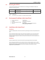
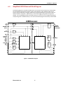
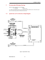
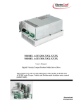
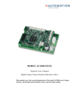
1.1 ACE500 Controller Overview Software This manual describes the installation and operation of the ACE500 series of digital high voltage servo‐amplifiers manufactured by ElectroCraft MI, Inc. This document applies to serial numbers ending with xxxx 0109 and beyond. The ACE500 amplifier is: • Configurable operation modes: Torque, Velocity, and Position. • Selectable BLAC (sine wave, flux vector) or BLDC (Six step, trapezoidal) commutation. • 4 Quadrant performance. • Phase output, PWM controlled output. • Full digital control of all loops • Variable servo rate from up to 10 kHz. • Loop tuning via serial interface (No potentiometers!). • Drive setup & status information available serially via RS232 link. • 90 – 254 VAC input power supply range. • Output current of 7.5 Amp continuous, 15 Amp peak. • Compact package size. • ElectroCraft CompletePower™ Plus graphical windows interface for Setup, Configuration and Tuning. For further documentation support of software and its usage, refer to the ElectroCraft CompletePower™ Plus software user’s manual. Parameters and Variables For further documentation support of parameters, variables, commands and graphing refer to the ElectroCraft Parameter Guide. ElectroCraft, Inc.
5