1
2.3
Board connectivity
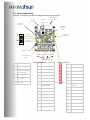
First step in configuring your board is getting familiar with its connectivity.
Balanced Input
Connectors
MiniUSB
DC Input
connection
IN 1
Expansion
connector #1
IN 2
Sensitivity
jumpers for
inputs
S
Jumper in
Slave position
M
Jumper in
Master position
Expansion
connector #2
Master/Slave
jumper
Reset Button
OUT1
OUT2 OUT3 OUT4
Volume control
Header
Output RCA connectors
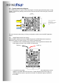
Expansion Connector #1
Pin
Description
Pin
Description
1–4
Ground
1
Analog out #4
5 20
Reserved Pin
Could cause damage
if used improperly
3
Analog out #2
5
Ground
7
Ground
22 / 24
Ground
25 / 27
External DC input
12 ~ 18VDC
9
MCLKIN
26 – 28
Reserved Pin
Do not use
11
I2S_DATA_IN3&4
13
I2S_DATA_IN7&8
15
I2S_IN_BCLK
17
I2S_DATA_OUT3&4
19
IS2_DATA_OUT7&8
21
I2S_OUT_BCLK
23
GND
25
GND
27
Analog In #1
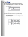
Expansion Connector #2
PIN2
PIN1
Pin
Description
2
Analog out #3
4
Analog out #1
6
Ground
8
Ground
10
I2S_DATA_IN1&2
12
Potentiometer input
10k-100kΩ
14
I2S_IN_LRCLK
16
I2S_DATA_OUT1&2
18
I2S_DATA_OUT5&6
20
I2S_OUT_LRCLK
22
3.3V
24
3.3V
26
GND
28
Analog In #2