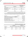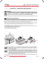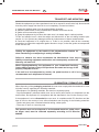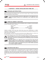
1
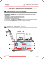
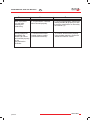
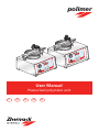
polimer
User Manual
Pressurised polymizer unit
IT
FR
DE
EN
ES
MAINTENANCE AND USE MANUAL
EN
GENERAL INDEX
CH. 1
INTRODUCTION
Pag. 123
Pag. 124
1.1
1.2
How to read and use the manual
Terminology and symbols
GENERAL INFORMATIONS
Pag.
Pag.
Pag.
Pag.
125
125
125
126
2.1
2.2
2.3
2.4
DESCRIPTION OF THE EQUIPMENT
Pag.
Pag.
Pag.
Pag.
Pag.
Pag.
Pag.
Pag.
Pag.
Pag.
Pag.
128
128
129
129
129
130
130
130
131
131
131
3.1
3.2
3.2.1
3.3
3.3.1
3.4
3.4.1
3.5
3.6
3.7
3.7.1
132
132
133
133
4.1
4.1.1
4.1.2
4.1.3
134
134
135
135
5.1
5.2
5.3
5.4
polimer
136
136
136
137
138
138
141
6.1
6.2
6.3
6.3.1
6.4
6.5
6.6
CH. 5
Warning
Packing and unpacking
Transport and mounting
Elimination / Dismantling
INSTALLATION AND FIRST-TIME USE
Pag.
Pag.
Pag.
Pag.
Pag.
Pag.
Pag.
CH. 4
Technical characteristics and operating start
Technical Data
Standard accessories and accessories available on request
Weight and overall dimensions
TRANSPORT AND MOUNTING
Pag.
Pag.
Pag.
Pag.
CH. 3
General description of the equipment
Table of the components - Front view
Description of the components - Front view
Table of the components - Rear view
Description of the components - Rear view
Control panel
Description of control panel components
Data entry
Work times
Identification data
On-equipment labels and symbols
TECHNICAL CHARACTERISTICS
Pag.
Pag.
Pag.
Pag.
CH. 2
Responsibility
Warranty: general instruction
Authorized personnel
General safety regulations
CH. 6
Warnings and precautions
Permitted ambient conditions
Required work space
Worktops
Connecting up to the power supply
Starting up the equipment
Purpose of the equipment / Improper and forbidden use
121 of 200
EN
MAINTENANCE AND USE MANUAL
USING THE EQUIPMENT
Pag.
Pag.
Pag.
Pag.
Pag.
Pag.
Pag.
Pag.
Pag.
Pag.
Pag.
Pag.
Pag.
Pag.
Pag.
Pag.
Pag.
Pag.
142
142
143
144
144
145
145
145
145
146
146
146
147
147
148
148
148
149
7.1
7.2
7.3
7.4
7.5
7.5.1
7.5.2
7.6
7.7
7.8
7.9
7.10
7.11
7.12
7.13
7.14
7.15
7.16
CH. 8
MAINTENANCE
Pag.
Pag.
Pag.
Pag.
Pag.
150
150
151
151
151
8.1
8.2
8.3
8.4
8.5
Cleaning
Routine maintenance
Unscheduled maintenance
Restarting after a long period of inactivity
Requesting technical assistance
CH. 9
TROUBLESHOOTING
Pag. 152
Pag. 152
CH. 7
Warning
Safety system
Data programming
Selecting the default program
Selecting the work cycle
Setting CYCLE 1 and CYCLE 2
Setting CYCLE 3 and CYCLE 4
Heat-treating the crucibles
Saturated steam treatment
Pressurisation of plaster models and fusion linings
Pressurised hygroscopic treatment of cylinders for fusion
Operation: general notes
Correcting data on a program that is running
Changing the program in progress
Checks during work
Acoustic signals
No electrical power
Residual risk
9.1
9.2
Warning
Problems, causes and remedies
A.1
A.2
A.3
A.4
A.5
CE Declaration of conformity
Warranty certificate and identification form
Maintenance and repair worksheet
Authorized service partners
Notes
APPENDICES
Pag.
Pag.
Pag.
Pag.
Pag.
155
156
157
158
158
The data given in this manual may be modified without prior notice.
122 of 200
polimer
MAINTENANCE AND USE MANUAL
EN
CHAPTER 1: INTRODUCTION
HOW TO READ AND USE THE MANUAL
1.1
This Use and Maintenance Manual provides information on the utilisation, installation and
maintenance of the POLYMER Series polymerization unit (versions POLIMER 86,
POLIMER 180), manufactured by Zhermack S.p.A.
• The equipment must be used in accordance with the instructions in this manual: it is therefore
recommended that you read it carefully prior to installation and start-up. Make sure that you
read the entire manual and pay particular attention to messages written in bold type or items
highlighted by boxes and/or symbols: the symbols are designed to highlight situations involving
danger or requiring caution (see paragraph 1.2).
• Observance of standards and regulations shown in this manual will ensure that the equipment
is used properly and that maintenance work is carried out safely.
• This Use and Maintenance Manual is an integral part of the equipment: it should therefore be
kept together with the equipment so that it can be consulted as and when necessary (keep the
booklet in a secure dry place away from sunlight, atmospheric agents, etc.). It must be
available for consultation throughout the working life of the equipment even when the equipment
is sold or finally dismantled.
• It is recommended that you keep this manual constantly updated by integrating any
amendments, additions or modifications made by the Manufacturer. Any notes or comments
should be made on the blank pages at the rear of the booklet (see Appendices: Notes).
• Use the manual properly so that it is not damaged in any way.
• Do not remove, tear or write on any part of the pages.
• If the manual is lost or damaged and its contents become illegible you can request a
replacement copy from the Manufacturer.
The purpose of this Use and Maintenance Manual is to provide users with information on how
to operate the equipment properly. The manual contains all the information needed to use the
device as intended: in particular the manual includes instructions and information on the
following:
• correct installation of the equipment;
• Detailed description of how the equipment works and its components;
• Initial start-up;
• Scheduled maintenance;
• Basic Safety and Accident Prevention info.
This manual contains nine chapters each of which covers a specific argument.
The appendices at the rear of the manual are a useful complement to these chapters.
polimer
123 of 200
EN
1.2
MAINTENANCE AND USE MANUAL
TERMINOLOGY AND SYMBOLS
It is important that you understand the following symbols and their significance as they
highlight important information such as critical situations, practical advice, or straightforward
information.
If you have any doubts as to the significance of a symbol always consult this page.
• Tasks for which failure to observe instructions or tampering with equipment parts may put
personnel in serious danger are highlighted by the symbol:
DANGER!
This symbol refers to safety standards which must be observed at all times in order to
protect both workers and equipment.
• Critical situations concerning dangerous areas or tasks in which failure to observe the
instructions may render the warranty null and void, or cause damage to equipment, connected
components or the surrounding area, are highlighted by the symbol:
WARNING!
This symbol refers to safety standards which must be observed carefully in order to
guarantee your safety, other people's safety and prevent damage to the equipment.
• Any work that fails to comply with instructions in this manual, or any tampering which might
automatically render the warranty null and void, is highlighted by the following symbol:
FORBIDDEN!
This symbol refers to actions which must never be carried out (i.e. forbidden
actions).
• Any general information and/or advice which may be useful at any time is highlighted by the
following symbol:
NOTE!
This symbol highlights information and/or useful advice.
124 of 200
polimer
MAINTENANCE AND USE MANUAL
EN
CHAPTER 2: GENERAL INFORMATIONS
RESPONSABILITY
2.1
Failure to observe the instructions in this Use and Maintenance Manual exonerates the
Manufacturer from any liability whatsoever.
For any matters not covered by this manual or about which you have any doubts please contact
the Manufacturer directly:
Zhermack S.p.A.
Via Bovazecchino, 100
45021 Badia Polesine • RO • Italy
Tel. +39 0425 597 611 • Fax +39 0425 53 596
http://www.zhermack.com
e-mail: [email protected]
If equipment maintenance work fails to comply with instructions or is done in such a way as to
compromise equipment integrity or modify its characteristics Zhermack S.p.A. shall be
exonerated from any liability as regards worker safety and/or equipment performance.
WARRANTY: GENERAL INSTRUCTION
2.2
Included in the Appendices to this Use and Maintenance Manual you will find the Warranty
certificate and the ID Form which must be filled out in full.
In general the Warranty is rendered null and void by the following:
• Improper equipment use.
• Incorrect installation.
• Serious negligence of maintenance schedules.
• Modifications to or work on the equipment which has not been authorised by the Manufacturer
(especially on safety devices).
• Use of non-original spare parts.
Zhermack S.p.A. cannot, as of this moment, be held liable if the equipment is
modified or tampered with without prior written consent from the Manufacturer.
Consequently, any repairs made by unauthorised personnel, use of
non-original spare parts or failure to comply with the installation standards
specified in this manual shall immediately render the Warranty null and void.
AUTHORIZED PERSONNEL
2.3
Personnel may be divided into the following categories:
• Operator-user:
Person trained to use the equipments. He/she may carry out all the tasks needed to
operate the equipments: these tasks include starting/stopping the equipment, carrying out routine
inspections and any other tasks linked to everyday equipment use.
polimer
125 of 200
EN
MAINTENANCE AND USE MANUAL
The operator-user must only use the equipment when it is fully assembled and
the safety devices are working properly as described in this manual.
Before using this equipment or carrying out any work on it, the operator must
read the entire contents of this manual. This manual has been drawn up to
provide the user with essential information on rational, safe utilisation of the
equipment. The user must comply with the information given at all times.
Furthermore, the user must use the work sheets enclosed with this manual so
as to keep a record of maintenance/component replacement work as well as
make notes on any equipment malfunctions.
• Zhermack S.p.A. authorised maintenance technician:
Person authorised to carry out work on the equipment under all operating conditions and all
safety levels. He/she is also authorised to carry out any mechanical or electrical
repairs/adjustments, scheduled maintenance and any component replacement work.
2.4
GENERAL SAFETY REGULATIONS
The operator must read the advice and warnings given below and comply with such regulations
at all times: doing so will ensure safe, long-lasting equipment performance.
• The equipment must only be used at the rated voltage indicated on the oven ID plate.
• Do not allow untrained personnel to use this equipment.
• The equipment is not supplied with gloves or protective glasses; however, the operator must
be in possession of these items in order to utilise the equipment.
• The crucibles must be inserted/removed from the heating chamber with suitable tongs.
• To prevent burns, the lid must only be opened by way of the knob made of insulating material.
• Make sure that the polymerization unit chamber lid is closed before acting on the main
switch.
• The equipment must be positioned on non-flammable supports and tops only; no highly
flammable materials, whether solid, liquid or gaseous, may be stored or used in the vicinity of
the equipment.
• Boiling water and high temperature steam inside the polymerization unit chamber are a potential
source of danger where the equipment is used improperly.
• An info plate reading “WARNING: HOT PARTS” must be placed by the equipment (see section
3.6.1).
• Where the equipment is used as a pressuriser the minimum working temperature MUST be
10°C.
• Take measures to ensure that you are not distracted when using the equipment.
• Never use a malfunctioning equipment and always inform the Maintenance Manager of any
faults.
• It is advisable to use distilled water as the heating liquid, NOT glycerine.
• Before starting the work cycle make sure that the level of distilled water is appropriate for the
work being carried out.
126 of 200
polimer
MAINTENANCE AND USE MANUAL
EN
• It is forbidden to use the polymerization unit without using distilled water.
• Do not leave the equipment unattended with the guards disassembled.
• Do not open compartments containing electrical parts.
• Have the equipment inspected by the Manufacturer and/or Authorised Dealer at least one
every 12 months.
• Do not replace the power lead or tamper with the supplied plug.
• It is forbidden to use the equipment on items other than those for which it has been specifically
designed.
• Before doing any cleaning, routine and/or unscheduled maintenance work make sure that the
equipment has been unplugged from the mains socket.
• Make sure that there are no foreign objects inside the work area as these could damage the
equipment and/or injure personnel.
• Do not use petrol or flammable solvents as detergents; use only non-flammable, non-corrosive,
and non-toxic substances (see paragraph 8 .1).
• Do not used compressed air to clean small pieces; if you do so you should protect your eyes
with goggles that provide lateral protection and limit air pressure to a maximum of 2 bar.
Zhermack S.p.A. cannot be held liable for any damage to persons or objects
caused by incorrect maintenance carried out by unqualified personnel or
maintenance work that does not comply with the instructions in this manual.
Zhermack S.p.A. is, as of this moment, exonerated from any liability concerning
injury to persons or damage to objects that may result from using this
equipment in a way other than that described in this manual.
This equipment has electrical parts: therefore, in the event of a fire, no matter
how small, use only powder-type extinguishers. Never attempt to put out an
electrical fire with water.
polimer
127 of 200
EN
MAINTENANCE AND USE MANUAL
CHAPTER 3: DESCRIPTION OF THE EQUIPMENT
GENERAL DESCRIPTION OF THE EQUIPMENT
3.1
The equipment described in this manual is the POLYMER Series polymerization unit (versions
POLIMER 86 and POLIMER 180). It uses distilled water and has been designed to effect:
• crucible heating.
• pressurisation of plaster models and cylinders for fusion.
• pressurised hygroscopic treatment of cylinders for fusion.
• repairs with self-polymerizing cold resins.
The two versions, POLIMER 86 and POLIMER 180, differ in terms of polymerising chamber
size: the one on the POLIMER 180 is larger and can contain two crucibles.
TABLE OF THE COMPONENTS - Front view
3.2
4
5
6
7
8
1
2
9
10
3
128 of 200
11
polimer
MAINTENANCE AND USE MANUAL
EN
Description of the components - Front view
1.
2.
3.
4.
5.
6.
Polymerization unit chamber lid knob
Pressure gauge
Main ON/OFF switch
Item holder basket
Item holder support
Polymerization chamber
7.
8.
9.
10.
11.
3.2.1
Safety microswitch
Lock handle
Heating LED
Data display
Control panel (see section 3.4)
TABLE OF THE COMPONENTS - Rear view
3.3
12
13
FU
SE
14
16
15
17
Description of the components - Rear view
12. Compressed air connector
13. Pressure regulator
14. Air/water discharge coupling
polimer
3.3.1
15. Pressure vent safety valve
16. Fuse
17. Plug
129 of 200
MAINTENANCE AND USE MANUAL
EN
3.4
CONTROL PANEL
18
22
19
23
20
24
21
25
3.4.1 Description of control panel components
18.
19.
20.
21.
22.
23.
24.
25.
cycle 1 key
cycle 2 key
cycle 3 key
cycle 4 key
PROG. key
“+” key
“-” key
LET. key
3.5
Manual cycle with air release / slow cooling
Manual cycle with air and water release / fast cooling
Automatic cycle with air release / slow cooling
Automatic cycle with air and water release / fast cooling
Access to data programming
Increases data settings
Decreases data settings
Shows the temperature in the polymerization chamber on the display
or time commutation (hours = H; minutes = t)
DATA ENTRY
• Entering temperature data.
Temperature, expressed in degrees Celsius (°C) may vary within the following interval:
minimum ....................... 10°C
maximum .................... 130°C
• Entering data for the polymerization or heating time.
The set time, expressed in hours and minutes is displayed as follows:
“t” ................ time expressed in minutes, variable within an interval of 1-99
“H” .............. time expressed in hours, variable within an interval of 1-99.
Data entry is also possible when the polymerization chamber is open.
130 of 200
polimer
MAINTENANCE AND USE MANUAL
EN
WORK TIMES
3.6
• Polymerization time:
minimum ....................... 1 minute
maximum ….................. 99 hours
• Cold heating time.................... from about 5 minutes to about 7 minutes.
• Hot heating time..................… from about 1 minute to about 3 minutes.
IDENTIFICATION DATA
3.7
The equipment described in this manual has an ID platelet giving information about both the
equipment and the manufacturer:
A
B
D
A.
B.
C.
D.
Zhermack S.p.A.
BADIA POLESINE - ITALY
C305702 - POLIMER 180
Matr. 20000000
230 V~ 50/60 Hz 1600W
Name and address of manufacturer
Equipment code and model
Serial number
Power supply information
C
The equipments has been built in compliance with the EC directives listed in the enclosed "EC
declaration of conformity". When requesting spare parts, information or assistance from your
Authorised Servicing Centre always quote the data on the ID plate.
Should the ID plate deteriorate and become illegible, even partially, order a replacement plate
from the manufacturer: remember to quote the relevant data.
Do not remove and/or damage the plate as you must be able to read the data
at all times.
On-equipment labels and symbols 3.7.1
The following symbols are applied on the equipment:
ATTENZIONE! DANGER OF AN ELECTRICAL
CURRENT. DO NOT OPEN DOORS OR REMOVE PROTECTION BEFORE YOU
HAVE DISCONNECTED THE PLUG FROM THE ELECTRICAL SOURCE.
WARNING! HOT PARTS. EXTREME DANGER.
USE PINCERS, EYE GOGGLES AND HEAT-INSULATED GLOVES.
polimer
131 of 200
EN
MAINTENANCE AND USE MANUAL
CHAPTER 4: TECHNICAL CHARACTERISTICS
4.1
TECHNICAL CHARACTERISTICS AND OPERATING START
Zhermack S.p.A. designs and manufactures work instruments that provide cutting-edge
technology and first-rate quality. They are specially designed to provide made-to-measure
solutions that offer long-lasting performance every single day of their working life.
In making these products Zhermack S.p.A. makes use of the latest design tools, thus ensuring
that all finished equipment is as functional as possible. Use of only top-quality materials and
thorough testing aimed at providing maximum user safety are an Zhermack S.p.A. constant,
making our products safe and internationally competitive.
The POLIMER series polymerization units essentially heat, using distilled waster or saturated
steam, the crucibles and are used for pressurize cylinders.
The POLIMER series polymerization unit with electronic control board and data display screen
has the following features:
• digital controls.
• a 10-program memory with both automatic and manual programs with selectors for final release
of air pressure only or total release of both air and water from the polymerization chamber.
• extremely precise temperature, holding time and working pressure.
• polymerization chamber and load-bearing structure all in stainless style.
• unparalleled adaptability to all resin heat treatment needs.
• safety systems and self-diagnosis system with acoustic warning buzzers and display warnings
to inform the operator of any temperature and/or pressure defects.
• self-locking mechanical safety mechanism.
• pneumatic and water components in brass and stainless steel.
• the polymerisation chamber on the POLIMER 180 version can hold two self-fixing crucibles.
132 of 200
polimer
MAINTENANCE AND USE MANUAL
EN
Technical data 4.1.1
Model:
Interchamber dimensions (cm)
Crucible capacity
Max absorbed power (watt)
Power supply
Pressure range (bar)
Protection rating IP
Noise level
POLIMER 86
12,5Ø x 11(h)
1
1000
230V~ ±10% 50/60Hz
6
IPX0
<70 dB
POLIMER 180
18Ø x c14(h)
2
1600
230V~ ±10% 50/60Hz
6
IPX0
<70 dB
Standard accessories and accessories available on request 4.1.2
In addition to this Use and Maintenance Handbook the equipment comes complete with:
COMPONENTS
QUANTITY
STAINLESS STEEL holed chamber basket for POLIMER 86
1
STAINLESS STEEL holed chamber basket for POLIMER 180
1
Item holder support for POLIMER 86
1
Item holder support for POLIMER 180
1
Toothed tongs for basket
4
Brass self-fixing crucible (on request)**
Plastic container for air/water collection (5 litres)
1
Compressed air connection hose (metres)
2
ORD. CODE*
XD0070150
XD0070200
XR0070090
XR0070095
XI0070030
C308000
XI0070040
XF0486320
* Please quote the order code when ordering a spare part. You may order parts from your local Authorised Servicing Centre.
** The self-fixing crucible is completely made of brass and fitted with stainless steel screws for a hermetically sealed closure.
Weight and overall dimensions 4.1.3
POLIMER 86
DIMENSIONS
WITHOUT PACKING
Height (h)
Length (l)
Depth (p)
Weight
cm 27
cm 36
cm 32
kg 17.5
polimer
WITH PACKING
cm 53
cm 39
cm 55
kg 20.5
POLIMER 180
WITHOUT PACKING WITH PACKING
cm 30
cm 41
cm 38
kg 25
cm 55
cm 57
cm 58
kg 29.5
133 of 200
EN
MAINTENANCE AND USE MANUAL
CHAPTER 5: TRANSPORT AND MOUNTING
5.1
WARNING
To prevent any injury to persons or damage to things always proceed with the
utmost care and attention when handling the equipment. Observe all the
precautions and instructions contained in the following paragraphs.
5.2
PACKING AND UNPACKING
All the material is thoroughly checked by the Manufacturer prior to shipment. When you
receive the goods make sure they have not been damaged during transit and that no-one has
tampered with the packaging and removed any of the parts contained therein.
Should you note any damage or missing parts please inform your Dealer and the shipping
carrier immediately: take photographs and send them on to both dealer and carrier.
The packaging, consisting of a cardboard box with internal expanded plastic padding, contains:
• the POLIMER series polymerization units;
• standard equipment (see section 4.1.2);
• this Use and Maintenance Manual.
The equipment is not supplied with pincers, gloves or protective glasses;
however, the operator must be in possession of these items in order to
utilise the equipment.
It is recommended that you keep the original packaging so that, if
necessary, it can be re-utilised; doing so ensures that you do not use
unsuitable packaging materials during transport and handling which might
lead to accidental damage (see section 5.3).
134 of 200
polimer
MAINTENANCE AND USE MANUAL
EN
TRANSPORT AND MOUNTING
5.3
Should the equipment you have purchased need to be moved it must first be fully disconnected
from the power supply and then left to cool completely. Proceed as follows:
1. empty the distilled water from the polymerization chamber;
2. place the basket back in the polymerization chamber and close the lid;
3. gather all its accessories together;
4. grasp the equipment by its base and make sure it is always kept in vertical position.
To this end always bear in mind the weight and dimensions of the unit being handled (see
section 4.1.3) to prevent any damage caused by inobservance of these measurements.
5. Pack the equipment in its original box or, if this is not possible, take all the necessary
precautions to protect the equipment against knocks or drops, in that the goods are transported
at the owner's risk.
Holding the equipment by the handle of the polymerization chamber lid
when transferring or transporting is strictly forbidden.
Failure to observe the above exonerates the Manufacturer from any
liability concerning equipment malfunction and consequently renders the
Warranty null and void.
When shipping/delivering the equipment to your Authorised Servicing
Centre always enclose a copy of the purchase document and a copy of the
properly compiled ID form.
If the unit is to be transported by courier, the postal service or rail it is
recommended such shipments be insured.
ELIMINATION / DISMANTLING
5.4
When disposing of the packaging materials the user must comply with the standards in force
in his/her country regarding the following materials:
• Wood/paper: non-polluting materials, but must be recycled properly.
• Polystyrene/plastic: pollutants which must not be burnt (toxic fumes) nor dispersed into the
environment, but disposed of in compliance with the standards in force in the country of use.
If the equipment is to be dismantled the user must, in compliance with EC directives and the
laws in force in the country of use, effect elimination and recycling of the following materials:
• Plastic and glass parts, insulated electrical wiring, rubber parts.
• There are no toxic or corrosive parts.
This product must not be disposed of as household waste but rather, when
no longer used, must be collected separately according to EC Directive
2002/96.
polimer
135 of 200
EN
MAINTENANCE AND USE MANUAL
CHAPTER 6: INSTALLATION AND FIRST-TIME USE
6.1
WARNINGS AND PRECAUTIONS
Before proceeding with installation make sure that all relevant safety conditions prevail and
follow the instructions below carefully.
So as to provide greater clarity the numbers given in the diagrams in this
chapter correspond exactly to the numbering in the Components Table
(Ch. 3).
6.2
PERMITTED AMBIENT CONDITIONS
Unless stated otherwise at the time of order the equipment will be configured to operate properly
under the following ambient conditions:
Place of Use
Altitude
Working temperature
Humidity
Indoors
Up to 2000 m
From 5°C to 40°C
Max 80%
Ambient conditions other than those listed above may cause malfunctions or sudden
breakdowns. Lighting in the installation area must be sufficient to provide good visibility at every
single point on the equipment.
More specifically, luminosity must not be less than 200 lux, lighting must be as uniform as
possible and there must be no reflected light as this could dazzle the operator.
The equipment must not be used in workplaces having an atmosphere which is
explosive and/or at risk of fire as it has not been designed for use in such areas.
Nevertheless, should a fire accidentally break out follow the procedure described
in paragraph 2.4.
Work area lighting is an important factor in both personnel safety and the
ultimate quality of the work being done. In Italy lighting must comply with a
Ministerial Decree Law that clearly defines minimum lighting requirements. In
other countries lighting requirements form part of the accident prevention
and workplace hygiene standards.
6.3
REQUIRED WORK SPACE
Choosing a good workplace with an appropriate amount of space available for equipment
installation is an essential factor in personnel safety, the quality of the work and proper
maintenance. This zone must not only be spacious enough to allow for optimum equipment
operation but must also be well illuminated, aired, not dusty and not exposed to direct sunlight.
Note also that the unit must be positioned so the connection plug can be handled/manipulated with
ease.
136 of 200
polimer
MAINTENANCE AND USE MANUAL
EN
The equipment must rest on non-flammable supports and tops only.
It is strictly forbidden to store any solid, liquid or gaseous flammable substances
in the vicinity of the equipment.
Worktops 6.3.1
5
The equipment has been designed for use on a rigid worktop parallel to the floor.
Suitable worktops include service furniture (where the operator is standing) or modelling tables
(where work is done sitting down). All worktops must be checked for stability.
polimer
137 of 200
EN
6.4
MAINTENANCE AND USE MANUAL
CONNECTING UP TO THE POWER SUPPLY
The user must provide a power connection with relative socket near the equipment installation
point. The user must also install an adequate electrical circuit breaker upstream from the socket
as well as efficacious overload/indirect contact safety devices.
Connection is effected via the safety plug (16A, in compliance with European standards) at the
end of the power lead: this must be inserted in the mains socket.
When connecting check:
• that mains voltage and frequency are as indicated on the identification plate (incorrect power
supply voltage may damage the equipment);
• that the mains supply has a proper, efficient earth connection.
It is forbidden to tamper with the power lead and its plug. When replacing them
owing to damage and/or wear please contact an Authorised Service Centre.
A proper earth connection is compulsory. Should it temporarily be necessary to
use an extension lead the latter must comply with the standards in force in the
country of use.
If there are fluctuations in power supply voltage or if the equipment is deactivated while it is
working or in any case connected to the mains power supply, proceed as explained in section
7.15.
6.5
STARTING UP THE EQUIPMENT
Fig. 1 : Position the equipment correctly in the
designated area, observing the instructions in
paragraphs 6.3 and 6.3.1.
Connect the lead (17) to the mains
power socket: follow the instructions in
section 6.4 carefully.
Figure
1
12
Figure
17
Fig. 2 : Connect the air line coupling (12) to the
compressor via the special tube.
2
138 of 200
polimer
MAINTENANCE AND USE MANUAL
EN
The compressor must be calibrated to a minimum pressure of 6 bar; if this is
not so act on the pressure switch.
During final testing POLIMER polymerization units are calibrated to a
pressure of 6 bar. If such pressure is not detected the cause can only lie in
compressor adjustment. However, if the latter is regulated appropriately and
pressure is still low the regulator (13) on the polymerization unit can be
adjusted.
Fig. 3 : Connect the air/water discharge (14) to the
hose (x) that connects the supplied air/water
collection container (y).
y
x
14
5
Figure
Fig. 4 : Turn the handle (8) upwards, then rotate it
90° in the direction indicated by the arrow in the inset
diagram; open the polymerization chamber lid using
the knob (1).
1
8
Figure
Fig. 5 : Wearing protective gloves, extract the basket
(4) from the polymerization chamber (6).
Then place the crucible in the basket.
3
4
4
If you need to polymerize wax models, use the item
holder support (5) to fix the components to the
basket.
5
6
Figure
5
The use of protective gloves and tongs is recommended during insertion and
removal of the basket (4), the item holder support (5) and the crucibles.
polimer
139 of 200
EN
4
MAINTENANCE AND USE MANUAL
Fig. 6 : Put the basket (4) back in the polymerization
chamber (6), making sure that the notch on the
basket lines up with the vertical runner on the inner
wall of the polymerization chamber.
6
6
Figure
Fig. 7 : Pour a quantity of the distilled water into the
polymerization chamber (6) that corresponds to the
type of job being carried out, then lower the chamber
lid.
Figure
7
It is recommended distilled water be poured into the polymerization chamber
to a minimum depth of approximately 2 cm and no higher than the maximum
as marked on the internal wall of the chamber itself.
Fig. 8 : Seal the polymerization chamber hermetically
by turning the lock handle (8) 90° clockwise (see
section 7.2).
8
Figure
8
Fig. 9 : Rotate the handle (8) downwards; the safety
microswitch (7) (in the lower part of the equipment) in
contact with the handle ensures secure closure.
8
7
Figure
If the lock handle does not come into
contact with the safety microswitch,
the equipment will not work.
9
140 of 200
polimer
MAINTENANCE AND USE MANUAL
EN
Fig. 10 : Press the main switch (3) positioned on the
display: the switch will light up.
• the word OFF appears on the display (10).
After pressing the main switch, wait
about 10 seconds before starting data
programming.
10
3
Figure
10
Programming data can also be entered with the polymerization chamber lid
open.
Once the work cycle is over the chamber lid must only be opened via the handle
(1), made of insulating material.
Failure to observe any of the above equipment installation instructions may
lead to malfunctions and render the warranty null and void.
PURPOSE OF THE EQUIPMENT / IMPROPER AND FORBIDDEN USE
6.6
POLIMER polymerization units have been designed and built to perform the following:
• crucible heating
• pressurisation of plaster models and cylinders for fusion.
• pressurised hygroscopic treatment of cylinders for fusion.
• repairs with self-polymerizing cold resins.
Using the equipment for any purpose other than that described in this Manual
shall be considered improper and thus forbidden.
The equipment must not be used to fire materials that generate smoke.
Improper use renders the Warranty null and void and Zhermack S.p.A. shall not
be liable for any damages to objects, workers or third parties.
The main reasons for which the Warranty may be rendered null and void are given in section
2.2 and in the "Warranty Certificate" enclosed with this Manual.
polimer
141 of 200
EN
MAINTENANCE AND USE MANUAL
CHAPTER 7: USING THE EQUIPMENT
7.1
WARNINGS
The equipment must not be used with any of its parts disassembled: before
using the equipment make sure that all its components are properly in place.
To ensure that work is done in absolute safety always make sure that you
follow the described procedures with caution.
To provide greater clarity the numbers given in the diagrams in the following
paragraphs correspond exactly to the numbering in Chapter 3 in the
"Equipment Description" section.
7.2
SAFETY SYSTEMS
1. Opening the lid of the polymerization unit trips a microswitch (7) located beneath the lock
handle (8). Pressing this pin automatically discharges pressure.
2.
Polymerization chamber anti-aperture mechanism on lock handle unit (8).
3. The polymerization unit is equipped with a “temperature alarm” system.
If, while the equipment is working, one of the following occurs:
• short circuit on temperature sensor
• temperature sensor connection wire damaged
• temperature rises above 140°C
the display (10) shows the flashing “TEMP” message, the LEDS on all the CYCLE keys (18, 19,
20, 21) flash and an intermittent beep warns the user of the problem.
To reset the polymerization unit just press one of the four CYCLE keys (18, 19, 20, 21).
Contact an Authorised Service Centre before re-using the polymerization unit.
4. Throughout the work cycle, the polymerization unit emits a series of beeps to indicate
transition from one work phase to another.
When these beeps are no longer heard the work cycle is over and the polymerization chamber lid
can be opened “safely”. Remember that the lid must only be opened after first checking, on the
display (10), that temperature has dropped below 95°C and that the pressure gauge (2) reads
zero.
5. During heating (between approximately 60°C and 70°C), the pressure can rise to over 6 bar.
This is normal in that the water heats up and increases the volume of the oxygen and thus increases pressure.
This increase acts on the internal overpressure valve of the polymerization unit which has a
threshold setting of 6.8 bar: when this pressure is reached it opens and releases the excess pressure automatically.
6.
The polymerization unit also has an 8 Amp safety fuse (16).
142 of 200
polimer
MAINTENANCE AND USE MANUAL
EN
To prevent accidents always observe the instructions in this manual. Should
you have any doubts at all please contact the Manufacturer or your Authorised
Servicing Centre.
Equipment safety devices/guards must never be removed except for repair and
maintenance purposes.
Such items must be replaced as soon as the situation which led to their removal
no longer exists and in any case before the equipment is used again.
DATA PROGRAMMING
7.3
1.
The polymerization unit is OFF, as shown on the display (10).
2.
Press PROG. (22):
• “Pro 01” appears on the display (10) to inform the user that data will now be entered for
program 01.
3.
Press PROG. (22) again:
• the “C” symbol appears on the display (10) to indicate temperature in degrees Celsius.
4.
Set the desired temperature by pressing:
• the “+” key (23) to increase the value of the data item on the display (10) or the “-” key
(24) to reduce it.
5.
Press PROG. (22) again:
• the symbols “t” and “H”, indicating the time in minutes hours respectively, appear on the
display (10).
To switch from the minute setting to the hour setting press the LET key (25).
The time parameter must be set during data programming.
6.
Set the desired polymerization time by pressing “+” (23) or “-” (24) to increase or decrease
the values shown on the display (10).
7.
Press PROG. (22) again:
• the word OFF appears on the display (10).
At this point all the Program 01 data has been entered.
8.
To insert the data for program 02 proceed as follows:
• press PROG. (22). The legend “Pro 01” appears on the display (10), indicating program
01 in which the data has already been entered.
9.
Press the “+” key (23): “Pro 02” now appears on the display (10), indicating that the user
can now start entering programming data for program 02.
10. Repeat the above procedure as describe din points 3, 4, 5, 6 and 7.
To complete the remaining eight programs proceed as per Program 02.
polimer
143 of 200
EN
MAINTENANCE AND USE MANUAL
To vary the data settings first press the PROG. key (22) to exit programming
mode and return to the initial OFF conditions. Then run through the above
procedure.
Data programming can be carried out with the polymerization chamber open
or closed.
When the polymerization unit is switched on the display (10) always shows
the last program used.
7.4
SELECTING THE DEFAULT PROGRAM
1. When the display (10) reads OFF press PROG. (22); the display shows the last program
used.
2. Act on the “+” (23) and “-” (24) keys to select the desired program on the display (10),
already used and thus already set.
3. Press PROG. (22) and the display (10) shows the set time.
4. Press PROG. (22) again and the display (10) shows the set time.
5. Press PROG. (22) again and the display (10) reads OFF.
7.5
SELECTING THE WORK CYCLE
The user can choose one of four different work cycles:
• CYCLE 1, key (18):
“Manual” cycle with pressure regulation and release of air only at end of cycle.
The hot water stays in the polymerization chamber and cooling takes place slowly.
• CYCLE 2, key (19):
“Manual” cycle with pressure regulation and release of both air and water at end of cycle.
The polymerization chamber is emptied of water completely and cools quickly.
• CYCLE 3, key (20):
“Automatic” cycle with immediate attainment of a pressure of 6 bar and release of air only
at end of cycle. The hot water stays in the polymerization chamber and cooling takes place
slowly.
• CYCLE 4, key (21):
“Automatic” cycle with immediate attainment of a pressure of 6 bar and release of both air
and water at end of cycle. The polymerization chamber is emptied of water completely and
cools quickly.
144 of 200
polimer
MAINTENANCE AND USE MANUAL
EN
Setting CYCLE 1 and CYCLE 2 7.5.1
1.
Press the “+” key (23) to set the desired pressure in the polymerization chamber (from a
minimum of 0 to a maximum of 6 bar).
The pressure value can be read off on the gauge (2).
If the pressure setting is higher than desired, rotate the handle (8) as you would to open
the polymerization chamber: this causes the immediate interruption and reset of the
selected cycle and vents the pressure.
Re-close the polymerization chamber.
2.
Press CYCLE 1 (18) or CYCLE 2 (19).
Setting CYCLE 3 and CYCLE 4 7.5.2
If CYCLE 3 (20) or CYCLE 4 (21) is selected the user, after closing the polymerization
chamber and entering the program data (see section 7.3) just needs to press key (20) or key
(21).
HEAT-TREATING THE CRUCIBLES
7.6
1.
Place the crucible in the basket and place the entire set in the polymerization chamber,
making sure that the notch on the basket lines up with the vertical runner on the inner wall
of the polymerization chamber (section 6.5).
2.
Pour distilled water into the polymerization chamber until it covers the crucible itself but
never exceed the maximum level as marked on the inner wall of the chamber (section 6.5).
3.
Set the temperature (section 7.3).
4.
Set the heating time (section 7.3).
5.
Lower the lid of the polymerization chamber with the aid of the knob (1) and secure it with
the lock handle (8).
6.
Now select the desired work cycle (section 7.5).
SATURATED STEAM TREATMENT
7.7
For saturated steam heating the procedure is as per section 7.6 except for point 2: the distilled
water poured into the polymerisation chamber must cover the surface on which the crucible
basket rests by only a little, but must in any case reach a depth of at least 2 cm.
polimer
145 of 200
EN
7.8
MAINTENANCE AND USE MANUAL
PRESSURISATION OF PLASTER MODELS AND FUSION LININGS
1.
Carry out the tasks described in points 1, 2 and 3, section 7.3.
2.
Set the temperature to 10°C (section 7.3).
3.
Set the desired pressurisation time (section 7.3).
4.
Set the desired work cycle (see section 7.5).
7.9
PRESSURISED HYGROSCOPIC TREATMENT OF CYLINDERS FOR FUSION
1.
Carry out the tasks described in points 1, 2, and 3 of section 7.3.
2.
Pour a quantity of distilled water into the chamber sufficient to cover the number of
cylinders inserted in the basket.
3.
Set the temperature to 37°C (section 7.3).
4.
Set the time necessary for the hardening of the lining being used (section 7.3.).
5.
Choose one of the manual cycles: CYCLE 1 (18) or CYCLE 2 (19) and set a polymerization
chamber pressure of 4 bar (see section 7.3.2).
7.10
OPERATION: GENERAL NOTES
After setting the data as explained in section 7.3 and choosing the work cycle (see section 7.5)
the following occurs:
1.
The green LED in the selected work cycle key flashes.
2.
The temperature increase is shown on the display (10).
3.
When the set temperature is reached, the following occurs:
- the set cycle LED stops flashing but stays on.
- a low frequency beep lasting 30 seconds is emitted.
- the set heating or pressurisation time begins.
- the set heating time appears on the display (10) and begins counting down when heating
begins so that the user can see how much time is left before the end of heating.
If the set time is expressed in hours the countdown will initially decrease by
the minute and then the hour: the display (10) show hours and minutes. If
less than one hour remains the countdown is in seconds and the display (10)
shows the remaining minutes and seconds.
If the set time is expressed on the display (10) in minutes only the
countdown will be by the second, with the remaining minutes and seconds
being displayed.
146 of 200
polimer
MAINTENANCE AND USE MANUAL
4.
EN
During heating the yellow HEATING LED (9) lights up when the power regulator comes on
to maintain polymerization chamber temperature.
The user can check the in-chamber temperature at any time during the
heating phase by pressing the LET key (25); after a few seconds the display
(10) reverts to countdown mode.
5.
At the end of firing the following occurs:
- the temperature in the polymerization chamber appears on the display (10).
- air or air/water discharge takes place depending on the selected work cycle.
- an intermittent acoustic warning sounds and persists until the temperature drops to 95°C.
The intermittent warning beeper stays on until temperature drops below
95°C. When it stops the operator can then open the polymerization chamber
lid safely.
If the temperature setting is less than 95°C the signal will last just 10 seconds to indicate the end of the work cycle.
Before opening the polymerization chamber lid always check the display
(10) to make sure that the temperature has dropped below 95°C and that the
pressure gauge (2) indicates zero pressure.
CORRECTING DATA ON A PROGRAM THAT IS RUNNING 7.11
Settings can also be modified when work is in progress: proceed as follows:
1.
Press twice, in rapid succession, the key relative to the cycle in progress.
Doing this may result in a slight loss of pressure, visible on the gauge (2).
The water, however, remains in the polymerization chamber.
2.
The word OFF appears on the display (10).
3.
Correct the setting (see section 7.3).
4.
Restart the interrupted cycle, restoring, if necessary, in “Manual” cycles, the pressure lost
as described in point 1 (see section 7.5.1).
CHANGING THE PROGRAM IN PROGRESS 7.12
If an incorrect cycle key is pressed by accident proceed as described in section 7.11, except for
point 3.
polimer
147 of 200
EN
7.13
MAINTENANCE AND USE MANUAL
CHECKS DURING WORK
Checking data settings.
The user can check settings at any time when the selected cycle is in progress by
proceeding as follows:
- press PROG. (22): the temperature setting appears on the display (10).
- press PROG. (22) again: the set heating time appears on the display (10).
After a few seconds the display (10) reverts to its pre-check status.
Checking the temperature in the chamber during heating.
Press the LET key (25): for a few seconds the display (10) shows the temperature in the
chamber and then reverts to countdown mode.
Checking the temperature in the chamber with the machine off.
- Press the main switch (3), the key LED comes on.
- the word OFF appears on the display (10).
- press the LET key (25).
- for a few seconds the display (10) shows the temperature in the chamber and then the
word OFF reappears on the display (10).
7.14
ACOUSTIC SIGNALS
The POLIMER series polymerization unit emits a series of beeps to indicate the various phases
of the work cycle:
• A long, intermittent sound indicates that the set temperature has been reached and the
simultaneous start of the polymerization (or heating) phase.
• Once the polymerization time has expired and after the release of the air or air/water a
brief intermittent sound indicates the start of cooling. The cessation of this sound indicates
that the polymerisation chamber lid can now be opened “safely”.
• The polymerization unit also emits a sound in the event of a malfunction (see section 7.2).
7.15
NO ELECTRICAL POWER
While the equipment is coming up to temperature.
If there is a mains power failure during the preheating phase, the following occurs when the
power is restored:
- the word OFF appears on the display (10).
- the green LEDs on the four CYCLE 1 (18), CYCLE 2 (19), CYCLE 3 (20) and CYCLE 4
(21) keys come on.
- restart the interrupted cycle by pressing the corresponding key.
148 of 200
polimer
MAINTENANCE AND USE MANUAL
EN
During actual heat treatment or polymerisation.
1. If the set temperature is below 95°C, interruption of the electrical power supply during
heat treatment resets the cycle; when the power is restored the following occurs:
- the word OFF appears on the display (10).
- the green LEDs on the four CYCLE 1 (18), CYCLE 2 (19), CYCLE 3 (20) and CYCLE 4
(21) keys come on.
- the yellow LED on the PROG. key (22) comes on.
- the pressure remains unaltered and the distilled water is not discharged.
- restart the interrupted cycle by pressing the relative key.
2. If the set temperature is above 95°C, when the power is restored the following occurs:
- the temperature in the polymerisation chamber at that moment appears on the display
(10).
- the green LEDs on the four CYCLE 1 (18), CYCLE 2 (19), CYCLE 3 (20) and CYCLE 4
(21) keys flash to indicate the anomaly.
- the fast frequency warning signal is sounded.
- the pressure in the chamber is released while the water remains in the polymerisation
chamber.
If the operator is not in the laboratory the acoustic warning ceases when temperature drops
below 95°C and the green LEDs continue flashing.
To restart the interrupted cycle proceed as follows:
- press the desired cycle key.
- the word OFF appears on the display (10).
- start the desired cycle by pressing the cycle key again.
3. If you wish to remove the work item from the polymerization chamber at the time of the
power failure proceed as follows:
- act on the safety valve (15) at the back of the polymerization unit and leave it open a few
minutes until all the air has been discharged.
- open the polymerization unit lid.
RESIDUAL RISK 7.16
Residual risk is:
• a danger that cannot be completely eliminated through design and application of safety devices.
• a potential danger which cannot be highlighted.
The POLIMER reach very high temperatures and thus allow specific odontotechny materials to be
fired; the residual risks thus consist of:
• accidental contact (and/or caused by a safety system fault) with the materials or the equipment
itself, during and after the melting phase (risk of serious burns to limbs).
• work carried out on the equipment interior by unauthorised personnel.
The POLIMER is a equipment that could potentially cause an explosion or fire
where users fails to observe the instructions given in this manual.
Should you have any doubts or queries please do not hesitate to get in touch
with the Manufacturer or an Authorised Servicing Centre.
The above-mentioned dangers are indicated by special labels attached to the equipment, as
described in sub-section 3.7.1.
polimer
149 of 200
EN
MAINTENANCE AND USE MANUAL
CHAPTER 8: MAINTENANCE
8.1
CLEANING
The equipment exterior can normally be kept clean just by wiping it with a dry cloth. If necessary,
wet the cloth just a little water or use a non-degreasing detergent.
The operator must ensure that the equipment is kept clean and free from any foreign bodies
such as dirt, water, non-conducting liquids etc.
The equipment must be cleaned at the end of every work session to remove all residues.
Cleaning must be done with the equipment at standstill and positioned in a stable manner.
To clean the inside of the polymerization chamber proceed as follows:
prepare a 50/50 water-vinegar mix, pour it into the polymerization chamber and leave it there
for about 30 minutes at a temperature of about 80°C.
Before cleaning the equipment exterior always turn the main switch to OFF. It is
strictly forbidden to clean the equipment while it is connected to the mains
power supply.
Never use inflammable, corrosive, alkaline or toxic liquids when cleaning the
equipment.
Eye goggles and a face mask must be worn when using compressed air for
cleaning purposes. Do not allow any persons near the equipment as they could
be hit by flying dust.
8.2
ROUTINE MAINTENANCE
Once the equipment has been cleaned (see section 8.1) the operator must check for worn,
damaged or loose parts. If any such anomalies are discovered contact your Authorised
Servicing Centre.
Should any of the above anomalies be discovered it is strictly forbidden to
restart the equipment before such faults have been set right.
More precisely, should the operator note any defects or problems of any kind whatsoever he/she
must place a warning sign on the equipment indicating that maintenance work is in progress and
that using the equipment is forbidden (EC-compliant signs can be purchased from the relevant
suppliers).
Routine maintenance, cleaning and proper equipment use are essential factors in guaranteeing
long-lasting equipment performance and safety.
Never use a naked flame to see what you are doing during checks or maintenance
operations.
150 of 200
polimer
MAINTENANCE AND USE MANUAL
EN
Equipment safety devices/guards must never be removed except for repair and
maintenance purposes.
Such items must be replaced as soon as the situation which led to their removal
no longer exists and in any case before the equipment is used again.
UNSCHEDULED MAINTENANCE
8.3
Unscheduled maintenance (to be carried out by qualified, authorised personnel only) includes
repairs of accidental breakages and replacement of worn or faulty parts.
All electrical and mechanical work must only be carried out by an authorised
Zhermack S.p.A. maintenance technician.
Modifications which alter the equipment characteristics from a safety and
risk prevention viewpoint may only be made by the Manufacturer who shall
then issue a certificate stating that the equipment conforms to safety standards.
Therefore any modification or maintenance tasks not actually described in
this manual are to be considered forbidden. If the equipment is modified,
tampered with or repaired by unauthorised personnel or non-original spare
parts are used the manufacturer is relieved of all responsibility. If a maintenance
task is required but is not described in this manual you must contact an
Authorised Servicing Centre.
RESTARTING AFTER A LONG PERIOD OF INACTIVITY
8.4
Should the equipment be used after remaining idle for a long period proceed as described in
Chap. 6 (start-up) and, if necessary, re-enter the data as described in Chap. 7.
If there are any faults or malfunctions proceed as described in Chapter 9 (Troubleshooting). If the
problem persists or is not covered by the information in this chapter contact your Authorised
Servicing Centre immediately.
REQUESTING TECHNICAL ASSISTANCE
8.5
To obtain technical assistance choose one of the following options:
1. contact your Authorised Servicing Centre.
2. telephone the Zhermack S.p.A. Customer Assistance Service on the number
+39 0425.597.611 and proceed as follows: give personal data (e.g. address and telephone n.),
state the information on the equipment ID plate (see paragraph 3.3) and explain the
problem clearly.
3. fax all the above information and a properly filled out ID Form (see Appendix 2) to
+39 0425.53.596.
polimer
151 of 200
EN
MAINTENANCE AND USE MANUAL
CAPITOLO 9: TROUBLESHOOTING
9.1
WARNING
Should any of the anomalies described below occur try setting the situation
right, as far as is permissible, by following the instructions contained in this
handbook. Should the problem persist contact your Authorised Servicing
Centre.
9.2
PROBLEMS, CAUSES AND REMEDIES
PROBLEM
After powering the
equipment via the
main switch the
on-key LED fails to
come on.
CAUSE
1. Plug is not connected to
the mains socket.
Power lead is damaged.
2. Fuse blown.
REMEDY
1. Connect the plug to the mains
socket properly.
Have the power lead replaced by
an Authorised Servicing Centre
only.
2. Change the fuse, using one of
identical characteristics (T 10 A).
Contact an Authorised Servicing
Centre only.
No pressure.
1. Compressor or
polymerization unit adjusted
incorrectly.
1. Act on compressor pressure
switch or the polymerisation unit
pressure regulator (13).
“TEMP” flashes on
the display (10),
CYCLE LEDs flash
and fast frequency
warning sounds.
1. The “temperature alarm”
system has tripped (see
point 3, section 7.2).
1. Press one of the four CYCLE
(18, 19, 20, 21) keys to reset the
polymerization unit and contact an
Authorised Service Centre.
Sudden interruption
and reset of
selected work cycle
and pressure
release.
1. Accidental opening of
polymerization chamber lid.
1. Re-close the polymerization
chamber lid and reset the data.
Pressure escapes
during routine
operation.
1. Activation of overpressure
valve inside the
polymerization unit because
pressure has increased
beyond set value.
1. Situation part of normal operation
(see point 5, section 7.2).
152 of 200
polimer
MAINTENANCE AND USE MANUAL
PROBLEM
EN
CAUSE
REMEDY
Work cycle does
not start after
pressing the
relative key.
1. Polymerization chamber
lid not closed properly.
1. Close polymerization chamber by
rotating handle (8) properly so that
it presses downwards on the safety
microswitch (7).
During equipment
installation the
basket (4) cannot
be inserted properly
in the
polymerisation
chamber.
1. Sintered filter under
basket support grating
positioned incorrectly.
1. Position sintered filter properly.
If the problem persists, contact an
Authorised Service Centre.
polimer
153 of 200
EN
MAINTENANCE AND USE MANUAL
APPENDICES
CE DECLARATION OF CONFORMITY
A.1
WARRANTY CERTIFICATE AND IDENTIFICATION FORM
A.2
MAINTENANCE AND REPAIR WORKSHEET
A.3
AUTHORIZED SERVICE PARTNERS
A.4
NOTES
A.5
154 of 200
polimer
MAINTENANCE AND USE MANUAL
EN
CE DECLARATION OF CONFORMITY
The Manufacturer:
A.1
Zhermack S.p.A.
Via Bovazecchino, 100
45021 Badia Polesine • RO • Italy
Tel. +39 0425 597 611 • Fax +39 0425 53 596
Declares that the equipment described below:
polimer 86 , polimer 180
Conforms to the legislative dispositions established in the following laws:
· EC Directive 2004/108 EC (EMC Directive) and subsequent amendments.
· EC Directive 2006/95 (Low Voltage Directive) and subsequent amendments.
Please note that manufacturer’s liability for damages caused by a defective product expires 10
years from the date in which the manufacturer put such product on the market and that such
liability is transferred to the user as stated in EC Directive 85/374.
Badia Polesine, 16/01/2007
polimer
Tiziano Busin
Managing Director
155 of 200
EN
A.2
MAINTENANCE AND USE MANUAL
WARRANTY CERTIFICATE AND IDENTIFICATION FORM
1. This document certifies that the Manufacturer has built the product correctly using only top quality materials,
carried out all the necessary tests and that the product complies with EC directives. This product Warranty is valid
for 12-months as from date of delivery to the customer. Proof of such date shall be provided by a purchase document
or the completed identification form. These documents must be handed over together with the equipment to the
Servicing Centre. Persons wishing to make use of warranty coverage must make the fault known within eight days
of its discovery as per Italian civil code art. 1495. Warranty cover is limited to replacement or repair of individual
components or pieces with manufacturing defects and does not cover costs related to transfer of technical
personnel, transport, packing etc. Breakdowns, faults or damages which derive from poor maintenance, incorrect
power supply, negligence, inexperience and other causes not imputable to the Manufacturer and parts subject to
normal wear are not covered by the Warranty. The Warranty does not cover breakdowns caused by failure to carry
out routine maintenance or customer negligence.
This Warranty does not provide for any awards for direct or indirect damages of any kind caused to persons or things
by any equipment inefficiency.
2. The Warranty is instantly rendered null and void if the equipment is repaired, modified or tampered with by the
purchaser or any unauthorised third parties.
Responsibility for damages caused by defective products expires 10 years after the Manufacturer puts them on the
market: after such time damages are the user's responsibility, as stated in EC Directive 85/374.
3. To have work carried out under Warranty the purchaser must only contact the retailer, the Manufacturer-authorised
servicing centres, or the Manufacturer.
The Warranty entitles the purchaser to free replacement of defective parts. It does not entitle the purchaser to
replacement of the entire equipment.
4. In the event of disputes over application of the Warranty, the quality or condition of the equipment, the purchaser
shall not suspend payment or delay payment of the price or price instalment.
5. The purchaser shall not be entitled to damages for any loss of production.
6. The Warranty is rendered null and void if:
a. the equipment is damaged by a fall, exposed to fire, spilt liquids, lightning, natural disaster or any other
cause not imputable to the Manufacturer.
b. installation has not been carried out properly.
c. power supply is incorrect (e.g. rated mains voltage incorrect). Erroneous mains connection (rated mains
voltage incorrect), or failure to install proper protection devices.
d. the serial number has been removed, cancelled out or altered.
7. Any components to be replaced under the terms of the Warranty shall be sent back to Zhermack S.p.A. which
shall then send the appropriate spare parts. Should the changed part not be replaced it shall be charged to the
person who ordered it.
8. The Manufacturer and the Dental Deposit are not required to provide replacement equipments while repairs are
carried out.
9. Spare parts shall, for tax purposes, only be provided under warranty where the relevant limitations set out in the
terms and conditions of the warranty are observed.
10.For any other eventuality not provided for by this Warranty Certificate and the regulations consult the Italian Civil
Code.
11.Labour, travel and call-out invoices must be paid for on their receipt.
12.The manufacturer and the dealer shall comply with all data processing laws, including proper observance of data
security standards in compliance with the specifications given in the data processing information sheet.
I D E N T I F I C AT I O N F O R M
EQUIPMENT MODEL:
EQUIPMENT SERIAL NUMBER:
................................................................................
PURCHASER:
................................................................................
ADDRESS:
................................................................................
TOWN / POSTCODE:
................................................................................
TEL:
................................................................................
TAX CODE / VAT NUMBER RETAILER:
................................................................................
RETAILER:
................................................................................
................................................................................
PURCHASER’S SIGNATURE:
................................................................................
156 of 200
polimer
MAINTENANCE AND USE MANUAL
EN
MAINTENANCE AND REPAIR WORKSHEET
DATE
DESCRIPTION
OF
WORK
A.3
SIGNATURE
..............................................................................................................................................................
..............................................................................................................................................................
..............................................................................................................................................................
..............................................................................................................................................................
..............................................................................................................................................................
..............................................................................................................................................................
..............................................................................................................................................................
..............................................................................................................................................................
..............................................................................................................................................................
..............................................................................................................................................................
..............................................................................................................................................................
..............................................................................................................................................................
..............................................................................................................................................................
..............................................................................................................................................................
..............................................................................................................................................................
..............................................................................................................................................................
..............................................................................................................................................................
..............................................................................................................................................................
..............................................................................................................................................................
..............................................................................................................................................................
..............................................................................................................................................................
..............................................................................................................................................................
..............................................................................................................................................................
..............................................................................................................................................................
..............................................................................................................................................................
..............................................................................................................................................................
polimer
157 of 200
EN
A.4
MAINTENANCE AND USE MANUAL
AUTHORIZED SERVICE PARTNERS
Please visit the page:
http://www.zhermack.com/Technical/Equipment/Authorized_service_partners.kl
to check all the updated telephone numbers and addresses of the Authorized service partners.
A.5
NOTES
..............................................................................................................................................................
..............................................................................................................................................................
..............................................................................................................................................................
..............................................................................................................................................................
..............................................................................................................................................................
..............................................................................................................................................................
..............................................................................................................................................................
..............................................................................................................................................................
..............................................................................................................................................................
..............................................................................................................................................................
..............................................................................................................................................................
..............................................................................................................................................................
..............................................................................................................................................................
..............................................................................................................................................................
..............................................................................................................................................................
..............................................................................................................................................................
..............................................................................................................................................................
..............................................................................................................................................................
..............................................................................................................................................................
..............................................................................................................................................................
..............................................................................................................................................................
..............................................................................................................................................................
..............................................................................................................................................................
158 of 200
polimer
www.tecnomedia. biz
Rev. 01/10
XM0700000
Zhermack S.p.A. - Via Bovazecchino, 100
45021 Badia Polesine (Rovigo) Italy
Tel. +39 0425 597 611 - www.zhermack.com