1
Internet Telephony PBX System
IPX-2000
User’s Manual
Copyright
Copyright (C) 2008 PLANET Technology Corp. All rights reserved.
The products and programs described in this User’s Manual are licensed products of PLANET
Technology, This User’s Manual contains proprietary information protected by copyright, and this
User’s Manual and all accompanying hardware, software, and documentation are copyrighted.
No part of this User’s Manual may be copied, photocopied, reproduced, translated, or reduced to any
electronic medium or machine-readable form by any means by electronic or mechanical. Including
photocopying, recording, or information storage and retrieval systems, for any purpose other than the
purchaser's personal use, and without the prior express written permission of PLANET Technology.
Disclaimer
PLANET Technology does not warrant that the hardware will work properly in all environments and
applications, and makes no warranty and representation, either implied or expressed, with respect to
the quality, performance, merchantability, or fitness for a particular purpose.
PLANET has made every effort to ensure that this User’s Manual is accurate; PLANET disclaims
liability for any inaccuracies or omissions that may have occurred.
Information in this User’s Manual is subject to change without notice and does not represent a
commitment on the part of PLANET. PLANET assumes no responsibility for any inaccuracies that may
be contained in this User’s Manual. PLANET makes no commitment to update or keep current the
information in this User’s Manual, and reserves the right to make improvements to this User’s Manual
and/or to the products described in this User’s Manual, at any time without notice.
If you find information in this manual that is incorrect, misleading, or incomplete, we would appreciate
your comments and suggestions.
CE Declaration of conformity
This equipment complies with the requirements relating to electromagnetic compatibility, EN 55022
class A for ITE and EN 50082-1. This meets the essential protection requirements of the European
Council Directive 89/336/EEC on the approximation of the laws of the Member States relating to
electromagnetic compatibility.
The is a class B device, In a domestic environment, this product may cause radio interference, in which
case the user may be required to take adequate measures.
ii
FCC Notice
This equipment has been tested and found to comply with the limits for a Class A digital device,
pursuant to Part 15 of FCC Rules. These limits are designed to provide reasonable protection against
harmful interference when the equipment is operated in a commercial environment. This equipment
generates, uses, and can radiate radio frequency energy and, if not installed in accordance with the
instruction manual, may cause harmful interference to radio communication. Operation of this
equipment in a residential area is likely to cause harmful interference in which case the user will be
required to correct the interference at the user’s own expense.
WEEE Warning
To avoid the potential effects on the environment and human health as a result of the
presence of hazardous substances in electrical and electronic equipment, end users of
electrical and electronic equipment should understand the meaning of the crossed-out
wheeled bin symbol. Do not dispose of WEEE as unsorted municipal waste and have to
collect such WEEE separately.
Trademarks
The PLANET logo is a trademark of PLANET Technology. This documentation may refer to numerous
hardware and software products by their trade names. In most, if not all cases, their respective
companies claim these designations as trademarks or registered trademarks.
Revision
PLAENT IP PBX User’s Manual
Revision: 1.0 (June. 2008)
iii
TABLE OF CONTENTS
1
Introduction ....................................................................................................................................... 1
1.1
Overview ....................................................................................................................... 1
1.2
Physical Interfaces ........................................................................................................ 1
2
Managing with Web Interface ........................................................................................................... 3
3
Wizard Configuration ........................................................................................................................ 4
3.1
Add Account Wizard...................................................................................................... 4
Step 1: Add User Group............................................................................................................ 4
Setp 2: Add User....................................................................................................................... 6
Step 3: Choose Device ............................................................................................................. 6
Step 4: Add Device ................................................................................................................... 7
Setp 5: Add Extension .............................................................................................................. 7
3.1.5.1
Add Extension of IP Phone.......................................................................... 7
3.1.5.2
Add Analog Phone .....................................................................................10
3.2
Add Route & Trunk...................................................................................................... 11
Step 1: Add Route................................................................................................................... 11
Setp 2: Add Route Group .......................................................................................................12
Setp 3: Choose Trunk .............................................................................................................13
Setp 4: Add Trunk ...................................................................................................................13
3.2.4.1
Add SIP Trunks..........................................................................................13
3.2.4.2
Add Analog PSTN Trunks..........................................................................16
3.2.4.3
Add ISDN PSTN Trunks ............................................................................18
Setp 5: Assign Trunk...............................................................................................................20
3.3
Mass Extension Adding...............................................................................................21
Step 1: Add User & Extension ................................................................................................21
4
System Configuration .....................................................................................................................22
4.1
PBX System ................................................................................................................22
4.2
Time Setup ..................................................................................................................22
4.2.1
System Time Zone .............................................................................................22
4.2.2
Real Time Clock (RTC) Setup ............................................................................22
4.3
On-board WAN Setup .................................................................................................22
4.3.1
Static IP ..............................................................................................................23
4.3.2
DHCP .................................................................................................................23
iv
4.3.3
PPPoE ................................................................................................................23
4.3.4
Allow WAN to Respond PING ............................................................................23
4.3.5
LAN Only ............................................................................................................23
4.3.6
MAC Clone .........................................................................................................24
4.4
On-board LAN Setup...................................................................................................24
4.5
LAN Routing................................................................................................................24
4.5.1
Add a Route .......................................................................................................24
4.5.2
Edit a Route........................................................................................................25
4.5.3
Delete a Route ...................................................................................................25
4.6
Dynamic DNS Setup ...................................................................................................25
4.6.1
Enable Dynamic DNS.........................................................................................25
4.6.2
Disable Dynamic DNS........................................................................................25
4.7
QoS Setup...................................................................................................................26
4.7.1
Enable QoS ........................................................................................................26
4.7.2
Disable QoS .......................................................................................................26
4.8
Virtual Server ..............................................................................................................26
4.8.1
Add a Service .....................................................................................................27
4.8.2
Edit a Service .....................................................................................................27
4.8.3
Delete a Service .................................................................................................27
4.9
Maintenance................................................................................................................27
4.9.1
Storage Backup ..................................................................................................27
4.9.1.1
Back up to USB Mass Storage ..................................................................28
4.9.1.2
Back up to NFS Server ..............................................................................28
4.9.2
SIP UA................................................................................................................28
4.9.3
CDR Log.............................................................................................................29
4.9.4
System Events....................................................................................................29
4.9.5
Active Calls.........................................................................................................29
4.10
Firmware Upgrade ......................................................................................................30
4.11
Stackable Management...............................................................................................30
4.11.1
Operation Modes................................................................................................30
4.11.2
Consolidated Management ................................................................................30
4.11.3
Configuration Procedure ....................................................................................31
4.11.3.1
Case I: Stack multiple IP PBX boxes from scratch ....................................31
v
5
4.11.3.2
Case II: Stack a new IP PBX box with an existing running box.................32
4.11.3.3
Case III: Add new slave boxes to an existing stack...................................32
4.11.3.4
Remove slave boxes from stack................................................................32
4.12
Shutdown ....................................................................................................................33
4.13
Logout .........................................................................................................................33
Service Configuration .....................................................................................................................34
5.1
NTP Service ................................................................................................................34
5.1.1
Enable NTP Service ...........................................................................................34
5.1.2
Disable NTP Service ..........................................................................................34
5.2
SNMP Service.............................................................................................................34
5.2.1
Enable SNMP Service........................................................................................34
5.2.2
Disable SNMP Service .......................................................................................34
5.3
STUN Service .............................................................................................................35
5.3.1
Enable STUN Service ........................................................................................35
5.3.2
Disable STUN Service........................................................................................35
5.4
TFTP Service ..............................................................................................................35
5.4.1
Enable TFTP Service .........................................................................................35
5.4.1.1
Change Directory.......................................................................................35
5.4.1.2
Add a Folder ..............................................................................................36
5.4.1.3
Delete a Folder ..........................................................................................36
5.4.1.4
Download a File .........................................................................................36
5.4.1.5
Delete a File...............................................................................................36
5.4.1.6
Upload a File..............................................................................................36
5.4.2
5.5
Disable TFTP Service.........................................................................................36
DHCP Service .............................................................................................................37
5.5.1
DHCP Service ....................................................................................................37
5.5.1.1
Enable DHCP Service ...............................................................................37
5.5.1.2
Disable DHCP Service...............................................................................37
5.5.2
Add New .............................................................................................................37
5.5.2.1
Add DHCP Range......................................................................................37
5.5.2.2
Edit DHCP Range......................................................................................37
5.5.2.3
Delete DHCP Range..................................................................................38
5.5.3
Show Leased Clients..........................................................................................38
vi
5.6
IP PBX Service............................................................................................................38
5.6.1
Operations ..........................................................................................................38
5.6.1.1
Reload IP PBX Configuration ....................................................................38
5.6.1.2
Backup IP PBX Configuration....................................................................38
5.6.1.3
Restore IP PBX Configuration ...................................................................38
5.6.1.4
Restart IP PBX Configuration ....................................................................39
5.6.1.5
Revert IP PBX Configuration .....................................................................39
5.6.2
6
Settings...............................................................................................................39
IP PBX Configuration......................................................................................................................41
6.1
User Group Configuration ...........................................................................................41
6.1.1
Add a User Group ..............................................................................................41
6.1.2
Edit a User Group...............................................................................................41
6.1.3
Delete a User Group ..........................................................................................41
6.1.4
Search a User Group .........................................................................................42
6.2
User Configuration ......................................................................................................43
6.2.1
Add a User..........................................................................................................43
6.2.2
Edit a User..........................................................................................................44
6.2.3
Clone a User ......................................................................................................44
6.2.4
Delete a User .....................................................................................................44
6.2.5
Search a User ....................................................................................................44
6.3
Device Configuration...................................................................................................45
6.3.1
IP Phone.............................................................................................................45
6.3.1.1
Add a Device .............................................................................................45
6.3.1.2
Edit a Device..............................................................................................45
6.3.1.3
Delete a Device .........................................................................................46
6.3.1.4
Search a Device ........................................................................................46
6.3.2
Extension of IP Phone........................................................................................47
6.3.2.1
Add an Extension.......................................................................................47
6.3.2.2
Edit an Extension.......................................................................................48
6.3.2.3
Clone an Extension....................................................................................48
6.3.2.4
Delete an Extension...................................................................................48
6.3.2.5
Search an Extension..................................................................................48
6.3.3
Analog Phone .....................................................................................................51
vii
6.3.3.1
Add an Analog Phone................................................................................52
6.3.3.2
Edit an Analog Phone ................................................................................52
6.3.3.3
Delete an Analog Phone ............................................................................52
6.3.4
IP Phone Firmware.............................................................................................54
6.3.4.1
Add IP Phone Firmware.............................................................................54
6.3.4.2
Delete IP Phone Firmware.........................................................................55
6.4
Route Configuration ....................................................................................................55
6.4.1
Add a Route .......................................................................................................56
6.4.2
Edit a Route........................................................................................................56
6.4.3
Delete a Route ...................................................................................................56
6.4.4
Search a Route ..................................................................................................56
6.5
Route Group Configuration .........................................................................................57
6.5.1
Add a Route Group ............................................................................................57
6.5.2
Edit a Route Group.............................................................................................57
6.5.3
Delete a Route Group ........................................................................................58
6.5.4
Search a Route Group .......................................................................................58
6.6
SIP Trunk Configuration ..............................................................................................58
6.6.1
Add a SIP Trunk .................................................................................................59
6.6.2
Edit a SIP Trunk..................................................................................................59
6.6.3
Clone a SIP Trunk ..............................................................................................59
6.6.4
Delete a SIP Trunk .............................................................................................59
6.6.5
Search a SIP Trunk ............................................................................................59
6.7
Analog PSTN Trunk configuration...............................................................................63
6.7.1
Add an Analog PSTN Trunk ...............................................................................63
6.7.2
Edit an Analog PSTN Trunk................................................................................64
6.7.3
Delete an Analog PSTN Trunk ...........................................................................64
6.8
ISDN PSTN Trunk Configuration ................................................................................66
6.8.1
Add an ISDN PSTN Trunk..................................................................................66
6.8.2
Edit an ISDN PSTN Trunk ..................................................................................67
6.8.3
Delete an ISDN PSTN Trunk..............................................................................68
6.9
POTS Setting ..............................................................................................................70
6.9.1
FXO Port Configuration Settings........................................................................71
6.9.2
FXS Port Configuration Settings ........................................................................72
viii
6.9.3
6.10
7
ISDN Port Configuration Settings.......................................................................73
Digitmap Configuration ...............................................................................................73
6.10.1
Add a Digitmap...................................................................................................73
6.10.2
Edit a Digitmap ...................................................................................................74
6.10.3
Delete a Digitmap...............................................................................................74
Feature Configuration.....................................................................................................................75
7.1
Call Park......................................................................................................................75
7.2
Life Line.......................................................................................................................75
7.2.1
Add a Life Line Pattern.......................................................................................76
7.2.2
Edit a Life Line Pattern .......................................................................................76
7.2.3
Delete a Life Line Pattern...................................................................................76
7.3
Meet-me Conference ..................................................................................................76
7.3.1
Add a Meet-me Conference ...............................................................................77
7.3.2
Edit a Meet-me Conference ...............................................................................77
7.3.3
Delete a Meet-me Conference ...........................................................................77
7.4
Music On Hold.............................................................................................................78
7.4.1
Music on Hold Management...............................................................................78
7.4.1.1
7.4.2
Add a MOH File .........................................................................................78
Media File Management.....................................................................................78
7.4.2.1
7.4.3
Edit a MOH File .........................................................................................78
MOH ID List ........................................................................................................78
7.4.3.1
Edit a MOH ID............................................................................................78
7.4.3.2
Delete a MOH File .....................................................................................78
7.5
Voicemail.....................................................................................................................79
7.6
Meet-me Prompts........................................................................................................80
7.7
Voicemail Prompts ......................................................................................................81
7.8
Broadcast ....................................................................................................................82
7.8.1
Add a Broadcast.................................................................................................82
7.8.2
Edit a Broadcast .................................................................................................82
7.8.3
Delete a Broadcast.............................................................................................82
7.9
Worktime .....................................................................................................................83
7.9.1
Add a Worktime ..................................................................................................83
7.9.2
Edit a Worktime ..................................................................................................84
ix
7.9.3
7.10
Memo Call ...................................................................................................................84
7.10.1
Add a Memo Call................................................................................................85
7.10.2
Edit a Memo Call ................................................................................................85
7.10.3
Delete Memo Call...............................................................................................85
7.11
Automatic Call Distribution..........................................................................................86
7.11.1
Set Agent Login and Logout ...............................................................................86
7.11.2
Add an Agent......................................................................................................86
7.11.3
Edit an Agent ......................................................................................................86
7.11.4
Delete an Agent..................................................................................................87
7.11.5
Add a Queue ......................................................................................................87
7.11.6
Edit a Queue ......................................................................................................87
7.11.7
Delete a Queue ..................................................................................................87
7.12
8
9
Delete a Worktime ..............................................................................................84
Interactive Voice Response (IVR) ...............................................................................88
7.12.1
Add a new IVR Menu .........................................................................................89
7.12.2
Edit an IVR Menu ...............................................................................................89
7.12.3
Clone an IVR Menu ............................................................................................89
7.12.4
Delete an IVR Menu ...........................................................................................90
7.12.5
IVR Prompts Management .................................................................................92
7.12.5.1
Add an IVR Prompt ...........................................................................92
7.12.5.2
Delete an IVR Prompt .......................................................................92
7.12.6
IVR Parameters..................................................................................................93
7.12.7
Auto Attendant Prompts .....................................................................................93
Example Provisioning .....................................................................................................................94
8.1
Internal Extension Configuration.................................................................................94
8.2
Case I: Singe-site Configuration .................................................................................94
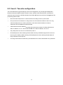
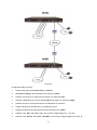
8.3
Case II: Two-site configuration....................................................................................96
Appendix.........................................................................................................................................99
9.1
Keypad Default Settings for IP PBX............................................................................99
9.2
Managing with CLI Commands...................................................................................99
9.2.1
Introduction.........................................................................................................99
9.2.2
Console Interface ...............................................................................................99
9.2.2.1
Connection...............................................................................................100
x
9.2.2.2
Login ........................................................................................................100
9.2.2.3
Basic Commands.....................................................................................100
CLI Command: ....................................................................................................................................100
CLI Command: ....................................................................................................................................100
CLI Command: ....................................................................................................................................101
CLI Command: ....................................................................................................................................101
9.2.2.4
Admin Commands ...................................................................................101
CLI Command: ....................................................................................................................................101
CLI Command: ....................................................................................................................................101
9.2.2.5
PBX Commands ......................................................................................102
Import CLI Command:.........................................................................................................................103
Export CLI Command:.........................................................................................................................103
9.3
IP PBX Voicemail System Menu Tree.......................................................................106
xi
1 Introduction
1.1 Overview
PLANET IPX-2000 series IP PBX system are designed and optimized for the enterprise, and SMB
daily communications. The IPX-2000 is the next generation voice communication platform for the small
to medium enterprise. Designed as an open, scalable, and highly reliable telephony solution, the
IPX-2000 series are able to accept 200 extension registrations, and effectively meeting scales from
various enterprises. Designed to run on a variety of VoIP applications, the IPX-1800 and IPX-2000
provides centralized call control, auto-attendant, voice conferencing, PSTN, and IP-based
communications.
The IPX-2000 integrates up to 8 FXO to become a feature-rich PBX system that supports seamless
communications between existing PSTN calls, analog, IP phones and SIP-based endpoints
The IPX-2000 system integrates telephony call processing, call control, voice mail, and a widely PBX
application programming interface into a highly scalable architecture designed to support both
traditional circuit-based and the Internet telephony service within a distributed enterprise
communications network.
With IPX-2000 system, standard SIP phones can be easily integrated in your office; plus the
auto-config feature, you may integrate our IP Phone series - VIP-254T/VIP-254T, and the ATA (analog
telephone adapter) series - VIP-156/VIP-157 to build up th e VoIP network deployment in minutes.
Allowing distributed IP technology to meet traditional voice services, with proactive management
interface, the IPX-2000 system in the daily business processes, enterprises can make people more
productive, more intelligent tasks, and more customer satisfaction.
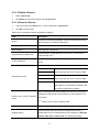
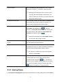
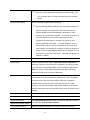
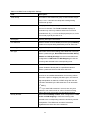
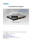
1.2 Physical Interfaces
Figure 7. Front Panel of IPX-2000
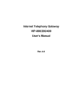
Figure 8. Rear Panel of IPX-2000
100-240 Volt, 50-60 Hz
Power cord
IPX-2000
2 x slots integrates up 8 FXO
4 ports per daughter card, numbered from right to
Telephony interface ports
the left. The rightmost port at slot 0 is port 1 and
FXO module the leftmost port at slot 1 (if installed) is port 8. FXO
ports are to be connected to FXS jacks on wall or
analog PBX using RJ-11 cables.
USB ports
1 external port with compliance to USB 1.1/2.0. Plug in a USB
hard drive for voicemail backup from the internal one
WAN
Connect to a broadband modem or a WAN router
LAN
Connect to a LAN switch
Table 1. Physical interfaces description of IP PBX
2
2 Managing with Web Interface
The factory default of LAN IP address is 192.168.1.1. Connect to LAN port and the configuration Web
interface is at https://192.168.1.1/. Once connected, the browser will ask for accepting a certificate.
Click Yes to see the home page. Type in the default administrator ID and password (both are admin) to
log in for administration. The administrator password can be changed in the User Management ->
User.
1.
Click admin in the Login ID.
2.
Change the password in Password.
3.
Click Apply to change the password.
Note: For the system security, please change the password after the first log-in.
After login, you will see four icons, Add Account Wizard, Add Route & Trunk, Mass Extensions
Adding and Customize Setup. The first three icons can lead you step by step to configure some basic
settings of IP PBX. Click the Customize Setup icon to see all the PBX configurations into detail.
Administrator can click
on the top-left side of the webpage to go back to the home page of IP PBX
Web Interface.
3
3 Wizard Configuration
With IP PBX Wizard configuration, the administrator can set basic configurations for IP PBX easily.
With basic setup, IP PBX can function, and connect to the relevant devices and trunks. The Wizard
Configuration including Add Account Wizard, Add Route & Trunk and Mass Extension Adding.
When entering Wizard configuration, you will see
at the bottom of each page that helps
you to configure with Wizard. Any configuration change in Wizard requires clicking
at the
bottom of the homepage.
3.1 Add Account Wizard
In Add User & Device page, the administrator can setup usergroups, users and devices. You can
follow the following steps to finish configuration. After finishing configuration, click
at the
bottom of the homepage to take the configuration effect.
Step 1: Add User Group
1.
Enter a group ID and then click ADD.
2.
The name will show in the table of the webpage.
3.
Click the name to view the edit page.
4.
Enter settings shown in Table 3-1.
5.
Click Back to return to the ADD USER GROUP page.
For deleting a usergroup, select a group ID and click DEL.
Note: Make sure there is no user associate with the usergroup, or it cannot be deleted.
Click Next to add a user.
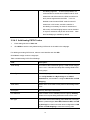
Table 3-1Add Usergroup Settings
Field
Description
Description
Arbitrary description information. Click SET to add/update
4
the information.
Associated Trunks 1
Select routegroups and outbound trunks accessible by this
usergroup. Note the order matters the hunting sequence in
run-time.
Routegroup: display available routegroups.
Trunk: Display available trunks.
Group ID: The default number is “0”. A trunk with Group ID
“0” does not form a balance group with any other trunks in
Group 0. If Group ID is 1~9, trunks with the same Group ID
form a usage balance group.
Weight: the weight of a trunk to be selected in a trunk
balance group for an outgoing call.
Click
or
to add or delete the associate trunks.
After add all trunks, click APPLY.
) If there is not any appropriate SIP trunk and PSTN
trunks to select, you may assign trunks at Setp 5:
Assign Trunk in Add Route & Trunk wizard
configuration after trunks are created in the previous
step.
Reachable User Groups
Select a usergroup and click ADD that is reachable from this
usergroup. By default, only users in the same usergroup can
reach one another.
) If there is not any appropriate usergroup to select,
come back later to revise this selection, once more
usergroups have been created.
Associated PBX Features 2
Select PBX features enabled to this usergroup.
Member List
Show the users associated with this usergroup.
Auth. Dial Passcode
Select and enter a password in number for caller to have the
same privilege as this usergroup to dial out.
1
2
Please refer to 6.6, 6.7, and 6.8 for details.
Please refer to 7 for details.
5
Setp 2: Add User
1.
Enter settings shown in Table 3-2.
2.
Click ADD to see the user information in the table of the webpage.
For deleting a user, select a Login ID and click DEL.
Click Next to choose a device.
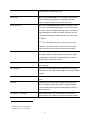
Table 3-2 Add User Settings
Field
Description
Login ID
A unique ID containing alphabets, numbers, and underscore
only without spaces; 20 characters maximum. This is the ID
for personal configuration through IP PBX Web
management.
Name
Name of the user, either a real or a virtual one, e.g. Alice Lee
or Conference Room.
Password
Password for the user to access IP PBX Web management.
Description
Arbitrary description information.
E-mail Address
E-mail address of the user for voicemail notification.
Attach Voicemail in E-mail Notification
Select to enclose the message received in the notification
e-mail as an attachment.
Usergroup
Select the usergroup this user belongs to.
) If there is not any appropriate usergroup to select,
come back later to revise this selection if no
appropriate usergroup could be chosen for now.
Step 3: Choose Device
Based on the devices you have, click ADD IP PHONE or ADD ANALOG PHONE, and Next to add/set
the device.
Note: If selecting ADD ANALOG PHONE, the wizard will skip to Step 5.
6
Step 4: Add Device
1.
Enter a device name in the Device ID box.
2.
Select Auto Provision if you want to enable Automatic Client Configuration.
3.
Click ADD to see the newly added device in the table of the webpage, or to see the Enable
Automatic Client Configuration (ACC) page if Auto Provision is selected.
Enter settings shown in Table 3-3 ACC (Automatic Client Configuration) Settings and click ENABLE.
Note: Consult with your vendor to make sure your SIP phone support Auto Provision function.
For deleting a device, select a device ID and click DEL.
Note: Make sure there is no extension associate with the device, or it cannot be deleted.
Click Next to set a device.
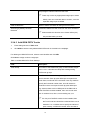
Table 3-3 ACC (Automatic Client Configuration) Settings
Field
Description
Vendor Prefix
Ask your IP Phone vendor for the Prefix. e.g. eip7012.
MAC Address
MAC address of the device.
Supplementary Configuration
Codec Preference
Supplementary configuration files for IP Phone. The file name
must start with “psc-“.
Preference order of supported codec and packet times of the
phone.
VAD is a technique that detects absence of audio and conserves
bandwidth by preventing the transmission of "silent packets" over
Enable Voice Activity Detection
the network.
(VAD)
) Select if your IP Phone supports VAD.
DTMF mode
Choose a DTMF mode used by the phone.
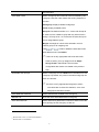
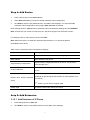
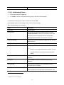
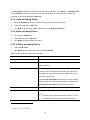
Setp 5: Add Extension
3.1.5.1 Add Extension of IP Phone
1.
Enter settings shown in Table 3-4.
2.
Click ADD to see the newly added extension in the table of the webpage.
7
For deleting an extension, select an extension number and click DEL.
Click Finish to finalize all the settings, and go back to the homepage.
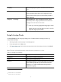
Table 3-4 Add Extension of IP Phone Settings
Field
Description
Extension Number
A unique line number composed of digits only, e.g. 101; 20
digits maximum. This is the login ID on the device
configuration side.
Associated Device
Select the Device this extension associates with.
User 3
Select the user this extension associates with.
) If there is not any appropriate users to select, one can
come back later once the expected user has been
added.
Password
Password of this extension. Same password must be
configured on the device side as well.
Pickup Group
The usergroup that the extension can pick up. The
extension can set a usergroup that when any extension in
the usergroup rings, the extension can press *8 to pick up
the call in ringing state.
Select Include Reachables check box to be able to pickup
calls that belong to other usergroups which is configured in
Reachable User Groups of the selected usergroup.
Language
Preferred language for system instructions heard from the
extension.
Voicemail
Select enable to allocate voicemail account for the
extension.
Voicemail PIN
PIN to access voicemails. This is mandatory if above
voicemail option is enabled.
Max Voicemail Space
Enter maximum space in KBytes for voicemail. Enter 0 or
leave it as blank for not limiting the voicemail space. The
3
Please refer to 6.1 for details.
8
voicemail will be recorded until the storage is full.
Disable Fast Bridging
Select to disable express media forwarding.
) With Fast Bridging feature enabled, if the two parties
involved in a call (for example, one IP extension and
one SIP trunk) use different DTMF modes
(RFC2833/SIP INFO/Inband), inline transfer (*#) or
2nd-dialing might fail. To avoid such problem, it is
recommended to set the same DTMF mode for all IP
extensions and SIP trunks in the IPBX, as well as for
all IP phones registered to the IPBX.
If it is not
feasible to set the same DTMF mode for some IP
extensions or SIP trunks, and inline transfer or
2nd-dialing is necessary for those IP extensions or
SIP trunks, the Fast Bridging feature can be disabled
on a per IP extension and per SIP trunk basis. Note
that Fast Bridging is enabled by default.
Try Peer-to-peer RTP
If click YES, IP PBX will attempt to notify the two peers in a
conversation to try peer-to-peer RTP transmission. This is
suggested as long as phones support INVITE or UPDATE
method during a connected call to save the resource of IP
PBX. However, only SIP INFO DTMF mode phones should
enable this since other DTMF modes require IP PBX being
RTP relay server to support in-line transfer.
DTMF Mode
Choose preferred DTMF mode for this extension. Currently
supported types include RFC2833, SIP INFO, and in-band
tone. It must match configuration on the device side.
) In-band DTMF mode consumes the limited DSP
resource when using a highly compressed codec,
such as G.729 or G.723.1. Therefore, calls will not
connect with such setting if DSP is not installed.
Although using a low-complexity codec such as G.711
does not require DSP, DTMF detection still takes
considerable CPU resource and impacts several
system specs. Be cautious when configuring an
extension with in-band DTMF mode.
9
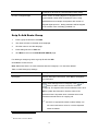
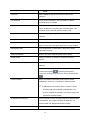
3.1.5.2 Add Analog Phone
1.
Enter settings shown in Table 3-5.
2.
Click ADD to see the newly added analog phone in the table of the webpage.
For deleting an analog phone, select a POTS port and click DEL.
Click Finish to finalize all the settings, and go back to the homepage.
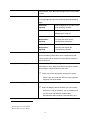
Table 3-5 Add Analog Phone Settings
Field
Description
POTS Port
FXS port index.
Pickup Group
The pickup group that the extension belongs to. Select
Include Reachables check box to be able to pickup calls
that belong to other usergroups which is configured in
Reachable User Groups of the selected usergroup.
Extension Number
A unique line number composed of digits only, e.g. 101; 20
digits maximum.
Unavailable Timeout
Timeout for ringing before a call is answered.
User 4
Select a user that this extension associates with.
) If there is not any appropriate users to select, one can
come back later once the expected user has been
added.
Language
Preferred language for system instructions heard from the
extension.
Voicemail
Select Enable to allocate voicemail account for the
extension.
Voicemail PIN
PIN to access voicemails. This is mandatory if above
voicemail option is enabled.
Max Voicemail Space
Enter maximum space in KBytes for voicemail. Enter 0 or
leave it as blank for not limiting the voicemail space. The
4
Please refer to 6.1 for details.
10
voicemail will be recorded until the storage is full.
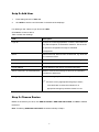
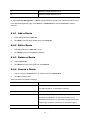
3.2 Add Route & Trunk
In Add Route & Trunk page, the administrator can setup routes, routgroups and trunks. Moreover,
worktime and IVR are included in this part for assigning to trunks. You can follow the following steps to
finish configuration. After finishing configuration, click
at the bottom of the homepage to
take the configuration effect.
Step 1: Add Route
1.
Enter settings shown in Table 3-6.
2.
Click ADD to see the newly added route in the table in the webpage.
For deleting a route, select a route ID and click DEL.
Click Next to set a routegroup.
Table 3-6 Add Route Settings
Field
Description
Route ID
A unique ID containing alphabets, numbers, and underscore
only without spaces; 16 characters maximum.
Description
Arbitrary description information.
Destination Number Pattern 5
A destination number pattern consisting of digits, digit set,
and wildcard characters, e.g. 9NXXXXXX matches any
7-digit called number starting from a digit larger or equal to 2
and with an extra prefix digit 9.
Prefix
A sequence of digits to be prefixed to the final dialed number
after stripping. Using 9NXXXXXX as an example route
pattern with number of stripped digits equal to 1 and prefix
1408, dialing 95270001 will be 14085270001 when it
actually got dialed out.
A special prefix character “w” could be used for PSTN trunks
to pause 0.5 second during dialing. Say, 4 leading
5
For more information about the available digit set and wildcard characters, please refer to Table 6-7.
11
consecutive “w” result in 2 seconds delay before dialing.
Number of Stripped Digits
Select number of leading digits to be stripped from the
original dialed number when matches this route. Using
9NXXXXXX as an example route pattern with number of
stripped digits equal to 1, dialing 95270001 will be stripped
to be 5270001 when it actually got dialed out.
Setp 2: Add Route Group
1.
Enter a group ID and then click ADD.
2.
The name will show in the table of the webpage.
3.
Click the name to view the edit page.
4.
Enter settings shown in Table 3-7.
5.
Click Back to return to the ADD ROUTE GROUP page.
For deleting a routegroup, select a group ID and click DEL.
Click Next to choose a trunk.
Note: Make sure there is no route associate with the routegroup, or it cannot be deleted.
Table 3-7 Add Routegroup Settings
Field
Description
Description
Arbitrary description information. Click SET to add/update
the information.
Associated Routes 6
Select routes belonged to this routegroup. Click
or
button to add or remove a route to or from the
routegroup. The right box lists current selected routes. Click
SET to update the information. Note the order of the
selected routes is important since it decides which route
would be matched first for an outgoing call.
) If there is no appropriate routes to select initially, one
can come back later to revise it, once the expected
routes are added.
6
Please refer to 6.4 for details.
12
Setp 3: Choose Trunk
In the Choose Trunk page, click SIP TRUNK, ANALOG PSTN TRUNK or ISDN PSTN TRUNK to see
one of the following pages to add various types of trunks.
Setp 4: Add Trunk
3.2.4.1 Add SIP Trunks
1.
Enter settings shown in Table 3-8.
2.
Click ADD to see the newly added SIP trunk in the table in the webpage.
For deleting a SIP trunk, select a trunk identifier and click DEL.
Click Next to assign trunks to usergroups.
Table 3-8 Add SIP Trunk Settings
Field
Description
Trunk Identifier
A unique number consisting of digits only. Usually give the
phone number issued by the ITSP for consistency.
Description
Arbitrary description information.
Auth. Name
Specify the name for authentication if different to the Trunk
Identifier.
Auth. Password
Give the password used for authentication on the remote
SIP proxy or registrar. Usually this is given by the ITSP.
Dynamic Peer
Select if the trunk is a passive trunk which means the
registration will be from a dynamic remote peer. Typical
application is to accept registration from an IP PBX at a
remote site with dynamic IP address. Once the remote IP
PBX registers, calls from local to remote can be made
reversely over the trunk.
SIP Proxy IP
Specify IP address (or fully qualified domain name) and UDP
SIP Proxy Port
port of the remote SIP proxy, which usually refer to the SIP
server on the ITSP side.
Registration Required
Select if registration to a registrar is required to activate the
trunk. This is true for a remote IP PBX or an ITSP account,
13
however, may be not required in case of a SIP gateway.
SIP Registrar IP
Specify IP address (or fully qualified domain name) and UDP
SIP Registrar Port
port of the remote SIP registrar, which usually refer to the
SIP server on the ITSP side (same as proxy).
Language
Preferred language for system instructions heard from the
trunk.
DID Type
DID means direct inward dialing (also called DDI in Europe).
Select a preferred type, None DID, Extension DID, DID by
Number DID by Privilege or Centrex DID from the list and
then enter configuration in DID Prefix and DID Stripping to
have the incoming calls directed to the corresponding trunk.
None DID
When selected None DID, all incoming calls will enter IVR
system instead of directly dial to a specified extension.
Select a preferred IVR from IVR list for this trunk.
Extension DID
When selected Extension DID, select an extension in the
list to be an unconditional destination for incoming calls to
this trunk. If prefix or stripping has been given, the result of
digit manipulation is dialed in a DTMF string after the call
has been answered by the DID extension as an automatic
2nd dialing.
) If you set a DID extension in a trunk, then only that
extension can use this trunk to call out, and all incoming
calls to this trunk will connect to that extension directly.
DID By Number
When selected DID By number, enter configurations in DID
Prefix and DID Stripping to have the incoming calls
directed to the corresponding extension derived by number
manipulation. The SIP trunk numbers is therefore regarded
as the direct line of the extension.
DID By Privilege
When selected DID By Privilege, select a usergroup in the
list as the privilege of inbound calls from this trunk. Enter
configuration in DID Prefix and DID Stripping to have the
incoming calls redirected to dial out.
DID Prefix
A digit string to be prefixed to the incoming called number
after stripping.
DID Stripping
A number of leading digits to be stripped from the original
14
called number. Click All to strip all digits of the original called
number.
Centrex DID
Select this function to make the numbers of
incoming/outgoing calls more flexible by prefixing/stripping
digits.
All-number
Select a digitmap ID for calls via the
Digitmap
trunk changing numbers.
Default Number
Enter digits for calls from this trunk
displaying this caller ID.
IVR List 7
Inbound
Select a digitmap ID to have the
Manipulation
incoming calls direct to the
Digitmap
corresponding extensions.
Outbound
Select a digitmap ID to have the
Manipulation
outgoing calls display the
Digitmap
corresponding numbers.
Associate an IVR menu with incoming calls to this trunk.
This is mandatory unless the trunk is configured for DID.
Leave it blank and the system will automatically create an
IVR for the trunk.
Usergroup 8 of Privilege
When disabled DID, click a usergroup in the list whose
reachability to other usergroups and trunks will be used as
the privilege of inbound calls from this trunk.
) There may not be appropriate usergroups to select
initially. One can come back later once the expected
usergroup has been added.
Disable Fast Bridging
Select to disable express media forwarding.
) With Fast Bridging feature enabled, if the two parties
involved in a call (for example, one IP extension and
one SIP trunk) use different DTMF modes
(RFC2833/SIP INFO/Inband), inline transfer (*#) or
7
8
Please refer to 7.12 for details.
Please refer to 6.1 for details.
15
2nd-dialing might fail. To avoid such problem, it is
recommended to set the same DTMF mode for all IP
extensions and SIP trunks in the IPBX, as well as for
all IP phones registered to the IPBX.
If it is not
feasible to set the same DTMF mode for some IP
extensions or SIP trunks, and inline transfer or
2nd-dialing is necessary for those IP extensions or
SIP trunks, the Fast Bridging feature can be disabled
on a per IP extension and per SIP trunk basis. Note
that Fast Bridging is enabled by default.
3.2.4.2 Add Analog PSTN Trunks
1.
Enter settings shown in Table 3-9.
2.
Click ADD to see the newly added analog PSTN trunk in the table in the webpage.
For deleting an analog PSTN trunk, select a trunk identifier and click DEL.
Click Next to assign trunks to usergroups.
Table 3-9 Add Analog PSTN Trunk Settings
Field
Description
Trunk Group
ID number of this PSTN trunk group. A valid number ranges
from 1 to 31. It should not overlap with existing ISDN PSTN
trunk groups.
Trunk Type
Select the port type, FXO or FXS. If selecting FXS, users
can see By Number and By Privilege in the DID of
Extension list, and be able to configure DID Prefix and DID
Stripping.
Trunk Ports
Select one or more FXO or FXS ports for this Analog PSTN
trunk.
Description
Arbitrary description information.
Port Selection
Click to search for an available port in the group. Rotating
means to force ports being selected in turns to even cost.
DID Type
DID means direct inward dialing (also called DDI in Europe).
Select a preferred type, None DID, Extension DID, and DID
by Privilege from the list and then enter configuration in DID
Prefix and DID Stripping to have the incoming calls
16
directed to the corresponding trunk.
None DID
When selected None DID, all incoming calls will enter IVR
system instead of directly dial to a specified extension.
Select a preferred IVR from IVR list for this trunk.
Extension DID
When selected Extension DID, select an extension in the
list to be an unconditional destination for incoming calls to
this trunk. If prefix or stripping has been given, the result of
digit manipulation is dialed in a DTMF string after the call
has been answered by the DID extension as an automatic
2nd dialing.
) If you set a DID extension in a trunk, then only that
extension can use this trunk to call out, and all incoming
calls to this trunk will connect to that extension directly.
DID By Privilege
When selected DID By Privilege, select a usergroup in the
list as the privilege of inbound calls from this trunk. Enter
configuration in DID Prefix and DID Stripping to have the
incoming calls redirected to dial out.
DID Prefix
A digit string to be prefixed to the incoming called number
after stripping.
DID Stripping
A number of leading digits to be stripped from the original
called number. Click All to strip all digits of the original called
number.
Language
Preferred language for system instructions heard from the
trunk.
IVR List 9
Associate an IVR menu with incoming calls to this trunk.
This is mandatory unless the trunk is configured for DID.
Leave it blank and the system will automatically create an
IVR for the trunk.
Usergroup 10 of Privilege
When disabled DID, click a usergroup in the list whose
reachability to other usergroups and trunks will be used as
9
10
Please refer to 7.12 for details.
Please refer to 6.1 for details.
17
the privilege of inbound calls from this trunk.
) There may not be any appropriate usergroups to select
initially. One can come back later to revise it, once the
expected usergroups are added.
Caller ID Detection
Select to detect the Caller ID calling from PSTN lines.
Answering by Battery Reversal
If selected, billable time will count from the call is answered.
Detection
) Please enable this function when Central Office (CO)
site provides battery reversal.
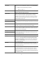
3.2.4.3 Add ISDN PSTN Trunks
1.
Enter settings shown in Table 3-10.
2.
Click ADD to see the newly added ISDN PSTN trunk in the table in the webpage.
For deleting an ISDN PSTN trunk, select a trunk identifier and click DEL.
Click Next to assign trunks to usergroups.
Table 3-10 Add ISDN PSTN Trunk Settings
Field
Description
Trunk Group
ID number of this ISDN trunk group. A valid number ranges
from 1 to 31. It should not overlap with existing Analog
PSTN trunk groups.
Trunk Channels
The Trunk Channels is the logical range of the sum of B
and D channels. Each physical ISDN port occupies three
Trunk Ports, two B and one D channels. User only needs to
specify the B channel number here, since D channel is
reserved in the 3rd trunk port for each physical ISDN port.
E.g. Assume there are four ISDN ports in the PBX and no
other FXO/FXS modules installed, then one can set each
pair of numbers here, like 1,2 but excluding 3,6,9,12.
) If a four-port FXO/FXS module is also installed, then
the Trunk Ports here should be numbered from 5 to 16
instead of 1 to 12. Make sure to specify the indices of
ports correctly, or PBX will not start. One can refer to
18
the POTS Setting page before configuration.
Description
Arbitrary description information.
Port Selection
Select to search for an available port in the group. Rotating
means to force ports being selected in turns to even cost.
DID Type
DID means direct inward dialing (also called DDI in Europe).
Select a preferred type, None DID, Extension DID, DID by
Number DID by Privilege or Centrex DID from the list and
then enter configuration in DID Prefix and DID Stripping to
have the incoming calls directed to the corresponding trunk.
None DID
When selected None DID, all incoming calls will enter IVR
system instead of directly dial to a specified extension.
Select a preferred IVR from IVR list for this trunk.
Extension DID
When selected Extension DID, select an extension in the
list to be an unconditional destination for incoming calls to
this trunk. If prefix or stripping has been given, the result of
digit manipulation is dialed in a DTMF string after the call
has been answered by the DID extension as an automatic
2nd dialing.
) If you set a DID extension in a trunk, then only that
extension can use this trunk to call out, and all incoming
calls to this trunk will connect to that extension directly.
DID By Number
When selected DID By number, enter configurations in DID
Prefix and DID Stripping to have the incoming calls
directed to the corresponding extension derived by number
manipulation. The SIP trunk numbers is therefore regarded
as the direct line of the extension.
DID By Privilege
When selected DID By Privilege, select a usergroup in the
list as the privilege of inbound calls from this trunk. Enter
configuration in DID Prefix and DID Stripping to have the
incoming calls redirected to dial out.
DID Prefix
A digit string to be prefixed to the incoming called number
after stripping.
DID Stripping
A number of leading digits to be stripped from the original
called number. Click All to strip all digits of the original called
number.
19
Language
Preferred language for system instructions heard from the
trunk.
IVR List 11
Associate an IVR menu with incoming calls to this trunk.
This is mandatory unless the trunk is configured for DID.
Leave it blank and the system will automatically create an
IVR for the trunk.
Usergroup 12 of Privilege
When disabled DID, clicks a usergroup in the list whose
reachability to other usergroups and trunks will use as the
privilege of inbound calls from this trunk.
) There may not be any appropriate usergroups to select
initially. One can come back later to revise it, once the
expected usergroups are added.
Setp 5: Assign Trunk
In Assign Trunk page, all usergroups display here. The administrator can assign trunks to any
usergroup at this stage.
1.
Click a group ID to see the Assign Trunk Management.
2.
Enter settings shown in Table 3-11.
3.
Click
or
to add or delete the associate trunks. After adding all trunks, click APPLY.
Note: The order of the assigning trunks matters the hunting sequence in run-time.
Table 3-11 Assign Trunk Settings
Field
Description
Routegroup
Click to select available routegroups.
Trunk
Click to select available trunks.
Group ID
The default number is “0”. A trunk with Group ID “0” does not
form a balance group with any other trunks in Group 0. If
Group ID is 1~9, trunks with the same Group ID form a
usage balance group.
11
12
Please refer to 7.12 for details.
Please refer to 6.1 for details.
20
Weight
The weight of a trunk to be selected in a trunk balance group
for an outgoing call.
3.3 Mass Extension Adding
The Mass Extension Adding Management page helps the administrator to add many extensions and
assign users for these extensions under a usergroup and a device. After finishing configuration, click
at the bottom of the homepage to take the configuration effect.
Note: Make sure the range of extension numbers does not exist in Extension of IP Phone or user Login
ID, or the configuration will fail to continue.
Step 1: Add User & Extension
1.
Enter the digits for the starting extension.
2.
Click a number in the Number of EXT list for the mass extension adding.
3.
Click a usergroup in the USERGROUP list.
4.
Select enable to allocate voicemail account for the extension.
5.
Click an IP phone device in the DEVICE list.
6.
Select to enable Try-Peer-to-peer RTP. If click INVITE or UPDATE, IP PBX will attempt to notify
the two peers in a conversation to try peer-to-peer RTP transmission.
7.
Click a usergroup in the Pickup Group list.
8.
Select Include Reachables check box to enable pickup calls that belong to other usergroup
which is configured in Reachable User Groups of the selected usergroup.
9.
Choose preferred DTMF mode for extensions. Currently supported types include RFC2833, SIP
INFO and Inband.
10.
Click ADD, and IP PBX will start to add these extensions automatically.
11.
Click Back to the homepage.
21
4 System Configuration
This section describes how to configure system parameters used by IP PBX. Click Customize Setup
after login the web interface to configure the following system parameters.
4.1 PBX System
The PBX System page briefs IP PBX status to the administrator. Firmware versions, IP addresses of
WAN and LAN interfaces, and default gateway router are shown in this page. Click PBX System to
see the basic information of IP PBX.
4.2 Time Setup
The Time Setup page allows administrator to configure time zone and date for IP PBX. With correct
time setup, functions such as IVR, worktime, and voicemail can present the actions at the right time.
Select System -> Time Setup to see the current setting of time zone and date.
4.2.1 System Time Zone
1.
Click a region/country in the Time Zone list.
2.
Click Apply in System Timezone Setup.
3.
Go to System -> Shutdown, select Rebooting After Shutdown and Click Yes to activate
changes.
4.2.2 Real Time Clock (RTC) Setup
1.
Click year, month, day, hour, minute, and second in the correspondent list.
2.
Click Apply in Real Time Clock Setup.
Note: When reset the time 15 minutes later than the time showed in RTC Setup, the system will ask for
re-login.
4.3 On-board WAN Setup
The On-board WAN Setup page allows administrator to configure WAN network interface for IP PBX.
Select System -> On-board WAN Setup, and the current setting of WAN network interface is
displayed, e.g. type, IP address etc.
22
Unless the LAN Only is selected, you can choose one of the three options, Static IP, DHCP, and
PPPoE from the Type list for your configuration. Select LAN Only check box to disable WAN, and only
default router and DNS settings are applicable. Select MAC Clone to change the WAN MAC address.
Select Yes to allow WAN to respond PING request.
4.3.1 Static IP
You can click Static IP in the Type list, and manually configure the following information:
•
IP Address
•
Netmask
•
Default gateway IP address
•
Primary, secondary or third DNS servers
Click Apply to submit.
4.3.2 DHCP
Simply click DHCP in the Type list, and click Apply. The acquired IP address, netmask, default
gateway and DNS server information will show when revisit this page later.
4.3.3 PPPoE
1.
Click PPPoE in the Type list.
2.
Enter a user name and its password in User Name and Password boxes.
3.
Click Apply.
The PPPoE dialing will start right away. When there is an active connection, the page will show the
acquired IP address, network mask, default gateway and DNS server information.
4.3.4 Allow WAN to Respond PING
Select this option if appropriate and click Set. If enabled, the WAN port of IP PBX will respond PING to
the originator.
4.3.5 LAN Only
Select LAN Only to disable WAN IP settings but allow the configuration of default gateway and
primary/secondary/third DNS servers.
23
4.3.6 MAC Clone
Select MAC Clone and enter a MAC/physical address to change the WAN MAC address.
4.4 On-board LAN Setup
The On-board LAN Setup page allows administrator to configure LAN network interface for IP PBX.
1.
Select System -> On-board LAN Setup to see the current settings of LAN network interface.
2.
Enter a new IP address and network mask.
3.
Click Apply to change the settings.
Note: By default IP PBX grants IP addresses to LAN devices via DHCP, and translates those
addresses into its WAN IP address for access beyond the LAN subnet. Make sure to change
DHCP pool and LAN routing (if any) accordingly after changing the system LAN IP subnet. After
configuration, go to Service -> IP PBX Service, and click Restart to activate the changes.
4.5 LAN Routing
To enable static routing among LAN subnets, enter network information and the IP address of the
corresponding gateway in the IP PBX’s LAN. It is important to assure that the given gateway IP
address sits in the IP PBX’s LAN. Each subnet requires an entry even multiple subnets share the same
gateway, unless masking does the same.
Examples are adding IP Route IDs net1 and net2 with parameters 192.168.128.0/255.255.255.0,
192.168.129.0/255.255.255.0, shared gateway 192.168.1.254 respectively. Or, IP Route ID net1n2
with 192.168.128.0/255.255.254.0 and gateway 192.168.1.254 would do the same. Added routes
enable routing immediately after clicking Add. However, the IP PBX Service needs to be restarted to
regard calls from designated LAN subnets as LAN traffic. Go to Service -> IP PBX Service, and click
Restart to regard calls as LAN traffic.
4.5.1 Add a Route
1.
Enter the IP Route ID, Network, Netmask, and Gateway.
2.
Click Add to have the newly added route in IP Route ID.
24
4.5.2 Edit a Route
1.
Edit the information in a row.
2.
Click Apply in the row to update the information.
4.5.3 Delete a Route
1.
Select a route ID.
2.
Click Delete to remove the route ID from the IP Route ID column.
4.6 Dynamic DNS Setup
Dynamic WAN IP address causes difficulty for inbound connections from remote clients or IP PBX
systems. A popular work-around is to adopt domain names provided by Dynamic DNS service
providers and run a client on or behind the gateway router (or IP PBX). It is required to apply an
account and create a hostname in the account before configuration.
Click Enable, give account information and refresh interval to activate a Dynamic DNS client. The
client then uses Username and Password to access its account and update periodically the
Hostname with the latest WAN IP address at DynDNS or 3322.net Service.
4.6.1 Enable Dynamic DNS
Typical hostname has a form of <hostname>.dyndns.org or <hostname>.3322.net. The refresh interval
is usually between 60 – 600 seconds depending on the volatility of WAN IP assignment.
1.
Click Enable.
2.
Click DynDNS or 3322.net in the Service list.
3.
Enter the Username, Password, and Hostname.
4.
Click Apply.
4.6.2 Disable Dynamic DNS
Click Disable, and then click Apply.
25
4.7 QoS Setup
To assure the bandwidth reserved for the outgoing VoIP traffic over regular data traffic from LAN, the
QoS Setup page offers three parameters to characterize the WAN link. The default QoS setting is
disabled because these parameters must be correctly given according to the actual WAN speed.
4.7.1 Enable QoS
1.
Click Enable.
2.
Enter the WAN Uplink Speed, WAN Downlink Speed, and Uplink VoIP Reserved (bandwidth).
3.
Click Apply.
For a popular 2M/256K ADSL program, the WAN uplink speed would be 256 and the WAN downlink
speed would be 2048. The Uplink VoIP reserved could be, say, 192 out of the total 256 kbps to allow 2
concurrent G.711 calls. Following is the table of WAN speed related to various codecs.
Codec Information
Bandwidth Calculations
Codec & Bit Rate
Codec
Codec
Mean
Voice
Voice
Packets
Bandwidth
(Kbps)
Sample
Sample
Opinion
Payload
Payload
Per
Required
Size
Interval
Score
Size
Size (ms)
Second
(Kbps)
(Bytes)
(ms)
(MOS)
(Bytes)
(PPS)
G.711 (64 Kbps)
80
10
4.1
160
20
50
87.2
G.729 (8 Kbps)
10
10
3.92
20
20
50
31.2
G.723.1 (6.3 Kbps)
24
30
3.9
24
30
34
21.9
G.723.1 (5.3 Kbps)
20
30
3.8
20
30
34
20.8
G.726 (32 Kbps)
20
5
3.85
80
20
50
55.2
G.726 (24 Kbps)
15
5
60
20
50
47.2
4.7.2 Disable QoS
Click Disable, and then click Apply.
4.8 Virtual Server
You can configure IP PBX as a virtual server for remote users to access services such as the Web or
FTP at your local site via Public IP Addresses. With proper settings, IP PBX can automatically redirect
inbound traffic from WAN to local servers configured with private IP addresses. In other words,
26
depending on the requested service (TCP/UDP) port number, the IP PBX redirects the external service
request to the appropriate internal server (located at one of your LAN's Private IP Address).
To enable access servers in LAN from a machine beyond WAN, select System -> Virtual Server to
configure port mappings. Service ID names the service. Protocol and Port specify the TCP/UDP port
number on WAN IP to be forwarded to the Forward to Port of Forward to IP in LAN. Say 192.168.1.5
is a Mail Server to be seen from outside, one should configure TCP port 25 to be forwarded to
192.168.1.5 port 25.
Note: Following ports are default server ports in use: TCP port 9, 7788, 80, 53, 23, 443 and 13422;
UDP port 1024, 9, 53, 67, 5060 and 69.
4.8.1 Add a Service
1.
Enter the Service ID, Protocol, Port, Forward to IP, and Forward to Port.
2.
Click Add to add the newly service in the Service ID.
Note: the usage of port range: using the syntax from-port : to-port. For example, enter the following
for the TCP ports 6881 to 6999. It should be 6881:6999.
4.8.2 Edit a Service
1.
Change any information in a row.
2.
Click Apply in the row to update the information.
4.8.3 Delete a Service
1.
Select a service ID.
2.
Click Delete to remove the service from the Service ID.
4.9 Maintenance
This page includes maintenance functions of IP PBX, including Storage Backup, SIP UA, CDR Log,
System Events, and Active Calls.
4.9.1 Storage Backup
To back up internal main storage, the administrator can back up the internal main storage to USB Mass
storage or NFS server. You can select to keep or remove CDR and/or voicemails after backup.
27
4.9.1.1 Back up to USB Mass Storage
Click USB Mass Storage, and then BACKUP to follow the instructions to insert the USB connector of
an external USB drive. After a confirmation of the insertion, backup starts a few seconds later if the
external USB drive is accessible and has enough free space. If the backup is successful, a new folder
(yyyy-mm-dd-hhmmss, eg. 2007-06-26-151100) will be created in ippbx-backup folder on the external
drive. After the backup, remove the USB connector of the external drive.
4.9.1.2 Back up to NFS Server
1.
Click NFS Server.
2.
Enter a URL path in NFS Directory Path.
3.
Click Backup to have the internal main storage stored in the NFS server.
4.9.2 SIP UA
SIP UA lists the registration status of each client/remote IP PBX, and the IP Address/Port from where
they register. SIP trunk registrations, if any, also show at the end of the list. The Dynamic column
shows the listed IP address is dynamic or static. Reg. Progress is the response code and message if
registration has been attempted but not successful so far. Slave Registrar column is used only under
the stackable mode. It indicates with which slave box a SIP client is registered. Blank means a client is
registered to the master box locally. IP PBX supports share-line function and all information of
share-line extension/trunk is recorded on SIP UA page, To remove the specific registered
extension/trunk ID, please click Delete button in that row.
Table 4-1 The Registration Status of SIP UA
IP PBX
The Description of Reg. Progress
UAS
Empty
If there is no registration activities existing.
401 Unauthorized
Authentication failed.
407 Authentication
Authentication required.
Required
UAC
Empty
If there is no registration activities existing.
Status code and
The response information is depended on UAS.
message from UAS
28
4.9.3 CDR Log
The CDR(Call Detail Record) Log shows each call record including Calling and Dialed Numbers,
Caller ID, Destination Interface(trunk if outbound) in use, epochs when the call was made,
answered and ended, and which yield the Call Duration and Billable Time. The Result denotes the
disposition of a call like answered or not. The administrator can also click Get File to export the record
as a *.csv file, click Delete CDR to remove all records and click Show CDR to display all records on
the screen.
4.9.4 System Events
The log records an audit entry in the audit trail whenever certain events occur, such as service reload,
firmware upgrade, administrator logging on, logging off, and accessing resources from NTP, DNS,
DHCP, and PPPoE service.
4.9.5 Active Calls
The Active Calls page shows current active calls. Columns Client and Party indicate the involved
extensions or trunks of a call. State shows the state of a call, while Service gives the current action of
the listed Client.
Table 4-2 The State of Active Call
Field
Description
Caller
Show the caller’s extension number, port number, or SIP trunk ID.
Caller state
Dial
The client is caller.
IVR
Calls from FXO are picked up by Auto-Attendant.
Pause
The client is being paused for some time.
Prompt
The client is being prompted for a pre-recorded audio.
Voicemail
The client enters voicemail service.
Meet-me
The client enters meet-me service.
Busy Call-back
The client enters busy call-back service.
ACD
The client enters ACD service.
Trunk
Shows trunk ID that is using in this call.
Callee state
Answer
Callee
Show the callee’s extension number, port number, or SIP trunk ID.
Answer Time
Show the answer time of active calls.
The client is callee.
29
4.10
Firmware Upgrade
The version of the running PBX firmware could be found in System -> Firmware Upgrade. To upgrade
current firmware, click Browse to locate a release file obtained from the vendor, and click Upgrade to
have the latest version of PBX firmware.
Note: Consult with your IP PBX service provider for upgrade procedure.
Note: Do not change the firmware file name, otherwise the system will reject it.
4.11
Stackable Management
IP PBX is scalable and allows you to enlarge capacity by stacking up to four IP PBX boxes to form a
cluster.
4.11.1 Operation Modes
IP PBX provides three modes, standalone mode, master mode and slave mode. The default mode is
standalone mode while there is no cluster and IP PBX box works independently. Once a cluster is
formed, only one IP PBX box runs in master mode, and rest of boxes run in slave mode in the cluster.
For instance, with full-capacity case, there would be one master box and 3 slave boxes in a cluster.
Select System -> Stackable to see the current operation mode of each IP PBX box.
4.11.2 Consolidated Management
Stackable Management page of the master box not only indicates IP addresses of current slave boxes
in a cluster but also allows you to add new slave boxes to the cluster or remove slave boxes from the
cluster. You can simply manage a cluster in Stackable Management page of the master box.
Within a cluster, any extension/user update of configuration information to the master box would affect
all slave boxes automatically. As a result, you shall only configure the master box to take control over
the whole cluster in most cases. Meanwhile, all boxes within the same cluster share the same
registration information and work as one single box.
Note: For SIP and PSTN trunks, and Meet-me conferences, you need to configure them respectively
on each box in stack. It is similar to how you configure them in standalone mode.
Note: For Meet-me conferences in stack, do not enter the same room number in slave and master
boxes, though the function need to be configured respectively.
30
4.11.3 Configuration Procedure
The following examples illustrate how to configure a stack.
4.11.3.1 Case I: Stack multiple IP PBX boxes from scratch
1.
Ensure all boxes have factory default settings before being stacked.
2.
Ensure all boxes have TCP routing to each other via LAN interfaces if they are in different local
networks.
3.
Select one of the boxes to be the master box. Others are slave boxes consequently.
4.
For each slave box, go to System -> Stackable page to specify the master’s IP address and click
Apply. Make sure to configure slave boxes before assigning to master box.
5.
For the master box, go to System -> Stackable page. Select Enable Master Mode check box.
6.
Enter IP address and port of a slave box, and then click Add. If clients support SIP 305 or SIP
302 response, select the By 305 Use Proxy or By 302 Moved Temporarily check box in
Registration Load Balance.
Do this step again if more than one slave box is stacked.
7.
After adding all slave boxes, click Apply.
8.
Go to Service -> IP PBX Service and click Restart to reflect the changes.
All boxes are stacked and a cluster is formed. You can start to configure extensions etc. on master box
to make internal calls possible. You can also configure SIP and PSTN trunks on each box to enable
inbound and outbound calls. Any configuration change in stack requires Reload in Service -> IP PBX
Service of master box.
In order to share SIP and FXO PSTN trunks with other boxes, you need to do the following settings.
For instance, a FXO PSTN trunk (with a route pattern) is configured on box A and assigned to some
usergroups. You would like to share this FXO PSTN trunk with box B.
1.
On box B, configure a route with the pattern equals to the one associated with this FXO PSTN
trunk, and then assign this route to the routegroup associated with the intra trunk from box B
toward box A.
2.
Click Reload in Service -> IP PBX Service of master box.
To explain step one more clearly, for example, box A is 192.168.1.100 and box B is 192.168.1.101.
There is a FXO PSTN trunk “pstn1” with a route pattern “9./1” 13 configured on box A. In order to share
this FXO PSTN trunk among box A and B, on box B we can configure a route “BoxA-pstn1” with pattern
13
9./1 means pattern is 9. and number of stripped digits is 1.
31
“9./0” 14 and assign it to the routegroup “_192168001101_192168001100” which associates with the
intra trunk “_192168001101_192168001100” 15 .
4.11.3.2 Case II: Stack a new IP PBX box with an existing running box
This case means that there is a standalone box up running for a while. Now you would like to add a
new box to form a cluster. Therefore, the standalone box will become a master box later.
1.
Ensure the new box has factory default settings before being stacked.
2.
Ensure the new box has TCP routing to the existing box via LAN interface if they are in different
local networks.
3.
Now, backup the IP PBX configuration on the existing box. Then restore this configuration to the
new one.
4.
On new box, remove all trunk configurations including routes and routegroups, and all Meet-me
conference configurations first.
5.
Go to System -> Stackable of the new box, specify master’s IP address and click Apply.
6.
Go to System -> Stackable of the existing box, select Enable Master Mode check box, enter IP
address and SIP port of the new box, and then click Add.
7.
Click Apply.
8.
Go to Service -> IP PBX Service of the existing box, and click Restart to reflect the changes.
The existing box turns to be a master box and the new box is a slave box in the cluster.
4.11.3.3 Case III: Add new slave boxes to an existing stack
Similar to Case II, you can also add more slave boxes to an existing cluster.
4.11.3.4 Remove slave boxes from stack
1.
Go to System -> Stackable of the master box.
2.
Select IP address of a slave box you would like to remove in Slave Peers, and then click Delete.
3.
Click Apply.
4.
Go to Service -> IP PBX Service of the master box, and click Restart to reflect the changes.
The cluster no longer owns the removed box. The removed box gets off the cluster and would turn
back to be standalone. Moreover, the master box would also turn back to be standalone if all slave
boxes are removed and the cluster does not exist any more.
14
Here, please note that we always use 0 for number of stripped digits.
You probably notice IP addresses of two boxes meshed by an intra trunk determine name of the intra trunk.
In this case, the name of intra trunk from box B (192.168.1.101) toward box A (192.168.1.100) is
_192168001101_192168001100. Meanwhile, the routegroup associated with this intra trunk has the same name.
15
32
4.12
Shutdown
In System -> Shutdown, you can shutdown the machine by clicking YES, or reboot the machine by
selecting the Rebooting After Shutdown check box and clicking YES. In case the software reboot
fails, you can also press the hardware Reset button. It is advised to shut down IP PBX system before a
power-off.
Note: If the hardware RESET button is hold for 5 seconds, the system will revert to factory default.
4.13
Logout
Logout button,
, locates at the top-right of the webpage. Administrator can logout, and go
back to the login page by clicking it.
Note: The GUI will automatically log out after 15 minutes, if you do not do any action.
33
5 Service Configuration
This section describes details to configure various services built in the IP PBX.
5.1 NTP Service
Select Service -> NTP Service to specify a NTP server for network time synchronization. You can
enable or disable NTP service at any time.
5.1.1 Enable NTP Service
1.
Click Enable.
2.
Select the Automatic check box to use server pool at pool.ntp.org; or, enter a fully qualified
domain name or the IP address of a NTP server.
3.
Click Apply.
5.1.2 Disable NTP Service
Click Disable, and click Apply.
5.2 SNMP Service
Select Service -> SNMP Service to specify Simple Network Management Protocol (SNMP)
parameters for network status retrieval. You can enable or disable SNMP service at any time.
5.2.1 Enable SNMP Service
1.
Click Enable.
2.
Enter System Location, System Administrator Contact, SNMPv2 Read-only Community
with allowed network specifications, and also those of the SNMPv2 Read-write Community.
3.
Click Apply.
5.2.2 Disable SNMP Service
Click Disable, and click Apply.
34
5.3 STUN Service
IP PBX has a built-in STUN client to solve NAT problems. Select Service -> STUN Service to specify a
Simple Traversal of UDP through NATs (STUN) server for NAT traversal. You can enable or disable
STUN Service at any time.
5.3.1 Enable STUN Service
1.
Click Enable.
2.
Enter a fully qualified domain name or the IP address of a STUN server.
3.
Click Apply.
4.
Go to Service -> IP PBX Service, and click Restart to reflect the changes.
5.3.2 Disable STUN Service
1.
Click Disable.
2.
Enter the fully qualified domain name or the static IP address of the external WAN interface.
Usually this address refers to the static WAN IP address if there is a NAT device between the IP
PBX and the Internet. If the WAN port of IP PBX directly connects to Internet or it is unused, leave
the address blank.
3.
Click Apply.
4.
Go to Service -> IP PBX Service, and click Restart to reflect the changes.
5.4 TFTP Service
Select Service -> TFTP Service to view the current status of TFTP Service. You can enable or disable
TFTP Service at any time.
5.4.1 Enable TFTP Service
Click Enable, and then click Apply to manage files, e.g. upload and download files to and from the IP
PBX. Uploaded files can then be retrieved through TFTP Service.
5.4.1.1 Change Directory
Current directory is shown in the field on the right side of Directory, for instance, it is /.at the beginning.
Click a directory in the Directory list to change to a different folder.
35
Note: The default directory is /. Initially, you may not be able to change the directory, since no folder is
created under /. yet.
5.4.1.2 Add a Folder
1.
Click a directory under which you want to add a new folder in the Directory list.
2.
Click Add Folder.
3.
Enter a folder name in the pop-up dialog box, e.g. myfolder.
4.
Click OK to see the newly added folder in the Directory list, e.g. /myfolder/.
5.4.1.3 Delete a Folder
1.
Click a directory of a folder in the Directory list.
2.
Click Delete Folder to remove the folder from the Directory list.
Note: A folder cannot be deleted if there is still file inside.
5.4.1.4 Download a File
1.
Click a directory in the Directory list.
2.
Click a file in the Download / Delete File From The Above Folder list.
3.
Click Get File to download the file.
5.4.1.5 Delete a File
1.
Click a directory in the Directory list.
2.
Select a file in the Download / Delete File From The Above Folder list.
3.
Click Delete File to remove the file.
5.4.1.6 Upload a File
1.
Click a directory in the Directory list.
2.
Click Browse.
3.
Select a directory in the Look in list, and then a file.
4.
Click Open.
5.
Click Put File to upload the file.
Now, the uploaded file should appear in current directory and is displayed in the Download / Delete
File From The Above Folder list.
Note: The maximum file size for uploading a file to PC#1 is 12M, and to PC#2 is 6M.
5.4.2 Disable TFTP Service
Click Disable, and then Apply.
36
5.5 DHCP Service
Select Service -> DHCP Service to view the current status of the DHCP Service. You can enable or
disable the DHCP Service at any time.
Note: If the IP PBX was shut down abnormally, Select Service -> DHCP Service and click Apply, or
Go to Service -> IP PBX Service, and click Restart to activate the DHCP service.
5.5.1 DHCP Service
5.5.1.1 Enable DHCP Service
Click Enable, choose the main interface offering addresses, and then Apply to configure DHCP
settings.
5.5.1.2 Disable DHCP Service
Click Disable and click Apply.
5.5.2 Add New
5.5.2.1 Add DHCP Range
1.
Click Add New tab.
2.
Enter a pool name (must have an alphabet initial) in Pool Name.
3.
Select Range or Single-host to enter an IP address of the host with MAC, if the binding is
intended for a specific host only.
4.
Enter a DHCP range of addresses available for lease in IP. The right address box will not show if
Single-host is selected.
5.
Optionally, DHCP options 16 could be configured by entering an option code and value in
Code,Value and click
. The new DHCP option will show in the Options list. To delete an
option, choose it from the Options list and click
6.
after the box.
Click Add at the bottom of the page to commit changes.
You can see the newly added DHCP POOL displayed in the DHCP POOL list.
5.5.2.2 Edit DHCP Range
1.
16
Click any pool name in the DHCP POOL list to see the settings on the right.
Refer to RFC 2132 for the details of available DHCP options.
37
2.
Edit the settings.
3.
Click Update to change the settings.
5.5.2.3 Delete DHCP Range
1.
Click any pool name in the DHCP POOL list.
2.
Click Delete to remove the pool name from the DHCP POOL list.
5.5.3 Show Leased Clients
Click the Show Leased Clients tab to see all leased LAN IP addresses and client details.
5.6 IP PBX Service
In Service -> IP PBX Service, you can click the Operations tab to reload, backup, restore, restart or
revert the IP PBX configuration, or click the Settings tab for the IP PBX parameters settings.
5.6.1 Operations
Select Service -> IP PBX Service, and then click the Operations tab.
5.6.1.1 Reload IP PBX Configuration
Click Reload, and IP PBX will reload the configuration once there is no active call. If there is any active
call, it will retain up to 3 minutes, and then IP PBX will reload. This is the most frequently used function
in this page since any IP PBX configuration change has to be reloaded to take effect.
5.6.1.2 Backup IP PBX Configuration
Click Backup, and IP PBX archives and encrypts current configuration into a time-stamped backup file
under tftpboot root directory. To secure configuration files, download them to a local host through the
Get File function in Service -> TFTP Service once a while. Select the PBX Settings Only check box
for only back up Configurations in PBX, which are parts mainly from User Management to Feature in
the tree view; clear the check box to back up both PBX and system (interfaces and services) settings.
Note: Do not change the configuration file name, or the Restore function will reject the configuration
file.
5.6.1.3 Restore IP PBX Configuration
Click a configuration backup file in the list, click Restore, and IP PBX will restore the configuration as
current setup. After restoring, the system will ask for reboot the PBX service, click Yes to reboot IP
PBX.
38
5.6.1.4 Restart IP PBX Configuration
Click Restart, and the IP PBX Service will restart completely. Currently active calls will be
disconnected immediately. This function is rarely required unless the network setting has been
changed, or the service operates abnormally without problematic configuration could be identified.
5.6.1.5 Revert IP PBX Configuration
Click Revert, and IP PBX will erase current IP PBX settings, DDNS, QoS, STUN service and revert
configuration back to the factory default. Note the reversion affects IP PBX service only, but not other
system services such as DHCP, TFTP, and NTP. The backup IP PBX configuration files under TFTP
remain intact after reversion, so that one can restore to a specific time if a backup file had been
generated then.
To revert the whole system back to the factory default, hold the hardware RESET button more than 5
seconds. All of the configuration settings will be re-set exactly the way they are when users receive the
IP PBX from providers. Users have to re-configure the IP PBX from scratch again. If one needs to
restore the backup configuration after factory default, he/she must download the backup configuration
file to the local computer in Service -> TFTP Service page.
5.6.2 Settings
Select Service -> IP PBX Service, and then click the Settings tab to configure IP PBX parameters.
After the configuration, go to Service -> IP PBX Service, and click Restart to activate changes.
Table 5-1 IP PBX Configuration Settings
Field
Description
PBX SIP Port
Specify the UDP port where the SIP service listens on.
RTP Port Range
Limit the UDP ports used by the IP PBX for media
transport.
) The port range needs to have at least equals to the
(number of extensions (also count shared-lines) +
number of SIP trunks) * 2. If selecting Enable Video
Codec, the total amount needs to multiply by 2 to
have the least requirements for RTP port range.
Insufficient range of ports may cause call blocking
due to port depletion.
Max/Default Expiration Time
Guard and advertise SIP registration respectively.
PBX Caller ID
The default Caller ID for an unknown incoming call.
39
Enable Video Codec
Select if there will be video clients registering to the
system
Support Devices Multiplex Call-ID
Select to force discrimination of SIP tags. Do this only
when there is such a client device in the system and other
devices supporting the same. Otherwise, one may find the
special device only got registered with this option but other
clients or even SIP trunks fail due to such change. Clear
the box if you are not sure.
Max Active Users
Enter a number for registration admission control to limit
the maximum number of active registered clients.
Max Active Calls
Enter a number for call admission control to limit the
maximum number of concurrent calls.
Max Wireless Calls
Enter a number to limit the calls made by explicitly
specified wireless extensions.
MAX CDR Size
Enter maximum space in KBytes available for CDR.
IP TOS Value
Set the TOS value in the IP header of RTP packets
originated from IP PBX.
Call Keep Alive
Enter a time in second to periodically confirm the call is still
connected. The time is between 10 and 180 seconds.
Registered Keep Alive
Enter a time in second to confirm the registration status
periodically. The time is between 10 and 180 seconds.
NAT Traversal Keep Alive
Enter a time in seconds to retain NAT hole punched
periodically. The time is between 10 and 180 seconds.
Disable WAN Bandwidth Saver
Select to disable attempts to use low-bit-rate codec
(G.729A or G.723.1) for remote parties.
Disable DSP saver for LAN calls
Select to honor the preferred codec of caller’s phone
instead of overriding by DSP utilization concerns.
Enable DNS SRV Resolution
Select to enable looking up IP of dynamic clients or trunks
by DNS Service records before their successful
registrations.
Disable Line-in-use Call Back
PBX supports call back function when an extension
without multi-line function is in use. Select to disable
Line-in-use Call Back function.
Disable Exponential Backoff in SIP
Select to disable exponential SIP retransmission.
Retransmission
40
6 IP PBX Configuration
This section introduces steps to provision the IP telephony part of the IP PBX. Note that reloading
configuration is required in order to make new configuration effective 17 .
6.1 User Group Configuration
A usergroup is a logically grouping of users and their privileges. For instance, one could have couple of
usergroups in an IP telephony network, e.g. Sales, Marketing, Administration, Accounting, and
Engineering, etc. Each usergroup associates with a set of PBX features and call routing scopes. In
other words, all users in the same usergroup share the same reachability of PBX features and final
destinations.
Select User Management -> User Group, and one can add, edit, delete or search usergroups. Go to
Service -> IP PBX Service, and click Reload to activate changes.
Note: The maximum usergroup is 64 for PC#1 and 32 is for PC#2.
6.1.1 Add a User Group
1.
Enter a usergroup name beside the Add button, and then click Add.
2.
The name will show in Group ID.
3.
Click the name in Group ID to view the edit page.
4.
Enter settings shown in Table 6-1.
5.
Click Back to return to the Usergroup Management page.
Now, you can see the newly added usergroup displayed in the Group ID.
6.1.2 Edit a User Group
1.
Click a usergroup name in the Group ID.
2.
Edit settings shown in Table 6-1.
3.
Click Back to see the updated information.
6.1.3 Delete a User Group
1.
Select a Group ID.
2.
Click Delete to remove the usergroup from the Group ID.
17
Please refer to 5.6.1.1 for details.
41
6.1.4 Search a User Group
1.
Type a group ID in the Search box, or click a group ID in Group ID list.
2.
Click Go to see the Update page.
Table 6-1 Usergroup Configuration Settings
Field
Description
Group ID
A unique group name containing alphabets, numbers, and
underscore only without spaces; 20 characters maximum.
Description
Arbitrary description information. Click Set to add/update the
information.
Associated Trunks 18
Select routegroups and outbound trunks accessible by this
usergroup. Note the order matters the hunting sequence in
run-time. Click Routegroup: display available routegroups.
Trunk: Display available trunks. Select blocking to block
calls that meet the route patterns in selected routegroup.
Loop back is especially for hop on and off function. Select
loopback to have the number after performing the route
pattern in selected routegroup to go through the rules in
Associate Trunks again. Once find the matched rule, the
number will go to the relevant trunk. Normally, block is at the
very first in the list, while loopback is at the last in the list.
Group ID: The default number is “0”. A trunk with Group ID
“0” does not form a balance group with any other trunks in
Group 0. If Group ID is 1~9, trunks with the same Group ID
form a usage balance group.
Weight: the weight of a trunk to be selected in a trunk
balance group for an outgoing call.
Click
or
to add or delete the associate trunks.
After add all trunks, click Apply.
) If there is not any appropriate SIP trunk and PSTN
trunks to select, come back later to revise selection
once trunks have been created.
18
Please refer to 6.6, 6.7, and 6.8 for details.
42
Reachable User Groups
that is reachable from
Select a usergroup and click
this usergroup. By default, only users in the same usergroup
can reach one another.
) If there is not any appropriate usergroup to select,
come back later to revise this selection, once more
usergroups have been created.
Associated PBX Features 19
Select PBX features enabled to this usergroup.
Member List
Show the users associated with this usergroup.
Auth. Dial Passcode
Select and enter a password in number for caller to have the
same privilege as this usergroup to dial out.
Group Call
A gourp call number is a virtual number that presents all
extensions belong to this group. Enter a group call number
(not an existed extension/service number). Select
extensions and click
to add into the group call. After
adding all extensions, click Apply.
6.2 User Configuration
A user is a logical entity in IP telephony which associates extensions with a usergroup. It also
propagates its attributes such as e-mail and voicemail PIN to extensions. Usually a user refers to a real
person who has a name and e-mail; however, one can always create virtual users to associate with
public extensions. For example, extensions in reception, break room, and lab areas.
Select User Management -> User, and one can add, edit, delete or search users. Go to Service -> IP
PBX Service, and click Reload to activate changes.
6.2.1 Add a User
1.
Click the Add New tab.
2.
Enter settings shown in Table 6-2.
3.
Click Add.
19
Please refer to 7 for details.
43
4.
Click Back to see the newly added user in the Login ID.
6.2.2 Edit a User
1.
Click a user in the Login ID.
2.
Edit settings shown in Table 6-2.
3.
Click Apply.
6.2.3 Clone a User
1.
Click a user in the Login ID.
2.
Click Clone.
3.
Edit settings shown in Table 6-2.
4.
Click Add.
5.
Click Back to see the newly added user in the Login ID.
6.2.4 Delete a User
1.
Select a Login ID.
2.
Click Delete to remove the user from the Login ID.
6.2.5 Search a User
1.
Type a login ID in the Search box, or click a login ID in User list.
2.
Click Go to see the Update page.
Table 6-2 User Configuration Settings
Field
Description
Login ID
A unique ID containing alphabets, numbers, and underscore
only without spaces; 20 characters maximum. This is the ID
for personal configuration through IP PBX Web
management.
Name
Name of the user, either a real or a virtual one, e.g. Alice Lee
or Conference Room.
Password
Password for the user to access IP PBX Web management.
Description
Arbitrary description information.
E-mail Address
E-mail address of the user for voicemail notification.
Attach Voicemail in E-mail Notification
Select to enclose the message received in the notification
44
e-mail as an attachment.
Usergroup
Select the usergroup this user belongs to.
) If there is not any appropriate usergroup to select,
come back later to revise this selection if no
appropriate usergroup could be chosen for now.
Extensions
Show the extensions associated with this user.
6.3 Device Configuration
A device could be an IP phone, gateway, analog telephone adapter, or even another IP PBX, etc. It has
one or more extensions to be registered to the IP PBX.
6.3.1 IP Phone
The DEVICE PHONE MANAGEMENT page lets the administrator to create IP Phone devices. Before
connecting a device to the IP PBX, you need to configure the same account information into the device
through the configuration interface enabled by the device. Select Device -> IP Phone to add, edit,
delete and search devices. Go to Service -> IP PBX Service, and click Reload to activate changes.
6.3.1.1 Add a Device
1.
Enter a device name in the Device ID box, and a URL for fast connection to device configuration
page or description for the device in the Device Administration URL box.
2.
Click Add to see the newly added device in the Device ID.
6.3.1.2 Edit a Device
Once create the device, you can modify its information through the following steps.
1.
Modify the Device Administration URL and click Link as a shortcut to the device administration
URL.
2.
Click Edit to see the Enable Automatic Client Configuration (ACC) page. Table 6-3 is a reference
for detailed ACC settings which is used for auto-configuring IP phones. One can specify the MAC
address and audio preferences of the phone. Note that for phones using HTTP for
auto-configuring, DHCP setting needs a new option 151 with a value of http://<IP PBX LAN
IP>/tftpboot/ in the Code,Value box in Service -> DHCP Service. If the phone uses TFTP for
auto-configuration, the option is 150 by default.
3.
Click Enable to see Enable shows in the Auto Client Conf column. Click Edit and then Disable
to disable the function.
45
6.3.1.3 Delete a Device
1.
Select a Device ID.
2.
Click Delete to remove the device from the Device ID.
6.3.1.4 Search a Device
1.
Type a group ID in the Search box, or click a device ID in Device ID list.
2.
Click Go to see the data.
Table 6-3 ACC (Automatic Client Configuration) Settings
Field
Device
Description
A unique ID containing alphabets, numbers, and underscore only
without spaces; 20 characters maximum.
Vendor Prefix
Ask your IP Phone vendor for the Prefix. e.g. eip7012.
MAC Address
MAC address of the device.
Supplementary Configuration
Codec Preference
Supplementary configuration files for IP Phone. The file name
must start with “psc-“.
Preference order of supported codec and packet times of the
phone.
Enter the information as follows.
Redundant Servers
Proxy IP/FQDN
Specify IP address (or fully qualified domain
Proxy Port
name) and UDP port of the remote IP PBX.
Registrar IP/FQDN
Specify IP address (or fully qualified domain
Registrar Port
name) and UDP port of the remote IP PBX
SIP Domain
Specify the SIP domain used by the proxy
and registrar. If not specified, IP address will
be used as the domain by default.
VAD is a technique that detects absence of audio and conserves
bandwidth by preventing the transmission of "silent packets" over
Enable Voice Activity Detection
the network.
(VAD)
) Select if your IP Phone supports VAD.
DTMF mode
Choose a DTMF mode used by the phone.
IP PBX supports auto adjustment for daylight saving time. To
Daylight Saving
enable this function, the administrator must configure the Daylight
Format, Start Time and End Time. The following example
46
configures daylight saving time for the U,S, adding one hour
starting at midnight on the first Sunday in April and ending at
midnight on the last Sunday of October. Select By weekday of a
specific month on the Daylight Format, set First Sunday of April
at 00 O’clock on the Start Time, and set Last Sunday of October
at 00 O’clock on the End Time.
6.3.2 Extension of IP Phone
The Extension of IP Phone Management page lets the administrator to create extensions. Select
Device -> Extension of IP Phone, and one can add, edit, delete and search extensions. Go to
Service -> IP PBX Service, and click Reload to activate changes.
IP PBX also offers its own extensions Line-in-use Call Back and Transfer Call Back function. For
example, extension A and B are within one IP PBX or a stacked cluster. When extension A calls
extension B, and extension B is in use. Extension A can press 1 to be in the waiting list. Once
extension B finishes the call, IP PBX will ring extension B within a minute. When extension B is picked
up, IP PBX will ring extension A to connect the call. Extension A call also press * to cancel, and will
connect to voice mail.
Note: The IP Phone should disable call waiting (multi-line) function in order to activate the line-in-use
call back function. If the extension B does not disable the call waiting function on IP Phone, when
extension A calls to extension, and extension B is in use, the second line of extension B’s IP
Phone will ring.
For transfer-call-back function, extension A calls to extension B, extension B (transferer) tries to
transfer the call to extension C (transferee). After the transferee’s unavailable timeout reached,
extension B gets re-ringback tone from IP PBX.
Note: To trigger the transfer-call-back-to function, all of the following conditions must be true:
1. It is phone-based ring-transfer.
2. The transferee is a local extension.
3. The transferee does not answer until the unavailable timeout is reached.
4. No forwarding settings to voicemail/extension for the transferee.
6.3.2.1 Add an Extension
1.
Click the Add New tab to set an extension.
47
2.
Enter settings shown in Table 6-4.
3.
Click Add to see the newly added extension.
6.3.2.2 Edit an Extension
1.
Click an extension in the Extension Number.
2.
Edit settings shown in Table 6-4.
3.
Click Apply to see the updated information.
6.3.2.3 Clone an Extension
1.
Click an extension in the Extension Number.
2.
Click Clone.
3.
Edit settings shown in Table 6-4.
4.
Click Add to see the updated information.
6.3.2.4 Delete an Extension
1.
Select an extension numbers.
2.
Click Delete to remove the extension from the Extension Number.
6.3.2.5 Search an Extension
1.
Type an extension number in the Search box, or click an extension number in Device ID list.
2.
Click Go to see the data.
Table 6-4 Device Extension Configuration Settings
Field
Description
Extension Number
A unique line number composed of digits only, e.g. 101; 20
digits maximum. This is the login ID for device registration.
Associated Device
Select the Device this extension associates with.
Password
Password of this extension. Same password must be
configured on the device side as well.
User 20
Select the user this extension associates with.
) If there is not any appropriate users to select, one can
come back later once the expected user has been
added.
Pickup Group
20
The usergroup that the extension can pick up. The
Please refer to 6.1 for details.
48
extension can set a usergroup that when any extension in
the usergroup rings, the extension can press *8 to pick up
the call in ringing state.
Select Include Reachables check box to be able to pickup
calls that belong to other usergroups which is configured in
Reachable User Groups of the selected usergroup.
Line Type
Specify the type of connection, wired or wireless, of the
client with the extension.
Language
Preferred language for system instructions heard from the
extension.
Voicemail
Select enable to allocate voicemail account for the
extension.
Voicemail PIN
PIN to access voicemails. This is mandatory if above
voicemail option is enabled.
Max Voicemail Space
Enter maximum space in KBytes for voicemail. Enter 0 or
leave it as blank for not limiting the voicemail space. The
voicemail will be recorded until the storage is full.
Unavailable Timeout
Timeout for ringing before a call is answered.
Allow LAN Use Only
Check to reject registration and calls from WAN in a SIP ID
same as the extension number. I.e., this extension must be
on LAN.
Disable NAT Traversal
IP PBX uses NAT traversal for outgoing traffics by default.
Select to disable NAT traversal if there is a machine that
could handle NAT issues.
Call Keep Alive
Select to check if the call is still active. Frequency check is
specified in 5.6.2.
Registered Keep Alive
Select to check if the register still exists in a certain time.
Disable Fast Bridging
Select to disable express media forwarding.
) With Fast Bridging feature enabled, if the two parties
involved in a call (for example, one IP extension and
one SIP trunk) use different DTMF modes
(RFC2833/SIP INFO/Inband), inline transfer (*#) or
2nd-dialing might fail. To avoid such problem, it is
recommended to set the same DTMF mode for all IP
49
extensions and SIP trunks in the IPBX, as well as for
all IP phones registered to the IPBX.
If it is not
feasible to set the same DTMF mode for some IP
extensions or SIP trunks, and inline transfer or
2nd-dialing is necessary for those IP extensions or
SIP trunks, the Fast Bridging feature can be disabled
on a per IP extension and per SIP trunk basis. Note
that Fast Bridging is enabled by default.
Try Peer-to-peer RTP
If click YES, IP PBX will attempt to notify the two peers in a
conversation to try peer-to-peer RTP transmission. This is
suggested as long as phones support INVITE or UPDATE
method during a connected call to save the resource of IP
PBX. However, only SIP INFO DTMF mode phones should
enable this since other DTMF modes require IP PBX being
RTP relay server to support in-line transfer.
DTMF Mode
Choose preferred DTMF mode for this extension. Currently
supported types include RFC2833, SIP INFO, and in-band
tone. It must match configuration on the device side.
) In-band DTMF mode consumes the limited DSP
resource when using a highly compressed codec,
such as G.729 or G.723.1. Therefore, calls will not
connect with such setting if DSP is not installed.
Although using a low-complexity codec such as G.711
does not require DSP, DTMF detection still takes
considerable CPU resource and impacts several
system specs. Be cautious when configuring an
extension with in-band DTMF mode.
Advanced Settings
Select to see more optional settings shown below.
Selective Call Blocking
Select Block Anonymous Calls to block all calls without a
Caller ID.
Block one or more calling numbers by entering the calling
numbers and clicking
. Removing the blocked
numbers by clicking the number from the list, and then click
.
Block SIP redirection from the
Select to ignore the forward settings of IP phone and honor
extension
the forward settings of IP PBX.
50
Forward Options
Select Unconditional Call Forward and clicks a default
destination in the list, e.g. Voicemail or Phone Number.
) If selecting Phone Number, enter a number to which
incoming calls are forwarded unconditionally. The
number could be an extension or a PSTN number with
appropriate outbound prefix.
Unavailable Call Forward
Enter a number to which incoming calls are forwarded when
not answered. The number could be an extension or a
PSTN number with appropriate outbound prefix.
Timeout To Next Forward
Enter a period of time in seconds for ringing the extension in
to add the
Unavailable Call Forward. Click
extension in Unavailable Call Forward and the time here
into the list. Remove the extension of Unavailable Call
Forward from the list by clicking
.
) The time must be shorter than Unavailable Timeout,
or the function will not work normally.
Play Unavailable/Line-in-use Forward
Notify the caller that callee is not available and the call is
Prompt
being forwarded to another extension.
Line-in-use Forward
Enter a number to which incoming calls are forwarded when
the extension is busy. The number could be an extension or
a PSTN number with appropriate outbound prefix.
) If the function is enabled, the Line-in-use Call Back
function will be disabled.
Selective Call Forward
Unconditional Call Forwarding according to the calling
number. Enters one or more calling numbers and a
forwarding number, and clicks
. E.g., forward only
calls from 101 to a cellular number, while let the rest enter
the voice mail by default. Selects a forwarding and click
when the forwarding is no longer required.
6.3.3 Analog Phone
The Analog Phone Management page lets the administrator to create analog phones. Select Device
51
-> Analog Phone, and one can add, edit, and delete analog phones. Go to Service -> IP PBX Service,
and click Reload to activate changes. Connect an analog phone to a FXS port and configure the
properties of the port as detailed in Table 6-5.
6.3.3.1 Add an Analog Phone
1.
Click the Add New tab to see the detailed Analog Phone Management page.
2.
Enter settings shown in Table 6-5.
3.
Click Add to see the newly added analog phone in the Extension Number.
6.3.3.2 Edit an Analog Phone
1.
Click a port in POTS Port.
2.
Edit settings shown in Table 6-5.
3.
Click Apply to see the edited information.
6.3.3.3 Delete an Analog Phone
1.
Select a POTS Port.
2.
Click Delete to remove the extension from the POTS Port.
Table 6-5 FXS Extension Configuration Settings
Field
Description
POTS Port
FXS port index.
Extension Number
A unique line number composed of digits only, e.g. 101; 20
digits maximum.
Pickup Group
The pickup group that the extension belongs to. The
extension can set a usergroup that when any extension in
the usergroup rings, the extension can press *8 to pick up
the call in ringing state.
Select Include Reachables check box to be able to pickup
calls that belong to other usergroups which is configured in
Reachable User Groups of the selected usergroup.
Unavailable Timeout
Timeout for ringing before a call is answered.
User 21
Select a user that this extension associates with.
) If there is not any appropriate users to select, one can
come back later once the expected user has been
21
Please refer to 6.1 for details.
52
added.
Voicemail
Select Enable to allocate voicemail account for the
extension.
Voicemail PIN
PIN to access voicemails. This is mandatory if above
voicemail option is enabled.
Max Voicemail Space
Enter maximum space in KBytes for voicemail. Enter 0 or
leave it as blank for not limiting the voicemail space. The
voicemail will be recorded until the storage is full.
Language
Preferred language for system instructions heard from the
extension.
T.38 Enabled
Click Auto, Enable or Disable detecting fax tones in a call.
UDPTL Redundancy Level
Select number of the previous package(s) that will be sent
again. This function only takes effect when T.38 is enabled.
Input/Output Gain
Voice amplification or attenuation in dB scale to adjust
input/output volume.
Advanced Settings
Select to see more optional settings shown below.
Default Codec
Select g711ulaw or g711alaw for connecting to other
devices.
Selective Call Blocking
Select Block Anonymous Calls to block all calls without a
Caller ID
Block one or more calling numbers by typing the calling
numbers and clicking
. Removing the blocked
numbers by clicking the number from the list, and then click
.
Forward Options
Select Unconditional Call Forward and click a default
destination in the list, e.g. Voicemail or Phone Number.
) If selecting Phone Number, enter a number to which
incoming calls are forwarded unconditionally. The
number could be an extension or a PSTN number with
appropriate outbound prefix.
Unavailable Call Forward
Enter a number to which incoming calls are forwarded when
not answered. The number could be an extension or a
PSTN number with appropriate outbound prefix.
Timeout to Next Forward
Enter a period of time in seconds for ringing the extension in
53
Unavailable Call Forward. Click
to add the
extension in Unavailable Call Forward and the time here
into the list. Remove the extension of Unavailable Call
Forward from the list by clicking
.
) The time must be shorter than Unavailable Timeout,
or the function will not work normally.
Play Unavailable/Line-in-use Forward
Notify the caller that callee is not available and the call is
Prompt
being forwarded to another extension.
Line-in-use Forward
Enter a number to which incoming calls are forwarded when
the extension is busy. The number could be an extension or
a PSTN number with appropriate outbound prefix.
Selective Call Forward
Unconditional call forwarding according to the calling
number. Enters one or more calling numbers and a
forwarding number, and click
. E.g., forward only calls
from 101 to a cellular number, while let the rest enter the
voice mail by default. Selects a forwarding and click
when the forwarding is no longer required.
Hot/Warmline
A hot line means that a specified number will be called
immediately when the phone goes off-hook. A warm line
functions similarly except it does so only after a specified
delay expired to allow dialing a different number with the
line.
Enter a number as the direct hot/warm line number, and
optionally, a timeout period in seconds if the warm line
behavior is expected.
6.3.4 IP Phone Firmware
The IP Phone Firmware Management page is for uploading firmware of IP phone. When connecting
an IP phone to PBX, the IP phone can automatically upgrade to the latest firmware once there is a
version available for download on the IP PBX. Select Device -> IP Phone Firmware to add, edit, or
delete IP phone firmware configurations.
6.3.4.1 Add IP Phone Firmware
1.
Enter settings shown in Table 6-6.
54
2.
Click Put File to see the newly added firmware in the table below.
Note: The uploaded file and auto generated file will be displayed at the TFTP Service page under root
directory.
6.3.4.2 Delete IP Phone Firmware
1.
Select a vendor prefix of IP phone.
2.
Click Delete at the top-left side of the table to remove the firmware.
Note: The deleted file and originally auto generated file will be also deleted from the TFTP Service
page under root directory.
Table 6-6 IP Phone Firmware Configuration Settings
Field
Description
Vendor Prefix
Ask your IP phone vendor for the prefix. e.g. eip7012.
Version
Enter the firmware version that is going to be upgraded for
the IP phone, e.g. 1.0.0123
Firmware File to Upload
Click Browse to find a firmware file from the local host.
6.4 Route Configuration
A route is a destination number pattern for outbound call matching. A pattern consists of digits 0-9
(including “-”), “*”, “#”, digit set, and wildcard characters like “.”, “X”, “Z”, and “N”. Table 6-7 explains
digit set and wildcard characters.
Note: The “#” in route pattern is for some PSTN saver lines that may set “#” as their dial pattern. For
most of the IP Phones, press “#” will immediately send out the dialed number.
Table 6-7 Digit Set and Wildcard Characters for Route Patterns
Expression
Description
[<digits>]
Match any single digit listed explicitly. e.g., digit set [13579]
match odd digits. One may use ‘-‘ to indicate a range of
digits, e.g. [2-8].
. (dot)
Match any digit in any length. Usually given in the end of a
pattern to include all numbers matched a specific prefix.
) . (dot) can not be used alone or at the beginning of the
route patterns.
X
Match any single digit from 0 to 9.
55
Z
Match any single digit from 1 to 9.
N
Match any single digit from 2 to 9.
By selecting Route Management -> Route, the administrator can add, edit, delete and search routes
in the Route Management page. Go to Service -> IP PBX Service, and click Reload to activate
changes.
6.4.1 Add a Route
1.
Enter settings shown in Table 6-8.
2.
Click Add to see the newly added route in the Route ID.
6.4.2 Edit a Route
1.
Edit settings shown in Table 6-8 in a row.
2.
Click Apply in the row to update the settings.
6.4.3 Delete a Route
1.
Select a Route ID.
2.
Click Delete to remove the route from the Route ID.
6.4.4 Search a Route
1.
Type a route ID in the Search box, or select a route ID in Route ID list.
2.
Click Go to see the data.
Table 6-8 Route Configuration Settings
Field
Description
Route ID
A unique ID containing alphabets, numbers, and underscore
only without spaces; 16 characters maximum.
Description
Arbitrary description information.
Destination Number Pattern
A destination number pattern consisting of digits, digit set,
and wildcard characters, 32 characters maximum, e.g.
9NXXXXXX matches any 7-digit called number starting from
a digit larger or equal to 2 and with an extra prefix digit 9.
Prefix
A sequence of digits to be prefixed to the final dialed number
56
after stripping. Using 9NXXXXXX as an example route
pattern with number of stripped digits equal to 1 and prefix
1408, dialing 95270001 will be 14085270001 when it
actually got dialed out.
A special prefix character “w” could be used for PSTN trunks
to pause 0.5 second during dialing. Say, 4 leading
consecutive “w” result in 2 seconds delay before dialing.
Number of Stripped Digits
Number of leading digits to be stripped from the original
dialed number when matches this route. Using 9NXXXXXX
as an example route pattern with number of stripped digits
equal to 1, dialing 95270001 will be stripped to be 5270001
when it actually got dialed out.
6.5 Route Group Configuration
A routegroup groups routes into a logical superset of route patterns. Such abbreviation simplifies the
association of multiple routes with a trunk, say, a PSTN line. A route must be included into at least one
routegroup in order to take the route pattern into effect. The administrator can click Group ID,
Description and Associated Routes arrows to sort the order of data.
Select Route Management-> Route Group, and the administrator can add, edit, delete and search
routegroups in the Route Group Management page. Go to Service -> IP PBX Service, and click
Reload to activate changes.
6.5.1 Add a Route Group
1.
Type a route group name and click Add.
2.
Click the route group in Group ID to see the settings.
3.
Enter settings shown in Table 6-9, and click Back.
The newly added route group should be displayed in the Group ID.
6.5.2 Edit a Route Group
1.
Click a route group name in Group ID.
2.
Edit settings shown in Table 6-9.
3.
Click Back to see the updated information.
57
6.5.3 Delete a Route Group
1.
Select a Group ID.
2.
Click Delete to remove the route group from the Group ID.
6.5.4 Search a Route Group
1.
Type a group ID in the Search box, or click a group ID in Group ID list.
2.
Click Go to see the Update page.
Table 6-9 Routegroup Configuration Settings
Field
Description
Group ID
A unique ID containing alphabets, numbers, and underscore
only without spaces; 32 characters maximum.
Description
Arbitrary description information. Click Set to add/update the
information.
Associated Routes 22
Select routes belonged to this routegroup. Click
or
button to add or remove a route to or from the
routegroup. The right box lists current selected routes. Click
Set to update the information. Note the order of the selected
routes is important since it decides which route would be
matched first for an outgoing call.
) If there is no appropriate routes to select initially, one
can come back later to revise it, once the expected
routes are added.
6.6 SIP Trunk Configuration
A SIP trunk refers to a SIP account on a remote call routing or gateway device. A practical example is
an account at an Internet Telephony Service Provider (ITSP) where a call is routed to a SIP client or
off-ramped to an analog subscriber via PSTN. One could also build SIP trunk to a remote IP PBX to
reach its extensions and PSTN ports.
22
Please refer to 6.4 for details.
58
The SIP Trunk Management page allows the administrator to configure SIP trunks used by IP PBX.
Select Trunk -> SIP Trunk, and one can add, edit, delete and search SIP trunks. Go to Service -> IP
PBX Service, and click Reload to activate changes.
6.6.1 Add a SIP Trunk
1.
Click the Add New tab.
2.
Enter settings shown in Table 6-10.
3.
Click Add to see the newly added SIP trunk in the Trunk Identifier.
6.6.2 Edit a SIP Trunk
1.
Click an identifier in Trunk Identifier.
2.
Edit settings shown in Table 6-10.
3.
Click Apply to change the information.
6.6.3 Clone a SIP Trunk
1.
Click an identifier in Trunk Identifier.
2.
Click Clone.
3.
Edit settings shown in Table 6-10.
4.
Click Add to see the updated information.
6.6.4 Delete a SIP Trunk
1.
Click the Trunks tab, and select a trunk identifier.
2.
Click Delete to remove the SIP trunk from the Trunk Identifier.
6.6.5 Search a SIP Trunk
1.
Type a trunk identifier in the Search box, or click a trunk identifier in Group ID list.
2.
Click Go to see the Update page.
Table 6-10 SIP Trunk Configuration Settings
Field
Description
Trunk Identifier
A unique number consisting of digits only. Usually give the phone
number issued by the ITSP for consistency.
Description
Arbitrary description information.
59
Auth. Name
Specify the name for authentication if different to the Trunk Identifier.
) IP PBX do not accept the following characters:
`;~!#$%^*()+|-=\{}[]" ',/<>.
Auth. Password
Give the password used for authentication on the remote SIP proxy or
registrar. Usually this is given by the ITSP.
Dynamic Peer
Select if the trunk is a passive trunk which means the registration will
be from a dynamic remote peer. Typical application is to accept
registration from an IP PBX at a remote site with dynamic IP address.
Once the remote IP PBX registers, calls from local to remote can be
made reversely over the trunk.
SIP Proxy IP
Specify IP address (or fully qualified domain name) and UDP port of
SIP Proxy Port
the remote SIP proxy, which usually refer to the SIP server on the ITSP
side.
SIP Domain
Specify the SIP domain used by the proxy and registrar. If not
specified, IP address will be used as the domain by default.
Registration Required
Select if registration to a registrar is required to activate the trunk. This
is true for a remote IP PBX or an ITSP account, however, may be not
required in case of a SIP gateway.
SIP Registrar IP
Specify IP address (or fully qualified domain name) and UDP port of
SIP Registrar Port
the remote SIP registrar, which usually refer to the SIP server on the
ITSP side (same as proxy).
Language
Preferred language for system instructions heard from the trunk.
DID Type
DID means direct inward dialing (also called DDI in Europe). Select a
preferred type, None DID, Extension DID, DID by Number DID by
Privilege or Centrex DID from the list and then enter configuration in
DID Prefix and DID Stripping to have the incoming calls directed to
the corresponding trunk.
None DID
When selected None DID, all incoming calls will enter IVR system
instead of directly dial to a specified extension. Select a preferred IVR
from IVR list for this trunk.
Extension DID
When selected Extension DID, select an extension in the list to be an
unconditional destination for incoming calls to this trunk. If prefix or
stripping has been given, the result of digit manipulation is dialed in a
DTMF string after the call has been answered by the DID extension as
an automatic 2nd dialing.
60
) If you set a DID extension in a trunk, then only that extension can
use this trunk to call out, and all incoming calls to this trunk will
connect to that extension directly.
DID By Number
When selected DID By number, enter configurations in DID Prefix
and DID Stripping to have the incoming calls directed to the
corresponding extension derived by number manipulation. The SIP
trunk numbers is therefore regarded as the direct line of the extension.
DID By Privilege
When selected DID By Privilege, select a usergroup in the list as the
privilege of inbound calls from this trunk. Enter configuration in DID
Prefix and DID Stripping to have the incoming calls redirected to dial
out.
DID Prefix
A digit string to be prefixed to the incoming called number after
stripping.
DID Stripping
A number of leading digits to be stripped from the original called
number. Click All to strip all digits of the original called number.
Centrex DID
Select this function to have more flexible calling numbers.
All-number Digitmap
Select a digitmap ID for calls via the trunk
changing numbers.
Enter digits for calls from this trunk
Default Number
displaying this caller ID.
Inbound Manipulation
Select a digitmap ID to have the incoming
Digitmap
calls direct to the corresponding extensions.
Outbound
Select a digitmap ID to have the outgoing
Manipulation
calls display the corresponding numbers.
Digitmap
IVR List 23
Associate an IVR menu with incoming calls to this trunk. This is
mandatory unless the trunk is configured for DID. Leave it blank and
the system will automatically create an IVR for the trunk.
Usergroup 24 of Privilege
When disabled DID, click a usergroup in the list whose reachability to
other usergroups and trunks will be used as the privilege of inbound
calls from this trunk.
23
24
Please refer to 7.12 for details.
Please refer to 6.1 for details.
61
) There may not be appropriate usergroups to select initially. One
can come back later once the expected usergroup has been
added.
Disable Fast Bridging
Select to disable express media forwarding.
) With Fast Bridging feature enabled, if the two parties involved in a
call (for example, one IP extension and one SIP trunk) use
different DTMF modes (RFC2833/SIP INFO/Inband), inline
transfer (*#) or 2nd-dialing might fail. To avoid such problem, it
is recommended to set the same DTMF mode for all IP
extensions and SIP trunks in the IPBX, as well as for all IP
phones registered to the IPBX.
If it is not feasible to set the
same DTMF mode for some IP extensions or SIP trunks, and
inline transfer or 2nd-dialing is necessary for those IP extensions
or SIP trunks, the Fast Bridging feature can be disabled on a per
IP extension and per SIP trunk basis. Note that Fast Bridging is
enabled by default.
Advanced Settings
Select to see more settings shown below.
DTMF Mode
Select a preferred DTMF mode, Inband, RFC 2833 or SIP INFO, for
this trunk in the list. This must match configuration on the server side.
If the user does not know the DTMF mode on the server side, select
Auto from the list, and IP PBX will automatically detect the DTMF
mode on this SIP trunk is Inband or RFC2833.
Try Peer-to-peer RTP
Click NO to disable or IP PBX will attempt to notify the two peers in a
conversation to try peer-to-peer RTP transmission. This is suggested
as long as phone and ITSP side support re-INVITE or UPDATE
method during a connected call to save the resource of IP PBX.
However, only SIP INFO DTMF mode should enable this since other
DTMF modes require IP PBX being RTP relay server to support in-line
transfer.
User Agent
Override default User-Agent header content.
From Caller ID
Send the entered number as Caller ID.
Bandwidth Sensitive
Click Bandwidth Sensitive and specify a limit of bandwidth in kbps for
Bandwidth Limitation (kbps)
call admission in Bandwidth Limitation.
Call Admission Control
Select to enable the limitation of concurrent calls for a SIP trunk.
62
Allow <number> Concurrent
Select Call Admission Control and enter a number for allowed
Call(s)
concurrent calls.
Enable ENUM Resolution
Select to use ENUM resolution, or leave it as blank.
Clear Bindings Prior
If failed to the registration and cannot identify any abnormal settings,
Registration
select to un-register before registering again.
Disable NAT Traversal
IP PBX uses NAT traversal for outgoing traffics by default. Select to
disable NAT traversal if media ports in SDP are trusted.
Anti-SIP Blocking
Select to ignore illegitimately inserted CANCEL messages from ISP.
Gateway Trunk
Select to (1) trust the peer if IP matches and (2) retain caller ID.
Call Keep Alive
Select to check if the call is still ongoing in a certain time.
Registered Keep Alive
Select to check the registration status in a certain time.
Delay Before/After
Delay in seconds before and after answering a call from SIP trunk.
Answering
RFC2833 Payload Type
The default payload type is 101. Enter a value between 96 and 127 to
change the default payload type when selecting DTMF mode as RFC
2833 or Auto.
WAN LBR Preference
Select a low bit rate codec to be used as the first priority for outbound
calls. e.g. select Auto to use caller’s low bit rate codec, if any, or G.729
as the first priority.
) To use WAN LBR Preference on a SIP trunk, the WAN Bandwidth
Saver function must be enabled.
6.7 Analog PSTN Trunk configuration
An Analog PSTN trunk group is a logical group of one or more FXO or FXS PSTN subscriber lines
connecting to FXO or FXS ports on IP PBX.
The Analog PSTN Trunk Management page allows the administrator to configure PSTN trunks.
Select Trunk -> Analog PSTN Trunk, and one can add, edit and delete PSTN trunks. Go to Service
-> IP PBX Service, and click Reload to activate changes.
6.7.1 Add an Analog PSTN Trunk
1.
Click the Add New tab.
63
2.
Enter settings shown in Table 6-11.
3.
Click Add to see the newly added Analog PSTN trunk in Trunk Group.
6.7.2 Edit an Analog PSTN Trunk
1.
Click a trunk group in Trunk Group.
2.
Enter settings shown in Table 6-11.
3.
Click Apply to change the information.
6.7.3 Delete an Analog PSTN Trunk
1.
Click the Trunks tab, and select a trunk group.
2.
Click Delete to remove the PSTN trunk from the Trunk Group.
Table 6-11 Analog PSTN Trunk Configuration Settings
Field
Description
Trunk Group
ID number of this PSTN trunk group. A valid number ranges
from 1 to 31. It should not overlap with existing ISDN PSTN
trunk groups.
Trunk Type
Select the port type, FXO or FXS.
Trunk Ports
Select one or more FXO or FXS ports for this Analog PSTN
trunk.
Description
Arbitrary description information.
Port Selection
Click to search for an available port in the group. Rotating
means to force ports being selected by turns to even cost.
DID Type
If selecting FXO, user can see None DID, Extension DID
and DID By Privilege in the DID Type list. If selecting FXS,
users can see None DID, Extension DID and DID By
Privilege in the DID Type list.
None DID
When selected None DID, all incoming calls will enter IVR
system instead of directly dial to a specified extension.
Select a preferred IVR from IVR list for this trunk.
Extension DID
When selected Extension DID, select an extension in the
list to be an unconditional destination for incoming calls to
this trunk. If prefix or stripping has been given, the result of
digit manipulation is dialed in a DTMF string after the call
has been answered by the DID extension as an automatic
64
2nd dialing.
) If you set a DID extension in a trunk, then only that
extension can use this trunk to call out, and all
incoming calls to this trunk will connect to that
extension directly.
DID By Number
When selected DID By number, enter configurations in DID
Prefix and DID Stripping to have the incoming calls
directed to the corresponding extension derived by number
manipulation. The trunk numbers is therefore regarded as
the direct line of the extension.
DID By Privilege
When selected DID By Privilege, select a usergroup in the
list as the privilege of inbound calls from this trunk. Enter
configuration in DID Prefix and DID Stripping to have the
incoming calls redirected to dial out.
DID Prefix
A digit string to be prefixed to the incoming called number
after stripping.
DID Stripping
A number of leading digits to be stripped from the original
called number. Click All to strip all digits of the original called
number.
Language
Preferred language for system instructions heard from the
trunk.
IVR List 25
Associate an IVR menu with incoming calls to this trunk.
This is mandatory unless the trunk is configured for DID.
Leave it blank and the system will automatically create an
IVR for the trunk.
Usergroup 26 of Privilege
When disabled DID, click a usergroup in the list whose
reachability to other usergroups and trunks will be used as
the privilege of inbound calls from this trunk.
) There may not be any appropriate usergroups to select
initially. One can come back later to revise it, once the
25
26
Please refer to 7.12 for details.
Please refer to 6.1 for details.
65
expected usergroups are added.
Delay Before/After Answering
Delay in seconds before and after answering a call from
PSTN trunk.
Forced Disconnection of this Duration
Enter a time in ms for disconnecting the call when there is
(ms) of Silence Detected
no sound for the period of time.
6.8 ISDN PSTN Trunk Configuration
An ISDN PSTN trunk group is a logical group of one or more ISDN subscriber lines connecting to ISDN
ports (RJ45) on IP PBX. Currently only Basic Rate Interface (BRI) ISDN service is supported. BRI
consists of two 64 kb/s B channels and one 16 kb/s D channel for a total of 144 kb/s. This basic service
is intended to meet the needs of most individual users.
The ISDN PSTN Trunk Management page allows the administrator to configure ISDN trunks. Select
Trunk -> ISDN PSTN Trunk, and one can add, edit and delete ISDN trunks. Go to Service -> IP PBX
Service, and click Reload to activate changes.
6.8.1 Add an ISDN PSTN Trunk
1.
Click the Add New tab.
2.
Enter settings shown in
66
Table 6-12.
3.
Click Add to see the newly added ISDN PSTN trunk in the Trunk Group.
The newly added ISDN Trunk shall display in the Trunk Group.
6.8.2 Edit an ISDN PSTN Trunk
1.
Click a trunk group in Trunk Group.
2.
Enter settings shown in
67
Table 6-12.
3.
Click Apply to change the information.
6.8.3 Delete an ISDN PSTN Trunk
1.
Click the Trunks tab, and select a trunk group.
2.
Click Delete to remove the ISDN PSTN trunk from the Trunk Group.
68
Table 6-12 ISDN Trunk Configuration Settings
Field
Description
Trunk Group
ID number of this ISDN trunk group. A valid number ranges
from 1 to 31. It should not overlap with existing Analog
PSTN trunk groups.
Trunk Channels
Each physical ISDN port occupies three channels, two B
and one D channels. The Trunk Channels displays B
channels only. User only needs to select one or more B
channels here. E.g. 1,2 is for the first physical port, 3,4 is for
the second physical port and so on.
Description
Arbitrary description information.
Port Selection
Select to search for an available port in the group. Rotating
means to force ports being selected by turns to even cost.
Switch Type
Supports European switch type by default.
DID Type
DID means direct inward dialing (also called DDI in Europe).
Select a preferred type, None DID, Extension DID, DID by
Number and DID by Privilege from the list and then enter
configuration in DID Prefix and DID Stripping to have the
incoming calls directed to the corresponding trunk.
None DID
When selected None DID, all incoming calls will enter IVR
system instead of directly dial to a specified extension.
Select a preferred IVR from IVR list for this trunk.
Extension DID
When selected Extension DID, select an extension in the
list to be an unconditional destination for incoming calls to
this trunk. If prefix or stripping has been given, the result of
digit manipulation is dialed in a DTMF string after the call
has been answered by the DID extension as an automatic
2nd dialing.
)
If you set a DID extension in a trunk, then only that
extension can use this trunk to call out, and all incoming
calls to this trunk will connect to that extension directly.
DID By Number
When selected DID By number, enter configurations in DID
Prefix and DID Stripping to have the incoming calls
directed to the corresponding extension derived by number
manipulation. The ISDN trunk numbers is therefore
regarded as the direct line of the extension.
69
DID By Privilege
When selected DID By Privilege, select a usergroup in the
list as the privilege of inbound calls from this trunk. Enter
configuration in DID Prefix and DID Stripping to have the
incoming calls redirected to dial out.
DID Prefix
A digit string to be prefixed to the incoming called number
after stripping.
DID Stripping
A number of leading digits to be stripped from the original
called number. Click All to strip all digits of the original called
number.
Language
Preferred language for system instructions heard from the
trunk.
IVR List 27
Associate an IVR menu with incoming calls to this trunk.
This is mandatory unless the trunk is configured for DID.
Leave it blank and the system will automatically create an
IVR for the trunk.
Usergroup 28 of Privilege
When disabled DID, clicks a usergroup in the list whose
reachability to other usergroups and trunks will use as the
privilege of inbound calls from this trunk.
) There may not be any appropriate usergroups to select
initially. One can come back later to revise it, once the
expected usergroups are added.
Caller ID
Leaves it blank to have the default caller ID, or enters a
caller ID that is provided by your ISDN service provider.
6.9 POTS Setting
The POTS Setting page allows users to set the parameters of FXO/FXS/ISDN ports based on the
requirement from the Central Office (CO) site. Users can select impedance from drop-down list and
fine-tune the parameters. Click Apply to save modifications. Go to Service -> IP PBX Service, and
click Restart to activate new settings.
27
28
Please refer to 7.12 for details.
Please refer to 6.1 for details.
70
6.9.1 FXO Port Configuration Settings
Table 6-13 FXO Port Configuration Settings
Field
Description
Type
The type of this port.
Port
The ID number of physical port.
Impedance/CP Tone
The Impedance/CP Tone setting determines the dial tone,
busy tone, and ringback tone to the originating party. Select
the appropriate impedance/call-progress tone for the local
region.
Default Codec
Select g711ulaw or g711alaw for connecting to other
devices.
Input/Output Gain
Voice amplification or attenuation in dB scale to adjust
input/output volume of a PSTN line.
Caller ID Detection
Select to detect the Caller ID calling from PSTN lines.
) When DID to an extension number, it is suggest to
enable this function, or the forwarding settings at
phone side may not work properly.
Answering by Battery Reversal
If selected, billable time will count from when the call is
Detection
answered.
) Please enable this function when Central Office (CO)
site provides battery reversal.
Minimum Disconnection Tone
Minimum volume level of the disconnection tone. If a PSTN
trunk is found to have disconnection problem and low-voice ,
choose a lower dB.
Call Time Restriction
Enter a number (1-1440) in minute to limit the call period. If a
call lasts longer than the time, IP PBX will force to terminate
the call. Enter 0 or leave it blank to disable the function.
1st/ 2nd Frequency of On-cycle Tone
Enter a number in Hz for call disconnection on-cycle tone.
1st/ 2nd Frequency of Off-cycle Tone
Enter a number in Hz for call disconnection off-cycle tone.
Min/Max Duration of On-cycle Tone
Enter a time in ms for minimum or maximum duration of
on-cycle tone.
71
Min/Max Duration of Off-cycle Tone
Enter a time in ms for minimum or maximum duration of
off-cycle tone.
Forced Disconnection of this Duration
Enter a time in ms for disconnecting the call when there is
(ms) of Silence Detected
no sound for the specific period of time.
6.9.2 FXS Port Configuration Settings
Table 6-14 FXS Port Configuration Settings
Field
Description
Type
The type of this port.
Port
The ID number of physical port.
Impedance/CP Tone
The Impedance/CP Tone setting determines the dial tone,
busy tone, and ringback tone to the originating party. Select
the appropriate impedance/call-progress tone for the local
region.
Default Codec
Select g711ulaw or g711alaw for connecting to other
devices.
Input/Output Gain
Voice amplification or attenuation in dB scale to adjust
input/output volume of a PSTN line.
Caller ID Detection
Select to detect the Caller ID calling from PSTN lines.
Answering by Battery Reversal
If selected, billable time will count from when the call is
Detection
answered.
) Please enable this function when Central Office (CO)
site provides battery reversal.
Minimum Disconnection Tone
Minimum volume level of the disconnection tone. If a PSTN
trunk is found to have disconnection problem and low-voice,
choose a lower dB.
Call Time Restriction
Enter a number (1-1440) in minute to limit the call period. If a
call lasts longer than the time, IP PBX will force to terminate
the call. Enter 0 or leave it blank to disable the function.
72
6.9.3 ISDN Port Configuration Settings
Table 6-15 ISDN Port Configuration Settings
Field
Description
Type
The type of this port.
Port
The ID number of physical port.
Impedance/CP Tone
The Impedance/CP Tone setting determines the dial tone,
busy tone, and ringback tone to the originating party. Select
the appropriate impedance/call-progress tone for the local
region.
Default Codec
Select g711ulaw or g711alaw for connecting to other
devices.
Compand Type
Compand standards vary between countries. Select
MULAW or ALAW for the local region.
Signaling
Select Point to point or Point to multipoint depends on
the link type between ISDN service provider and your
device.
Caller ID
Leave it blank to have the default caller ID, or enter a caller
ID that is provided by your ISDN service provider.
6.10
Digitmap Configuration
The digitmap is for Centrex DID in SIP trunks. A pattern consists of digits 0-9 (including “-”), “*”, “#”,
digit set, and wildcard characters like “.”, “X”, “Z”, and “N”. in Route Configuration explains digit set and
wildcard characters.
Note: The “#” in the pattern is for some PSTN saver lines that may set “#” as their dial pattern. For
most of the IP Phones, press “#” will immediately send out the dialed number.
6.10.1 Add a Digitmap
1.
Click the Add New tab.
2.
Enter settings show in Table 6-16.
3.
Click
4.
Click Add to have newly added digitmap.
to see the pattern in the list.
73
6.10.2 Edit a Digitmap
1.
Select a digitmap ID.
2.
Edit settings show in Table 6-16.
3.
Click
or
to add or delete the pattern.
4.
Click
or
to adjust the order of sequence.
5.
Click Apply.
6.10.3 Delete a Digitmap
1.
Select a digitmap ID.
2.
Click Delete to remove the ID.
Table 6-16 Digitmap Configuration Settings
Field
Description
Digitmap ID
A unique ID containing alphabets, numbers, and underscore
only without spaces; 17 characters maximum.
Destination Number Pattern
A destination number pattern consisting of digits, digit set,
and wildcard characters, e.g. 9NXXXXXX matches any
7-digit number starting from a digit larger or equal to 2 and
with an extra prefix digit 9.
Number of Stripped Digits
Number of leading digits to be stripped from the original
number when matches this digitmap. Using 9NXXXXXX as
an example pattern with number of stripped digits equal to 1,
dialing 95270001 will be stripped and change to 5270001.
Prefix
A sequence of digits to be prefixed to the number after
stripping. Using 9NXXXXXX as an example pattern with
number of stripped digits equal to 1 and prefix 1408, dialing
95270001 will change to 14085270001.
A special prefix character “w” could be used for PSTN trunks
to pause 0.5 second during dialing. Say, 4 leading
consecutive “w” result in 2 seconds delay before dialing.
74
7 Feature Configuration
A feature is a logical entity presenting a function module of IP PBX, e.g. meet-me conference, auto
attendant, voice mail, music on hold, etc. Any configuration change to a feature requires clicking
Reload in Service -> IP PBX Service to take effect.
7.1 Call Park
During a call, the callee may want to continue the conversation using another phone. The call park
feature enables so by letting the callee transfer the call to the call park pilot number (*# + Pilot Number).
IP PBX will respond an available park line from the pool of call park numbers to the callee. After that
the callee may hang up current phone, move to another phone, and dial the park line number told by IP
PBX to resume conversation with the caller. If the callee does not call the given park line number to
retrieve his call before timeout, IP PBX will ring the original extension where the callee answered the
call. To configure Call Park feature, select Feature -> Call Park.
1.
Enter settings shown in Table 7-1.
2.
Click Apply.
Table 7-1 Call Park Configuration Settings
Field
Description
Call Park Pilot Number
A unique extension number for call parking, e.g. 700.
Available Parking Lines
An extension pool for call parking, e.g. 701-720 forms a
20-line pool available for system to park calls.
Parking Timeout
Timeout waiting for picking up the parked call
7.2 Life Line
Life line feature allows specification of emergency number patterns to seize a PSTN line with absolute
priority. For example, someone dials an emergency call while all PSTN lines are in use. In such case, if
the called number matches any specified life line pattern, the PSTN line with longest talk time so far will
be disconnected right away to allow the emergency call.
Select Feature -> Life Line to configure life-line feature.
75
7.2.1 Add a Life Line Pattern
1.
Enter settings shown in Table 7-2.
2.
Click Add to see the newly added pattern in the Line Pattern.
7.2.2 Edit a Life Line Pattern
1.
Edit settings shown in a row.
2.
Click Apply at the end of the row to update the information.
7.2.3 Delete a Life Line Pattern
1.
Select a Line pattern.
2.
Click Delete to remove the pattern from the Line Pattern.
Table 7-2 Life line Configuration Settings
Field
Description
Line Pattern
Pattern for emergency numbers.
Note: This is the pattern after digit stripping. For example,
configure 911 here even if users dial 9911 to reach the
911 service over PSTN when the PSTN trunk has an
outbound dialplan of “9.”.
Description
Arbitrary description information.
7.3 Meet-me Conference
Meet-me conference enables conferencing of multiple parties from various devices. A calling party
could reach this virtual conference room by dialing in a conference. Moreover, you can enter the
meet-me conference as administrator or normal user level. Administrator has more privilege during the
conference. Please refer to Table 7-3.
IP PBX allows multiple conference rooms going concurrently using different room numbers. Before
entering a meeting room, the caller has to enter the correct PIN of the room number.
Note: The administrator must drop all parties by pressing *5 when the meeting ends.
Select Feature -> Meet-me Conference to configure meet-me conference feature.
76
7.3.1 Add a Meet-me Conference
1.
Enter settings shown in Table 7-3.
2.
Click Add to add a new conference room.
The newly added room should display in the Room Number.
7.3.2 Edit a Meet-me Conference
1.
Edit settings shown in a row.
2.
Click Apply at the end of the row to update the information.
7.3.3 Delete a Meet-me Conference
1.
Select a room number.
2.
Click Delete to remove the conference room from the Room Number.
Table 7-3 Meet-me Conference Configuration Settings
Field
Description
Room Number
Meeting room number, e.g. 8000.
Description
Arbitrary description information.
PIN to Join
PIN for normal users to join the conference.
During a conference, a normal user has following options:
-
# to quit conference
-
*1 to mute/unmute
-
*9 to log in as the administrator if there is no
administrator dialed in yet.
Administrator PIN
PIN for the administrator of the conference.
During a conference, the administrator has following
options:
-
# to quit conference
-
*1 to mute/unmute
-
*2 to lock/unlock the conference
-
*3 to invite a user into the conference
-
*4 to drop a party from the conference
-
*5 to drop all parties in the conference
77
-
*6 to drop the last invited party by *3
-
** to send DTMF string to the last invited party by
*3. This is useful when the invited party is behind
an IVR system.
7.4 Music On Hold
Music-on-hold (MOH) is used in several occasions for a single purpose—to comfort the waiting party
with music. One could upload some candidate music files and pick one as the default one.
Select Feature -> Music On Hold to manage MOH files.
7.4.1 Music on Hold Management
7.4.1.1 Add a MOH File
Enter settings shown in
1.
Table 7-4.
2.
Click Add to see the newly added file in the MOH ID.
7.4.2 Media File Management
7.4.2.1 Edit a MOH File
1.
Upload Media File: Click Browse to select a file and Click Put File to upload.
2.
Delete Media File: Select a file from the drop-down list and Click Delete to remove it.
3.
Default MOH: Click a MOH ID from the drop-down list and click Set in the row.
7.4.3 MOH ID List
7.4.3.1 Edit a MOH ID
1. Click a file from the Media File and click Apply in the row.
7.4.3.2 Delete a MOH File
1.
Select a MOH ID.
2.
Click Delete to remove the MOH ID from the MOH ID List.
78
Table 7-4 MOH file Configuration Settings
Field
Description
MOH ID
A unique ID containing only alphabets, numbers, and
underscore without spaces; 32 characters maximum.
Media File
Candidate music files in the repository. To upload a new
music file, click Browse to find a Windows PCM (8000 Hz,
16-bit) file from the local host and click Put File. On
successful uploading, the filename will appear in the Media
File list. To delete a media file from the list, choose a file
from the Delete Media File list, and click Delete to remove
it.
Default MOH
Select to use this music file for system default MOH globally.
7.5 Voicemail
IP PBX has a built-in voice mail subsystem with a sophisticated IVR menu. A call to an extension in use
or no answer could be configured to enter voice mail recording procedure. After leaving a message, a
notification e-mail will be sent to the user owns the extension with or without the message in the form of
an attached WAV file. The Message Waiting Indicator (MWI) on IP phones (if any) will be lit. For analog
phones, the user will hear six short beeps before the normal dial tone when picking up the analog
phone. The user could then dial the voicemail pilot number to enter voice mail system to manage
messages such as playback, delete, or move them from inbox to different folders. In addition to
indicating current voice mail capacity on the management page, IP PBX can send an alarm email to
the administrator when the available voice mail space reaches the threshold. To configure Voicemail
feature, select Feature -> Voicemail.
1.
Enter settings shown in Table 7-5.
2.
Click Apply.
Table 7-5 Voice Mail Configuration Settings
Field
Description
Voicemail Pilot Number
Number to access voice mail system IVR, e.g. 6666.
Minimum Message Time
Messages less than this duration will not be saved as a
message. e.g., 3 (sec).
79
Maximum Message Time
Maximum duration allowed for a single message. e.g., 60
(sec).
Maximum number of messages per
Maximum number of messages allowed per extension.
account
SMTP Server
Hostname or IP address of the SMTP server for voicemail
notification.
E-mail from Address
Most SMTP servers require a valid from address to accept a
mailing request.
Voicemail Available Space Check
Select to enable the Alarm Email function described below.
Send Alarm Email when Space Below
Set a threshold in minutes to send an alarm email to the
administrator when the space left is below it.
Voicemail Space Left
Show the available space in Kbytes and minutes.
) The storage inside IP PBX saves not only voice mails
but also some other stuff, such as CDR and logs. The
remained disk space is all for voice mails, and it is the
“maximum” available voice mail space.
SMTP Server Account
Specify an account ID if the SMTP server requires
authentication for outgoing mails.
SMTP Server Password
Specify the account password if the SMTP server requires
authentication for outgoing mails.
7.6 Meet-me Prompts
This page allows replacing built-in meet-me conference prompts with user recordings.
1.
Click a language and a prompt in the corresponding lists.
2.
Click Browse to find a corresponding recording in the local storage.
3.
Click Put File to complete the replacement.
4.
To reset a prompt back to default, click a language and a prompt in the corresponding lists, and
then click Use Default.
Note that the replacement is done for the selected Language and Prompt only and the prompt is
marked “*” in the dropdown list if it is not a default prompt. Currently only following prompts could be
replaced.
80
Table 7-6 Replaceable Meet-me Prompts
Prompt
Description
Get PIN Number
Please enter the conference pin number.
Invalid PIN
That pin is invalid for this conference.
Only Person
You are currently the only person in this conference.
7.7 Voicemail Prompts
This page allows replacing built-in voicemail system prompts with user recordings.
1.
Click a language and a prompt in the corresponding lists.
2.
Find a corresponding recording in the local storage.
3.
Click Put File to complete the replacement.
4.
To reset a prompt back to default, click a language and a prompt in the corresponding lists, and
then click Use Default.
Note that the replacement is done for the selected Language and Prompt only and the prompt is
marked “*” in the dropdown list if it is not a default prompt. Currently only following prompts could be
replaced.
Table 7-7 Replaceable Voicemail System Prompts
Prompt
Description
Login
Welcome to voice mail system, please enter your mailbox.
Password
Password.
Incorrect Mailbox
Login incorrect, please enter your mailbox again.
Good-bye
Good-bye.
Prerecording Introduction
Press star (*) to cancel recording and return to the main
menu. Or, press pound (#) to start recording right away.
Introduction
Please leave your message after the tone. When done,
hang up or press the pound (#) key.
Extension
Extension.
Unavailable
It’s not available.
Busy
It’s on the phone.
81
Lineisdown
Device Unreachable.
Isnotreg
Device Unregistered.
7.8 Broadcast
A user can arrange an event at the exact time in IP PBX. IP PBX will inform all users that set in the
Callee Extensions list by ringing their extensions. For example, one arranges a meeting and wants to
remind all attendants, he/she may enter settings. When the time set in Date/Time is up, IP PBX will call
to the extensions, and then executes the Action to each of the calls. Select Feature -> Broadcast to
configure Broadcast feature.
7.8.1 Add a Broadcast
1.
Click the Add New tab.
2.
Enter settings shown in Table 7-8.
3.
Click Add at the bottom of the page to see the newly added broadcast event in the Events.
7.8.2 Edit a Broadcast
1.
Click the Management tab.
2.
Click an Event.
3.
Edit settings shown in Table 7-8.
4.
Click Apply to change the information.
7.8.3 Delete a Broadcast
1.
Click the Management tab.
2.
Select an Event.
3.
Click Delete to remove the broadcast event from the Events.
Table 7-8 Broadcast Configuration Settings
Field
Description
Event
A unique ID containing alphabets, numbers, and underscore only without
spaces; 32 characters maximum.
Action
Select one of the three actions to execute when the Date/Time is up.
82
Playback: Play the uploaded WAV file in the Customized Media File
box to the callee extensions.
Dial: IP PBX will ring the party set in the Callee Extensions box first,
and then call back to the one in the Dial Extension field to establish a
conversation.
It is suggested to set one number only in the Callee Extensions unless
the extension number in the Dial Extension field is multi-line.
Play default music: Play default music configured in the Music On Hold
page to extensions in the Callee Extensions box.
Customized media File
Upload a *.wav file, if Playback is selected in the Action list.
) The recording format must be 8000 Hz, 16 bit, mono Windows PCM
WAV file.
Dial Extension
Select an extension to call back if Dial is selected in the Action.
Max Retry Times
Maximum redial times if callees did not answer.
Retry Time
A period of time in minutes between two retrying.
Wait Time
Enter timeout in seconds when ringing a callee.
Date/Time
Select a Date/Time to trigger this broadcast event.
Callee Extensions
Intended extensions to be called at the Date/Time. Click
/
to
select/remove the selected callee extension(s) from this list.
7.9 Worktime
Worktime page defines holidays and business hours for generic IVR application. Several groups of
date/time could be defined for different IVR menus. Select Feature -> Worktime to configure Worktime
features.
7.9.1 Add a Worktime
1.
Click the Add New tab.
2.
Enter settings shown in Table 7-9.
3.
Click Add at the bottom of the page.
The newly added worktime should display in the Group ID.
83
7.9.2 Edit a Worktime
1.
Click the Management tab.
2.
Click a Group ID.
3.
Edit settings shown in Table 7-9.
4.
Click Apply to change the information.
7.9.3 Delete a Worktime
1.
Click the Management tab.
2.
Select a Group ID.
3.
Click Delete.
The deleted worktime shall disappear from the Group ID.
Table 7-9 Worktime Configuration Settings
Field
Description
Group ID
A unique ID containing numbers only.
Mode
Select one of the four modes:
1: No work on weekends.
2: Work off and on by turns on Saturdays.
3: Work half-day on Saturdays.
4: Work on all 7 days
General Worktime
The work time from Monday to Friday.
Saturday Worktime
The work time for Saturdays, this field only active when mode is set to 2
or 3.
Optional Worktime
Special holidays or work day. User can set date and its work time, or set
it to a whole-day holiday. Click
/
to select/remove the
selected item(s) from this list.
7.10
Memo Call
A user can set a memo at a specific time, e.g. a morning call, in IP PBX to inform the user or another
user set in the Extension list by call at the time. When the user picks up the phone, IP PBX plays
“voice file” or “music”. The user can also set this memo as a daily routine so that IP PBX informs the
user at the exact time every day. Select Feature -> Memo Call to configure memo calls.
84
7.10.1 Add a Memo Call
1.
Click the Add New tab.
2.
Enter settings shown in Table 7-10.
3.
Click Add at the bottom of the page to see the newly added memo call in the Memo.
7.10.2 Edit a Memo Call
1.
Click the Management tab.
2.
Click a Memo.
3.
Edit settings shown in Table 7-10.
4.
Click Apply to update the information.
7.10.3 Delete Memo Call
1.
Click the Management tab.
2.
Select a Memo.
3.
Click Delete to remove the memo call from the Memo.
Table 7-10 Memo Configuration Settings
Field
Description
Memo
A unique ID containing alphabets, numbers, and underscore only without
spaces.
Extension
Click an extension to call.
Repeat Daily
Select Yes to enable looping playback every day at the exact time.
Action
Select one out of the two available actions for the memo.
Playback: Play the uploaded WAV file in the Customized Media File
box to the extension(s).
Play default music: Play default music configured in the Music On Hold
page to the extension(s).
Customized Media File
Upload a *.wav file, if Playback is selected in the Action list.
) The recording format must be 8000 Hz, 16 bit, mono Windows PCM
WAV file.
85
Max Retry Times
Maximum redial times if callees did not answer.
Retry Time
A period of time in minutes between two retries.
Wait Time
Enter timeout in seconds when ringing a callee.
Date/Time
Select a Date/Time to trigger this memo call.
7.11
Automatic Call Distribution
IP PBX implements Automatic Call Distribution (ACD) by queues and agents. A pool of agents is
created first and then one or more queues could be added with distinct service numbers and a list of
agent extensions. Each agent should be bound with an existed extension to take calls and each queue
could have a specific distribution policy, such as round robin, ring all, least recent, fewest calls, and
random. With such settings one can enable agents located at any location to serve a unified queue of
calls. This comes with a benefit that administrative changes can be made in a single place, and these
changes immediately become effective for all calls and all agents. This not only enables distribution
centers to be operated cost-effectively, but also reduces the cost and complexity of implementing
home-based agents, who now only need an IP connection to serve calls in queues. Refer to for
creating an agent pool, and for setting queues. Select Feature -> ACD to configure agents and
queues.
Note that the agents are limited to local extensions; login through trunk is not allowed.
7.11.1 Set Agent Login and Logout
Before adding agents or queues of the ACD, the administrator has to give universal Agent Login and
Logout numbers for all agents.
1.
Click the Agent Login / Logout tab.
2.
Enter numbers in Agent Login and Agent Logout.
3.
Click Apply to apply login and logout numbers to all agents.
Note that the agent login and logout numbers can not be set the same.
7.11.2 Add an Agent
1.
Click the Agent Management tab.
2.
Enter settings shown in Table 7-11.
3.
Click Add to see the information in the table below.
7.11.3 Edit an Agent
1.
Click the Agent Management tab.
86
2.
Edit settings shown in Table 7-11 in a row of the table below.
3.
Click Apply in the row to update the information.
7.11.4 Delete an Agent
1.
Click the Agent Management tab.
2.
Select an account in the table.
3.
Click Delete to remove the agent from the table.
7.11.5 Add a Queue
1.
Click the Add New Queue tab.
2.
Enter settings shown in Table 7-12.
3.
Click Add.
The newly added queue displays in the Management tab.
7.11.6 Edit a Queue
1.
Click the Manage tab and a queue.
2.
Enter settings shown in Table 7-12.
3.
Click Apply.
The updated queue displays in the Management tab.
7.11.7 Delete a Queue
1.
Click the Management tab.
2.
Select a queue.
3.
Click Delete to remove the queue from the Management page.
Table 7-11 Agent Configuration Settings
Field
Description
Account
Enter an account number for the agent.
PIN
Enter a login password for the agent.
Agent Name
The name of agent. A unique ID containing alphabets, numbers, and
underscore only without spaces; 20 characters maximum.
87
Table 7-12 Queue Configuration Settings
Field
Description
Queue Name
Name a queue. A unique ID containing alphabets, numbers, and
underscore only without spaces; 20 characters maximum.
Waiting Music
The default media file in Music On Hold is the waiting music.
Distribution Policy
Ways of distributing calls to the agents in a queue:
Round Robin: take turns to ring each available agent.
Ring All: ring all available agents until one answers (default).
Least Recent: ring the agent that was least recently called in this queue.
Fewest Calls: ring the agent with fewest completed calls in this queue.
Random: ring the agents randomly.
User Group
Select a usergroup for this queue. Only extensions that belong to the
usergroup can login the queue.
Set a timeout period in seconds when no agent answers the call.
Timeout
) The time must be shorter than Timeout To Next Forward of the
extension, or the call will forwarded to an extension that is set in
Unavailable Call Forward in Extension of IP Phone.
Retry Time
Set a waiting time in seconds to ring agents in the queue again if the call
is not answered.
Service Extension
Set the representative number of this queue, e.g. a queue named
Support, and its service extension is 500. There are three agents with
extensions of 155, 157, and 166 in Support. The Distribution Policy is
set to Ring All. When a customer calls the service extension 500 for
Support, extensions 155, 157, and 166 will all ring simultaneously.
Max Len
Select number of calls for waiting when all agents are occupied.
Agent List
Click
/
to select/remove the selected agent from this queue.
The left box lists the available agents, and the right box shows the
selected agents.
7.12
Interactive Voice Response (IVR)
Interactive Voice Response (IVR) helps a caller to select options from voice menus by pressing keys
on a telephone keypad. With IVR, a caller can connect to an expected extension or a service promptly.
IP PBX enables multiple configurable IVR menus in a single system, and each of them could have a
hierarchy up to three layers. Select Feature -> IVR to add, edit and delete the IVR menus. You can
88
also manage IVR prompts, used by IVR menus, in this page.
7.12.1 Add a new IVR Menu
1.
Click Add New, enter a name of an IVR menu in IVR Name, and click a file in the Prompt list.
2.
Click
next to the IVR Name box to set the new IVR name in Info. System will prompt to
ask for confirmation whether a Worktime setting is required or not. If Worktime setting is not
required, click Cancel in the pop-up window.
3.
Enter settings shown in Table 7-13.
4.
Click Save to add the new IVR menu.
5.
Click the IVR in the All IVR Menus list to see it as a tree view in Info.
6.
For example, to create a basic Auto Attendant IVR for a trunk with Usergroup of Privilege dial_in:
•
Enter an IVR Name, say Basic_AA
•
Choose Thank you from Prompt list in Action Data block.
•
Click the
•
Click Cancel in the pop-up window to confirm the Worktime setting is not required.
•
Click Save.
•
Now, Basic_AA should be available in the IVR List of Trunk pages.
next to the IVR Name box.
7.12.2 Edit an IVR Menu
1.
Click an IVR name in the All IVR Menus list.
2.
Click Modify if you want to change the prompt and worktime settings for the first level of IVR.
3.
Select a prompt and modify the worktime settings.
4.
Click Update to change the prompt and worktime settings.
5.
For other settings, edit settings shown in Table 7-13.
6.
Click Save to update the changes.
7.12.3 Clone an IVR Menu
1.
Select an IVR name from the All IVR Menus list.
2.
Click Clone.
3.
Enter a new IVR name.
4.
Edit settings shown in Table 7-13.
5.
Click Save to have the IVR in the All IVR Menus list.
89
7.12.4 Delete an IVR Menu
1.
Click an IVR name in the All IVR Menus list.
2.
Click Delete to delete the IVR menu.
Table 7-13 Interactive Voice Response Configuration Settings
Field
Description
All IVR Menus
Select a preferred IVR menu name.
Info
View the IVR menu as a tree view, and displays information for items in
the tree view.
IVR Name
Specify the name of the IVR.
Rule
Click a number (0-9), *, or # in the Key list and one of the following
actions in the Action list to associate an action with a key.
Click ext and select a usergroup in the Group list in Action Data to allow
dialing any extension in this usergroup.
Click timeout and select actions except Next Layer and Select
Language in the Action list to assign an action after the user response
time is up.
Click
to add the rule in the Node list.
) If select ext, and the caller dialed a wrong extension, the system
prompts an error message followed by a beep to request reentering
a correct one. Any entered digit before the beep will not take effect.
Hang Up
To cut off the call immediately.
Greeting
To play the selected prompt. The caller can press
keypad to enter numbers when the prompt plays.
Announce
To play the selected prompt. The caller can not
enter any digits when the prompt plays .
Call To
To call an extension.
Go to Top
To go back to the root menu of the IVR.
Next Layer
To go to the next layer of the IVR menu.
Set Language
To choose a language.
Next Layer & Set
To go to the next layer of the IVR menu and select
Language
a language for the layer.
Auth. Dial
To allow caller entering the password for Auth.
90
Dial 29 function
Return
Node
To go back to the previous layer.
Information of the configured keys and actions. Click a node and
to delete the node and its underlying structure. If Next Layer action is
selected, you can edit its prompt and worktime settings by selecting the
node and clicking Modify next to the box.
Child Rule
If a Next Layer is selected, Child Rule sets the key-action associations
with the next-layer menu.
Action Data
Specify applicable parameter(s) for an action.
Prompt
Select a recording file that you added from the IVR
Prompts Management tab, or select one of the
following default voice files. The following default
files include all languages that IP PBX has for you
to select. Please click a language in the
Languages list.
- Please enter a new extension followed by the #
key.
- Thank you.
- I'm sorry, that is not a valid extension, please try
again.
- Please hold while I try out that extension.
- System is busy at this moment. Please try again
later.
- Goodbye.
- I'm sorry, I do not understand your response.
- Beep.
Group
Select a usergroup.
Language
Select a language of the IVR.
Extension
Enter an extension number to be transferred to.
Active Worktime
Select to set work time for the IVR.
Group
Select a work time group set in Feature -> Worktime.
29
Please refer to 6.1 for details.
91
In-Hour Actions
Select one action during business hours.
Greeting
To play the selected prompt. The caller can press
keypad to enter numbers when the prompt plays.
Announce
To play the selected prompt. The caller can not
enter any digits when the prompt plays.
Prompt
Call To
To transfer to an extension
No Action
Play the prompt in Action Data.
Select a prompt if Greeting or Announce is selected in the In-Hour
Actions list.
Extension
Enter an extension number if Call To is selected in the In-Hour Actions
list.
Off-Hour Actions
Select one action during the off hours.
Greeting
To play the selected prompt. The caller can press
keypad to enter numbers when the prompt plays.
Announce
To play the selected prompt. The caller can not
enter any digits when the prompt plays.
Prompt
Call To
To transfer to an extension
No Action
Play the prompt in Action Data.
Select a prompt if Greeting or Announce is selected in the Off-Hour
Actions list.
Extension
Enter an extension number if Call To is selected in the Off-Hour
Actions list.
7.12.5 IVR Prompts Management
One can upload customized IVR prompts in Feature -> IVR, and click IVR Prompts Management tab.
7.12.5.1 Add an IVR Prompt
1.
Select a language from the Language list.
2.
Click Browse to find the expected recording in the local storage.
3.
Click Put File to upload the file add it to the Prompt list.
Note that the uploading file format must be 8000 Hz, 16 bit, mono Windows PCM WAV file.
7.12.5.2 Delete an IVR Prompt
1.
Select a *.wav file from the All Files list.
92
2.
Click Delete.
The deleted file shall disappear from the All Files list.
7.12.6 IVR Parameters
IVR Parameters page offers the administrator to set to options, Digit Input Timeout and User
Response Timeout. Select Feature -> IVR, and then click IVR Parameters tab to see the
configurations.
Table 7-14 IVR Parameters Configuration Settings
Field
Description
Digit Input Timeout
Enter timeout for digit collection, e.g. 5 sec.
User Response Time out
Enter timeout for caller response, e.g. 15 sec.
7.12.7 Auto Attendant Prompts
This page allows replacing built-in AA prompts with user recordings.
1.
Click a language and a prompt in the corresponding lists.
2.
Find the new recording in the local storage.
3.
Click Put File to complete the replacement.
4.
If you want to change back to the original default prompt, click a language and a prompt in the
Language and Prompts list, and then click Use Default.
Note that the replacement is done for the selected Language and Prompt only. Currently only following
prompts could be replaced. The recording format must be 8000 Hz, 16 bit, mono Windows PCM WAV
file.
Table 7-15 Replaceable Auto Attendant Prompts Configuration Settings
Prompt
Description
Greeting
Welcome to ${company}, please dial an extension or press ${key} for the
operator.
Invalid
I am sorry, that is not a valid extension. Please try again.
93
8 Example Provisioning
This chapter introduces several practical configuration examples of IP PBX deployment. The
configuration of IP PBX is very flexible and the expressiveness of usergroups, routegroups, and trunks
are scalable enough to support various network architectures. Users could refer to these examples
and build a larger network involving multiple sites and advanced services.
8.1 Internal Extension Configuration
The procedure introduced below is recommended as the first step of a configuration task. The
configuration only enables internal extension calls, but it serves as a good practice for administration.
․
Configure a usergroup named ALL (refer to 6.1).
․
Configure users and assign every user to usergroup ALL (refer to 6.2).
․
Configure devices and an extension for each device (refer to 6.3).
․
Assign each extension to a corresponding user (refer to 6.3).
․
Configure each client phone with respect to the extension number and password in its IP PBX
extension configuration accordingly.
․
Reload the IP PBX service (refer to 5.6.2).
Up to this point all configured phones should register with the IP PBX with a usable extension. Since
these phones are all belonged to the same usergroup ALL, they can call one another without limitation.
8.2 Case I: Singe-site Configuration
This case describes the typical settings of a single-site configuration; say Company A. Assume
Company A has a DSL connection for Internet access and 2 PSTN subscriber lines as shown in Figure
6-1. The provisioning tasks include:
94
Figure 6-1
․
There are staff phones in cubes and offices, and utility phones in public areas.
․
Each phone has one extension, and can call any extension without limitation.
․
Only staff phones can call out to PSTN with a prefix 9.
․
Incoming PSTN calls are answered by auto attendant and could be transferred to any extension.
Configuration steps:
1.
Create usergroups named staff, utility, and ext-all.
2.
Add staff and utility in the Reachable User Groups of ext-all.
3.
Create a user account for each staff and assign it to usergroup staff.
4.
Create an additional user account named public and assign it to usergroup utility.
5.
Create a device for each physical phone and designate an extension.
6.
Assign extensions of staff phones to corresponding users.
7.
Assign all extensions of utility phones to share the same user public.
8.
Create a route, named pstn with pattern “9.” number of digits stripped “1”, and no prefix.
9.
Create a routegroup named pstn-out, and add route pstn only.
10.
Create a PSTN trunk with ID “1”, port “1-2”, do not select any DID of extension, and select ext-all
as the usergroup of privilege.
11.
Return to usergroup configuration. For usergroup staff, choose pstn-out as outbound routegroup,
click pstn1 in Associated Trunks, and select utility in Reachable User Group; while for usergroup
utility, only select staff in Reachable User Group.
12.
Reload the IP PBX Service.
95
8.3 Case II: Two-site configuration
This case describes the typical settings of a two-site configuration; say Company B headquarters
B-HQ and its branch B-BR located in another country. Assume each site has a DSL connection for
Internet access. B-HQ has 4 PSTN subscriber lines and B-BR has 2 lines as shown in Figure 6-2. The
provisioning tasks include:
․
Both sites have staff phones in cubes and offices and utility phones in public areas.
․
Each phone has one extension. A utility phones can call extensions within the site it is in only,
while the staff phones can call any extension in both sites without limitation. B-HQ has
extensions 1XX and B-BR has extensions 2XX.
․
Calls between B-HQ and B-BR use private SIP trunks across Internet. IP PBX at B-HQ has a
static IP address, 64.1.0.1 and IP PBX at B-BR has a static IP address, 222.44.0.1.
․
Only staff phones can call out to PSTN with a prefix 9.
․
B-HQ staff phones call out starting with 90118621 will relay to B-BR through the SIP trunk and
then hop off to PSTN in B-BR. Similarly, B-BR staff phones call out starting with 9001408 will
relay to B-HQ for PSTN hop-off.
․
Incoming PSTN calls are answered by auto attendant and could be transferred to any extension.
96
Figure 6-2
Configuration steps in B-HQ:
1.
Create usergroups named staff, utility, and ext-all.
2.
Add staff and utility in the Reachable User Groups of ext-all.
3.
Create a user account for each staff and assign it to usergroup staff.
4.
Create an additional user account named public and assign it to usergroup utility.
5.
Create a device for each physical phone and designate an extension.
6.
Assign extensions of staff phones to corresponding users.
7.
Assign all extensions of utility phones to share the same user, public.
8.
Create a route, pstn, with pattern “9Z.” with number of digits stripped “1”, no prefix.
9.
Create a route, pstn-br, with pattern “90118621.” with number of digits stripped “8”, prefix “9”.
97
10.
Create a route, ext-br, with pattern “2XX” and number of digits stripped “0”, no prefix.
11.
Create a routegroup, pstn-out, containing route pstn only.
12.
Create a routegroup, to-br, containing routes pstn-br and ext-br.
13.
Create a PSTN trunk with ID “1”, port “1-4”, do not select any DID of extension, and select ext-all
as the usergroup of privilege.
14.
Create a dynamic peer SIP trunk with ID 100; password hq-secret; do not select DID, and select
staff as the usergroup of privilege.
15.
Return to usergroup configuration. For usergroup staff, choose pstn-out as outbound routegroup
for pstn1, choose to-br as outbound routegroup for 100 in Associated Trunks, and select utility
in Reachable User Group; while for usergroup utility, only select staff in Reachable User Group.
16.
Reload the IP PBX Service.
Configuration steps in B-BR:
1.
Create usergroups named staff, utility, and ext-all.
2.
Add staff and utility in the Reachable User Groups of ext-all.
3.
Create a user account for each staff and assign it to usergroup staff.
4.
Create an additional user account named public and assign it to usergroup utility.
5.
Create a device for each physical phone and designate an extension.
6.
Assign extensions of staff phones to corresponding users.
7.
Assign all extensions of utility phones to share the same user, public.
8.
Create a route, pstn, with pattern “9Z.” with number of digits stripped “1”, no prefix.
9.
Create a route, pstn-hq, with pattern “9001408.” with number of digits stripped “7”, prefix “9”.
10.
Create a route, ext-hq, with pattern “1XX” and number of digits stripped “0”, no prefix.
11.
Create a routegroup, pstn-out, containing route pstn only.
12.
Create a routegroup, to-hq, containing routes pstn-hq and ext-hq.
13.
Create a PSTN trunk with ID 1, port 1-2, do not select any DID of extension, and select ext-all as
the usergroup of privilege.
14.
Create a SIP trunk with ID 100 pointing to 64.1.0.1 port 5060; password hq-secret; do not select
DID, and select staff as the usergroup of privilege.
15.
Return to usergroup configuration. For usergroup staff, choose pstn-out as outbound routegroup
for pstn1, choose to-hq as outbound routegroup for 100 in Associated Trunks and select utility
in Reachable User Group; while for usergroup utility, only select staff in Reachable User Group.
16.
Reload the IP PBX Service.
98
9 Appendix
9.1 Keypad Default Settings for IP PBX
IP PBX has some default keypad settings for general users to directly access functions via the keys on
a phone.
Keypad
Description
*6
Place a call on hold.
*7
Remove the call from hold.
*8
If extensions are in the same pickup group 30 , any extension in the pickup
group can press *8 to pick up the call in ringing state.
*8*
Pickup a call for a specific extension.
*# + extension
Press *# plus an extension number to transfer the call to the extension.
Note: When the caller from trunks press *# to transfer the call, the third party
will see the caller ID of caller.
*# + Call Park Pilot
Press *# plus Call Park Pilot Number to transfer the call to Call Park 31 .
Number
9.2 Managing with CLI Commands
9.2.1 Introduction
The IP PBX Console Interface (ESTCLI) administration guidelines describe how to manage some
basic functions of the IP PBX using console interface. The console interface is set for two levels,
general user and system administrator. General users can see general information once login to the
interface. System administrator requires entering password of the admin to use more functions such as
add, edit and delete user, usergroup, and import or export data.
9.2.2 Console Interface
By connecting to console port, general users can see some basic information. System administrator
can enter some commands for adding, editing, deleting debugging.
30
31
Refer to Table 3-4 for more detail of pickup group.
Refer to 7.1 for more detail of Call Park.
99
9.2.2.1 Connection
1.
Connect the console port with a computer using RS232.
2.
Open a terminal emulator such as HyperTerminal on the computer.
3.
Configure the serial port setting as follows:
•
Baud Rate: 115200
•
Data: 8 bit
•
Parity: none
•
Stop: 1 bit
•
Flow Control: none
4.
Click OK to connect.
9.2.2.2 Login
Type in the login username and password (both are estcli).
9.2.2.3 Basic Commands
This section describes basic command lines for general users.
Help
Display the help message command available for the level.
CLI Command: help / ?
Display the available commands after the commands you entered
CLI Command: <CLI command> ?
Quit / Logout
Enter the command to Logout CLI.
CLI Command: quit / logout
Exit
Exit the current level and go back to the previous level. If you are in the basic level, the console
interface will logout. If you are in admin level, enter this command will disable and back to basic level.
CLI Command: exit
100
History
Display the commands you entered before. You can also press ↑ ↓ on the keypad to show the used
commands.
CLI Command: history
Enable
Enter the admin level. The system will request for a password. The password is the same as the
administrator’s password for web interface. Admin level allows to enter Admin and PBX Commands.
CLI Command: enable
Note: The message “Someone login. Press ‘y’ to login anyway, or any other key to quit” will show up if
there is an old web GUI session existing.
9.2.2.4 Admin Commands
This section is for the system administrator and requires password to use these commands. For
commands in admin, the administrator can start, stop and restart system services, debug SIP, and
shutdown or reboot the PBX system.
1.
Enter enable, and then admin’s password to log in as a system administrator.
2.
Enter admin terminal to start using the admin commands.
Help
Display the help message command available for the level.
CLI Command: help / ?
Display the available commands after the commands you entered
CLI Command: <CLI command> ?
Quit / Logout
Enter the command to Logout CLI.
CLI Command: quit / logout
Exit
Exit the current level and go back to the previous level. If you are in the basic level, the console
interface will logout. If you are in admin level, enter this command will disable and back to basic level.
CLI Command: exit
101
History
Displays the commands you entered before. You can also press ↑ ↓ on the keypad to show the used
commands.
9.2.2.5 PBX Commands
This section is for the system administrator and requires password to use these commands. For
commands in pbx, the administrator can add, edit and delete user, usergroup, and export or import
CSV (common split volume) files with the information of user, usergroup, IP phone, extensions, route,
routegroup and SIP trunk.
1.
Enter enable, and then admin’s password to log in as a system administrator.
2.
Enter pbx terminal to start using the admin commands.
List Commands
The administrator can also list items such as user, usergroup, route, routegroup, extensions, IP phone
and trunks.
Show Users
Display one or all PBX users’ information.
CLI Command: list user <Login ID> / list user
Show Usergroups
Display one or all PBX usergroups’ information.
CLI Command: list group <Group ID> / list group
Show IP Phones
Display one or all IP phones’ information.
CLI Command: list ipphone <Device ID> / list ipphone
Show Extensions of IP Phones
Display one or all extensions’ information.
CLI Command: list ipexten <Extension Number> / list ipexten
Show Analog Phones
Display one or all analog phones’ information.
CLI Command: list analogphone <Extension Number> / list analogphone
Show Routes
Display one or all PBX routes’ information.
CLI Command: list route <Route ID> / list route
102
Show Routegroups
Display one or all routegroup information.
CLI Command: list rg <Group ID> / list rg
Show Digitmap
Display one or all SIP trunks’ information.
CLI Command: list digitmap <Digitmap ID> / list digitmap
Show SIP Trunks
Display one or all SIP trunks’ information.
CLI Command: list siptrunk <Trunk Identifier> / list siptrunk
Show Analog PSTN Trunks
Display one or all analog PSTN trunks’ information.
CLI Command: list analogtrunk <Trunk Group> / list analogtrunk
Show ISDN PSTN Trunks
Display one or all ISDN PSTN trunks’ information.
CLI Command: list isdntrunk <Trunk Group> / list isdntrunk
Show POTS and Channel Setting
Display all Analog including FXO and FXS POTS status.
CLI Command: list pots
Display all ISDN channel status.
CLI Command: list channel
Import/Export Commands
The administrator can import and export CSV files including items such as user, usergroup, route,
routegroup, extensions, IP phone, SIP trunks or all data via TFTP or SSH server. Restart the PBX
server in Admin Commands after deleting the usergroup.
Import CLI Command: import <user / usergroup / route / ipphone / siptrunk / full data> <tftp /
scp>://<IP address / host>:<filename>.csv
Export CLI Command: export <user / usergroup / route / ipphone / siptrunk / full data>
Note: It is highly recommended to import full data when there isn’t any information in the system.
Note: Make sure to download the exported file in the web interface without log out the CLI system.
Once log out the CLI system, the file will be deleted.
Note: For importing data, the system only adds the new records or updates the existed records. If
there is any dependency error, the import action will stop and go back to the original status.
103
Note: When exporting data, admin in User, UG_DEF in Usergroup and RG_DEF in Routgroup will not
be exported.
Style for CSV file
This section displays the CSV file style that can import to CLI system. Each item will have two
paragraphs. The first paragraph is field name, and the second one is an example. Note that
comma (,) is required at the end of each line, and it is suggested to use UNIX text file format.
Note: As comma (,) is used for separating each data, avoid using comma including comma within
quotation (“,”) in each data.
Note: When importing, Route and Routegroup will be imported together. As a consequence, they
must be in the same CSV file. The same situation also applies to IP phone and extension
of IP phone.
Note: Some items are related to others, such as Reachable Usergroup in Usergroup, Usergroup
in User and so on. When importing an item that the related items do not exist in the system,
the system will show the error message and the imported item will be incomplete.
User
#Tag,UserID,Name,Password,Usergroup,Attach,Description,Email,
$User,user_01,AAA,111,UG_01,yes,I am user_01,[email protected],
Usergroup
#Tag,GroupID,Features,RouteGroup;Trunk;GroupID;Weight,ReachableUG,Desc
ription,PassEnable,Passcode,
$UG_Data,UG_01,mm,3301g;7710;1;1|3301g;7710;1;2,UG_10|UG_09,ThisisUG_01,
Route
#Tag,Route_ID,Description,Number_Pattern,Stripped_Digits,Prefix,
$Route_s,331,331_out,331Z,4,3310,
Routegroup
#Tag,Route_Group_ID,Description,Associated_Routes,
$Route_Group_s,3301g,3301gr,331;332,
104
IP Phone
#Tag,Device_ID,Device_URL,Verder_Prefix,Mac,Codec_0,PACKET_TIME_0,Co
dec_1,PACKET_TIME_1,Codec_2,PACKET_TIME_2,VAD,DTMF,1st_ProxyIP,1
st_ProxyPort,1st_RegIP,1st_RegPort,1st_SIPDom,2nd_ProxyIP,2nd_ProxyPort,2n
d_RegIP,2nd_RegPort,2nd_SIPDom,
$IPPhone_s,201,192.168.1.221,sip201,aa:11:22:33:44:51,g711ulaw,10,g711alaw,20,g7
26r16,30,yes,inband,
Extension of IP Phone
#Tag,Exten_No,Asso_Device,Passwd,User,Pickup_UG,Lang,Voicemail_YN,Vm_pi
n,DTMF,Forward_Num,Unav_Timeout,LineType,LAN_Only,Disable_NAT,PEER
TP,Call_Block,Timeout_Forward,Unav_Fwd_Prompt,Busy_Forward,Sele_Call_F
wd,Block_Anony,Max_VMSpace,Call_Alive,Reg_Alive,sipredirectiondeny,Fastbri
dgedisable,
$Extension_IPPhone_l,201,201,pp201,user_01,UG_01,en,yes,201,inband,201201,10,wi
red,yes,no,INVITE,206;206,101201/10;201202/20,yes,211,111:Local/111;112:Local/11
2,yes,2110,yes,no,
SIP Trunk
#Tag,SIP_ID,Descript,Dyna_Peer,Auth_Name,Auth_Password,SIP_Proxy,SIP_Pr
oxy_Port,Registration ,SIP_Registrar,SIP_Reg_Port,DID,DID_Prefix,DID_Strippi
ng,IVR,Lang,User_Group,SIP_Domain,User_agent ,BW_Sensitive,BW_Limit,DT
MF,PEERTP,Enable_ENUM,Clear_Bindings,Disable_NAT ,Delay_Before ,Delay_
After,Call_alive,Reg_alive,Anti_SIPBlock,GW_trunk,From_callerID,Sub_Payload
,Trunk_relay,Allow_Concurrent_Call,Centrexdid,Allnumberdigitmap,Centrexdef
aultnumber,Inboundmanipulation,Outboundmanipulation,Fastbridgedisable,
$SIP_Trunk_s,888,SIP Trunk
Data,yes,888,88,dynamic,,no,,,bygroup,02,5,,en,UG_DEF,,,no,,Auto,UPDATE,no,yes,n
o,1,1,yes,no,yes,,89132070,126,yes,3,no,,,,,yes,
Full Data
Apply all the data above into a CSV file to import.
105
9.3 IP PBX Voicemail System Menu Tree
This section displays the options for IP PBX voicemail box once users login.
1.New/old messages
3.Advanced function
1.Send your reply
2.Call the person who send this message
1.Call this number
2.Enter a different number
*.Cancel
3.Hear the message envelope
4.Place the outgoing call
8.Transfer message to another user
Please press a number you want to call and then press #
*.Cancel
*.Return to the main menu
4.Play the previous message
5.Repeat the current message
6.Play the next message
7.Delete this message
8.Transfer this message to another user
1.Prepend message
2.Divorce the message without prepending
*.Return to the main menu
9.Save this message
0.New messages
1.Old messages
2.Work messages
3.Family messages
4.Friends messages
#.Cancel
*.Help
#.Exit
106
2.Change folder
0.New messages
(The same as Friends message menu.)
1.Old messages
(The same as Friends message menu.)
2.Work messages
(The same as Friends message menu.)
3.Family messages
(The same as Friends message menu.)
4.Friends messages
1.Friend (New/Old/Work/Family) messages
3.Advanced function
1.Send your reply
2.Call the person who send this message
1.Call this number
2.Enter a different number
*.Cancel
3.Hear the message envelope
4.Place an outgoing call
*.Return to the main menu
4.Play the previous message
5.Repeat the current message
6.Play the next message
7.Delete this message
8.Transfer this message to another user
1.Prepend message
2.Divorce the message without prepending
*.Return to main menu
9.Save this message
0.New message
1.Old message
2.Work message
3.Family message
107
4.Friend message
#.Cancel
*.Help
#.Exit
2.Change folder
0.New messages
1.Old messages
2.Work messages
3.Family messages
4.Friends messages
#.Cancel
3.Advanced function
4.Place an outgoing call
*.Return to main menu
0.Mail box function
1.Record your unavailable message
1.Accept the recording
2.Listen to it
3.Re-record it
2.Record your busy message
1.Accept the recording
2.Listen to it
3.Re-record it
3.Record your name
1.Accept the recording
2.Listen to it
3.Re-record it
4.Change your password
*.Return to main menu
*.Help
#.Exit
#.Cancel
3.Advanced function
108
4.Place outgoing call
*.Return the main menu
0.Mail box function
1.Record your unavailable message
1.Accept the recording
2.Listen to it
3.Re-record it
2.Record your busy message
1.Accept the recording
2.Listen to it
3.Re-record it
3.Record your name
1.Accept the recording
2.Listen to it
3.Re-record it
4.Change your password
*.Return to main menu
*.Help
#.Exit
109
EC Declaration of Conformity
For the following equipment:
*Type of Product
*Model Number
: Internet Telephony PBX system
: IPX-2000
* Produced by:
Manufacturer‘s Name :
Manufacturer‘s Address:
Planet Technology Corp.
11F, No 96, Min Chuan Road
Hsin Tien, Taipei, Taiwan, R. O.C.
is herewith confirmed to comply with the requirements set out in the Council Directive on the
Approximation of the Laws of the Member States relating to 1999/5/EC R&TTE.
For the evaluation regarding the R&TTE, the following standards were applied:
Conducted / Radiated EN 55022
Harmonic
Flicker
Immunity
ESD
RS
EFT/ Burst
Surge Test
CS
Voltage Disp
EN 61000-3-2
EN 61000-3-3
EN 55024
EN 61000-4-2
EN 61000-4-3
EN 61000-4-4
EN 61000-4-5
EN 61000-4-6
EN 61000-4-11
(1998+A1:2000 +A2:2003,
Class B )
(2000)
(2001)
(1998+A1:2001+A2:2003)
(1995+A1:1998+A2:2001)
(2002+A1:2002)
(1995+A1:2001+A2:2001)
(2004)
(1993+A1:2001)
(1994+A1:2001)
Responsible for marking this declaration if the:
⌧ Manufacturer
Authorized representative established within the EU
Authorized representative established within the EU (if applicable):
Company Name:
Planet Technology Corp.
Company Address:
11F, No.96, Min Chuan Road, Hsin Tien, Taipei, Taiwan, R.O.C
Person responsible for making this declaration
Name, Surname
Jimmy Lin
Position / Title :
Product Manager
Taiwan
Place
20 Oct., 2005
Date
Legal Signature
PLANET TECHNOLOGY CORPORATION
e-mail: [email protected]
http://www.planet.com.tw
11F, No. 96, Min Chuan Road, Hsin Tien, Taipei, Taiwan, R.O.C. Tel:886-2-2219-9518 Fax:886-2-2219-9528