1
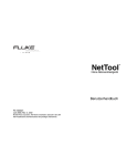
Application Note – DeviceNet configuration SCD-7231-017 Rev. 1.16 How to configure DeviceNet with Anybus NetTool for DeviceNet www.anybus.com HMS Industrial Networks AB Page 1 (29) Application Note – DeviceNet configuration SCD-7231-017 Rev. 1.16 Document history Revision Date Description Responsible 1.00 2006-09-15 Released Thorbjörn Palm 1.01 2006-11-17 Added section in chapter 3.4 Thorbjörn Palm 1.10 2007-08-16 Added section about Ethernet Transport Provider, Anybus Communicator and Xgateway Thorbjörn Palm 1.11 2008-03-05 Minor update Thorbjörn Palm 1.12 2009-06-26 Updated section 3.1 about Driver Selection Martin Falkman 1.13 2009-06-29 Minor corrections after review Martin Falkman 1.14 2009-07-09 and 2009-08-27 Minor corrections from HMS Document Issue Tracking System ID717. Some structural changes. Updated pictures to meet version 3.4.1.3. Lars-Åke Väldesjö 1.15 2009-11-16 Minor updates in chapter 3.1 Martin Falkman 1.16 2011-08-17 Updated picture in chapter 2 to exclude NetTool-DN-D dongle and include direct connection to X-gateway via RS232 and Ethernet. Martin Falkman More information about the network and products The latest manuals, EDS-files and Anybus NetTool for DeviceNet can be found on the HMS homepage, www.anybus.com The DeviceNet user organisation has a homepage on the Internet, www.odva.org. Several technical guides are available in or via this page. www.anybus.com HMS Industrial Networks AB Page 2 (29) Application Note – DeviceNet configuration SCD-7231-017 Rev. 1.16 Contents 1 Applicable Anybus products ........................................................................................................ 4 2 Solution overview ...................................................................................................................... 4 2.1 Hardware Settings ............................................................................................................... 5 3 DeviceNet configuration ............................................................................................................. 6 3.1 Driver Selection - Configuring the Transport Path and go Online ............................................... 6 3.1.1 Anybus NetTool DeviceNet RS232 Interface (dongle) ....................................................... 8 3.1.2 Anybus X-gateway Ethernet via Transport Provider ......................................................... 9 3.1.3 Anybus DEVM PCI-card via Transport Provider .............................................................. 12 3.1.4 Anybus X-gateway (RS232) via Transport Provider ......................................................... 14 3.1.5 EtherNet/IP to DeviceNet Driver .................................................................................. 17 3.2 Online mode .....................................................................................................................18 3.3 Offline mode .....................................................................................................................19 3.4 I/O configuration ...............................................................................................................21 4 Anybus configuration ...............................................................................................................26 4.1 Communicator configuration ..............................................................................................27 4.2 X-gateway configuration .....................................................................................................28 www.anybus.com HMS Industrial Networks AB Page 3 (29) Application Note – DeviceNet configuration SCD-7231-017 Rev. 1.16 1 Applicable Anybus products The following table specifies the relevant Anybus products for this document. Description Name / Type Anybus-M Scanner DeviceNet Scanner/ABM-DEV Anybus-PCI Scanner DeviceNet Scanner/AB-PCI-DEV-M Anybus X-gateway DeviceNet Scanner/ABX-DEVM-xxxx and ABX-DEV-EIP Anybus NetTool-DN-D (RS232 dongle) 018020 Anybus NetTool-DN 018021 USB to RS232 COM-port adapter 019570 2 Version 3.4.1.3 or later Solution overview This document describes how to configure an Anybus DeviceNet Scanner using the Anybus NetTool for DeviceNet. In this case a small example network consisting of two of HMS products has been put together. Below you can find an overview of the network described in this document. Other nodes may be attached to the system, but are not necessary. In this example an Anybus X-gateway DeviceNet Scanner/Modbus RTU adapter interface together with an Anybus Communicator for DeviceNet is used. Example of DeviceNet Adapter Anybus Communicator DeviceNet PC with COM-port (RS232). Optionally using USB to COM-port adapter. Optionally the DeviceNet scanner is configured via Ethernet. RS232 null modem cable Ethernet cable DeviceNet Scanner Anybus X-gateway Other network i.e. Ethernet Ethernet Figure 1 Hardware connection overview. To configure the DeviceNet Scanner module in the X-gateway the program Anybus NetTool for DeviceNet is used. The NetTool-DN-D dongle can be used as a configuration hardware access point for the NetTool for DeviceNet program but the NetTool-DN-D dongle is only required for the embedded Anybus-M module. The contents describe step by step how a configuration is done. This document assumes the reader is familiar with industrial communication, DeviceNet networks and applicable hardware. www.anybus.com HMS Industrial Networks AB Page 4 (29) Application Note – DeviceNet configuration SCD-7231-017 Rev. 1.16 2.1 Hardware Settings Make sure the Mac ID of the adapter and the scanner is not the same. The selected baud rate of the adapter and the scanner is to be set to the same rate. The switches will be found next to the DeviceNet Connector on all the Anybus DeviceNet modules. For further instructions see the Anybus DeviceNet module documentation1. 1 www.anybus.com www.anybus.com HMS Industrial Networks AB Page 5 (29) Application Note – DeviceNet configuration SCD-7231-017 Rev. 1.16 3 DeviceNet configuration To configure the DeviceNet scanner Anybus NetTool for DeviceNet is used. It is possible to configure the network in offline or online mode. It is recommended to start with online mode and to complement with the modules not recognised by the Anybus NetTool for DeviceNet. To begin with, the Transport Path (communication line between program and hardware) has to be configured. 3.1 Driver Selection - Configuring the Transport Path and go Online There are several different ways to connect to the Anybus DeviceNet scanner to be able to download the configuration. Different hardware needs different driver. Anybus NetTool DeviceNet RS232 Interface (dongle) (chapter 3.1.1): This driver is used with the NetToolDN-D RS232 dongle connected to the PC COM-port. The hardware is called Anybus NetTool Config Adapter in the DeviceNet Hardware tree. Anybus Transport Providers (chapter 3.1.2 and 3.1.3): This driver is used with an X-gateway with both an Ethernet module and a DeviceNet scanner module via Ethernet (chapter 3.1.2) or with a PCI-card (chapter 3.1.3). The hardware is called Anybus-M DEV in the DeviceNet Hardware tree (see Figure 2 below, be sure to select the correct revision!). Anybus X-gateway (RS232) (chapter 3.1.4): This driver is used with an X-gateway (DeviceNet Scanner to another Fieldbus network). Connection is done between the RS232 configuration port on the X-gateway to the PC COM-port. The hardware is called Anybus-M DEV in the DeviceNet Hardware tree (see Figure 2 below, be sure to select the correct revision!). EtherNet/IP to DeviceNet Driver (chapter 3.1.5): This driver is only used with the X-gateway EtherNet/IP adapter to DeviceNet scanner (HMS part number AB7607). The hardware is called Anybus X-gateway EIP to DEV in the DeviceNet Hardware tree (see Figure 3 below). Begin with including the DeviceNet scanner hardware at hand in the project; expand the hardware tree to the left and drag-drop the correct hardware item to the right in the network view window. In the example below an Anybus-M DEV is selected (click on the module to be able to configure it). Figure 2 www.anybus.com Dragging in the correct Anybus DeviceNet Master to the right (Anybus-M DEV) HMS Industrial Networks AB Page 6 (29) Application Note – DeviceNet configuration SCD-7231-017 Rev. 1.16 In the example below an Anybus X-gateway EIP to DEV with MAC-ID set to zero is selected (click on the module to be able to configure it). Figure 3 Dragging in the correct Anybus DeviceNet Master to the right (Anybus X-gateway EIP to DEV). Then open the Configure Driver menu from Tools. Figure 4 www.anybus.com Opening the Configure Driver menu. HMS Industrial Networks AB Page 7 (29) Application Note – DeviceNet configuration SCD-7231-017 Rev. 1.16 3.1.1 Anybus NetTool DeviceNet RS232 Interface (dongle) Figure 5 Selecting the type of driver. Step 1: After opening the Configure Driver dialogue choose the Anybus NetTool DeviceNet RS232 Interface driver and press OK. The following dialogue will then appear: Figure 6 Configuring the Serial Transport path. Step 2: Choose your com port, desired DeviceNet baud rate and MacID of the Anybus NetTool-DN-D. Make sure the selected MacID is not identical to another unit in the network. The MacID is 63 by default. Step 3: Then click on Go Online button, question pops up to update network, click OK. Network goes online and network list is updated. Figure 7 www.anybus.com Question to update network. HMS Industrial Networks AB Page 8 (29) Application Note – DeviceNet configuration SCD-7231-017 Rev. 1.16 3.1.2 Anybus X-gateway Ethernet via Transport Provider The driver called Anybus Transport Providers should be used together with X-gateway equipped with an Ethernet interface and an Anybus DeviceNet scanner interface. This driver handles the connection to the DeviceNet scanner via the Ethernet interface on the X-gateway. Note: To be able to use the Ethernet Transport Path the following is required: Install NetTool for DeviceNet version 3.1.1.1 or later on the PC together with the hardware drivers which are included in the installation package (Anybus Transport Provider package). Make sure the X-gateway firmware is version 3.16 or later Step 1: After opening the Configure Driver dialogue, select the Anybus Transport Providers then click OK. Figure 8 Selecting the type of driver. Step 2: Press the Create button in the “Transport Paths” dialog. Figure 9 Creating a new Transport Path. Step 3: Select the Ethernet Transport Provider and click on the Ok button to make a new Transport Path. Give the path a desired name and click OK again. Figure 10 Selecting and naming the new Ethernet Transport Path. www.anybus.com HMS Industrial Networks AB Page 9 (29) Application Note – DeviceNet configuration SCD-7231-017 Rev. 1.16 Step 4: If the IP-address of the gateway is in the same subnet-range as your PC, the gateway will automatically appear in the list shown in the “Ethernet Configuration” dialog. If nothing is showed in the list, proceed to Step 5, else proceed to Step 6. Note: You may need to click the + sign to expand the device tree. The Ethernet interface[X-gateway] needs to be highlighted before pressing Ok. Figure 11 Browsing the IP-address of the connected gateway. Step 5: This step can be skipped if the device appears as desired in the picture above. Use the Anybus IPconfig utility to identify or edit the IP address of the X-gateway (started by pressing the button ). The Anybus module will appear in the list and the IP settings can be modified by doubleclicking the desired IP-address in the list. Click SET to apply the settings. Note that a valid IP-address setting is within the same subnet range as the PC you are using. If your PC has the address 192.168.0.24 and the subnet mask is 255.255.255.0 then the gateway needs to use any free address within 192.168.0.XX. Figure 12 Configuring the IP-address. www.anybus.com HMS Industrial Networks AB Page 10 (29) Application Note – DeviceNet configuration SCD-7231-017 Rev. 1.16 Step 6: The X-gateway with it’s IP address should appear automatically under the Remote Hosts tab, if the IP settings were made correctly. Figure 13 Selecting the connected gateway. A network scan can also be forced by entering the X-gateway IP address in the box to the left of button “Query Host” and then pressing the button. Clicking on the button Remote Hosts. will refresh the list under Step 7: Teh DeviceNet Baudrate and MAC-ID is sat from DIP-Switches. The factory default setting is 500 kbaud and MAC ID 1 with switch setting “1000 0001”. If the network connection is established and goes online, question pops up to update network, click OK. Network goes online and network list is updated. Figure 14 Question to update network. www.anybus.com HMS Industrial Networks AB Page 11 (29) Application Note – DeviceNet configuration SCD-7231-017 Rev. 1.16 3.1.3 Anybus DEVM PCI-card via Transport Provider The driver called Anybus Transport Providers should be used together with a PCI card equipped with an Anybus DeviceNet scanner interface. This driver handles the connection to the DeviceNet scanner on the PCI-card. Note: To be able to use the PCI Transport Path the following is required: Install NetTool for DeviceNet version 3.1.1.1 or later on the PC together with the hardware drivers which are included in the installation package (Anybus Transport Provider package). Step1: After opening the Configure Driver dialogue select the Anybus Transport Providers then click OK. Figure 15 Selecting the type of driver. Step 2: Press the Create button to start creating the new Parallel Transport Path. Figure 16 Creating a new Transport Path Step3: Select the PCI Transport Provider and click on the Ok button to make a new Transport Path. Give the path a desired name and click Ok. Select PCI-card to use and then OK again in the next window. Figure 17 Selecting and naming the new PCI Transport Path. www.anybus.com HMS Industrial Networks AB Page 12 (29) Application Note – DeviceNet configuration SCD-7231-017 Rev. 1.16 Step 4: Select PCI-card to use and then click Ok. Select your path and click Ok. Figure 18 Select PCI-card and new PCI Transport Path. Step 5: Choose your desired DeviceNet baud rate and MacID of the DeviceNet scanner on the PCI-card. Make sure the selected MacID is not identical to another unit in the network. Figure 19 Select Baudrate and MAC-ID. Step 6: Then Click the Go Online button, question pops up to update network, click OK. Network goes online and network list is updated. Figure 20 Question to update network. www.anybus.com HMS Industrial Networks AB Page 13 (29) Application Note – DeviceNet configuration SCD-7231-017 Rev. 1.16 3.1.4 Anybus X-gateway (RS232) via Transport Provider The driver called Anybus X-gateway(RS-232) should be used together with X-gateway equipped with an Anybus DeviceNet scanner interface. This driver handles the connection to the DeviceNet scanner via the Xgateway RS232 configuration port. Note: To be able to use the Serial Transport Path the following is required: Install NetTool for DeviceNet version 3.1.1.1 or later on the PC together with the hardware drivers which are included in the installation package (Anybus Transport Provider package). Make sure the X-gateway firmware is version 3.16 or later Step 1: Opening the Configure Driver dialogue Figure 21 Selecting the type of driver. Step 2: After opening the Configure Driver dialogue choose the Anybus X-gateway (RS-232) and press Ok. The following window will then appear: Figure 22 Configuring the Serial Transport path. Step 3: Open the Serial Tab and click on create. Figure 23 Selecting the Serial Tab. Step 4: Select the COM-port path as shown below and click on the OK button to make a new Transport Path. Give the path a desired name and click OK. www.anybus.com HMS Industrial Networks AB Page 14 (29) Application Note – DeviceNet configuration SCD-7231-017 Rev. 1.16 Figure 24 Selecting and naming the new COM-port Transport Path. Step 5: Select the COM-port, click Ok. After configuring these settings the slot in the X-gateway has to be selected. The upper slot is where the power connection is located. Figure 25 Configuring the Slot and Timeout time. Step 6: If connection to X-gateway via COM-port is established, the DeviceNet Baudrate and MAC ID has to be configured the same as on the DIP-Switches. The factory default setting is 500 kbaud and MAC ID 1 with switch setting “1000 0001”. Figure 26 Configuring the Baudrate and MAC ID. Step 7: If the network connection is established and goes online, question pops up to update network, click OK. Network goes online and network list is updated. Figure 27 Question to update network. If the error-box below appears try again from Step 1 with created Transport path. Figure 28 Error-box when trying to set network parameters. www.anybus.com HMS Industrial Networks AB Page 15 (29) Application Note – DeviceNet configuration SCD-7231-017 Rev. 1.16 If the error-box below appears, check bus-cable and bus-power and try again from Step 1 with created Transport path. Figure 29 Error-box when trying to connect. www.anybus.com HMS Industrial Networks AB Page 16 (29) Application Note – DeviceNet configuration SCD-7231-017 Rev. 1.16 3.1.5 EtherNet/IP to DeviceNet Driver The driver called EtherNet/IP to DeviceNet Driver should be used together with the product X-gateway EtherNet/IP adapter to DeviceNet scanner (e.g. HMS part number AB7607). This driver handles the DeviceNet scanner connection via EtherNet/IP only. Step 1: After opening the Configure Driver dialogue choose EtherNet/IP to DeviceNet Driver in the Driver Dialog and press Ok. Figure 30 Selecting the type of driver. Step 2: The Browse for network window will appear like the window below if the X-gateway is properly connected to the EtherNet/IP network. Click the + sign to expand the Ethernet to DeviceNet Gateway entry. Then highlight the entry below and click the OK button. Figure 31 Selecting the module to configure. Step 3: If the network connection is established and goes online, question pops up to update network, click OK. Network goes online and network list is updated. Figure 32 Question to update network. www.anybus.com HMS Industrial Networks AB Page 17 (29) Application Note – DeviceNet configuration SCD-7231-017 Rev. 1.16 3.2 Online mode After connection is made as above NetTool is Online. Else press Go Online Online button Figure 33 The online button. To upload the current configuration, update your network as shown below. Figure 34 The update window. In this example the following network will appear: Figure 35 Online network. www.anybus.com HMS Industrial Networks AB Page 18 (29) Application Note – DeviceNet configuration SCD-7231-017 Rev. 1.16 3.3 Offline mode For devices not included in the library of the NetTool for DeviceNet an EDS file has to be imported. If the module is not included in the library the unit will not be recognised by the program. The EDS file is to be provided by the manufacturer of the module. In this case the EDS file for the Anybus Communicator and X-gateway can be downloaded at HMS website1. Make sure the program is in offline mode. Offline mode Figure 36 The offline mode. Press the EDS file button and click on Next button. Figure 37 Install EDS file dialogue. Locate your EDS file, press OK and then press Finish. 1 www.anybus.com www.anybus.com HMS Industrial Networks AB Page 19 (29) Application Note – DeviceNet configuration SCD-7231-017 Rev. 1.16 Figure 38 Installing EDS file. The module will now be seen in the library. Figure 39 The NetTool library. By using drag and drop it is possible to set up the current network. When the network is completed press the Go Online button. If the settings are correct none of the selected modules will be red marked. Figure 40 The online network. Figure 41 AnyBus-M in configuration is not found as node address 3. www.anybus.com HMS Industrial Networks AB Page 20 (29) Application Note – DeviceNet configuration SCD-7231-017 Rev. 1.16 3.4 I/O configuration The next step is to configure the amount of I/O data. First the number of bytes to/from the nodes in the network has to be concluded. The second step is to configure the scanner module. Start with double click the Anybus-C DeviceNet icon in the network and press Yes in the appearing dialogue. Figure 42 Upload of the parameters. The window below will then appear. Figure 43 I/O configuration of the adapter module, in this case the communicator. In this case the number off input bytes is 18. www.anybus.com HMS Industrial Networks AB Page 21 (29) Application Note – DeviceNet configuration SCD-7231-017 Rev. 1.16 Configuring the scanner module The next step is to configure the scanner module. Double click on the Anybus-M module and press Yes to upload parameters in the same way as previously. Open the scanner tile and press Yes in the following dialogue to upload the scan list as shown below. Figure 44 The scan list. Mark the Anybus-C DeviceNet and click Add to move the module to the right list. Figure 45 Configuring the scanner. www.anybus.com HMS Industrial Networks AB Page 22 (29) Application Note – DeviceNet configuration SCD-7231-017 Rev. 1.16 The window shown below will be seen (later found by selecting the Anybus-C DeviceNet icon and pushing the Edit Slave button). The window shown below will be seen. Figure 46 Configuring the I/O data of the scanner module. In this case the alternative Polled is selected and 18 bytes Rx (in) and Tx (out) is chosen. The number of bytes and method of communication is depending on the characteristics of the adapter modules in the network. In this case the 18 bytes will match the I/O data size of the Anybus Communicator module. Press OK and select the Input tile. Figure 47 Configuring the Input data. www.anybus.com HMS Industrial Networks AB Page 23 (29) Application Note – DeviceNet configuration SCD-7231-017 Rev. 1.16 The Anybus-C module is Automapped. This mode is used when no manual mapping is required. When the Automap button is pressed the I/O will be mapped from the first free position after Word Offset + Bit Offset where all the data can be mapped in one chunk. In the same way the output data can be configured. First Master state has to be sat to Idle. Open the tile Parameter, make sure the master is in idle state and press the Download button as shown below. Figure 48 Downloading Parameters to the scanner. Then the scanlist has to be downloaded to the scanner. Open the tile Scanlist again and press the Download scanlist button as shown below. Figure 49 Downloading the Scanlist to the scanner. www.anybus.com HMS Industrial Networks AB Page 24 (29) Application Note – DeviceNet configuration SCD-7231-017 Rev. 1.16 The next and final step is to open the diagnostics tab. Press the Update button and if the configuration is correct no faults will appear. Figure 50 Diagnostics window. www.anybus.com HMS Industrial Networks AB Page 25 (29) Application Note – DeviceNet configuration SCD-7231-017 Rev. 1.16 4 Anybus configuration The Anybus product has to be configured for the same I/O sizes as set up in the DeviceNet scanner configuration. Note: The I/O sizes are depending on the application, the configured I/O sizes in this chapter are just examples. Anybus-M Scanner and the Anybus-PCI card The Anybus Master Interface and the Anybus PCI card are configured by mailbox commands. Refer to respective Fieldbus Appendix for details. Anybus Communicator The configuration of the Anybus Communicator is described in section 4.1 below. Anybus X-gateway The configuration of the Anybus X-gateway is described in section 4.2 below. www.anybus.com HMS Industrial Networks AB Page 26 (29) Application Note – DeviceNet configuration SCD-7231-017 Rev. 1.16 4.1 Communicator configuration To configure the Communicator, start the ABC Config Tool, select the fieldbus DeviceNet and the desired I/O data. If explicit data is used the I/O sizes has to be set to user defined mode, otherwise automatic can be used. For a more detailed description see the Communicator User Manual. Figure 51 Configuring the Communicator www.anybus.com HMS Industrial Networks AB Page 27 (29) Application Note – DeviceNet configuration SCD-7231-017 Rev. 1.16 4.2 X-gateway configuration Use the HyperTerminal on a PC and configure the X-gateway, connect a serial cable between the PC and the config port on the X-gateway. Open the “File” menu and click on new, choose the desired COM port and click OK. The following window will appear. Figure 52 Configuring the connection in the HyperTerminal. Make sure the settings are identical to those shown in the window above. An alternative method is to download the HyperTerminal session file from HMS website, double click on it and select COM port. www.anybus.com HMS Industrial Networks AB Page 28 (29) Application Note – DeviceNet configuration SCD-7231-017 Rev. 1.16 Connect and press ESC and the following menu will appear. Figure 53 Anybus X-gateway Main menu. Press 6 and enter the desired configuration. The figure below shows an example; in this case a DeviceNet Scanner/PROFINET IO Adapter X-gateway is used and 20 bytes of I/O data is configured. Figure 54 The X-gateway configuration. Note: The default setting in the X-gateway is that it will reboot every time the on-line connection over Ethernet is broken. This setting can be changed at last roe in the X-gateway configuration above. Press ESC, Press 6 to enter the “Change configuration” dialog. Press Enter until you get to the “Reboot after disconnection” parameter and then change this setting to “Disabled”. Press Enter and answer Yes to the following questions. The gateway will now continue to run without interruption after an online session in NetTool DeviceNet. www.anybus.com HMS Industrial Networks AB Page 29 (29)