1
GE Fanuc Automation
Programmable Control Products
Using PC Control Software
GFK-1424B
August 1998
GFL-002
Warnings, Cautions, and Notes
as Used in this Publication
Warning
Warning notices are used in this publication to emphasize that hazardous
voltages, currents, temperatures, or other conditions that could cause
personal injury exist in this equipment or may be associated with its use.
In situations where inattention could cause either personal injury or
damage to equipment, a Warning notice is used.
Caution
Caution notices are used where equipment might be damaged if care is not
taken.
Note
Notes merely call attention to information that is especially significant to
understanding and operating the equipment.
This document is based on information available at the time of its publication. While efforts have
been made to be accurate, the information contained herein does not purport to cover all details or
variations in hardware or software, nor to provide for every possible contingency in connection
with installation, operation, or maintenance. Features may be described herein which are not
present in all hardware and software systems. GE Fanuc Automation assumes no obligation of
notice to holders of this document with respect to changes subsequently made.
GE Fanuc Automation makes no representation or warranty, expressed, implied, or statutory with
respect to, and assumes no responsibility for the accuracy, completeness, sufficiency, or usefulness
of the information contained herein. No warranties of merchantability or fitness for purpose shall
apply.
The following are trademarks of GE Fanuc Automation North America, Inc.
Alarm Master
CIMPLICITY
CIMPLICITY PowerTRAC
CIMPLICITY 90–ADS
CIMSTAR
Field Control
GEnet
Genius
Genius PowerTRAC
Helpmate
Logicmaster
Modelmaster
PowerMotion
ProLoop
PROMACRO
Series Five
Series 90
Series One
Series Six
Series Three
VuMaster
Workmaster
©Copyright 1997—1998 GE Fanuc Automation North America, Inc.
All Rights Reserved.
Preface
Revisions to This Manual
Release 2.0 of PC Control software provides the following new features:
Runtime error reporting — page 2-5
Cryp Key emergency authorization — page 2-14
Smart Shutdown UPS monitor — pages 2-19 and 2-30
New System Option dialogue window — page 2-26
Structure and Function Block Enumeration — page 2-29
IEC reference display — page 2-29
Import/Export of symbols via a .CSV file for Global Symbols, and GE Fanuc
PCIM and PCIM variables — page 3-41
Enhanced parser error handling — page 4-102
Seamless online editing — page 4-115
Structured Text and Instruction List programming languages for standalone
programs — Sections 4 and 5 in Chapter 4
Menu driven Structured Text Editor — Section 4 in Chapter 4
ActiveX interface — page 6-33
PCIF2 driver support for Series 90-30 I/O interface — Appendix C
APM and DSM configuration; Program 0 creation and download — page E-2
and the online help for configuring your motion control card
Motion Control programming and operator interface controls — Appendix E
Support for Indirect addressing (Pointers) — appendix F
Change MMI function — “Miscellaneous Functions” in Appendix G
Additional timer types — “Extended Timers” in Appendix G
New instructions for conversions and extended timers — Appendix G
Support of user defined C function blocks — refer to application note
APP981R1 provided on the PC Control CD for details on using the CFB Editor
GFK-1424B
iii
Preface
Content of This Manual
Chapter 1.
Introduction: Provides the requirements and procedures for
installing PC Control on your computer and tells how to use online documentation.
Chapter 2.
Getting Started: Provides an overview of PC Control operation and
the main tasks you need to perform to create a control application. Describes how to
create a new project to hold all of the associated files.
Chapter 3.
Configuring I/O: Describes how to configure GENIUS® I/O and
Series 90-30 I/O within PC Control software.
Chapter 4.
Creating Application Programs: Describes how to create Sequential
Function Chart, Relay Ladder Logic, Structured Text, and Instruction List programs.
Chapter 5.
Running Application Programs: Describes how to start the run-time
systems and run an application program.
Chapter 6.
Creating Operator Interface Applications: Describes how to create
an operator interface screen using the integrated PC Control GUI editor.
Appendix A.
The Personal Computer Interface Module (PCIM) for Genius I/O:
This appendix describes how to install the PCIM in your personal computer and
configure the module using the PCIM Configuration Utility in the PC Control
software.
Appendix B.
The Personal Computer Interface (PCIF) for Series 90-30 I/O: This
appendix describes how to install the PCIF in your personal computer.
Appendix C.
The Personal Computer Interface (PCIF2) for Series 90-30 I/O:
This appendix describes how to install the PCIF2 in your personal computer.
Appendix D.
Application Example: Provides step-by-step instructions on how to
create an application program using the SFC and Relay Ladder program editors. An
Operator Interface screen is also constructed to monitor and control program
operation.
Appendix E.
Motion Control: Describes how to use the RS-274D compliant
language set of text-based instructions for motion control operation.
Appendix F.
Pointers: (For advanced users) Describes how to use pointers for
indirect addressing operations in Structured Text.
iv
Appendix G.
Instruction Set Reference
Appendix H.
Glossary of Terms
Using PC Control Software –August 1998
GFK-1424B
Preface
Related Publications
GEK-90486-1
Genius® I/O System User's Manual
GFK-0898
Series 90™-30 Programmable Controller I/O Module
Specifications
GFK-0826
Field Control Distributed I/O and Control System User's Manual
GFK-0356
Series 90™-30 Programmable Controller Installation Manual
GFK-1180
CIMPLICITY® HMI for Window NT® and Windows® 95 Base
System User’s Manual
At GE Fanuc Automation, we strive to produce quality technical documentation.
After you have used this manual, please take a few moments to complete and return
the Reader's Comment Card located on the next page.
Libby Allen
Senior Technical Writer
GFK-1424B
Preface
v
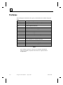
Contents
Chapter 1
Introduction...................................................................................... 1-1
Section 1: Setting Up PC Control .................................................. 1-2
Before You Begin .............................................................................. 1-2
Upgrading PC Control ....................................................................... 1-4
Installing PC Control Software .......................................................... 1-4
Running and Authorizing PC Control Software ................................ 1-5
Section 2: Using Online Documentation ....................................... 1-7
Online Help........................................................................................ 1-7
Chapter 2
Getting Started ................................................................................. 2-1
Section 1: Overview of the Software ............................................ 2-2
Software Subsystems ......................................................................... 2-2
IEC 1131 Overview ........................................................................... 2-3
IEC 1131-3 Programming Languages ...................................................................... 2-3
Quick Start ......................................................................................... 2-4
PC Control Runtime Subsystems ............................................................................. 2-6
Program Editor......................................................................................................... 2-7
Access Levels........................................................................................................... 2-7
Keyboard Shortcuts for the Operator Interface ........................................................ 2-9
Menu Descriptions ................................................................................................. 2-10
Toolbars and Status Bar ......................................................................................... 2-16
Answers to Common Questions ............................................................................. 2-18
Section 2: Working with Projects and Applications................ 2-20
Managing Projects............................................................................ 2-20
Creating a New Project .......................................................................................... 2-20
Opening a Project................................................................................................... 2-20
Copying a Project................................................................................................... 2-21
Renaming a Project ................................................................................................ 2-21
Activating a Configuration..................................................................................... 2-21
Working With Application Programs .............................................. 2-22
Creating a New Program........................................................................................ 2-22
Opening a Program ................................................................................................ 2-22
Saving a File .......................................................................................................... 2-23
Printing a Program ................................................................................................. 2-23
Printing Program Cross-References ....................................................................... 2-24
GFK-1424B
vii
Contents
Managing Application Programs ........................................................................... 2-24
Closing Application Programs ............................................................................... 2-24
Viewing Programs.................................................................................................. 2-25
Sizing a Program to Fit the Window ...................................................................... 2-25
Turning Comments On and Off.............................................................................. 2-25
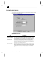
Setting System Options.................................................................... 2-26
IEC Style Locations ......................................................................... 2-29
UPS Configuration........................................................................... 2-30
Section 3: Program Operation Overview.................................. 2-32
Activate Configuration..................................................................... 2-32
First Scan with Active Configuration .............................................. 2-32
Power-down Sequence..................................................................... 2-32
Normal Operation ............................................................................ 2-33
File Names ....................................................................................... 2-34
Chapter 3
Configuring I/O................................................................................ 3-1
Section 1: Overview ...................................................................... 3-2
Help With Hardware Conflicts .......................................................... 3-2
Data I/O Port............................................................................................................ 3-3
Memory Address...................................................................................................... 3-3
Interrupt – IRQ......................................................................................................... 3-3
Working with Configuration Files ..................................................... 3-4
Elements of a Configuration .................................................................................... 3-4
Creating a New Configuration ................................................................................. 3-4
Editing an Existing Configuration File..................................................................... 3-4
Activating a Configuration File................................................................................ 3-4
Navigating Within the Configuration Utility ..................................... 3-5
About the System Configuration Dialog Box........................................................... 3-5
I/O Scan Rate ........................................................................................................... 3-5
Using the Define Board Dialog Box ........................................................................ 3-6
Section 2: Configuring GENIUS I/O............................................ 3-7
The PC Interface Module (PCIM)...................................................... 3-7
Global Data Setup Dialog Box............................................................................... 3-11
Global Data: Device............................................................................................... 3-11
Global Data: Device, Word.................................................................................... 3-11
viii
Using PC Control Software –August 1998
GFK-1424B
Contents
Genius Bus Address Definitions...................................................... 3-11
Using the Genius Bus Address Definitions Dialog Box......................................... 3-12
Discrete Point Information..................................................................................... 3-13
Sending Datagrams with the PCIM Driver............................................................. 3-15
Section 3: Configuring Series 90-30 I/O .................................... 3-16
The PC Interface (PCIF) .................................................................. 3-16
Using the PCIF Board Dialog .......................................................... 3-16
The Rack Definition Dialog............................................................. 3-18
The Module Dialog .......................................................................... 3-18
Defining Digital Port Connections ......................................................................... 3-19
Defining Analog Port Connections ........................................................................ 3-19
Section 4: Configuring Other Field Busses................................ 3-20
Configuring DeviceNet I/O.............................................................. 3-20
Capabilities ............................................................................................................ 3-20
Installing and Configuring Devices on the DeviceNet Network ............................ 3-20
Configuring Profibus I/O ................................................................. 3-22
Section 5: Dynamic Data Exchange............................................ 3-38
About the DDE Interface ................................................................. 3-38
DDE Communication with Microsoft's Excel Software.................. 3-38
Transferring Data to Excel..................................................................................... 3-38
Transferring Data to the Control System................................................................ 3-39
Transferring Values to the Control System Upon Request..................................... 3-39
Section 6: Import/Export Configuration ................................... 3-41
Chapter 4
Creating Application Programs...................................................... 4-1
Section 1: Configuring Symbols ................................................... 4-2
About Symbols................................................................................... 4-2
Symbol Scope .................................................................................... 4-2
Identifiers ........................................................................................... 4-3
Literals ............................................................................................... 4-4
Numeric Literals ...................................................................................................... 4-4
Character String Literals .......................................................................................... 4-4
Time Duration Literals............................................................................................. 4-5
Time of Day and Date Literals................................................................................. 4-6
Data Types ......................................................................................... 4-7
GFK-1424B
Contents
ix
Contents
BOOL (Boolean)...................................................................................................... 4-7
BYTE....................................................................................................................... 4-7
DATE....................................................................................................................... 4-8
DINT (Double Integer) ............................................................................................ 4-8
DWORD (Double WORD)...................................................................................... 4-8
INT (Integer)............................................................................................................ 4-8
REAL ....................................................................................................................... 4-9
STRING................................................................................................................... 4-9
TIME ....................................................................................................................... 4-9
TOD (TIME_OF_DAY) ........................................................................................ 4-10
UINT (Unsigned Integer)....................................................................................... 4-10
WORD ................................................................................................................... 4-10
Generic Data Types.......................................................................... 4-11
User-Defined Data Type .................................................................. 4-11
Arrays............................................................................................... 4-12
Pointer Symbols ............................................................................... 4-12
Symbol Manager .............................................................................. 4-12
Opening the Symbol Manager................................................................................ 4-12
Creating a Symbol.................................................................................................. 4-14
Editing a Symbol.................................................................................................... 4-14
Copying a Symbol.................................................................................................. 4-16
Deleting a Symbol.................................................................................................. 4-16
Naming a Bit in a Symbol ...................................................................................... 4-16
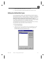
Editing User-Defined Data Types.................................................... 4-17
Using Symbols ................................................................................. 4-19
Drag-and-Drop....................................................................................................... 4-19
Enumerations ......................................................................................................... 4-19
System Symbols............................................................................... 4-20
Predefined System Symbols................................................................................... 4-20
Run-Time Symbols ................................................................................................ 4-21
Keywords ............................................................................................................... 4-22
Exporting Symbols for CIMPLICITY HMI........................................................... 4-25
Section 2: RLL Programming...................................................... 4-26
Overview of Relay Ladder Logic Diagrams .................................... 4-26
How RLL Application Programs are Solved ................................... 4-27
How Simple Relay Logic is Solved........................................................................ 4-27
How RLL Logic is Solved When Function Blocks Are Used ................................ 4-28
x
Using PC Control Software –August 1998
GFK-1424B
Contents
Creating a Relay Ladder Logic Program.......................................... 4-28
Section 3: SFC Programming ..................................................... 4-41
Overview of Sequential Function Charts ......................................... 4-41
About Steps............................................................................................................ 4-41
Using the Step System Symbols............................................................................. 4-43
About Actions ........................................................................................................ 4-44
Action Manager ..................................................................................................... 4-50
About Transitions................................................................................................... 4-50
About Divergences................................................................................................. 4-51
About Program Flow Control Features .................................................................. 4-53
How SFCs are Solved ............................................................................................ 4-56
How Transitions are Evaluated .............................................................................. 4-57
Using Simultaneous Divergences........................................................................... 4-58
Using Macro Steps................................................................................................. 4-58
Extensions to IEC 1131-3 ...................................................................................... 4-59
Creating Sequential Function Charts ............................................... 4-60
Creating an SFC Program ...................................................................................... 4-60
Using the SFC Tool and Menu Bar........................................................................ 4-62
Working with Steps................................................................................................ 4-63
Working with Transitions ...................................................................................... 4-66
Working with Macro Steps .................................................................................... 4-67
Working with Actions ............................................................................................ 4-68
Adding SFC Program Flow Controls ..................................................................... 4-71
Integrating Structured Text into an SFC ................................................................ 4-80
Documenting an SFC Program............................................................................... 4-81
Section 4: Structured Text Programming.................................. 4-82
Overview.......................................................................................... 4-82
Opening a Structured Text Document.................................................................... 4-82
Editing Structured Text in an SFC Step ................................................................. 4-82
Entering Statements ............................................................................................... 4-83
Editing Structured Text.......................................................................................... 4-83
Language Overview ......................................................................... 4-84
Expressions ............................................................................................................ 4-84
Operators................................................................................................................ 4-84
Pointer Operators ................................................................................................... 4-85
Structured Text Syntax........................................................................................... 4-85
Assignment Statement............................................................................................ 4-86
GFK-1424B
Contents
xi
Contents
BREAK Statement ................................................................................................. 4-87
CASE Statement .................................................................................................... 4-87
Comments .............................................................................................................. 4-88
Exit Statement ........................................................................................................ 4-89
IF Statement ........................................................................................................... 4-90
INCLUDE.............................................................................................................. 4-91
FOR Statement....................................................................................................... 4-91
Function Call.......................................................................................................... 4-93
LABEL................................................................................................................... 4-93
REPEAT Statement................................................................................................ 4-94
SCAN..................................................................................................................... 4-95
WHILE Statement.................................................................................................. 4-95
Structured Text Operators...................................................................................... 4-97
About the Statement Types .................................................................................... 4-98
Using PIDs in an Application Program.................................................................. 4-98
Controlling the Flow of RLL and Structured Text Application Programs ........... 4-100
Monitoring and Testing Application Programs and Symbols .............................. 4-102
Section 5: Instruction List Programming ................................ 4-105
Overview........................................................................................ 4-105
Opening an Instruction List Document ................................................................ 4-105
Entering Instructions ............................................................................................ 4-105
Editing Instructions .............................................................................................. 4-106
Language Overview ....................................................................... 4-107
Instruction List Syntax ......................................................................................... 4-107
Operators.............................................................................................................. 4-108
Functions and Function Blocks ............................................................................ 4-110
Program Examples ......................................................................... 4-112
General Operations Example ............................................................................... 4-113
Call to Function Block Example .......................................................................... 4-114
Section 6: Online Editing ........................................................... 4-115
Online Editing Operation............................................................... 4-115
Rules .............................................................................................. 4-116
General................................................................................................................. 4-116
Symbols................................................................................................................ 4-116
I/O ........................................................................................................................ 4-116
RLL Programs...................................................................................................... 4-117
SFC Programs ...................................................................................................... 4-117
xii
Using PC Control Software –August 1998
GFK-1424B
Contents
File Operations..................................................................................................... 4-117
Structured Text Programs .................................................................................... 4-118
Instruction List Programs..................................................................................... 4-118
Chapter 5
Running Application Programs...................................................... 5-1
Runtime Subsystems.......................................................................... 5-2
Running an Individual Program ............................................................................... 5-2
Running the Active Program.................................................................................... 5-2
Canceling a Running Program ................................................................................. 5-3
Configuring Programs to Execute Automatically .............................. 5-4
Starting Programs with a Batch file ......................................................................... 5-4
Starting Programs with the Run With Restart Command ......................................... 5-5
Monitoring Power Flow..................................................................... 5-5
Active RLL Programs .............................................................................................. 5-5
Active SFC Programs............................................................................................... 5-5
Viewing the Status of Application Programs..................................... 5-6
Chapter 6
Creating Operator Interface Applications .................................... 6-1
Section 1: Overview of the Operator Interface Editor ............... 6-2
Starting the Operator Interface........................................................... 6-2
Access Levels..................................................................................... 6-2
Entering an Access Code ......................................................................................... 6-3
Changing Access Levels .......................................................................................... 6-3
Activation and Edit Modes ................................................................ 6-4
Switching Operator Interface Modes ................................................. 6-4
Controlling RLL Programs from an Operator Interface..................... 6-5
Section 2: Working with Operator Interface Screens ................ 6-6
Operator Interface Operations............................................................ 6-6
Starting a New Operator Interface File .................................................................... 6-6
Opening an Operator Interface File.......................................................................... 6-6
Saving an Operator Interface File ............................................................................ 6-6
Screen Operations .............................................................................. 6-7
Creating a New Operator Interface Screen............................................................... 6-7
Deleting a Screen ..................................................................................................... 6-7
Copying a Screen ..................................................................................................... 6-7
Renaming a Screen................................................................................................... 6-8
GFK-1424B
Contents
xiii
Contents
Selecting the Startup Screen..................................................................................... 6-8
Selecting a Screen to Edit ........................................................................................ 6-8
Section 3: Working with Controls ................................................ 6-9
Adding Controls................................................................................. 6-9
Editing Controls ................................................................................. 6-9
Selecting Controls............................................................................ 6-10
Moving Controls .............................................................................. 6-10
Sizing Controls ................................................................................ 6-11
Copying, Cutting, and Pasting ......................................................... 6-11
Deleting Controls ............................................................................. 6-12
Aligning Controls............................................................................. 6-12
Moving Controls Front/Back ........................................................... 6-12
Section 4: Symbol Operations..................................................... 6-13
Editing Symbols............................................................................... 6-13
Activating Configurations................................................................ 6-13
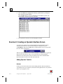
Section 5: Creating Operator Interface Applications............... 6-14
Standard Controls............................................................................. 6-14
Introduction............................................................................................................ 6-14
Bar ......................................................................................................................... 6-16
Bitmap.................................................................................................................... 6-18
Box......................................................................................................................... 6-19
Click Button ........................................................................................................... 6-20
Continuous Button ................................................................................................. 6-23
Gauge ..................................................................................................................... 6-25
Indicator................................................................................................................. 6-27
Numeric Display .................................................................................................... 6-29
Selected Program Status Panel............................................................................... 6-30
Slide ....................................................................................................................... 6-30
Text ........................................................................................................................ 6-32
ActiveX Controls ............................................................................. 6-33
Introduction............................................................................................................ 6-33
ActiveX Limitations............................................................................................... 6-33
ActiveX and Standard Controls ............................................................................. 6-34
ActiveX Control Sources ....................................................................................... 6-34
Registering ActiveX Controls ................................................................................ 6-35
xiv
Using PC Control Software –August 1998
GFK-1424B
Contents
Inserting ActiveX Controls .................................................................................... 6-36
Editing ActiveX Controls....................................................................................... 6-37
Appendix A The Personal Computer Interface Module for Genius I/O ......... A-1
Description.............................................................................................................. A-1
Installation and Configuration................................................................................. A-3
Connecting the PCIM to the Bus........................................................................... A-12
Removing the PCIM from the Bus........................................................................ A-13
Specifications........................................................................................................ A-14
PCIM Electrical Characteristics............................................................................ A-15
Troubleshooting .................................................................................................... A-16
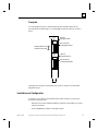
Appendix B Personal Computer Interface (PCIF) for Series 90-30 I/O ..........B-1
Installing the PCIF-30..............................................................................................B-1
Configuring the PCIF-30 Card.................................................................................B-4
Appendix C Personal Computer Interface (PCIF2) for Series 90-30 I/O ....... C-1
Overview............................................................................................C-1
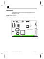
Compatibility .....................................................................................C-2
Hardware Overview ...........................................................................C-2
Jumpers ....................................................................................................................C-3
Connectors ...............................................................................................................C-4
DIP Switch ...............................................................................................................C-6
Quick Start Guide ..............................................................................C-7
Appendix D Application Examples..................................................................... D-1
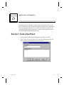
Exercise 1: Create a New Project...................................................... D-1
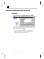
Exercise 2: Create a New System Configuration.............................. D-2
Exercise 3: Creating an SFC ............................................................. D-5
Exercise 4: Creating Symbols ........................................................... D-9
Exercise 5: Adding Transition Logic .............................................. D-11
Exercise 6: Entering Structured Text Commands........................... D-13
Exercise 7: Adding and Editing Action Blocks .............................. D-14
Exercise 8: Executing the Sample Program.................................... D-19
Exercise 9: Creating an Operator Interface Screen ......................... D-20
GFK-1424B
Contents
xv
Contents
Appendix E Motion Control.................................................................................E-1
Configuring Motion Control ..............................................................E-2
Motion Control Programming............................................................E-3
Adding Motion Control to an SFC...........................................................................E-3
PC CONTROL Software Enhancements to RS-274D..............................................E-3
Using Motion Control Statements............................................................................E-4
Using Predefined Motion Control Symbols ...........................................................E-11
Configuring Motion Options..................................................................................E-18
Using Program Flow Control in Motion Applications ...........................................E-19
Using the G56 Macro Calls with Motion ...............................................................E-22
Monitoring and Running Motion Application Programs........................................E-24
Embedding Structured Text into Motion Control Code .........................................E-27
Structured Text Motion Functions .........................................................................E-29
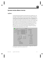
Operator Interface Motion Controls.................................................E-31
Jog Panel................................................................................................................E-31
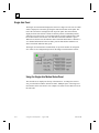
Single Axis Panel ...................................................................................................E-32
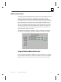
Multi-Axis Status Panel .........................................................................................E-33
RS274 Block Display.............................................................................................E-34
Appendix F Pointers in Structured Text.............................................................F-1
Addressing ......................................................................................... F-2
Pointer Operators ............................................................................... F-2
Pointer Symbol Definition ................................................................. F-3
Pointer Notes............................................................................................................ F-3
Array Pointers .................................................................................... F-5
Appendix G Instruction Set Reference ............................................................... G-1
RLL Instruction Set Summary .......................................................... G-1
SFC Instruction Set Summary........................................................... G-7
Structured Text Instruction Set Summary....................................... G-10
Instruction List Instruction Set Summary ....................................... G-17
Appendix H Glossary of Terms ........................................................................... H-1
xvi
Using PC Control Software –August 1998
GFK-1424B
Chapter
Introduction
1
Welcome to PC Control, GE Fanuc's new software package that provides an
integrated programming, configuration, operator graphical user interface (GUI), and
run-time package that runs under the Windows NT® 4.0 environment. PC Control
software provides support for connecting to Genius®, Field Control™, DeviceNet™,
PROFIBUS, and Series 90™-30 I/O.
With PC Control software, you can:
•
Create an application project
•
Configure your I/O hardware
•
Create and edit symbols
•
Create and edit an application program
•
Run the program under Windows NT
This chapter provides the following information:
•
Requirements and procedures for installing PC Control software on your
computer
•
Guidelines for running PC Control software under Windows® 95
•
How to use the product’s Online Help
Windows NT and Windows® 95 are registered trademarks of Microsoft Corporation.
DeviceNet is a trademark of the Open DeviceNet Vendor Association, Inc.
GFK-1424B
1-1
1
Section 1: Setting Up PC Control
This section provides the recommended system requirements for running PC Control
on your computer and tells how to install the program.
Before You Begin
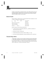
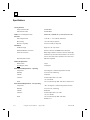
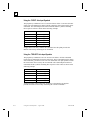
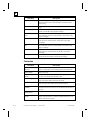
Running Under Windows NT
Your system must meet the following minimum requirements to successfully install
and run PC Control for Windows NT.
Windows NT 4.0 requires Service Pack 3.
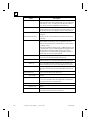
CPU
RAM
Hard Drive
CD-ROM Drive
Monitor
Keyboard and
Pointing Device
UPS System
Recommended
Pentium, 100MHz
32 MB (64 MB preferred)
100 MB free
Yes
VGA minimum
SVGA recommended
Yes
Recommended
Appropriate I/O interfaces are required. Additional resources may be required to
support other applications which will run concurrently.
You should also check the Important Product Information document shipped with
your release for any last minute changes to these requirements.
1-2
Using PC Control Software – August 1998
GFK-1424B
1
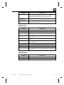
Running Under Windows 95
Warning
Windows 95 is not a protected-mode operating system. We do
not recommend controlling any process with PC Control
software running under Windows 95. The Windows 95
operating system should be used for program development
only.
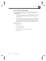
PC Control supports offline development and demo operation under Windows 95,
with I/O in simulation mode. Your system must meet the following minimum
requirements to run PC Control under Windows 95.
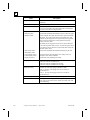
CPU
RAM
Hard Drive
CD-ROM Drive
Monitor
Keyboard and
Pointing Device
UPS System
Recommended
Pentium, 100MHz
32 MB (64 MB preferred)
100 MB free
Yes
VGA minimum
SVGA recommended
Yes
Recommended
You should also check the Important Product Information document shipped with
your release for any last minute changes to these requirements.
GFK-1424B
Chapter 1 Introduction
1-3
1
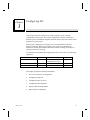
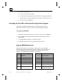
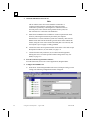
Upgrading PC Control
If you are upgrading an authorized version of PC Control, perform these steps before
installing Version 2.0.
1.
From the Control Panel, double click Add/Remove Programs.
2.
Click the Install/Uninstall tab.
3.
Highlight PC Control and click the Add/Remove button.
4.
Click Yes to remove previous versions.
5.
Using Explorer, delete the BIN folder in the path \PCCONTROL\BIN
6.
Follow instructions for Installing and Authorizing PC Control Software.
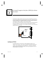
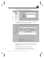
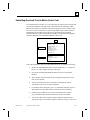
Installing PC Control Software
Before you begin, check the Important Product Information document shipped with
your release for any last minute changes or special operation notes about the
installation procedure.
The installation instructions given here assume that the CD-ROM drive is d:. If you
have assigned another drive to the CD-ROM, make the appropriate substitutions in
these instructions.
You can quit or exit installation anytime during the process. To install PC Control for
Windows NT software:
1-4
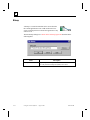
1.
Place the CD-ROM in the CD-ROM drive. Setup is invoked automatically.
Double-click the icon beside Setup.exe. The PC Control Setup screen will
appear.
2.
Read the introduction. Click Next to continue with the install procedure.
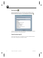
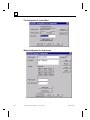
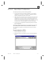
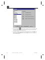
3.
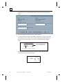
The Select Destination Directory dialog box will appear. The default directory is
C:\CIMPLICITY\PCCONTROL. To change the default directory, click the
Browse button and select an alternate directory. To accept the directory, click
Next.
4.
The PC Control files will be installed in the destination directory. This process
can take several minutes to complete.
Using PC Control Software – August 1998
GFK-1424B
1
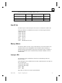
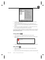
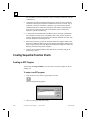
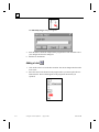
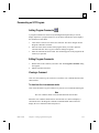
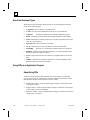
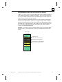
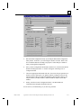
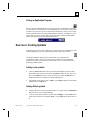
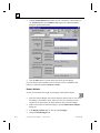
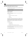
Running and Authorizing PC Control Software
After installing PC Control, you can run the software in Demo mode or you can
register the software to operate in Authorized mode. Demo mode is restricted to 32
I/O points and 2 hours of operation..
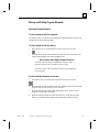
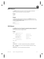
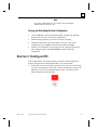
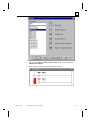
To run PC Control in Demo mode:
1.
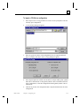
Locate the Control Program Editor icon from Programs, as shown:
The Key Validation dialog box appears.
2.
Click the Demo button. The License Information dialog box will appear.
3.
Read the agreement and click the I Agree button to accept and continue. The
Enter Password dialog box appears.
4.
Enter the default password 4, 5, 6, 7 and click the Enter button.
PC Control is now running in Demo mode.
To run PC Control in Authorized mode:
You can run only purchased software in authorized mode. Demo CDs will not be
authorized.
1.
Locate the Control Program Editor icon from Programs, as shown:
The Key Validation dialog box appears.
2.
GFK-1424B
Click the Authorize button. The License Information dialog box will appear.
Chapter 1 Introduction
1-5
1
3.
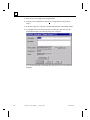
Read the agreement and click the I Agree button to accept and continue. The
Authorization dialog box appears containing a Site Code.
4.
To authorize your software, follow the instructions on the screen.
Type in the Site Code and click OK. The Enter Password dialog box appears.
5.
Enter the default password 4, 5, 6, 7 and click the Enter button.
PC Control is now running in Authorized mode.
1-6
Using PC Control Software – August 1998
GFK-1424B
1
Section 2: Using Online Documentation
When using PC Control, your primary source of information will be the Online Help.
The Online Help includes a demo to help you get started with the product and
specific help topics describing the product’s features and how to use them.
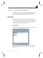
Online Help
Online Help is designed to give you quick, easy-to-access information about PC
Control topics. Use Help to get general information about a product feature, to learn
how to perform a specific procedure, or to find the definition of an unfamiliar term.
The three ways to find information in Help are by viewing the Help contents,
performing a Help search, or using context-sensitive help.
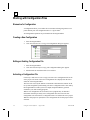
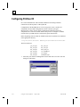
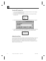
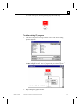
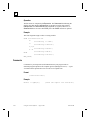
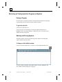
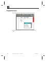
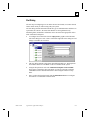
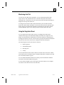
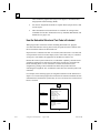
Help Contents
The Contents tab of Help shows the main topics covered in Help. To access the Help
Contents, choose the Help menu and select Contents:
Double-clicking the topic name or the book icon beside it “opens” the book and
displays the topics subheadings. To view the contents of one of the subheadings,
double-click it.
GFK-1424B
Chapter 1 Introduction
1-7
1
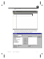
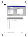
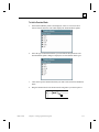
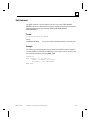
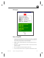
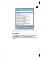
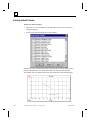
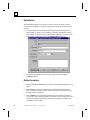
Searching Help
The Index tab of Help allows you to type the topic you are looking for or scroll
through an alphabetical list of topics. To access the Help Index, choose the Help
menu and select Search for Help On (or click the Help Search toolbar button :
To initiate a search, type the topic name in the field or scroll through the list. Doubleclick the selected topic to access help on that topic.
Context-Sensitive Help (F1)
Using context-sensitive help, you can quickly access specific information about the
active window or dialog box by pressing the F1 button.
1-8
Using PC Control Software – August 1998
GFK-1424B
Chapter
Getting Started
2
To get started using PC Control software, open the Program Editor utility. The
Program Editor utility allows you to create a new project to hold the application
program and configuration files, create application programs, and access the I/O
Configuration utility.
This chapter provides the following information:
GFK-1424B
•
Overview of the software subsystems comprising PC Control software
•
Overview of IEC 1131
•
How to change access level passwords
•
How to create and manage projects from Program Editor
•
How to create and manage application programs
•
Overview of program operation
2-1
2
Section 1: Overview of the Software
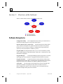
The PC Control software consists of the following subsystems:
Software Subsystems
Configuration Utility
The Configuration Utility allows you to define the I/O
structure and assign tag names to I/O points and I/O ports.
Operator Interface (PC Control GUI)
The Operator Interface utility allows
you to customize and operate the operator interface environment. The operator
interface is a series of screens, messages, or windows that are presented to the
operator to control and monitor a machine or process.
Program Editor The Program Editor allows you to create and run Relay Ladder
Logic (Ladder Diagram), Sequential Function Chart (SFC+), Structured Text, and
Instruction List programs.
Program Manager
The Program Manager prepares programs for execution
and manages the external interface to Program Execution and the I/O Scanner.
Program Execution
Program Execution executes the Relay Ladder Logic,
Sequential Function Chart (SFC+), Structured Text, and Instruction List programs.
Program Execution runs at Windows NT's REAL_TIME process priority.
I/O Scanner
The I/O Scanner scans the physical I/O devices and makes the
information available to Program Execution. The I/O Scanner runs at the
REAL_TIME process priority. The I/O Scanner retrieves all inputs from and
transmits all outputs to the physical I/O interface.
2-2
Using PC Control Software – August 1998
GFK-1424B
2
IEC 1131 Overview
IEC 1131-3 is an international standard from the International Electrotechnical
Commission. IEC 1131-3 specifies the syntax and semantics of a unified suite of
programming languages for programmable controllers.
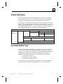
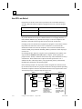
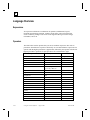
IEC 1131-3 Programming Languages
The IEC-1131-3 languages consist of textual and graphical languages. These
languages can be used together in an integrated programming environment. For
information about PC Control software enhancements to the IEC 1131-3 standard,
refer to the online help.
Textual Languages
Instruction List (IL)
Instruction List format is similar to an assembly language.
Structured Text (ST)
Structured text is best suited for complex algorithms, string and file
operations, and manipulation of data structures best done in a procedural
(text based) language. It is convenient for those who have experience
with structured BASIC, Pascal, C or other high-level programming
languages.
Graphical Languages
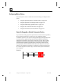
Ladder Diagram
(Relay Ladder Logic — RLL)
Ladder diagram is commonly used on programmable controllers to
construct discrete logic programs. Ladder diagrams are designed to
resemble the electrical diagram for an equivalent electrical relay logic
circuit. The ladder diagram contains two vertical power rails. The left
power rail is assumed to be an electrical current source and is energized
whenever the program is running. The power rail on the right is assumed
to be an electrical current sink. The two power rails are connected by
horizontal lines called rungs (like the rungs of a ladder) on which the
logical instructions are placed.
Sequential Function Chart (SFC)
SFC is best suited for machine sequencing control and for control
applications that have multiple operating modes, such as manual mode
and automatic mode. An SFC represents an application program as a
series of sequential steps. Steps are connected by links and control is
passed between steps via transitions as the program executes. Control
logic can be placed in the step or within an associated action attached to
the step. The control logic executes when the step becomes active.
Control passes to the next step when the transition is cleared.
Function Block Diagram
Function block diagram is best suited for analog signal processing and
any control process or algorithm that runs on a continuous basis.
Functions and function blocks appear in the FBD language as graphical
blocks labeled with their function name and inputs and outputs. Function
block diagrams consist of a network of these graphical functions and
function blocks connected by signals. This language is currently not
supported by PC Control.
GFK-1424B
Chapter 2 Getting Started
2-3
2
Quick Start
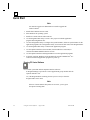
Note
You must be logged on as administrator to install or upgrade PC
Control software.
1.
Install all PC hardware and I/O cards.
2.
Start Windows NT operating system.
3.
Install PC Control software and I/O drivers.
4.
Use the Program Editor utility to create a new project to hold the application
program and configuration files.
5.
Use the Configuration utility to configure the system hardware, define I/O symbol names for the
application programs. The Configuration Utility is run from the File menu of the Program Editor.
6.
Use the Program Editor utility to construct the application program.
7.
Use the Operator Interface's Screen Editor (located under the Tools menu) to
construct the Human/Machine Interface screens.
8.
Use the Operator Interface and Program Editor to test the application programs.
9.
If desired, configure Windows NT to automatically start the CIMPLICITY PC
Control software and application programs on power up.
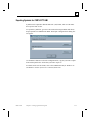
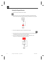
Running PC Control Software
For a control system that includes Operator Interface software:
In Program Manager, open the PC Control Applications group. Double click the
Operator Interface icon.
Or, if the Program Editor is running, choose Operator Interface from the
Program Editor Tools menu.
Note
If the PC Control runtime subsystems are not active, you are given
the option of starting them.
2-4
Using PC Control Software – August 1998
GFK-1424B
2
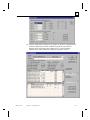
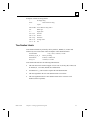
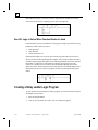
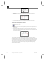
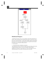
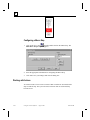
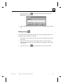
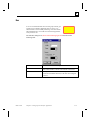
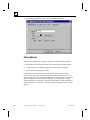
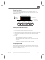
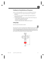
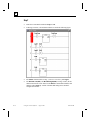
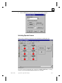
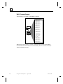
Starting the PC Control Runtime Subsystems
1.
From Program Manager, open the PC Control Applications group.
2.
Double click the PC Control Runtime icon. When the Runtime subsystems are
active the Runtime icon appears minimized at the bottom of the screen.
When the Runtime subsystems are active the Runtime icon appears on the Task Bar
or Tray at the bottom of the screen.
If the Runtime icon appears on the Tray, the mouse must be used to shut down the
Runtime Subsystems. If the Runtime application also appears on the Task Bar, it can
be shut down using the keyboard. To make the Runtime icon appear in the Task Bar,
access System Options from the Program Editor Tools menu and check the option in
the Display Properties tab.
Shutting Down PC Control Runtime Subsystems
1.
Right mouse click on the Runtime icon on the Task Bar.
2.
Select Shutdown Runtime.
Starting the Program Editor
GFK-1424B
1.
From Program Manager, open the PC Control Applications group.
2.
Click the Program Editor icon.
Chapter 2 Getting Started
2-5
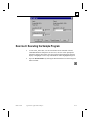
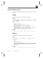
2
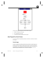
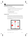
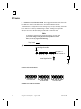
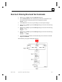
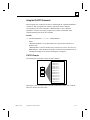
PC Control Runtime Subsystems
The Program Manager, Program Execution and I/O Scanner, subsystems are visually
represented by the PC Control Runtime icon. The Event Log has its own icon. The
subsystems consist of the following:
The Program Manager
The Program Manager prepares programs for execution and manages the external
interface to Program Execution and the I/O Scanner.
Program Execution
The Program Execution subsystems have real-time process priority, meaning CPU
time is given to Program Execution before all normal applications, including: mouse
updates and disk access.
I/O Scanner
I/O Scanner subsystems have real-time process priority, meaning CPU time is given
to I/O Scanner before all normal applications, including: mouse updates and disk
access.
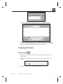
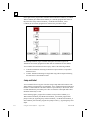
When the I/O Scanner starts up, it searches for I/O cards. If no cards are detected in
the PC backplane, a message box is displayed. Push the Simulate button to ignore the
missing hardware and run the PC Control software in simulation mode. In simulation
mode, the inputs and outputs are resident in a memory table, but the values are not
read from or written to the I/O devices. User simulation software can write to the
input memory map and read from the output memory map to simulate I/O in the
environment.
From within the Operator Interface, you can activate the Program Editor by pushing
the appropriate button or selecting the specific menu item from the Tools menu.
Event Log
The Event Log stores time stamped system events, messages and errors. The Event
Log is started and stopped automatically by the run-time subsystems. The Event Log
must be running for messages to the Output Window to function.
Note
To configure a system that is runtime only, copy an entire project
folder from a development system (make sure both have the same
path to the program and project files) to the runtime. The other way
is to temporarily give the system a developer license, make the
desired project active and then go back to a runtime license. The
runtime only system cannot change projects.
2-6
Using PC Control Software – August 1998
GFK-1424B
2
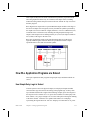
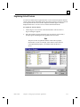
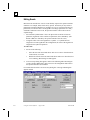
Program Editor
The Program Editor lets you organize your work on a project by project basis. You
can create and manage any number of projects from within the Program Editor.
At any one time only one project can be open. This is called the active project. Each
project has an active configuration associated with that project. When a project is
opened, the active configuration for that project is activated. When a new project is
opened all programs are cancelled.
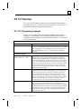
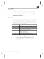
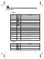
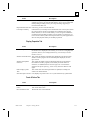
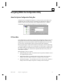
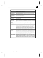
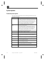
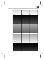
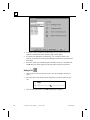
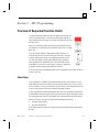
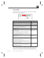
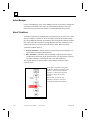
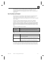
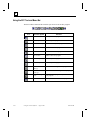
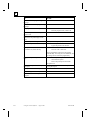
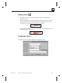
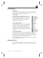
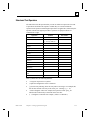
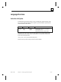
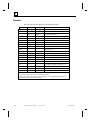
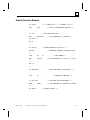
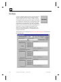
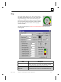
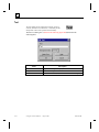
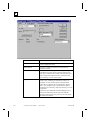
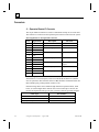
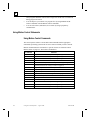
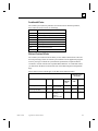
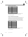
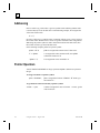
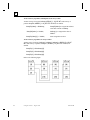
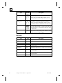
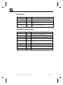
Access Levels
Access levels and access codes (passwords) are used to control access to application
programs, operator interface screens, and configuration data. There are five access
levels, with a different access code for each. The following table describes the
privileges of each level. The lowest access level is 0; each successively higher access
level has the privileges of the preceding levels.
Access Level
Privileges
0
Activate operator screens and use controls.
Select and run SFC programs from the Operator Interface.
1
Open, view, run, and stop programs.
2
Edit SFC, structured text, and instruction list programs.
Perform project management functions.
3
Edit RLL programs.
Modify the operator interface.
Modify system configuration files.
4
Change the passwords for access levels 1 to 4.
The default access code is 4567.
Note
If you have the Program Editor open, changing the access level
within the Operator Interface does not change the access level of
the Program Editor.
GFK-1424B
Chapter 2 Getting Started
2-7
2
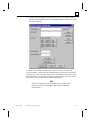
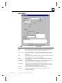
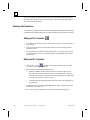
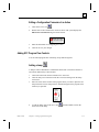
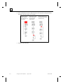
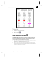
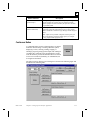
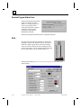
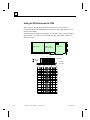
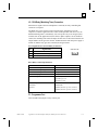
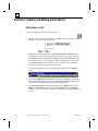
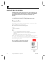
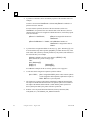
Entering an Access Code
Program Editor and Operator Interface require access codes. The Program Editor
automatically presents the access level keypad upon startup.
To Enter an Access Code:
From:
Then:
Program Editor
Click the numbers on the keypad that represent your access
code and click OK.
Operator Interface
1.
Click Access from the menu bar and select Password. A
keypad appears.
2.
Click the numbers on the keypad that represent your
access code and click OK.
To Set the Access Level to 0:
Click Cancel button on the access keypad.
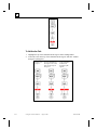
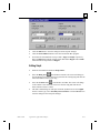
Changing Access Levels
The access code for any level can be changed only from Operator Interface with a
level 4 access code. There is one access code for each level.
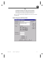
To change the access level password:
1.
Click Access from the menu bar and select Enter Password. A keypad appears.
2.
Click '*' key four times. The message: "Enter Access Level to Change."
Appears.
3.
Click the number of the access level you want to change and click OK.
4.
Click the new four digit number. The message: "Enter new password again".
5.
Click the new four digit password again and click OK. If you verify the new
password correctly the password will be changed.
Note
Click CANCEL on the keypad to set the access level to zero.
When attaching Control Functions to operator controls (in the
operator interface edit mode) an access level can be specified to
control the use of the each operator control.
2-8
Using PC Control Software – August 1998
GFK-1424B
2
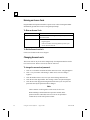
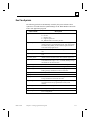
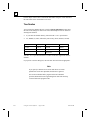
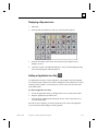
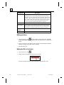
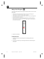
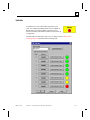
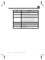
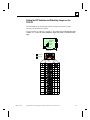
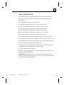
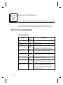
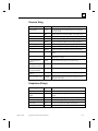
Keyboard Shortcuts for the Operator Interface
GFK-1424B
Key(s)
Action
<ESCAPE>
Aborts most operations and dialog boxes.
<ENTER>
Edits the selected control.
<DELETE>
Deletes the selected control(s).
<CONTROL>
or
<SHIFT>
While selecting controls, adds the control to the selection group if the
control is not selected or removes the control from the selection group if the
control is already selected
any arrow key
Moves the selected control(s) one pixel in the specified direction.
Chapter 2 Getting Started
2-9
2
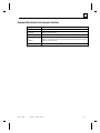
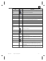
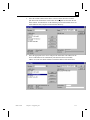
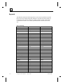
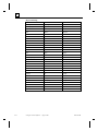
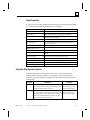
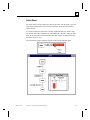
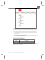
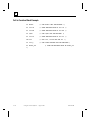
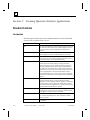
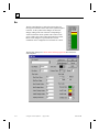
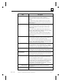
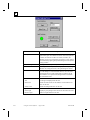
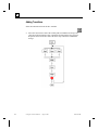
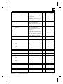
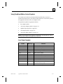
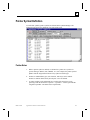
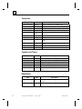
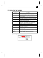
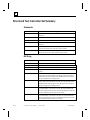
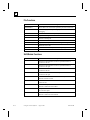
Menu Descriptions
File Menu
Item
Button
Description
New Editor
Creates a new program file.
Open Editor
Opens an existing program file.
Close
-
Closes all the windows associated with the active program file.
Save
Saves the active program file.
Save As
-
Saves the active program under a different name.
Save All
-
Saves all open program files and related project information.
Print...
Prints a program.
Print XRef...
-
Prints program variables and where and how often they are used in
the program. This option appears only when a program file is open.
Print Setup
-
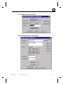
Lets you to change the printer and printing options.
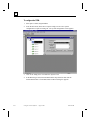
New Config
-
Opens the Configuration Utility with a new I/O configuration file.
Open Config
-
Opens an existing I/O configuration file in the Configuration Utility.
Save Config
Saves the active configuration.
Save Config As
Saves the active configuration with a new name or path.
Import CSV to
Config
Imports a comma separated configuration file.
Export Config to
CSV
Exports the active configuration to a comma separated file that can be
accessed by a text editor or spreadsheet.
Recently Used File
List
-
List of the last four files accessed by the Program Editor.
Exit
-
Closes the PC CONTROL software. If the unsaved programs are
open, you are prompted to save them.
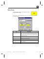
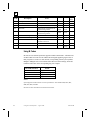
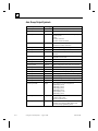
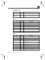
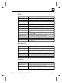
Edit Menu
Item
2-10
Button
Description
Undo
Undoes the last action.
Redo
Redoes the previously undone action.
Cut
Cuts the selected object and places it on the clipboard.
Using PC Control Software – August 1998
GFK-1424B
2
Item
Button
Copies the selected object and places it on the clipboard.
Paste
Pastes the contents of the clipboard.
Delete
-
Select All
Deletes the selected object.
Selects all text in an ST or IL document.
Edit Element...
-
Opens the dialog box for the selected program element.
New Element
-
Insert an SFC or RLL element at the selected point in the program.
New Function Block
-
Inserts a function block element at the selected point in the program.
Available only when an RLL program is open for edit.
New SFC Element
-
Inserts a new SFC element.
Step Properties
-
Edits an SFC step.
Insert ST Statement
-
Inserts a Structured Text statement.
Insert ST Function
Calls
-
Inserts a Structured Text function or function block.
Insert IL Statement
Insert IL Function
Calls
Find...
GFK-1424B
Description
Copy
Inserts an Instruction List statement.
-
Inserts an Instruction List function or function block.
Finds the specified text.
Find Next
Finds the next occurrence of the specified text.
Find Prev.
Finds the previous occurrence of the specified text.
Replace...
-
Replaces the specified text with new text.
Go To…
-
Jumps to the specified rung number. Available only when an RLL
program is open for edit.
Trace...
Searches for the next occurrence of a output coil with the same
symbol name as a selected contact. Available only when an RLL
program is open for edit.
Insert Mode
Inserts new elements before the selected point.
Append Mode
Appends new elements after the selected point.
Boolean Transitions
-
When editing an SFC, sets the default transition for all open SFC
programs to the Boolean type, instead of the RLL type. Does not
change existing Transitions. Available only when an SFC program is
open for edit.
Lock Algorithms
-
When editing an SFC, lets you add password protection to Step
algorithms. Available only when an SFC program is open for edit.
Chapter 2 Getting Started
2-11
2
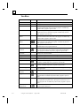
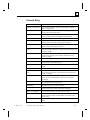
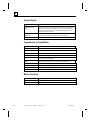
View Menu
Item
Description
Toolbar
-
Displays editor commands as icons.
Status Bar
-
Displays the editor window status bar.
Contact/Coil Bar
-
When editing an RLL program, the Contact/Coil bar displays the
program elements that can be used in the program. Available only
when an RLL program is open for edit.
SFC Bar
-
When editing an SFC program, the SFC toolbar displays the program
elements that can be used in the program. Available only when an
SFC program is open for edit.
Function Block
Palette
-
When editing an RLL program, the Function Block Palette displays
the function blocks that can be used in the program. Available only
when an RLL program is open for edit.
Application Icon
Palette
When editing an SFC program, the Application Icon Palette displays
the Icons that can be used in the program. Available only when an
SFC program is open for edit.
Accessory Bar
Displays the Structured Text or Instruction List accessory bar that
automatically inserts program statements.
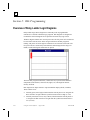
Watch/Force
Variables
At runtime, this window displays variables and their current values.
You can specify (force) new values for them to help in debugging
your program. Available only when a program is open for edit.
I/O Faults
Displays the I/O fault window.
Output Window
-
Displays message that occur at runtime appear in this window.
Program Status
-
Opens the Program Status window.
Show Parse Errors
Displays the parser error window.
Program Comments
Displays or hides any program comments that you enter into the
program. Available only when a program is open for edit.
Scale to Fit Window
Resizes the program so that it fits into the currently displayed
window. Available only when a program is open for edit.
RLL Warnings
-
Turns notification of RLL warnings on or off. Warnings occur during
a program parse.
Disp. Symbol
Location
Displays the rack/slot/point information for I/O symbols.
Toggle FB Details
Turns On/Off the display of symbol names and real time data in RLL
function blocks. Available only when an RLL program is open for
edit.
All Steps
Show Symbol
Enumerations
2-12
Button
-
When editing an SFC program, this option lets you specify that steps
be displayed showing their names, descriptions, associated icons, or
their program code. Available only when an SFC program is open for
edit.
Turns on the symbol enumerations that have been selected in the
System Options dialog box.
Using PC Control Software – August 1998
GFK-1424B
2
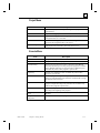
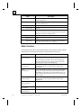
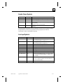
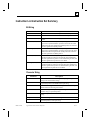
Project Menu
Item
Description
New
Creates a new project for storing related application programs and
configurations.
Open
Opens an existing project.
Copy
Copies an existing project (including all application programs and
configuration files) to a new name.
Rename
Renames an existing project. Has no effect on the application
programs and configuration files in the project.
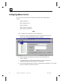
Activate Config.
Activates the current configuration file. The current configuration file
is displayed on the status bar at the bottom of the screen.
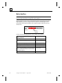
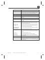
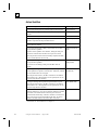
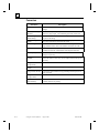
Execute Menu
Item
GFK-1424B
Description
Parse
Compiles the program
Run
Compiles then executes the program.
Run with Debug
Executes the program until it reaches a Structured Text BREAK
statement and then stops executing and put the program in a "Break"
status. BREAK statements are ignored if a RUN command is given.
Available only when an SFC program is open for edit.
Single Step
Executes one command at a time. Available only when an SFC
program is open for edit.
Run with Restart
Marks the program to begin executing every time the runtime is
started. A program that has been Aborted or is Faulted will no longer
be marked to run with restart.
Stop
Stops executing program where it was stopped. When you restart the
program, it begins executing at the point it left off. Available only
when an SFC program is open for edit.
Abort
Stops executing program. When you restart the program, it starts
executing at the beginning of the program.
Reset Estop and clear I/O
Faults
Resets the I/O drivers and reestablishes communication with the I/O
hardware.
Startup Runtime
Subsystems
Startup the runtime subsystem programs.
Chapter 2 Getting Started
2-13
2
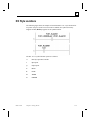
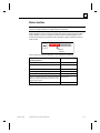
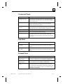
Icon Menu
Item
Description
New App Icon
Accesses the Application Icon Step Library allowing you to create
predefined Steps in the library.
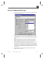
Edit App Icon
Edits predefined Steps in the Application Icon library.
Delete App Icon
Deletes predefined Steps in the Application library.
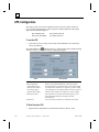
Tools Menu
Item
Operator Interface
Button
-
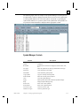
Symbol Manager
Description
Starts the integrated Operator Interface
Accesses the Symbol Manager allowing you to create and edit
variables.
Action Manager
-
Accesses the Action Manager allowing you to rename and delete SFC
actions.
RLL Transition
Manager
-
Accesses the Transition Manager allowing you to rename and delete
SFC, RLL transitions
Export Symbols
-
Exports all Global Symbols to a *.SNF file. Available only with the
CIMPLICITY HMI interface.
System Options
-
Opens a dialog box that allows you the change the Heap Size and the
memory variable Data Table size, display, and symbol enumeration
preferences.
License Menu
Item
2-14
Description
Authorize
This option is used to create a software "License" for the PC CONTROL
Software. Call or Fax your "Site Code" in to GE Fanuc Automation to
receive a "Site Key" to authorize your software. This option is only activated
when the software has been started in demo mode.
Upgrade Authorization
When you are ready to increase the functionality of PC CONTROL the
Upgrade Authorization option can be used to generate a new "Site Code".
This option is only enabled after the software has been authorized.
Register Transfer
Use this option to begin the process of transferring a software license from
one computer to another. Place a blank floppy disk in a unauthorized
computer and select "Register Transfer" to write a unique signature file for
the computer. This option is only active when the software has been started in
demo mode.
Using PC Control Software – August 1998
GFK-1424B
2
Item
GFK-1424B
Description
Transfer Out
Transfer Out is the second step in the process of transferring a software
license from one computer to another. After completing the Register Transfer
process on the unauthorized computer, place the floppy disk in the authorized
computer and select the Transfer Out option. The software license will be
removed from the computer and placed on the floppy disk. This software
license can only be transferred to the computer that wrote the original
signature file to the floppy. This option is only active on an authorized
computer.
Transfer In
Transfer In is the last step in the process of transferring a software license
from one computer to another. Place the floppy disk in the computer that has
had the software license transferred. Select Transfer In to move the software
license to the computer. A software license can only be transferred to the
computer that wrote the original signature file to the floppy.
Temporary Authorization
Temporary authorization permits you to temporarily provide full
development authorization on a run-time only system. Each run-time only
system comes with 30 minutes of free temporary authorization; additional
time can be purchased. Valid for run-time only systems. To obtain the a free
copy of the Temporary Authorization utility, call the phone number given in
the Authorization dialog box.
Selecting temporary authorization displays the Temporary Authorization
buttons and the amount of temporary authorization time remaining:
OK - turns on temporary authorization and starts the temporary authorization
timer (providing there is time remaining).
Cancel - returns to run-time only.
Add More Minutes - allows you to purchase additional temporary
authorization time for this system. Call the phone number given in the
Authorization dialog box and provide your code from the Code field. You
will be given a key in return that must be entered in the Key field to add the
additional temporary authorization time.
Reset Original
Authorization
Turns off temporary authorization and stops the temporary authorization
timer. Valid for run-time only systems.
Emergency Authorization
Provides full authorization for all features for four days. After four days, PC
CONTROL will return to demo mode. Once it has been selected, you are
warned that this is a one-time authorization until the hard drive has been
reformatted. If you select to continue, a signature is written to the hard drive.
Chapter 2 Getting Started
2-15
2
Toolbars and Status Bar
Tool bars contain push buttons for commonly executed functions.
Standard Toolbar
Button
Tool
New
Open
Save
Undo
Redo
Cut
Copy
Paste
Insert before
Insert after
Print
About
Context help
Display Comments
Scale to fit window
Symbol Manager
Watch window
Boolean transition mode
2-16
Using PC Control Software – August 1998
GFK-1424B
2
RLL Toolbar
Button
Tool
Select
Contact
Rung Label
Coil Tool
Jump Coil Tool
Transition Coil Tool
Branch Tool
New Rung Tool
SFC Toolbar
Button
Tool
Selector Tool
Step
Macro Step
Action
Transition
Label
Jump
Loop
Select diverge
Simultaneous diverge
Application icon
Add Comment
GFK-1424B
Chapter 2 Getting Started
2-17
2
Status Bar
The Status Bar is located at the bottom of the Program Editor window. The status bar
shows the name of the current configuration and the status of:
•
NUM lock
•
SCROLL lock
•
CAPS lock
•
keyboard keys
•
insert and append modes
Answers to Common Questions
Does PC Control Require a PLC?
•
PC Control does not require a PLC device to do logic execution.
•
PC Control performs logic execution in the PC without the need for a PLC.
•
PC Control can use PC based scanner cards to control PLC style I/O racks,
modules and other devices.
Does PC Control Perform Parity Checking?
PCs can be purchased and configured to provide parity checking on all system
memory.
The PC Control does not do parity checking on application programs, but it does do
background checksum calculations on all running application programs. If an error is
detected, the application program is stopped, faulted and the operator is allowed to
determine what should be done to recover.
What Happens on a Parity Error?
If a parity error is detected in the system, Windows NT will stop and display a error
screen with a blue background indicating a Data Bus Error and the location where the
error was detected. The system must be rebooted to continue.
The PC Control system makes use of Watchdog timers and the Safe State I/O
features available on some I/O systems to detect loss of PC Control controller
activity, and to place the Outputs into a predetermined safe condition.
For more information contact GE Fanuc Automation.
2-18
Using PC Control Software – August 1998
GFK-1424B
2
What Happens on Power Loss?
The PC and the I/O system will go to the power loss state. When power is reapplied,
the I/O system will assume the state that it normally assumes or has been configured
to assume when power and control is lost. When nonvolatile or battery backed
memory is available in the system, a PC CONTROL application can restart the I/O
and application programs from the point of interruption.
Can PC Control Software be Automatically Started?
Windows NT can be configured to start the PC Control software and the application
program automatically upon boot up.
For more information on this topic, refer to “Configuring Programs to Execute
Automatically” in Chapter 5
Can PC Control Software Work with an Uninterruptible Power Supply
Windows NT can be configured to work with an Uninterruptible Power Supply
(UPS) that can supply power to the system when the AC line is lost. Windows NT is
notified with an interrupt when the AC line is lost and can be made to take
appropriate actions in response.
PC CONTROL can also use power failure and low battery signals received from the
UPS to perform user programmed actions. For more information, see “UPS
Configuration” on page 2-30.
GFK-1424B
Chapter 2 Getting Started
2-19
2
Section 2:
Working with Projects and Applications
Managing Projects
Project management allows organization of work into logical divisions called
projects. Each project contains a group of program, configuration, and operator
interface files that are used for a common purpose.
The Program Editor is used to edit RLL, SFC, Structured Text, and Instruction List
application control programs. All project management functions are performed from
the Program Editor. The following notes pertain to projects:
•
The Program Editor can have only one project open at a time.
•
The project name should identify the common purpose of the files.
•
The active project is displayed on the Program Editor window title bar.
Creating a New Project
1.
Start Program Editor.
2.
Click Project on the menu bar and select New. The New Project dialog box
appears.
3.
Type the name of the new project and click OK.
Note
If there was an active project open, it is closed and the new project
becomes the active project.
Opening a Project
1.
Start Program Editor.
2.
Click Project on the menu bar and select Open. The Open Project dialog box
appears.
3.
Click the project you want to open and click OK.
When a project is opened it becomes the active project. The previously active project
is closed along with any open program files. When a project is opened all program
files that were previously open in the project are opened again and the configuration
file that was last active in that project is activated.
2-20
Using PC Control Software – August 1998
GFK-1424B
2
Copying a Project
1.
Start Program Editor.
2.
Click Project on the menu bar and select Copy. The Copy Project From dialog
box appears.
3.
Click the project you want to copy and click OK. The Copy Project To dialog
box appears.
4.
Type the name of the copy and click OK.
When a project is copied, all of the program, operator interface and configuration
files in that project are copied into the new project and the new project becomes the
active project. Program files which were previously open in the source project are
copied to the new project and opened. The configuration file which was active in the
source project is copied to the new project and activated.
Renaming a Project
1.
Start Program Editor.
2.
Click Project on the menu bar and select Rename. The Rename Project From
dialog box appears.
3.
Click the project you want to rename and click OK. The Rename Project To
dialog box appears.
4.
Type the new name of the project and click OK.
After a project is renamed it becomes the active project.
Activating a Configuration
1. Select Activate from the Project menu. The Select Global Configuration File
dialog box appears. It displays a list of configuration files defined for the current
project.
2.
GFK-1424B
Select the configuration you want to activate and click OK.
Chapter 2 Getting Started
2-21
2
Working With Application Programs
Program management lets you create and save Relay Ladder Logic (RLL), Sequential
Function Chart (SFC), Structured Text (ST), and Instruction List (IL) programs. You
can open many programs at the same time. Use the Window menu to switch between
open programs or use the mouse to click on a partially visible program and bring that
program's window to the top. The active programs are displayed on the Program
Editor title bar.
Creating a New Program
To create a new program in a new window:
1.
Click File and select New or click the new program button on the editor tool bar.
A dialog box is displayed that allows you to specify a new Relay Ladder Logic (RLL)
program, Sequential Function Chart (SFC), Structured Text Document, or Instruction
List Document.
2.
Select the type of program you want to create and click OK. A new editor
window of the appropriate type opens. The program is given a default name
(RLL1, for example).
Opening a Program
To open an existing program in a new window:
Click File and select Open or the open program button on the editor tool bar.
You can open many programs at the same time. Use the Window menu to switch
between open programs or use the mouse to click on a partially visible program and
bring that program's window to the top. If no project is active when a file open
command is executed, the new project or the open project dialog box will be
displayed.
2-22
Using PC Control Software – August 1998
GFK-1424B
2
Saving a File
To save the active program to its current name and directory:
Click File and select Save or the Save Program button on the editor tool bar.
When you save a program for the first time, the Program Editor displays the Save As
dialog box so you can name your program. If you want to change the name or
directory of the active program before you save it, use the Save As file command.
To save the file with a new name
Click File and select Save As. The Program Editor displays the Save As dialog box
so you can change the name of the program.
Printing a Program
To print an SFC, RLL, ST, or IL program:
Click File and select Print or the Print Program button on the editor tool bar.
To change the printer setup, click File and select Print Setup menu command or,
from the print dialog box, push the Setup button.
When printing a SFC program, the SFC diagram will be printed first. Actions
embedded in the SFC are printed alphabetically following the SFC diagram and any
embedded Relay Ladder Logic Transitions will be printed alphabetically following
the embedded Actions.
GFK-1424B
Chapter 2 Getting Started
2-23
2
Printing Program Cross-References
This lists symbol usage for a program. It lists all symbols in a configuration, the
number of times they are used in the program, and their location in the program. For
example, the rung number and contact or coil type for an RLL program.
To print program cross-references
•
Select Print Xref from the File menu.
Managing Application Programs
Program management allows you to create and save Relay Ladder Logic (RLL) and
Sequential Function Chart (SFC) programs. You can open many programs at the
same time. The active program is displayed on the Program Editor title bar.
To access other open programs in Program Editor:
1.
Click Window on the menu bar.
2.
Click the program you want to view.
Note
You can also use the mouse to click on a partially visible program
and bring that to the front.
Commands that are executed from the menus or by pushing buttons on the tool bars
are performed on the active program.
Closing Application Programs
To close a program:
Click File on the menu bar and select Close.
or
Click the Close button at the upper-right corner of the window.
2-24
Using PC Control Software – August 1998
GFK-1424B
2
Viewing Programs
When a program is opened the contents of the program are displayed in a window.
You can open many windows of the same RLL, SFC, IL, or ST program.
To access other open programs in Program Editor
•
Select the program from the list under the Window menu.
•
Use the mouse to click on a partially visible program and bring it to the front
Sizing a Program to Fit the Window
Click View on the menu bar and select Scale to Fit Window.
or
Toggle the view by clicking the Scale to Fit Window button on the tool bar.
Scale to fit window can also be used to scale action or transition RLL programs
embedded in a SFC program.
To navigate using the Scale To Fit Window
1.
Scale the program to fit the window.
2.
Select the desired element.
3.
Remove the window scaling. The view will scroll the selected element to the
center of the screen if it is not in the last active unscaled view.
Turning Comments On and Off
Descriptive comments can be added to application programs to document functions
of the program. The View Comments mode affects all open programs.
To toggle the View Comments mode:
Click View on the menu bar and select Program Comments.
or
Use the View Comments button on the Tool bar to toggle the View Comments mode.
Note
A check mark next to Program Elements and a depressed View Comments button
indicates that comments are visible.
GFK-1424B
Chapter 2 Getting Started
2-25
2
Setting System Options
You can use the System Options dialog box to set parameters that affect the behavior
and appearance of the control system.
Adjust Memory Sizes Tab
Field
Description
Display Style
Free Physical Memory
Current Heap Size
Requested Heap Size
2-26
Displays memory size options in Decimal or Hex.
The current free physical memory available on the computer. This cannot be
edited, but depends on the type and number of open Windows applications.
This shows the current Heap setting and cannot be edited. The Heap is
memory allocated (on start-up) for the control system. The Heap is used up by
open application programs and symbols. As it is used up, this setting may
need to be increased. However, the larger the Heap size, the less memory will
be available for other Windows applications
If the Heap needs to be increased (or can be decreased), provide a new Heap
size here. The Heap can be larger than physical memory, as it will use virtual
memory from the swap file. If you run out of control system memory during
an editing session, you will get a message suggesting to increase the Heap
Size.
Using PC Control Software – August 1998
GFK-1424B
2
Field
Description
Current Data Table Size
This is memory used for symbols and depends on the symbol data type. For
example, large arrays use more data table memory. If you run out of data table
memory during an editing session, you will get a message suggesting to
increase the data table size.
Requested Data Table Size If necessary, provide a new data table size.
Lock Heap in Memory
If this field is set, it will improve the determinism of the control system. When
the control system is started, it will attempt to lock the Heap into physical
RAM; otherwise, it can use virtual memory. You are not given an indication
of whether locking the Heap in memory was successful or not; therefore, it is
best to start the control system run-time system before any other application to
allow as much physical memory for the Heap as possible.
Display Properties Tab
Field
Description
Runtime Tray Icon
If set, displays the Runtime icon in the tray; otherwise, it is also displayed in
the task bar. If it is displayed in the task bar, you can access it using keyboard
operations; however, if it is displayed in the tray, it is necessary to use the
mouse to access it.
Number of Decimal Places This controls the number of decimal places displayed in the function block
details in an RLL program. The more decimal places displayed, the more
space is used.
Number of FB Symbol
This controls the length of space for displaying characters in the function
Characters
block details in an RLL program (not necessarily the actual number of
characters). A standard character size of an upper case X is assumed. If
characters take up less space (e.g., lower case I), then more characters will
appear.
Editor Display Update
This controls how often the Program Editor is updated; for example, the
Time
values in the Watch Window.
Show IEC Style Locations If set, displays I/O points in IEC 1131-3 syntax rather than by symbol name.
Fonts & Colors Tab
Field
Description
Fonts
Colors
Reset to Default Colors
GFK-1424B
Sets the fonts in the program editors.
Sets various editor colors.
Restores all colors to their defaults.
Chapter 2 Getting Started
2-27
2
Symbol Enumeration Tab
Enumerations refer to the elements of a complex symbol. That is, a symbol that has
elements that can be individually accessed: structures, function blocks, etc. The
following check boxes work with the Show Symbol Enumerations command on the
editor View menu. If the associated check box is set and Show Symbol Enumerations
is enabled, then the respective enumerations are visible in symbol lists. If the check
box is reset or Show Symbol Enumeration is disabled, the enumerations are not
visible in symbol lists.
Showing symbol enumerations (depending on the number of symbols) can affect
performance as you are using the editors, since more symbols will need to be loaded
into the symbol lists.
Note: Even with enumerations off, if you drag a symbol from the Symbol Manager
and drop it, a list box appears with that symbol's enumerations from which you can
select the enumeration you want to use.
Field
Show Function Block
Enumerations
Show User Type
Enumerations
Show Axis Enumerations
Show Axis Group
Enumerations
Show System Object
Enumerations
2-28
Description
Shows the function block instance inputs and outputs.
Shows elements within an instance of a user type.
Shows axis element symbols.
Shows axis group element symbols.
Shows the variables associated with instances of timers (TMR),
PIDs, and PRGCBs.
Using PC Control Software – August 1998
GFK-1424B
2
IEC Style Locations
The following figure shows an example of normal and IEC 1131-3 style locations for
I/O points. (Display Symbol Locations must be enabled.) If a symbol is memory
mapped variable, Memory appears for the symbol location.
The IEC 1131-3 symbol location syntax is as follows:
GFK-1424B
%
Directly represented variable
I
Input point
Q
Output point
X
BOOL
B
BYTE
W
WORD
D
DWORD
Chapter 2 Getting Started
2-29
2
UPS Configuration
The control system can work in conjunction with a UPS. The control system can
receive signals from the UPS in order to prepare an orderly shutdown. The signals
appear in the Symbol Manager as:
RT_POWER_FAIL
RT_LOW_BATTERY
Power failure detected.
Low battery detected.
To use the UPS
•
Locate the PC Control Applications menu from the Windows Start menu and
choose UPS Monitor.
The UPS Monitor icon
appears in the tray. Configure the UPS by double-clicking
on the icon. The PC Control UPS Monitor dialog box appears.
Item
UPS is installed on:
UPS Configuration
Power failure signal
UPS Interface Voltage
Low battery signal
UPS Interface Voltage
UPS Characteristics
UPS Service
Description
Select the serial port to which the UPS is connected.
Refer to your UPS documentation to fill in these fields.
Check this option if the UPS provides a power failure signal.
If checked, select whether it is a negative or positive voltage.
Check this option if the UPS provides a low battery signal. If
checked, select whether it is a negative or positive voltage.
If the UPS does not provide a low battery signal, you can
enter UPS characteristics by referring to the UPS
documentation.
You can set these preferences as needed for your system.
To Shut Down the UPS
•
2-30
Right-click the UPS Monitor icon and choose Shutdown Memory UPS.
Using PC Control Software – August 1998
GFK-1424B
2
Backing Up and Restoring Variables
The UPS monitor sets the variable (RT_POWER_FAIL or RT_LOW_BATTERY)
when the respective event occurs. You can write application logic to save values to a
file on the hard disk and then read those values in on start-up to restore values.
Sample Logic for saving variables:
IF RT_LOW_BATTERY THEN
savedata.int1:= ImportantValue;
(* repeat for all information to be saved *)
OPENFILE(FCBVar, FILE:= "Backup.dat");
WRITEFILE(FCBVar, IN:= savedata );
CLOSEFILE(FCBVar);
END_IF;
GFK-1424B
Chapter 2 Getting Started
2-31
2
Section 3:
Program Operation Overview
Activate Configuration
Activating a configuration causes the following actions:
•
Initializes global memory.
•
If outputs are configured disabled, enables interface, sets outputs to disabled
state (force won't work) and starts scanning.
•
If outputs are configured enabled, sets default state and starts scanning.
First Scan with Active Configuration
The following occurs on the first scan:
•
Local and function block variables are initialized.
•
RT_FIRST_SCAN set high for first scan of first running program.
•
Logic is solved.
•
I/O is updated and the sequence repeats.
Power-down Sequence
The following occurs on the last scan :
2-32
•
The program does not receive any advance notification of an impending
shutdown and cannot take any specific action.
•
Interface modules set disable state of I/O according to individual design.
Using PC Control Software – August 1998
GFK-1424B
2
Normal Operation
The following occurs during normal operation:
GFK-1424B
•
All actions associated within a step are solved once each scan a step is active
(depends on the action qualifier).
•
Actions are solved before the structured text within a step is solved.
•
If a transition associated with a step becomes TRUE, the I/O is updated again
after which all the appropriate actions (not pulsed, inactive delayed, or limited
(inactive)) are solved by turning off all output coils except latched coils.
Function blocks are not solved. The I/O is updated and then the next active steps
are solved the following scan.
•
If structured text is used within a step, then the transition is not evaluated until
all structured text statements have been completed.
•
All structured text statements within a FOR loop are executed one iteration per
scan unless a NOWAIT statement is encountered which causes the loop to
complete all iterations in a single scan.
•
All structured text statements in a step are executed once during the first scan the
step is active and are not repeated during subsequent scans.
•
All statements within a WHILE loop will continue to be executed until the
WHILE condition becomes FALSE.
•
The normal execution sequence is: update I/O, solve logic, then repeat.
Chapter 2 Getting Started
2-33
2
File Names
The following list describes the file types by extension that are located in the project
folder:
_gprog.bbn
Binary global configuration file.
_gprog.st
Structured text version of the global configuration.
CFG
Configuration file
CSV
Comma separated variable file
DAT
Environmental parameters for program files
IL
Extension for Instruction List programs
OPI
Operator interface files.
R**
Extension for RLL programs.
S**
Extension for SFC programs
SBN
Binary file executed by the runtime engine.
SFR
Stores redo information.
SFU
Stores undo information.
SFX
Stores information for canceling online edits.
SNF
Shared name file
SST
Structured text version of the SFC program.
ST
Extension for Structured Text programs
SWC
Stores names of symbols added to the watch window.
Note
Files with RLL, OPI, SFC, CFG, ST, IL extensions constitute the
source for programs. Only these files need to be copied to transfer
an application.
2-34
Using PC Control Software – August 1998
GFK-1424B
Chapter
Configuring I/O
3
Once a project has been created, the next step is usually to create a System
Configuration for the project. The System Configuration contains a collection of
hardware specific information and global variables that are used across all the control
programs in a given project.
Ideally before configuring your system's I/O, you will install the I/O interface
board(s) and the I/O. But you can configure your system before installing the
hardware by clicking the Simulate button at the board level dialog box for the I/O
interface board(s) you are using.
For information on installing and configuring interface boards, refer to the following
appendices:
I/O System
Board
Cat. No.
Appendix
Genius
PCIM
IC660ELB921 (one port)
IC660ELB922 (two ports)
Appendix A
Series 90-30
PCIF1
IC693PIF301
Appendix B
Series 90-30
PCIF2
IC693PIF400
Appendix C
This chapter provides the following information:
GFK-1424B
•
Overview of System I/O Configuration
•
Configuring Genius I/O
•
Configuring Series 90-30 I/O
•
Configuring Other Field Buses
•
Dynamic Data Exchange (DDE)
•
Import/Export Configuration
3-1
3
Section 1:
Overview
The System Configuration dialog box contains a collection of the hardware specific
information and global variables that are used across all the control programs in a
given project.
The configuration tells the software what interface cards are in the computer and
what I/O are attached to those cards. Using the configuration editor, you can assign
symbol names to I/O points. You can also enter comments regarding the function of
particular elements.
The configuration editor takes you step by step through the configuration process.
You start by naming the system (the computer) you are working on and defining the
program scan time. The PC slots follow this on the system and the control system
cards (not the basic computer cards) in each slot, and then to each I/O module
connected to the card, and finally the I/O points.
If a card is a communications card or I/O scanner, the configuration goes even deeper
to describe remote racks, slots, boards etc.
The following figure shows the configuration levels for simple onboard I/O:
Help With Hardware Conflicts
There are several settings that must be properly configured to communicate with
most interface cards. The most common are: the data port address, the memory base
address, and the interrupt. For the interface card to work properly the jumper setting
on the card must match the setting in the Define Board dialog box AND not conflict
with other hardware in the PC.
IMPORTANT:
The best way to figure out what resources your current hardware devices are taking
up is to look in the NT Diagnostics in the Administrative Tools Program Group. The
Resources tab will display most of the hardware resources that are in use on your
system. Be aware that some devices that are in use may not report this usage to the
NT diagnostics, and devices that are not currently in use will not be reported, but
WILL still cause conflicts. The NT diagnostics are just a good place to start.
3-2
Using PC Control Software – August 1998
GFK-1424B
3
For more information on avoiding conflicts, refer to:
I/O System
Board
Cat. No.
Appendix
Genius
PCIM
IC660ELB921 (one port)
IC660ELB922 (two ports)
Appendix A
Series 90-30
PCIF1
IC693PIF301
Appendix B
Series 90-30
PCIF2
IC693PIF400
Appendix C
Data I/O Port
The data I/O port is often used by the device driver to communicate with the card.
Some port addresses are standard across most PCs. The following list identifies
common port uses:
COM1: 3F8-3FF
COM2: 2F8-2FF
COM3: 3E8-3EF
COM4: 2E8-2EF
LPT1: 378-37A
Floppy: 3F0-3F7
Video: 3B0-3BB and 3C0-3DF
Memory Address
The memory address is used to set-up a shared memory area for the interface card.
Normally memory from C8000-DFFFF will be available. This area memory is
normally used by special-function cards, such as an interface card. For example: if
the card uses 4000 (hex) bytes of shared memory and starts at D0000, it will use
D0000-D3FFF.
Interrupt – IRQ
The interrupt is used to communicate with the card. Valid interrupt values are
between 0 and 11.
Some interrupt levels are standard across most PCs and should not be used. Here is a
list of common uses:
COM1 and COM3: IRQ4
COM2 and COM4: IRQ3
Floppy: IRQ6
LPT1: IRQ7
IRQ1 and 2 are always in use by the system hardware.
GFK-1424B
Chapter 3 Configuring I/O
3-3
3
Working with Configuration Files
Elements of a Configuration
A configuration allows you to define the I/O structure and assign tag names to I/O
points and I/O ports. All configurations have a *.cfg file name.
All configuration operations are performed from the Program Editor.
Creating a New Configuration
1.
Start the Program Editor.
2.
Click File and select New Config. The configuration dialog box appears.
Editing an Existing Configuration File
1.
Start the Program Editor.
2.
Click File and select Open Config. The configuration dialog box appears.
3.
Edit the fields as desired and click Close and Save.
Activating a Configuration File
Click Project and select Activate Config to activate a new configuration file for the
active project. The name of the active configuration file is displayed on the lower
status bar of the Program Editor.
The active file is used by the runtime environment to determine the structure of the
I/O systems and global symbol naming. The active configuration file is also used by
the Program Editor to make system level Input, Output and Memory symbols
available to you while creating programs.
When a new configuration file is activated, active programs may be aborted if
information from the previously active configuration does not exist in the new
configuration. The activation of a configuration file is recorded in the active project.
Whenever that project is opened, the active configuration file for that project will be
activated.
3-4
Using PC Control Software – August 1998
GFK-1424B
3
Navigating Within the Configuration Utility
About the System Configuration Dialog Box
Using the System Configuration dialog box, you can provide a system name to the
configuration. The file name must be a valid DOS type eight character name. No
spaces are allowed. The system name in the example shown below is “Washer”.
Configuration files are stored by default in the current project directory.
I/O Scan Rate
You configure the I/O scan interval in the System Configuration dialog box. The I/O
Scan specifies the intervals at which control programs update the I/O and execute
program logic. Lower priority Windows tasks are interrupted by the I/O scan. Each
I/O scan active control programs begin execution and run until completion.
Before program logic is solved, the I/O Scanner reads inputs. After the control logic
is executed, outputs are written. The executing time of control logic is variable, since
the numbers and type of instructions active in any I/O scan interval is variable. Once
the outputs are updated, the control task is suspended and other lower priority NT
tasks resume execution.
When defining a scan rate, consider:
GFK-1424B
•
Minimum input pulse width - the minimum time an input must maintain a state to
be recognized by the software.
•
Minimum throughput - the minimum time for the control system to produce a
change in state of an output in response to a change in state of an input.
•
Maximum throughput - The maximum time for the control system to produce a
change in state of an output in response to a change in state of an input.
Chapter 3 Configuring I/O
3-5
3
Using the Define Board Dialog Box
Each type of I/O board has a slightly different dialog box for configuring I/O points.
For more specific information about configuring I/O points, see the help file for the
driver you are using.
1. From the configuration dialog box, click Define Board.
2. Set the board attributes as appropriate and click OK.
3-6
Using PC Control Software – August 1998
GFK-1424B
3
Section 2: Configuring GENIUS I/O
The PC Interface Module (PCIM)
A PCIM (PC Interface Module) Board is used to establish a connection between a
PC and a Genius I/O System. There are two types of PCIM Boards: Single and Dual
Port. Each port on a PCIM Board is used to communicate on a given Genius I/O bus.
Each Genius I/O bus can support up to 30 I/O Blocks.
The PCIM Board Definition Dialog is used to define the configuration of the PCIM
Board's hardware and the I/O Blocks on the connected Genius I/O bus(es).
Configuring the PCIM
1.
If you have not configured the PCIM using the PCIM Configuration Utility
(PCU), click the Run PCIM Configuration Utility button. This starts up a
separate utility allowing you to enter a number of configuration parameters for
the PCIM. The Online Help in this utility provides instructions on how to install
and configure the PCIM.
2.
Once you have configured the PCIM and exited the PCU, click the Read PCIM
Params From Registry button. This opens a window containing a list of
configured PCIM boards.
3.
Select the appropriate PCIM from the Model No list.
4.
To test the PCIM configuration, click the Test PCIM Configuration button. Both
lights on the PCIM should turn ON.
PCIM Board Definition Dialog Box
Name
The Name field is used to specify the 'name' of the PCIM Board in the configuration.
The Name is used to describe the Board in the I/O Point locations in the rest of the
software.
Model No
There are two valid models, Single and Dual Port. The Single Port Board only
supports one Genius I/O bus while the Dual Port model will support two buses. The
PCIM Board Definition Dialog will only let you define the I/O and hardware
GFK-1424B
Chapter 3 Configuring I/O
3-7
3
configuration for Port 1 on a Single Port Board. Ports 1 and 2 can be configured for
the Dual Port Board. No I/O can be defined for the NULL Board type.
Board OK Bit
If a name is entered in this field, a BOOL with that name will be created. This BOOL
will be TRUE when no modules are faulted. If any modules are faulted, this BOOL
will become FALSE.
Cfg Mismatch
If a name is entered in this field, a BOOL with that name will be created. This BOOL
will be TRUE if the modules actually attached to the bus do not match the blocks set
up in the configuration.
Description
The Description is a free format text description for the Board. This is an optional
field in the configuration.
Disable outputs when no programs are running
If this box is checked, all outputs will be 0 when there are no programs running.
Port 1/Port 2
Simulate Check Box
The Simulate Check Box will cause the port I/O to be disabled. The fault and
configuration information will be ignored. This feature is useful if the I/O for the port
is not being used. Any faults which are generated by the Genius I/O Blocks will
cause the I/O Scanner to ESTOP the active programs if the I/O is not simulated.
Network Number
You must select an arbitrary network number between 1 and 9. The network number
is used to link the desired physical I/O bus to the logical port defined through this
Dialog.
Caution
The PCIM I/O driver cannot support more than 9 I/O buses.
Each network number in a configuration MUST be unique.
3-8
Using PC Control Software – August 1998
GFK-1424B
3
Interrupt Number
The PCIM I/O Driver uses the interrupt specified in this field to handle fault
reporting and configuration change notification for the I/O scanner. The value
specified here must match the value specified for the board.
Shared RAM Address
The shared RAM Address field specifies the location of the 16K buffer used to
communicate with the specified port on the PCIM Board. Only legal values are
presented for selection. Each location must be unique in a configuration, two ports
cannot share the same RAM buffer.
The entire Shared RAM Address Space must not be used by any other device on the
PC. Conflicts can occur which prevent the PCIM Board from working correctly. The
value specified here must match the value specified by the DIP switch settings on the
Single Port Board or in the Configuration Program for the Dual Port Board.
Note
The shared RAM address is set in the PCIM Configuration utility
(PCU), and is displayed here. Any changes to the Shared RAM
Address should be made in the PCU.
I/O Port Address
This field specifies the starting location of the four bytes used to configure and
control the port. The second two bytes are the bytes which are specified by the DIP
switches on the Dual port board (e.g. a value of 0x222 would be mapped to 0x220).
The I/O Port Address must match the value specified by the DIP switches for the
Single Port Board and be 2 less than the value specified by the DIP switches in the
Dual Port Board.
PCIM Bus Address
This field specifies the serial bus address for this port.
GFK-1424B
Chapter 3 Configuring I/O
3-9
3
Test Port Configuration Button
The Test Port Configuration Button is used to validate the values specified in the
Interrupt Number, Shared RAM Address, and I/O Port Address fields by trying to
start the PCIM board. The board must be present for this operation to have any
meaning.
Auto Configure Network Devices
The Auto Configure Network Device button causes the PCIM Driver to scan the
Genius I/O bus for all of the devices which are on-line. The devices are automatically
entered into the configuration.
Setup Global Data Button
This button allows you to setup global data for the port. Opens the Global Data Setup
dialog box.
Define PCIM I/O Button
The Define PCIM I/O Button opens the Genius Bus Address Definitions dialog box,
which is used to specify the devices on the Genius I/O bus.
OK Button
The OK Button will save any changes and terminate the entire edit session for the
configuration. You will be returned to the main menu of the configuration utility.
Cancel Button
The Cancel Button will abort any changes and terminate the ENTIRE edit session for
the configuration. You will be returned to the main menu of the configuration utility.
3-10
Using PC Control Software – August 1998
GFK-1424B
3
Global Data Setup Dialog Box
On the Genius Bus, each device can send up to 128 bytes of data each scan, and can
receive 128 bytes of data from each other device on the bus. In this dialog box, check
the Enable Global Data box next to each device you wish to receive global data from.
If the PCIM will be sending global data to other devices, check Enable Global Data
for the device matching the PCIM's bus address.
Setup Global Data
Press this button to set up I/O tags to be associated with the global data for this bus
address. The Global Data: Device dialog box for the selected device will appear.
Global Data: Device
This dialog box allows tag names to be assigned to the global data that can be sent
and received through the PCIM. Each word within the 128-byte global data area can
be assigned its own tag, and each bit within each word can be assigned a tag. The
current tag names for the first 16 words are displayed on the screen. To edit the
names for the rest of the words, use the Next 16 Words and Previous 16 Words
buttons. Beside each tag name is a check box. To assign tag names to individual bits
within the words, check the Name Bits box by the word whose bits must be named,
and then press the Edit Bit Names button. The Global Data: Device, Word dialog box
will appear.
Global Data: Device, Word
This dialog box allows you to assign tag names to individual bits within the selected
word.
Genius Bus Address Definitions
The Genius Bus Address Definition dialog box is used to enter and edit the I/O
Blocks defined on a Genius I/O bus. Each I/O Block is defined in a address location
on the Genius I/O bus. The legal addresses range from 0 to 31. The defined blocks
are listed in the view scroll region.
GFK-1424B
Chapter 3 Configuring I/O
3-11
3
Using the Genius Bus Address Definitions Dialog Box
Enable Device Configuration Table for this port
Enables the device configuration table.
Enable Datagrams for this port
Enables datagrams for this port. For more information, refer to “Sending Datagrams
with the PCIM Driver.”
Bus
Displays the bus ID.
Block Type
This field displays the defined I/O Block type. (The default Block type for Bus ID 31
is PCIM and cannot be changed.)
Block Name
This field displays the name for the given I/O Block.
Select I/O Device
This button opens the Block Information dialog box which allows you to change the
type of I/O Block at the address currently selected. To remove an I/O Block from the
bus, select the block, press this button, and select NULL as the new block type.
Define Ports Button
The Define Block Button causes the Dialog Box associated with the currently
selected I/O Block to be displayed. This Dialog Box will let you edit the I/O Points
for the specified I/O Block. Double-clicking on a block has the same effect as
selecting the block and pressing this button.
Back to Board Button
The Back to Board returns you to the PCIM Board Definition Dialog.
3-12
Using PC Control Software – August 1998
GFK-1424B
3
OK Button
Saves your changes and terminates the entire edit session for the configuration. You
will be returned to the main menu of the configuration utility.
Cancel Button
Displays the Confirm Abort dialog box. If you answer yes, the edit session will be
ended and your configuration changes will not be saved.
Discrete Point Information
The Discrete Point Information Dialog is used to define the I/O Points associated
with the Genius I/O Block.
Status Bit Name
If a name is entered in this field a BOOL by this name will be created. If the block is
healthy, this BOOL will be TRUE. If the block is faulted, the BOOL will be FALSE.
Whole Block Input/Whole Block Output
One or both of these fields may appear. If a name is entered in this field, a variable of
the appropriate size and type to cover the entire block will be created. For example, if
the block is a 16-bit Discrete input, an input WORD will be created. In the case of
modules with configurable point directions, only the bits that correspond to input
points should be read from the Whole Block Input symbol, and only bits
corresponding to output points should be written to in the Whole Block Output.
Bit
Display of the bit numbers in the I/O Block. The values go from 1 to 16. You cannot
edit these values, they are for reference only.
Name
The Name field contains the user defined name for the I/O Point. The name must
comply with IEC-1131 standard naming conventions. The name must start with a
letter and may contain alphanumeric characters and underscores. There can be no
blanks in the I/O Point name. Note that the names are case sensitive.
GFK-1424B
Chapter 3 Configuring I/O
3-13
3
Direction Button
Clicking on the Direction Button will cause the button to toggle between ‘Input’ and
‘Output’ if the block type allows point direction to be configured
Back to Bus Button
Clicking on the Back to Bus Button will cause the edit changes to be saved. You will
be returned to the Genius Bus Address Definition Dialog.
Analog Point Information
The Analog Point Information Dialog is used to define the I/O Points associated with
the Genius I/O Block.
Status Bit Name
If a name is entered in this field a BOOL by this name will be created. If the block is
healthy, this BOOL will be TRUE. If the block is faulted, the BOOL will be FALSE.
Name
The Name field contains the user defined name for the I/O Point. The name MUST
comply with IEC-1131 standard naming conventions. The name must start with a
letter and may contain alphanumeric characters and underscores. There can be no
blanks in the I/O Point name. Note that the names are case sensitive.
Direction Button
This button is for informational purposes only. The direction of analog points is fixed
by the type of I/O block.
Back to Bus Button
Clicking on the Back to Bus Button will cause the edit changes to be saved. You will
be returned to the Genius Bus Address Definition Dialog.
3-14
Using PC Control Software – August 1998
GFK-1424B
3
Sending Datagrams with the PCIM Driver
In the Bus Address Definition Dialog, there is a checkbox that says Enable
Datagrams for this port.
If this box is checked, 11 symbols will be created in the .cfg file. They will have a
prefix of:
<Your Board Name>_Network<your network number>_
These symbols correspond to the command block on the µGeni board of the PCIM
board as described in Chapter 10 of the µGeni Board User’s Manual, GFK-0845.
The only commands that should be issued in this way are Transmit Datagram and
Transmit Datagram with Reply.
All fields should be filled in before DGramStatus is set to 1. After this, the
DGramStatus variable will behave as described in the µGeni Board User’s Manual.
For information on datagram data formats, see the Genius I/O System and
Communications User’s Manual, GEK-908486-1.
Symbol
Description
DGramStatus
Status
DGramCmdType
Command Type
(02=Transmit Datagram,
03=Transmit with Reply)
DGramDestAddr
Destination Bus Address
DGramFunc
Function Code
DGramSubFunc
SubFunction Code
DgramHdrByte5
See explanation below.
DgramHdrByte6
See explanation below.
DgramHdrByte7
See explanation below.
DgramHdrByte8
See explanation below.
DGramData
Array of BYTE (Outgoing data)
DGramReplyData
Array of BYTE (Reply data)
When issuing a Transmit Datagram command, HdrByte5 is the Priority and
HdrByte6 is the Length.
When issuing a Transmit Datagram with Reply command, HdrByte5 is the reply
datagram subfunction code, HdrByte6 is the Priority, HdrByte7 is the Transmit Data
Buffer Length, and HdrByte8 is the Reply Data Buffer Length (set by the µGeni
Board).
GFK-1424B
Chapter 3 Configuring I/O
3-15
3
Section 3: Configuring Series 90-30 I/O
PC Control software supports the following Series 90-30 I/O boards.
Designation in
PC Control
Catalog Number
Installation Details
PCIF1
IC693PIF301
Appendix B
PCIF2
IC693PIF400
Appendix C
The PC Interface (PCIF)
A PCIF (PC Interface) Board is used to establish a connection between a PC and a
Series 90-30 I/O System. The PCIF Board Definition Dialog is used to define the
configuration of the PCIF Board's hardware and Series 90-30 I/O.
Using the PCIF Board Dialog
Board Name
Enter a name for this card. You may leave the default name or enter a different one.
This name is displayed in the symbol manager to help identify the location of the I/O
points.
Port Address and Board Number
Use these spinners to enter the base I/O address and board number of your PCIF card
in the PC. The base address must match the settings of the DIP switches on the card.
Each PCIF must have a unique board number starting with 0. See Appendix B
(PCIF1) or Appendix C (PCIF2), or click the Help button next to the Base Address
field for information on installing the PCIF and selecting an appropriate base I/O
address.
Simulate Check Box
Check this button to run application programs without accessing the I/O system. This
is useful for testing and development when the PCIF card or I/O racks are not
available.
3-16
Using PC Control Software – August 1998
GFK-1424B
3
Disable Outputs When No Programs are Running
Check this box to clear all outputs when no programs are running. This can be an
important safety feature. Clear this box if you wish to leave outputs active after
programs complete or if you want to be able to force outputs on with no programs
running.
Abort Program Upon Error
If this box is checked, any faults will be reported on the screen, and the status bits
will still be set correctly, but any programs that are running will continue to run. If
this box is not checked, programs will be aborted if a fault occurs.
Cfg Mismatch Bit Name
If a name is entered in this field, a BOOL will be created. This BOOL will be set to
TRUE if the configuration does not match the actual hardware.
Status Bit Name
If a name is entered in this field, a BOOL will be created. This BOOL will be TRUE
if all of the modules attached to this board appear to be healthy, and will become
FALSE if any module is faulted.
Description: (optional)
This space is provided for an optional description of the I/O card.
Racks
These buttons open up dialogs for configuring I/O modules on each rack. PCIF1
supports four racks; PCIF2 supports seven racks. The buttons are grayed until each
rack is defined.
Define 90-30 Racks
This button opens a dialog box for defining the I/O racks attached to the PCIF card.
GFK-1424B
Chapter 3 Configuring I/O
3-17
3
Auto Configure
This button activates the Auto Configuration feature. If the I/O racks and modules are
in place and powered up, and if the Runtime subsystem is not active, you can use this
feature. When you click the Auto Configure button, the software activates the PCIF
card and reads in information about attached racks and modules.
Set and Test Board
This button communicates with the PCIF card to verify the installation is correct.
(The Runtime subsystem must not be active.) A Board Test dialog box containing the
message “PCIF2 Board found, shared RAM access successfully found” should
appear. If this message does not appear, you should try configuring a different block
of shared RAM.
The Rack Definition Dialog
The Rack Definition dialog box permits manual configuration of the rack attached to
the PCIF card. Simply enter a rack name and select the type of rack.
The module buttons bring up the module definition dialogs for the associated rack.
The Module Dialog
Module Name
Enter a descriptive name for this module. This name is displayed in the symbol
manager to aid in locating a particular I/O symbol.
Module Position
This is the physical slot number in the rack. Use the Next Module and Prev. Module
buttons to move between modules on the same rack.
Module ID Code
Enter the module ID Code for the module in this particular slot. Press the Lookup
button to display the modules model number in the description field.
3-18
Using PC Control Software – August 1998
GFK-1424B
3
Ports Button
This button opens a dialog for defining the individual ports on this module.
Defining Digital Port Connections
Enter symbol names for each I/O bit used. Use the Next Conn and Prev Conn buttons
to move between groups of I/O on this module.
The box at the top of the dialog identifies the direction of I/O either Input or Output.
Module Health Bit
If a name is entered in this field, a BOOL will be created. This BOOL will be TRUE
when the module is healthy, and will become FALSE if the module is faulted.
Defining Analog Port Connections
Enter descriptive names for each analog port listed. Each name must be unique to the
entire global symbol database.
Module Health Bit
If a name is entered in this field, a BOOL will be created. This BOOL will be TRUE
when the module is healthy, and will become FALSE if the module is faulted.
GFK-1424B
Chapter 3 Configuring I/O
3-19
3
Section 4: Configuring Other Field Busses
PC Control supports connections to widely used field bus types. This section
describes how to configure parameters for connection to DeviceNet and Profibus.
Configuring DeviceNet I/O
The DeviceNet driver allows you to communicate with up to 63 nodes on a
DeviceNet network. The driver has an open configuration interface that supports all
ODVA approved devices. There are a wide variety of I/O devices available to meet
your control needs.
The DeviceNet driver uses the S-S Technologies 5136-DN scanner board. This card
performs the scanning of the I/O devices on the network.
Capabilities
DeviceNet supports up to 64 nodes. With one MAC ID reserved for the 5136-DN
board, 63 nodes are available for application use. The driver supports both the Polled
I/O and Bit Strobed I/O connections. Explicit messaging is not supported. 125, 250,
and 500 Kbaud network speeds are supported.
The driver configures the 5136-DN scanner card to operate as a DeviceNet Master. A
DeviceNet Master "owns" the Slaves whose MAC ID’s appear in its scan list. Except
for the duplicate MAC ID check, a Slave cannot initiate any communication before
being told by the Master to do so. The 5136-DN is setup as an I/O scanner, servicing
all of the enabled devices in the driver configuration.
Installing and Configuring Devices on the DeviceNet Network
Refer to the operator's manual for each device for details on how to install the unit on
the DeviceNet network. Be sure to set each device's MAC ID correctly to avoid
addressing conflicts. Many simple devices are DIP switch configurable. However,
more sophisticated devices are configured online via the network. Such devices
require a DeviceNet management utility to be properly configured. GE Fanuc
recommends that you use an ODVA approved software package to configure your
device. Contact your DeviceNet distributor for a list of network management
software vendors.
There are a variety of dialog boxes used to configure your DeviceNet network. This
section summarizes the dialog boxes and their function. Refer to your online help for
detailed information about each dialog box.
3-20
Using PC Control Software – August 1998
GFK-1424B
3
Dialog Box:
GFK-1424B
Description
Board Dialog
Box
The board dialog box allows you to configure the 5136-DN scanner
board for your DeviceNet network.
Fault Detection
Dialog Box
The Fault Detection dialog box allows you to choose the network and
device errors to fault on:
Edit DeviceNet
Nodes Dialog
Box
The Edit DeviceNet Nodes Dialog box allows you to select and edit each
of the devices on the network.
Device Edit
Dialog Box
The Device Edit Dialog box allows you to edit a DeviceNet device at the
specified MAC ID:
I/O Stream
Editor Dialog
Box
The I/O Stream Editor Dialog allows you to define the exact format of the
input or output stream for the selected device. It also allows you to attach
symbolic information to each stream component:
Stream
Component Edit
Dialog Box
The Stream Component Edit Dialog allows you to assign a symbolic
name for the selected stream component and define its type.
Global Variables
When certain symbol names are defined in the DeviceNet configuration,
the driver will automatically provide a set of global variables that will
report status and error information. If a board name is provided, the
driver will create a set of global variables that provide status and error
information on the CAN bus. If a device symbol name is defined, then the
driver will provide a variable that reports the status of the device.
CAN Bus Global
Variables
If a board name is provided in the Board Dialog, the driver will
automatically create a set of global variables that provide status and error
information on the CAN bus. Symbolic information is appended to the
end of the board name to create each global variable. Deleting the board
name in the dialog disables the creation of these variables.
Device Status
Global Variables
If a device name is defined in the Symbol Name field of the Device Edit
Dialog, then the driver will automatically create a device status variable.
Symbolic information is appended to the end of the device name to create
the global variable. Deleting the Symbol Name in the Device Edit Dialog
disables the creation of this variable.
Chapter 3 Configuring I/O
3-21
3
Configuring Profibus I/O
PC Control communicates with a Profibus fieldbus network using a Hilscher
CIF30/CIF104, CIF30_FMS, or CIF30_PB card.
Configuration of the ProfiBus driver is a two-step process. First, it needs to be
configured in the SyconDP Configuration software, which is Synergetic
Microsystem's creation. Second, all the configuration information needs to be
completed in PC Control in a similar fashion. The process to configure a ProfiBus
network in the SyconDP software is described in greater detail below:
Before beginning, make sure that the .GSD files that will be used have been installed
in the appropriate directory:
Program Files\Hilscher GmbH\SyCon\Fieldbus\Profibus\GSD
The files needed are:
gef_0534.gsd
Hil_7501.gsd
Hil_7502.gsd
Hil_7503.gsd
Hil_7504.gsd
Hil_7505.gsd
1.
3-22
Hil_7506.gsd
Hil_7507.gsd
Hms_1002.gsd
UN_COMBI.gsd
UN_DP.gsd
VMXM0534.gsd
Start the SyCon SYstem CONfigurator software and create a new file. The New
dialog box will appear.
Using PC Control Software – August 1998
GFK-1424B
3
GFK-1424B
2.
Highlight the PROFIBUS selection and press OK. The main network screen will
appear.
3.
Select the leftmost toolbar button to Insert Master or choose Insert, then Master
from the pull down menu. Position the cursor over the rectangular box and click
the left mouse button. The Insert Master dialog box will appear.
Chapter 3 Configuring I/O
3-23
3
4.
Select your master card and click the Add button, then click OK.
You should now see the following network screen with the Master card you
selected displayed.
3-24
Using PC Control Software – August 1998
GFK-1424B
3
GFK-1424B
5.
Select the toolbar button to Insert Slave or choose Insert, then Slave from the
pull down menu. Position the cursor below the rectangular box and click the left
mouse button. You should now see the following screen with available slaves for
all the GSD files that you placed in the \Profibus directory.
6.
Select the appropriate slave device and press the Add button. The address for the
device on Profibus will be automatically incremented to the next available
address. You can now edit the address to match the address of the actual slave.
Chapter 3 Configuring I/O
3-25
3
After selecting OK, you should see the following network screen. Repeat this
step for every slave device you have in your system.
7.
3-26
You can now edit the configuration of your slave device(s). Double click the
device that you want to edit and a dialog box similar to the following should
appear. The data in your dialog box should match the GSD file for the slave you
selected.
Using PC Control Software – August 1998
GFK-1424B
3
In this example, the slave device is a modular Field Control BIU and the
individual I/O modules need to be added to set the amount of I/O data that will
be exchanged with the Master. In the case of Field Control, you must select the
Profibus BIU Slot0 configuration first. Then select the individual I/O modules in
slot order.
Note
For intelligent modules you will see two entries for each module. If
you are using the auto configuration feature of Field Control, you
will need to select the Status/Control configuration before selecting
the I/O portion of the configuration.
GFK-1424B
Chapter 3 Configuring I/O
3-27
3
You should now see a dialog box similar to the following.
3-28
8.
Press the OK button to return to the main network screen.
9.
To download the generated configuration to the master card, select Download
from the Online menu. The Device Assignment dialog box will appear. Select
the Board 0 pull down list and choose the CIF30-DPM module. To start the
download, click OK.
Using PC Control Software – August 1998
GFK-1424B
3
10. After the download has completed, you should view the Slave Configuration for
each slave module and record the I Addr and Q Addr for each of the I/O
modules. In the screen below these addresses are 2. You will need this
information will when building the configuration under PC Control.
GFK-1424B
Chapter 3 Configuring I/O
3-29
3
11. Start the PC Control application, Program Editor.
12. Generate a new configuration. (Select New Config from the File pull down
menu.)
13. In the first empty slot, configure a Profibus-DP (Hilscher CIF30-DPM) module.
14. To configure the I/O for the network that is connected to this card, click the
Define Board button. The following dialog box will appear.
You can give the board a meaningful name at this point or leave the default as
displayed.
3-30
Using PC Control Software – August 1998
GFK-1424B
3
15. To define the actual mapping of the network I/O data to PC Control variables,
select the Define Modules button. The PROFIBUS Module Configuration dialog
box will be displayed.
You must create a module configuration for each piece of I/O received or sent
to/from the Master. First define a name and description for each piece of data. Then
define the type of data, the length, and the offset into the Master cards memory. (This
is the offset that you recorded earlier.) Below are sample screens for a Field Control
BIU with one 16 point input and one 16 point output module.
Note
The Field Control BIU status/control and discrete modules with 16
points are defined to be Byte Input or Byte Output with Module
words equal to 1.
GFK-1424B
Chapter 3 Configuring I/O
3-31
3
16. You must also define a unique Port name for each piece of data being defined.
After defining the Module configuration, press the Define Port button. You can
give the port any name that you want at this point or use the defaults. Because
you will use this name to reference the data in your program, choosing a name
with a logical meaning is helpful. The screen for defining the port for the BIU
status word is shown below:
3-32
Using PC Control Software – August 1998
GFK-1424B
3
Note
For modules with multiple words of data, you will need to define a
port definition for each piece. An example of this is an 8 channel
analog module. There would be 8 port definitions defined. You can
move through the various ports by pressing the Next Port button.
Below are sample module and port configuration screens for the rest of the BIU
and module data.
Module Configuration for BIU Control Word
GFK-1424B
Chapter 3 Configuring I/O
3-33
3
Port Configuration for Control Word
Module Configuration for 16-point Input
3-34
Using PC Control Software – August 1998
GFK-1424B
3
Port Configuration for 16-point Input
Module Configuration for 16-point Output
GFK-1424B
Chapter 3 Configuring I/O
3-35
3
Port Configuration for 16-point Output
17. The final step for setting up the configuration is to Save and Activate the
configuration.
If you now enter your program editor, you are able to access the ports that you have
defined through the symbol manager.
3-36
Using PC Control Software – August 1998
GFK-1424B
3
Below is an example of using the 16 point input module located in slot 1 in an ADD
function block.
GFK-1424B
Chapter 3 Configuring I/O
3-37
3
Section 5: Dynamic Data Exchange
About the DDE Interface
PC Control software allows a DDE interface option to third party software to
communicate with the control system software through a DDE interface. When the
DDE interface is enabled, PC Control accepts external program commands and
read/write requests from/to the control system I/O and global memory variables.
DDE Communication with Microsoft's Excel Software
You can use the DDE features in Microsoft Excel software to transfer data to and
from global symbols. Using Excel you can transfer data from the control system for
summary and analysis. You can also transfer data from Excel to PC Control for
controlling control system program execution or to provide features such as a low
level recipe management system.
Transferring Data to Excel
To transfer the value of a global symbol to a cell in a Excel Spreadsheet, enter a
formula like the following into the cell that is to receive the value:
=ProgMgr|'_main _main'!VariableName
or
=ProgMgr|'_main _main'!'ArrayName[4]'
The string '_main _main' is the DDE topic and will allow you to fetch global
variables. Make sure that you type one and only one space between the two "_main"
as shown in the formula above. Replace the VariableName with the name of the
global variable that you wish to transfer. The VariableName must use the same case
and spelling as used in the control system application. Array elements can be
accessed by using the second format to address the appropriate element in any array,
but because of the square brackets ([ ] ), the element name must be enclosed within
single quotes.
This formula will establish a Hot DDE link to the control system that will update the
value in the Excel spreadsheet whenever the variable in the control system is
changed. For a detailed example, refer to “Transferring Data to Excel” in the online
help. For more information about entering formulas in an Excel spreadsheet, refer to
the Excel user documentation.
3-38
Using PC Control Software – August 1998
GFK-1424B
3
Transferring Data to the Control System
Transferring a value from Excel to a control system global variable requires a DDE
transaction routine coded in an Excel macro similar the following:
Sub transfer()
Dim x
x = Application.DDEInitiate("ProgMgr", "_main _main")
Set rangeToPoke = Sheets("Sheet1").Cells(7, 11)
Application.DDEPoke x, "VariableName", rangeToPoke
Application.DDETerminate x
End Sub
This routine, when executed, transfers the value of the cell in row 7, column 11 (K7)
to the global variable called VariableName. Make sure that you type one space
between _main and _main as mentioned above. Replace Sheet1 with the name of
your worksheet that contains the value to be transferred.
Transferring Values to the Control System Upon Request
Transferring values from Excel to the control system upon request from the control
system requires a DDE transaction routine coded in an Excel macro similar to the
following:
GFK-1424B
Chapter 3 Configuring I/O
3-39
3
Dim TimeSet As Double
Sub RunMeFirst()
TimeSet = Now + TimeValue("00:00:05")
Application.OnTime TimeSet, "Transfer"
End Sub
Sub Transfer()
Dim x, y
Dim z As Variant
x = DDEInitiate("ProgMgr", "_main _main")
z = DDERequest(x, "Trans1")
y = Val(z(1))
If y = 1 Then
Set rangeToPoke = Sheets("Sheet1").Cells(2, 3)
DDEPoke x, "Data1", rangeToPoke
Set rangeToPoke = Sheets("Sheet1").Cells(3, 3)
DDEPoke x, "Data2", rangeToPoke
Set rangeToPoke = Sheets("Sheet1").Cells(4, 3)
DDEPoke x, "Data3", rangeToPoke
Set rangeToPoke = Sheets("Sheet1").Cells(1, 3)
DDEPoke x, "Trans1", rangeToPoke
End If
DDETerminate x
RunMeFirst
End Sub
When executed, this macro will check a global variable called Trans1 every 5
seconds. If Trans1 is set to 1 it will then transfer the value of the cell in row 2,
column 3 (C2) to the global variable called Data1, likewise C3 to Data2, and C4 to
Data3. It will then transfer C1, which was preset to 0, to Trans1 resetting the
transfer request. Make sure that you type one space between _main and _main as
mentioned above. Replace Sheet1 with the name of your worksheet that contains the
values to be transferred. The time interval may be changed from 5 seconds by
changing the TimeValue in the RunMeFirst function.
3-40
Using PC Control Software – August 1998
GFK-1424B
3
Section 6: Import/Export Configuration
The import/export features provide the following capabilities:
•
For drivers that do not allow cut and paste capabilities, you can export the
configuration; use a text editor to cut and paste the configuration; and then
import the configuration back into the control system.
•
Offline editing of the configuration. Instead of using the control system to edit
configurations, you can use a text editor or comma separated variable (CSV)
compatible utility (such as Microsoft Excel) to edit the configuration. Or, you
can write your own dialog based configuration software (using VB, VC++, etc.)
to create CSV files. You can then import the CSV into the control system.
•
You can create your own application to automate the generation of customer
specific configurations.
The following configuration information types are supported for CSV import and
export: Global symbols, Yaskawa I/O driver, GE 90/30 driver, PCIM driver.
The configuration is exported as a CSV file that can be read by a text editor or
spreadsheet.
To export configuration to a CSV file
GFK-1424B
1.
Open the configuration to be exported.
2.
Select Export Config to CSV from the File menu. A file selection dialog box
appears.
Chapter 3 Configuring I/O
3-41
3
3-42
3.
Select or type a file name for the export and click Open to continue. The Export
Config to CSV dialog box appears.
4.
Select export options as needed and click OK to proceed. The configuration is
saved to the designated file.
Using PC Control Software – August 1998
GFK-1424B
3
To import a CSV file to a configuration
GFK-1424B
1.
Select Import CSV to Config from the File menu. You are prompted to close the
currently open configuration.
2.
A file selection dialog box appears.
3.
Select or type the file name of the configuration file to be imported and click
Open to continue. The Import CSV to Config dialog box appears.
4.
Select import options as needed. You can choose to import either global symbols
and/or driver information, use the global symbols or driver information from the
active configuration, or start the configuration without global symbols or driver
information.
5.
Click OK to proceed. The configuration data is imported and becomes the active
configuration.
Chapter 3 Configuring I/O
3-43
Chapter
Creating Application Programs
4
The Program Editor is used to develop, debug, parse, and execute application
programs. Whenever you start the Program Editor, you will be prompted to enter an
access level password. The default password for unlimited access is "4567".
This chapter provides the following information:
GFK-1424B
•
How to configure symbols
•
How to structure and create RLL application programs
•
How to structure and create Sequential Function Charts
•
How to create Structured Text application programs
•
How to create Instruction List application programs
•
Motion Programming
•
Online editing
4-1
4
Section 1: Configuring Symbols
About Symbols
The PC Control programming tools allow you to define and use symbols, which are
internal memory locations that contain information. The content of the information is
defined by the data type and can be real numbers, integers, strings of characters, etc.
Use the Symbol Manager to define a symbol, assign it a symbolic name and data
type, and designate its scope as local or global. Global symbol definitions are stored
in the active configuration file. Local symbol definitions are stored within the
application program file (SFC, RLL, Structured Text, or Instruction List).
I/O points and system and run-time symbols are predefined and can be viewed and
used in programs, but not edited. They appear as global symbols.
Symbol Scope
The scope of a symbol can be local to a program or global.
Local symbol
A local symbol can be referenced only within the program in which it is defined or in
macro steps called by the program. The program must be open for you to define local
symbols to be used within in it. You cannot access a local symbol within the Operator
Interface for DDE operations. Local symbol definitions are stored in the application
program file.
Global symbol
A global symbol can be referenced by all programs within a project. You can use
global symbols within the Operator Interface and for DDE operations. Global symbol
definitions are stored in the active configuration file.
I/O Points
I/O points are external locations. Because you can reference them in a program just
like symbols, I/O points appear in the Symbol Manager and are listed as global
symbols.
I/O points function like global symbols: you can reference them from any program,
and you can use them within the Operator Interface and for DDE operations. I/O
symbols can only be edited from the Configuration Utility, you cannot edit an I/O
point from within the Symbol Manager.
4-2
Using PC Control Software – August 1998
GFK-1424B
4
Function Blocks
Most function blocks need to be instantiated. To be used in Structured Text or
Instruction List programs, an instance of the function block type must be explicitly
declared in the Symbol Manager.
System Objects (PID, PRGBC, and TMR)
These need to be instantiated. To be used in Structured Text, an instance of the
system object type must be explicitly declared in the Symbol Manager.
Identifiers
Identifiers are used for symbol names. Identifiers have the following characteristics:
•
Consist of upper and lower case letters (A—Z and a—z), numerals (0—9),
and the underscore (_) character.
•
Must begin with a letter or single underscore character.
•
Case is considered.
•
For uniqueness of an identifier, every character position is considered.
•
Cannot contain multiple, sequential underscore characters.
•
Cannot contain spaces.
•
A maximum of 100 characters are allowed.
•
Cannot be a system reserved keyword. Refer to “Keywords” for a list of
keywords.
•
Must be unique within its scope.
Examples of valid identifiers are:
_Sym1
Sym_Two_A
SYM
(SYM and sym are considered unique identifiers)
Sym
A
(A and AA are considered unique identifiers)
AA
Examples of invalid identifiers are:
1A
Sym___Two
Sym Two
Sym&One
END
GFK-1424B
(begins with a numeral)
(multiple sequential underscores)
(contains a space)
(contains an invalid character)
(a reserved identifier)
Chapter 4 Creating Application Programs
4-3
4
Literals
Literals are used to define or represent data values. For example, literals can be used
as inputs to functions or function blocks, to assign values to variables and constants,
and within program statements. There are four types of literals: numeric, character
string, time duration, and time-of-day and date.
Numeric Literals
Numeric literals are either integer or real. Integer literals can be decimal, base 2, base
8, or base 16. Examples of numeric literals:
0
456
+34
-7_000
0.0
0.11
2#1010_1010 (170 decimal)
8#252 (170 decimal)
16#AA (170 decimal)
FALSE 0
TRUE 1
integer literals
real literals
base 2 literal
base 8 literal
base 16 literal
Boolean literal
Numeric literals have the following characteristics:
•
A numeric literal can contain single underscore (_) characters, which do not
affect the value of the literal.
•
Real literals contain a decimal point.
•
Decimal based numeric literals can contain a leading + or - sign.
•
The keywords FALSE and TRUE correspond to Boolean 0 and 1, respectively.
Character String Literals
A string literal is a string of 0 or more characters delimited by single quotation marks
('). The $ (dollar sign) character has a special use in a string literal. If it is followed
by two hexadecimal digits, it is interpreted as the hexadecimal representation of the
eight-bit character code. It also is used in two-character strings to represent the dollar
sign ($), single quote (') and specified unprintable characters.
4-4
Using PC Control Software – August 1998
GFK-1424B
4
Examples of character string literals:
''
'XYZ'
''
'$41 $42 $43'
‘$$’
‘$’ ’
‘$L’ or ‘$l’
‘$N’ or ‘$n’
‘$P’ or ‘$p’
‘$R’ or ‘$r’
‘$T’ or ‘ $t’
the empty string
a three-character string
a space
a five-character string 'A B C'
dollar sign
single quote
line feed
new line
form feed
carriage return
tab
Time Duration Literals
Time duration literals are prefixed by the keyword T#, TIME#, t#, or time# and
followed by one or more units of time. Examples of time duration literals:
T#1D1H1M1S
Time#1d_1h_1m_1s
time#25h1ms
t#1m_2.5s
1 day, 1 hour, 1 minute, 1 second
same as preceding
25 hours, 1 millisecond
1 minute, 2.5 seconds
Time duration literals have the following characteristics:
GFK-1424B
•
The time units can be written in upper or lower case. D, d=days; H, h=hours; M,
m=minutes; S, s=seconds; and MS, ms=milliseconds.
•
An underscore (_) can be used to separate the time duration units.
•
The most significant unit of a time duration literal can overflow.
•
The least significant unit of a time duration literal can be written as a real
number (with no exponent).
Chapter 4 Creating Application Programs
4-5
4
Time of Day and Date Literals
Time of day and date literals are prefixed by one of the following keywords and
followed by time of day and date in the appropriate format.
DATE#YYYY-MM-DD
date only
D#YYYY:MM:DD
same as previous
TIME_OF_DAY#HH:MM:SS.MS
time only
TOD#HH:MM:SS.MS
same as previous
DATE_AND_TIME#YYYY-MM-DD-HH:MM:SS.MS date and time
DT#YYYY-MM-DD-HH:MM:SS.MS
same as previous
Examples of time of day and date literals:
DATE#1998-02-13
D#1998-02-13
TIME_OF_DAY#12:00:00
TOD#12:00:00.01
DATE_AND_TIME#1998-02-13-12:00:00.01
•
4-6
The date and time keywords can be abbreviated. DATE or D; TIME_OF_DAY
or TOD; DATE_AND_TIME or DT.
Using PC Control Software – August 1998
GFK-1424B
4
Data Types
Data types must be assigned to symbols (variables and constants). Characteristics of
the elementary data types are given in the following paragraphs. Generic data types
are described in “Generic Data Types”. User-defined data types are described in
“User-Defined Data Type”.
In the following descriptions:
•
Generic type gives the generic types for which this data type can be substituted.
•
Size is the amount of memory that one instance of the data type occupies (for
example, the single-bit Boolean type is really stored as a byte).
•
Range is the range of values an instance of this type can take on.
•
Default is the default initial value given to an instance of this type if an initial
value is not otherwise specified.
BOOL (Boolean)
A BOOL can have one of two states: 0 or 1, corresponding to FALSE or TRUE.
Generic type
Size
Range
Default value
ANY, ANY_BIT.
1 bit.
0 (FALSE), 1 (TRUE).
0
BYTE
A BYTE is a bit string of length 8.
Generic type
Size
Range
Format
ANY, ANY_BIT.
1 byte.
Not applicable.
MSB
7
Default value
GFK-1424B
LSB
0
00000000
Chapter 4 Creating Application Programs
4-7
4
DATE
This data type is used to represent a date (only) in the format YYYY-MM-DD.
If you create an expression of DATE data types, all values must be of the same type,
and the result must be a date.
Generic type
Size
Range
Default value
ANY, ANY_DATE.
4 bytes
D#0001-01-01
DINT (Double Integer)
The DINT is a signed integer data type that is composed of one or more of the digits
(0—9) and cannot contain a decimal point.
Generic type
Size
Range
Default value
ANY, ANY_NUM, ANY_INT.
4 bytes.
-2147483648 to +2147483647.
0
DWORD (Double WORD)
A DWORD is a bit string of length 32.
Generic type
Size
Range
Format
ANY, ANY_BIT.
4 bytes.
Not applicable.
MSB
LSB
31
Default value
0
0
INT (Integer)
The INT is a signed integer data type that is composed of one or more of the digits
(0—9) and cannot contain a decimal point.
Generic type
Size
Range
Default value
4-8
ANY, ANY_NUM, ANY_INT.
In an enhancement to the IEC 1131-3 specification, the INT is 4 bytes.
-2147483648 to +2147483647.
0
Using PC Control Software – August 1998
GFK-1424B
4
REAL
A REAL number data type is a 64-bit value composed of one or more of the digits
(0—9), is signed, and contains a decimal point.
Generic type
Size
Range
Default value
ANY, ANY_NUM, ANY_REAL.
8 bytes.
-3.402823 E38 to -1.401298 E-45 (negative),
+1.401298 E-45 to +3.402823 E38 (positive).
0.0
STRING
ASCII character string of variable length.
Generic type
Size
Default value
Format
ANY.
64 bytes.
'' (empty string)
String of ASCII characters in single quotation marks. Example:
‘ This is a valid string. ’
TIME
This data type is used to represent a time duration in the format
T#[nD][nH][nM][nS][nMS], where n is the number of Days, Hours, Minutes,
Seconds, or Milliseconds.
If you create an expression of TIME data types, all values must be of the same type,
and the result must be a time.
Generic type
Size
Range
Default value
Format
GFK-1424B
ANY.
T#0S
Chapter 4 Creating Application Programs
4-9
4
TOD (TIME_OF_DAY)
This data type is used to represent the time of day (only) in the format HH:MM:SS.
If you create an expression of TOD data types, all values must be of the same type,
and the result must be a TOD.
Generic type
Size
Range
Default value
Format
ANY, ANY_DATE.
4 bytes.
00:00:00 to 23:59:59
TOD#00:00:00
HH:MM:SS (hours:minutes:seconds).
UINT (Unsigned Integer)
A UINT is an unsigned integer data type that is composed of one or more of the
digits (0—9) and cannot contain a decimal point.
Generic type
Size
Range
Default value
ANY, ANY_NUM, ANY_INT.
2 bytes.
0 to 65535.
0
WORD
A WORD is a bit string of length 16.
Generic type
Size
Range
Format
Default value
4-10
ANY, ANY_BIT.
2 bytes.
Not applicable.
MSB
LSB
15
0
0
Using PC Control Software – August 1998
GFK-1424B
4
Generic Data Types
The following table shows the data type and generic type hierarchy. The generic
types are those prefixed by ANY_ and are used in the function or function block
descriptions where applicable (instead of detailing a long list of data types).
For example, if a function input accepts a data type of ANY_NUM, then a symbol
having a data type of REAL, any of the integer types (INT, DINT, etc.), or any of the
bit string types (WORD, DWORD, etc.) can be assigned to the function input. If a
function input accepts a data type of ANY_BIT, then only a symbol having a data
type of WORD, DWORD, etc. can be assigned to the function input.
Data Type Hierarchy
ANY_
OR_
DERIVED
ANY
ANY_NUM
ANY_REAL
REAL
ANY_INT_OR_BIT
ANY_INT
DINT, INT, UINT
ANY_BIT
DWORD, WORD,
BYTE, BOOL
STRING
ANY_DATE
DATE,
TIME_OF_DAY
TIME
Derived
User-Defined Data Type
For more sophisticated data handling you can create your own structured data types.
A structure can contain several members of different base types or user-defined
structured types. Consider a user-defined structure named UserStructure01 having
and integer type USInt member, a Boolean type USBool, and a string type
USString. The individual members can be accessed in the following manner:
UserStructure01.USInt:=101;
UserStructure01.USBool:= TRUE;
UserStructure01.USString:="ABC";
User-defined types are valid any place that accepts an ANY or USER-DEFINED
data type. Refer to “Editing User-Defined Data Types” for more information.
GFK-1424B
Chapter 4 Creating Application Programs
4-11
4
Arrays
To access a particular element of an array enter the symbol name followed by square
brackets with the number of the element you wish to access. For example, to access
the fifth element of an array symbol called Myarray, you would type Myarray[5].
This is assuming you have defined the lower bound of the array as 1. You can also
index into an array by placing a symbol name of type INT inside the square brackets.
Pointer Symbols
Warning
Pointers should be used by experts only. Misuse can result in
unpredictable operation and great difficulty in debugging.
Structured text has two pointer operators: the pointer reference & operator and the
pointer dereference * operator. These operators are used in indirect addressing
operations. Information for advanced users on the use of pointers is provided in
Appendix E.
Symbol Manager
The Symbol Manager is used to view, create, edit, copy, and delete variables and
constant symbols, and function block instances. I/O points and system symbols can
only be viewed. The Symbol Manager displays a list of local symbols defined in the
active file and global symbols defined in the active configuration.
You can use drag and drop in the Symbol Manager to add symbols to Structured Text
program statements, Instruction List program statements, or RLL program contacts
and coils. You can also drag and drop symbol information to other OLE capable
software programs, such as Microsoft WordPad, Word, Excel and others. Symbols
can also be selected from lists in various dialog boxes.
Opening the Symbol Manager
To open the Symbol Manager, select Symbol Manager from the Program Editor or
Operator Interface Editor Tools menu.
4-12
•
The Symbol Manager can also be opened from various dialog boxes in the
editors.
•
You cannot have the Symbol Manager open in both the Program Editor and
Operator Interface Editor.
Using PC Control Software – August 1998
GFK-1424B
4
The following figure shows an example of the Symbol Manager. The description of
I/O and memory symbols is displayed in table format. In front of each symbol name
is a G for global symbols or an L for local symbols. An asterisk (*) preceding the
symbol name indicates it is a pointer symbol. If the symbol name corresponds to an
I/O point, the board information is displayed in the appropriate column.
Symbol Manager Controls
Control
Local
Global
Board Info
List Types
Add Local
Add Global
Copy Symbol
Delete Symbol
Close
Apply
Help
Print Locals
Print Globals
Local User Types
Global User Types
GFK-1424B
Description
If checked, the corresponding symbol type is displayed in the
symbol list.
If checked, the board info is displayed (interface board, rack,
etc).
Filters the symbol list by data type and function block type.
Create and add a local symbol.
Create and add a global symbol.
Copy the currently selected symbol.
Delete the currently selected symbol.
Close the Symbol Manager.
Makes symbol edits visible outside the Symbol Manager.
Displays Symbol Manager help.
Prints a list of local symbols.
Prints a list of global symbols.
Creates a local user type.
Creates a global user type.
Chapter 4 Creating Application Programs
4-13
4
Creating a Symbol
To create a new symbol, click either the Add Local or Add Global button, or use the
context menu within the symbol list. The Symbol Details dialog box appears. Enter
the appropriate information in the Symbol Details dialog box and click OK. The new
symbol will appear in the symbol list.
If a program is not open, you can create only global symbols. If any program is open,
you can create both local and global symbols. A local symbol can be used only by the
program that is open (active) when you define the symbol.
Note
When done editing symbols, be sure to click Apply to make the
changes visible outside the Symbol Manager.
Editing a Symbol
4-14
1.
Select the symbol you want to edit and press Enter, or double-click on the
symbol.
2.
The Symbol Details dialog box appears.
3.
Modify information and click OK to accept changes.
Using PC Control Software – August 1998
GFK-1424B
4
Symbol Details
Field
Symbol Name
Type
Edit User Type
Array
Pointer
Indexed Bit
Initial Value
Comment
Description
GFK-1424B
Description
Any valid identifier can be used for the symbol name.
The elementary or user-defined structure data type, or function block type
of the symbol. Refer to “Data Types” for more information.
If the symbol is defined as a user type, this button is enabled and the user
type can be edited. Refer to “Editing User-Defined Data Types” for more
information.
If checked, defines the symbol as an array. Provide upper and lower bounds
for the array. Refer to Arrays for more information.
If checked, defines the symbol as a pointer. Refer to Pointer Symbols for
more information.
The indexed bit feature lets you reference a specific bit within a byte, word,
or double word symbol. Refer to Naming a Bit in a Symbol.
Used to provide an initial value for the symbol. A local symbol is reset to
its initial value each time the program is run. A global symbol is assigned
its initial value when the configuration is activated.
A short description that appears within the Symbol Manager.
The description does not appear in the Symbol Manager, only in the
Symbol Details dialog box.
Chapter 4 Creating Application Programs
4-15
4
Copying a Symbol
You can quickly create a new symbol with the same properties as an existing symbol
by using the copy command.
1.
Select the symbol you want to copy.
2.
Click the Copy Symbol button or use the context menu. The Symbol Details
dialog box opens with all the parameters filled in exactly as in the selected
symbol.
3.
A new symbol name must be entered. Type a new symbol name, make any other
needed changes, and click OK.
Note
When done editing symbols, be sure to click Apply to make the
changes visible outside the Symbol Manager.
Deleting a Symbol
Select the symbol you want to delete and click the Delete Symbol button or use the
context menu.
Naming a Bit in a Symbol
The indexed bit feature lets you reference a specific bit within a byte, word, or
double word symbol. You can index a global symbol only with a global bit and a
local symbol with a local bit.
4-16
1.
Open the Symbol Manager and click the Add Global or Add Local button. The
Symbol Details dialog box appears.
2.
Enter the name of the bit in the Symbol Name field.
3.
Select the BOOL data type in the Type field.
4.
The Indexed Bit check box is only enabled if you have at least one symbol of
type BYTE, WORD, or DWORD already defined. Select the Indexed Bit check
box. The Source and Bit # fields become active.
5.
The Source list shows all defined symbols of BYTE, WORD, and DWORD data
types (for either Global or Local symbols). Select the symbol that you want to
index in the Source field.
6.
Enter the bit number in the Bit # field. Valid values are 0—7 for bytes, 0—15 for
words, and 0—31 for double words.
Using PC Control Software – August 1998
GFK-1424B
4
7.
Enter the optional description into the Description field.
8.
Click on the OK button. The indexed bit appears in the Symbol List field.
Editing User-Defined Data Types
You can custom-define a data type. A user-defined data type consists of a group of
data type members (integers, real numbers, strings, etc.) that operate as a group. Data
type members do not have to be of the same data type. For example, you can define a
data type called Report. It consists of three members called Year, Task, and
ItemNumbers. Year and ItemNumbers are integers and Task is a string. You can then
use a symbol of the Report data type in any program, and the data it contains consists
of three members that represent a year, a task name, and a number.
User-defined data types can be global or local. A local data type can be used only by
the program that is open (active) when you define the data type.
To edit user-defined data types:
GFK-1424B
1.
Open the Symbol Manager
2.
Click on Local User Types or Global User Types. The respective User Types
dialog box appears. It lists defined user types (either local or global) and
provides buttons to add, edit, and delete user types.
Chapter 4 Creating Application Programs
4-17
4
3.
Do any of the following:
•
To create a new type, click Add Type. The Edit User Type dialog box
appears.
•
To edit a user type, select the type name and click Edit Type. The Edit User
Type dialog box appears.
•
To delete a user type, select the type name and click Delete Type.
Field
Type Name
Ordered member list
Add Member
Delete Member
Edit Member
Move Up
Move Down
4-18
Description
Displays the user type. If adding a user type, enter the type
name.
Displays a list of the type members.
Adds a new member. Displays an Edit Type Member
dialog box in which to assign a name and data type to the
member.
Deletes the selected member.
Edits the selected member. Displays an Edit Type Member
dialog box in which to assign a name and data type to the
member.
Moves the selected member up or down in the ordered list.
Using PC Control Software – August 1998
GFK-1424B
4
Using Symbols
You can manually enter symbol names where needed by typing the symbol name.
However, they can be more easily added using symbol list boxes that appear (for
example in the RLL editor), or dragging them from the Symbol Manager (into
Structured Text or Instruction List documents).
Drag-and-Drop
Drag-and-drop features of the Symbol Manager allow you to do the following:
•
You can drag a Boolean symbol onto an RLL rung. You are prompted to add the
symbol as a contact or a coil. When you select contact or coil, the standard Edit
Contact or Edit Coil dialog box appears.
•
You can drag a Boolean symbol onto an existing RLL contact or coil. You are
prompted to replace the existing contact or coil symbol with the one you have
dragged from the Symbol Manager.
•
You can drag symbols from the Symbol Manager directly into a location in a
Structured Text or Instruction List document.
Enumerations
For symbols that have member elements (structures, function blocks, and system
objects), when a symbol of that type is dragged from the Symbol Manager into a
Structured Text document (for example), the Select Symbol Members list appears.
You can then drag-and-drop the member element you want to use from this list. This
also works when adding symbols (that have member elements) to the Watch
Window, described on page 4-102.
GFK-1424B
Chapter 4 Creating Application Programs
4-19
4
System Symbols
Predefined System Symbols
The system software automatically creates the following symbols that can be used
with application programs.
Symbol
4-20
Description
TODAY
Contains the current system date.
The TODAY system symbol is a DATE data type that contains the
current system date and can be used to determine when an event
takes place. The following operators can be used with the TODAY
symbol: EQ, LT, GT, LE, GE, and NE. Use the assignment
statement or MOVE command to define a value for TODAY. Use
the ADD command to add a time duration to TODAY.
NOW
Contains the current system time.
The NOW system symbol is a TOD data type that contains the
current system time and can be used to determine when an event
takes place. The following operators can be used with the NOW
symbol: EQ, LT, GT, LE, GE, and NE. Use the assignment
statement or MOVE command to define a value for NOW. Use the
ADD command to add a time duration to NOW.
NULL
Used to set a pointer symbol to a null value or to compare a pointer
symbol (equal or not equal) to a null value.
TMR Variables
These variables contain status information for the TMR data type.
Counter Variables
These variables contain status information for RLL counters (CTD,
CTU, and CTUD). These symbols are Local to the application
program.
Timer Variables
These variables contain status information for RLL timers (TOF,
TON, and TP). These symbols are Local to the application program.
"stepname".X
Contains the active/inactive status of an SFC step. These symbols
are Local to the application program.
"stepname".T
Contains the elapsed execution time of an SFC step. These symbols
are Local to the application program.
Motion Control
These variables contain status information for the axis, axis
variables group, program control, and spindle
File Control Block
These variables contain status information for file operations.
Program Control
These variables contain the status information for the PRGCB data
type.
Using PC Control Software – August 1998
GFK-1424B
4
Run-Time Symbols
The following symbols are automatically created by the system software. These
symbols are accessible from the Symbol Manager or the Watch Window and can be
used in user application programs
Symbol Name
GFK-1424B
Description
RT_ERROR
(INT) Math errors:
0 = no error
1 = divide by zero
2 = negative square root
RT_ERROR must be cleared by the user.
RT_FIRST_SCAN
(BOOL) set to TRUE on the first scan of the first program
running in the PC Control Runtime engine. After all programs
are aborted, RT_FIRST_SCAN will be set again for the first
scan of the first program to run.
RT_SCAN_OVERRUN
(BOOL) set to TRUE when I/O scan + logic scan exceed scan
rate.
RT_MAX_SCAN
(REAL) duration in milliseconds of maximum runtime engine
scan.
RT_LAST_SCAN
(REAL) duration in milliseconds of last runtime engine scan.
RT_AVG_SCAN
(REAL) duration in milliseconds of average runtime engine
scan (runtime scan= logic + I/O + overhead). Rolling average
calculated over the last 100 scans.
RT_LOGIC_MAX
(REAL) duration in milliseconds of maximum logic scan.
RT_LOGIC_LAST
(REAL) duration in milliseconds of last logic scan.
RT_LOGIC_AVG
(REAL) duration in milliseconds of average logic scan.
Rolling average calculated over the last 100 scans.
RT_IO_MAX
(REAL) duration in milliseconds of maximum I/O scan.
RT_IO_LAST
(REAL) duration in milliseconds of last I/O scan.
RT_IO_AVG
(REAL) duration in milliseconds of average I/O scan. Rolling
average calculated over the last 100 scans.
RT_MEM_PCT
(REAL) contains remaining percentage of system RAM (heap
space) allocated for the programmable control system
software.
RT_LOW_BATTERY
(BOOL) low battery signal from UPS.
RT_POWER_FAIL
(BOOL) power fail signal from UPS.
RT_SCAN_RATE
(REAL) configured scan rate of (in milliseconds) as set in the
active configuration.
Chapter 4 Creating Application Programs
4-21
4
Keywords
The identifiers listed in the following table are reserved system symbols (keywords).
Do not create user symbols using these identifiers. Note that all system symbols are
in uppercase letters. This list is subject to change on future releases of the product.
To avoid future conflicts, user created symbols should be of mixed case or lower
case.
Keyword Listing
4-22
ABORT_ALL
ABS
AC
ACCEL
ACOS
ACTION
ADD
ADD_NOFLY
AND_SLOWFLY
AND
AND_BITS
ANDN
ANDT
ANDTN
ANY
ANY_BIT
ANY_DATE
ANY_INT
ANY_NUM
ANY_REAL
APPENDFILE
ARRAY
ARRAY_TO_STRING
AS
ASIN
AT
ATAN
AXIS
AXISGRP
AXSJOG
BCD_TO_INT
BEGIN
BEGIN_IL
BEGIN_RS274
BOOL
BREAK
BY
BYTE
CASE
CAL
CALC
CALCN
CD
CLK
CLOSEFILE
CONCAT
CONFIGURATION
CONSTANT
COPYFILE
COS
CTD
CTU
CTUD
CU
CV
D
DATE
DATE_AND_TIME
DELETE
DELETEFILE
DINT
DIV
DO
DS
DSPMSG
DT
DWORD
ELSE
ELSEIF
EN
END
END_ACTION
END_CASE
END_CONFIGURATION
END_FOR
END_FOR_NOWAIT
END_FUNCTION
END_FUNCTION_BLOCK
END_IF
ENDIF
END_IL
END_RS274
ENO
END_PROGRAM
END_REPEAT
END_RESOURCE
END_STEP
END_STRUCT
END_TRANSITION
END_TYPE
END_VAR
END_WHILE
END_WHILE_NOWAIT
Using PC Control Software – August 1998
GFK-1424B
4
Keyword Listing
EQ
ESTOP
ET
EXIT
EXP
EXPT
F
FALSE
FB
F_EDGE
FILE
FIND
F_EDGE
FNAME
FOR
FROM
F_TRIG
FTYPE
FUNCTION
FUNCTION_BLOCK
G
GE
GLOBAL
GOTO
GT
H
I
IF
IN
IN1
IN2
INCLUDE
INIT
INITIAL_STEP
INSERT
INT
INTERVAL
INT_TO_BCD
INT_TO_REAL
INT_TO_STRING
IP
J
JMP
JMPC
JMPCN
JOGCONT
JOGDIR
JOGDIST
JOGHOME
JOGINCR
JOGMINUS
JOGPLUS
JOGSPD
JOGTYPE
K
L
LD
LDN
LDT
LE
LEFT
LEN
LIMIT
LINT
LL
LN
LOG
LREAL
LT
LWORD
M
MACROSTEP
MAX
MC
MID
MIN
MOD
MOVE
MOVEAXS
MS
MSGWND
MUL
MULP
MUX
N
NAME
NE
NEWFILE
NIL
NOT
NOW
NT
NULL
OF
GFK-1424B
ON
OPENFILE
OR
OR_BITS
ORN
ORT
ORTN
OUT
P
PID
POSTN
POW
PRGCB
PRIORITY
PROGRAM
PT
PV
PW
Q
QU
QD
Chapter 4 Creating Application Programs
4-23
4
Keyword Listing
4-24
R
R1
READFILE
READ_ONLY
READ_WRITE
REAL
REAL_TO_STRING
R_EDGE
REPEAT
REPLACE
RESET_ESTOP
RESOURCE
RET
RETC
RETCN
RETAIN
RETURN
REWINDFILE
RIGHT
ROL
ROR
RS
RTC
R_TRIG
RUNG
S1
SCAN
SD
SEL
SEMA
SET_LOADSIZE
SHL
SHR
SIN
SINT
SL
SR
SQRT
ST
STT
STN
STTN
STEP
STOPJOG
STRING
STRING_TO_ARRAY
STRUCT
SUB
T
TAN
TASK
THEN
TIME
TIME_OF_DAY
TMR
TO
TOD
TODAY
TOF
TON
TP
TRANS
TRANSITION
TRUE
TRUNC
TYPE
UDINT
UL
ULINT
UNTIL
USINT
VAR
VAR_ACCESS
VAR_EXTERNAL
VAR_GLOBAL
VAR_INPUT
VAR_IN_OUT
VAR_OUTPUT
VEL
WHILE
WRITEFILE
WITH
WORD
XOR
XOR_BITS
XORN
XTON
XTOF
XTP
ZZZZ
Using PC Control Software – August 1998
GFK-1424B
4
Exporting Symbols for CIMPLICITY HMI
Symbols can be exported in Shared Name File (.snf) format, which is a GE Fanuc
PLC-specific form of CSV.
To export the symbol file, go to the Tools menu in the Program Editor and choose
Export Symbols for CIMPLICITY HMI. The Export Configuration File dialog box
will appear.
Use the Browse buttons to select the configuration file (.cfg) that you want to export
from and the path for the .snf file that you want to export to.
For details on the .snf file format, refer to the CIMPLICITY HMI for Windows NT
and Windows 95 Base System User’s Manual, GFK-1180.
GFK-1424B
Chapter 4 Creating Application Programs
4-25
4
Section 2: RLL Programming
Overview of Relay Ladder Logic Diagrams
Relay Ladder Logic (RLL) diagrams are commonly used on programmable
controllers to construct continuous logic programs. RLL diagrams are designed to
resemble the electrical diagram for an equivalent electrical relay logic circuit.
The RLL diagram contains two vertical power rails. The left power rail is assumed to
be an electrical current source and is energized whenever the RLL program is
running. The power rail on the right is assumed to be an electrical current sink. The
two power rails are connected by horizontal lines called rungs (like the rungs of a
ladder) on which the logical instructions are placed.
The basic RLL program instructions, contact and coils, represent actual hardware
components (limit switches, solenoid coils, lights, etc.) and single-bit internal
memory locations.
RLL diagrams use input contacts to represent Boolean input symbols (variables).
These contacts act as:
4-26
•
normally open (active high), which means that current passes to or energizes the
RLL element to its right when the symbol associated with it is high (1 or on)
•
normally closed (active low) relay contacts, which means that current passes to
or energizes the RLL element to its right when the symbol associated with it is
low (0 or off)
Using PC Control Software – August 1998
GFK-1424B
4
These inputs usually have the name of the Boolean symbol they represent located
above the graphical element. They are variations of the input contact, including
transition sensing contacts that pass current to the next element for only one scan of
the RLL program.
RLL diagrams use output coils to represent Boolean output variables. If the logic to
the left of an output coil is energized (set true), the Boolean symbol represented by
the output coil receives a Boolean 1 (high); otherwise, it receives a Boolean 0 (low).
Variations of the coil element exist, including inverting and pulsed (single scan
outputs. Some output coils are latching and only set (or reset) the output variable to
true (or false) if the logic to the left is true.
RLL logic elements that reside on the same horizontal rung are assumed to be
logically ANDed together. Function blocks are provided to facilitate complex
operations that use more than one Boolean symbol.
How RLL Application Programs are Solved
This topic explains how RLL programs using simple relays and function block are
solved.
How Simple Relay Logic is Solved
After the system writes to the physical outputs, it reads physical inputs and then
solves the RLL logic. Power flow and solving of the program logic is always from
top to bottom and from left to right. In the following example, power flow begins at
the left power rail. If contact vlv1 is on, power flow continues to contact pmp1. The
three contacts, vlv1, pmp1, and agit1 are in a series and represent the logical ANDing
of the three contacts. Contact bt1 is in parallel with contacts vlv1 and pmp1,
representing the logical OR of bt1 with vlv1 and pmp1. If contact BT1 is on, power
GFK-1424B
Chapter 4 Creating Application Programs
4-27
4
flow continues to agit1, even if vlv1 is not on. If power flow continues to coil Sys1,
then it turns on the circuit, completing power flow to the right rail.
How RLL Logic is Solved When Function Blocks Are Used
Function blocks provide a mechanism for solving more complex operations not easily
handled by contacts and coils, such as:
•
math operations
•
logic functions
•
counter and timers, etc.
Function block inputs receive power flow from the rung and transfer power flow to
the next element on the rung through their outputs. They can also read and write data
from their internal inputs and outputs. In the following example, the division function
block (DIV) is enabled by its rung input EN, which receives power flow when
contact I75 is enabled. It receives divisor and dividend data through two internal
inputs (IN1, IN2). The function block writes the quotient to an internal output (OUT)
and transfers power flow to the next program element, Q44, through its rung output
(ENO).
Creating a Relay Ladder Logic Program
To open the RLL editor and begin creating a program, you need to enter the Program
Development environment.
4-28
1.
Start the Program Editor.
2.
Click on File and select New Editor. The New dialog box appears.
Using PC Control Software – August 1998
GFK-1424B
4
Program
3.
Select RLL Program and click on OK. The Save As dialog box appears.
4.
Choose the default or a new name for the program and click Save. The default
extension .rll is appended when the file is saved in your project. The RLL editor
displays a new RLL file with the two power rails and one rung.
Adding Program Elements
Adding a Contact
GFK-1424B
1.
Click on the Contact Tool on the RLL toolbar. The cursor changes into the
contact cursor.
2.
Move the cursor to the location on the rung where you want to place the new
contact.
3.
Click the left mouse button. The Edit Contact dialog box appears.
Chapter 4 Creating Application Programs
4-29
4
4.
If you have already defined the symbol names for your system, click on the
symbol to represent the contact (heaters_bldg_2 in the figure).
5.
If you have not defined the symbol names, or if you want to define a new
symbol, you need to access the Symbol Manager and fill in the symbol data for
the contact.
6.
Select the contact type (Normally Open, Normally Closed, etc.) and then click
on OK. The new contact appears on the rung at the location you specified.
Adding a Coil
4-30
1.
Click on the Coil Tool on the RLL toolbar. The cursor changes into the coil
cursor.
2.
Move the cursor to the location on the rung where you want to place the new
coil.
3.
Click the left mouse button. The Edit Coil dialog box appears.
Using PC Control Software – August 1998
GFK-1424B
4
4.
If you have already defined the symbol names for your system, click on the
symbol to represent the coil.
5.
If you have not defined the symbol names, or if you want to define a new
symbol, you need to access the Symbol Manager and fill in the symbol data for
the coil.
6.
Select the coil type (Output, Negated Output, etc.) and then click on OK. The
new coil appears on the rung at the location you specified.
You can place an Output Coil anywhere on a rung, including to the left of an input or
within an OR branch. An Output coil stores the logical result of the logic evaluated
up to its location on the rung.
Inserting a New Rung
1.
Click the Rung Tool. A rung symbol attaches to the mouse pointer.
2.
Move the cursor to the location on the left power rail where you want to insert
the new rung.
3.
Click the left mouse button. The editor inserts the rung at the specified location.
Adding a Branch
GFK-1424B
1.
Click on the Branch Tool on the RLL toolbar. The cursor changes into the
Branch Tool cursor.
2.
Move the cursor to the location on the rung where you want to insert the branch.
Chapter 4 Creating Application Programs
4-31
4
3.
Click the left mouse button. The editor inserts the branch at the specified
location.
4.
After inserting the branch, you can adjust the contact points as necessary.
To move the contact points of a branch:
1.
Click on the Select Tool.
2.
Move the cursor over the contact point that you want to move and press the left
mouse button.
3.
With the mouse button depressed, move the cursor and the contact to the new
location on the rung and release the button. The editor connects the branch at the
new location on the rung.
You can insert a branch that contains no logic (a shunt). You can use a shunt to
temporarily disable a section of logic without deleting it from the program. Used with
a contact that turns off power flow to the logic in question, the shunt maintains power
flow across the rest of the rung. This feature is useful for debugging your program.
You can also move a contact point from rung to rung without deleting the logic
contained within the branch.
4-32
Using PC Control Software – August 1998
GFK-1424B
4
Adding a Jump Coil
1.
Click on the Jump Tool on the RLL toolbar. The cursor changes into the Jump
cursor.
2.
Move the cursor to the location on the rung where you want to place the new
jump.
JMP
3.
Click the left mouse button. The Edit Jump Coil dialog box appears.
4.
Enter a target label and click on OK. A target label name cannot contain any
spaces. The editor inserts the jump at the specified location.
Adding a SFC Transition Coil
The SFC transition coil is an RLL program element that you can use only under
specific conditions (within an SFC action) in an SFC program.
Note
To add an SFC transition coil to the program, you must be editing
an action in an SFC program.
GFK-1424B
Chapter 4 Creating Application Programs
4-33
4
To add an SFC Transition Coil:
1.
Click on the SFC Transition Coil tool on the RLL toolbar. The cursor changes
into the SFC Transition Coil cursor.
2.
Move the cursor to the location on the rung where you want to place the SFC
Transition Coil.
TRN
3.
Click the left mouse button. The Edit SFC Transition Coil dialog box appears.
4.
Type the name of the SFC target and click OK. An SFC name cannot contain any
spaces. The editor inserts the SFC Transition Coil at the specified location.
Adding Function Blocks
Several predefined algorithms exist that are called function blocks that you can use in
an RLL program. You can enable function blocks with inputs from an RLL rung,
have them do operations such as trigonometric, math, logic functions, bit shift
operations, file operations, etc., and then send the results to an output that feeds into
another element on the RLL rung.
4-34
Using PC Control Software – August 1998
GFK-1424B
4
To Add a Function Block:
1.
If the Function Blocks palette is not displayed, select View/Function Block
Palette from the menu bar. The editor displays the Function Blocks palette.
2.
Select the type of function block that you need from the drop-down list. The
Function Blocks palette changes to display the selected function block types.
3.
Click on the specific function block that you want to add, such as an OR Bitwise
block.
4.
Drag the function block to the location on the rung where you want to place it.
+
GFK-1424B
Chapter 4 Creating Application Programs
4-35
4
5.
The dialog box for the function block appears when you release the left mouse
button.
6.
Fill in the appropriate information for the function block.
7.
To enter a constant (an integer, real number, characters of a string, etc.) type the
value directly into the field. To enter a symbol, either type the symbol name into
the field, or click on the display tool for a list of valid symbols from which to
select.
Click on the display tool
for list of valid variables.
Enter constant or variable name here.
8.
4-36
When you have finished filling out the dialog box, click on OK. The editor
inserts the block at the specified location.
Using PC Control Software – August 1998
GFK-1424B
4
Moving and Editing Program Elements
Selecting Program Elements
To select elements with the keyboard:
Use the arrow keys to select the next element in the desired direction. A beep will
sound if the selection cannot be made.
To select elements with the mouse:
1.
Select the Selector tool from the RLL Tool Bar or the SFC Tool Bar.
2.
Move the cursor to the desired element and press the left mouse button. The
element will highlight in the select highlight colors.
Special Notes about Single Element Selection
To select a select diverge or simultaneous diverge in a SFC
program, select the top or bottom bar of the diverge.
To select a rung in a SFC program, select the left or right power
rail of the rung.
To select multiple elements at one time:
GFK-1424B
1.
Select the Selector tool from the RLL Tool Bar or the SFC Tool Bar.
2.
Move the cursor to the top and left of the top, leftmost element in the desired
group (be sure the cursor is not over any element).
3.
Press and hold the left mouse button and drag the cursor. As the cursor is
dragged, a selection box will appear.
4.
When the desired elements are in the selection box, release the left mouse
button. All elements entirely inside of the selection box will be selected.
Chapter 4 Creating Application Programs
4-37
4
Special Notes about multiple selection
To select a branch connector in an RLL program, both connectors
and all elements on the branch must be inside of the selection box.
To select a rung in an RLL program, the left and right power rails
and all elements on the rung must be inside of the selection box.
To select a loop in a SFC program, the topmost loop arrow, all
loop transitions and all elements contained in the loop must be
inside of the selection box.
To select a jump in a SFC program, the jump diamond, all
transitions and all target labels must be inside of the selection box.
To select a select diverge or a simultaneous diverge in a SFC
program, the top and bottom bars and all elements in the diverge
must be inside of the selection box.
Moving a Branch
1.
Select the Selector tool from the RLL Tool Bar or the SFC Tool Bar.
2.
Move the cursor over the desired branch connector. Press and hold the left
mouse button.
3.
Drag the branch connector to the desired location (the cursor will change to a
branch connector cursor).
4.
Release the left mouse button to drop the branch connector at the desired
location.
To cancel the drag operation press the <ESCAPE> key.
If the target location for the branch connector is on the same rung and not inside
of any embedded branches or outside of any nested branches, the dragged branch
connector will be located at the drop position and the other end of the branch
will remain in its current position. However, if the target location for the branch
connector is on a different rung, inside of an embedded branch or outside of a
nested branch, both ends of the branch will be moved to the target position (the
entire branch will be moved).
4-38
Using PC Control Software – August 1998
GFK-1424B
4
Moving Program Elements
1.
Select the desired element(s) and move the cursor over one of the selected
elements.
2.
Press and hold the left mouse button and drag the selected elements to the
desired location. When dragging begins the elements being dragged will be
blanked out and the cursor will change to represent the element being dragged. If
multiple elements are being dragged the cursor will be changed to the group drag
cursor. Release the left mouse button to drop the element(s) at the desired
location.
To cancel the drag operation press the <ESCAPE> key.
Editing Program Elements
1.
Click on the Select Tool.
2.
Double click on the element (Step, Transition, label, etc.). The dialog box
appropriate for the element (Edit Step, Select RLL Transition Logic, Bypass
Jump Transition Logic, etc.) appears.
3.
Make changes in the dialog box as needed.
Deleting a Branch
The operation of the Cut tool is based on your selecting an object and then clicking
on the Cut tool to delete the object. To delete the branch, however, follow one of
these procedures.
To Delete a Branch without any elements:
1.
Click on the Select Tool.
2.
Place the cursor in the middle of the branch and click.
3.
Click on the Cut tool to delete the branch.
To delete a Branch that contains one or more elements:
1.
Click on the Select Tool.
2.
Drag an area that includes the entire branch and its connection points.
3.
Click on the Cut tool to delete the branch.
Undoing/Redoing Edits
Click the Undo button on the Tool bar to undo an operation.
GFK-1424B
Chapter 4 Creating Application Programs
4-39
4
Documenting RLL Application Programs
A program comment can consist of any meaningful description that you want to
display on a Rung. You can choose whether the system displays the comments or
hides them.
Adding and Editing Rung Comments
1.
Click on the Comment Tool on the RLL menu bar.
When no comment is associated with a rung, the comment displayed is (* Rung
Comment *).
2.
Move the cursor to the Rung in the program where you want to edit the comment
and double click. The Program Comments dialog box appears.
3.
Enter the comment and click on OK. The comment appears on the Rung
specified.
Adding and Editing symbol descriptions
1.
Open an RLL or SFC program.
2.
Click on Symbol Manager Tool.
The Symbol Manager dialog box for local/global symbols appears.
3.
4-40
Add or change information as desired.
Using PC Control Software – August 1998
GFK-1424B
4
Section 3: SFC Programming
Overview of Sequential Function Charts
A sequential function chart represents an application program as a
series of sequential steps. You associate control logic with these
steps called actions. The logic in the action executes when the step
becomes active.
Steps are connected by links and control is passed between steps
via transitions. Transitions can be a Boolean expression or a single
RLL rung.
You can manage multiple control paths using divergences. A
select divergence lets you choose one path to be active from two
or more control paths; whereas, a simultaneous divergence lets
you activate multiple control paths simultaneously in parallel.
Other program flow capabilities exist. You can include control
loops that let you repeat a series of steps or transfer control flow
to another location using a Jump and Label structure.
You can create SFCs with multiple paths, and it is possible for more than one SFC to
be active at a time.
About Steps
A step represents a condition in which the behavior of the system follows a set of
rules defined by the actions and functions associated with the step. A step is either
active or inactive. At any given moment, the state of the system is defined by the set
of active steps and the values of its internal and output variables.
A Step is graphically represented within an SFC as a box containing the Step name,
which identifies the step. Program flow into and out of the Step is through a vertical
line entering the top of the box and another line exiting from the bottom of the box.
When you create a new SFC, the system automatically generates the:
•
•
first Step, labeled Start,
last Step, labeled End.
You cannot edit these Steps; they simply represent the initiation and termination of
the SFC.
GFK-1424B
Chapter 4 Creating Application Programs
4-41
4
Typically, you separate Steps in an SFC with Transitions, which are program
elements. As an enhancement to the IEC-1131-3 specification, the PC CONTROL
software lets you place a Step immediately before or after another Step, at runtime
the system inserts the required "dummy" transition for you.
SFC steps can have one of more Actions attached to them. An Action can contain one
or more rungs of ladder logic and uses special Action Qualifiers to control the
execution of the Action.
From within a single step you can call another entire SFC (the child) for execution—
a Macro Step. When the child SFC has completed, program control returns to the
macro step that made the call.
4-42
Using PC Control Software – August 1998
GFK-1424B
4
Step Properties
To create a Step, you must configure properties about the step in the Edit Step dialog
box. This table summarizes the items that may be configured:
Field/Button:
Description:
Motion/Process Commands
Contains the program code for the Step.
Structured Text
Selects the Structured Text programming language.
RS-274D
Selects the RS-274D programming language. (For more
information, see appendix E.)
Link File
Links the Step to a file containing the program code
Edit Linked File
Opens the linked file of program code for the Step and
displays it in an editor.
Symbol Manager
Accesses the Symbol Manager.
Display (Click on one.)
Step Name
Displays the Step name within the Step.
Motion/Process Commands
Displays the code (Structured Text or Motion Control) within
the Step.
Step Description
Displays the Step description within the Step.
Icon
Displays an icon within the Step.
Width
Sets the width in pixels for the Step description.
Icon...
Accesses the Icon palette.
Remove
Deletes an icon from the Step, if one is assigned.
Using the Step System Symbols
Each SFC Step has two system symbols (.X and .T). You can use these system
symbols in any expression, contact or coil instead of a symbol of the same type.
Reference the system symbols by typing the Step name followed by a period and the
symbol suffix.
Symbol
GFK-1424B
Definition
Example
X
Boolean Step-is-active
STEP1.X
Step active symbol X is TRUE when the Step is active refers to the Step active
and FALSE when the Step is inactive.
symbol for Step STEP1.
T
Step time.
STEP1.T
Step time symbol T contains the current elapsed time refers to the Step time
of the Step in milliseconds. When a Step is inactive, T symbol for Step STEP1.
contains the total elapsed time of the Step. T is set to
zero when the Step becomes active.
Chapter 4 Creating Application Programs
4-43
4
About Actions
Actions contain relay ladder logic. Actions are graphically represented as a
rectangular box containing the Action’s name. This box is connected to the step with
a horizontal line. You can associate more than one action to a step.
Actions associated with a step are invoked when the step becomes active. You can
specify when an action is executed relative to when the step becomes active by using
an action qualifier.
•
The Action qualifier determines when the RLL runs relative to the activation of
the step, which can be either Structured Text or Motion Control language. You
can use an action qualifier with or without a motion qualifier.. For a list of
Action qualifiers, see page 4-46.
•
Motion qualifier—determines when the RLL runs relative to the execution of the
Motion Control code within the step. For a list of Motion qualifiers, see
page 4-46.
Using a program label can also affect when an action is executed. The action does not
run until the label in the step code is encountered.
The action qualifier is shown as a box containing an abbreviation attached to the right
side of the action.
Action Function
In the example below, the Action called PaintColorAction consists of several rungs
of RLL that are executed when Step2 becomes active. In this particular example, the
RLL execution does not begin until code execution in the Step encounters the Label
called label_a. The P code is the Action qualifier and means that the RLL is executed
one time, i.e., it is pulsed.
You can associate zero or more Actions with a Step, and you can associate one
Action with more than one Step by referencing the Action’s name.
The SFC transition coil used in an Action associated with a Step or a Macro Step
provides the following program flow controls:
4-44
•
Associated with a Step—When the SFC transition coil receives power flow, the
Structured Text within the Step is canceled, and program execution jumps to the
SFC label specified in the SFC transition coil.
•
Associated with a Macro Step—When the SFC transition coil receives power
flow, the child SFC called by the macro step is canceled, and program execution
Using PC Control Software – August 1998
GFK-1424B
4
in the parent SFC (the SFC with the macro step) jumps to the SFC label
specified in the SFC transition coil.
Action Parameters
To create an Action, you must configure Action parameters in the Edit Action dialog
box. This table summarizes the parameters.
Field/Button
Description
Program Label
(Optional) The RLL code does not begin running until the code
in the Step encounters the Label.
Action Qualifier
Specifies an Action qualifier.
Motion Qualifier
Specifies a motion qualifier. Select None for no qualifier. For
more information, see “Motion Qualifier.”
Time Duration
(Action qualifier only) Specifies the time duration for Limited
and Delay qualifiers. If the Action qualifier does not actually use
the time duration, any value entered for this parameter is ignored.
Specify Duration
Accesses the Define Time Duration dialog box.
Action Name
Specifies the name of the Action.
Program Label
If you specify the optional program Label, the RLL code in the action does not begin
running until the code in the Step encounters the Label. The Action and the program
Label must be in the same SFC. No cross-reference between programs is allowed. If
no Label is in the Step with which the Action is associated, then the Program Label
parameter is ignored.
The Labels in a Macro Step SFC cannot be referenced from the parent SFC, and the
Labels in the parent SFC cannot be referenced by the macro SFC.
For a Step with Structured Text, the Label consists of a Label name followed by two
colons, e.g., LabelA::.For a step with Motion Control code, the label is an N followed
by a block number, e.g., N45. If you enter a Label, it appears within the Action as
shown below.
Program
Label
GFK-1424B
Chapter 4 Creating Application Programs
4-45
4
Motion Qualifiers
Note: Not all motion qualifiers are supported by all motion cards. Refer to the
motion card documentation for supported motion qualifiers.
Motion Qualifiers specify motion constraints that must be satisfied before the RLL
begins running. If you use a program Label, the motion constraint applies to the
motion block following the program Label. Qualifiers appear within the Action as
shown below.
Motion
Qualifier
Choose from the following qualifiers. Leave a blank for no qualifier.
If you do not want the RLL to begin
running until the:
Use this qualifier:
motion starts
Motion Started (MS)
acceleration profile is complete
Acceleration Complete
(AC)
motion reaches the target speed
At Speed (AS)
motion begins the deceleration profile
Deceleration Started (DS)
motion is finished
Motion Complete (MC)
motion is finished and all axes associated with the In Position (IP)
motion are within the In Position tolerance of the
programmed endpoint
move command is finished
4-46
Using PC Control Software – August 1998
End of Block (EB)
GFK-1424B
4
Action Qualifiers
Action Qualifiers specify constraints on the execution of the RLL code. Qualifiers
appear within the Action as shown below.
If after the Step becomes active, you want the
Use this qualifier
RLL to begin running and stop when the Step becomes inactive.
Non Stored (N)
RLL to begin running and continue to run until reset by the Reset Stored (S)
qualifier.
RLL to execute once.
Pulsed (P)
RLL to begin running after a delay*
The RLL stops when the Step becomes inactive.
Time Delayed (D)
RLL to begin running and stop when the time limit* expires or the Time Limited (L)
Step becomes inactive.
RLL to begin running after a delay* and continue to run until reset Delayed and Stored
by the Reset qualifier.
(DS)
If another Action qualifier resets the RLL, during the delay, the
reset has no effect because the RLL has not yet been stored.
If the Step becomes inactive before the delay completes the RLL is
never stored and does not run at all.
RLL to begin running after a delay* and continue to run until reset Stored and Time
by the Reset qualifier.
Delayed (SD)
If an Action is reset during a delay, then the RLL does not execute.
RLL to begin running and after the specified time* stop.
Stored and Time
A Reset qualifier is required to reset the RLL. Otherwise, without Limited (SL)
the reset, the RLL does not run again.
If the Step becomes inactive, the RLL continues to run until the
duration times out. A Reset qualifier is not required, but one can be
used to stop the RLL execution.
RLL begins running and stop after the specified time* expires.
Pulse Width (PW)
If the Step becomes inactive, the RLL continues to run until the
duration times out. A Reset qualifier is not required, but one can be
used to stop the RLL execution.
The RLL that was started by the Stored qualifier is terminated by the Reset qualifier
(R). You can use the Reset qualifier in another Action that is associated with the
same Step or in an Action associated with another Step. The RLL continues to run
GFK-1424B
Chapter 4 Creating Application Programs
4-47
4
between Steps. If the Action is associated with another Step, the Action must have
the same name as the Action that is to be reset.
Time Duration
You can enter the duration directly or click on Specify Duration and enter time
intervals in the dialog box. Refer to the rules and examples below for details on
entering time duration.
•
If you enter the duration directly, follow the IEC 1131-3 specification:
•
T#, TIME#, t#, time#, followed by time in days, hours, minutes, seconds.
Time
Format
Time
Format
14.7 days
T#14.7d
4 seconds
Time#4s
2 minutes 5 seconds
T#2m5s
1 day 29 minutes
t#1d29m
74 minutes*
Time#74m
1 hour 5 seconds 44
milliseconds
T#1h5s44ms
*The IEC 1131-3 specification allows overflow of the most significant unit in a
duration.
If you prefer to use the dialog box, enter the time into each field as appropriate.
Note
If you specify a duration for an Action and choose an Action
qualifier that is not time dependent, the duration is ignored.
For an Action that has both a program Label and a duration
specified, duration does not begin timing down until after the Step
code encounters the program Label.
4-48
Using PC Control Software – August 1998
GFK-1424B
4
Action Name
The action name is used to identify the name of the action. Use this name if you refer
to the Action from another Action, such as resetting an Action that was stored in
another Action.
An Action can have the same name as an RLL Transition. However, the RLL logic
for Actions and for RLL Transitions is scoped differently. Therefore, using the same
name for an Action does not mean that the same RLL logic is executed for the RLL
Transition, and vice versa.
The Action name appears within the Action as shown in the following figure.
GFK-1424B
Chapter 4 Creating Application Programs
4-49
4
Action Manager
Use the Action Manager (select Action Manager from the Tools menu) to manage the
actions that are attached to SFC steps. The Action Manager displays a list of all
actions that in the active SFC file and lets you rename and delete those actions.
About Transitions
A Transition represents the condition that lets program flow to pass from one or more
Steps preceding the Transition to one or more Steps following the Transition along
the corresponding directed link. Each transition has an associated transition condition
that is the result of the evaluation of a single Boolean expression. When the system
evaluates the code of a Transition, the result must be either TRUE or FALSE.
A transition condition can be a:
•
Boolean Transition - Boolean expression in the Structured Text language. It is
represented as an unlabeled horizontal line
•
RLL Transition - named RLL object containing a single rung with an output
coil that has the same name as the transition object. It is represented as a labeled
line (RLL Transitions) containing the name of the RLL output coil.
The step that follows a transition cannot execute until the transition before it
evaluates as true.
In this figure, program flow has passed
the Boolean Transition and Step2, which
follows it, and is currently at the RLL
Transition.. Until the RLL Transition
evaluates to TRUE, Step3 cannot
execute.
Program flow into and out of the
Transition is through a vertical line
extending through the horizontal line.
Boolean
Transition
RLL
Transition
4-50
Using PC Control Software – August 1998
GFK-1424B
4
The IEC 1131-3 standard specifies that a SFC diagram must have a transition
between every step, and a step between every transition. As an extension to the
standard the SFC editor allows you to place one step immediately after another or
one transition after another. However, at runtime the necessary "dummy" steps or
"dummy" transitions are inserted automatically.
Transition Parameters
Transition
Parameters
RLL
Transition name
RLL Logic
Boolean
Boolean expression containing operators and symbols
About the RLL Transition Manager
Use the RLL Transition Manager to manage the RLL actions that are embedded in a
SFC program. The RLL Transition Manager displays a list of all RLL transitions that
are embedded in the active file and lets you rename and delete those RLL transitions
About Divergences
You can control multiple paths in an SFC using divergences. Divergences can be a
selected divergence or a simultaneous divergence.
Selected Divergence
A select divergence lets you choose from two or more control paths. Each path
begins with a transition condition that determines which control path is activated. At
some point in the SFC diagram, all paths within the select diverge must converge into
a single path.
GFK-1424B
Chapter 4 Creating Application Programs
4-51
4
Simultaneous Divergence
A simultaneous divergence lets you execute multiple control paths simultaneously in
parallel. All the control paths in the simultaneous divergence are activated as soon as
power flow enters the divergence. At some point in the SFC diagram, all paths within
the diverge must converge into a single path, but the convergence must wait until all
the paths have been executed and all the paths have:
•
•
been executed
arrived at the point of simultaneous convergence.
The simultaneous diverge is represented as single control path entering at the top and
a double horizontal line with two or more control paths exiting from below.
Simultaneous convergence is represented as two or more control paths at the top, a
double horizontal line, and a single control path exiting at the bottom.
4-52
Using PC Control Software – August 1998
GFK-1424B
4
To help ensure proper convergence, do not use Labels to jump:
•
outside a simultaneous divergence
•
into a simultaneous divergence
•
to another path within a Simultaneous Divergence
About Program Flow Control Features
You can use Control Loops and Jump and Label constructs to control flow within an
SFC diagram.
Control Loops
In an SFC, program flow usually proceeds from top to bottom. Control loops let you
go back to a previous location to repeat a Series of steps. A control loop consists of
two transitions: one to continue in the downward direction and one on a directed link
that loops back in the upward direction. An arrow at the top of the control loop
indicates the point at which power flow re-enters the control path.
GFK-1424B
Chapter 4 Creating Application Programs
4-53
4
In the figure below, program flow continues to the End when Condition_A is TRUE.
When Condition_B is TRUE and Condition_A is FALSE, program flow returns to
the point above Step3. When Condition_C is TRUE and Condition_A and
Condition_B are FALSE, program flow returns to the point above Step2.
With multiple branches, logic evaluation takes place from left to right. If all
Transitions are FALSE, program flow halts until one Transition becomes TRUE.
You can define the Transitions for the Loop by either of the following methods.
•
A Boolean Transition consisting of a Boolean expression that is composed in
Structured Text.
•
An RLL Transition consisting of a single RLL rung with an output coil having
the same name as the Transition itself.
Jump and Label
You can transfer flow to any part of an SFC using a Jump and Label construct. The
Jump element is represented by two transitions: one to continue downward and one to
transfer to a label identifier. The label element is represented by a directed arc to the
left that identifies the point where power flow re-enters the control path and a label
identifier followed by a colon.
In the following figure, program flow continues to Step1 when Condition_A is
TRUE. When Condition_B is TRUE and Condition_A is FALSE, program flow
jumps to Label_B, bypassing Step1. When Condition_C is TRUE and Condition_A
and Condition_B are FALSE, program flow jumps to Label_C, bypassing Step1 and
Step2.
4-54
Using PC Control Software – August 1998
GFK-1424B
4
With multiple branches, logic evaluation takes place from left to right. If all
Transitions are FALSE, program flow halts until one Transition becomes TRUE.
You can define the Transitions for the Jump by either of the following methods.
•
A Boolean Transition consisting of a Boolean expression that is composed in
Structured Text.
•
An RLL Transition consisting of a single RLL rung with an output coil having
the same name as the Transition itself.
Jump and Label Parameters
Field
Description
Jump Target Label
Specifies Label to which program flow is transferred.
Label Name
Specifies point in SFC where program flow resumes.
Labels must start with an alphabetical character and be followed by any alphanumeric
characters and/or an underscore.
GFK-1424B
Chapter 4 Creating Application Programs
4-55
4
How SFCs are Solved
Program flow in an SFC moves from top to bottom. The code within each Step is
executed. When the code has completed, program flow moves to the next program
element.
If the next element is a:
Then:
Step
the code within that step is executed
Transition
program flow continues when the transition becomes
true
Any step in an SFC takes a minimum of two I/O scans to complete. In the first scan,
any actions attached to the step are evaluated. If there are no looping structures (i.e.
FOR, WHILE, REPEAT) any Structured Text logic is solved to completion. The
transition is tested after all the logic has been solved (in the second scan).
If looping occurs in a Structured Text program, the program is solved to the end and
loops back at the start of the next I/O scan. A transition is not tested until the
Structured Text has been solved to completion. You can use the Structured Text
constructs END_FOR_NOWAIT and END_WHILE_NOWAIT to finish looping in
one I/O scan.
Even though the SFC editor lets you place one step immediately after another, each
step still takes a minimum of two I/O scans to complete, because parsing the
program creates “dummy” transitions between the steps. These transitions are always
evaluated true. These transitions are required to be there per the IEC 1131-3
standard. The SFC editor helps reduce your programming effort by automatically
including these transitions in the parsed program.
In the following example, one step follows another. Program flow still moves from
top to bottom, and execution of a program element does not begin until the preceding
element has completed. After the first transition becomes true, Step2 becomes active.
After the Step2 logic is complete Step3 becomes active.
Active
Scan 1
Scan 2
Scan 3
Step1
Step1
Step1
T-1
T=True
Step2
Active
Step3
Code in Step1
executes.
4-56
Using PC Control Software – August 1998
T-1
T-1
Step2
Step3
When Step1
completes and T1
becomes true,
code in Step2
begins to execute.
Step2
Active
Step3
When Step2
completes, code
in Step3 begins to
execute.
GFK-1424B
4
The software lets you execute multiple programs of multiple types. For example, you
can run two RLL program at the same time as three SFC programs. You can
coordinate program execution through global symbols, which are recognized by all
program types.
How Transitions are Evaluated
All Structured Text or RS-274D logic within a Step must be completed before the
system evaluates a Transition. This is a further extension to the IEC-1131-3
specification, which only requires all preceding Steps to be active before a Transition
can be evaluated.
Transitions can follow transitions without steps in between. Once a transition
condition is satisfied, the transition is disabled, and next SFC element, step or
transition, is activated. At runtime a "dummy" step is inserted (per the IEC standard)
between two consecutive transitions. The dummy step performs no logic however it
takes two I/O scans for the dummy step to activate and deactivate, just like a normal
step.
Evaluation of a transition occurs as follows:
For this transition: The transition becomes true when:
RLL transition
Power flow on the rung reaches the output coil and turn the coil on.
Boolean transitions
The Boolean expression resolves to true.
Transitions must be evaluated as true before program flow can continue to the next
step.
If the transition is:
Then:
True
At the next I/O scan, the RLL associated with the action is solved with
power off to turn off outputs.
Then at the subsequent I/O scan, power flow activates the next step.
False
The step remains active and any RLL logic is solved.
As long as the step is active, any RLL logic is solved; however,
Structured Text logic is solved only once and at the first I/O scan.
If a transition is false and remains false, the system does not re-execute the Structured
Text or motion code in the steps that precede the transition. However, RLL logic is
re-executed. Program flow remains at the transition until the transition becomes true.
GFK-1424B
Chapter 4 Creating Application Programs
4-57
4
Using Simultaneous Divergences
When creating simultaneous divergences:
•
Do not reference the same symbol as outputs in different paths of the divergence.
•
Do not call the same child SFC from Macro Steps in different paths of the
divergence.
To help ensure proper convergence, do not use Labels to jump:
•
outside a simultaneous divergence
•
into a simultaneous divergence
•
to another path within a Simultaneous Divergence
Using Macro Steps
Macro Steps call one SFC for execution from a Step in another SFC. Program flow
transfers to the SFC that was called (child SFC). When the child SFC has completed
execution, program flow returns to the parent SFC and resumes after the Macro Step.
In the following figure, call_A is the Macro Step in the parent SFC that calls the child
SFC for execution. When the child SFC completes execution, program flow resumes
at Step_2 in the parent SFC.
Parent SFC
Child SFC
Parent SFC
Representation of a Macro Step is similar to a Step, multiple boxes containing an
identifier. Program flow into and out of the Macro Step is through a vertical line
entering the top, and another line exiting from the bottom.
4-58
Using PC Control Software – August 1998
GFK-1424B
4
You can use another program element, called an Action to help coordinate the
execution of code within a Macro Step with other program code.
If a local symbol is defined in a parent SFC, the child SFC can see the local symbol.
However, you cannot see this local symbol when viewing the Symbol Manager for
the child SFC.
Extensions to IEC 1131-3
PC Control includes several optional extensions to the IEC-1131-3 standard Ladder
Diagrams and Sequential Function Charts.
Extensions to RLL
•
•
Output Coils can be placed anywhere on a rung.
•
They store the partial Boolean result evaluated up to that point.
•
They pass power on to the next element to the right.
"OR" branches that do not contain any logical elements are acceptable.
•
They can be used to "shunt" around a block of logic without deleting it.
•
They generate compiler warnings that signal possible omission of elements.
Extensions to SFC
GFK-1424B
•
Step boxes can include RS-274D or Structured Text commands. These
commands within a step box will be executed sequentially. The execution of a
step is not completed until all the commands within a step are completed. The
transition conditions following a step are not evaluated until the contents of the
step have been executed.
•
Steps can be represented by a box containing the step name identifier, a box
containing the command list with the step, or an Icon which consists of a bit
mapped picture and up to two lines of text.
•
An Icon Palette contains a collection of predefined steps that consists of an Icon
and a list of commands within the step. These predefined steps can be used for
library or canned routines.
•
Files may be marked for inclusion into the command list within a step box.
Multiple files can be included. Program commands may be intermixed with the
file include statements.
•
Steps can follow steps without a transition in between. As soon as the contents of
a Step have been executed and no transition follows, the step is deactivated, and
the next step is activated. At runtime a "dummy" transition is inserted (per the
Chapter 4 Creating Application Programs
4-59
4
IEC standard) between two consecutive steps. The dummy transitions is always
evaluated true.
•
Transitions can follow transitions without steps in between. Once a transition
condition is satisfied, the transition is disabled, and next SFC element, step or
transition, is activated. At runtime a "dummy" step is inserted (per the IEC
standard) between two consecutive transitions. The dummy step performs no
logic however it takes two I/O scans for the dummy step to activate and
deactivate, just like a normal step.
•
A Transition Coil (TRANS) has been added to the Action logic elements that
will terminate execution of any commands within a step, stop any motion in
progress, deactivate the step, and cause an immediate transition to a label with
the same identifier as the transition coil.
•
Macro Step boxes may be used to include an entire SFC diagram within a SFC
Macro Step. When the Macro Step is activated, the included SFC diagram will
begin execution at the Start step. When the included SFC diagram executes the
End step, the Macro Step will be complete.
•
Actions can be attached to Macro Steps and will be executed as long as the
Macro Step is active.
Creating Sequential Function Charts
Creating an SFC Program
After starting the Program Editor, you can create a new SFC program or edit an
existing one.
To create a new SFC program:
1.
Click on the New File on the Program Editor tool bar.
The new program menu appears.
Program
2.
4-60
Select SFC Program and click on OK.
Using PC Control Software – August 1998
GFK-1424B
4
A new SFC file appears, showing a starting Step and an end Step.
To edit an existing SFC program:
GFK-1424B
1.
Click on File Open tool on Program Editor tool bar. The list of existing
programs appears.
2.
Click on the program to open. You may need to select the SFC program type in
the Files of Type field first. The SFC program that you selected appears.
3.
Begin editing the program elements.
Chapter 4 Creating Application Programs
4-61
4
Using the SFC Tool and Menu Bar
The SFC toolbar contains all the tools that you need to create an SFC program.
Icon
4-62
Tool bar Option
Function
—
Allows you to select program elements.
Insert/Step
Adds a Step to the program.
Insert/Macro Step
Adds a Macro Step to the program.
Insert/Action
Adds an Action to the program.
Insert/Transition
Adds a Transition to the program.
Insert/Label
Adds a Label to the program.
Insert/Jump
Adds a Jump to the program.
Insert/Loop
Adds a Loop to the program.
Insert/Select
Diverge
Adds a selected Divergence to the program.
Insert/Simultaneou
s Diverge
Adds a Simultaneous Divergence to the program
Insert/ New App
Icon...
Adds a predefined program Step from the library
to the program
Insert/Comment
Allows you to add comments to the program.
Using PC Control Software – August 1998
GFK-1424B
4
Working with Steps
A Step represents a condition in which the behavior of the system follows a set of
rules defined by the Actions and functions associated with the Step. After adding a
step to a program, you must configure it.
Adding a Step
1.
Click on the Step Tool on the SFC toolbar. The cursor changes into the Step
cursor.
2.
Move the cursor to the location in the program where you want to place the new
Step and click. The new Step appears in the program at the location you
specified.
3.
Configure the step.
Configuring a Step
To configure a step, you must:
•
•
•
GFK-1424B
Specify the programming language you want to use for the Step
Select what information you want to display in the Step. (i.e. Step Name, Step
Description, Process Commands, or Icon)
Enter program code for the Step or link a file containing the program code to the
Step.
1.
Click on the Select Tool
dialog box appears.
and then double click on the Step. The Edit Step
2.
Enter the appropriate information for configuring and programming the Step,
using the information in the table below. Then click on OK to save your changes
and close the dialog box.
Chapter 4 Creating Application Programs
4-63
4
To:
Do This:
Select the RS-274D programming
language
Click RS-274D.
Select the Structured Text programming Click Structured Text.
language.
Add program code for the Step.
1.
2.
Click on Process Commands.
Enter the program code, or link a file.
Link the Step to a file containing the
program code
Click Link File.
Open the linked file containing program Click Edit Linked File.
code for the Step and display it in an
editor.
4-64
Access the Symbol Manager.
Click Symbol Manager Display.
Display the Step name within the Step.
1.
2.
Display the code (motion control or
Structured Text) within the Step.
1.
ClickMotion/Process Commands.
2.
Enter the code or link a file.
All the programming code for the Step appears
within the Step. For a long series of commands, this
can enlarge the size of the Step significantly.
Display the Step description within the
Step.
1.
Click Step Description.
2.
Click Edit Description.
3.
Enter a Step Description in the Edit
Description box.
Set the width in pixels for the Step
description.
In the Width field, enter the number of pixels for
the Step description.
Display an icon within the Step.
Click Icon.
Access the Application Icon palette.
Click Icon. . . .
Delete an icon from the Step, if one is
assigned.
Click Remove.
Using PC Control Software – August 1998
Click Step Name.
Type a Step name in the edit box.
GFK-1424B
4
Displaying a Step as an Icon
1.
Edit a Step.
2.
From the Edit Step dialog box, click Icon. The Icon palette appears:
3.
From the Icon Palette, click on the icon and enter a title when the system
prompts you for it.
4.
Click OK to return to the Edit Step dialog box. After you finish editing the Step,
the icon and title appear within the Step box.
Adding an Application Icon Step
An Application Icon Step is a Step containing a code template, which is predefined
for a specific function, and an icon, which is appropriate for the function. PC Control
software provides a library of several Steps or you can create your own, that can be
used within an SFC.
To add an Application Icon Step
1.
Access the Application Icons by clicking on the Icon Tool on the SFC toolbar.
2.
Drop the Application Icon into the SFC.
3.
After placing an Application Icon Step into an SFC, edit it in the same way as
you edit a normal Step.
Since the code is a template, you need to modify the code to suit your application.
You can also make other changes to the Step options.
GFK-1424B
Chapter 4 Creating Application Programs
4-65
4
Once you customize an Application Icon Step, you can add this customized Step to
the library. Then whenever you need to use a copy of the customized Step within an
SFC, access it from the library.
Working with Transitions
A Transition is a graphical element in the SFC programming language that represents
a single Boolean condition that must be satisfied before program execution continues.
Adding an RLL Transition
1.
Click Edit on the menu bar and if a check is next to Boolean Transition deselect
it by clicking.
2.
Click on the Transition Tool on the SFC toolbar. The cursor changes into the
Transition cursor.
3.
Move the cursor to the location in the program where you want to place the new
Transition and click. The new Transition appears in the program at the location
you specified.
Editing an RLL Transition
4-66
1.
Click the Select Tool
and double click on the Transition. The Select RLL
Transition Logic dialog box appears.
2.
Enter a name for the Transition and click OK.
•
An RLL Transition can have the same name as an Action. However, the
RLL logic for Transitions and for Actions is scoped differently. Therefore,
using the same name for a Transition does not mean that the same RLL logic
is executed for the Action, and vice versa.
•
A window appears containing an RLL rung with a coil of the same name as
the Transition.
3.
Add the RLL elements to the rung through the RLL editor, using the same rules
for contacts, coils, jumps, etc.
4.
Save your work by clicking on the Control Menu box and selecting Close.
Using PC Control Software – August 1998
GFK-1424B
4
Adding a Boolean Transition
1.
Click Edit on the menu bar and place a check next to Boolean Transition by
clicking.
2.
Click on the Transition Tool on the SFC toolbar. The cursor changes into the
Transition cursor.
3.
Move the cursor to the location in the program where you want to place the new
Transition and click. The new Transition appears in the program at the location
you specified.
Editing a Boolean Transition
1.
To edit the Transition, click on the Select Tool
and then double click on the
Transition. The Edit Transition Logic dialog box appears.
2.
Enter the Boolean code for the Transition. You can type it in directly or click on
the operator buttons and select from symbols that have been defined.
3.
Click on OK to save your work and close the dialog box.
4.
You can access the Symbol Manager to configure local variables and to see a list
of all configured variables that you can use in the Boolean expression.
Working with Macro Steps
A Macro Step provides a means of calling another SFC from the currently executing
SFC.
Adding a Macro Step
GFK-1424B
1.
Click on the Macro Step Tool on the SFC menu bar. The cursor changes into the
Macro Step Tool cursor.
2.
Move the cursor to the location in the program where you want to place the new
Macro Step and click. The new Macro Step appears in the program at the
location you specified.
Chapter 4 Creating Application Programs
4-67
4
Configuring a Macro Step
1.
and then double click on the Macro Step. The
Click on the Select Tool
Edit Macro Step dialog box appears.
2.
Enter the appropriate information for configuring the Macro Step.
3.
Click OK to save your changes and close the dialog box.
Working with Actions
An Action consists of one or more sections of RLL code that are associated with a
Step or a Macro Step. The system executes an Action when its associated Step
becomes active.
4-68
Using PC Control Software – August 1998
GFK-1424B
4
Adding an Action
1.
Click on the Action Tool on the SFC menu bar. The cursor changes into the
Action Tool cursor.
2.
Move the cursor to the location in the program (either on top of a Step or on top
of a Macro Step) where you want to place the new Action and click. The new
Action appears in the program at the location you specified.
3.
You can add more than one Action to a Step or Macro Step by placing the cursor
on top of an existing Action.
Configuring an Action
Use the Edit Action Association dialog box to configure an Action.
GFK-1424B
Chapter 4 Creating Application Programs
4-69
4
Field/Button
Description
Program Label
(Optional) Action does not execute until Label in the Step code is
encountered. The Action and the program Label must be in the
same SFC. No cross referencing between programs is allowed. The
Labels in a Macro Step SFC cannot be referenced from the parent
SFC, and the Labels in the parent SFC cannot be referenced by the
macro SFC. If no Label is in the Step with which the Action is
associated, then the Program Label parameter is ignored.
Action Qualifier
Specifies an Action qualifier.
Time Duration
(Action qualifier only) Specifies the time duration for Limited and
Delay qualifiers. If the Action qualifier does not actually use the
time duration, any value entered for this parameter is ignored.
Specify
Duration
Accesses the Define Time Duration dialog box.
Action Name
Specifies the name of the Action.
Editing an Action
1.
Click on the Select Tool
and then double click on the Action. The Edit
Action Association dialog box appears. Enter the information to configure the
Action
2.
Click on OK to save your changes. The system closes the dialog box and then
displays an empty rung of RLL ready for editing.
3.
Enter the RLL code.
Editing the RLL of an Action
4.
Click on the Select Tool
5.
Double click on the right half of the Action as shown.
.
The system displays the RLL code for the Action. Enter the RLL code.
4-70
Using PC Control Software – August 1998
GFK-1424B
4
Editing a Configuration Parameter of an Action
1.
Click on the Select Tool
2.
Double click on the left half of the Action as shown. The system displays the
Edit Action Association dialog box for the Action.
3.
Enter the information for configuring the Action.
4.
Click OK to save your changes.
.
Adding SFC Program Flow Controls
You can control program flow with Jumps, Loops and Divergences.
Adding a Jump
A Jump-to-Label combination is available that allows SFC execution to transfer to
any location indicated by a label element.
GFK-1424B
1.
Click Edit on the menu bar and select Boolean Transition.
2.
Click the Jump Tool on the SFC menu bar. The cursor changes into the Jump
Tool cursor.
3.
Move the cursor to the location in the program where you want to place the new
Jump and click. The new Jump and two Transitions appear in the program at the
location you specified.
4.
To edit the Jump, click on the Select Tool
arrow head of the Jump.
Chapter 4 Creating Application Programs
and then double click on the
4-71
4
The Edit Jump Target dialog box appears.
5.
Enter the label to which the Jump transfers program flow. Then click OK to save
your changes and close the dialog box.
6.
Edit the two Transitions.
Adding a Label
4-72
1.
Click on the Label Tool on the SFC menu bar. The cursor changes into the Label
Tool cursor .
2.
Move the cursor to the location in the program where you want to place the new
label and click. The new label appears in the program at the location you
specified.
Using PC Control Software – August 1998
GFK-1424B
4
3.
Click on the Select Tool
to edit and then double click on the label. The
Edit Label dialog box appears.
4.
Enter a meaningful label and click OK to save your changes and close the dialog
box.
Adding a Loop
A loop allows the SFC program execution to go back to a preceding location in the
program in order to repeat a series of Steps.
GFK-1424B
1.
Click on the Loop Tool on the SFC menu bar. The cursor changes into the Loop
Tool cursor.
2.
Move the cursor to the location in the program where you want to place the
lower end of the loop and click. The loop appears in the program at the location
you specified.
3.
Click on the Select Tool
and then place the cursor over the loop arrow.
Chapter 4 Creating Application Programs
4-73
4
4.
Press and hold the left mouse button and move the loop arrow to the point where
the upper end of the loop is to be located.
Choose the points in
the SFC where the
loop connections are
to be located.
5.
4-74
Place cursor on loop
arrow. Then press
and hold the left
mouse button.
Move the loop arrow to
the location of the upper
end of the loop.
Edit the loop Transitions.
Using PC Control Software – August 1998
GFK-1424B
4
Moving a Loop
Dragging the top of a loop:
1.
Select the selector tool from the RLL Tool Bar or the SFC Tool Bar.
2.
Move the cursor over the loop top arrow. Press and hold the left mouse button.
Drag the loop arrow to the desired location (the cursor will change to a loop
arrow cursor).
3.
Release the left mouse button to drop the loop arrow at the desired location. To
cancel the drag operation press the <ESCAPE> key.
If the target location for the loop arrow is:
Then:
On the same diverge branch and is not below the loop
transition to which this loop arrow is tied
Not inside of any embedded loop
Not outside of any nested loops
The dragged loop arrow is located at
the drop position, and the loop
transition remains in its current
position.
On a different diverge
Below the loop transition to which this loop arrow is
tied
Or outside of a nested loop
The entire loop and all of its contents
both are moved to the target position.
Inside of an embedded loop
The drag fails
Dragging the bottom of the loop:
1.
Move the cursor over the loop transition. Press and hold the left mouse button.
Drag the loop transition to the desired location (the cursor will change to a loop
transition cursor).
2.
Release the left mouse button to drop the loop transition at the desired location.
To cancel the drag operation press the <ESCAPE> key.
GFK-1424B
If the target location for the loop
transition is:
Then:
on the same diverge branch and is not
above any of the loop arrows tied to the
loop transition
not inside of any embedded loops
not outside of any nested loops
The dragged loop transition is located at the
drop position, and the loop transition remains
in its current position.
on a different diverge
above any of the loop arrows tied to the
loop transition
or outside of a nested branch
The entire loop and all of its contents is
moved to the target position.
inside of an embedded loop
The drag fails, and the loop returns to its
previous position.
Chapter 4 Creating Application Programs
4-75
4
Adding a Select Divergence
A Select Divergence allows the SFC program execution to follow one of two or more
control paths.
1.
Click Edit on the menu bar and select Boolean Transition for the type of
transitions to use with the divergence: RLL or Boolean.
2.
Click on the Select Diverge Tool on the SFC menu bar. The cursor changes into
the Select Divergence Tool cursor.
3.
Move the cursor to the location in the program where you want to place the
Select Divergence and click. The Select Divergence appears in the program at
the location you specified.
4.
Edit the two transitions.
To Add another path:
4-76
1.
Highlight the top of the Select Divergence before adding another Select
Divergence.
2.
Locate the cursor at the top of the Divergence and click. Another divergence
path appears.
Using PC Control Software – August 1998
GFK-1424B
4
Highlight top of
divergence.
Click on Select Diverge
Tool. Then place cursor
at top of divergence.
Click and another
divergence path
appears.
To Delete a Path:
1.
Highlight the path you want to delete.
2.
Click the Cut tool
.
Adding a Simultaneous Divergence
A Simultaneous Divergence allows the SFC program execution to follow two or
more control paths. Execution along each path must be completed for program
execution to proceed beyond the Simultaneous Divergence.
GFK-1424B
1.
Click on the Simultaneous Divergence Tool on the SFC menu bar. The cursor
changes into the Simultaneous Divergence Tool cursor.
2.
Move the cursor to the location in the program where you want to place the
Simultaneous Divergence and click. The Simultaneous Divergence appears in
the program at the location you specified.
Chapter 4 Creating Application Programs
4-77
4
To Add Another Path:
1.
Highlight the top of the Simultaneous Divergence before adding another.
2.
Locate the cursor at the top of the Simultaneous Divergence and click. Another
divergence path appears.
Highlight top of
divergence.
4-78
Click on Simultaneous
Divergence Tool. Then
place cursor at top of
divergence.
Using PC Control Software – August 1998
Click and another
simultaneous
divergence path
appears.
GFK-1424B
4
To Delete a Path:
1.
Highlight the path you want to delete.
2.
Click the Cut tool
.
To Delete an entire Simultaneous Divergence:
1.
Highlight either the top or the bottom of the divergence
2.
Click on the Cut Tool.
Guidelines for Using Simultaneous Divergence
Observe the following guidelines when you create a Simultaneous Divergence.
To ensure that proper convergence, do not use Labels in the following ways:
GFK-1424B
•
To jump outside a Simultaneous Divergence.
•
To jump into a Simultaneous Divergence.
•
To jump to another path within a Simultaneous Divergence.
Chapter 4 Creating Application Programs
4-79
4
Integrating Structured Text into an SFC
The Structured Text programming language is an IEC-1131-3 compliant set of textbased instructions that is designed for the easy creation of mathematical and logical
operations. When you create the application code for an SFC step, you can choose to
use Structured Text code, as illustrated below. When the SFC is executed, the
Structured Text code that you incorporate within each step is processed as the step
becomes active.
Step9
T-5
Step10
Step11
(* Process incomming Character *)
IF COM2_INPUT_BUFF[1] = 11 THEN
lSelection := lSelection + 1;
ELSEIF COM2_INPUT_BUFF[1]=10 THEN
lSelection:= lSelection -1;
END_IF;
IF lSelection >= 3 THEN
lSelection := 0;
ELSEIF lSelection < 0 THEN
lSelection := 2;
END_IF;
(* Select a new string to display *)
CASE lSelection OF
0:
OutputString := 'Dave';
1:
OutputString:='Tim';
2:
OutputString:='Steve';
END_CASE;
As you design the program, you need to keep these points in mind.
4-80
•
The body of the Structured Text program code itself consists of expressions,
statements, and functions. Valid Structured Text operators and data types are
described under the "Structured Text Expressions" section.
•
Make any Symbol declarations that you need in the program from the Symbol
Manager.
•
You can initialize symbols through one or more actions, which you can associate
with the step.
•
Be sure to avoid using any of the PC Control keywords.
Using PC Control Software – August 1998
GFK-1424B
4
Documenting an SFC Program
Adding Program Comments
A program comment can consist of any meaningful description that you want to
display adjacent to a program element. You can choose whether the system displays
the comments or hides them.
1.
Click on the Comment Tool on the SFC menu bar. The cursor changes into the
Program Comment Tool cursor.
2.
Move the cursor to the location in the program where you want to place the
comment and click. The Program Comments dialog box appears.
3.
Enter the comment and click on OK. The comment appears in the program at the
location you specified.
Editing Program Comments
1.
Double click on the comment you want to edit. The Program Comments dialog
box appears.
2.
Edit the comment as desired.
Viewing a Comment
Click View and select Program Comments or click the view comments button on the
editor tool bar.
To deactivate the view comments mode:
Click View and select Program Comments or press the view comments button again.
Note
The view comments mode is activated and deactivated for all files.
When the view comments mode has been activated the view menu will display a
check mark next to the Program Comments command and the edit tool bar will
display the view comments button as depressed.
GFK-1424B
Chapter 4 Creating Application Programs
4-81
4
Section 4: Structured Text Programming
Overview
The Structured Text programming language is an IEC 1131-3 textual programming
language. It is convenient for those who have experience with structured BASIC,
Pascal, C or other high-level programming languages.
You use the Structured Text editor to create stand-alone Structured Text programs.
The Structured Text editor features typical text-editing functions such as cut, copy,
and paste, find, and replace. It also has tools and commands to automatically insert
statement constructs such as IF and CASE selections statements and FOR, REPEAT,
and WHILE loops.
You can also incorporate Structured Text commands into an SFC step. A patented
extension to the SFC language allows the integration of Structured Text into an SFC
step. When you create the application code for an SFC step, you can choose to use
Structured Text code. When the SFC is executed, the Structured Text code that you
incorporate within each step is processed as the step becomes active. Except for
certain functions, the stand-alone and SFC step Structured Text editors operate the
same.
This section provides information on using the Structured Text Editor. It is assumed
that you are familiar with general Program Editor operation and have some
familiarity with the Structured Text language.
Note
Stand-alone Structured Text programs run once and exit.
Opening a Structured Text Document
To open an existing document, select Open Editor from the Program Editor File
menu and locate the document using the Open dialog box that appears.
To open a new document, Select New Editor from the Program Editor File menu and
choose Structured Text Document from the New dialog box that appears.
Editing Structured Text in an SFC Step
To edit Structured Text in an existing SFC step, double-click on the step or select the
step and choose Edit Element from the Edit menu or Edit ST or Macro Step from the
context menu. Make sure that the Step Properties is set to Structured Text.
4-82
Using PC Control Software – August 1998
GFK-1424B
4
Entering Statements
Manual Entry
Statements can be entered by typing in the statement or function call and associated
parameters. Be sure to review the syntax of statements in “Language Overview” and
refer to the function call syntax in “Language Reference.”
Accessory Bar
The accessory bar shows commands in graphic form. It is an
alternative method of entering statements. The accessory bar
appears only when enabled by toggling Accessory Bar on the
View menu. The following figure shows the accessory bar
functions. The floating accessory bar can be undocked and
positioned at the user’s convenience.
Insert ST Statements Menu
When the Structured Text editor is active, the Program Editor
Edit menu has an Insert ST Statements item that lists Structured
Text statements. Select the statement you need and it will
automatically be entered at the cursor position in the proper
syntax. Replace the any parameters and expressions as needed.
Optional parts of the statement should be removed if they will
not be used.
Insert ST Functions Menu
When the Structured Text editor is active, the Program Editor
Edit menu has an Insert ST Function Calls item that lists standard functions that can
be used with in the Structured Text language. Select the function you need and it will
automatically be entered at the cursor position with the correct syntax. Replace any
parameters with ones you have defined in the Symbol Manager.
Refer to “Language Overview” for more information on using functions and function
blocks in the Structured Text language.
Editing Structured Text
The Structured Text editor supports the common editor functions such as cut, copy,
and paste, and find and replace. These commands are found on the Edit and context
menu.
GFK-1424B
Chapter 4 Creating Application Programs
4-83
4
Language Overview
Expressions
An expression is defined as a combination of operators (mathematical, logical,
relational) and operands (constants, symbols, literal values, other expressions) that
can be evaluated, yielding a result in one of the supported data types such as integer,
real number, and so on.
Operators
The table below lists the operators that you can use within an expression. The order of
precedence determines the sequence in which they are executed within the expression. The
operator with the highest precedence is applied first, followed by the operator with the next
highest precedence. Operators of equal precedence are evaluated left to right.
Operator
4-84
Symbol
Precedence
Structure Index
.
1 (Highest)
Array Index
[]
1
Pointer Reference
&
2
Pointer Dereference
*
2
Parenthesis
()
3
Function Evaluation
Identifier (argument list)
e.g., LN (A), ABS (X)
3
Exponentiation
**, POW
4
Negate
-
5
Complement
NOT
5
Multiply
*
6
Divide
/
6
Modulo
MOD
6
Add
+
7
Subtract
-
7
Comparison
<, >, <=, >=
8
Equality
=
9
Inequality
<>
9
Boolean/Bitwise AND
AND
10
Boolean/Bitwise Exclusive OR
XOR
11
Boolean/Bitwise OR
OR
12 (Lowest)
Using PC Control Software – August 1998
GFK-1424B
4
These symbols have the following functions.
•
:= assigns an expression to a symbol
•
; required to designate the end of a statement
•
[ ] used for array indexing where the array index is an integer. For example, this
sets the i th element of an array to the value j+10: intarray[i] = j + 10;
•
:: used to designate a label. For example, this specifies a label: spray_on::
Labels must be followed by a statement on the same line.
•
(* *) designates a comment. For example, (*This is a comment.*)
Pointer Operators
Warning
Pointers should be used by experts only. Misuse can result in
unpredictable operation and great difficulty in debugging.
Structured Text has two pointer operators: the pointer reference & operator and the
pointer dereference * operator. These operators are used in indirect addressing
operations. Information for advanced users on the use of pointers is provided in
Appendix E.
Structured Text Syntax
If you use the built-in editor tools (ST accessory bar and insert menus) to insert
Structured Text statements and functions, the correct syntax is automatically entered
for you. Keywords appear in all upper case, user-replaceable expressions and
parameters appear in mixed case, and options appear in brackets []. Refer to the
Language Reference for more information on using the Structured Text language,
functions, and function blocks.
Notes:
GFK-1424B
•
Structured Text statements must end in a semi-colon (;).
•
Structured Text symbols must be declared in the Symbol
Manager.
Chapter 4 Creating Application Programs
4-85
4
Assignment Statement
The assignment statement replaces the value of a variable with the result of
evaluating an expression (of the same data type).
Format
Variable := Expression;
Where:
Variable is a symbol, array, array element, etc.
Expression is a single value, expression, or complex expression.
Examples
Boolean assignment statements:
VarBool1 := TRUE;
VarBool2 := (val <= 75);
Array element assignment:
Array_1[13] := (RealA /RealB)* PI;
String assignment. String literals must be enclosed in single quotation marks.
String_Val := ‘This is a string constant’;
Function value assignment:
Result := SQRT(2);
Function block value assignment:
If the counter function block instance CTU1 is located in an RLL diagram, the
following assignment in the Structured Text program gets the current value of the
counter.
CurrentValue:=CTU1.CV;
Pointers
•
If pVar1 is a pointer symbol, pVar1 is assigned the location of the X data value.
pVar1 := & X;
•
If pVar1 is a pointer symbol, Y is assigned the value contained in Var1 , since
pVar1 contains the location of Var1.
Y := * pVar1;
•
If pVar1 is a pointer symbol, Var1 is assigned the value contained in Y.
* pVar1 := Y;
4-86
Using PC Control Software – August 1998
GFK-1424B
4
BREAK Statement
The BREAK statement stops program execution if debugging is enabled (the
program was started with the Run with Debug command).
Format
BREAK;
Example
If debugging is enabled, program execution stops at the BREAK statement. The
statements in StatementList2 and succeeding program statements can be executed
by single-stepping through the program.
StatementList1;
BREAK;
StatementList2;
CASE Statement
The CASE construct offers multiple-choice conditional execution of statement lists.
It conditionally executes one of multiple statement lists in which the condition is
determined by the value of an integer variable.
Format
CASE
IntExpression OF
Int:
StatementList;
Int,Int,Int:
StatementList;
Int..Int:
StatementList;
[ELSE
(*Singular*)
(*Enumerated*)
(*Range*)
(*Optional*)
StatementList;]
END_CASE;
Where:
IntExpression
A variable or expression having a data type of ANY_INT.
Int
An integer. Zero or more of each of the singular, enumerated, or range
forms can be used.
StatementList
GFK-1424B
Zero or more Structured Text statements.
Chapter 4 Creating Application Programs
4-87
4
Operation
The Int values are compared to IntExpression. The StatementList following the
first Int value that matches IntExpression is executed. If no Int value matches
IntExpression, the StatementList following ELSE is executed; otherwise, no
StatementLists are executed. The ELSE part of the CASE construct is optional.
Example
This code fragment assigns a value to a string variable.
CASE ColorSelection OF
0:
ColorString := 'Red';
1:
ColorString:='Yellow';
2,3,4:
ColorString:='Green';
5..9:
ColorString:='Blue';
ELSE
ColorString:='Violet';
END_CASE;
Comments
Comments let you incorporate useful annotations into your program code to
document program operation. The compiler ignores anything between a (*…*) pair.
A comment can be placed after a line of code or on a separate line.
Format
(*free-form text*)
Example
Result := SQRT(x);
4-88
Using PC Control Software – August 1998
(*Uses the square root function*)
GFK-1424B
4
Exit Statement
The EXIT statement is used to terminate and exit from a loop (FOR, WHILE,
REPEAT) before it would otherwise terminate. Program execution resumes with the
statement following the loop terminator (END_FOR, END_WHILE,
END_REPEAT).
Format
ConditionForExiting EXIT;
Where:
ConditionForExiting
An expression that determines whether to terminate early.
Example
The following code fragment shows the operation of the EXIT statement. When the
variable number exceeds 500, the FOR loop is exited and execution continues with
the statement immediately following END_FOR.
number:=1
FOR counter := 1 TO 100 DO
number := number * counter;
IF number > 500 THEN EXIT;
END_FOR;
GFK-1424B
Chapter 4 Creating Application Programs
4-89
4
IF Statement
The IF construct offers conditional execution of a statement list. The condition is
determined by result of a Boolean expression. The IF construct has two optional
parts: One option provides conditional execution of an alternate statement list as
determined by a second Boolean expression. Another option provides unconditional
execution of a third statement list if neither condition is satisfied.
If neither Boolean expression is TRUE and you have included an ELSE statement,
the statements following the ELSE are executed. If an ELSE statement is not
present, no statements are executed.
Format
IF
BooleanExpression1 THEN
StatementList1;
[ELSEIF BooleanExpression2 THEN
(*Optional part*)
StatementList2;]
[ELSE
(*Optional part*)
StatementList3;]
END_IF;
Where:
BooleanExpression
StatementList
Any expression that resolves to a Boolean value.
Any set of Structured Text statements.
Operation
The following sequence of evaluation occurs if both optional parts are present:
•
If BooleanExpression1 is TRUE, StatementList1 is executed. Program
execution continues with the statement following the END_IF keyword.
•
If BooleanExpression1 is FALSE and BooleanExpression2 is TRUE,
StatmentList2 is executed. Program execution continues with the statement
following the END_IF keyword.
•
If both Boolean expressions are FALSE, StatmentList3 is executed. Program
execution continues with the statement following the END_IF keyword.
If an optional part is not present, program execution continues with the statement
following the END_IF keyword.
4-90
Using PC Control Software – August 1998
GFK-1424B
4
Example
The following code fragment puts text into the string variable Message, depending on
the value of I/O point input value.
IF Input01 < 10.0 THEN
Message := 'Low Limit Warning';
ELSEIF Input02 > 90.0 THEN
Message := 'Upper Limit Warning';
ELSE
Message := 'Limits OK';
END_IF;
INCLUDE
The INCLUDE statement incorporates statements from an external file when the
STRUCTURED TEXT file is parsed. The external file can contain either Structured
Text or Instruction List statements.
Format
INCLUDE
FullFilePath;
Where:
FullFilePath is a string that specifies the path and file name of the external file.
Example
INCLUDE 'C:\ST_Files\ST_File1.TXT';
FOR Statement
The FOR loop repeatedly executes (iterates) a statement list contained within the
FOR…END_FOR construct. It is useful when the number of iterations can be
predicted in advance, for example to initialize an array. The number of iterations is
based on the value of a control variable which is incremented (or decremented) from
an initial value to a final value by the FOR statement. You can use an expression for
the control variable, but the value must be 0 or greater. By default, each iteration of
the FOR statement increments the value of the control variable by 1. An optional BY
portion of the construct can be used to specify an increment or decrement of the
control variable by specifying a (non-zero) positive or negative integer or an
expression that evaluates to a positive or negative integer.
The FOR statement checks the control variable before each iteration, and the
statements within the FOR…END_FOR construct are only executed if the current
value of the control variable has not exceeded the specified final value.
GFK-1424B
Chapter 4 Creating Application Programs
4-91
4
The END_FOR keyword causes the system to do an I/O scan at the end of each
iteration of the FOR loop. Alternatively, you can use the END_FOR_NOWAIT
keyword to loop without an I/O scan.
Format
FOR Int_Variable := Expression TO Expression [BY Expression] DO
Statement list;
END_FOR;
Where:
Int_Variable
An integer variable.
Expression
A single value, expression, or complex expression of the same data
type as Int_Variable.
Statement list
Any list of Structured Text statements.
Examples
•
The following code fragment initializes an array (of 100 elements) by putting a
value of 10 in all array elements. Since this operation is not dependent on I/O,
the END_FOR_NOWAIT keyword is used.
FOR index := 1 TO 100
Array01[index] := 10;
END_FOR_NOWAIT;
•
The following code fragment assigns the values of an I/O point to array elements
over ten I/O scans. The last entry is put in the array element with the smallest
index. Since it is desired to perform an I/O scan after each loop, the END_FOR
keyword is used.
FOR index := 10 TO 1 BY -1 DO
ArrayInput[index] := Input01;
END_FOR;
4-92
Using PC Control Software – August 1998
GFK-1424B
4
Function Call
The Structured Text function call executes a predefined algorithms that performs a
mathematical, string, bit string or other operation. The function call consists of the
name of the function or function block followed by any required input or output
parameters enclosed in parentheses.
Function Format
FunctionName(Parameter1, Parameter2, . . .); (*Un-named
parameters*)
or
FunctionName(P1:=Parameter1, Parameter1, . . .); (*Named
parameters*)
Function Block Format
FunctionBlockName(P1:=Parameter1, P2:=Parameter1, . . .);
Example 1
This code fragment shows the TAN function call.
Result := TAN( AnyReal );
Example 2
This code fragment shows a function with named parameters.
StringB := LEFT(IN:= StringA, L:= VarI);
LABEL
The label statement is used within SFC steps only. If an action label has an associated
label statement in the SFC step, then the action does not run until the label is
encountered.
Format
ActionLabel:: Statement;
Where:
GFK-1424B
ActionLabel
The name of an action label.
Statement
Any Structured Text statement.
Chapter 4 Creating Application Programs
4-93
4
Example
The following code fragment causes an action with a label of ActionLabel to start
running.
ActionLabel:: VarString1:= "Action should be running";
REPEAT Statement
The REPEAT loop repeatedly executes (iterates) a statement list contained within
the REPEAT…END_REPEAT construct until an exit condition is satisfied. It
executes the statement list first, then checks for the exit condition. This looping
construct is useful when the statement list needs to be executed at least once.
Format
REPEAT
UNTIL
StatementList;
BooleanExpression
END_REPEAT;
Where:
BooleanExpression
StatementList
Any expression that resolves to a Boolean value.
Any set of Structured Text statements.
Operation
The StatementList is executed. If the BooleanExpression is FALSE, then the loop
is repeated; otherwise, if the BooleanExpression is TRUE, the loop is exited. The
statement list executes at least once, since the BooleanExpression is evaluated at
the end of the loop.
The END_REPEAT keyword causes the system to do an I/O scan at the end of every
iteration of the REPEAT loop. Alternatively, you can use the
END_REPEAT_NOWAIT keyword to loop without an I/O scan.
Note
It is possible to create an infinite loop that (since the control system
runs at the highest priority) does not return control to the operating
system, especially when using the END_REPEAT_NOWAIT
keyword. Avoid infinite loops by insuring that the
BooleanExpression provides a determinate exit condition.
4-94
Using PC Control Software – August 1998
GFK-1424B
4
Example
The following code fragment reads values from an array until a value greater than 5.0
is found (or the upper bound of the array is reached). Since at least one array value
must be read, the REPEAT loop is used.
REPEAT
Value:=Array01[Index];
Index:=Index+1;
UNTIL Value > 5.0 OR Index >= UpperBound
END_REPEAT_NOWAIT;
SCAN
The SCAN statement suspends program execution while an I/O scan takes place.
Format
SCAN;
Example
Statement1;
SCAN;
(*Statements 2 & 3 do not execute until after
an I/O scan.*)
Statement2;
Statement3;
WHILE Statement
The WHILE loop repeatedly executes (iterates) a statement list contained within the
WHILE…END_WHILE construct as long as a specified condition is TRUE. It
checks the condition first, then conditionally executes the statement list. This looping
construct is useful when the statement list does not necessarily need to be executed.
Format
WHILE
BooleanExpression
StatementList;
END_WHILE;
DO
Where:
BooleanExpression
StatementList
GFK-1424B
Any expression that resolves to a Boolean value.
Any set of Structured Text statements.
Chapter 4 Creating Application Programs
4-95
4
Operation
If BooleanExpression is FALSE, then the loop is immediately exited; otherwise, if
the BooleanExpression is TRUE, the StatementList is executed and the loop
repeated. The statement list may never execute, since the Boolean expression is
evaluated at the beginning of the loop.
The END_WHILE statement causes the system to do an I/O scan at the end of every
cycle of the WHILE loop. Alternatively, you can use the END_WHILE_NOWAIT
statement to loop back without an I/O scan.
Note
It is possible to create an infinite loop that (since the control system
runs at the highest priority) does not return control to the operating
system, especially when using the END_WHILE_NOWAIT
keyword. Avoid infinite loops by insuring that the
BooleanExpression provides a determinate exit condition.
Example
The following code fragment asserts an output I/O point as long as the input I/O
point EndLimit remains FALSE. A WHILE loop is used since there is no reason to
process the statement list if EndLimit is TRUE. The END_WHILE loop keyword is
used since the I/O points should be scanned.
WHILE NOT EndLimit DO
MoveForward := TRUE;
END_WHILE;
MoveForward := FALSE;
4-96
Using PC Control Software – August 1998
GFK-1424B
4
Structured Text Operators
The table below lists the operators that you can use within an expression. The order
of precedence determines the sequence in which they are executed within the
expression. The operator with the highest precedence is applied first, followed by the
operator with the next highest precedence. Operators of equal precedence are
evaluated left to right.
Operator
Symbol
Precedence
Parenthesis
()
1
Function Evaluation
Identifier (argument list)
e.g., LN (A), ABS (X)
2
Exponentiation
**, POW
3
Negate
-
4
Complement
NOT
4
Multiply
*
5
Divide
/
5
Modulo
MOD
5
Add
+
6
Subtract
-
6
Comparison
<, >, <=, >=
7
Equality
=
8
Inequality
<>
8
Boolean/Bitwise AND
AND
9
Boolean/Bitwise Exclusive
OR
XOR
10
Boolean/Bitwise OR
OR
11
These symbols have the following functions.
GFK-1424B
•
:= assigns an expression to a symbol
•
; required to designate the end of a statement
•
[ ] used for array indexing where the array index is an integer. For example, this
sets the first element of an array to the value j+10: intarray[i] = j + 10;
•
:: used to designate a label. For example, this specifies a label: spray_on::
Labels must be followed by a statement on the same line.
•
(* *) designates a comment. For example, (*This is a comment.*)
Chapter 4 Creating Application Programs
4-97
4
About the Statement Types
The Structured Text statements, which provide for the actual program execution,
consist of the following types.
•
Assignment - Sets an object to a specified value.
•
CASE - Provides for the conditional execution of a set of statements.
•
Comment -
•
EXIT - Terminates iterations before the terminal condition becomes TRUE.
•
FOR - Indicates that a statement sequence be executed repeatedly based on the
value of a control symbol.
•
Function Call - Calls a function for execution.
•
IF - Specifies that one or more statements be executed conditionally.
•
INCLUDE -
•
REPEAT - Indicates that a statement sequence be executed repeatedly until a
Boolean expression evaluates to TRUE.
•
SCAN - Stops Structured Text execution to be suspended while an I/O scan is
done.
•
WHILE - Indicates that a statement sequence be executed repeatedly until a
Boolean expression evaluates to FALSE.
Provides for comments to be included within the program.
Executes a set of statements contained within an external file.
Using PIDs in an Application Program
About Using PIDs
A PID is an instruction providing automatic close-loop operation of continuous
process control loops. For each loop the instruction performs proportional control
and optionally integral control, derivative control, or both:
4-98
•
Proportional control - causes an output signal to change as a direct ratio of the
error signal variation.
•
Integral control - causes an output signal to change as a function of the integral
of error signal over the time duration.
•
Derivative control - causes an output signal to change as a function of the rate of
change of the error signal.
Using PC Control Software – August 1998
GFK-1424B
4
PID Example
Notes on Using PIDs
GFK-1424B
1.
A symbol of type PID should only be defined as a local variable. A global PID
symbol will be solved once per I/O scan per running program. This effect will
cause instability and unpredictable results in PID outputs.
2.
If SPR < 0, then no setpoint ramping will occur and the PID loop will use the
raw SP value.
3.
When MAN = FALSE (AUTO mode), the OVR is set equal to OUT each time
the PID is evaluated.
4.
IHL, ILL and IHLD will affect the bumpless transfer result.
5.
FF can be used as either static bias or as a dynamic FeedForward term or both.
Chapter 4 Creating Application Programs
4-99
4
6.
To use PID in Structured Text :
A. create a local variable of type PID.
B. set initial values of KP, KI, KD, OHL, OLL, IHL, ILL, IHLD, SPR, MAN, FF.
C. create program to constantly update SP, PVF, and FF (optional) and store OUT.
D. set EN to start the PID updating.
Controlling the Flow of RLL and Structured Text Application Programs
The Program Control Block (PRGCB) allows an SFC application program to
compile and control the execution of other SFC and RLL application programs.
To use the PRGCB
1.
Create an SFC program and define a local variable (e.g. prgcb) of type PRGCB.
2.
Store a STRING containing the path and filename of the program to control in
prgcb.NAME.
3.
Use the PRGCB Boolean inputs to control the program.
4.
Use the PRGCB outputs to obtain information about the program.
Using the PRGCB Status Code
PRGCB.STATUS allows you to monitor the various states of control program
execution. This unique variable returns an integer value that can be used both from
within the control program itself and displayed as an indicator on the Operator
Interface screen. PRGCB.STATUS indicates the following:
Value
4-100
Definition
Value
Definition
0
Initialized
8
Program Complete
1
File not found
9
Program Aborting
2
File Opened
10
Program Aborted
3
File Parsing
11
Program Faulted
4
Parse Error Occurred
12
Program At Breakpoint
5
Parse Complete
13
Program Suspended
6
Program Running
14
Program Rewound
(REWIND functionality)
7
Program Stopped
15
Program Not Rewound
(REWIND functionality)
Using PC Control Software – August 1998
GFK-1424B
4
Using the PRGCB Rewind Function
After a control program has run through to completion, it will not run again until you
have set the local program control variable prgcb.REWIND, thus effectively
rewinding the program. A program's rewind status can be monitored via the
prgcb.STATUS variable.
PRGCB Example
The following piece of SFC code starts the Cookie demo and restarts it every time it
finishes. This example uses the NAME, REWIND, and RUN inputs, and the
INCYCLE output. For other Boolean inputs and outputs, refer to the online help for
PRGCB.
cookie.NAME := "c:\cimplicity\pccontrol\cookie\cookie.sfc";
cookie.REWIND := TRUE;
cookie.RUN := TRUE;
WHILE TRUE DO
(* When the cookie program stops restart it *)
IF NOT cookie.INCYCLE THEN
cookie.REWIND := TRUE;
cookie.RUN := TRUE;
END_IF;
(*SCAN;*)
buzzer := FALSE;
switch1 := TRUE;
END_WHILE;
GFK-1424B
Chapter 4 Creating Application Programs
4-101
4
Monitoring and Testing Application Programs and Symbols
Parsing a Program
In order to parse a program you must be running under the Windows NT operating
system and have the PC Control execution software installed.
To parse the active file:
Click Execute and select Parse.
If any parse errors are encountered, a message is displayed and the error is
highlighted. Once the program parsing is complete the active file window title is
updated with the parsing status.
Watching and Forcing Symbols
The Watch window, shown in the following figures, displays local and global
symbols and their status at runtime.
To display or hide the Watch window:
Click View and select Watch/Force Variables or click the Watch window icon.
To select variables for display in the Watch window, click the Add button. The
Select Watch Variables dialog box will appear.
4-102
Using PC Control Software – August 1998
GFK-1424B
4
Select the variables you want to monitor and click OK. The selected variables will be
displayed in the Watch window.
RUN with Debug
The RUN with Debug program option allows you to execute a program contiguously
until a BREAK statement is encountered. When the BREAK statement is
encountered the program is Stopped. From that point you can single step or Abort the
program.
GFK-1424B
Chapter 4 Creating Application Programs
4-103
4
Single Stepping a Program
The Single Step Program option allows you to execute a program one complete scan
at a time. The program that you are testing must be Stopped before you can step it.
The mode of any other programs in the project does not matter.
To Step a Program:
1.
Select the program in the Program Editor. If the program is Running on the
menu bar click Execute and select Stop.
2.
Open a Watch window for the program and add any symbols that you need to
monitor as the program runs. This is optional.
3.
On the menu bar click Execute then select Single Step. The program enters the
Run mode for one scan, then enters the Break mode. Any I/O controlled by the
program is updated during the program scan.
Clearing Fault Mode and Error Conditions
To clear the emergency Estop and any I/O faults, select Reset Estop from the Execute
menu.
4-104
Using PC Control Software – August 1998
GFK-1424B
4
Section 5: Instruction List Programming
Overview
The Instruction List (IL) programming language is an IEC 1131-3 textual
programming language. Its format is similar to an assembly language. You use the
Instruction List editor to create stand-alone Instruction List programs. The Instruction
List editor is accessed from the Program Editor and features typical text-editing
functions such as cut, copy, and paste, find, and replace. It also has tools and
commands to automatically insert Instruction List statements and functions.
This section provides information on using the Instruction List editor writing
Instruction List programs. It is assumed that you are familiar with general Program
Editor operation and have some familiarity with the Instruction List language.
Note: Instruction List programs are continuously running programs (once each
scan).
Opening an Instruction List Document
To open an existing document, select Open Editor from the Program Editor File
menu and locate the document using the Open dialog box that appears.
To open a new document, select New Editor from the Program Editor File menu and
choose Instruction List Document from the New dialog box that appears.
Entering Instructions
Manual Entry
Instructions can be entered by typing in the operator or function call and associated
operands or parameters. Be sure to review the syntax, operators, and operator
modifiers in Language Overview and refer to the function call syntax in the
Language Reference.
GFK-1424B
Chapter 4 Creating Application Programs
4-105
4
Accessory Bar
The accessory bar shows commands in graphic form. It is an alternative method of
entering IL statements. The accessory bar appears only when enabled by toggling
Accessory Bar on the View menu. The following figure shows the accessory bar
functions. The floating accessory bar can be undocked and positioned at the user’s
convenience.
Insert IL Statements Menu
When the Instruction List editor is active, the Program Editor Edit menu has an Insert
IL Statements item that lists Instruction List statements (operators). Select the
statement you need and it will automatically be entered at the cursor position.
Insert IL Functions Menu
When the Instruction List editor is active, the Program Editor Edit menu has an Insert
IL Functions item that lists standard functions that can be used with in the Instruction
List language. Select the function you need and it will automatically be entered at the
cursor position with the correct syntax. Replace any parameters with ones you have
defined in the Symbol Manager.
Refer to Language Overview for more information on using functions and function
blocks in the Instruction List language.
Editing Instructions
The Instruction List editor supports the common editor functions such as cut, copy,
and paste, and find and replace. These commands are found on the Edit and context
menu.
4-106
Using PC Control Software – August 1998
GFK-1424B
4
Language Overview
Instruction List Syntax
An Instruction List program consists of a list of instructions. Each instruction starts
on a new line and can contain a label, operator, operator modifiers, operands, and
comment fields as shown below:
Label
Example:
Operator
Operand
LD
ADD
Sym01
Sym02
Comment
(*Load Sym01 value into accumulator*)
(*Add Sym02 to it*)
(*The sum is now the current result*)
Comments can only be at the end of the line. Blank lines are allowed between the
instruction lines. The current result is maintained in an accumulator. Instructions
work in the following manner:
current_result:= current_result OPERATOR operand
where the current_result is always to the left of the operator.
GFK-1424B
Chapter 4 Creating Application Programs
4-107
4
Operators
The table below lists the Instruction List language operators.
Operator
Modifier
Operand
Description
LD
N
ST
N
S
Note 1
BOOL
Set Boolean operand to 1.
R
Note 1
BOOL
Reset Boolean operand to 0.
AND
N, (
BOOL
Boolean AND.
OR
N, (
BOOL
Boolean OR.
XOR
N, (
BOOL
Boolean Exclusive OR.
ADD
(
Addition.
SUB
(
Subtraction.
MUL
(
Multiplication.
DIV
(
Division.
GT
(
Greater Than comparison (>).
GE
(
Greater Than or Equal To comparison (>=).
EQ
(
Equal To comparison (=).
NE
(
Not Equal To comparison (<>).
LE
(
Less Than comparison (<).
LT
(
JMP
C, N
LABEL
Jump to label.
CAL
C, N
NAME
Function and function block call.
)
Set current result equal to operand.
Store current result to operand location.
Less Than or Equal To comparison (<=).
Evaluate deferred operation.
Note
1. Performed only if the current result value is Boolean 1.
Table Source: IEC 1131-3 (Part 3 of IEC Standard 1131 for programmable controllers),
International Electrotechnical Commission.
4-108
Using PC Control Software – August 1998
GFK-1424B
4
Modifiers
Operators can take the following modifiers:
N
Boolean negation of the operand. For example,
ORN Bool1
is equivalent to result:= result OR NOT Bool1.
C
The instruction is performed only if the current_result value is Boolean 1.
(Or Boolean 0 if the N modifier is also used. For example,
LD
Value
JMPC Sort
is equivalent to "IF Value is TRUE, jump to Sort, else continue with execution."
(
Defers evaluation of the operator until encountering a right parenthesis
operator ")". For example,
MUL(
ADD
)
Num1
Num2
is equivalent to
result:= result * (Num1 + Num2).
GFK-1424B
Chapter 4 Creating Application Programs
4-109
4
Functions and Function Blocks
Function Calls
Function calls can be done using the following forms:
CALC calls a function if the current result (accumulator value) is TRUE (1).
CAL
always call the function.
CALCN only call the function if the current result (accumulator value) is FALSE (0).
Function call syntax using CALC is shown below:
Example:
CALC ROL(OUT:= VarBit, IN:= BitString, N:= RotateNum)
FunctionExample2:
CALC ADD(OUT:= VarNum, Num1, Num2)
Function Block
Function blocks are called using the following form of the call:
CAL
always call the function block.
The following are examples of the syntax used for a standard function block, where
ctu1 and ton1 are named instance of CTU and TON function blocks.
LD
ST
LD
ST
LD
ST
CAL
LD
ST
10
ctu1.PV
TRUE
ctu1.EN
In3
ctu1.CU
ctu1
ctu1.Q
Out3
LD
ST
ST
LD
ST
CAL
LD
ST
TRUE
ton1.IN
ton1.EN
t#30s
ton1.PT
ton1
ton1.Q
Out2
Refer to Language Reference for standard function block descriptions and
parameters (PV, EN, CU, Q, etc.).
4-110
Using PC Control Software – August 1998
GFK-1424B
4
Accumulator Relationships
For function blocks, there is no relationship between the accumulator and the
function block. The function block is always called, the accumulator is not passed
into the function block, and after the function block returns, the accumulator has the
same value as it had before the function block was called.
For functions the accumulator has no effect on the function inputs. When using
CALC, the function will not be called if the accumulator is FALSE.
When using CALCN, the function will not be called if the accumulator is TRUE.
When the function returns, if the return value is a BOOL, the return value is
automatically loaded into the accumulator. If the function return value is a non
BOOL, the return value can be saved into a variable using the func1
(OUT:=outvar1) syntax. In this case the return value is only saved into outvar1 if
the function is actually called (CAL, CALC with TRUE accumulator, or CALCN
with FALSE accumulator). If the function return value is a non-BOOL, the
accumulator should be automatically loaded with the inverted value of the BOOL
system error symbol (RTERROR). If the function is called and an error is flagged by
the function, the accumulator will be loaded with a FALSE value after the function
returns. If the function is called and no error is flagged by the function, the
accumulator will be loaded with a TRUE value.
GFK-1424B
Chapter 4 Creating Application Programs
4-111
4
Program Examples
The following figure shows equivalent RLL and Instruction List programs.
For examples of the Instruction List operators in use, refer to online help for PC
Control.
4-112
Using PC Control Software – August 1998
GFK-1424B
4
General Operations Example
LD
Format
JMPC
LD
(* 0: CONVERT F TO C,
CtoF
.555
1: CONVERT C TO F *)
(* JUMP TO CORRESPONDING FUNCTION
(* LOAD THE MULTIPLIER
MUL(
Fahrenheit
32)*.555)
*)
*)
*)
(* THIS EVALUATES TO: (Farenheit-
SUB 32
)
ST
Celsius
(* STORE THE RESULT IN Celsius
JMP Done
*)
(* OPERATION COMPLETE, GOTO END OF FILE
*)
CtoF:
LD
ADD(
Celsius
32
(* LOAD OPERAND
*)
(* THIS EVALUATES TO: (Celsius * 1.8)+32
*)
MUL 1.8
)
ST
Fahrenheit
Done:
LD
LD
(* STORE THE RESULT IN Fahrenheit
1
Run_Timer
ANDN
FALSE
(* CONVERSION COMPLETED
*)
(* LOAD TRUE INTO THE REGISTER
*)
*)
(* THIS EVALUATES TO: TRUE AND NOT FALSE
*)
ST
GFK-1424B
Enable
(* STORE IN Enable
Chapter 4 Creating Application Programs
*)
4-113
4
Call to Function Block Example
LD
Enable
(* LOAD Enable INTO THE REGISTER
*)
ST
ton1.IN
(* STORE REGISTER VALUE IN ton1.IN
*)
ST
ton1.EN
(* STORE REGISTER VALUE IN ton1.EN
*)
LD
t#30s
(* LOAD t#30s INTO THE REGISTER
ST
ton1.PT
(* STORE REGISTER VALUE IN ton1.PT
*)
*)
CAL ton1
(* CALL ton1, IT WILL RUN FOR 30s
*)
LD
ton1.Q
(* LOAD OUTPUT BOOLEAN INTO THE REGISTER *)
ST
Enable_Out
(* STORE THE REGISTER VALUE IN Enable_Out
*)
4-114
Using PC Control Software – August 1998
GFK-1424B
4
Section 6: Online Editing
Online Editing Operation
Online editing refers to making editing changes to a running program. There are two
online editing modes: seamless and non-seamless. The online editing mode entered
depends on the type of editing changes made as discussed in “Rules.”
Seamless online editing allows editing changes to be made to a program and have
those changes seamlessly reflected in the running program; that is, without disturbing
run-time operation. Assume a program is running and you make a change to the
program: if the change can be seamlessly online edited, the editor goes into seamless
online edit mode. The online edit control appears with four buttons active:
Restart Program
Restarts the program and resets the I/O. It aborts the current program and runs
the new program, shutting down I/O in the process.
Activate Changes
Seamlessly replaces the old version of the program with the new version; I/O
scanning continues seamlessly. It parses the changes first if needed. The program
is only parsed if the SFC or RLL file date is later than the program which has
been parsed. The file is automatically saved if it has been changed.
During Activate Changes, the online edit box is displayed with all buttons
disabled (while the changes are being parsed).
If the Activate Change is successful, the online edit box is removed. If parsing
the changes is not successful, the parse error message is displayed and the online
edit buttons are enabled again.
Parse Changes
Parses the new program changes without running them. If the Parse Changes is
successful, the online edit box buttons are re-enabled. If a parse error occurs, the
parse error message is displayed and the online edit box buttons are re-enabled.
During Parse Changes, the online edit box is displayed with all buttons disabled
(while the changes are being parsed).
Cancel Changes
Converts the source back to the running program and resumes highlighting the
active program.
When a program is running and you make a change to the program that cannot be
seamlessly implemented, the online edit box appears with only the Restart Program
and Cancel Changes button active.
You are prompted the first time a non-seamless edit is about to be implemented.
After you agree to this, there is no further notification and the Activate Changes and
Parse Changes buttons are disabled. If a seamless change was made earlier, the nonseamless change will force the program to be restarted.
GFK-1424B
Chapter 4 Creating Application Programs
4-115
4
Rules
If editing changes are made that cannot be seamlessly updated in the running
program, non-seamless online editing operation applies.
General
If the following conditions are met:
editing changes are made to an active program
the changes are saved without activating them (seamless changes or nonseamless changes)
and the editor is closed
when the editor is started again, it will go directly to non-seamless online edit mode
(the online edit box will appear with the Activate Changes and Parse Changes
buttons disabled). This means that seamless online edits are not remembered across
edit sessions but the changes themselves are identified by the file dates (SST file
compared with SFC file, or RST file compared with RLLfile).
Symbols
You can seamlessly add new global memory variables. To do so, from the Symbol
Manager add new global memory variables and click Apply - the new global memory
variables seamlessly become active in the runtime engine. Any deletion or
modification of global memory variables or modification or addition of global user
structures will require the configuration to be re-activated, aborting all programs and
shutting down the I/O. When you attempt to delete or modify a global memory
variable or make changes to the global user structures, a notification appears that this
edit will force all programs to be aborted.
•
Global and local symbols can be added.
•
Deleting or modifying symbols forces the program to restart.
•
Modifying local user structures forces the program to restart.
•
Modification to the I/O drivers will require the configuration to be re-activated.
I/O
4-116
Using PC Control Software – August 1998
GFK-1424B
4
RLL Programs
•
When editing RLL programs, any change can be made. The full program is reparsed and the program is seamlessly swapped. Symbols maintain their current
value. I/O scanning continues seamlessly.
Note
Positive and negative transition sensing contacts are prohibited
from causing a transition the first time the element is evaluated. For
online edit this means that after the online edit, the first scan will
never sense the transition (since for the edited program, this is its
initial scan). The place where this can cause an apparent problem is
when the element is low and during the scan of the online edit, the
element goes high. This transition would not be sensed.
SFC Programs
•
When editing SFC programs, the contents of steps, actions and transitions can be
freely changed. The structure of the SFC (the SFC net) cannot be changed (this
will force a program restart), including changing the name of an element (step,
action or transition). During a seamless online edit, the full SFC (including any
macro SFC) is re-parsed, the program segments representing the steps, actions
and transitions are seamlessly swapped, the symbols maintain their current
values, and steps, actions, and transitions which are active remain active. I/O
scanning continues seamlessly.
•
For SFC action qualifiers, only the duration can be changed. Any other change
will force the program to be restarted.
•
For SFC steps which contain Structured Text, if the step is complete (the
Structured Text has finished executing) it will remain complete with any active
actions still scanning. If the step is not complete (the Structured Text is still
executing) the Structured Text will start over from the beginning.
File Operations
Online Edit and File operation features have some basic incompatibilities. The nature
of Online Edit ensures that all variables including File Control blocks maintain their
current state during the online edit. During Online Edit, the Structured Text inside a
step is restarted. If a set of Structured Text file commands are executing during an
Online Edit, the commands will be restarted but the file will not be closed and reset
to the start. The file operations will fail or execute incorrectly after the online edit.
GFK-1424B
Chapter 4 Creating Application Programs
4-117
4
Example 1
STEP1:
FILE_OPEN (fcb, "test.dat");
WHILE (NOT fcb.EOF) DO
FILE_READ (fcb, struct1);
END_WHILE;
If an online edit is executed during the WHILE loop, STEP1 will be reset and the
FILE_OPEN command will fail because the file is already open.
Example 2
STEP1:
FILE_OPEN (fc~b, "test.dat");
STEP2:
WHILE (NOT fc~b.EOF) DO
FILE_READ (fcb, struct1);
END_WHILE;
If an online edit is executed during the WHILE loop, STEP2 will be reset and the
FILE_READ will work correctly. There will probably be a timing problem in this
case because the FILE_READ is not aborted and may still be active when the online
edit is executed.
Structured Text Programs
•
Structured text does not support seamless online editing. If changes to the
Structured Text file are made while the program is running and the file is saved,
the non-seamless online editing buttons are enabled.
Instruction List Programs
•
4-118
If changes to the Instruction List file are made while the program is running and
the file is saved, the online editing buttons are enabled.
Using PC Control Software – August 1998
GFK-1424B
Chapter
Running Application Programs
5
After you have created an application program, you must start up the Run-time
system in order to run and monitor the application.
This chapter provides the following information:
GFK-1424B
•
How to start up the Run-time system
•
How to run an application program
•
How to configure programs to execute automatically
•
How to monitor power flow
•
How to view the status of an application program
5-1
5
Runtime Subsystems
The runtime subsystems consist of the Program Manager, Program Execution, I/O
Scanner and the Event Log subsystems. The Program Manager, Program Execution,
and I/O Scanner subsystems are visually represented by the PC Control Run Time
icon. The Event Log has its own icon.
The Program Execution and I/O Scanner subsystems are given Real-time process
priority which means they are given CPU time before all normal applications as well
as mouse update and disk access.
To Start the Runtime Subsystem:
Start the Program Editor, and then do one of the following:
•
Select Startup Runtime Subsystems from the Program Editor or Operator
Interface Editor Execute menu.
•
Select Runtime Engine from the PC Control Applications menu on the Windows
Start menu.
Running an Individual Program
In order to run a program you must be running under the Windows NT operating
system and have the execution software installed. If the Runtime Subsystems are not
active, a startup prompt for the runtime subsystems appears.
Running the Active Program
To run the active program:
1.
Click Execute.
2.
Select Run.
After the program begins running the program display will highlight using the active
highlight colors to show the status of the running program.
5-2
Using PC Control Software – August 1998
GFK-1424B
5
To run the active file with debug enabled:
1.
Click Execute.
2.
Select Run with Debug menu command.
To run one step of the active file:
1.
Click Execute.
2.
Select Single Step. If the step contains more than one command line, the next
command line within the step is executed.
To run the active file with restart:
1.
Click Execute.
2.
Select Run with Restart. A program running with restart will automatically start
running when the Runtime Subsystems start up.
Canceling a Running Program
To cancel a running SFC program:
1.
Click Execute.
2.
Select Abort. The program will be aborted and reset to the start of the program.
Note
To cause a program break point in a SFC step, use the Structured
Text BREAK function in that step.
GFK-1424B
Chapter 5 Running Application Programs
5-3
5
Configuring Programs to Execute Automatically
In some applications, it is necessary to start a SFC program running automatically
every time the controller is powered up or every time the Runtime Subsystems are
started. You can accomplish the first option by making a Batch file with the
appropriate commands and adding the Batch file to the Windows NT Startup folder.
The second option is accomplished using the Run with Restart command.
Starting Programs with a Batch file
Note
Only one SFC application program can be started using this
method.
1.
From Windows NT launch a simple text editor to create a text file. Once created
you will need to save the file with a .BAT extension. Enter the following two
lines in the text file:
start c:\CIMPLICITY PC Control \bin\runtime.exe/RUN
c:\CIMPLICITY PC Control \MyProject\Main.sst
start c:\CIMPLICITY PC Control \bin\oicfg.exe
Note
Make sure that the /RUN command above is entered in all
CAPITAL letters. Only one SFC application program can be
started using this method.
5-4
2.
Make sure the path to the \bin directory is correct for your machine.
3.
Make sure that the path to your project folder and the name of the SFC program
is correct. Use a .SST extension for the SFC file instead of .SFC because this is
the Structure Text version of the SFC file that the Runtime compiler needs
instead of the binary SFC file that the Program Editor requires.
4.
Using the Program Editor make sure that the current project and active
configuration are correctly selected for this application. Parse the SFC file to
make sure that the corresponding .SST file exists and is current.
5.
Use the Operator Interface utility to select the appropriate .OPI file to use at
power up.
6.
Follow the instructions in your Windows NT help files to add the Batch file to
your NT Startup folder.
7.
Reboot your system to test.
Using PC Control Software – August 1998
GFK-1424B
5
Starting Programs with the Run With Restart Command
To run the active file with restart:
1.
Click Execute.
2.
Select the Run with Restart menu command. A program running with restart will
automatically start running when the PC CONTROL software Runtime
Subsystems start up. A program that has been Aborted or is Faulted will no
longer be marked to run with restart.
After the program begins running the program display will highlight using the active
highlight colors to show the status of the running program.
Monitoring Power Flow
When a program is running the program display will highlight using the active
highlight colors to show the status of the running program.
Active RLL Programs
When a RLL program is running or an embedded action and/or RLL transition
program window is open in a running SFC program, the contacts, coils, and function
blocks in the program will begin highlighting. A normally open contact will highlight
when the BOOL symbol attached to it is TRUE. A normally closed contact will
highlight when the BOOL symbol attached to it is FALSE. A positive transition
sensing contact will highlight when a positive transition occurs on the attached
symbol. A negative transition sensing contact will highlight when a negative
transition occurs on the attached symbol. All output coils will highlight when the
attached BOOL symbol is TRUE (coil highlighting reflects the state of the coil
symbol). All function blocks will highlight when the function block is active.
Note
If the BOOL symbol attached to a contact is TRUE the contact will
highlight regardless of its position on a rung. In other words, a
contact being highlighted does not necessarily mean the other
contacts in front of it are also TRUE.
Active SFC Programs
When a SFC program is running any active steps and/or transitions will be
highlighted. If an active step is displayed with process commands an active command
indicator will be displayed to the left of the command that is currently executing.
GFK-1424B
Chapter 5 Running Application Programs
5-5
5
Viewing the Status of Application Programs
To view program status:
1.
Click View.
2.
Select Program Status. Program Status window is displayed with a list of active
programs and their status.
To view the program:
Double click on a program.
To issue a program command:
Select the desired program from the list box and push the button with the desired
program command: View, Run, Abort, Stop, or Step.
5-6
Using PC Control Software – August 1998
GFK-1424B
Chapter
Creating Operator Interface Applications
6
PC Control contains integrated Operator Interface software (PC Control GUI) that
can be configured to control and monitor automation applications. Because of the
tight integration with the Program Editor, all the global Symbols in the active
configuration are immediately available in the Operator Interface software.
This chapter provides the following information:
•
Overview of Operator Interface software
•
How to create Operator Interface screens
•
Symbol Operations
Editing Symbols
Activating Configurations
•
Creating Operator Interface Applications
Standard Controls
ActiveX Controls
For information about Motion Controls, refer to Appendix E.
GFK-1424B
6-1
6
Section 1: Overview of the Operator Interface Editor
Starting the Operator Interface
The Operator Interface software lets you create operator interfaces for an application
and lets operators use the interfaces you create.
To start Operator Interface software:
•
Locate the PC Control Applications menu from the Windows Start menu and
choose Operator Interface.
•
If the Program Editor is open, choose Operator Interface from the Program
Editor Tools menu.
The Operator Interface starts in activation mode. The last operator interface file
opened for the current project is used to define the operator interface. The start
screen defined in the operator interface file is the first operator interface screen
displayed.
If the runtime subsystems are not running when the Operator Interface is started, a
prompt appears providing an opportunity to start the runtime subsystems.
Access Levels
Access levels and access codes are used to prevent unauthorized access to the
application programs and configuration data. There are five access levels, 0-4 with a
different access code for each. The following table describes the privileges of each
level.
Access Level:
6-2
You can:
0
Activate operator screens and controls
Select and run SFC programs
1
Run and cancel continuous RLL programs for environment and
machine logic.
View RLL and SFC programs
2
Edit SFC programs
Execute project management functions
3
Edit RLL programs
Modify the operator interface
Modify system configuration files
4
Change the passwords for access levels 1 to 4.
Using PC Control Software – August 1998
GFK-1424B
6
The default access code values are located on the printed installation instructions that
initially accompanied the PC CONTROL software.
Entering an Access Code
The Program Editor and Operator Interface require access codes. The Program
Editor automatically presents the access level keypad upon startup.
To Enter an Access Code:
From:
Then:
Program Editor
Click the numbers on the keypad that represent your
access code and click OK.
Operator Interface
Click Access from the menu bar and select Password. A
keypad appears.
Click the numbers on the keypad that represent your
access code and click OK.
To set the access level to 0:
Click Cancel button on the access keypad.
Changing Access Levels
The access code for any level can be changed only from Operator Interface with a
level 4 access code. There is one access code for each level.
To change the access level password:
1.
Click Access from the menu bar and select Password. A keypad appears.
2.
Click '*' key 4 times. The message: "Enter Access Level to Change." Appears.
3.
Click the number of the access level you want to change and click OK.
4.
Click the new four digit number. The message: "Enter new password again."
5.
Click the new four digit password again and click OK. If you verify the new
password correctly the password will be changed.
Note
Click CANCEL on the keypad to set the access level to zero.
When attaching Control Functions to operator controls (in the operator interface edit
mode) an access level can be specified to control the use of the each operator control.
GFK-1424B
Chapter 6 Creating Operator Interface Applications
6-3
6
Activation and Edit Modes
The Operator Interface software includes an activation and edit mode. In the
the edit mode, you can edit, create, copy, rename. or delete screens. place controls on
those screens and wire controls to programs and symbols. You need an access level
The Operator Interface starts up in Activation Mode.
Switching Operator Interface Modes
To switch to Edit Mode from Activate Mode:
You must have a level 3 or 4 access to create and edit operator interface screens.
. From the Tools menu, choose Operator Interface Screen Edit.
. Enter the password for the level 3 or 4 access.
To switch to Activate Mode from Edit Mode:
Click Execute and select Activate Screens.
functions. You cannot edit controls when the screens are activated.
-4
–
GFK-1424B
6
Controlling RLL Programs from an Operator Interface
The Continuous Logic Manager is an executable program which can be used to
control RLL programs in a project. To access the Continuous Logic Manager from an
operator interface screen, add a button and add the EXECUTE function to it. Select
the Continuous Logic Manager as the executable file to run. Refer to “Buttons” for
more information.
At runtime the Continuous Logic Manager displays a list of RLL programs in the
active project which are running and a list of RLL programs in the active project
which are not running. RLL programs which are running are displayed in the
Running RLL Programs list. RLL programs which are not running are displayed in
the Project RLL Programs list.
To run an RLL program
1.
Select the program from the Project RLL Programs list.
2.
Click Run. The selected program is removed from the Project RLL Programs list
and inserted into the Running RLL Programs list.
To run an RLL program with restart
1.
Select the program from the Project RLL Programs list box.
2.
Press Run with Restart button. The selected program is removed from the
Project RLL Programs list and inserted into the Running RLL Programs list. A
program running with restart will automatically start running when the Runtime
subsystem software starts up.
To abort an RLL program
1.
Select the program from the Running RLL Program list.
2.
Press Abort. The selected program is removed from the Running RLL Programs
box and inserted into the Project RLL Programs list.
To edit an RLL program
GFK-1424B
1.
Select the program from the Project RLL Programs list or the Running RLL
Program list.
2.
Click on Edit. The Program Editor is activated with the selected RLL program at
the forefront. If the RLL program is running, the Program Editor will highlight
the running RLL program.
Chapter 6 Creating Operator Interface Applications
6-5
Section : Working with Operator Interface Screens
Operator Interface Operations
An operator interface file contains one or more screens. A project can contain more
than one operator interface file. The start screen of the last opened operator interface
To start a new operator interface file
•
Select New
File menu or use the tool bar button.
OPI and the default screen name
Operator Interface.
To open an operator interface file
•
Select Open
File menu or use the tool bar button.
Saving an operator interface file saves all the screens in the file.
To save the file
Select
from the File
When you save a file for the first time, the Save As
name the file.
To save the file with a new name or to a new folder
Choose
from the File
new folder and/or name for the file.
6-
Using PC Control Software
August 1998
GFK-1424B
6
Screen Operations
Creating a New Operator Interface Screen
To create a new operator interface screen
1.
Select New Screen from the Edit menu. The Enter New Screen Name dialog box
appears.
2.
Type in the name for the new screen and click OK. A blank operator screen is
created with the screen name in the title bar.
Deleting a Screen
The operator interface file must include at least one screen. If you try to delete the
last screen of the operator interface, an error message appears.
To delete an operator interface screen
1.
Select Delete Screen from the Edit menu. The Select Screen to Delete dialog box
appears.
2.
Type in the name of the screen you want to delete or select the screen name from
the from the drop down list box and click OK.
If the screen you deleted was the startup screen, the Select New Startup Screen dialog
box is displayed. Type in the name of the new startup screen or select the screen
name from the drop down list box.
Copying a Screen
To copy an operator interface screen
GFK-1424B
1.
Select Copy Screen from the Edit menu. The Select Screen to Copy dialog box
appears.
2.
Select the screen from the dialog box and click OK. The Enter New Screen
Name dialog box appears.
3.
Type a name to give to the new screen and click OK. The new screen is created
with the same contents as the original screen.
Chapter 6 Creating Operator Interface Applications
6-7
6
Renaming a Screen
To rename an operator interface screen
1.
Select Rename Screen from the Edit menu. The Select Screen to Rename dialog
box appears.
2.
Select a screen to rename and click OK. The Enter New Screen Name dialog box
appears.
3.
Type a name to give the new screen and click OK.
Selecting the Startup Screen
The startup screen is the screen that appears (for the current project's active
configuration) when the Operator Interface is started.
To select the startup screen
1.
Select Start Screen from the Edit menu. The Select New Startup Screen dialog
box appears.
2.
Select a startup screen and click OK. The selected screen is the new startup
screen.
Selecting a Screen to Edit
Before you can edit a screen, you must select it.
To select an operator screen to edit
6-8
1.
Click on the Screens menu item. A list of all operator screens in the current
operator interface file appears in the menu.
2.
Select the desired screen. The screen is displayed for editing.
Using PC Control Software – August 1998
GFK-1424B
6
Section 3: Working with Controls
Adding Controls
To add a control
1.
Select New Standard Control from the Edit menu. A list a standard controls
appears.
2.
Select the control to add. The cursor shape changes to reflect the control.
3.
Position the cursor in the screen and click to add the control.
Note
Most controls can also be selected from the Control Tools tool bar.
To cancel the operation, press Esc.
For information on adding ActiveX controls, refer to “Inserting
ActiveX Controls.”
Editing Controls
To edit a standard control
1.
2.
Do one of the following
•
Double-click on the control.
•
Select the desired control and press Enter.
•
Select the desired control and select Edit Standard Control from the Edit or
context menu.
An appropriate edit dialog box for the control appears. For information on
standard controls, refer to “Standard Controls”.
Note
For information on editing ActiveX controls, refer to “Editing
ActiveX Controls” in the “ActiveX Controls” section.
GFK-1424B
Chapter 6 Creating Operator Interface Applications
6-9
6
Selecting Controls
To select a single control
•
Position the mouse cursor over the control and click. The control is highlighted.
To select multiple controls using a selection box
A rectangular rubber-band will be drawn to surround the controls to be selected.
1.
Position the selection arrow at one corner of the rectangle. Click and drag to the
opposite corner.
2.
Release the mouse button. All controls entirely within the rectangular area are
selected.
To select multiple controls using the keyboard and mouse
•
Hold the Ctrl or Shift key as you select individual controls.
To deselect a control from a selected group of controls
•
Hold the Ctrl or Shift key as you move the mouse cursor over the control and
click.
Moving Controls
To move controls using the mouse
1.
Select the controls.
2.
Move the cursor over one of the selected controls. Click and drag the selected
control to the desired location. A black border shows the new bounding area of
the control group.
3.
Place the controls at the new location by releasing the mouse button.
To cancel the operation, press Esc.
To move controls using the keyboard
6-10
1.
Select the controls.
2.
Use the arrow keys to move the control group one pixel in the direction of the
arrow key.
Using PC Control Software – August 1998
GFK-1424B
6
Sizing Controls
To size a control using the mouse
1.
Select the controls. If the control can be sized, size handles appear on each
corner and side of the control.
2.
Move the cursor over one of the size handles. The cursor changes to a sizing
arrow, indicating the direction in which the control can be sized.
3.
Click and drag the selected sizing handle to stretch or shrink the control. A black
border shows the new bounding area of the control group.
4.
Once the control is sized, release the mouse button.
To cancel the operation, press Esc.
Copying, Cutting, and Pasting
Copy, cut, and paste operations are often used together. Copy saves selections to the
clipboard. Cut deletes the selection and saves it to the clipboard. Paste inserts the
clipboard contents into the current screen. You can cut, copy, and paste between
screens.
Although the copy, cut, and paste operations work in a similar manner as in other
Windows applications, the controls clipboard format is not compatible with other
applications. Controls can only be copied and pasted within or between screens.
To copy a control
•
Select the control, then choose Copy from the Edit or context menu or use the
keyboard Ctrl+C keys.
To cut a control
•
Select the control, then choose Cut from the Edit or context menu or use the
keyboard Ctrl+X keys.
To paste clipboard contents
1.
Display the screen into which the control is to be pasted (if not the current
screen).
2.
Choose Paste from the Edit or context menu or use the keyboard Ctrl+V keys.
The controls are placed onto the operator screen from the clipboard. They are placed
in the same position they occupied when they were cut or copied.
GFK-1424B
Chapter 6 Creating Operator Interface Applications
6-11
6
Deleting Controls
To delete controls from the operator screen
1.
Select the controls.
2.
Press the Del key or select Delete from the Edit or context menu.
Aligning Controls
You can align controls left, right, top or bottom.
Left
Right
Top
Bottom
The selected controls are aligned so that their left side is even with the
furthermost left control.
The selected controls are aligned so that their right side is even with the
furthermost right control.
The selected controls are aligned so that their tops are even with the
topmost control.
The selected controls are aligned so that their bottoms are even with the
bottommost control.
To align controls
1.
Select the controls to be aligned (at least two controls must be selected).
2.
Select Align Control from the Layout menu, then choose the desired alignment:
Left, Right, Top, or Bottom.
Moving Controls Front/Back
You can move a control to the front or back of overlapping controls.
To move a control front or back
6-12
1.
Select the control.
2.
Do one of the following:
•
To move the selected controls in front of any overlapping controls, choose
Move to Front from the Layout menu.
•
To move the selected controls behind all other controls, choose Move to
Back from the Layout menu.
Using PC Control Software – August 1998
GFK-1424B
6
Section 4: Symbol Operations
The Symbol Manager can be used directly inside the Operator Interface Editor.
However, the Symbol Manager cannot be open inside the Operator Interface Editor
and the Program Editor at the same time. When the Symbol Manager is opened from
the Operator Interface Editor, it operates only on global symbols. It is available from
the tool bar, Operator Interface menu, and control dialog boxes that allow you to
select symbols.
Note
Only global symbols can be used within operator interface controls.
Editing Symbols
To edit global symbols
•
Select Symbol Manager from the Tools menu. Refer to Symbol Manager in the
Programming Guide for information on using the Symbol Manager.
Activating Configurations
To make the symbol edits available within the Program Editor, you must activate the
configuration.
To activate the configuration, do one of the following
•
Click Apply in the Symbol Manager .
•
Select Activate Config from the Tools menu.
To save the configuration
•
GFK-1424B
Select Save Config from the Tools menu.
Chapter 6 Creating Operator Interface Applications
6-13
6
Section 5: Creating Operator Interface Applications
Standard Controls
Introduction
The following lists and briefly describes standard controls and visual elements that
can be used in an operator interface screen.
Control
6-14
Description
Bar
The bar control displays a scale and a moving bar. The moving
bar tracks the current value of the symbol assigned to the bar.
The bar orientation can be configured to be horizontal or
vertical.
Bitmap
A bitmap is a visual element that can be used to describe the
control application screen or add visual interest to a screen.
Box
A box is a visual element that can be used to group controls,
give a border to text or bitmap, emphasize parts of a screen, or
to otherwise make a screen visually interesting.
Click (multi-state) Button
A click (or multi-state) button executes a function when it is
clicked. Functions include setting or clearing a Boolean
symbol; displaying a screen; selecting, running, stopping, or
aborting a program; getting operator input; and running an
executable file. The button can be configured for single-state
operation or two-state with override state operation. Functions
can be programmed for each state and the button executes
functions depending on its current state. It can be configured
for automatic state change or state change based on a Boolean
symbol.
Continuous Button
A continuous button executes a function when it is clicked.
Functions include setting or clearing a Boolean symbol;
displaying a screen; selecting, running, stopping, or aborting a
program; getting operator input; and running an executable
file. Functions can be programmed to execute when the button
is pressed and when the button is released.
Gauge
The gauge control displays a scale and a rotating pointer. The
rotating pointer tracks the current value of a symbol assigned
to the gauge. Four gauge styles are available.
Indicator
An indicator is a state control whose appearance (text, color,
etc.) changes depending on the value of a BOOL or BYTE
data type symbol.
Numeric
The numeric display control is used to display a numeric value
of a symbol.
Using PC Control Software – August 1998
GFK-1424B
6
Selected Program Status
Panel
The Selected Program Status Panel displays the name and
current status (i.e., running, stopped, etc.) of the selected
program. The selected program is that program selected by a
click button or continuous button SELECT PROGRAM
command.
Slide
The slide control provides the capability of continuously
changing a symbol value. When the slide is moved up or
down, the symbol assigned to the slide control changes value.
Text
The text element can be used to label controls, groups of
controls, document screen functions, or otherwise provide
descriptions of the screen operation or functionality.
The following figure shows a screen example that uses standard controls and visual
elements.
GFK-1424B
Chapter 6 Creating Operator Interface Applications
6-15
6
Bar
The bar control displays a scale and a moving bar. The
moving bar tracks the current value of the symbol assigned
to the bar. As the symbol value changes, the bar color
changes, filling in the area of the bar corresponding to
values less than the current symbol value. Limits can be
given so that as the symbol value approaches these limits,
the bar color changes to a specified color. The bar
orientation can be configured to be horizontal or vertical.
The Edit Bar dialog box is shown in the following figure and described in the
following table.
6-16
Using PC Control Software – August 1998
GFK-1424B
6
Field
Description
Bar Symbol
Specifies the symbol whose value is tracked by the moving bar.
If necessary, a new symbol can be defined by opening the
Symbol Manager with the Symbol Manager button.
Bar Name
Specifies a name for the control. For screen documentation only.
Bar Units
Specifies units for the control. For screen documentation only.
Text Color
Specifies a color for the control name, units, and scale
numbering.
Surface Color
Specifies a background color for the control.
Bevel
Bevel affects the border of the control. Bevel values are from 0
to 6. A bevel of 0 makes the control appear flat. Increasing the
bevel gives the control a 3-D appearance.
Bar Limits
GFK-1424B
Max Raw Value
Min Raw Value
Specifies the maximum and minimum values to which the
moving bar responds. They limit the value of the symbol tracked
by the bar. Any symbol value above the maximum raw value
fills the moving bar to its upper limit, and any symbol value
below the minimum raw value clears the moving bar.
By reversing the values of the Max Raw Value and Min Raw
Value fields, the inverted value of the bar symbol can be
tracked. The maximum and minimum logic is reversed.
Max Display Value
Min Display Value
Specifies the maximum and minimum numbering of the scale.
Limit1 Display Value
Limit2 Display Value
Specifies limits at which the moving bar changes color (with
respect to display values). For example, to show alarm
conditions.
Display Increment
Specifies the scale numbering increment.
Bar Style
The bar style specifies the orientation of the bar control and the
direction toward which the moving bar fills.
Bar Colors
There are four bar colors:
Normal - the color of the bar when it is tracking the symbol
value but before reaching a limit.
Limit 1 - the color of the bar once it reaches its specified Limit
1.
Limit 2 - the color of the bar once it reaches its specified Limit
2.
Unfilled - the background color of the moving bar.
Select Font
Clicking this button displays a Font dialog box to specify the
font, style, size, and color for the control text (name, units, and
scale numbering).
Symbol Manager
Clicking this button opens the Symbol Manager.
Chapter 6 Creating Operator Interface Applications
6-17
6
Bitmap
A bitmap is a visual element that can be used to describe
the control application screen or add visual interest to a
screen. A bitmap will never obscure the appearance of any
control or text.
The Edit Bitmap dialog box is shown in the following figure and described in the
following table.
Field
Bitmap File
6-18
Description
Type in a path and bitmap file name or click Browse to locate
one. Only Windows bitmap files (BMP) can be used.
Using PC Control Software – August 1998
GFK-1424B
6
Box
A box is a visual element that can be used to group controls, give
a border to text or bitmap, emphasize parts of a screen, or to
otherwise make a screen visually interesting. A box has a border
and optional fill color. A box will never obscure the appearance
of any control or text.
The Edit Box dialog box is shown in the following figure and described in the
following table.
Field
GFK-1424B
Description
Border
This defines the appearance of the border. Type in a numeric
border width and select a border color from the color list box.
Interior
If transparent is checked, the box has a transparent interior and
the fill color is disabled. Otherwise, a fill color can be assigned
to the box.
Chapter 6 Creating Operator Interface Applications
6-19
6
Click Button
A click (or multistate) button executes a function when it is
clicked. Functions include setting or clearing a Boolean
symbol; displaying a screen; selecting, running, stopping,
or aborting a program; getting operator input; and running
an executable file. The button can be configured for singlestate operation or two-state with override state operation.
Functions can be programmed for each state, and when the
button is clicked, it executes the functions depending on its
current state. It can be configured for automatic state
change or state change based on a Boolean symbol. An
access level and a keyboard key (or combination) can be
assigned to the button
The Edit Button Control dialog box is shown in the following figure and described in
the following table.
6-20
Using PC Control Software – August 1998
GFK-1424B
6
Field
GFK-1424B
Description
Automatic State Change
If checked, enables automatic state change when the button is
clicked. It will alternate between State 1 and State 2
automatically. When enabled, the State Symbol edit box is
disabled.
If Automatic State Change is disabled and no state symbol is
defined for the button, the button is a single state button and
remains in State 1.
State Symbol
Defines the Boolean state symbol for the button. If a state
symbol is defined for a button, the button changes to State 1
when the state symbol is low and to State 2 when the state
symbol is high.
Type or select a state symbol for the button from the list. If
necessary, a new symbol can be defined by opening the Symbol
Manager with the Symbol Manager button.
If Automatic State Change is disabled and no state symbol is
defined for the button, the button is a single state button and
remains in State 1.
Override Symbol
Defines the Boolean override symbol for the button. If an
override symbol is defined for a button, the button changes to
the override state when the override symbol is high.
Type or select an override symbol for the button from the list. If
necessary, a new symbol can be defined by opening the Symbol
Manager with the Symbol Manager button.
Key
Specifies a keyboard key which can be pressed to click the
button. Function keys can be selected from a list, or a single key
in the range A..Z or 1..9 can be typed. The Alt, Shift, and Ctrl
keys can also be used in combination with another key.
Access Level
Specifies an access level for the button. If an access level is
specified, the access level of the operator interface must be set to
the specified access level or higher in order to click the button.
Button Functions
Displays the list of control functions for each button state. The
control functions for the current button state are executed when
the click button is pressed and released.
Add Function
Adds a control function to the Button Functions list. Refer to the
Button Functions table for a list and description of functions
that can be assigned to a button control.
If the function added is a RUN, STOP, or ABORT function, and
a program name is given, an Edit Program button appears below
the function list. If the Edit Program button is pressed, the
Program Editor is activated and the specified file is opened. If
the file does not exist a new file is opened.
Delete Function
Deletes the highlighted control function from the Button
Functions list.
Edit Function
Edits parameters of the highlighted control function in the
Button Functions list.
Chapter 6 Creating Operator Interface Applications
6-21
6
Field
Description
Move Up
Moves the highlighted control function up one position in the
Button Functions list.
Move Down
Moves the highlighted Control Function down one position in
the Button Functions list.
Define Button Face
Opens the Define Button Face dialog box.
Line 1 Title
Line 2 Title
The button can be given two lines of text to describe its
function.
Bevel
Bevel affects the border of the control. Bevel values are from 0
to 6. A bevel of 0 makes the control appear flat. Increasing the
bevel gives the control a 3-D appearance.
Surface Color
Specifies a background color for the control.
Select Icon
Remove Icon
Clicking Select Icon displays icons that can be assigned to the
button.
Select Font
Clicking this button displays a Font dialog box to specify the
font, style, size, and color for the control text.
Button Functions
The following table lists the control functions that can be assigned to button controls.
The function is executed when the button is clicked with the screen active.
Button Function
6-22
Description
SELECT PROGRAM
(Select Program)
When the screen is active, displays a list of Sequential Function
Chart programs in the project from which the operator selects
the desired program. The Run Program, Stop Program and
Abort Program functions can be set up to act on the operator
selected program (SELECTED PROGRAM).
RUN...
(Run Program)
Runs a specified program or the program selected by the
operator using the Select Program function (SELECTED
PROGRAM).
STOP...
(Stop Program)
Stops a specified SFC program or an SFC program selected by
the operator using the Select Program function (SELECTED
PROGRAM). The program can be resumed from where it was
stopped using the Run Program function. Only SFC programs
can be stopped.
ABORT...
(Abort Program)
Aborts the specified program or the program selected by the
operator using the Select Program function (SELECTED
PROGRAM).
SCREEN...
(Activate Operator
Screen)
Activates a specified operator screen.
SET...
(Set Symbol)
Sets a specified symbol or sets system ESTOP.
CLEAR...
(Clear Symbol)
Clears a specified symbol or resets system ESTOP.
Using PC Control Software – August 1998
GFK-1424B
6
Button Function
Description
OP INPUT...
(Operator Input )
At design time, prompts for a symbol and prompt message. At
run time, displays an operator entry box with the specified
operator prompt. The value entered by the operator is stored in
the specified symbol.
EXECUTE...
(Run Executable File)
Run the specified *.exe file. Running one of the product utilities
requires the appropriate authorized access level. The product
utilities include the Continuous Logic Manager and the Program
Editor.
Note: A path can be provided. If the path contains spaces, the
entire string must be enclosed in double quotes, for example:
"C:\my .program folder\program1.exe"
Continuous Button
A continuous button executes a function when it is clicked.
Functions include setting or clearing a Boolean symbol;
displaying a screen; selecting, running, stopping, or
aborting a program; getting operator input; and running an
executable file. Functions can be programmed to execute
when the button is pressed and when the button is released.
An access level and a keyboard key (or combination) can
be assigned to the button
The Edit Continuous Button Control dialog box is shown in the following figure and
described in the following table.
GFK-1424B
Chapter 6 Creating Operator Interface Applications
6-23
6
Field
Key
Specifies a keyboard key which can be pressed to click the
button. Function keys can be selected from a list, or a single key
in the range A..Z or 1..9 can be typed. The Alt, Shift, and Ctrl
keys can also be used in combination with another key.
Access Level
Specifies an access level for the button. If an access level is
specified, the access level of the operator interface must be set to
the specified access level or higher in order to click the button.
Button Push Function
Displays the list of control functions executed when the button
is pushed.
Displays the list of control functions executed when the button
is released.
Button Release Function
Add Function
Adds a control function to the Button Push Functions list or the
Button Release Functions list. Refer to the Button Functions
table for a list and description of functions that can be assigned
to a button control.
If the function added is a RUN, STOP, or ABORT function, and
a program name is given, an Edit Program button appears below
the function list. If the Edit Program button is pressed, the
Program Editor is activated and the specified file is opened. If
the file does not exist a new file is opened.
Delete Function
Deletes the highlighted control function from the Button Push
Functions list or the Button Release Functions list.
Edit Function
Edits parameters of the highlighted control function in the
Button Push Functions list or the Button Release Functions list.
Move Up
Moves the highlighted control function up one position in the
Button Push Functions list or the Button Release Functions list.
Move Down
Moves the highlighted Control Function down one position in
the Button Push Functions list or the Button Release Functions
list.
Define Button Face
6-24
Description
Opens the Define Button Face dialog box.
Line 1 Title
Line 2 Title
The button can be given two lines of text to describe its
function.
Bevel
Bevel affects the border of the control. Bevel values are from 0
to 6. A bevel of 0 makes the control appear flat. Increasing the
bevel gives the control a 3-D appearance.
Surface Color
Specifies a background color for the control.
Select Icon
Remove Icon
Clicking Select Icon displays icons that can be assigned to the
button.
Select Font
Clicking this button displays a Font dialog box to specify the
font, style, size, and color for the control text.
Using PC Control Software – August 1998
GFK-1424B
6
Gauge
The gauge control displays a scale and a rotating pointer.
The rotating pointer tracks the current value of the symbol
assigned to the gauge. As the symbol value changes, the
pointer moves clockwise or counter-clockwise to indicate
the current symbol value. Limits can be given that change
the scale color to the specified limit color. Four gauge
styles are available.
The Edit Gauge dialog box is shown in the following figure and described in the
following table.
Field
GFK-1424B
Description
Gauge Symbol
Specifies the symbol whose value is tracked by the rotating
pointer. If necessary, a new symbol can be defined by opening
the Symbol Manager with the Symbol Manager button.
Gauge Name
Specifies a name for the control. For screen documentation only.
Gauge Units
Specifies units for the control. For screen documentation only.
Chapter 6 Creating Operator Interface Applications
6-25
6
Field
Text Color
Specifies a color for the control name, units, and scale
numbering.
Surface Color
Specifies a background color for the control.
Bevel
Bevel affects the border of the control. Bevel values are from 0
to 6. A bevel of 0 makes the control appear flat. Increasing the
bevel gives the control a 3-D appearance.
Gauge Limits
Max Raw Value
Min Raw Value
Max Display Value
Min Display Value
Limit1 Display Value
Limit2 Display Value
Display Increment
6-26
Description
Specifies the maximum and minimum values to which the gauge
pointer responds. They limit the value of the symbol tracked by
the pointer. Any symbol value above the maximum raw value
positions the moving pointer to its upper limit, and any symbol
value below the minimum raw value positions the moving
pointer at its lower limit.
By default, the moving pointer moves in a clockwise direction
as the control symbol value increases. To make the pointer move
in a counter-clockwise direction, swap the Max Raw Value and
Min Raw Value values.
Specifies the maximum and minimum numbering of the scale.
Specifies limits at which the gauge scale changes color. For
example to show alarm conditions.
Specifies the scale numbering increment.
Gauge Style
Full circle.
Semi-circle with the rounded side up.
Semi-circle with the rounded side to the left.
Semi-circle with the rounded side to the right
Gauge Dial Colors
Normal - the color of the gauge scale below a limit.
Limit 1 - the color of the gauge scale once it reaches its
specified Limit 1.
Limit 2 - the color of the gauge scale once it reaches its
specified Limit 2.
Symbol Manager
Clicking this button opens the Symbol Manager.
Select Font
Clicking this button displays a Font dialog box to specify the
font, style, size, and color for the control text (name, units, and
scale numbering).
Using PC Control Software – August 1998
GFK-1424B
6
Indicator
An indicator is a state control whose appearance (text,
color, etc.) changes depending on the value of a BOOL or
BYTE data type symbol. A BOOL symbol can select
between two states and a BYTE symbol can select from up
to eight states.
The Edit Indicator and Define Indicator Face dialog boxes are shown in the
following figure and described in the following table.
GFK-1424B
Chapter 6 Creating Operator Interface Applications
6-27
6
Field
State Symbol
Specifies the symbol to which the indicator responds. State
symbol data types can be BOOL or BYTE. If the state symbol is
a BOOL, the indicator can have two states; if a BYTE, the
indicator can have up to eight states. If necessary, a new symbol
can be defined by opening the Symbol Manager with the Symbol
Manager button.
Symbol Manager
Clicking this button opens the Symbol Manager.
Indicator State Definitions
For each possible binary state (0 through 7), the corresponding
indicator text, background color, and optional light are shown.
Define Indicator Face
Clicking this button displays the Define Indicator Face dialog
box. This dialog box is used to define the text, text color, and
background color for a state and the font type and size for the
entire indicator. An optional colored light can also be defined
for each indicator state.
Face Definition
Text
Select Font
Surface Color
Light Definition
Select Light
Remove Light
6-28
Description
The string to be displayed for the state.
Defines the font and size for the indicator control and the text
color for the state.
Defines the background color for the state.
Displays a group of light colors that can be selected for the state.
Removes a light defined for the state.
Using PC Control Software – August 1998
GFK-1424B
6
Numeric Display
The numeric display control is used to display the value of
a symbol (numeric or string).
The Edit Numeric Display dialog box is shown in the following figure and described
in the following table.
Field
GFK-1424B
Description
Display Symbol
Specifies the symbol whose value is displayed by the numeric
display control. Select a symbol name from the drop down list
box or type a symbol name into the edit box. If necessary, a new
symbol can be defined by opening the Symbol Manager with the
Symbol Manager button.
Symbol Manager
Clicking this button opens the Symbol Manager.
Display
The selected text color, background color, and font type is
displayed in the box titled Display.
Surface Color
Defines the background color for the control.
Decimal Digits
Defines the number of digits to the right of the decimal point
that are displayed.
Select Font
Defines the text font, size, and color for the control.
Chapter 6 Creating Operator Interface Applications
6-29
6
Selected Program Status Panel
The Selected Program Status Panel
displays the name and current
status (i.e., running, stopped, etc.)
of the selected program. The
selected program is that program
selected by a click button or
continuous button SELECT
PROGRAM command.
The Selected Program Status Panel has no configuration options.
Slide
The slide control provides the capability of continuously
changing a symbol value. When the slide is moved up or
down, the symbol assigned to the slide control changes
value. The current setting of the slide is displayed at the
bottom of the control. A scale running along the slide path
gives an approximate value to which the slide is set.
The Edit Slide dialog box is shown in the following figure and described in the
following table.
6-30
Using PC Control Software – August 1998
GFK-1424B
6
Field
Slide Symbol
Specifies the symbol whose value is changed by the slide
control. If necessary, a new symbol can be defined by opening
the Symbol Manager with the Symbol Manager button.
Slide Name
Specifies a name for the control. For screen documentation only.
Slide Units
Specifies units for the control. For screen documentation only.
Text Color
Specifies a color for the control name, units, and scale
numbering.
Surface Color
Specifies a background color for the control.
Bevel
Bevel values are from 0 to 6. A bevel of 0 makes the control
appear flat. Increasing the bevel gives the control a 3-D
appearance.
Slide Limits
The raw values determine the interaction between the control
and its symbol; the display values determine the interaction
between the control and its scale.
Specifies the maximum and minimum values that the slide can
assign to the symbol. The slide will not set values above the
maximum or below the minimum values.
Specifies the maximum and minimum numbering of the scale.
Max Raw Value
Min Raw Value
Max Display Value
Min Display Value
Display Increment
Output Display
Text Color
Surface Color
Decimal Digits
GFK-1424B
Description
Specifies the scale numbering increment.
The Output Display displays the control display value (not the
symbol value). That is, the position of the slide with respect to
the scale.
Defines the Output Display text color.
Defines the background color for the output display.
Defines the number of digits to the right of the decimal point
that are displayed.
Symbol Manager
Clicking this button opens the Symbol Manager.
Select Font
Clicking this button displays a Font dialog box to specify the
font, style, size, and color for the control text (name, units, and
scale numbering).
Chapter 6 Creating Operator Interface Applications
6-31
6
Text
The text element can be used to label controls, groups of
controls, document screen functions, or otherwise provide
descriptions of the screen operation or functionality.
The Edit Text dialog box is shown in the following figure and described in the
following table.
Field
6-32
Description
Text
Type the text string to be displayed in the Text box.
Background Color
Defines the background color of the text element.
Select Font
Defines the text color, font, and font size for the text string.
Using PC Control Software – August 1998
GFK-1424B
6
ActiveX Controls
Introduction
ActiveX controls are DLLs that have an OLE2 interface, using an OCX file extension
by default (instead of DLL). ActiveX controls include simple controls such as buttons
and edit boxes, more sophisticated controls such as gauges, and DLL components
that have no user interface. ActiveX controls require a container which is provided by
the operator interface.
ActiveX controls have three types of functions:
•
Properties – these functions within the control can be called by the container to
configure the control’s appearance (e.g., colors, fonts, captions, bitmaps, etc.).
•
Methods – these functions within the control allow the container to send or
receive information about the control. For example, a method can be used to get
the value of a cell in a grid control or tell the control to repaint itself.
•
Events – these functions are called when a Windows event, such as a mouse
click or a key press, occurs within the control. The container is notified when
these events occur.
Properties, methods, and events are configured within the Operator Interface Screen
Editor after the control is added to a screen.
ActiveX Limitations
The following is a list of limitations when using ActiveX controls in the Operator
Interface:
GFK-1424B
1.
No support for compound controls (controls within other controls).
2.
No type coercion ( from DWORD to INT for example).
3.
No support for controls that do not have their own property pages.
4.
No support for changing fonts at runtime. The Operator Interface does not
support a "font" type.
5.
No support for method/event parameters of type VT_VARIANT.
6.
No support for complex data types (structures) for method/event parameters.
Chapter 6 Creating Operator Interface Applications
6-33
6
ActiveX and Standard Controls
Standard controls provided with the product provide basic functionality for a
programmable control system operator interface. These controls also have an internal
knowledge of the programmable control system. This knowledge allows them to hide
many complex details from the end-user.
To extend the functionality or to accommodate special requirements, the operator
interface serves as a container for ActiveX controls. Any available ActiveX control
can be dropped into an operator interface screen and communicate with the run-time
engine (provided the data types are compatible with the control system software).
Note the following:
•
Knowledgeable users can write their own ActiveX controls, or they can be
obtained from third-party sources. It is your responsibility to ascertain the
suitability of any third-party ActiveX control for an application and to obtain its
documentation. Poorly behaved controls may cause problems - contact the
control implementer regarding any problems you are having as a result of using
an ActiveX control.
•
Third-party ActiveX controls will not have any internal knowledge of the
programmable control system. Examples of the knowledge they will not have
include: how to command an ESTOP and how to start, stop and abort the
programmable control system programs.
•
ActiveX controls require a registration process that allows them to be seen by
Windows NT or Windows 95. Control registration may or may not be provided
by the control implementers. To accommodate control registration, a registration
process is implemented within the Operator Interface Screen Editor.
ActiveX Control Sources
Two third-party ActiveX control packages have been tested and are recommended
sources for ActiveX controls:
VICOMponents™ Version 4.0 by ComputerBoards, Inc.
ComputerBoards Inc.
125 High Street
Mansfield, MA 02048
www.computerboards.com
Global Majic Software ActiveX controls.
Global Majic Software, Inc.
P.O. Box 322
Madison, Alabama 35758
[email protected]
www.globalmajic.com
6-34
Using PC Control Software – August 1998
GFK-1424B
6
Registering ActiveX Controls
An ActiveX control must be registered before it can be used in an operator interface
screen. If the ActiveX control has not been previously registered, it can be registered
in the Operator Interface Screen Editor. Registered controls appear in the list
displayed when Insert ActiveX Control is selected from the Edit menu.
To register an ActiveX control
1.
Choose Register ActiveX Control from the Edit menu. The OCX Files to
Register dialog box appears.
2.
Select the control to register, then click Open to register it. If successful, a
message appears indicating that the registration was successful.
Note
This process does not guarantee that the control can be properly
inserted into a screen. For example, if the control is not licensed or
is not implemented properly, you will not be able to add it to a
screen.
GFK-1424B
Chapter 6 Creating Operator Interface Applications
6-35
6
Inserting ActiveX Controls
To insert an ActiveX control
1.
Choose Insert ActiveX control from the Edit menu. The Insert ActiveX Control
dialog box appears.
2.
Select an ActiveX control and click OK to continue.
Alternatively, a list of the last four recently inserted ActiveX controls appears at the
bottom of the Edit menu, from which the control to be inserted can be selected.
An example of the VI components XY Plot control is shown in the following figure.
6-36
Using PC Control Software – August 1998
GFK-1424B
6
Note
The list contains all ActiveX controls registered on the PC. Some
may not make sense to use in a control environment.
If you distribute an operator interface screen configuration using an
ActiveX control, the ActiveX control must be registered on the
target system.
Refer to the control implementer for control usage and distribution
rights and agreements.
Editing ActiveX Controls
ActiveX controls can be moved and resized as with the standard controls. The effect
of resizing a control is dependent on the control and does not necessarily produce the
expected result. Other editing operations such as delete, cut, copy, and paste work the
same as for standard controls.
Editing Properties
To edit properties, do one of the following
•
Select the ActiveX control and choose Edit ActiveX Properties from the Edit or
context menu, or use the tool bar.
•
Double-click on the ActiveX control and choose Edit Property Pages from the
Select ActiveX Editing Mode dialog box that appears.
Property page dialogs come from inside the control itself. This means that all controls
have a different property page dialog box. For controls that do not have a property
page dialog box a message indicating this appears instead.
Note
You must refer to the ActiveX control provider for information on
the control properties. This information is not provided within the
Operator Interface Screen Editor itself. However, if a help file is
provided with the control, it may be accessed from the control
dialog box.
GFK-1424B
Chapter 6 Creating Operator Interface Applications
6-37
6
A typical property pages dialog box is shown in the following figure.
Editing Methods
There are three general steps needed to configure an ActiveX control's methods:
•
Select which of the control's methods will be called by the operator interface.
•
Assign symbols to the method's arguments and return value (if needed).
•
Define when the method will be called.
Controls have a variable number of internal methods, where each method is a
function call to the control. A function's arguments and return value can be one of
many possible data types (currently 38). Each of these data types may or may not be
able to be mapped to a system supported data type. If it is not possible to map a
supported data type to a type that is expected in the method, it will be impossible to
call this method. If you attempt to set up this method, an appropriate error message
appears.
6-38
Using PC Control Software – August 1998
GFK-1424B
6
Argument types for ActiveX controls start with VT_. The following table shows how
the types are mapped to the supported data types.
ActiveX Control Data Type
System Supported Data Type
VT_BOOL
BOOL
VT_UI1, VT_I1
BYTE
VT_UI2
WORD
VT_UI4, VT_UINT
DWORD
VT_I2, VT_INT
INT
VT_I4
DINT
VT_R4, VT_R8
REAL
VT_BSTR
STRING
VT_VOID, VT_EMPTY, VT_NULL
Not mapped
VT_PTR
Pointer to all above VT_ types will be
supported
One part of configuring an ActiveX control is to define when the control's methods
should be called. This is done on a timer basis by a 200 millisecond timer running in
the operator interface. Methods are eligible to be called every 200 milliseconds or a
multiple of 200 milliseconds. The multiple will be user defined up to a value of 100
(=20 seconds).
A method is eligible to be called in two different ways:
Every timer interval – or a user-defined multiple of the timer interval.
A BOOL symbol goes TRUE – when a user-defined BOOL symbol goes true,
the method is called within the next timer interval. After the method returns, the
BOOL symbol is optionally set FALSE.
To edit methods
1.
2.
GFK-1424B
Do one of the following
•
Select the ActiveX control and choose Edit ActiveX Methods from the Edit
or context menu, or tool bar.
•
Double-click on the ActiveX control and choose Edit Methods from the
Select ActiveX Editing Mode dialog box that appears.
A Method Setup dialog box appears. Refer to the following table and configure
methods as needed. When done, click OK to save the configuration and return to
the Operator Interface Screen Editor.
Chapter 6 Creating Operator Interface Applications
6-39
6
Field
6-40
Description
Name
Select the method to configure from the Name list box. They
will be in alphabetical order.
Enable Method
Check this to enable the method. The method must be
enabled to be called.
Return
If the method has a return type of VOID, VT_VOID appears
in the Return box and it cannot be changed; otherwise the
return type is indicated and a symbol of the appropriate type
must be assigned in the Return list box. If necessary click
Symbol Manager to create a new symbol.
Arguments
If the method accepts arguments, they are listed with their
number, name, and data type. Methods are limited to 16
arguments. An error message appears if the method has
greater than 16 arguments. For each argument to which a
value is to be assigned, assign a symbol from its Symbol
Assignment list. If necessary, click Symbol Manager to create
new symbols.
Pointers to arrays (defined in the Symbol Manager) can be
passed to the method. Specify the array name without a
subscript to pass the entire array. The array size must match
the method's required size.
Using PC Control Software – August 1998
GFK-1424B
6
Field
GFK-1424B
Description
When method should be
called
If the method is to be called strictly by time interval, click
Every Timer Interval and select a multiplier.
If the method is to be called when a Boolean symbol goes
TRUE, select a time interval multiplier, then click on BOOL
value goes TRUE and select a Boolean symbol from the list
box. If Automatic Reset is checked, the Boolean symbol is
reset FALSE after the method is called.
Symbol Manager
Displays the Symbol Manager.
Dialog Help
Displays help for the Method Setup dialog box.
Control Help
Displays help for the ActiveX control (provided by the
control implementer).
Method Help
Displays help for the ActiveX control's method that is
currently displayed (provided by the control implementer).
Chapter 6 Creating Operator Interface Applications
6-41
6
Editing Events
Most ActiveX controls have a list of events that they report to the operator interface
container. For example, mouse clicks or key presses. Events may or may not have
parameters associated with them. For example, an on focus event does not have any
parameters, but a mouse-click event might have two integer parameters for x and y
coordinates. When an event occurs, the operator interface will be able to do two
separate things:
•
Set a Boolean symbol TRUE – this is an option if the event has at least one
parameter (argument). If the event has no parameters, this is mandatory. (The
BOOL is not set to FALSE by the operator interface after the event.)
•
Assign the value of an event argument to a symbol – if a symbol has been
assigned to an event argument in the configuration, the value of the argument is
assigned to the symbol in operation.
To edit events
1.
2.
Do one of the following:
•
Select the ActiveX control and choose Edit ActiveX Events from the Edit or
context menu, or tool bar.
•
Double-click on the ActiveX control and choose Edit Events from the Select
ActiveX Editing Mode dialog box that appears.
An Event Setup dialog box appears. Refer to the following table and configure
events as needed. When done, click OK to save the configuration and return to
the Operator Interface Screen Editor.
For controls that do not have an Event Setup dialog box a message indicating this
appears instead.
6-42
Using PC Control Software – August 1998
GFK-1424B
6
Field
GFK-1424B
Description
Name
Select the event to configure from the Name list box.
Enable Event
Check this to enable the event. The event must be enabled to
be reported to the operator interface.
Event BOOL
If this is enabled and a Boolean symbol has been assigned,
then in operation, the event sets the Boolean symbol TRUE.
If necessary click Symbol Manager to create a new symbol.
Arguments
If the event accepts arguments, they are listed with their
number, name, and data type. Events are limited to 16
arguments. An error message appears if the event has greater
than 16 arguments. For each argument that a value is needed,
assign a symbol from its Symbol Assignment list. If
necessary click Symbol Manager to create new symbols.
Symbol Manager
Displays the Symbol Manager.
Dialog Help
Displays help for the Method Setup dialog box.
Control Help
Displays help for the ActiveX control (provided by the
control implementer).
Method Help
Displays help for the ActiveX control's methods (provided by
the control implementer).
Chapter 6 Creating Operator Interface Applications
6-43
Appendix
A
The Personal Computer Interface Module for
Genius I/O
This appendix provides a description of the GE Fanuc Genius® I/O Personal
Computer Interface Module (PCIM). It also includes procedures for installing and
configuring the PCIM.
Description
The single-slot PC Interface Module (PCIM) is an entry point into the Genius I/O
System for the IBM PC. The PCIM is an “AT” style board, designed to be integrated
into a user-developed microprocessor system. It is fully compatible with all Genius
protocols, mechanical, electrical levels, and communications timing.
Daughter Board 1
Daughter Board 2
(IC660ELB922 only)
Dip Switches
Bus Connector
for Daughter Board 1
Bus Connector
for Daughter Board 2
PCIM
The PCIM is available with either one or two daughter board(s)
(IC660ELB921/922). Each PCIM daughter board provides a low cost ‘tap’ on a
Genius I/O bus, allowing a host system to control remote I/O utilizing the extensive
diagnostics, high reliability and noise immunity of the Genius I/O System. Each
daughter board is independently configurable using the configuration software
supplied with the PCIM.
Board-edge connectors are used to connect the PCIM to the Genius bus. If the PCIM
has two daughter boards, they can be connected to the same bus or to independent
busses.
GFK-1424B
A-1
A
Daughter Board
A PCIM daughterboard is a general purpose I/O Controller for the Genius I/O
System. It provides a convenient method to control devices on the Genius serial bus.
The PCIM daughterboard performs the housekeeping tasks of initialization and fault
management for up to 30 bus devices, keeps up-to-date images of the I/O controlled
by each device (whether the device is a Genius I/O Block or other bus device), and
can communicate with other Controllers on the Genius bus by passing background
messages not associated with I/O commands or Global Data. The interface to this
RAM is optimized for the IBM personal computer bus.
Mother Board
The PCIM mother board provides a convenient way to interface an Open
Architecture daughter board like the PCIM daughter board to an IBM compatible
Host system. All the signals necessary to communicate to a daughter board are
buffered through the mother board to the Host bus. In addition to the normal
interface lines, the mother board provides the following daughter board control and
monitoring functions:
A standard ‘unit load’ to the IBM bus.
Works in ISA-compatible backplanes.
Low supply voltage detection.
Power up RESET signal sequencing.
Host system address decoding over the full PC AT memory maps.
A built-in watchdog timer that can monitor system operation and shut down the
daughter board if the Host system faults, preventing any conflicts on the Genius
bus.
A-2
Using PC Control Software – August 1998
GFK-1424B
A
Faceplate
For each daughter board, two LEDs (Board OK and Communications OK are
provided in the PCIM faceplate. For each daughter board, the LEDs are as shown
below:
LEDs for
Daughter Board 1
Daughter Board OK
Bus Connector
for Daughter Board 1
Communications OK
LEDs for
Daughter Board 2
Bus Connector
for Daughter Board 2
Openings in the faceplate accommodate the serial bus connectors for the PCIM
daughter board(s).
Installation and Configuration
In order for you to interface the PCIM with the Genius serial bus, you must first
perform the following steps:
Determine the I/O Port and Shared Memory addresses, and the IRQ you will be
using for the PCIM.
Set the EEPROM I/O address on the DIP switches.
GFK-1424B
Appendix A The Personal Computer Interface Module for Genius I/O
A-3
A
Install the PCIM in the computer.
Configure the PCIM using the PCIM Configuration Utility (PCU)
Connect the PCIM to the serial bus.
Hardware Required
The hardware requirements for installing and operating the PCIM is the same as for
running PC Control software.
Suitable Computers
The PCIM has been tested successfully in many types of IBM PC-compatible
computers. It is fully compatible with the ISA backplane, and provides host system
address decoding over the full PC AT memory maps. However, it has not been
possible to test the PCIM with all computers that may be available. Therefore, proper
operation of the PCIM in every type of host computer cannot be assured.
Computer Resources You Must Reserve
To install and configure the PCIM, you must reserve specific computer system
resources (I/O ports, memory, and IRQ). This is done using DIP switches (EEPROM
address) and the PCIM Configuration Utility. Before beginning the actual
installation and configuration, it is a good idea to determine what addresses you can
use that will not conflict with devices already installed in your computer.
You should record this information for reference when you configure the PCIM.
The resources you must reserve for the PCIM are:
One I/O Port for the EEPROM address set using the DIP switches (same value
as the Controller Port address set using the PCIM Configuration Utility).
A block of four I/O ports for each GENI daughter board. This block must begin
on a 4-byte boundary (0, 4, 8, C hex.) in the range 100 to 3E4 hex.
A block of 4000 hex. shared memory for each GENI daughter board. This block
must begin on a 16 kilobyte boundary (0000, 4000, 8000, C000 hex.)
An unused IRQ (3, 4, 5, 6, 9, 10, or 11) to be shared by all GENI daughter
boards in your system.
Suggested Addresses to Avoid Conflicts
The PCIM Configuration Utility (PCU) automatically fills in suggested values for the
Controller Port, I/O Port, and Memory Base addresses and the IRQ value. These
values are taken from the suggested values below. Be sure to check your Computer's
System Configuration to verify their are no conflicts.
A-4
Using PC Control Software – August 1998
GFK-1424B
A
EEPROM Address (same value as Controller Port Address)
Address of a 1-byte I/O port set using the PCIM DIP switches (EEPROM address)
and configured in the PCU (Controller Port address). This I/O port is used by the
PCU to write PCIM configuration data to the EEPROM on the PCIM and to allow
applications to access the data when needed.
This I/O port address is independent from the I/O ports required by the daughter
boards ( see I/O Base address). However, we suggest setting it within an unused
portion of the I/O port space you will reserve for the first GENI daughter board on
the PCIM (that is, 2 higher than the I/0 Base address for the daughter board). This
byte is not used by the PCIM and using it will minimize the chance of address
conflicts. See the illustration below.
Example: If you choose 3E0 as the I/O Base address for the first GENI daughter
board (Channel 1) of the PCIM, then use 3E2 for the EEPROM (Controller Port)
address.
I/O Port Space
On Computer
GFK-1424B
Status Byte
3E0
Control Byte
3E1
Not used
3E2
Reserved
Status Byte
3E3
3E4
Control Byte
3E5
Not used
3E6
Reserved
3E7
I/O Base Address 1
(PCIM Channel 1/Daughter board 1)
EEPROM/ Controller Port Address
I/O Base Address 2 - IC660ELB922 only
(PCIM Channel 2/Daughter board 2)
Appendix A The Personal Computer Interface Module for Genius I/O
A-5
A
I/O Base Address
Starting address of the 4-byte I/O port space you need to reserve in your computer for
each GENI daughter board (channel) in the PCIM. This address must be on a 4-byte
boundary.
These addresses are normally OK for you to use.
3E0
3E4
340
344
348
34C
2E0
2E4
220
224
228
22C
Check your computer's system configuration to verify that there is no conflict.
Memory Base Address
Starting address of a 16-kilobyte block of memory you need to reserve in your
computer for each GENI daughter board (channel) in the PCIM. This address must
be on a 16-kilobyte boundary.
These addresses are normally OK if your computer is not using the indicated
hardware or software.
B0000
B4000
C8000
CC000
D0000
D4000
D8000
DC000
E0000
E4000
E8000
EC000
Used for monochrome video memory
Used for monochrome video memory
Usually OK
Used for the GE Fanuc Parallel WSI card
Used for EMS memory
Used for EMS memory
Usually OK
Usually OK
Usually OK
Usually OK
Usually OK
Usually OK
Check your computer's system configuration to verify that there is no conflict.
A-6
Using PC Control Software – August 1998
GFK-1424B
A
IRQ
Interrupt for the PCIM.
Check to see if IRQ 10 or 11 is being used. IRQs you can configure for the PCIM are
(3, 4, 5, 6, 9, 10, or 11) to be shared among all GENI daughter boards in your
system. Check your computer's system configuration to verify that there is no
conflict.
Some common IRQ associations are shown below.
IRQ3
IRQ4
IRQ5
IRQ6
Serial COM2:
Serial COM1:
Network/LPT2:
Floppy disk
Determining I/O Port, Memory, and Interrupt Resource
Conflicts
When installing and configuring the PCIM, you will assign values for the EEPROM
address, Controller Port address, Memory Base address, I/O Base address, and IRQ.
You must choose values for these parameters that do not conflict with those used by
other devices installed in your computer. These are the resources used by the devices
in your computer.
Windows NT 4.0 Resources
Log in under an account with system administrator privileges.
GFK-1424B
1.
Press the Start button
2.
From the Start menu, choose Programs, Administrative Tools, Windows NT
Diagnostics.
3.
Click the Resources tab, then review the I/O Port, Memory, and IRQ dialog
boxes for unused addresses.
4.
Find a block of 4 unused (unlisted) I/O port addresses for each GENI daughter
board. The first port in the block is the I/O Base address for a channel
configured in the PCIM Configuration Utility.
5.
Find a block of 4000 hexadecimal unused (unlisted) memory for each GENI
daughter board. The starting address of this block is the Memory Base address
for a channel configured in the PCIM Configuration Utility.
6.
Find a free (unlisted) IRQ for the Interrupt configured in the PCIM
Configuration Utility.
Appendix A The Personal Computer Interface Module for Genius I/O
A-7
A
Setting the DIP Switches on the PCIM
The I/O port set using the DIP switches is used by the PCU to write PCIM
configuration data to the EEPROM on the PCIM and to allow applications to access
the data when needed.
Switch positions are numbered 1 through 8. Use switches 1 and 2 to set the high hex.
digit, switches 3, 4, 5, and 6 to set the middle hex. digit, and switches 7 and 8 to set
the low hex. digit.
8
Daughter Board 1
1
Dip Switches
Daughter Board 2
(IC660ELB922 only)
PCIM
1
2
3 4
5
6
7 8
Lever switches
Off (open)
On (closed)
Top Edge of
PCIM Board
High
Middle
12
3
4 5
Low
6
7 8
0
0
2
1
1
6
2
3
2
3
4
A
E
5
6
7
8
9
A
B
C
D
E
F
A-8
Using PC Control Software – August 1998
GFK-1424B
A
Example Switch Setting
If the first GENI daughter board (Channel 1) is to be configured to 3E0 hex., we
suggest setting the EEPROM DIP switch to 3E2. This example shows how to set the
EEPROM address to 3E2.
1
2 3
4
5 6
7 8
Lever switches
Off (open)
On (closed)
Top Edge of
PCIM
High
1 2
Middle
3 4 5 6
3
Board
Low
7 8
E
2
Installing the PCIM in the Computer
1.
Power OFF the Host computer and unplug from power source.
2.
Install the PCIM according to the computer manufacturer’s instructions for option cards.
3.
Connect the bus to the PCIM (this step can be done after configuring the PCIM
if desired).
4.
DO NOT
Mount the PCIM where air flow across it is obstructed.
Mount the PCIM nearer than 1/8
components.
inch (.318cm) to any other boards or rack
Use adhesives or conformal coatings on any part of the PCIM.
Configuring the PCIM
Before configuring the PCIM, make sure you have determine available I/O port and
shared memory addresses and the IRQ you will be using. See the section, "Computer
Resources You Must Reserve", above.
GFK-1424B
Appendix A The Personal Computer Interface Module for Genius I/O
A-9
A
To configure the PCIM:
A-10
1.
Start up PC Control, Program Editor.
2.
From the File menu, choose New or Open Config to create a new system
configuration or open an existing one. The system configuration screen appears.
3.
Click on an "Empty Slot" icon under the "System" icon.
4.
In the Board Type field, choose PCIM from the drop-down list then click the
Define Board button. The PCIM-Genius I/O Driver dialog box appears.
Using PC Control Software – August 1998
GFK-1424B
A
5.
Start the PCIM Configuration Utility by clicking the Run PCIM Configuration
Utility button. In the PCU you will configure a number of fields. Refer to the
list of available addresses and IRQ you prepared. Online Help is available to
assist you through the configuration.
6.
Once you have configured the PCIM and exited the PCU, click the Read PCIM
Params From Registry button. A window will appear containing a list of
configured PCIMs.
7.
Choose the appropriate PCIM and click OK. This causes the port parameters in
Genius I/O Driver dialog box to be updated with the configured values for the
interrupt number (IRQ), the shared RAM address (Memory Base address), the
I/O port address, (I/O Base address), and the PCIM bus address (Serial Bus
address).
8.
Finally, click the Test Port Configuration button. The Board OK and
Communications OK lights should then turn ON.
See the section, "Troubleshooting" if you have any problems.
GFK-1424B
Appendix A The Personal Computer Interface Module for Genius I/O
A-11
A
Connecting the PCIM to the Bus
Devices can be placed in any physical sequence on the bus. Each connector on the
PCIM has four terminals for the bus cable (Serial 1, Serial 2, Shield In, and Shield
Out). Note that the sequence of these terminals on a PCIM connector is not the same
as on other bus devices (for example, I/O blocks).
Shield Out
Shield In
Serial 2
Serial 1
These terminals accept two AWG #20 wires (0.54mm2 cross section) plus one lead
of a 0.25 Watt resistor (optional: used for bus termination). The minimum
recommended wire size is AWG #22 (0.36mm2 cross section).
Connect the Serial 1 terminal of each connector to the Serial 1 terminals of the
previous device and the next device. Connect the Serial 2 terminal of each connector
to the Serial 2 terminals of the previous device and the next device. If the PCIM has
two daughter boards, they may be connected to different busses or to the same bus.
Shield In of each connector must be connected to Shield Out of the preceding device.
For the first device on the bus, Shield In can be left unconnected. For the last device
on the bus, Shield Out can be left unconnected.
Terminating
Resistor
Start
of Bus
Serial 1
Serial 2
Shield In
Shield Out
End
of Bus
46356
Terminating
Resistor
Serial 1
Serial 2
Shield In
Shield Out
When making bus connections, the maximum exposed length of bare wires should be
two inches. For added protection, each shield drain wire should be insulated with
spaghetti tubing to prevent the Shield In and Shield Out wires from touching each
other.
A-12
Using PC Control Software – August 1998
GFK-1424B
A
Bus Termination
A bus must be terminated at each end by impedance that is correct for that cable type.
Impedance will be 75, 100, 120, or 150 ohms. If a PCIM connector is at either end
of its bus, install the appropriate terminating resistor across the Serial 1 and Serial 2
terminals. The Genius I/O System and Communications User’s Manual lists
appropriate terminating resistors for each recommended bus cable type.
Removing the PCIM from the Bus
The PCIM’s bus connectors are removable; they can be removed while the system is
operating without compromising data integrity on the bus. To remove a bus
connector, hold it carefully by its top and bottom sides and pull it away from the
PCIM. If an operating cable is presently attached to the bus, be very careful not to
touch the bus wires to each other or to anything else. Do not put the connector down
on a conductive surface.
Individual bus wires should never be removed from the connector terminals while the
bus is in operation; the resulting unreliable data on the bus could cause hazardous
control conditions.
GFK-1424B
Appendix A The Personal Computer Interface Module for Genius I/O
A-13
A
Specifications
Catalog Numbers
Single-channel PCIM
IC660ELB921
Dual-channel PCIM
IC660ELB922
LEDs (2 for each daughter board)
GENI OK, COMMS OK (Communications OK)
Electrical
Power Requirements
5 volts DC +/– 10%, 400 ma (maximum)
Bus Loading
1 LS TTL load per input line
Bus Drive Capability
10 LS TTL loads per output line
Mechanical
PCIM board type
Single-slot “AT” style board
Hand-held Monitor connection
External connector with HHM and bus terminals
Serial bus connection
Board-edge terminals or external connector. Board-edge
terminals accept two AWG #20 (0.55mm2 cross section)
wires or three AWG #22 (0.36mm2 cross section) wires .
Host backplane interface
fully ISA compatible
Memory Requirements
Mother board
4 bytes
Each daughter board
16 Kilobytes
Environmental Requirements – Operating
Temperature
0 to 60 degrees C (ambient temperature at board)
Humidity
5% to 95% non-condensing
Altitude
10,000 feet
Vibration
0.2 inch displacement 5 to 10 Hz
1 G 10 to 200 Hz
Shock
5 G, 10 ms duration per MIL–STD 810C, method 516.2
Environmental Requirements – Non–operating
A-14
Temperature
–40 to 125 degrees C (ambient temperature at board)
Humidity
5% to 95% non–condensing
Altitude
40,000 feet
Vibration
0.2 inch displacement 5 to 10 Hz
1 G, 10 to 200 Hz
Shock
5 G, 10 ms duration per MIL–STD 810C,
method 516.2
Using PC Control Software – August 1998
GFK-1424B
A
PCIM Electrical Characteristics
Power Supply Requirements
The PCIM requires a 5 volt DC source for logic power. Supply voltage should not
vary more than 10% above or below nominal (below 4.5 V DC or above 5.5 V DC),
or the PCIM will not function correctly. The PCIM with one daughter board
(single-channel PCIM) typically draws 1.0 Amps. The PCIM with two daughter
boards (dual-channel PCIM) typically draws 1.5 Amps.
Bus Loads/Drive Capability
All input lines to the PCIM present no more than one standard LSTTL load to the
host interface connector.
All output lines from the PCIM are capable of driving 10 standard LSTTL loads.
These lines, with the exception of the /INT and /PCIM OK lines, are tri-state outputs.
The /INT line is an open-collector output that can be wired-ORed to a single interrupt
input. The /PCIM OK and /COMM OK lines are low-true open collector type
outputs with built-in current limiting to 10 ma suitable for driving LEDs directly.
All input signals to the PCIM from the Host system look like one LSTTL load to the
host system. These signals are TTL compatible and switch at TTL levels.
Control output signals to the host are open–collector LSTTL drivers with 10K
resistive pull–ups, capable of sinking 4 mA while maintaining an output voltage of
0.4V or lower.
The data transceiver is a tri-state LSTTL device capable of sourcing or sinking 12
mA with VOL = 0.4V and VOH = 2.0V.
The PCIM is fully compatible with ISA backplanes.
Signal Conditioning
The PCIM has two connectors that you can access when the PCIM is installed in a
PC type rack. Both connectors are for the standard twisted pair connection to a serial
bus.
The Hand-held Monitor can be connected through an interface cable to the separate
Genius connectors.
GFK-1424B
Appendix A The Personal Computer Interface Module for Genius I/O
A-15
A
All of the lines in from both connectors are either isolated or impedance limited to
protect the PCIM from voltage spikes or the misapplication of high voltages on the
serial bus connections.
Troubleshooting
As with program debugging, hardware/firmware troubleshooting is accomplished by
thinking logically of the function of each part of the system and how these functions
interrelate. A basic understanding of the various indicator lights will help you
quickly isolate the problem to the PCIM, a Bus Controller, an I/O rack, an I/O Block,
or the CPU.
The total system has to be considered when problems occur. The CPU, Host
computer, I/O Blocks and external devices connected to or controlled by the Genius
I/O system must all be operating and connected properly. All cable connections as
well as all screw-down or soldered connections should be checked carefully.
Replacement Module Concept
When a problem arises, first isolate it to the major assembly, then to the defective
module within that assembly. The defective module is then replaced from a duplicate
set of modules maintained on site. Your production line or system is back up fast.
The defective module can be returned through normal channels under warranty or for
service without keeping your production line or system down for an extended period
of time. The replacement concept minimizes downtime to minutes as contrasted
(potentially) to days. The potential savings far outweigh the comparatively small
cost of duplicate modules.
If you did not purchase a duplicate set of modules with your initial system, we
recommend that you contact your authorized GE Fanuc distributor and do so. Then,
with the help of this manual and the staff of your local authorized GE Fanuc
distributor, you will be able to troubleshoot and repair just about any problem that
may arise.
PCIM Troubleshooting
LEDs
A malfunction causing the improper operation of a PCIM can generally be isolated
by checking the condition of the status indicator LEDs on the PCIM. The normal
condition of the status indicator LEDs is the ON state. If a LED is not ON, check the
troubleshooting sequence in this section for the proper course of action.
A-16
Using PC Control Software – August 1998
GFK-1424B
A
Indicator
Status
Definition
ON
Power is available to the PCIM (adequate power must
be available for it to function properly), and the
on-board self-diagnostics test was passed.
OFF
The watchdog timer has timed out, indicating a board
failure or improper address assignment or /RST input
line is low.
ON
Power is available, the controller’s communications
hardware is functional, and it can send data (receives
the token) every serial bus scan.
OFF
(or FLASHING) means an error has been detected in
the communications hardware or access to the Genius
serial bus.
BOARD OK
COMM OK
Fault Isolation and Repair
If the status indicator LEDs are in the correct state but the bus is not functioning
properly, the malfunctions below may describe the problem. If so, follow the
procedures listed under the appropriate malfunction.
An LED does not come ON when a PCIM is plugged in and powered up.
If Board OK OFF and Comm OK ON Check the parameters entered using the configuration software.
The BOARD OK LED will not come on.
Check to see if the PCIM is completely inserted in the host backplane
connector, and that all connector pins are properly aligned.
If all appears to be in order, assume hardware failure - replace PCIM.
If Board OK ON and Comm OK OFF Check for correct cable type and length (see Genius I/O System and
Communications User’s Manual, GEK-90486-1).
See if correct terminating resistors (see Genius I/O System and
Communications User’s Manual, GEK-90486-1) are installed at both ends
of bus.
Determine if serial bus wiring has been completed in a daisy chain fashion.
Make sure cabling is not in proximity to high voltage runs.
Look for a broken cable.
GFK-1424B
Appendix A The Personal Computer Interface Module for Genius I/O
A-17
A
If both LEDs off Check to see if the PCIM is plugged in, seated properly, and receiving
power.
If both LEDs flashing together Two devices on the same bus have probably been configured with the same
device number (serial bus address).
Check using the HHM.
Repeated bus errors
Ensure that cable shielding is properly installed and grounded (see Genius
I/O System and Communications User’s Manual, GEK-90486-1).
Unplug bus communications cable from PCIM, refer to the Device number
sheets from which you configured the system, and use the HHM to read
configuration/compare device numbers and I/O reference numbers.
If all appears to be in order, replace PCIM.
System shuts down with parity errors.
Duplicate or overlapping PCIM/I/O References.
Input duplicated on same bus.
Input references from other PCIMs overlap.
Bus Errors - cannot get PCIM up and running
Serial 1/Serial 2 crossed
Intermittent or total lack of communications.
Mixed Baud Rates
Power up blocks one at a time and confirm baud rate. Any change to baud rate
in block will not take effect until block power is cycled.
No Global Data.
Destination device off line
Verify destination on line.
Unsuccessful Datagram completion.
Destination device off line
Verify destination on line.
A-18
Using PC Control Software – August 1998
GFK-1424B
Appendix
B
Personal Computer Interface (PCIF) for Series
90-30 I/O
The Personal Computer Interface for Series 90-30 I/O (IC693PIF301) provides I/O
access to up to four Series 90-30 expansion and/or remote racks. The half-slot card is
designed for IBM PC/AT compatible computers. The PCIF-30 supports all discrete
and analog I/O modules in addition to some specialty modules.
The connection from the board to the racks uses the same cable as used in a standard
Series 90-30 expansion or remote system. Also, the board features a hardware
watchdog that forces all outputs to a reset condition and opens a relay if the PC stops
updating outputs for any reason.
E
D
Watchdog
Enable
Jumper
(JP1)
Dip
Switches
PCIM-30
Installing the PCIF-30
To install the PCIF-30, you must reserve eight contiguous I/O ports in your
computer's I/O port space. This is done by setting the board address using the dip
switches. Before beginning the actual installation, it is a good idea to determine
what ports you can use that will not conflict with I/O ports designated for devices
already installed in your computer.
GFK-1424B
B-1
B
How to Begin
1.
First refer to the topic "Suggested Addresses to Avoid Conflicts".
2.
Determine if the suggested addresses (resources) are available on your system.
3.
Set the dip switches on the PCIF-30 and install it in your computer.
4.
Set the Watchdog enable jumper to "D" for disabled.
Suggested Addresses to Avoid Conflicts
Board Address
Starting address of the 8-byte I/O port space you need to reserve in your computer
for the PCIF-30. This address must be on an 8-byte boundary.
These addresses are usually OK to use.
310
348
2E0
228
318
34C
2E4
22C
340
3E0
220
344
3E4
224
Check your computer's system configuration to verify that there is no conflict.
Determining I/O Port Resource Conflicts
When installing the PCIF-30, you will assign a value for the board address using the
dip switches. You must choose a value for this address that does not conflict with
those used by other devices installed in your computer. These are the resources used
by the devices in your computer.
Windows NT 4.0 Resources
Log in under an account with system administrator privileges.
B-2
1.
Press the Start button
2.
From the Start menu, choose Programs, Administrative Tools, Windows NT
Diagnostics.
3.
Click the Resources tab, then review the I/O Port dialog box for unused
addresses.
4.
Find a block of 8 unused (unlisted) I/O port addresses for the PCIF-30. The first
port in the block is the board address.
Using PC Control Software – August 1998
GFK-1424B
B
Setting the DIP Switches and Watchdog Jumper on the
PCIF-30
The board address set using the dip switches is used to reserve the I/O ports
necessary for the PCIF-30 to operate.
Switch positions are numbered 1 through 6. Use switch 6 to set the high hex. digit,
switches 5, 4, 3, and 2 to set the middle hex. digit, and switch 1 to set the low hex.
digit.
E D
1
6
Watchdog
Enable
Jumper
(JP1)
Dip
Switches
PCIF-30
1 2 3 4 5
6
Closed (On)
Open (Off)
OPEN
Low
Middle
High
2 3 4 5
1
6
0
0
2
8
1
3
2
3
4
5
6
7
8
9
A
B
C
D
E
F
GFK-1424B
Appendix B Personal Computer Interface (PCIF) for Series 90-30 I/O
B-3
B
Example Switch Setting
This example shows how to set the board address to 310.
PCIF-30
1 2 3 4 5
6
Closed (On)
Open (Off)
OPEN
Low
1
Middle
High
2 3 4 5
0
6
1
3
Configuring the PCIF-30 Card
1.
Start PC Control Program Editor Software.
From the Start menu, choose PC Control Applications, Program Editor.
2.
Configure the PCIF-30 Card.
A. From the PC Control Program Editor File menu, click Open Config (or New
Config). The following configuration window will appear.
B-4
Using PC Control Software – August 1998
GFK-1424B
B
B. In the tree display on the left side of the window, select the slot that you
want to configure. The following window will appear.
C.
In the Board Type field, select PCIF, GE Fanuc Series 90-30 I/O Interface.
Click the Define Board button. The PCIF Board dialog box will appear.
D. Set configuration parameters for the PCIF-30 card. Make sure the Port
Address is set correctly. Port Address should match the DIP switch setting
(see page B-3).
For additional configuration details, consult PC Control online help.
GFK-1424B
Appendix B Personal Computer Interface (PCIF) for Series 90-30 I/O
B-5
B
E. After setting the Port address, click the Test Board button to verify the installation is correct.
(The Runtime subsystem must not be active.) A Board Test dialog box containing the
message “PCIF Board found, shared RAM access successfully found” should appear. If this
message does not appear, you should try configuring a different block of shared RAM.
3.
Configure Series 90-30 I/O.
From the PCIF Board dialog box, you can continue the configuration process.
•
Auto Configuration: If the I/O racks and modules are in place and
powered up, and if the Runtime subsystem is not active, you can use this
feature. When you click the Auto Configure button, the software will
activate the PCIF-30 card and read in information about attached racks and
modules.
•
Manual Configuration: To use this feature, click the Define 90-30 Racks
button. The Rack Definition dialog box will appear.
For additional information, refer to the online help for PC Control software.
B-6
Using PC Control Software – August 1998
GFK-1424B
Appendix
C
Personal Computer Interface (PCIF2) for
Series 90-30 I/O
Overview
The IC693PIF400 personal computer interface card allows PC Control software to
communicate with up to seven Series 90-30 expansion or remote I/O racks. I/O racks
can be located up to 700 feet from the personal computer. PC Control software can
monitor and control up to 25,886 bytes of I/O through the PIF400. Practical limits on
I/O capacity depend on scan requirements and I/O configuration.
The PIF400 card plugs into a personal computer's PC/AT/ISA bus 16-bit slot.
Expansion and remote racks connect to the card in a daisy-chained fashion using a
25-pin female D connector. The PIF400 provides a watchdog supervised RUN
output signal and relay to allow integration with safety circuits. For specifications,
refer to the datasheet provided with the interface card, GFK-1540.
This appendix provides the following information:
GFK-1424B
•
Compatibility
•
Hardware Overview
•
Jumpers
•
Connectors
•
DIP Switch
•
Quick Start Guide
C-1
C
Compatibility
The PIF400 supports all Series 90-30 discrete and analog I/O modules that can be
configured by PC Control.
Hardware Overview
The PIF400 card has one configurable jumper, an I/O cable connector, and a Run
relay.
JP1
JP2
J2
Factory Set
JP3
J1
Jumper removed
C-2
Using PC Control Software – August 1998
GFK-1424B
C
Jumpers
JP3 – Run at Power Up
This jumper can be used to determine whether the PIF400 will require a Start signal
from the PC to run.
If J3 is removed, the PIF400 will not run until it receives a Start signal from the
PC. If the PC is reset the PIF400 resets and waits for the Start signal from the
PC.
If J3 is installed, the PIF400 runs as soon as power is applied to the PC. If the
PC is reset the PIF400 is not reset, and continues to run.
The default position for JP3 is removed.
JP1 – Flash Protect and JP2 – Boot Protect
These jumpers are set at the factory and must be left installed for the PIF400 card to
operate properly.
GFK-1424B
Appendix C Personal Computer Interface (PCIF2) for Series 90-30 I/O
C-3
C
Connectors
J1 – Expansion/Remote I/O Connector
This 25-pin female D connector is used to communicate with up to seven I/O racks.
This connector is connected to the expansion port on the first I/O rack in the system.
Pin Assignments for J1 Expansion Connector
Pin
Signal Name
Description
Direction
1
SHLD
Shield
N/A
7
GND
Ground
N/A
2
DFRAME+
Data frame signal pair
Output
3
DFRAME-
8
RUN+
Run signal pair
Output
9
RUNParity error signal pair
Input
Data signal pair
Input and
12
PERR+
13
PERR-
16
DATA+
17
DATA-
20
RSEL+
21
RSEL-
24
IOCLK+
25
IOCLK-
Output
Bus select signal pair
Output
Data clock signal pair
Output
You must supply a cable to connect the PIF400 card to the I/O racks. This cable
should feature seven twisted pairs, with an overall shield and drain wire (Belden
8107 or equivalent). The final rack on the I/O Bus should be terminated with an I/O
Bus terminator plug, catalog number IC693ACC307.
Interconnecting cables can be standard length GE Fanuc expansion cables, listed
below, or custom length cables. Remote racks can be located up to 700 feet (213
meters) and expansion racks up to 50 feet (15 meters) from the personal computer.
Cable Type
C-4
Part Number
1-meter T cable
IC693CBL300
2-meter T cable
IC693CBL301
15-meter point-to-point cable
IC693CBL302
Using PC Control Software – August 1998
GFK-1424B
C
J2 – RUN Relay (Watchdog Timer) Connection
When the run signal to the 90-30 backplane is activated, the relay controlling this
connector is energized.
The RUN relay can be wired to control external safety equipment in case the
computer or software application fails. Under normal operation with active I/O, the
PIF400 watchdog timer is continuously reset to keep the relay in its energized (nonNormal) state. If the application software fails to update outputs or access the RUN
contact, the watchdog timer turns all outputs off after one second. This means that all
output module circuits go to the off state, the RUN LED in each rack power supply is
turned off, and the relay goes to its Normal (de-energized) state.
Pin Assignments for J2, RUN Relay Connection
Pin
Signal Name
1
Common
2
Normally Closed (NC) relay contact
3
Normally Open (NO) relay contact
COM NC NO
RUN Relay Contact Specifications
Initial Resistance
50 milliohms
Maximum Switching Power
60 Watts, 62.5 VA
Maximum Switching Voltage
220 VDC, 250 VAC
Maximum Switching Current
2 Amps
Maximum Carrying Current
3 Amps
UL/CSA Ratings
125 VAC @ 0.3 A
110 VDC @ 0.3 A
30 VDC @ 1.0 A
Minimum Operations
Mechanical
Electrical
100,000,000
500,000 (30 VDC @ 1.0 A, resistive)
100,000 (30 VDC @ 2.0 A, resistive)
P1 –Programmer Port
There should be no jumpers on any of these pins.
GFK-1424B
Appendix C Personal Computer Interface (PCIF2) for Series 90-30 I/O
C-5
C
DIP Switch
S1 – I/O Port Address Selection Switch This eight-position DIP switch selects the
base address in the PC's I/O address space at which the PIF400 responds.
The PIF400 uses two adjacent I/O ports starting on any two byte boundary from 200
hex to 3FE hex. The factory default setting is 200 hex. Settings for all possible
addresses are listed in the data sheet provided with the interface card.
Note
S1 might have different styles, different markings, or both. Base
your switch settings on the physical switch position as shown
below, not on any engraved numbering.
Top of card
Most Significant Bit
Up = Open = 1
Down = Closed = 0
1
2
3
4
5
6
7
8
J2
Least Significant Bit
Location of S1 DIP Switches
Port 200H Set
Port 202H Set
Port 3FEH Set
Examples for Setting S1 Switches
C-6
Using PC Control Software – August 1998
GFK-1424B
C
Quick Start Guide
1.
Check System Resources
The PIF400 card requires two adjacent I/O ports in your computer’s I/O port
space. These are reserved by setting the board address using the S1 DIP switch.
Before installing the PIF400 card in your PC, you should determine what ports
you can use that will not conflict with I/O ports designated for devices already
installed in your PC.
The PIF400 card requires 32Kbytes (7FFFH) of shared RAM. The starting
address for this memory is configured by PC Control (default is D0000). You
will need to verify that this memory is not being used by another device.
To find out what resources are being used, follow the instructions below.
A. Log in under an account with system administrator privileges.
B. From the Windows NT® Start menu, choose Programs, Administrative
Tools, Windows NT diagnostics.
C. Select the Resources tab. Click the I/O button and review the I/O Port
dialog box for unused addresses.
D. Find a block of two unused (unlisted) I/O port addresses for the PIF400.
Switch S1 should be set to the first port in the block. The factory default
setting for S1 is 200 hex; if ports 200—202 are being used, you will need to
change the setting of S1 (See step 2, “Set DIP Switch.”)
E. To verify memory availability, click the Memory tab. Find an available
block of 32Kbytes and make a note of it for use in the software
configuration of the PIF400 card. If the default setting (D0000—D7FFF) is
being used, you will need to configure a different block of memory in PC
Control.
2.
Set DIP Switch
Note
You do not need to change the settings of DIP switch S1 unless it
conflicts with other interface cards installed in the computer. The
factory default setting is 200 hex.
If you need to change the DIP switch settings, see page C-6 for details.
GFK-1424B
Appendix C Personal Computer Interface (PCIF2) for Series 90-30 I/O
C-7
C
3.
Install the PIF400 Card in Your PC
Note
The PC and the Series 90 I/O racks should be connected to a
common ground connection. Normally this common ground
connection is provided by connecting the PC and the I/O racks to
the same power source with the same ground reference point, but
this will need to be verified for each installation.
A. Install the IC693PIF400 in an available PC/AT/ISA expansion slot inside
the PC by following the instructions provided by the computer
manufacturer. To ensure maximum system noise immunity, make sure the
PIF400 card's metal I/O bracket makes good electrical contact with the PC
chassis (using the screw removed when the blank plate was removed), and
the computer’s power supply is solidly grounded.
B. Connect the Series 90-30 expansion and/or remote racks to the card's 25-pin
D Expansion connector (J1). For details, see page C-4.
C. Connect the RUN relay connector (J2) to control external equipment,
making sure not to exceed the specified contact ratings on the relay. For
details, see page C-5.
4.
Start PC Control Program Editor Software.
From the Start menu, choose PC Control Applications, Program Editor.
5.
Configure the PIF400 Card.
A. From the PC Control Program Editor File menu, click Open Config (or New
Config). The following configuration window will appear.
C-8
Using PC Control Software – August 1998
GFK-1424B
C
B. In the tree display on the left side of the window, select the slot that you
want to configure. The following window will appear.
C.
In the Board Type field, select PCIF2 (for the PIF400). Click the Define
Board button. The PCIF2 Board dialog box will appear.
D. Set configuration parameters for the PIF400. Make sure the Port Address
and RAM address are set correctly. (See “Check System Resources” on
page C-7.)
GFK-1424B
•
Port Address should match the setting of DIP switch S1.
•
RAM Address should select an available block of 32Kbytes.
For additional configuration details, consult PC Control online help.
Appendix C Personal Computer Interface (PCIF2) for Series 90-30 I/O
C-9
C
E. After setting the Port and RAM addresses, click the Set and Test Board
button to verify the installation is correct. (The Runtime subsystem must not
be active.) A Board Test dialog box containing the message “PCIF2 Board
found, shared RAM access successfully found” should appear. If this
message does not appear, you should try configuring a different block of
shared RAM.
6.
Configure Series 90-30 I/O.
From the PCIF2 Board dialog box, you can continue the configuration process.
•
Auto Configuration: If the I/O racks and modules are in place and
powered up, and if the Runtime subsystem is not active, you can use this
feature. When you click the Auto Configure button, the software will
activate the PIF400 card and read in information about attached racks and
modules.
•
Manual Configuration: To use this feature, click the Define 90-30 Racks
button. The Rack Definition dialog box will appear.
For additional information, refer to the online help for PC Control software.
C-10
Using PC Control Software – August 1998
GFK-1424B
Appendix
Application Examples
D
This appendix steps you through an example application that shows how to create a
project, configure I/O, create an application program using RLL, SFC, and Structured
Text, create an Operator Interface screen, and run and monitor the application. An
additional tutorial that leads you through the creation of an SFC application can be
accessed through the Program Editor Help menu.
Exercise 1: Create a New Project
GFK-1424B
•
From the Program Editor click the Project menu and then select New.
•
Type "Cookie" into the New project box. Your screen should look like the box
below. Click the "OK" button to create the new project.
D-1
D
Exercise 2: Create a New System Configuration
System Dialog
•
From the Program Editor select the File menu and then click on NEW
CONFIG. A new system configuration dialog box is opened like the one below.
•
For this example, you should will use the default System Configuration Name,
"Config1", and an I/O Scan Rate of 250ms.
Note
The I/O scan rate is the frequency at which PC CONTROL reads
and updates I/O and solves logic. The PC CONTROL scan rate is
asynchronous to the scan rate of the I/O hardware.
D-2
Using PC Control Software – August 1998
GFK-1424B
D
Slot Dialog
The next step in configuring I/O is to define the local I/O boards, I/O scanner boards
and/or motion cards you will be using with your system.
The slot dialog contains information about the type of communications card that is in
a particular slot. On a PC, the actual slot numbers are not significant but by
numbering them, maintenance technicians can be directed to the appropriate card to
make connections and repairs.
GFK-1424B
•
To configure an I/O board click on the empty slots 1 graphic on the left-hand
side of the dialog box. Once a slot is selected the right side of the dialog box will
change to look like the one below.
•
The new dialog includes a drop down menu labeled board type. The drop down
list includes all the PC CONTROL I/O drivers installed on the system.
•
Using the drop-down list select the "Industrial Computer Source PCDIO"
device driver. If this driver does not appear on your list you must exit the PC
CONTROL software and install the device driver using the I/O driver setup
disks.
•
Once you have the board selected, click the Define Board button to configure
the software to communicate with the board.
Appendix D Application Examples
D-3
D
Define Board
The Define Board dialog box is unique to each I/O board. The dialog is used to
configure PC CONTROL to be able to communicate with the particular I/O board
selected.
•
For this example, use the default information provided in the dialog box, as
shown below. If you have an I/O simulator it should be configured to work at
these defaults. If you do not have an I/O simulator installed in your system you
must simulate the board by clicking the Simulate Board check box.
•
To assign symbol names to the I/O points on this board click the Def.
Connectors button.
Define Connectors
D-4
•
When the Define Connector button is clicked a Port Definition dialog box will
appear.
•
Select Input for the first port and then enter symbol names for the first six
points, "switch1" through "switch6". These symbols will correspond to the six
switches on the I/O simulator.
•
Select Output for the second port and then enter symbol names for the first
seven points, "light1" through "light6" and "buzzer" in the seventh point. These
symbols correspond to the six lights and the buzzer on the I/O simulator. For
"Port B Name" type "lights".
Using PC Control Software – August 1998
GFK-1424B
D
Note
PC Control symbol names are case sensitive. For this example
symbol names are all lower case.
Saving and Activating the New Configuration
•
Click the OK button on the Port Definition dialog, and then click Yes when
prompted "Do you wish to activate this configuration?"
•
Click Yes when prompted if you want to save before activating.
•
The Save As dialog box will open and allow you to give a name to the
configuration. Type in "pcdio" in the File name field and click OK.
•
After the new configuration is activated the System Configuration dialog box
will be displayed again. Click Close and Save to finish creating the
configuration.
Exercise 3: Creating an SFC
If the Program Editor is not already running, open the PC Control Applications
program group and click on the Program Editor icon to start the utility.
•
GFK-1424B
On the editor tool bar, located at the top of the screen, press the new file button
to create a new program file. Select SFC+/M from the dialog box and press the
OK button to create a new Sequential Function Chart. A window will open
which contains the new SFC program.
Appendix D Application Examples
D-5
D
Creating the Program Structure
D-6
•
Select the loop tool from the SFC Tool Bar.
•
Move the cursor over the control path between the Start step and the End step.
Press the left mouse button to drop a control loop element into the SFC program.
•
Select the simultaneous diverge tool from the SFC Tool Bar.
•
Move the cursor to the center of the loop and press the left mouse button to drop
a simultaneous diverge element into the SFC program.
•
Select the simultaneous diverge tool again and add a third branch to the
divergence by clicking the top double horizontal line.
Using PC Control Software – August 1998
GFK-1424B
D
Guidelines for Using Simultaneous Divergences
Observe the following guidelines when you create a Simultaneous Divergence.
•
Do not reference the same variable in different paths of a Simultaneous
Divergence.
•
Do not call the same child SFC from Macro Steps in different paths of a
Simultaneous Divergence.
•
To ensure that proper convergence, do not use Labels in the following ways:
- To jump outside a Simultaneous Divergence.
- To jump into a Simultaneous Divergence.
- To jump to another path within a Simultaneous Divergence.
Adding Steps
Select the step tool from the SFC Tool Bar.
Move the cursor over the left control path of the simultaneous diverge. Press the left
mouse button to drop a step element into the SFC program. Move the cursor over the
next two control paths and drop a step element into each of them. Move the cursor
over the control path below the bottom of the diverge and above the loop tool. Add
three consecutive step elements at this point in the SFC program.
GFK-1424B
Appendix D Application Examples
D-7
D
Adding Transitions
Select the transition tool from the SFC Tool Bar.
•
D-8
Move the cursor below each of the control paths in simultaneous diverge and
click the left mouse button to drop a transition element into the SFC program.
Repeat the same action after each of the three steps outside the simultaneous
diverge.
Using PC Control Software – August 1998
GFK-1424B
D
Saving an Application Program
Before you begin adding the detail to your SFC program, you should save the work
you have done. Use the File\Save menu command or the file save button on the editor
tool bar to save the active file to its current name and directory. Since you are saving
this file for the first time, the Program Editor displays the Save As dialog box so you
can name the file. Type "cookie_maker" in the File Name field and click the Save
button. The title bar on the SFC should look like this:
Exercise 4: Creating Symbols
With the new program "cookie_maker.SCF" selected as the active window access the
Symbol Manager by press the symbol manager button on the editor tool bar.
The Symbol Manager displays the I/O symbol names you defined in the
Configuration Utility. Since you can access an I/O symbol from any application
program in a project, I/O symbols are marked with a red "G" in front of the name
indicating a Global symbol.
Adding Local symbols
•
Click the Add Local button at the top of the Symbol Manager. In the Symbol
Detail dialog box type the symbol name "FirstScan". Make sure the "Type:" list
box is set to BOOL, and enter "1" for an initial value. Click the OK button to
finish and add the new symbol to the Symbol Manager list.
•
Add another Local symbol. Name: "Shift", Type: BOOL, Initial Value: 0. When
finished Click the OK button.
Adding Global symbols
GFK-1424B
•
Global symbols are created in the same manner as Locals. Click the Add Global
button at the top of the Symbol Manager.
•
Create two new Global symbols. The first called "Hopper", of Type INT and an
initial value of 0. The second called "State", of Type INT and an initial value of
0.
Appendix D Application Examples
D-9
D
•
D-10
Click the OK button at the top of the Symbol Manager to close the window and
accept the new symbols. Because you have added new Global symbols the
Program Editor asks what you want to do with the Global information. Click the
Save & Activate button to save the Global symbols in the System Configuration
and to activate the new configuration.
Using PC Control Software – August 1998
GFK-1424B
D
Exercise 5: Adding Transition Logic
GFK-1424B
•
Double click on the leftmost transition in the simultaneous diverge to open the
edit transition logic dialog box.
•
From the Symbol List box, double click on the Hopper symbol to copy it to the
Transition Logic edit box. Next click the ">=" button and then type "3000"
Press the OK button to close the edit transition logic dialog box and accept the
changes.
•
Repeat these steps for the next two paths in the simultaneous diverge. Enter
"2500" and "2000" respectively, as the test condition for these transitions.
•
Double click on the transition directly below the first step after the divergence.
For this transition logic you will use one of the step variables created
automatically be PC CONTROL. In the Transition Logic edit box type the name
of the step directly above and add a ".T" to the end (in this example: Step6.T).
Next click the ">=" button and then type "T#10s", this is the IEC-1131 syntax
for ten seconds. So this transition will be true when Step6 has been active for 10
or more seconds.
•
Repeat these steps for the transition below Step7. Use T#15s to make the
transition true after 15 seconds.
Appendix D Application Examples
D-11
D
•
Next edit the transition below Step8. Click the "NOT" button first and then
double click the "buzzer" symbol from the Symbol List box. Click "OK" to
accept these edits.
Finally lets edit the two transition condition on the Loop Tool.
•
Double click the transition connected to the End step. Scroll the Symbol List
box down until the switch1 symbol is visible. Double click on the switch1
symbol to copy it to the Transition Logic edit box. Press the OK button to close
the edit transition logic dialog box and accept the changes.
•
Double click the transition on the loop back branch. Scroll the Symbol List box
down until the switch2 symbol is visible. Double click on the switch2 symbol to
copy it to the Transition Logic edit box. Press the OK button to close the edit
transition logic dialog box and accept the changes.
After filling in Boolean transition details, the SFC program should look like this:
D-12
Using PC Control Software – August 1998
GFK-1424B
D
Exercise 6: Entering Structured Text Commands
•
Double click on Step3 to open the Edit Step dialog box.
•
Select Structured Text as the Command Type. Select the Command List edit
box and type in the following structured text assignment statement:
State := 0;
•
Click OK button to close the step edit dialog box and accept the changes.
•
Double click on Step6 to open the Edit Step dialog box and enter the following:
State := 1;
•
Double click on Step7 to open the Edit Step dialog box and enter the following:
State := 2;
Hopper := 0;
•
Double click on Step8 to open the Edit Step dialog box and enter the following:
State := 3;
buzzer := TRUE;
•
To view all the step commands, click the View drop down menu and select All
Steps/As Commands.
When finished your program should look like this:
GFK-1424B
Appendix D Application Examples
D-13
D
Exercise 7: Adding and Editing Action Blocks
Editing Steps 3,4 & 5
D-14
•
Select the action tool from the SFC Tool Bar.
•
Move the cursor over the top leftmost step (Step3). Click to attached an action to
that step. The step will now look like this:
•
Double click on the action name to open the Edit Action Association dialog
box. Select the Action Name edit box. Type in the name for the new action. For
this example program, type in the name "Flour" and click the OK button. Since
this action does not yet exist a dialog box appears and ask if you want to create
it. Click the OK button to create the new action. A window will open which
contains an empty RLL program for the new action.
•
Using the drop down list box on the Function Block pallet, select the Math
pallet.
•
Click on the ADD function block button. The cursor will change to the Function
Block Cursor. Place the cursor on the horizontal rung of the RLL window. And
click the left mouse button to drop in an ADD function block.
•
The ADD function block dialog box will appear. In the Input1 edit box type
Hopper. In the Input2 edit box type 3. In the Output edit box type Hopper.
This will cause "3" to be added to Hopper each I/O scan for as long as the action
is active.
Using PC Control Software – August 1998
GFK-1424B
D
•
Click the OK button to close the dialog box and accept the changes.
•
Click the Close Window button to close the action block RLL program.
•
Next name the Action Blocks on steps 4 and 5: Sugar and Chips respectively.
Place an ADD function block in Sugar action that adds 4 Hopper and an ADD
function block in Chips adds 5 to Hopper.
Editing Step6
GFK-1424B
•
Name the Action Block attached to Step6, Mixer.
•
Select the Rung Tool
from the RLL Tool Bar. The cursor will change to
the New Rung Cursor. Place the cursor just below the existing rung and click the
left mouse button to insert a new rung.
•
Select the Contact Tool
from the RLL Tool Bar. The cursor will change
to the Contact Cursor. Place the cursor over the first rung and click the left
mouse button to insect a contact.
•
The Edit Contact dialog box will open. From the Symbol List box select light1.
For the Contact Type, select Normally Closed Contact. Click the OK button to
close the dialog box and accept the changes.
Appendix D Application Examples
D-15
D
D-16
•
Select the Coil Tool
from the RLL Tool Bar. The cursor will change to the
Coil Cursor. Place the cursor over the first rung to the right of the contact and
click the left mouse button to insect a coil.
•
The Edit Coil dialog box will open. From the Symbol List box select light1. For
the Coil Type, select Output Coil. Click the OK button to close the dialog box
and accept the changes.
Using PC Control Software – August 1998
GFK-1424B
D
GFK-1424B
•
Add a second light1, Normally Closed Contact to the second rung and an
Output Coil for light2.
•
When finished your RLL program should look like this:
Appendix D Application Examples
D-17
D
Step7
D-18
•
Name the Action Block attached to Step7, Cook.
•
Add rungs, contacts, coil and function blocks to match the following figure:
•
The MOVE function block on rung 1, moves a 1 into the symbol lights
•
The Bit Shift Left(BSL) and Bit Shift Right(BSR) on rungs 4 and 5 (the bit
shift function blocks can be found on the Bitwise Function Block Pallet) each
shift the symbol lights by 1. Each of the Bit Shift dialog boxes should be
configured as follows:
Using PC Control Software – August 1998
GFK-1424B
D
Exercise 8: Executing the Sample Program
GFK-1424B
•
To run cookie_makre.SFC, use the Execute\Run menu command. If the PC
CONTROL Runtime Subsystems are not active, the user will be prompted to
startup the runtime subsystems. Once the program begins running the program
display will highlight. Active steps and transitions will be highlighted in green.
•
Open the Watch Window by clicking the Watch Window Icon on the Program
Editor Tool Bar.
Appendix D Application Examples
D-19
D
•
Click the Add button. Highlight the following symbol names by clicking on
them with the left mouse button:
Click the OK button to close the Add dialog box and add the symbols. The
Watch Window should look like the following:
•
Force symbols as necessary to control program execution.
Exercise 9: Creating an Operator Interface Screen
To create a new operator screen, select the Edit\New Screen drop down menu
command. The Select New Screen Name dialog box is displayed. Type in
"CookieMaker" and press the OK button. A blank operator screen is created with
the screen name in the title bar.
When an Operator Interface file is created, a default PC Control screen is generated
and set as the “Start Screen.” Once a new screen has been created, using the
Edit/Delete Screen drop down menu, the default screen can be deleted from the
Operator Interface file and a new Start Screen selected.
Adding Operator Controls
Indicator
So that you can see the status of the cookie making machine, add some indicators.
You should create six to reflect the current state of the lights and one to let you know
where in your program you are.
D-20
Using PC Control Software – August 1998
GFK-1424B
D
GFK-1424B
•
Select the Indicator tool from the Operator interface tool bar. The cursor will
change to the Indicator cursor. Move the cursor over a desired spot on the
Operator Interface screen and click the left mouse button to drop an indicator
control.
•
Double click on the new indicator to open the Edit Indicator dialog box.
•
In the State Symbol list box, type or select from the drop down list the symbol
"light1". This will cause the indicator to change appearance based on the current
value of light1.
•
Click the Define Indicator Face button for state 0 to open the Define Indicator
dialog box.
•
In the "Text:" edit box type: "Off". Then click the "Select Light Color" button
and select a red colored "light" icon.
•
Click the OK button to accept the changes and close the dialog box.
•
Repeat the same process for state 1 only have the text read "On" and select a
green light. When finished the dialog box should look like this:
Appendix D Application Examples
D-21
D
•
Using Copy/Paste create a total of six indicators. Assign the State Symbol for
the five new indicators to light2-light6.
•
Using the tool bar, drop in one more Indicator. Assign the State Symbol for the
new indicator to the symbol State.
•
For states 0 through 3 assign the following text:
state 0
Filling Hopper
state 1
Mixing Batter
state 2
Cooking Cookies
state 3
Done
Text Display
So that you don't get the light indicators confused, you should add a text display
above each to label them.
D-22
•
Select the Text tool from the Operator interface tool bar. The cursor will change
to the Text cursor. Move the cursor over the indicator for light1 and click the left
mouse button to drop a text box.
•
Double click on the new text box to open the Edit Text dialog box.
•
In the Text: edit box enter Light1.
•
Click the OK button to close the dialog box and accept the changes.
•
Create five more text boxes to label the indicators for lights 2 through 6.
Using PC Control Software – August 1998
GFK-1424B
D
Click Button
To control the done buzzer in your cookie making machine you need to add a click
button.
GFK-1424B
•
Select the Click Button tool from the Operator interface tool bar. The cursor will
change to the Button cursor. Move the cursor over a desired spot on the Operator
Interface screen and click the left mouse button to drop a button control.
•
Double click on the new button to open the Edit Button Control dialog box.
•
In the State Symbol edit box enter the symbol buzzer.
•
In the State 1 Definition portion of the dialog box click the Add Function
button.
•
From the drop down list box that appears select the Set function.
•
In the next drop down list box that appears select the symbol buzzer.
•
In the State 2 Definition portion of the dialog box click the Add Function
button.
•
From the drop down list box that appears select the Clear function.
•
In the next drop down list box that appears select the symbol buzzer.
Appendix D Application Examples
D-23
D
•
Using the Define Button Face buttons for State 1 and State 2, edit the button to
say "Set Buzzer On" and "Set Buzzer Off" respectively. When finished the
dialog box should look like this:
•
Click the OK button to close the dialog box and accept the changes.
If you do not have an I/O simulator you will need to create two additional click
buttons, to control the symbols switch1 & switch2.
Numeric Indicator
So that you can monitor the weight of your hopper, add a numeric display.
D-24
•
Select the Numeric Display tool from the Operator interface tool bar. The cursor
will change to the Numeric cursor. Move the cursor to a desired spot on the
operator screen and click the left mouse button to drop a Numeric Display.
•
Double click on the new Numeric Display to open the Edit Numeric Display
dialog box.
•
In the Display Symbol edit box enter the symbol Hopper.
•
Change the Decimal Digits to 0.
Using PC Control Software – August 1998
GFK-1424B
D
•
Click the OK button to close the dialog box and accept the changes.
Activating Operator Screens
When you have finished your operator screen should look something like this:
To see the screen in action make sure you have the "Cookie_maker.SFC" executing
and then select the Execute\Activate Screens menu command.
GFK-1424B
Appendix D Application Examples
D-25
Appendix
Motion Control
E
The Motion Control programming language is an RS-274D compliant set of textbased instructions for motion control operations. The language lets you design twoand three-dimensional motions by using parameters such as:
•
coordinate positions
•
feed rates
•
movement between positions with controlled acceleration and deceleration
Motion Control programming consists of a series of single-letter commands, which
are followed by numerical parameters to these commands. The commands are
organized into individual lines of text, which are called blocks. The blocks form
execution units that are executed sequentially. Program execution pauses on each
block until all the functions in the block are completed, then program flow continues
with the next block.
You can add motion control to an SFC and Embed Structured text into motion
control code. For more information, see “Using Motion Control Statements” on page
E-4.
GFK-1424B
E-1
E
Configuring Motion Control
PC Control can be used with the following interface boards which support Motion
Control:
Delta Tau PMAC-PC
Delta Tau PMAC Direct
Delta Tau PMAC2
Motion Engineering PCDSP
Motion Options Compumotor
Note
Only one Motion card is allowed in a system configuration.
A. From the PC Control Program Editor File menu, click Open Config (or New
Config). The following configuration window will appear.
B. In the tree display on the left side of the window, select the slot that you
want to configure.
C.
In the Board Type field, select the Motion card that you have installed. The
configuration dialog box will appear for the selected board.
D. Click the Define Board button. For details on completing the configuration, refer to online
help for your Motion Control interface board.
E-2
Using PC Control Software – August 1998
GFK-1424B
E
Motion Control Programming
Adding Motion Control to an SFC
When you create the application code for an SFC step, you can choose to use Motion
Control code, as illustrated below. When the SFC is executed, the Motion Control
code that you incorporate within each step is processed as the step becomes active.
You can enter the Motion Control code directly into a step, or you can link a file
containing the Motion Control code to the step when you configure the step. The
type of information in the file should be in the same format as the type of
information entered directly into a step.
Step1
T-1
Step2
Step3
N001G00X0Y0F1000
N002G00X50Y75
N003G00X150
N004G00X220Y150
N005G00X300
N006G00Y75
N007G00X500
For information about how the CONTROL SYSTEM software enhances the
RS-274D specification, see “PC CONTROL Software Enhancements to RS-274D”
on page E-3.
PC CONTROL Software Enhancements to RS-274D
The control system software provides the following enhancements to the RS-274D
specification.
GFK-1424B
•
You can embed Structured Text assignments and expressions within the Motion
Control code. See “Embedding Structured Text into Motion Control Code” on
page E-27.
•
You can use step actions to synchronize I/O operations with Motion Control
execution. You can also use motion qualifiers to synchronize action logic with
motion.
•
The control system software provides motion symbols that are mapped to the
I/O. For example, axis.CMDPOS is a real number symbol that contains the
current commanded position of an axis.
•
M flags are associated with the Motion Control M codes and are set on or off
depending on the M code being used. This lets you monitor the M flags from
Appendix E Motion Control
E-3
E
other programs and allow other actions to begin after an M code is encountered
during program execution.
•
You can improve your control over program flow by using WHILE and IFGOTO commands with the Motion Control commands.
•
You can call a macro (subroutine) for execution by using a preparatory
command G65.
Using Motion Control Statements
Using Motion Control Commands
The control system software converts RS-274D commands into the appropriate
commands specifically generated for the servo-motion card that you have selected.
Motion commands must be structured in a specific format. See “Motion Control
Block Format” on page E-5. The motion commands are:
Command
E-4
Function
A
Rotary X motion command in predefined engineering units.
B
Rotary Y motion command in predefined engineering units.
C
Rotary Z motion command in predefined engineering units.
D
Tool function for selection of tool compensation.
F
Feed rate function or speed command in predefined engineering units.
G
Preparatory function. See “Using G Codes” on page E-6.
I
Interpolation parameter or thread lead parallel to X axis.
J
Interpolation parameter or thread lead parallel to Y axis.
K
Interpolation parameter or thread lead parallel to Z axis.
M
Miscellaneous function. See “Using M Codes” on page E-8.
N
Block number (optional)
S
Spindle speed function.
T
Tool Function. Range 01-32.
X
Linear X motion command in predefined engineering units.
Y
Linear Y motion command in predefined engineering units.
Z
Linear Z motion command in predefined engineering units.
Using PC Control Software – August 1998
GFK-1424B
E
Motion Control Block Format
The format for a Motion Control block (single line of code) is described below.
N If you use a sequence number, it must be first in the block. Optional for the
control system.
G The preparatory function(s) G must follow N.
X The linear dimension words follow G. Specify the X axis first.
Y The linear dimension words follow G. Specify the Y axis second.
Z The linear dimension words follow G. Specify the Z axis third.
A The rotary dimension words follow G. Specify the X axis first.
B The rotary dimension words follow G. Specify the Y axis second.
C The rotary dimension words follow G. Specify the Z axis third.
I The interpolation words follow the dimension words. Specify the X axis first.
J The interpolation words follow the dimension words. Specify the Y axis second.
K The interpolation words follow the dimension words. Specify the Z axis third.
D The selection of tool compensation must follow K.
F If you specify a feed rate that applies to more than one axis, F must follow the
last dimension word (and interpolation) to which it applies.
T
The tool function selection follows S.
M Any miscellaneous function(s) that you specify must be last in the block, just
ahead of the end of block character.
End of Block Indicate the end of a block with the carriage return / line feed
character. Make sure that there are no extra spaces, tabs, or other characters between
the last command and the End of Block.
GFK-1424B
Appendix E Motion Control
E-5
E
Motion Control Block Examples
Example 1
N009G01X-3.0Y-7.0Z+1.0F95
N009 Ninth block in the program.
G01 Positions a tool to the next point along a straight line path.
Sets the X axis position.
Sets the Y axis position.
Sets the Z axis position.
F95 Sets the feed rate at 95 units.
Example 2
N011G02X+0.5Y+1.0I0.75J0.0
N011 Eleventh block in the program.
G02 Positions a tool in a circular motion.
Sets the X axis position.
Sets the Y axis position.
I0.75 Sets the X axis position for the arc.
J0.0 Sets the Y axis position for the arc.
Example 3
N003G70X+1.3Y-7.0Z+2.1M08
N003 Third block in the program.
G70 Sets mode for programming in units of inches.
Sets the X axis position.
Sets the Y axis position.
Sets the Z axis position.
M08 Causes coolant number 1 to turn on.
Using G Codes
The control system software supports RS-274D G codes to control many motion
control operations. The G code support is driver dependent. Not all G codes are
supported by all drivers. If a driver is marked with a bullet (•), it supports that G
code.
The available G codes are listed in the following table:
E-6
Using PC Control Software – August 1998
GFK-1424B
E
Code
Description
PMAC
Notes
PCDSP
G00
Rapid point to point motion
Axes may not arrive at the endpoint •
at the same time.
•
G01
Coordinated Linear motion
•
The speed of the motion is
controlled and all the axes move in
a coordinated manner.
•
G02
Circular Motion, Clockwise
The axes are moved in a
coordinated circular motion
clockwise when viewed from the
top.
•
First two
axis only
G03
Circular Motion, CounterClockwise
The axes are moved in a
coordinated circular motion
counter-clockwise when viewed
from the top.
•
First two
axis only
G04
Dwell
•
Execution of the program is
suspended for a programmed length
of time. The duration is specified by
an F word in the same block. i.e.
G04F2.5 = delay for 2.5 seconds.
G17
Xp - Yp plane selection,
Where Xp: X-axis or a parallel axis. •
G18
Zp - Xp plane selection
Where Yp: X axis or a parallel axis. •
G19
Yp - Zp plane selection
Where Zp: Z axis or a parallel axis. •
G40
Cancels Radius Compensation
G41
Cutter diameter compensation
(left)
Three dimensional compensation.
•
G42
Cutter diameter compensation
(right)
Three dimensional compensation.
•
G43
Tool Length Offset (Plus)
•
G44
Tool Length Offset (Minus)
•
G45
Tool Offset Increase
•
G46
Tool Offset Decrease
•
G47
Tool Offset Double Increase
•
G48
Tool Offset Double Decrease
•
G52
Local Offsetting Coordinate Zero Application Specific.
Point
•
G53
Motion in Machine Coordinate
System
•
G54
Workpiece Coordinate System 1
•
G55
Workpiece Coordinate System 2
•
G56
Workpiece Coordinate System 3
•
G57
Workpiece Coordinate System 4
•
G58
Workpiece Coordinate System 5
•
G59
Workpiece Coordinate System 6
•
G61
Exact Stop Mode
•
GFK-1424B
Appendix E Motion Control
•
Compumotor
•
•
•
•
E-7
E
Code
Description
PMAC
Notes
PCDSP
G64
Cutting Mode
•
G65
Macro Call
•
•
G66
Pass thru function
Driver specific
•
•
G70
Inch Mode
Defined during configuration, not
available during runtime.
Not in
Runtime
Not in
Runtime
G71
Metric Mode
Defined during configuration, not
available during runtime.
Not in
Runtime
Not in
Runtime
G90
Absolute Positioning Mode
•
•
G91
Incremental Positioning Mode.
•
•
G92
Position Preset
•
•
G93
Inverse Time Feed Mode
•
G94
Feed-Per-Minute Mode
•
Axis positions are set to the values
specified in the block.
Compumotor
•
Feed-permin only
Using M Codes
M codes are user-defined operations supported in RS-274D and SFC. Valid M codes
are M0 to M99. M codes execute in RS-274D and signal supporting logic in SFC or
RLL programs to execute. For each M code, corresponding control system symbols
Mflag0 to Mflag98 exists. Even numbered M codes turn off the M flags, while odd
numbered codes turn on the corresponding flag. For example:
RS-274D Statement
Result
M10
Mflag10 set false
M11
Mflag10 set true
M96
Mflag96 set false
M97
Mflag97 set true
Notes:
Special purpose M codes must be on a line by themselves. This includes M00, M01, M03,
M04, M05, M58, and M59.
M codes on a line with motion execute before the motion.
E-8
Using PC Control Software – August 1998
GFK-1424B
E
Predefined M Codes
The control system software predefines several M codes for internal operations,
these cannot be used to turn on or off M flags:
Code:
Description:
M0
Program Stop
M1
Optional Program Stop
M2
Program End
M3
Spindle positive
M4
Spindle negative
M5
Spindle stop
M30
Program End and Rewind
M99
Macro Function End
Wait and Continue M Code
The control system software has the ability to wait on RS-274D M Codes. Once the
M code processing is done, the control system software lets the application program
wait for your logic to inform the system that the operation has completed and for
execution to resume with the next sequential RS-274D block. To enable this feature,
you must check the Wait on All M Codes box in the Motion Options Configuration
Page.
These control system symbols apply to the Wait and Continue M codes:
Cleared (C) by/
Set (S) by
Variable Name
GFK-1424B
Type
Use
Read (R)
& Write
(W)
Control
S/W
User
AxisGroup.MWAIT
BOOL
Waiting for M
code processing
R
S/C
____
AxisGroup.MCODE
INT
Value of M code R
S/C
____
AxisGroup.MCONT
BOOL
M code
R/W
processing
complete –
resume execution
C
S
Appendix E Motion Control
E-9
E
Using the Define M Flag Symbols Feature
If you want to the control system software to generate 46 global symbols of type
BOOL, select the “Define M Flag Symbols” option box. The symbols are generated
when this option is selected and the configuration is saved and activated. These
symbols appear in the Symbol Manager, and their symbol names are be Mflag6
through Mflag96, counting by even numbers.
Using the Wait on All M Codes Feature
If you want you application program to suspend execution of RS-274D until your M
code logic indicates that the action is complete, select the “Wait on All M codes”
option box. The remainder of the program can then be executed. When an M code is
executed, the motion program is suspended and the axis_group.MWAIT flag is
activated until the application program sets the axis_group.MCONT flag, which
causes the motion program to resume and the axis_group.MWAIT and
axis_group.MCONT flags to be reset by the controller. The application programmer
is responsible for supplying logic that sets the axis_group.MCONT flag after the
axis_group.MWAIT flag is activated.
The axis_group.MCODE is an integer value the contains the value of the M code.
The axis_group is the name of the axis group to which the M code is associated.
Define axis group names in the project configuration file.
Using the Do Not Process M Codes Feature
The control system software supports the special M code functionality as described
in the RS-274D specification. Clicking this check causes the application program to
ignore the following M codes:
E-10
•
M3 (spindle positive)
•
M4 (spindle negative)
•
M5 (spindle stop)
Using PC Control Software – August 1998
GFK-1424B
E
Using Predefined Motion Control Symbols
The control system software provides predefined symbols that you can use to
monitor and control some of your motion control operations. You link the symbols to
the appropriate functions when you configure the I/O.
The predefined symbols are grouped as follows:
•
Axis Output Symbols
•
“Axis Group Output Symbols” on page E-12
•
“Spindle Output Symbols” on page E-13
•
“Axis Input Symbols” on page E-13
•
“Axis Group Input Symbols” on page E-16
Note: Not all predefined axis symbols are supported by all motion drivers. Check
the motion driver help to find supported axis symbols.
Axis Output Symbols
Symbol
GFK-1424B
Data Type
Function
axis.ACTPOS
real
Contains actual position of axis.
axis.ACTVEL
real
Contains actual velocity of axis.
axis.CMDPOS
real
Contains commanded position of axis.
axis.TPOS
real
Contains current move target position of axis.
axis.AXSFE
real
Contains following error of axis.
axis.A
Boolean
Indicates if axis is enabled.
axis.IP
Boolean
Indicates if axis is in position.
axis.MC
Boolean
Indicates if axis motion is complete.
axis.ESTPO
Boolean
Indicates if axis ESTOP is activated.
axis.RELPOS
real
Contains relative position of axis.
axis.HOME
Boolean
Indicates axis is at the HOME position.
axis.STATUS
real
Indicates axis status - bit definitions depend on
driver. Refer to the driver help.
axis.CMDSPD
real
Contains commanded speed of axis.
Appendix E Motion Control
E-11
E
Axis Group Output Symbols
Symbol
E-12
Data Type
Function
AxisGroup.ESTPO
Boolean
Indicates if emergency stop (ESTOP) is activated.
AxisGroup.TOOL
integer
Contains active tool offset.
AxisGroup.INTPL
integer
Contains active interpolation mode for group.
0=point to point
1=linear
2=circular clockwise
3=circular counter clockwise.
AxisGroup.CIR
Boolean
Indicates if circular interpolation is activated
(clockwise or counter clockwise).
AxisGroup.PTP
Boolean
Indicates if point to point interpolation is activated.
AxisGroup.LIN
Boolean
Indicates if linear interpolation is activated.
AxisGroup.CIRCW
Boolean
Indicates if clockwise circular interpolation is
activated.
AxisGroup.CIRCCW
Boolean
Indicates if counter clockwise circular
interpolation is activated.
AxisGroup.DWL
Boolean
Indicates if dwell is activated.
AxisGroup.DWLTIM
integer
Contains dwell time, counted down in ms.
AxisGroup.ENG
Boolean
Indicates if English (inches) units are activated.
AxisGroup.METRIC
Boolean
Indicates if metric units are activated.
AxisGroup.ABSDIM
Boolean
Indicates if absolute programming is activated.
AxisGroup.INCDIM
Boolean
Indicates if incremental programming is activated.
AxisGroup.WAIT
Boolean
Indicates program is suspended for tool change.
AxisGroup.CONT
Boolean
Indicates if program has resumed after tool change.
AxisGroup.MWAIT
Boolean
Indicates waiting for M code processing.
AxisGroup.MCODE
integer
Contains value of the M code.
AxisGroup.PLANE
integer
Active plane for circular interpolation.
0=FIXOFF[0] (G54)
1=FIXOFF[1] (G55)
2=FIXOFF[2] (G56)
3=FIXOFF[3] (G57)
4=FIXOFF[40] (G58)
5=FIXOFF[5] (G59)
AxisGroup.CUTMOD
integer
Active cutting mode.
0=Cutting mode (G64).
1=Exact stop mode (G61).
AxisGroup.FEDMOD
integer
Active feedrate mode.
0=Feedrate programming IPM, DPM (G94).
1=Inverse time programming (G93).
Using PC Control Software – August 1998
GFK-1424B
E
Spindle Output Symbols
Symbol
Data Type
Function
S.WAIT
Boolean
Indicates that program is suspended for a spindle change.
S.CONT
Boolean
Indicates that program has resumed after a spindle change.
S.DIR
Boolean
Indicates programmed spindle direction. 0=positive
(clockwise/M3)
1=negative (counter clockwise/M4)
S.CMDSPD
real
Contains programmed spindle speed. Set by last S
command.
The group status for Motion Control commands is written to the group that contains
the specified axis. If no axis is specified, the axis group status is written to
axisGroup#1, which is the default axis group.
Axis Input Symbols
Symbol
GFK-1424B
Data Type
Function
axis.JP
Boolean
Causes jog in plus direction. See “Using the .JM and
.JP Axis Input Symbols” on page E-15.
axis.JM
Boolean
Causes jog in minus direction. See “Using the .JM and
.JP Axis Input Symbols” on page E-15.
axis.HLD
Boolean
Causes axis motion to stop until bit is reset.
axis.STP
Boolean
Causes axis motion to stop.
axis.JSPD
real
Sets jog speed for axis.
axis.JINCR
real
Sets jog increment for axis.
axis.JTYPE
integer
Sets jog type for axis (0=home, 1=cont, 2=incr).
axis.SOVR
real
Sets speed override for axis (100.0=100%).
axis.TOOLOFF[x]
real
An array of tool offsets for axis. x = 0-9. See “Using
the .TOOLOFF Axis Input Symbols” on page E-14.
(Not for MEI.)
axis.FIXOFF[x]
real
An array of fixture offsets for axis. x = 0-5.
See also, “Using the .FIXOFF Axis Input Symbols” on
page E-14. (Not for MEI.)
axis.RAPID
real
G00 speed.
Appendix E Motion Control
E-13
E
Using the .FIXOFF Axis Input Symbols
The preparatory commands G-55 to G-59 select fixture offsets. G-54 cancels fixture
offsets. The axis.FIXOFF axis input symbols contain the offset values used by these
commands. The relationship between the commands and the symbols containing
their respective offsets is shown in the following example.
G Command
Symbol
G-54
axis.FIXOFF[0]
G-55
axis.FIXOFF[1]
G-56
axis.FIXOFF[2]
G-57
axis.FIXOFF[3]
G-58
axis.FIXOFF[4]
G-59
axis.FIXOFF[5]
Assign values to the array elements in a Structured Text Step that precedes the
Motion Control Step containing the G commands.
Using the .TOOLOFF Axis Input Symbols
The preparatory commands G-45 to G-48 select tool offsets. All four commands
require the D command be used in the same block. The D command specifies which
axis.TOOLOFF[ ] element to select. The axis.TOOLOFF axis input symbols contain
the actual offset values used by the D commands. The relationship between the D
commands and the symbols containing their respective offset values is shown in the
following example.
D Command
Symbol
D-0
axis.TOOLOFF[0]
D-1
axis.TOOLOFF[1]
.
.
D-8
axis.TOOLOFF[8]
D-9
axis.TOOLOFF[9]
Assign tool offset values to the array elements in a Structured Text Step that
precedes the Motion Control Step containing the G and D commands.
E-14
Using PC Control Software – August 1998
GFK-1424B
E
Using the .JM and .JP Axis Input Symbols
The axis.JP and axis.JM axis input symbols are Boolean symbols that cause an axis
to jog in the plus and minus directions, respectively. These symbols have the
following requirements:
•
The axis.JP and axis.JM symbols are not functional until you assign values
to the axis.JSPD and axis.JTYPE axis input symbols to specify the jog
speed and type.
•
The axis referenced by the axis.JP and axis.JM symbols must be either in a
group with no other axes; or if other axes are in the group, they cannot be
under the control of another motion control program when a jog command
is issued to the axis referenced by the axis.JP and axis.JM symbols.
To send an axis home
GFK-1424B
1.
Set .JTYPE = 0.
2.
Set .JSPD = homespeed.
3.
Activate either .JP or .JM.
4.
Wait until .HOME = TRUE for more than 1 second.
5.
Reset .JP or .JM.
Appendix E Motion Control
E-15
E
Axis Group Input Symbols
Symbol
Data Type
Function
AxisGroup.ESTP
Boolean
Activates emergency stop (ESTOP). The
axis.ESTP axis input symbol is a Boolean that
causes all defined axes to stop motion. Note
that this includes all axes in all groups,
regardless of which axis is referenced by the
symbol.
AxisGroup.HLD
Boolean
Causes group motion to stop till bit is reset.
AxisGroup.STP
Boolean
Causes group motion to stop.
AxisGroup.SOVR
real
Overrides speed for group (100.0=100%).
AxisGroup.MCONT
Boolean
M code processing is complete.
AxisGroup.TOOLRAD[x]
real
Value used for tool radius compensation (G41
and G42). x = 0-31. For more information, see
“Using the .TOOLRAD Axis Group Input
Symbols” on page E-16
AxisGroup.TOOLLEN[x]
real
Value used for tool length compensation (G43
and G44). x = 0-31. For more information, see
“Using the .TOOLLEN Axis Group Input
Symbols” on page E-17.
AxisGroup.RESTP
Boolean
Resets ESTOP until bit is reset.
NOTE: this input should only be pulsed on, if
left on the system will not respond to other
inputs.
AxisGroup.OPSTP
Boolean
Activates optional stop (M01).
AxisGroup.TSTRUN
Boolean
Activates test run mode.
Using the .TOOLRAD Axis Group Input Symbols
The preparatory commands G-41 and G-42 apply cutter or radius compensation to
the tool path. Both commands require the D command be used in the same block.
The D command specifies which axisGroup.TOOLRAD[ ] element to select. The
axisGroup.TOOLRAD axis group input symbols contain the actual compensation
values used by the D commands. The relationship between the D commands and the
symbols containing their respective compensation values is shown in the following
example. Preparatory commands are G codes. For more information, see “Using G
Codes” on page E-6.
E-16
Using PC Control Software – August 1998
GFK-1424B
E
Relationship of D Commands and Symbols
D Command
Symbol
D-0
axisGroup.TOOLRAD[0]
D-1
axisGroup.TOOLRAD[1]
D-2
axisGroup.TOOLRAD[2]
.
.
.
.
.
.
D-29
axisGroup.TOOLRAD[29]
D-30
axisGroup.TOOLRAD[30]
D-31
axisGroup.TOOLRAD[31]
Assign compensation values to the array elements in a Structured Text Step that
precedes the Motion Control Step containing the G and D commands.
Code G40 cancels compensation.
Using the .TOOLLEN Axis Group Input Symbols
The preparatory commands G-43H and G-44H apply tool length compensation to the
tool path. H specifies the which axisGroup.TOOLLEN element to select. The
axisGroup.TOOLLEN axis group input symbols contain the actual compensation
values used by H. The relationship between H and the symbols containing their
respective compensation values is shown in the following example. Preparatory
commands are G codes. For more information, see “Using G Codes” on page E-6.
D Command
Symbol
H0
axisGroup.TOOLLEN[0]
H1
axisGroup.TOOLLEN[1]
H2
axisGroup.TOOLLEN[2]
.
.
.
.
.
.
H29
axisGroup.TOOLLEN[29]
H30
axisGroup.TOOLLEN[30]
H31
axisGroup.TOOLLEN[31]
Assign compensation values to the array elements in a Structured Text Step that
precedes the Motion Control Step containing the G commands.
G40 cancels compensation.
GFK-1424B
Appendix E Motion Control
E-17
E
Configuring Motion Options
The control system software contains these features that help you configure motion
options:
•
“Using the Suspend on Spindle Commands Feature” on page E-18
•
“Using the Suspend on Tool Changes Feature” on page E-19
•
“Using the Define M Flag Symbols Feature“ on page E-10
•
“Using the Wait on All M Codes Feature” on page E-10
•
“Using the Do Not Process M Codes Feature” on page E-10
Using the Suspend on Spindle Commands Feature
If you want an RS-274D program to suspend motion execution whenever spindle (S,
M3, M4 or M5) commands are executed, select the “Suspend on Spindle
Commands” option box. This option lets the application program suspend RS-274D
execution until your application logic indicates that the spindle command has
completed. The remainder of the program can then be executed. When a spindle
command is executed, the motion program is suspended and the S.WAIT flag is
activated until the application program sets the S.CONT flag, which causes the
motion program to resume and the S.WAIT and S.CONT flags to be reset by the
controller. The application programmer is responsible for supplying logic that sets
the S.CONT flag after the S.WAIT flag is activated and the spindle command has
been completed.
Example:
S.WAIT
E-18
Using PC Control Software – August 1998
Spindle AtSpeed
S.CONT
GFK-1424B
E
Using the Suspend on Tool Changes Feature
If you want an RS-274D program to suspend motion execution whenever a tool (T)
command is executed, select the “Suspend on Tool Changes” option box. This option
lets the application program suspend RS-274D execution until your application logic
indicates that the tool change has completed. The remainder of the program can then
be executed. When a tool change is executed, the motion program is suspended and
the axis_group.WAIT flag is activated until the application program sets the
axis_group.CONT flag; which causes the motion program to resume and the
axis_group.WAIT and axis_group.CONT flags to be reset by the controller. The
application programmer is responsible for supplying logic that sets the
axis_group.CONT flag after the axis_group.WAIT flag is activated and the tool
change has completed.
The axis_group is the name of the axis group to which the tool is associated. Define
axis group names are defined in the project configuration file.
Using Program Flow Control in Motion Applications
As an enhancement to the RS-274D specification, the control system software lets
you use the WHILE and IF-GOTO commands with other Motion Control
commands to enhance program flow control. See:
•
“Using the WHILE Command” on page E-19
•
“Using the IF-GOTO Command” on page E-21
Using the WHILE Command
The commands within the WHILE loop are executed repeatedly until a < Boolean
expression > evaluates to FALSE. Then, program flow continues with the next RS274D command that follows the END_WHILE command.
WHILE Command Format
WHILE (< Boolean expression >) DO
<RS-274 commands>
END_WHILE
Where:
< Boolean expression > is any Structured Text expression that evaluates to a
Boolean value
< RS-274 commands > consists of normal RS-274D commands.
GFK-1424B
Appendix E Motion Control
E-19
E
WHILE Command Example
The following is an example of the WHILE command.
N0010X0.59Y-5.5F100
N0020X0.63Y-5.5
N0030X0.67Y-5.4
N0040X0.71Y-5.4
N0050X0.74Y-5.39
N0060X0.78Y-5.35
N0070X0.81Y-5.3
Step9
T5
Step10
Step11
N0080X0.84Y-5.25
N0090X0.88Y-5.2
WHILE (T13) DO
N0100X0.91Y-5.14
N0110X0.95Y-5.09
N0120X0.99Y-5.21
N0130X1.03Y-4.9
N0140X1.07Y-4.88
N0150X1.11Y-4.8
END_WHILE
N0160X1.13Y-4.71
N0170X1.15Y-4.6
N0180X1.15Y-4.53
N0190X1.16Y-4.41
N0200X1.16Y-4.31
When step10 is active and T13 is TRUE, continuous motion pauses at the WHILE
command. Blocks N0100-N0150 execute continually until T13 evaluates to FALSE.
Then, block N0160 executes.
E-20
Using PC Control Software – August 1998
GFK-1424B
E
Using the IF-GOTO Command
When program flow reaches the IF-GOTO command and the < Boolean expression >
evaluates to TRUE, program flow continues with the RS-274D command
corresponding to the value contained in < Block Number >. If the < Boolean
expression > evaluates to FALSE, program flow continues with the RS-274D
command following the IF-GOTO command.
Format:
IF < Boolean expression > IF-GOTO < Block Number >
Where:
< Boolean expression > is any Structured Text expression that evaluates to a
Boolean value
< Block Number > is the line number of the next block to execute. The value in <
Block Number > must match the line number of the RS-274D command exactly,
including all leading zeroes and not including the N designator.
IF-GOTO Example
The following is an example of the IF-GOTO command.
Step2
Step3
Step4
N0010X0.59Y-5.5F100
N0020X0.63Y-5.5
N0030X0.67Y-5.4
N0040X0.71Y-5.4
N0050X0.74Y-5.39
N0060X0.78Y-5.35
N0070X0.81Y-5.3
N0080X0.84Y-5.25
N0090X0.88Y-5.2
IF (T59) GOTO 013
N0100X0.91Y-5.14
N0110X0.95Y-5.09
N0120X0.99Y-5.21
N0130X1.03Y-4.21
When step3 is active, program flow continues at block N0130 when T-59 is TRUE.
Otherwise, blocks 100-130 execute.
GFK-1424B
Appendix E Motion Control
E-21
E
Using the G56 Macro Calls with Motion
As an enhancement to the RS-274D specification, the control system software lets
you call macros, sometimes called subroutines, by using the G65 command within
RS-274D motion code. There are two simple steps to programming a G65
subroutine:
1.
Design your macros; see “Designing the Macro.”
2.
Call the macros for execution; see “Calling the Macro for Execution.”
Designing the Macro
You can place the macro anywhere within your program. The G65 macro calling
function can appear before or after the macro.
The structure of the macro has the following syntax:
O< x >
< RS-274 commands >
M99
Where:
< x > is an integer identifier for the macro to be called
< RS-274 commands > is the macro code, consisting of normal RS-274D
commands
M99 is an M code block that declares the end of the macro
The RS-274D commands between the O< x > identifier and the M99 code block are
only executed when called from the G65 command. In other words, program
execution skips over the code between the O-word block and the M99 block unless a
G65 block has explicitly called it.
Here is an example of an .SFC program in the control
system software that demonstrates G65 functionality:
E-22
Using PC Control Software – August 1998
GFK-1424B
E
Calling the Macro for Execution
You call a macro within a G65 block. Use the following command syntax to call the
macro for execution:
G65P< label >L< loop >
Where:
< label > is the integer identifier for the macro. This integer identifier must
match the identifier in the O-word.
< loop > is an integer that indicates the number of times to execute the macro
The < label > parameter must match the O< label > identifier in the macro. Both
parameters < label > and <loop > must be specified. For example, if macro 22 were
to be called one time, the syntax is: G65P22L1.
The following is an example of a macro call.
Step5
T99
Step6
Step7
N001O48
N002G4F2
N003G4F2
N004M99
N005G4F2
N006G65P48L5
N007G4F2
When step6 is active, program flow skips the first four blocks, which consist of the
macro, and begins executing at block N005. Then block N006 is executed, which
calls the macro (blocks N001-N004) a total of five times. After the fifth execution of
the macro, program flow resumes at block N007.
GFK-1424B
Appendix E Motion Control
E-23
E
Monitoring and Running Motion Application Programs
This section describes how to use the Jog Panel, Single-Axis and Multi-Axis Status
Panel, and how to monitor the axis plot.
Note: These panels only display the first three characters of an axis name. They are
also limited to the first eight axes.
Using the Jog Panel
Use the Jog Panel to home and jog configured axes. The jog axis panel contains
buttons that let you select the:
•
jog axis
•
jog type (home, continuous, or incremental)
•
jog speed
•
jog increment
The selected axis is displayed at the top of the Jog Panel and is jogged or homed in
the desired direction by pressing and holding the jog+ or jog- button. If the jog+ or
jog- button is released, the jog or home is cancelled. For incremental jogs, the axis
stops when the increment is completed. To jog another increment, release and press
the jog+ or jog- button. The Jog Panel is automatically set up for the number of
configured axes.
The Jog Panel also displays:
•
absolute position
•
commanded position
•
following error and velocity status for the selected axis
An axis fault indicator shows when a fault has occurred on the selected axis. When
an axis fault occurs, the indicator turns red and the fault button is enabled. If no fault
has occurred the indicator is green.
To view detailed information on the axis fault, press the fault button. When the axis
fault is cleared the indicator turns green.
E-24
Using PC Control Software – August 1998
GFK-1424B
E
Monitoring Axis Plot
Use the View\Axis Plot menu command to view axis information plotted with
respect to time. This command activates a status box that plots selected status
information for a selected axis over time. The selected axis and status information is
displayed at the top of the status box.
To change the selected axis and/or status information, press the button with the
desired axis and/or status information. Use the Zoom In, Zoom Out, Shift Up, Shift
Down, Speed Up, and Slow Down buttons to position the axis plot to the desired
location. Multiple copies of axis status plot can be activated at the same time.
Using the Single Axis Panel
To view single action motion status, use the View/Single/Axis Status menu
command. The Single Axis Status Panel displays the status for a single axis. The
Single Axis Status Panel is automatically set up for the number of configured axes.
To display the status for an axis, select the axis by pressing the desired axis button on
the panel. The title of the selected axis is displayed at the top of the panel.
The status displayed for the selected axis consists of:
•
absolute position
•
commanded position
•
following error
•
velocity
An axis fault indicator shows when a fault has occurred on the selected axis. When
an axis fault occurs, the indicator turns red and the fault button is enabled. If no fault
has occurred the indicator is green.
To view detailed information about an axis fault, press the fault button. When the
axis fault is cleared the indicator turns green.
You can activate multiple copies of the single axis motion status to view complete
axis status on more than one axis at the same time.
GFK-1424B
Appendix E Motion Control
E-25
E
Using the Multi-Axis Status Panel
To view multi-axis motion status, use the View\Multi-Axis Status menu command.
The Multi-Axis Status Panel displays the specified status of all configured axes at the
same time. The specific status that is displayed is selected from any of the following:
•
absolute position (POS)
•
commanded position (CMD)
•
following error (FE)
•
velocity (VEL)
Select desired status by pressing the specific status button on the panel. The title of
the selected status is displayed at the top of the panel.
For each axis, a fault indicator indicates when a fault has occurred on that axis. If no
fault has occurred the indicator is green. When an axis fault occurs, the indicator for
that axis turns red, and the fault button for that axis is enabled.
To view detailed information on the axis fault, press the fault button. When the axis
fault is cleared the indicator turns green. The Multi-Axis Status Panel is
automatically set up for the number of configured axes.
Multiple copies of the multi-axis motion status can be activated at the same time.
E-26
Using PC Control Software – August 1998
GFK-1424B
E
Embedding Structured Text into Motion Control Code
As an enhancement to the IEC-1131-3 specification, the control system software lets
you embed assignments and expressions of the Structured Text language within
Motion Control code. For example, in the following figure, block 1 of Step2 causes
the X axis to move to HomePos at a speed of RapidSpeed. The symbols HomePos
and RapidSpeed are assigned values in Step1 by Structured Text assignment
statements. Blocks 3 and 4 of Step2 show examples of Structured Text assignment
statements that have been embedded in Motion Control code.
Start
SFC Step1
numHoles := 10;
firstPos := 1.356;
distBetweenHoles := 0.5;
HomePos := 0.0;
RapidSpeed := 600;
TraverseSpeed := 200;
LowerDrill := 40;
RaiseDrill := 41;
SFC Step2
N001X{HomePos}F{RapidSpeed}
N002 G4F1
N003{postn := firstPos}
{I := 0}
Follow these guidelines when you embed Structured Text in a Motion Control step:
GFK-1424B
•
Enclose all embedded Structured Text code within braces { } as shown in
blocks 1, 3, and 4 of Step2 in the previous figure.
•
On a block containing embedded Structured Text, the N command is
optional.
•
The semicolon, which is usually used to terminate Structured Text code
lines, is also optional.
•
You can use Structured Text as a parameter for all Motion Control
commands except for the N and G commands.
•
For example, N016 G4F{pause_time} is a valid block and pause_time is a
Structured Text symbol that contains a duration for the F command.
•
N100 G{prep_command} is not valid. The Structured Text symbol
prep_command cannot contain the parameter for the G command.
•
You can use either local or global symbols within the Structured Text
expressions. They can be simple symbols or elements of arrays. You can set
Appendix E Motion Control
E-27
E
values within the program itself (Step1 in the figure) or download values
using Dynamic Data Exchange (DDE).
•
You can use assignment statements in separate blocks (Step2, blocks 3 and
4 in the figure).
•
Three Structured Text function blocks are available for issuing motion
commands from an SFC Structured Text step: AXSJOG, MOVEAXS, and
STOPJOG (see page E-30).
How the Embedded Structured Text Code is Evaluated
When program flow encounters a block containing Structured Text, program
execution and all motion activity pauses briefly. Program flow then continues with
the next block that follows the Structured Text.
Expressions are evaluated at the time of execution (when the block is executed) and
can represent the result of real-time inputs, such as sensor data. They are evaluated
as integers or real numbers as appropriate for the Motion Control word.
Because the control system software has a “read-ahead” capability, Structured Text
assignment statements are read and executed before program flow encounters the
block containing them. You can control the execution of a Structured Text
assignment by placing a G04 command in the block that precedes the block
containing the assignment. The “read-ahead” feature does not extend beyond a G04
command.
For example, in the following figure, the assignment statement in the fifth block of
Step2 is not executed until program flow encounters the statement. Without the G04
command in the fourth block, symbol I may be set to zero before the second or third
block is executed.
Start
SFC Step1
SFC Step2
E-28
Using PC Control Software – August 1998
numHoles := 10;
firstPos := 1.356;
distBetweenHoles := 0.5;
HomePos := 0.0;
RapidSpeed := 600;
TraverseSpeed := 200;
LowerDrill := 40;
RaiseDrill := 41;
N001X{HomePos}F{RapidSpeed}
N002 G4F1
N003{postn := firstPos}
N004 G4F.1
{I := 0}
GFK-1424B
E
Structured Text Motion Functions
These Structured Text Motion Functions are available: AXSJOG, MOVEAXS, and
STOPJOG.
AXSJOG
The AXSJOG function starts a jog command on a specified axis.
Format:
AXSJOG(<axis>, JOGDIR:= <direction> , JOGTYPE:= <type>, JOGSPD:= <speed>,
JOGDIST:= <distance>);
Where:
<axis> is the axis name (X, Y, Z, etc.)
<direction> is the jog direction (JOGPLUS or JOGMINUS)
<type> is the type of jog (JOGCONT for a continuous job, JOGINCR for an
incremental position jog, or JOGHOME for a home position
<speed> and <distance> are real numbers, symbols, or expressions that resolve to
real number data types and specify the jog speed and distance.
Example:
AXSJOG (X, JOGDIR:=JOGMINUS, JOGTYPE:=JOGCONT, JOGSPD:=10.0);
MOVEAXS
The MOVEAXS function starts a move command on a specified axis.
Format:
AXSJOG(<axis>, POSTN:= <position> , VEL:= <velocity>, ACCEL:=
<acceleration>);
Where:
<axis> is the axis name (X, Y, Z, etc.)
<position>, <velocity>, and <acceleration> are real numbers, symbols, or expressions
that resolve to real number data types and specify the move position, velocity,
and acceleration.
Example:
MOVEAXS (X, POSTN:= positionA, VEL:= velocityA, ACCEL:=10.0);
GFK-1424B
Appendix E Motion Control
E-29
E
STOPJOG
The STOPJOG function stops a jog command on a specified axis.
Format:
STOPJOG(<axis>);
Where:
<axis> is the axis name (X, Y, Z, etc.).
Example:
STOPJOG (Z);
E-30
Using PC Control Software – August 1998
GFK-1424B
E
Operator Interface Motion Controls
Jog Panel
The Jog Panel provides the functions needed to home and jog configured axes. The
jog axis panel contains buttons to select the jog axis, jog type (home, continuous, or
incremental), jog speed, and jog increment. The selected axis is displayed at the top
of the Jog Panel. The Jog Panel also displays absolute position, commanded position,
following error and velocity status for the selected axis. An axis fault indicator is
used to indicate that a fault has occurred on the selected axis. If no fault has occurred
the indicator is green. When an axis fault occurs, the indicator turns red and the fault
button is enabled. To view detailed information on the axis fault, press the fault
button. When the axis fault is cleared the indicator turns green. The selected axis is
jogged or homed in the desired direction by pressing and holding the Jog+ or Jogbutton. If the Jog+ or Jog- button is released, the jog or home is aborted. For
incremental jogs, the axis stops when the increment is completed. To jog another
increment, release and press the Jog+ or Jog- button.
The Jog Panel is automatically set up for the number of configured axes. There are
no configuration options for the Jog Panel control.
GFK-1424B
Appendix E Motion Control
E-31
E
Single Axis Panel
The Single Axis Status Panel displays the status for a single axis. The axis for which
status is displayed is selected by pressing the desired axis button on the panel. The
title of the selected axis is displayed at the top of the panel. The status which is
displayed for the selected axis consists of absolute position, commanded position,
following error, and velocity. An axis fault indicator is used to indicate that a fault
has occurred on the selected axis. If no fault has occurred the indicator is green.
When an axis fault occurs, the indicator turns red and the fault button is enabled. To
view detailed information on the axis fault, press the fault button. When the axis
fault is cleared the indicator turns green.
The Single Axis Status Panel is automatically set up for the number of configured
axes. There are no configuration options for the Single Axis Status Panel control.
Using the Single Axis Motion Status Panel
The selected axis is displayed at the top of the status box. To change the selected
axis, press the button with the desired axis name. Multiple copies of the single axis
motion status can be activated to view complete axis status on more than one axis at
the same time.
E-32
Using PC Control Software – August 1998
GFK-1424B
E
Multi-Axis Status Panel
The Multi Axis Status Panel displays the specified status of all configured axes at the
same time. The specific status which is displayed is selected from any of the
following: absolute position (POS), commanded position (CMD), following error
(FE) and velocity (VEL). The desired status is selected by pressing the specific status
button on the panel. The title of the selected status is displayed at the top of the
panel. For each axis, a fault indicator is used to indicate that a fault has occurred on
that axis. If no fault has occurred the indicator is green. When an axis fault occurs,
the indicator for that axis turns red and the fault button for that axis is enabled. To
view detailed information on the axis fault, press the fault button. When the axis
fault is cleared the indicator turns green.
The Multi Axis Status Panel is automatically set up for the number of configured
axes. There are no configuration options for the Multi Axis Status Panel control.
Using the Multi-Axis Motion Status Panel
The selected status information is displayed at the top of the status box. To change
the selected status information, press the button with the desired status information.
Multiple copies of the multi-axis motion status can be activated at the same time.
GFK-1424B
Appendix E Motion Control
E-33
E
RS274 Block Display
The RS274 Block Display allows you to display the active RS274 block commands
on the operator interface screen. All the block commands in the active SFC step will
be displayed. The active block will be highlighted green and a pointer (>) will be at
the front of the block.
Editing an RS274 Block Display
To edit an RS274 Block Display, double click on the desired RS274 Block Display
or select the desired RS274 Block Display and press Enter. The Edit RS274 Block
Display dialog box is displayed allowing the user to change the RS274 Block
Display definition data.
The RS274 Program Symbol combo box is used to define the STRING symbol that
contains the file path of the SFC program from which active RS274 blocks will be
displayed. To select a display symbol for the RS274 Program Symbol, either select a
symbol name from the drop down list box or type a symbol name into the edit box.
The RS274 Block Display uses OLE technology to link to the Program Editor. The
Program Editor displays the RS274 blocks in the RS274 Block Display on the
operator screen. Whenever the program symbol changes, the RS274 Block Display
links to the new SFC program.
Only RS274 blocks located in the top level SFC program are displayed. If RS274
blocks are located in a macro step SFC they are not displayed.
Performance Considerations
To link the RS274 Block Display to the Program Editor, the OLE subsystem must
run the Program Editor application. The time required to startup the Program Editor
may cause an undesirable delay in the operator interface on some systems. To
eliminate this delay in the operator interface, the following two recommendations are
presented:
1) Start the Program Editor minimized in the background (with read only access if
desired) before the operator interface.
2) Initialize all RS274 Block Display symbols with the desired SFC file paths.
Since all OLE links are connected when the operator interface is activated, the
link delay occurs at system startup.
E-34
Using PC Control Software – August 1998
GFK-1424B
Appendix
Pointers in Structured Text
F
Warning
Pointers should be used by experts only. Misuse can result in
unpredictable operation and great difficulty in debugging.
Structured Text has two pointer operators: the pointer reference operator ( &) and the
pointer dereference operator ( * ). These operators are used in indirect addressing
operations.
This appendix provides the following information:
GFK-1424B
•
Addressing
•
Pointer Operators
•
Pointer Symbol Definition
•
Array Pointers
F-1
F
Addressing
In direct addressing, a data value is given a symbolic name and that symbolic name
is used to directly access the data value. In the following example, X is assigned the
value of the Y data value.
X := Y;
In indirect addressing, a symbolic name, commonly called a pointer symbol, refers to
the location where the data value is stored. To get the actual data value using indirect
addressing, the pointer symbol is used to obtain the location of the data value, then
the location is used to get the actual data value.
In the following examples, pVar1 is a pointer symbol.
pVar1 := & X;
pVar1 is assigned the location of the X data value.
Y := *pVar1;
Y is assigned the value contained in X, since pVar1
contains the location of X.
*pVar1 := Y;
X is assigned the value contained in Y.
Pointer Operators
Assume VarInt1 and VarInt2 are integer symbols and pInt is defined as a pointer to
integer.
To assign a location to a pointer symbol
pInt := & VarInt1;
pInt is assigned the location of VarInt1. “&” means “get
the location of.”
To get the data value referenced by a pointer symbol
VarInt2 := * pInt;
F-2
VarInt2 is assigned the value of VarInt1 . * means “get the
value located at”.
Using PC Control – August 1998
GFK-1424B
F
Pointer Symbol Definition
As with other symbols, pointer symbols are defined in the Symbol Manager. The
following figure shows the definition of several pointer types.
Pointer Notes
GFK-1424B
1.
When a pointer symbol is defined, it is defined as a pointer to a symbol of a
specific data type (REAL, INT, STRING, etc.). For example, the pointer symbol
pVar1 could be assigned the location of any symbol of its data type.
2.
Pointers to standard data types, user structures, and arrays can be defined.
Pointers to function blocks and system objects cannot be defined.
3.
A pointer symbol can be substituted for a symbol of the same base type by
prefixing it with the dereference operator *. (*pVarInt1 = VarInt1, provided the
assignment pVarInt1:=&VarInt1 has been performed.)
Appendix F Pointers in Structured Text
F-3
F
4.
A pointer to a structure can be used directly in place of the structure name. For
example:
Assume a user structure UserStruct1 is defined and pStruct1 is defined as a
pointer to this user structure.
For user structure symbols, the name of the user structure (in this case
UserStruct1) is a pointer to the user structure data values. However, the user
structure name can never be assigned to a different location, it will always point
to the user structure.
pStruct1 := UserStruct1;
pStruct1 is assigned the location of
UserStruct1.
pStruct1.intMember1 := VarInt1; The intMember1 member of
UserStruct1 is assigned the value of
VarInt1.
5.
A pointer that is assigned an address in an array (e.g., pInt:= &intArray[5];) can
be used with the array index operator (pInt[Index]) to index into the array. This
index starts with 0 (the array element pointed to by the pointer) and continues to
the end of the array. For example:
intArray is defined as an array of ten integers (ARRAY[1..10])
pInt is defined as a pointer to integer type
Then:
pInt:= &intArray[5];
pInt[0]:= 0;
(*intArray[5]*)
pInt[5]:= 5;
(*intArray[10]*)
For additional examples of the use of array pointers, refer to page E-5.
6.
A null value can be assigned to a pointer symbol as follows:
pInt := NULL;
F-4
pInt is assigned the NULL pointer value. Pointer symbols
can be assigned to and compared (equal and not equal to)
NULL. NULL is a system keyword.
7.
The location of a pointer symbol can be initialized in a MOVE function block.
The output of the MOVE function block is the pointer symbol to be initialized.
The input of the MOVE function block is either another pointer symbol or a
direct symbol preceded by the pointer reference operator &.
8.
Pointers cannot be passed into FILE functions, bit array functions (SHL,
AND_BITS, etc.), and STRING_TO_ARRAY functions.
Using PC Control – August 1998
GFK-1424B
F
Array Pointers
To use an array pointer
Assume IntArray is an array of ten integers (IntArray: ARRAY [1..10] OF INT) and
pArray is defined as a pointer to integer.
For array symbols, the name of the array (in this case IntArray) is similar to a pointer
to the array data values. However, the array name can never be assigned to a different
location, it will always point to the array.
pArray := &IntArray;
pArray is assigned the location of IntArray. It
points to the first element of the array.
pArray[index] := VarInt1;
IntArray[index] is assigned the value of VarInt1.
pArray := & IntArray[index]; pArray points to the element of the array located
at index.
To use a pointer to an array of user structures
Assume an array of user structures structArray (structArray : ARRAY [1..10] OF
USER_STRUCT1) is defined, and a pointer to the user structure pStructArray is
defined (pStructArray : PTR TO USER_STRUCT1).
pStructArray := &structArray;
pStructArray is assigned the
location of structArray.
pStructArray[5].intMember1 := VarInt1;
The intMember1 member of
structArray[5] is assigned the
value of VarInt1.
To use an array of pointers which point to an INT
Assume an array of pointers ArrayPtr (ARRAY [1..10] OF PTR TO INT) is
defined.
ArrayPtr[index] := &VarInt1; ArrayPtr[index] is assigned the address of
VarInt1.
*ArrayPtr[index] := VarInt2; VarInt1 is assigned the value of VarInt2.
GFK-1424B
Appendix F Pointers in Structured Text
F-5
F
To use an array of pointers which point to an array of INT
Assume an array of integers intArray (ARRAY [1..10] OF INT) and an array of
pointers ArrayPtr (ARRAY [1..10] OF PTR TO INT) are defined.
ArrayPtr[index] := &IntArray;
ArrayPtr[index] is assigned the address
of the first element in intArray.
*ArrayPtr[index] := VarInt1;
IntArray[1] is assigned the value of
VarInt1.
ArrayPtr[index][1] := VarInt1;
Same assignment as above.
To use an array of pointers to arrays of INT
Assume arrays of integers intArray1, intArray2, IntArray3 (ARRAY [0..10] OF
INT) and an array of pointers ArrayPtr (ARRAY [1..3] OF PTR TO INT) are
defined.
ArrayPtr[1] := &IntArray1[0];
ArrayPtr[2] := &IntArray2[0];
ArrayPtr[3] := &IntArray3[0];
Refer to the following figure.
F-6
Using PC Control – August 1998
GFK-1424B
F
The following syntax can be used:
GFK-1424B
ArrayPtr[1] [0] := VarInt1;
(*IntArray1[0] = VarInt1*)
ArrayPtr[1] [1] := VarInt2;
(*IntArray1[1] = VarInt2*)
ArrayPtr[1] [2] := VarInt3;
(*IntArray1[2] = VarInt3*)
ArrayPtr[2] [0] := VarInt1;
(*IntArray2[0] = VarInt1*)
ArrayPtr[2] [1] := VarInt2;
(*IntArray2[1] = VarInt2*)
ArrayPtr[2] [2] := VarInt3;
(*IntArray2[2] = VarInt3*)
ArrayPtr[3] [0] := VarInt1;
(*IntArray3[0] = VarInt1*)
ArrayPtr[3] [1] := VarInt2;
(*IntArray3[1] = VarInt2*)
ArrayPtr[3] [2] := VarInt3;
(*IntArray3[2] = VarInt3*)
Appendix F Pointers in Structured Text
F-7
Appendix
Instruction Set Reference
G
This appendix summarizes the RLL, SFC, Structured Text, and Instruction List
instruction sets. For detailed explanations of the instructions, refer to Online Help.
RLL Instruction Set Summary
Contacts and Coils
Type
GFK-1424B
Toolbar
Button
Description
Normally Open
Contact
The contact passes power flow if the point that it
represents is TRUE.
Normally Closed
Contact
The contact passes power flow if the point that it
represents is FALSE.
Positive Transition
Sensing Contact
The contact passes power flow if the point that it
represents transitions from FALSE to TRUE
immediately prior to the evaluation of the contact.
Negative Transition
Sensing Contact
The contact passes power flow if the point that it
represents transitions from TRUE to FALSE
immediately prior to the evaluation of the contact.
Output Coil
The coil sets the point that it represents to TRUE when
the coil has power flow.
Negated Output Coils
The coil sets the point that it represents to TRUE when
the coil does not have power flow.
Set (Latch) Coil
The coil sets the point that it represents to TRUE when
the coil has power flow. It can be set to FALSE only
by a reset coil.
Reset (Unlatch) Coil
The coil sets the point that it represents to FALSE
when the coil has power flow. The point remains
FALSE (the object is reset, or unlatched) even when
the coil no longer has power flow and can be set to
FALSE only by a reset coil.
G-1
G
Type
Toolbar
Button
Description
Positive Transition
Sensing Coil
When power flow to the coil transitions from FALSE
to TRUE, the coil sets the point that it represents to
TRUE. The point remains TRUE, unless it is set to
FALSE elsewhere, for the duration of one scan cycle.
Negative Transition
Sensing Coil
When power flow to the coil transitions from TRUE to
FALSE, the coil sets the point that it represents to
TRUE. The object remains TRUE, unless it is set to
FALSE else where, for the duration of one scan cycle.
Jump Coil/Label
Use the jump and label elements to disable sections of
program code temporarily. You must use the jump coil
and label together. A label without a jump coil causes
a runtime error.
SFC Transition Coil
The SFC transition coil is an RLL program element
that you can use only under specific conditions (within
an SFC Action) in an SFC program.
Bit String
Type
G-2
Abbr.
Description
Logical AND
AND
Computes the bitwise AND of two numbers.
Logical NOT
NOT
Computes the bitwise complement of a number.
Logical OR
OR
Computes the bitwise OR of two numbers.
Rotate Left
ROL
Rotates the input left by the number of bits specified by
the shift number.
Rotate Right
ROR
Rotates the input right by the number of bits specified
by the shift number.
Shift Left
SHL
Shifts the input left by the number of bits specified by
the shift number.
Shift Right
SHR
Shifts the input right by the number of bits specified by
the shift number.
Logical Exclusive OR
XOR
Computes the bitwise Exclusive OR of two numbers.
Using PC Control Software – August 1998
GFK-1424B
G
Character String
Type
Abbr.
Description
Concatenate
CAT
Concatenates the second input string to the end of the
first input string.
Delete
DEL
Deletes characters from the middle of the input string.
Find
FIND
Searches for one input string within another.
Insert
INS
Inserts an input string into another input string.
Copy Left
LEFT
Copies the leftmost characters from the input string.
Store Length
LEN
Stores the length of the input string.
Copy Middle
MID
Copies characters from the middle of the input string.
Copy Right
RGHT
Copies the rightmost characters from the input string.
Replace
RPLC
Replaces characters in an input string with another input
string.
Byte Array-To-String
BATOS
Takes the input byte array and stores the bytes as
characters in a string.
Convert Integer to
ASCII
ITOA
Converts the integer input to an ASCII string
Display a Message on
the Operator Screen
MSGB
Displays a message box on the operator screen.
Display Message in
an Output Window
MSGW
Displays a message in the Output Window.
Convert Real to
ASCII
RTOA
Converts the real input to an ASCII string.
String-To-Byte Array
STOBA
Takes the input string and stores the characters of the
string in a byte array.
Comparison (String+)
Type
GFK-1424B
Abbr.
Description
Equal
EQ
Tests two inputs for equality.
Greater Than or
Equal
GE
Tests if first input is greater than or equal second
input.
Greater Than
GT
Tests if first input is greater than second input.
Less Than or Equal
LE
Tests if first input is less than or equal second input.
Less Than
LT
Tests if first input is less than second input.
Not Equal
NE
Tests two inputs for inequality.
Appendix G Instruction Set Reference
G-3
G
Conversion
Type
Abbr.
Description
Byte Array to String
BATOS
Converts a byte array to a STRING value.
Date to String
DateToString
Converts a DATE to a STRING value.
Integer to String
ITOA
Converts an INT to a STRING value.
Real to String
RTOA
Converts a REAL to a STRING value.
RGB to DWORD
RGB_TO_D
WORD
Converts a triplet of red, green and blue values to a
DWORD.
String to Byte Array
STOBA
Converts a STRING to a byte array.
String to Date
StringToDate
Converts a STRING to DATE.
String to Integer
ATOI
Converts an ASCII numeric STRING to an integer
value.
String to Real
ATOR
Converts an ASCII numeric STRING to a real
value.
String to Time of Day
StringToTOD
Converts a STRING to a TOD.
Time of Day to String
TODToString
Converts a TOD to a STRING value.
Counters and Timers
Type
Abbr.
Description
Count Down
CTD
Counts events by decrementing by one.
Count Up
CTU
Counts events by incrementing by one.
Count Up/Down
CTUD
Counts events up or down.
Timer Off Delay
TOF
Provides off-delay timing of events.
Timer On Delay
TON
Provides on-delay timing of events.
Timer Pulse
TP
Activated by a pulse, provides off-delay timing of
events.
Edge Detect
Type
G-4
Abbr.
Description
Falling Edge Trigger
FTRG
Turns on an output when triggered by a falling edge
trigger.
Rising Edge Trigger
RTRG
Turns on an output when triggered by a rising edge
trigger.
Using PC Control Software – August 1998
GFK-1424B
G
Extended Timers
Extended Timer Off
Delay
XTOF
Provides off-delay timing of events.
Extended Timer On
Delay
XTON
Provides on-delay timing of events.
Extended Timer Pulse
XTP
Activated by a pulse, provides off-delay timing of
events.
File
Type
Abbr.
Description
Close File
FCLOS
Closes a file.
Copy File
FCOPY
Copies a file.
Delete File
FDEL
Deletes a file.
Create File
FNEW
Creates a new file.
Open File
FOPEN
Opens an existing file.
Read File
FREAD
Reads data from a file.
Rewind File
FRWN
D
Rewinds a file to the beginning.
Write to File
FWRIT
Writes data to a file.
Math
Type
GFK-1424B
Abbr.
Description
Absolute Value
ABS
Computes the absolute value of a number.
Addition
ADD
Adds two numbers.
Division
DIV
Divides one number by another.
Exponent
EXPT
Raises the first number to the power specified by the
second number.
Modulo
MOD
Divides one number by another and stores the
remainder.
Move
MOVE
Copies data from one location to another.
Multiply
MUL
Multiplies two numbers.
Negate
NEG
Negates (inverts) the inputs.
Square Root
SQRT
Computes the square root of a number.
Subtraction
SUB
Subtracts one number from another.
Appendix G Instruction Set Reference
G-5
G
Miscellaneous
Type
Abbr.
Description
Abort All Programs
ABTAL
Aborts all programs in the runtime subsystems.
Display Message
MSGB
Displays a message in a Windows message box.
Message Window
MSGW
Displays a message in the Program Editor Output
Window.
Change MMI Screen
Change
MMIScreen
Displays a specified HMI screen.
Trigonometric and Logarithmic
Type
G-6
Abbr.
Description
Arc Cosine
ACOS
Computes the arc cosine of a number.
Arc Sine
ASIN
Computes the arc sine of a number.
Arc Tangent
ATAN
Computes the arc tangent of a number
Cosine
COS
Computes the cosine of a number.
Exponential
EXP
Computes the natural log exponentiation of a
number.
Natural Log
LN
Computes the natural log of a number.
Logarithm
LOG
Computes the log (base 10) of a number.
Sine
SIN
Computes the sine of a number.
Tangent
TAN
Computes the tangent of a number.
Using PC Control Software – August 1998
GFK-1424B
G
SFC Instruction Set Summary
Statement
Description
Step
A step represents a condition in which the behavior of the factory
process is defined by the Actions associated with the Step
RLL Transition
When power flow on the RLL rung reaches the output coil, turning
it on, the Transition becomes TRUE, allowing program flow to
move to the next Step.
Boolean Transition
When the Boolean expression resolves to TRUE, the Transition
becomes TRUE, allowing program flow to move to the next Step.
Macro Step
The Macro Step provides a means of calling one SFC for
execution from a Step in another SFC.
Action
An action consists of lines of code that are executed when a Step
becomes active. Action Qualifiers specify constraints on the
execution of the RLL code contained in the Action.
Jump/Label Function
Transfer program flow to specified label.
Loop
Allows the SFC execution to go back to a previous location in
order to repeat a series of Steps.
Select Divergence
A select divergence lets you choose one path to be active from two
or more control paths
Simultaneous
Divergence
A simultaneous divergence lets you activate multiple control paths
simultaneously in parallel.
Program control block
(PRGCB)
Allows an SFC application program to compile and control the
execution of other SFC and RLL application programs.
Qualifiers appear within the Action as shown below.
GFK-1424B
Appendix G Instruction Set Reference
G-7
G
Action Qualifiers
If after the Step becomes active, you want the
RLL to begin running and stop when the Step becomes inactive.
Use this qualifier
Non Stored (N)
RLL to begin running and continue to run until reset by the Reset Stored (S)
qualifier.
RLL to execute once.
Pulsed (P)
RLL to begin running after a delay*
Time Delayed (D)
The RLL stops when the Step becomes inactive.
RLL to begin running and stop when the time limit* expires or
the Step becomes inactive.
Time Limited (L)
RLL to begin running after a delay* and continue to run until
reset by the Reset qualifier.
Delayed and Stored
(DS)
If another Action qualifier resets the RLL, during the delay, the
reset has no effect because the RLL has not yet been stored.
If the Step becomes inactive before the delay completes the RLL
is never stored and does not run at all.
RLL to begin running after a delay* and continue to run until
reset by the Reset qualifier.
Stored and Time
Delayed (SD)
If an Action is reset during a delay, then the RLL does not
execute.
RLL to begin running and after the specified time* stop.
A Reset qualifier is required to reset the RLL. Otherwise, without
the reset, the RLL does not run again.
Stored and Time
Limited (SL)
If the Step becomes inactive, the RLL continues to run until the
duration times out. A Reset qualifier is not required, but one can
be used to stop the RLL execution.
RLL begins running and stop after the specified time* expires.
Pulse Width (PW)
If the Step becomes inactive, the RLL continues to run until the
duration times out. A Reset qualifier is not required, but one can
be used to stop the RLL execution.
The RLL that was started by the Stored qualifier is terminated by
the Reset qualifier (R). You can use the Reset qualifier in another
Action that is associated with the same Step or in an Action
associated with another Step. The RLL continues to run between
Steps. If the Action is associated with another Step, the Action
must have the same name as the Action that is to be reset.
Reset (R)
*For details, see “Time Duration” in Chapter 4.
G-8
Using PC Control Software – August 1998
GFK-1424B
G
Motion Qualifiers
Note: Not all motion qualifiers are supported by all motion cards. Refer to the
motion card documentation for supported motion qualifiers.
Motion Qualifiers specify motion constraints that must be satisfied before the RLL
begins running. If you use a program Label, the motion constraint applies to the
motion block following the program Label. Qualifiers appear within the Action as
shown below.
Motion
Qualifier
Choose from the following qualifiers. Leave a blank for no qualifier.
If you do not want the RLL to begin
running until the:
Use this qualifier:
motion starts
Motion Started (MS)
acceleration profile is complete
Acceleration Complete
(AC)
motion reaches the target speed
At Speed (AS)
motion begins the deceleration profile
Deceleration Started (DS)
motion is finished
Motion Complete (MC)
motion is finished and all axes associated with the In Position (IP)
motion are within the In Position tolerance of the
programmed endpoint
move command is finished
GFK-1424B
Appendix G Instruction Set Reference
End of Block (EB)
G-9
G
Structured Text Instruction Set Summary
Statements
Statement
Description
Assignment
Replaces the value of an object with the result of evaluating an
expression.
Case
Executes a set of statements based on the value of a variable.
Comment
Used to incorporate useful annotations into your program code.
Exit
Terminates an iterative process such as a FOR or WHILE
statement.
For
Used to execute a series of statements repeatedly, with the number
of repetitions based on the value of a control variable.
Function Call
Executes one of the predefined algorithms that allow you to do
math, logic functions, bit shift operations and so forth.
Bit String
Statement
G-10
Description
Statement
Description
AND
Returns the Boolean or bitwise logical AND of the input values.
NOT
Returns the Boolean or bitwise inversion of the input value.
Exclusive OR (XOR)
Returns the Boolean or bitwise logical Exclusive OR of the input
values.
Rotate Left (ROL)
Returns a value calculated by circularly shifting the bits of the
input value a specified number of positions to the left. Bit values
shifted from the most significant bit (MSB) position are rotated to
the least significant bit (LSB) position.
Rotate Right (ROR
Returns a value calculated by circularly shifting the bits of the
input value a specified number of positions to the right. Bit values
shifted from the least significant bit (LSB) position are rotated to
the most significant bit (MSB) position.
Shift Left (SHL)
Returns a value calculated by shifting the bits of the input value a
specified number of positions to the left. Bit values shifted from
the most significant bit position are discarded during the shift, and
the least significant bit positions are zero-filled.
Shift Right (SHR)
Returns a value calculated by shifting the bits of the input value a
specified number of positions to the right. Bit values shifted from
the least significant bit position are discarded during the shift, and
most significant bit positions are zero-filled.
Using PC Control Software – August 1998
GFK-1424B
G
Character String
Statement
GFK-1424B
Description
ARRAY_TO_STRING
Converts an input array of bytes to ASCII characters and stores
them to a string output.
Concatenate
Returns the result of concatenating two strings (appending one
string to the end of another string).
Delete
Returns the result of deleting a specified number of characters
from a specified position in the middle of the input string
DSPMSG
Displays a message in a window on the operator's screen.
Equal (EQ)
Returns a Boolean TRUE if the inputs are equal; otherwise,
returns FALSE. Sets the RLL rung output accordingly.
Find
Returns the starting position of one string within a second string.
FIND returns 0 if the string is not found.
Greater Than or Equal
(GE)
Returns a Boolean TRUE if the first input is greater than or equal
to the second input; otherwise, returns FALSE. Sets the RLL rung
output accordingly.
Greater Than (GT)
Returns a Boolean TRUE if the first input is greater than the
second input; otherwise, returns FALSE. Sets the RLL rung
output accordingly
INT_TO_STRING
Converts an integer to an ASCII character string.
Insert
Returns a string formed by inserting one string of characters into
another string at a specified position.
Left
Returns a specified number of the leftmost characters of the input
string.
Length
Returns the length of a character string.
Less Than or Equal
(LE)
Returns a Boolean TRUE if the first input is less than or equal to
the second input; otherwise, returns FALSE. Sets the RLL rung
output accordingly.
Less Than (LT)
Returns a Boolean TRUE if the first input is less than the second
input; otherwise, returns FALSE. Sets the RLL rung output
accordingly.
Middle
Returns a specified number of characters from the middle (at a
specified position) of the input string.
MSGWND
Displays a message in the Output Window
Not Equal (NE)
Returns a Boolean TRUE if the inputs are not equal; otherwise,
returns FALSE. Sets the RLL rung output accordingly
REAL_TO_STRING
Converts a real number to an ASCII character string.
Replace
Returns a string formed by replacing characters in one string (at a
specified position) with a specified number of characters from
another string.
Right
Returns a specified number of the rightmost characters of the input
string.
Appendix G Instruction Set Reference
G-11
G
Conversion
Statement
G-12
Description
BCD_TO_INT
Converts an input Binary-Coded Decimal (BCD) value to an
integer.
Byte Array to String
(BATOS)
Converts an input array of bytes to ASCII characters and stores
them to a string output. The terminating byte must contain zero.
Date to String
(DateToString)
Converts a DATE to a STRING value. A pointer variable is used
to point to the string.
Integer to String
(ITOA)
Converts an integer to an ASCII character string representation of
the value of the integer and returns the result.
Real to String (RTOA)
Converts a real number to an ASCII character string
representation of the value of the number and returns the result.
RGB to DWORD
Converts a triplet of red, green and blue values to a DWORD.
Used by the ActiveX control feature of the Operator Interface.
STRING_TO_ARRAY
Takes the input ASCII string and stores the characters of the
string in a byte array.
String to Byte Array
(STOBA)
Converts each character in the input string to its decimal value and
stores the result in a byte array. A zero is placed in the last byte of
the array.
String to Date
(StringToDate)
Converts a STRING to a DATE and returns the result.
String to Integer
(ATOI)
Converts an ASCII numeric string to its integer equivalent.
String to Real (ATOR)
Converts an ASCII numeric string (including decimal point) to its
real equivalent.
String to TOD
(StringToTOD)
Converts a STRING to a TOD and returns the result.
Time of Day to String
(TODToString)
Converts a TOD to a STRING value and places the result in the
symbol pointed to by pString.
Using PC Control Software – August 1998
GFK-1424B
G
Counters and Timers
Statement
Description
Count Down (CTD)
Counts from a preset value down to zero. The output (Q) goes
TRUE when the count equals zero. It can be used, for example, to
count recurring events.
Count Up (CTU)
Counts from zero up to a preset value. The output (Q) goes TRUE
when the count equals the preset count. It can be used, for
example, to count recurring events.
Count Up/Down
(CTUD)
Counts up or down, setting an up-count output when the current
count is greater than or equal to the preset count, or a down-count
output when the current count is less than or equal to zero.
Timer Off Delay (TOF)
Turns off an output after a preset time delay.
Timer On Delay (TON)
Turns on an output after a preset time delay.
Timer Pulse (TP)
The TP function block times the duration of an event. After its
input pulses from off to on, the TP keeps time to the preset
interval and sets an output FALSE, which makes the TP an offdelay timer.
Edge Detect
Statement
Description
Falling Edge Trigger
(F_TRIG)
The F_TRIG function block sets an output to TRUE for one scan
when the input to the function block transitions from TRUE to
FALSE.
Rising Edge Trigger
(R_TRIG)
The RTRIG function block sets an output to TRUE for one scan
when the input to the function block transitions from FALSE to
TRUE.
Extended Timers
Statement
GFK-1424B
Description
Extended Timer Off
Delay (XTOF)
Turns off an output after a preset time delay. Same as TOF timer
except for two additional inputs (LoadTime and NewTime).
Extended Timer On
Delay (XTON)
Turns on an output after a preset time delay. Same as TON except
for two additional inputs (LoadTime and NewTime).
Extended Timer Pulse
(XTP)
The XTP function block times the duration of an event. After its
input pulses from off to on, the XTP keeps time to the preset
interval and sets an output FALSE, which makes the XTP an offdelay timer. Same as TP timer except for two additional inputs
(LoadTime and NewTime).
Appendix G Instruction Set Reference
G-13
G
File Functions
Statement
Description
APPENDFILE
Writes data to the end of a file specified by the file control block
BREAK
Causes the program to stop running if you have enabled
debugging.
CLOSEFILE
Closes a file that has been opened by the OPENFILE function.
COPYFILE
Copies an existing file.
DELETEFILE
Deletes an existing file.
NEWFILE
Creates a new file.
OPENFILE
Opens a file for operations, such as reading or writing.
READFILE
Reads data from a file.
REWINDFILE
Positions the internal file pointer to the beginning of a file.
WRITEFILE
Writes data to a file.
Shift/Rotate Functions
Statement
G-14
Description
ROL
Rotates the individual bits of a value a specified number of
positions to the left.
ROR
Rotates the individual bits of a value a specified number of
positions to the right.
SHL
Shifts the individual bits of a value a specified number of
positions to the left.
SHR
Shifts the individual bits of a value a specified number of
positions to the right.
IF
Used for the execution of a set of statements only when a
Boolean variable is TRUE.
INCLUDE
Calls an external file and executes a set of statements contained
within the file.
REPEAT
Used for the repeated execution of a set of statements until a
Boolean condition becomes TRUE.
SCAN
Suspends the execution of Structured Text statements while an
I/O scan takes place.
WHILE
Used for the repeated execution of a set of statements until a
Boolean condition becomes FALSE.
Using PC Control Software – August 1998
GFK-1424B
G
Math
Statement
Description
Addition (ADD)
Returns the result of summing the inputs.
ABS
Calculates the absolute value of the input.
Division (DIV)
Returns the result of dividing the first input value by the second
input value.
Exponent (EXPT)
Returns the result of raising a value to the power specified by a
second value.
MAX
Determines the maximum of two values.
MIN
Determines the minimum of two values.
Modulus (MOD)
Returns the remainder of dividing the first input by the second
input.
Move (MOVE)
Returns the result of converting the input value to the same data
type as the output.
Multiplication (MUL)
Returns the result of multiplying the input values.
Negation (NEG)
Returns the result of changing the sign of the input value.
Square Root (SQRT)
Returns the square root of the input value.
Subtraction (SUB)
Returns the result of subtracting the second input value from the
first input value.
Miscellaneous
Statement
Description
Abort All
Aborts all programs in the runtime subsystem.
Display Message
Displays a message in a Windows message box. Program
execution continues uninterrupted while the message window is
displayed. The operator can click on OK to dismiss the message.
Initialize Array
Initializes all of the elements of an array to a specified value.
Message Window
Displays a message in the Program Editor Output Window.
Change MMI Screen
Displays a specified HMI screen.
Selection
Statement
GFK-1424B
Description
Maximum (MAX)
Determines the largest value of the inputs and returns that value as
the output. The function supports up to 16 inputs.
Minimum
(MIN)
Determines the minimum value of the inputs and uses that value as
the output. The function can have up to 16 inputs.
Appendix G Instruction Set Reference
G-15
G
System Objects
Statement
Description
PID Loop Control
(PID)
PID is an instruction providing automatic close-loop operation of
continuous process control loops. For each loop the instruction
performs proportional control and optionally integral control,
derivative control, or both
Program control block
(PRGCB)
Allows an SFC application program to compile and control the
execution of other SFC and RLL application programs.
Timer (TMR)
Implements a timer in the Structured Text language.
Trigonometric and Logarithmic
Statement
Description
Arc Cosine (ACOS)
Calculates the arc cosine of the input. The result is in radians.
Arc Sine (ASIN)
Calculates the arc sine of the input. The result is in radians.
ARC Tangent (ATAN)
Calculates the arc tangent of the input. The result is in radians.
Cosine (COS)
Calculates the cosine of the input, which must be in radians.
Exponential (EXP)
Calculates the natural log exponentiation of the input value (raises
e to the power of the input).
EXPT
Raises a value to the power specified by a second value.
Natural Log (LN)
Calculates the natural logarithm of a value.
Logarithm (LOG)
Calculates the base 10 logarithm of a value.
Sine (SIN)
Calculates the sine of the input, which must be in radians.
Tangent (TAN)
Calculates the tangent of the input, which must be in radians.
Motion Functions
G-16
AXSJOG
Starts a jog command on a specified axis.
MOVEAXS
Starts a move command on a specified axis.
STOPJOG
Stops a jog command on a specified axis.
Using PC Control Software – August 1998
GFK-1424B
G
Instruction List Instruction Set Summary
Bit String
Statement
Description
AND
Returns the Boolean or bitwise logical AND of the input values.
NOT
Returns the Boolean or bitwise inversion of the input value.
Exclusive OR (XOR)
Returns the Boolean or bitwise logical Exclusive OR of the input
values.
Rotate Left (ROL)
Returns a value calculated by circularly shifting the bits of the
input value a specified number of positions to the left. Bit values
shifted from the most significant bit (MSB) position are rotated to
the least significant bit (LSB) position.
Rotate Right (ROR)
Returns a value calculated by circularly shifting the bits of the
input value a specified number of positions to the right. Bit values
shifted from the least significant bit (LSB) position are rotated to
the most significant bit (MSB) position.
Shift Left (SHL)
Returns a value calculated by shifting the bits of the input value a
specified number of positions to the left. Bit values shifted from
the most significant bit position are discarded during the shift, and
the least significant bit positions are zero-filled.
Shift Right (SHR)
Returns a value calculated by shifting the bits of the input value a
specified number of positions to the right. Bit values shifted from
the least significant bit position are discarded during the shift, and
most significant bit positions are zero-filled.
Character String
Statement
GFK-1424B
Description
Concatenate
Returns the result of concatenating two strings (appending one
string to the end of another string).
Delete
Returns the result of deleting a specified number of characters from
a specified position in the middle of the input string.
Find
Returns the starting position of one string within a second string.
FIND returns 0 if the string is not found.
Insert
Returns a string formed by inserting one string of characters into
another string at a specified position.
Left
Returns a specified number of the leftmost characters of the input
string.
Length
Returns the length of a character string.
Middle
Returns a specified number of characters from the middle (at a
specified position) of the input string.
Appendix G Instruction Set Reference
G-17
G
Statement
Description
Replace
Returns a string formed by replacing characters in one string (at a
specified position) with a specified number of characters from
another string.
Right
Returns a specified number of the rightmost characters of the input
string.
Equal (EQ)
Returns a Boolean TRUE if the inputs are equal; otherwise, returns
FALSE. Sets the RLL rung output accordingly.
Greater Than or Equal
(GE)
Returns a Boolean TRUE if the first input is greater than or equal to
the second input; otherwise, returns FALSE. Sets the RLL rung
output accordingly.
Greater Than (GT)
Returns a Boolean TRUE if the first input is greater than the second
input; otherwise, returns FALSE. Sets the RLL rung output
accordingly.
Less Than or Equal
(LE)
Returns a Boolean TRUE if the first input is less than or equal to
the second input; otherwise, returns FALSE. Sets the RLL rung
output accordingly.
Less Than (LT)
Returns a Boolean TRUE if the first input is less than the second
input; otherwise, returns FALSE. Sets the RLL rung output
accordingly.
Not Equal (NE)
Returns a Boolean TRUE if the inputs are not equal; otherwise,
returns FALSE. Sets the RLL rung output accordingly
Conversion
Statement
G-18
Description
Byte Array to String
(BATOS)
Converts an input array of bytes to ASCII characters and stores
them to a string output. The terminating byte must contain zero.
Date to String
(DateToString)
Converts a DATE to a STRING value. A pointer variable is used to
point to the string.
Integer to String
(ITOA)
Converts an integer to an ASCII character string representation of
the value of the integer and returns the result.
Real to String (RTOA)
Converts a real number to an ASCII character string representation
of the value of the number and returns the result.
RGB to DWORD
Converts a triplet of red, green and blue values to a DWORD. Used
by the ActiveX control feature of the Operator Interface.
String to Byte Array
(STOBA)
Converts each character in the input string to its decimal value and
stores the result in a byte array. A zero is placed in the last byte of
the array.
String to Date
(StringToDate)
Converts a STRING to a DATE and returns the result.
String to Integer
(ATOI)
Converts an ASCII numeric string to its integer equivalent. Nonnumeric ASCII characters or numeric characters following a nonnumeric character are ignored.
Using PC Control Software – August 1998
GFK-1424B
G
Statement
Description
String to Real (ATOR)
Converts an ASCII numeric string (including decimal point) to its
real equivalent. Non-numeric ASCII characters or numeric
characters following a non-numeric character are ignored.
String to TOD
(StringToTOD)
Converts a STRING to a TOD and returns the result.
Time of Day to String
(TODToString)
Converts a TOD to a STRING value and places the result in the
symbol pointed to by pString.
Mathematical
Statement
Description
Absolute Value (ABS)
Returns the absolute value of the input.
Addition (ADD)
Returns the result of summing the inputs.
Division (DIV)
Returns the result of dividing the first input value by the second
input value.
Exponent (EXPT)
Returns the result of raising a value to the power specified by a
second value
Modulus (MOD)
Returns the remainder of dividing the first input by the second
input.
Move (MOVE)
Returns the result of converting the input value to the same data
type as the output.
Multiplication (MUL)
Returns the result of multiplying the input values.
Negation (NEG)
Returns the result of changing the sign of the input value.
Square Root (SQRT)
Returns the square root of the input value.
Subtraction (SUB)
Returns the result of subtracting the second input value from the
first input value
Miscellaneous
Statement
GFK-1424B
Description
Abort All
Aborts all programs in the runtime subsystem.
Change MMI Screen
Displays a specified HMI screen.
Appendix G Instruction Set Reference
G-19
G
Trigonometric and Logarithmic
Statement
G-20
Description
Arc Cosine (ACOS)
Calculates the arc cosine of the input. The result is in radians.
Arc Sine (ASIN)
Calculates the arc sine of the input. The result is in radians.
ARC Tangent (ATAN)
Calculates the arc tangent of the input. The result is in radians.
Cosine (COS)
Calculates the cosine of the input, which must be in radians.
Exponential (EXP)
Calculates the natural log exponentiation of the input value (raises e
to the power of the input).
Natural Log (LN)
Calculates the natural logarithm of a value.
Logarithm (LOG)
Calculates the base 10 logarithm of a value.
Sine (SIN)
Calculates the sine of the input, which must be in radians.
Tangent (TAN)
Calculates the tangent of the input, which must be in radians.
Using PC Control Software – August 1998
GFK-1424B
Appendix
Glossary of Terms
H
.CFG
A file with the extension of CFG is a data file that contains information about the
system hardware configuration parameters and symbolic information that refers to
physical components and the I/O signals.
Action Qualifier
Graphical programming element in an SFC associated with each action block that
controls execution of the action logic relative to the period during which the
associated Step is active.
Action
Named collection of operations associated with one or more Steps in an SFC.
Active File
Program file that is contained in the top Program Editor window with it's title bar
highlighted. Commands that are executed from the menus or by clicking on buttons
on the tool bars are performed on the active file.
ANY
Generic data type that can represent any of the supported data types.
ANY_BIT
Generic data type that can represent these data types: DWORD, WORD, BYTE,
BOOL, including an individual bit within these data types.
ANY_INT
Generic data type that can represent the INT, UINT or DINT data type.
GFK-1424B
H-1
H
ANY_NUM
Generic data type that can represent these data types: ANY_REAL and ANY_INT.
ANY_REAL
Generic type name that can represent the REAL data type.
Application icon
An application icon is a step template with an icon attached. Whenever an application
icon is placed in a SFC program, a new step is created and the information in the
application icon is copied into that step.
Board
See I/O Card
BOOL
Member of the ANY_BIT group of data types. BOOL data types are valid in any
instruction or function block that accepts an ANY, ANY_BIT, or BOOL data type. A
BOOL is one bit in length and can have one of two values: TRUE (1, or on) or
FALSE (0, or off).
Boolean transition
Type of transition in an SFC represented by an expression consisting of symbols and
operators that evaluate to a single Boolean result. If the Boolean result is TRUE, then
the SFC transition condition is satisfied.
Boolean
Logical element or expression that evaluates to either TRUE or FALSE.
BYTE
Member of the ANY_BIT group of data types. BYTE data types are valid in any
instruction or function block that accepts an ANY, ANY_BIT, or BYTE data type. A
BYTE is an unsigned integer data type that is composed of one or more of the digits
(0-9) and cannot contain a decimal point. A BYTE is 8 bits in length and has a range
of 0 to 255.
H-2
Using PC Control Software – August 1998
GFK-1424B
H
Card
See I/O Card
Character Position
Position of a character within a string. The first character in a string starts at
position 1.
Coil
RLL graphical programming element that represents a Boolean output symbol.
Configuration File
A Configuration File contains data and parameters describing the systems hardware
configuration. This file also contains symbolic identifiers that are used in the
application program to refer to the physical hardware devices or I/O signals.
Connector
Group of I/O ports usually routed to one physical connector on a board.
Contact tool
A button on the RLL tool bar that is used to insert an input contact into an RLL
program.
Contact
RLL graphical programming element that represents a Boolean input symbol.
Control Loop Element
See Loop.
Control Path
Control path is a line between steps in an SFC that shows the path of the program
control flow.
GFK-1424B
Appendix H Glossary of Terms
H-3
H
Cursor
The cursor is the object that follows the motion of the pointing device (keyboard,
mouse, trackball or touch screen) and is used to select operator interface elements on
the screen.
DATE
Member of the ANY_DATE group of data types. DATE data types are valid in any
instruction or function block that accepts an ANY, ANY_DATE, or DATE data type.
DINT
Member of the ANY_NUM group of data types. DINT data types are valid in any
instruction or function block that accepts an ANY, ANY_NUM, ANY_INT, or DINT
data type. The DINT is a signed integer data type that is composed of one or more of
the digits (0-9) and cannot contain a decimal point. An DINT is 32 bits in length and
has a range of -2147483648 to +2147483647.
DWORD
Member of the ANY_BIT group of data types. DWORD data types are valid in any
instruction or function block that accepts an ANY, ANY_BIT, or DWORD data type.
A DWORD is an unsigned integer data type that is composed of one or more of the
digits (0-9) and cannot contain a decimal point. A DWORD is 32 bits in length and
has a range of 0-4,294,967,295.
Dynamic Data Exchange
DDE is the passage of data between applications, accomplished without user
involvement or monitoring. In the Windows environment, DDE is achieved through a
set of message types, recommended procedures (protocols) for processing these
message types, and some newly defined data types. By following the protocols,
applications that were written independently of each other can pass data between
themselves without involvement on the part of the user.
FCB
File Control Block. An internal data item that is used to control the File I/O
Operations in Structured Text.
H-4
Using PC Control Software – August 1998
GFK-1424B
H
First Scan
First Scan Logic is used to execute specific commands only one time during the first
logic scan of a program. An example may be initializing timers and counter to a
specific value.
Function
Predefined SFC algorithm that carries out a single operation, such as Square Root,
Rotate Left, Rewind File, etc.
Function Block
Predefined RLL algorithm that carries out a single operation, extending the
program’s capabilities beyond the simple logic implicit to contacts and coils.
HMI
HMI stands for "Human/Machine Interface" and refers to the body of functionality
that allows the human operator to interact with the machine or process controller.
I/O
I/O stands for inputs and outputs to and from the controller.
I/O Card
Plugs into one of the expansion slots of the system unit and connects to the peripheral
I/O racks and modules. Also called card or board.
I/O Scanner
I/O scanner is a task within the system that is responsible for retrieving all inputs
from and transmitting all outputs to the I/O interface. The I/O scanner updates the
internal I/O data tables that are used by the other subsystems.
ICON
An Icon is a picture that represents another object. In SFC+ may be used to represent
step boxes or macro steps. Icons can contain predefined functionality and can be used
for function libraries or canned routines.
GFK-1424B
Appendix H Glossary of Terms
H-5
H
IEC 1131-3
IEC 1131-3 is an international standard from the International Electrotechnical
Commission defining programming languages for Programmable Controllers.
Instruction List
Instruction List is a textual language defined by IEC 1131-3.
INT
Member of the ANY_NUM group of data types. INT data types are valid in any
instruction or function block that accepts an ANY, ANY_NUM, ANY_INT, or INT
data type. The INT is a signed integer data type that is composed of one or more of
the digits (0-9) and cannot contain a decimal point. In an enhancement to the
IEC1131-3 specification, the INT is 32 bits in length and has a range of 2,147,483,648 to +2,147,483,647.
Integer
The integer data type, or INT is composed of 32 bits, signed and can represent the
values -2,147,483,648 to +2,147,483,648.
Label
Graphical programming element in an SFC or RLL program that identifies where
program flow is to resume from its corresponding jump.
Ladder Diagram
Ladder diagram is graphical programming language defined by IEC 1131 using relay
ladder logic concepts.
Loop
Graphical programming element in an SFC diagram that either directs all program
execution to continue in the downward direction or to loop back to some position in
the control path above. The Loop Element contains two transition conditions: one
directs program flow to continue in the downward direction, and the other directs
program flow to loop back. Multiple Loop Elements can be nested within each other,
but they can not cross each other and can not enter Select Diverges or Parallel
Diverges.
H-6
Using PC Control Software – August 1998
GFK-1424B
H
Loop Tool
The Loop Tool is a button on the SFC Edit Toolbar that inserts a control element into
an SFC diagram.
Macro Step
Named graphical element in an SFC that represents the inclusion of another entire
SFC as a single Step. The included SFC begins execution at its Start Step when the
Macro Step that calls it becomes active. Execution in the Macro Step is completed
when the included SFC reaches its End Step. Macro Steps can be used to control the
complexity or provide a high level view of a larger SFC by breaking the SFC into a
collection of smaller and simpler SFCs. Actions can be attached to Macro Steps just
as they can be for regular Steps.
Operator Interface
The operator interface is a series of computer screens, messages or windows that are
presented to the operator to control and monitor a machine or process.
Parallel Diverge
SFC graphical programming element that splits a control path into two or more
parallel paths. When program execution reaches the beginning of a Parallel
Divergence, all the subsequent control paths become active in parallel. These control
paths continue to be active until all the control paths within a Parallel Diverge reach
the point of convergence. At this point, all the paths within the Parallel Divergence
are deactivated and the control path below the convergence point will become active.
Port
I/O port usually consisting of eight I/O bits. A port may be accessed as an integer
within programs.
PRGCB
The Program Control Block allows SFC programs to crate and control the execution
of other application programs.
Program Editor
The Program Editor is a utility used to edit application programs. It consists of
editors for SFC and RLL programs.
GFK-1424B
Appendix H Glossary of Terms
H-7
H
Project
Organizes or groups the application programs and configuration files for an
application in a separate subdirectory.
REAL
Member of the ANY_NUM group of data types. REAL data types are valid in any
instruction or function block that accepts an ANY, ANY_NUM, ANY_REAL, or
REAL data type. A REAL number data type is composed of one or more of the digits
(0-9), is signed, and contains a decimal point. The range for REAL numbers is: 3.402823 E38 to -1.401298 E-45 (negative), and +1.401298E-45 to +3.402823 E38
(positive).
Relay Ladder Logic
RLL is the graphical programming language used for describing application program
logic based on an electrical relay contact and coil analogy.
RLL
RLL stands for Relay Ladder Logic. A graphical programming language using
electrical relay contact and coil analogy.
RLL Transition
Transition in an SFC that is programmed using Relay Ladder Logic. The RLL
transition consists of a single RLL rung with an output coil that has the same name as
the RLL transition. When this output coil has power flow, the SFC transition
condition is satisfied.
Rung
RLL graphical programming element that represents an RLL function.
Runtime Engine
Module responsible for scheduling and executing the program logic associated with
the project's source code, e.g., SFC, RLL, etc. This module also performs as a server
to DDE clients.
H-8
Using PC Control Software – August 1998
GFK-1424B
H
Select Diverge
SFC graphical programming element that splits a single control path into two or more
paths. The control path selected for execution is determined by the transition
conditions that are located at the beginning of each of the new control paths.
Sequential Function Chart
SFC is the graphical programming language for diagramming sequential logic using
Steps, Transitions and Actions.
SFC
SFC stands for Sequential Function Chart which is used as a graphical programming
language for diagramming sequential logic using steps, transitions, and actions. The
IEC 1131 has defined a specific implementation of SFC for use with PLCs.
SFC+
SFC+ is an enhanced version of the IEC 1131 Sequential Function Chart standard
programming language used by PC Control.
SFC Transition Coil
SFC graphical programming element that can be associated with a Step or a Macro
Step and provide program flow control. Associated with a Step, the SFC transition
coil can abort the Step and direct program flow to another Step. Associated with a
Macro Step, the SFC transition coil can abort the child SFC and direct program flow
to another Step in the parent SFC.
Simultaneous Diverge
Simultaneous diverge is a SFC graphical programming elements that splits a control
path into two or more parallel control paths. When program execution reached the
beginning of a simultaneous divergence all subsequent control paths will become
active in parallel. These control paths will continue to be active until all control
paths with in the simultaneous divergence reach a point of convergence at which time
the paths will be deactivated and the control path below the convergence will become
active.
Slot
A space in an I/O or computer in which a card is placed.
GFK-1424B
Appendix H Glossary of Terms
H-9
H
Step
Named graphical element in an SFC that represents a state or span of time in the
program execution during which the actions and functions associated with the Step
are performed.
Step Name
The Step Name is an identifier that refers to a step in a Sequential Function Chart.
The Step name can be changed by double clicking on the Step box to open the Edit
Step dialog box, then double clicking the identifier in the Step Name edit box and
entering a new identifier.
STRING
Member of the ANY group of data types. STRING data types are valid in any
instruction or function block that accepts an ANY or STRING data type. The format
for a STRING data type consists of a string of up to 250 ASCII characters in single
quotation marks.
Structured Text
Structured Text is a textual programming language defined by IEC 1131.
Symbol
Internal memory location that contains information. The content of the information is
defined by the data type and can be real numbers, integers, strings of characters, etc.
The Symbol Manager is used to define a symbol and to assign it a symbolic name and
data type.
TIME
TIME Member of the ANY group of data types. TIME data types are valid in any
instruction or function block that accepts an ANY or TIME data type. The format of
the TIME data type consist of a T# or t# followed by a sequence of one or more
numbers and time unit specifiers. Examples:
T#1D2h = 1 day and 2 hours
t#26H = 26 hours
t#5m45s = 5 minutes and 45 seconds
t#26S200MS = 26 seconds and 200 milliseconds
T#900ms = 900 milliseconds
H-10
Using PC Control Software – August 1998
GFK-1424B
H
Time of Day
The Time of Day data type, or TOD, is used to represent a specific time of day. IEC1131-3 uses the format TOD#HH:MM:SS.ms to designate that the following
characters will be a time of day. Ex. TOD#23:59:59.999
TMR
The Timer data type, or TMR is used to implement a timer using structured text.
TOD
Member of the ANY_DATE group of data types. TOD (Time of Day) data types are
valid in any instruction or function block that accepts an ANY, ANY_DATE, or
TOD data type.
Transition
Graphical element in an SFC that evaluates to a Boolean result. This Boolean result
determines when program flow is passed from Step(s) preceding the transition to
Step(s) following the transition.
Transition Condition
A transition condition is a logical expression associated with an SFC transition
element resulting in a single Boolean result. The Boolean result is used to determine
when activation is passed from the active step to the step following the transition.
Transition Logic
Transition logic can be represented by a single Boolean expression or single rely
ladder logic rung.
Transition Mode
The Transition Mode Button on the SFC toolbar determines what type of transition is
inserted when using the Transition Insertion Tool. If the Transition Mode button is
not depressed an RLL transition is inserted. If the Transition Mode button is
depressed a Boolean transition is inserted.
GFK-1424B
Appendix H Glossary of Terms
H-11
H
UINT
Member of the ANY_INT group of data types. UINT data types are valid in any
instruction or function block that accepts an ANY, ANY_INT, or UINT data type. A
UINT is an unsigned integer data type that is composed of one or more of the digits
(0-9) and cannot contain a decimal point. A UINT is 16 bits in length and has a range
of 0 to 65535.
WORD
Member of the ANY_BIT group of data types. WORD data types are valid in any
instruction or function block that accepts an ANY, ANY_BIT, or WORD data type.
A WORD is an unsigned integer data type that is composed of one or more of the
digits (0-9) and cannot contain a decimal point. A WORD is 16 bits in length and has
a range of 0 to 65535.
H-12
Using PC Control Software – August 1998
GFK-1424B
Index
A
Aborting
RLL program, 6-5
running SFC program, 5-3
Access levels
changing, 2-8, 6-3
descriptions, 2-7
Access Levels
Descriptions, 6-2–6-3
Entering, 2-8, 6-3
Action function, 4-44
Action manager, 4-50
Action name, 4-49
Action parameters, 4-45
Action Qualifiers, 4-47, G-8
Actions, 4-44
adding, 4-69
configuring, 4-69
editing, 4-70
printing, 2-23
Activating configurations, 232, 3-4, 6-13
Activation and Edit Modes,
6-4
ActiveX controls, 6-33
Editing, 6-37
Editing events, 6-42
editing methods, 6-38
Editing properties, 6-37
Inserting, 6-36
introduction, 6-33
limitations, 6-33
notes, 6-34
registering, 6-35
Sources, 6-34
Adding
Actions, 4-69
Application Icon Steps, 4-65
Boolean Transitions, 4-67
branches, 4-31
coils, 4-30
contacts, 4-29
controls, 6-9
function blocks, 4-34
jump coils, 4-33
Jumps, SFC, 4-71
Labels, SFC, 4-72
GFK-1424B
loops, 4-73
Macro Steps, 4-67
program comments, SFC,
4-81
RLL Transitions, 4-66
rung comments, 4-40
Select Divergences, 4-76
SFC transition coils, 4-33
Simultaneous Divergences,
4-77
Steps, 4-63
symbol descriptions, 4-40
Adding a loop, SFC, 4-73
Addresses, avoiding conflicts
PCIF2, C-7
PCIF-30, B-2
PCIM, A-4
Aligning controls, 6-12
Arrays, 4-12
pointers, F-5
Assignment
Structured Text, 4-86
Authorization, 2-14
Authorized mode, 1-5
Axis Group Input Symbols,
E-16
.TOOLLEN Axis Group
Input Symbols, E-17
.TOOLRAD Axis Group
Input Symbols, E-16
Axis Group Output Symbols,
E-12
Axis Input Symbols, E-13
.FIXOFF Axis Input
Symbols, E-14
.JM and .JP Axis Input
Symbols, E-15
.TOOLOFF Axis Input
Symbols, E-14
Axis Output Symbols, E-11
AXSJOG, E-29, G-16
B
Backing up and restoring
variables, 2-31
Bar control, 6-16
Baud Rate, A-18
Index-1
Index
Common questions, 2-18
Comparison functions
Bit String
IL, G-17
RLL, G-2
ST, G-10
RLL, G-3
Configuration, 3-4–3-5
Bitmap, 6-18
BIU, Field Control
sample configuration, 3-33
Block display, Motion Control,
E-34
Block Format, E-5
Board Address, B-2
BOOL, 4-7
Box, 6-19
Branches
deleting, 4-39
moving, 4-38
BREAK, 4-87
Bus
connection to, A-1, A-3,
A-12
errors, A-18
termination, A-12, A-13
Button functions, 6-22
BYTE, 4-7
Configuration Utility, 2-2
Configuration Utility,
description, 3-5
Configurations, 2-20
activating, 3-4, 6-13
Configuring
Motion Control, E-2
Configuring a Macro Step,
4-68
Configuring a step, 4-63
Configuring Series 90-30 I/O,
3-16
Conflicts, hardware, 3-2
Connectors
PCIF2, C-4
PCIF-30, B-1
PCIM, A-3
Contacts and Coils
C
RLL, G-1
CASE, 4-87
Catalog numbers
PCIF2, C-1
PCIF-30, B-1
PCIM, A-14
Character String
IL, G-17
RLL, G-3
ST, G-11
CIMPLICITY HMI
exporting symbols for, 4-25
Clearing fault mode and error
conditions, 4-104
Click button, 6-20
Closing a program, 2-24
Comment, 4-88
Comments
Instruction List, 4-107
RLL, 4-40
SFC, 4-81
Structured Text, 4-88
turning on and off, 2-25
Index-2
editing, 3-4
importing/exporting, 3-41
new, 3-4
Using PC Control Software –August 1998
Context-sensitive help, 1-8
Continuous button, 6-23
Continuous Logic Manager,
6-5
Control loops, 4-54
Controller Port Address, A-5
Controlling RLL programs
from Operator Interface,
6-5
Controls
adding, 6-9
aligning, 6-12
Bar, 6-16
Bitmap, 6-18
Box, 6-19
Button functions, 6-22
Click button, 6-20
Continuous button, 6-23
Cutting, copying, and
pasting, 6-11
deleting, 6-12
Deselect a control, 6-10
GFK-1424B
Index
editing, 6-9
Gauge, 6-25
Indicator, 6-27
Moving, 6-10
Moving Front/Back, 6-12
Numeric display, 6-29
Program Status Panel, 6-30
Selecting, 6-10
Sizing, 6-11
Slide, 6-30
standard, 6-14
Text, 6-32
Conversion functions
IL, G-18
RLL, G-4
Copying a screen, 6-7
Copying a symbol, 4-16
Counters and Timers
RLL, G-4
ST, G-13
Creating
array of symbols, 4-12
new Operator Interface
screen, 6-7
Relay Ladder Logic
programs, 4-28
SFC program, 4-60
symbols, 4-14
user-defined data type, 4-17
Creating
Structured Text application
programs, 4-82
Creating a new configuration,
3-4
CSV file
exporting, 3-41
Cutting, copying, and pasting
controls, 6-11
Datagrams, A-18
using with the PCIM driver,
3-15
DATE, 4-8
Daughterboard, A-1, A-2
Define Board dialog, 3-2, 3-6
Define M Flag Symbols, E-10,
E-18
Deleting
branch, 4-39
Controls, 6-12
screen, 6-7
symbol, 4-16
Demo mode, 1-5
DeviceNet I/O
configuring, 3-20
DINT, 4-8
DIP switches
PCIF2, C-6
PCIF-30, B-3
DIP Switches
PCIM, A-8
Display property options, 2-27
Divergences, 4-51
selected, 4-51
simultaneous, 4-52
Do Not Process M Codes
Feature, E-10
Documenting
RLL application programs,
4-40
SFC programs, 4-81
Drive capability, A-15
DWORD, 4-8
Dynamic data exchange
(DDE), 3-38
D
Data port, 3-2
Data types, 4-7
E
BOOL, 4-7
BYTE, 4-7
DATE, 4-8
DINT, 4-8
DWORD, 4-8
INT, 4-8
GFK-1424B
REAL, 4-9
STRING, 4-9
TIME, 4-9, 4-10
TOD, 4-10
UINT, 4-10
WORD, 4-10
Edge Detect
RLL, G-4
ST, G-13
Index
Index-3
Index
Expressions
Edit Menu, 2-10
Editing
Structured Text, 4-84
Action parameters, 4-45
Actions, 4-70
ActiveX controls, 6-37
configuration parameter of an
Action, 4-71
configurations, 3-4
controls, 6-9
existing SFC programs, 4-61
online, 4-115
program comments, SFC,
4-81
RLL programs from
Continuous Logic
Manager, 6-5
rung comments, 4-40
Structured Text, 4-83
symbol descriptions, 4-40
symbols, 4-14, 6-13
Transitions, 4-66
EEPROM Address, A-5
Electrical characteristics, A-15
Error conditions, 4-104
Event Log, 5-2
Events
ActiveX controls, 6-42
Examples
identifiers, 4-3
Instruction List, 4-112
literals, 4-4
online editing, 4-118
operator interface screen,
6-15
PID, 4-99
SFC program, 4-56
simple RLL, 4-28
Structured Text, 4-85
Symbol Manager, 4-13
time duration, 4-48
Execute Menu, 2-13
EXIT, 4-89
Exporting
configuration (CSV) file,
3-41
symbols for CIMPLICITY
HMI (snf), 4-25
Exporting configuration, 3-41
format, 3-41
information types, 3-41
Index-4
Using PC Control Software –August 1998
Extended Timers
RLL, G-5
ST, G-13
Extensions
IEC 1131-3, 4-59
RLL, 4-59
SFC, 4-59
F
Field Control BIU
sample configuration, 3-33
File functions
RLL, G-5
ST, G-14
File Menu, 2-10
File names, 2-34
Find, 2-11
First scan, 2-32
Fit the window, 2-25
Font and color options, 2-27
FOR, 4-91
Frequently asked questions,
2-18
Function Block Diagram, 2-3
Function Blocks Palette, 2-12
Function call, 4-93
G
G Codes, E-6
G56 Macro Calls with Motion,
E-22
G65 Macro Calls
Designing the Macro, E-22
Execution, E-23
Gauge, 6-25
Genius bus address definitions,
3-11
Global Data, A-18
Global Data Setup dialog, 3-11
Graphical Languages
Function Block Diagram, 2-3
Ladder Diagram, 2-3
Sequential Function Chart,
2-3
GFK-1424B
Index
H
SFC, G-7
Structured Text, G-10
Hardware conflicts, 3-2
Hardware requirements for the
PC, 1-2
I
I/O Base Address, A-6
I/O configuration overview,
3-2
I/O points
configuration, 3-4
description, 4-2
I/O scan rate, 3-5
I/O Scanner, 2-6, 3-2, 3-5, 5-2
Icon Menu, 2-14
Identifiers, 4-3
IEC 1131-3
extensions, 4-59
overview, 2-3
IEC style locations, 2-29
IF, 4-90
IF-GOTO Command, E-21
IF-GOTO Command Example,
E-21
Importing configuration, 3-41
information types, 3-41
Importing configuration, CSV
file, 3-43
INCLUDE, 4-91
Indicator, 6-27
Indirect addressing, F-2
Infinite loop, 4-94, 4-96
Inserting
ActiveX controls, 6-36
new rung, 4-31
Installation, A-9
Instruction List, 2-3
examples, 4-112
language overview, 4-107
opening a document, 4-105
overview, 4-105
syntax, 4-107
Instruction set summary
Instruction List, G-17
RLL (LD), G-1
GFK-1424B
Index
INT, 4-8
Integrating Structured Text
into an SFC, 4-80
Interrupts, 3-2, A-7
IRQ, A-7
J
Jog panel, E-31
Jog Panel, E-24
Jump and label construct, 4-54
Jump and label parameters,
4-55
K
Keyboard shortcuts, Operator
Interface, 2-9
L
LABEL, 4-93
Labels
adding to SFC, 4-72
Ladder Diagram, 2-3
LEDs, A-14, A-16
PCIM, A-3
License
transferring, 2-14
upgrading, 2-14
Literals, 4-4
M
M Codes, E-8
Predefined, E-9
Wait and Continue, E-9
Macro Steps, 4-58
adding, 4-67
configuring, 4-68
Managing Projects, 2-20
Math functions
RLL, G-5
ST, G-15
Index-5
Index
Mathematical functions
IL, G-19
Memory address, 3-3
Memory Base Address, A-6
Memory size options, 2-26
Memory usage, 4-21
Menus
Edit, 2-10
Execute, 2-13
File, 2-10
Icon, 2-14
Project, 2-13
Tool, 2-14
View Menu, 2-12
Methods
ActiveX controls, 6-38
Minimum PC hardware
requirements, 1-2
Miscellaneous functions
IL, G-19
RLL, G-6
ST, G-15
Monitoring
Application programs, 4-102
power flow, 5-5
symbols, 4-102
Monitoring an axis, E-32
Monitoring Axis Plot, E-25
Monitoring motion
applications, E-24
Monitoring Multi-Axis Motion
Status, E-26
Motherboard, A-2
Motion Commands, E-4
Motion control
Jog panel, E-31
Single axis panel, E-32
Motion Control
Block Examples, E-6
Block Format, E-5
Define M Flag Symbols,
E-10, E-18
Do Not Process M Codes
Feature, E-10
Embedding Structured Text,
E-3, E-27
G56 Macro Calls, E-22
Guidelines for motion in
structured text, E-27
Index-6
Using PC Control Software –August 1998
How the Embedded
Structured Text Code is
Evaluated, E-28
IF-GOTO Command, E-21
IF-GOTO Command
Example, E-21
Jog Panel, E-24
Monitoring, E-24
Monitoring Axis Plot, E-25
Monitoring Multi-Axis
Motion Status, E-26
Multi-axis status panel, E-33
Multi-Axis Status Panel,
E-26
Predefined Symbols, E-11
Program Flow Control, E-19
RS274 block display, E-34
Running, E-24
Single Axis Motion Status,
E-25
Single Axis Panel, E-25
Suspend on Spindle
Commands Feature,
E-18
Suspend on Tool Changes
Feature, E-19
Wait on All M Codes
Feature, E-10
WHILE Command, E-19
WHILE Command Example,
E-20
Motion Control Language, E-1
Motion Control to an SFC, E-3
Motion functions
ST, G-16
Motion Functions
Structured Text, E-29
Motion programming, E-3
Motion Qualifiers, 4-46, G-9
MOVEAXS, E-29, G-16
Moving
branch, 4-38
contact points of a branch,
4-32
Controls, 6-10
loop, SFC, 4-75
program elements, 4-37, 4-39
Multi-axis status panel, E-33
Multi-Axis Status Panel, E-26
Multistate button, 6-20
GFK-1424B
Index
N
Operator Interface screen
operations, 6-7
Naming a bit in a symbol, 4-16
Navigating in the
Configuration Utility, 3-5
New configuration, 3-4
New Operator Interface file,
6-6
New program
creating, 2-22
New projects
creating, 2-20
Normal operation, 2-33
NULL pointer, F-4
Numeric display, 6-29
O
Online documentation, 1-7
Online editing, 4-115
File operations, 4-117
I/O, 4-116
IL programs, 4-118
operation, 4-115
RLL programs, 4-117
rules, 4-116
SFC programs, 4-117
ST programs, 4-118
symbols, 4-116
Online Help, 1-7
Opening an Operator Interface
file, 6-6
Operator Interface, 2-2
Activation and Edit modes,
6-4
controlling RLL programs,
6-5
editing operations, 6-9
Motion controls, E-31
new file, 6-6
starting, 6-2
switching modes, 6-4
symbol operations, 6-13
Operator Interface file
opening, 6-6
saving, 6-6
Operator Interface operations,
6-6
GFK-1424B
Index
copying a screen, 6-7
creating a screen, 6-7
deleting a screen, 6-7
renaming a screen, 6-8
selecting a screen to edit, 6-8
selecting the Start screen, 6-8
Operator Interface screens, 6-6
Operator Interface, description,
2-14
Operators
Instruction List, 4-108
Structured Text, 4-84, 4-97
Overview
Instruction List, 4-105
of PC Control software, 2-2
Relay Ladder Logic
diagrams, 4-26
Sequential Function Charts,
4-41
Structured Text, 4-82
P
Parameters
Step, 4-43
system options, 2-26
Parity checking, 2-18
Parity errors, 2-18, A-18
Parsing a program, 4-102
Password, 6-2
default, 1-5, 4-1
entering, 2-8
Pasting controls, 6-11
PC Control, running and
authorizing, 1-5
PC hardware requirements, 1-2
PCIF2
connectors, C-4
DIP switches, C-6
installing, C-7
jumpers, C-3
quick start guide, C-7
PCIF2 (IC693PIF400), C-1
PCIF-30
DIP switches, B-3
installing, B-1
PCIF-30 (IC693PIF301), B-1
Index-7
Index
PCIM, 3-7
catalog numbers, A-14
daughterboard, A-1, A-2
electrical characteristics,
A-15
motherboard, A-2
specifications, A-14
PID (proportional integral
derivative) control, 4-98,
G-16
Pointer operators, 4-85, F-2
Pointer symbol definition, F-3
Power flow, monitoring, 5-5
Power loss, 2-19
Power supply requirements,
A-15
Power-down sequence, 2-32
Predefined Motion Control,
E-11
Predefined system symbols,
4-20
PRGCB
Rewind Function, 4-101
Printing
program cross-references,
2-24
programs, 2-23
Profibus I/O
configuring, 3-22
Program
creating new, 3-4
Program Control Block
(PRGCB)
Status Code, 4-100
using, 4-100
Program Editor, 2-2, 3-4
Program elements
editing, 4-39
moving, 4-39
Program Execution, 2-2, 2-6,
5-2
Program flow control, 4-53
control loops, 4-54
jump and label construct,
4-54
Program Flow Control in
motion applications, E-19
Program label, 4-45
Index-8
Using PC Control Software –August 1998
Program management, 2-24
Program Manager, 2-2, 5-2
Program operation
Activate configuration, 2-32
File names, 2-34
First scan, 2-32
Normal operation, 2-33
Power-down sequence, 2-32
Program operation overview,
2-32
Program Status Panel, 6-30
Project management, 2-21
Project Menu, 2-13
Projects, 3-2, 3-4–3-5
activating configuration, 2-21
copying, 2-21
creating, 2-20
new, 2-13
opening, 2-20
opening new, 2-22
renaming, 2-21
Properties
ActiveX controls, 6-37
Proportional Integral
Derivative (PID), 4-98
example, 4-99
notes on using, 4-99
Q
Qualifiers
Action, 4-47, G-8
Motion, 4-46, G-9
Quick Start, 2-4
R
REAL, 4-9
Redoing, 4-39
Registering
ActiveX controls, 6-35
Relay Ladder Logic
extensions, 4-59
how it is solved, 4-27
when function blocks used,
4-28
Relay Ladder Logic
instructions
GFK-1424B
Index
Output Coils, 5-5
Positive Transition Sensing
Contact, 5-5
Relay Ladder Logic programs
adding a branch, 4-31
adding a coil, 4-30
adding a contact, 4-29
adding a jump coil, 4-33
adding an SFC transition
coil, 4-33
adding function blocks, 4-34
creating, 4-28
inserting a new rung, 4-31
Relay Ladder Logic Transition
Manager, 4-51
Renaming a screen, 6-8
REPEAT, 4-94
REPLACE, 2-11
Reserved system symbols,
4-22
Resource conflicts,
determining, A-7, B-2,
C-7
Resources you must reserve
PCIM, A-4
Restart
running RLL programs with,
6-5
RLL Toolbar, 2-17
RS274 Block Display, E-34
RS-274-D, Enhancements, E-3
RUN Relay
PCIF2, C-5
RUN with Debug, 2-13, 4-103,
5-3
Rung
overview, 2-6
shutdown, 2-5
start, 2-5
S
Saving files, 2-23
Operator Interface file, 6-6
with new name, 2-23
Scale to Fit Window, 2-16,
2-25
SCAN, 4-95
Scan rate, 4-21
Scope
of symbols, 4-2
Screen operations, 6-7
Search and Replace, 2-11
Selected divergences, 4-51
Selecting
controls, 6-10
elements, 4-37
multiple elements, 4-37
screen to edit, 6-8
start screen, 6-8
Selection functions
ST, G-15
Sequential Function Charts
creating, 4-60
described, 2-3
how solved, 4-56
overview, 4-41
Series 90-30 I/O, configuring,
3-16
SFC
new, 4-31
Rung comments
adding, 4-40
editing, 4-40
extensions, 4-59
Motion Control, E-3
Running
active file with debug, 5-3
active file with restart, 5-3,
5-5
one step of the active file, 5-3
RLL programs from
Continuous Logic
Manager, 6-5
GFK-1424B
Running motion applications,
E-24
Running the Active Program,
5-2
Running the software, 3-5
Runtime
Index
SFC Functions
Action, 2-14, 2-17, 2-25
Macro Step, 2-17
SFC menus, 4-62
SFC program, 5-3–5-5
Application Icon Step, 2-14
Boolean Transition, 2-16
RLL Transition, 2-14
Index-9
Index
SFC program flow controls
adding a Jump, SFC, 4-71
adding a Label, SFC, 4-72
adding a loop, 4-73
adding a Select Divergence,
4-76
adding a Simultaneous
Divergence, 4-77
moving a loop, 4-75
PRGCB, 4-100
SFC Toolbar, 2-12, 2-17, 4-62
SFC transitions
how evaluated, 4-57
Sharing data, 3-38
Shift/Rotate functions
ST, G-14
Shutting down Runtime, 2-5
Signal conditioning, A-15
Simultaneous divergences,
4-52, 4-58
guidelines for using, 4-79
Single Axis Motion Status,
E-25
Single Axis Panel, E-25
Single axis status panel, E-32
Single stepping a program,
4-104
Sizing Controls, 6-11
Sizing program to fit window,
2-25
Slide, 6-30
SNF file
exporting, 4-25
Software overview, 2-2
Software subsystem
Configuration Utility, 3-5
I/O Scanner, 2-6, 3-2, 3-5
Operator Interface, 2-14
Program Editor, 3-4
Program Execution, 2-6
Specifications
PCIM, A-14
Spindle Output Symbols, E-13
Standard controls, 6-14
Standard Toolbar, 2-16
Starting
Operator Interface, 6-2
Program Editor, 5-2–5-3
Index-10
Using PC Control Software –August 1998
Runtime, 2-5, 5-2–5-3
Starting the software, 3-5
Statement types
Structured Text, 4-98
Statements
ST, G-10
Status Bar, 2-18, 3-4
Status of Application
Programs, 5-6
Status symbols
average scan, 4-21
first scan, 4-21
last scan, 4-21
max scan, 4-21
memory usage, 4-21
scan overrun, 4-21
scan rate, 4-21
Step system symbols, 4-43
Steps, 4-41, 4-63
adding, 4-63
Application Icon, 4-65
configuring, 4-63
STOPJOG, E-30, G-16
Stopping
RLL program, 6-5
running SFC program, 5-3
STRING, 4-9
Structured Text, 2-3
accessory bar, 4-83
editing, 4-83
editing in an SFC Step, 4-82
entering statements, 4-83
expressions, 4-84
Insert Function menu, 4-83
Insert Statements menu, 4-83
integrating into an SFC, 4-80
language overview, 4-84
opening a Structured Text
Document, 4-82
operators, 4-84
overview, 4-82
Pointer definition, F-3
pointer operators, 4-85, F-2
Structured Text Motion
functions
AXSJOG, G-16
MOVEAXS, G-16
STOPJOG, G-16
GFK-1424B
Index
Structured Text Motion
Functions, E-29
AXSJOG, E-29
MOVEAXS, E-29
STOPJOG, E-30
Structured Text operators, 4-97
Structured Text statement
types
assignment, 4-86, 4-98
BREAK, 2-13, 4-87, 5-3
CASE, 4-87, 4-98
comment, 2-17, 4-88, 4-98
DELETE, 2-14
EXIT, 4-89, 4-98
FOR, 2-23, 3-5, 4-91, 4-98,
5-2
function call, 4-93, 4-98
IF, 3-2–3-4, 4-90, 4-98, 5-2–
5-5
INCLUDE, 4-91, 4-98
LABEL, 4-93
REPEAT, 4-94, 4-98
RIGHT, 2-24
SCAN, 3-5, 4-95, 4-98
WHILE, 4-95, 4-98
Structured Text syntax, 4-85
Structuring RLL application
programs, 4-26
Suspend on Spindle
Commands Feature, E-18
Suspend on Tool Changes
Feature, E-19
Switching Operator Interface
modes, 6-4
Symbol data types
User-defined data type, 4-11
Symbol descriptions
adding, 4-40
editing, 4-40
Symbol Enumeration, 2-28
Symbol manager, 4-12
opening, 4-12
pointer definition, F-3
Symbol operations, 6-13
editing, 6-13
Symbols, 3-4
copying, 4-16
creating, 4-14
creating an array, 4-12
GFK-1424B
Index
defining, 4-12
deleting, 4-16
editing, 4-14
global, 4-2
local, 4-2
naming a bit, 4-16
online editing, 4-116
overview, 4-2
predefined, 4-20
Reserved system symbols,
4-22
system status, 4-21
system, for SFC steps, 4-43
Syntax
Instruction List, 4-107
Structured Text, 4-85
System Configuration dialog,
3-2, 3-5
System Objects
ST, G-16
System options, 2-26
Display properties, 2-27
Font and color options, 2-27
Memory size options, 2-26
T
Temporary authorization, 2-14
Testing
application programs, 4-102
symbols, 4-102
Text, 6-32
Textual Languages
Instruction List, 2-3
Structured Text, 2-3
Theory of operation, 2-32
TIME, 4-9, 4-10
Time duration, 4-48
Timers
RLL, G-4
TOD, 4-10
Tool Menu, 2-14
Toolbars
Instruction List, 4-106
RLL Toolbar, 2-17
SFC, 2-12, 2-17
Standard, 2-16
Trace, 2-11
Transferring data, 3-38
Index-11
Index
Transition Manager, RLL,
4-51
Transition parameters, 4-51
Transitions
about, 4-50
adding a Boolean Transition,
4-67
adding an RLL Transition,
4-66
definition, 4-66
editing, 4-66
how evaluated, 4-57
printing, 2-23
W
Wait on All M Codes Feature,
E-10
Watching and forcing symbols
(Watch window), 4-102
WHILE, 4-95
WHILE Command, E-19
WHILE Command Example,
E-20
WORD, 4-10
Trigonometric and Logarithmic
functions
IL, G-20
RLL, G-6
ST, G-16
Tutorial
cookie, D-1
U
UINT, 4-10
Uninterruptible power supply
(UPS), 2-19
configuring, 2-30
shutting down, 2-30
Use of online documentation,
1-7
User-defined data type, 4-11
User-defined data types
creating, 4-17
V
View Menu, 2-12
Viewing a comment, SFC,
4-81
Viewing programs, 2-25
Index-12
Using PC Control Software –August 1998
GFK-1424B