1
Sony Installation
Configuration and Connections
__________ For either of the following procedures, the projector(s) must be set up to use the
BNC input. This means the video signals will NOT go through the Comm Adapter.
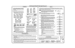
Use the Sony Manual that came with the projector for the procedure for
removing the circuit board and resetting the switch. A simple illustration is also
included in the figure on the previous page.
Frequencies above 48 kHz (see previous illustration)
For a better quality picture at higher frequencies, don’t use the 14-pin cable for
the RGB signals; use the BNC connectors on the projector instead.
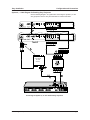
See note at the top of this page and use the diagram on the previous page for
the following steps.
7a. The Sony Adapter (SY COM) has one 9-pin male connector that
accommodates the Comm Extension cable. Do NOT use the eight BNC
connectors on the adapter. Only the control signals will go through the Comm
Adapter. Plug the single 14-pin connector from the adapter into the connector
marked “Remote 1” on the Sony connector panel.
8a. Plug the 15-pin HD connector of the Projector Communications Extension cable
(shown as CC 50') into the PJ Comm port on the System 4xi. The other end has
a 9-pin female connector. Plug this end into the 9-pin male D connector on the
SY COM adapter and secure the screws.
9a. Plug the BNC connectors on one end of the RGBS cable onto the System 4xi
output and those on the other end onto the matching BNCs on the Sony
projector.
Stacking Sony Projectors (see following illustration)
Sony projectors are sometimes “stacked” to provide increased brightness. This
technique uses two projectors which display the same image at the same time
on the same screen. To supply RGBS signals to two projectors, an Analog
Distribution Amplifier is required, as well as three, Hi-Res 5-BNC cables.
If the System 4xi is not already setup for Sony, follow steps 1 through 6 on the
previous pages. To parallel-connect the projectors, choose which projector will
be #1 and which will be #2, and continue.
See note at the top of this page and use the following illustration for the following
steps.
7b. Connect the Communications Extension cable from the System 4xi to the
adapter.
8b. Connect the SY COM adapter as shown on the following page. Do NOT use the
eight BNC connectors for the video signals; only the control signals will go
through the adapter. Plug the round, 14-pin connector into the projector
designated as “Projector #1” and turn the collar to secure it in place.
9b. Connect the color-coded, Hi-Res RGBS cable from the BNC outputs of the
System 4 to the input of the ADA.
10b. Connect the first output of the ADA to the BNC input of Projector #1.
Connect the second output of the ADA to the BNC input of Projector #2.
11b. Connect a “mini-phone” control cable from the “Controls Out” jack on
Projector #1 to the “Controls In” jack on Projector #2.
__________ This setup allows any commands, such as remote control, etc., received by
Projector #1 to be passed to Projector #2.
Extron • System 4xi Switcher Series • User’s Manual • P/N 68-408-02 Rev. A
Page 3