Transcript
MGP 464 and MGP 464W Multi-Graphic Processors
Installation
1. Install the four rubber feet on the bottom of the MGP, or rack
mount the unit with the provided brackets. For rack mounting,
remove the self-adhesive rubber feet if they have been attached.
(Refer to chapter 2, “Installation and Operation,” in your MGP
user’s manual.)
5
5
1
RGBHV
Video
R/R-Y
R/R-Y
G/Y
VID
H/HV
1
RGBS or
RGBcvS
Video
G/Y
VID
RGsB or
Component
Video
G/Y
VID
H/HV
Analog is not available
on this DVI-I connector.
V
1
B/C
B-Y
S-video
B/C
B-Y
V
V
1 Composite
G
/Y
H
/HV
V
B
/B-Y
1
R
/R-Y
G
/Y
H/
HV
V
2
B
/B-Y
Video
R/R-Y
R/R-Y
RGBHV
•
G/Y
VID
H/HV
G/Y
VID
H/HV
B/C
B-Y
V
B/C
B-Y
V
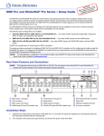
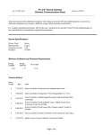
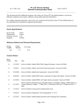
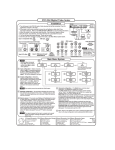
DVI-I inputs 1, 2, 3, and 4 — DVI (MGP 464 DI and MGP 464W DI
models only)
INPUT 1-DVI-D
INPUT 2-DVI-D
INPUT 3-DVI-D
INPUT 4-DVI-D
Analog is not available on these DVI-I connectors.
•
Virtual inputs 5–19 — (Non-WindoWall models only) Component
video, S-video, or composite video (configurable via Windows®based control software, SIS™ commands, or Web pages only).
See the illustration at top right.
In each column, inputs can be connected as follows:
❍
Three composite video inputs
❍
One interlaced component video input. (Connects to all
three BNCs in the column.)
❍
One S-video input and one composite video input
The S-video must always be connected to the top
two BNCs (Y on top, C second). A composite video
input can be connected to the bottom BNC.
G
/Y
H
/HV
V
B
/B-Y
RGsB
•
3
RGBS
R
/R-Y
R
/R-Y
G
/Y
H
/HV
V
B
/B-Y
HD YUV Component Video
DVI output
4
DVI OUTPUT
Analog is not available
on this DVI-I connector.
5. If the MGP 464 will be connected to a computer or to a host
controller for remote control, connect the host’s RS-232 cable
to the MGP’s 9-pin RS-232/422 D connector; and/or use an
RJ-45 network cable to connect the MGP’s LAN port to a
network. Refer to your MGP user’s manual for instructions.
6. Plug the MGP and the input and output devices into a grounded
AC source, and turn on the input and output devices.
5
6
7
Multi-Graphic
Processor
7. Non-WindoWall models: Use the LCD menu screens (see
“Menus,” at right), SIS commands, the MGP 464 Web pages, or
the Windows-based control software to configure the MGP. Refer
to chapters 3, 4, and 5 of the MGP 464 User’s Manual.
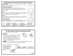
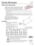
The MGP 464 front panel (non-WindoWall models only) contains the following sets of buttons that let you control and configure the processor.
Freeze — Freeze the input in the currently selected window. To unfreeze the input, press the button again.
•
RGB/HD/Video Inputs (1–4) — Select fully configurable inputs 1–4. On the MGP 464 DI, these buttons can also select the four DVI
inputs. To mute (turn off) the input in a window, press its button twice (or once, if the button is already lit). The button flashes while
the input is muted.
•
Virtual Video Inputs (5–19) — Select inputs 5–19. These inputs can be configured to accept S-video, composite video, or standard
definition component video only.
•
Window selection — Select a window to freeze/unfreeze, mute/unmute, select an input, or to adjust using Picture Control buttons.
•
Preset Recall/Save and Enter — Save the current configuration settings (preset) to memory, or recall a stored preset. 128 presets are
available. To save the current settings as a preset, press and hold the Preset Recall/Save button for 2 seconds. Rotate either Adjust
knob to select a preset number, then press Enter. To recall a preset, press and release the Preset Recall/Save button. Rotate either
Adjust knob to select a preset to recall, then press Enter.
Picture control — Adjust window and image size, brightness, range of dark and light values (contrast), detail (sharpness), position,
color, tint, and zoom (magnify/reduce). Use the horizontal ([) and vertical ({) Adjust knobs to adjust the picture settings shown on
the left and right sides of the LCD screen, respectively.
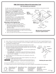
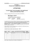
Input Configuration — Press Next to select the submenus for video signal format
(e.g., RGB), Film Mode, Vertical Start, Horizontal Start, Pixel Phases for windows
1–4, Total Pixels, Active Pixels, and Active Lines. From each submenu, rotate the
horizontal Adjust knob ([) to select the input to configure (only inputs 1–4 can
be configured via the front panel), and the vertical Adjust knob ({) to select a
value or parameter to apply to the selected input.
Output Configuration — Press Next to select the submenus for Resolution and
Refresh Rate, Output Type (e.g., RGBHV), and Sync Polarity. Rotate the
horizontal knob ([) to select the required output resolution, and the vertical
Adjust ({) knob to select the refresh rate. Turn either Adjust knob to select the
output video type: RGBHV, RGBS, RGsB, YUV Bi-level, or YUV Tri-level. Use
either Adjust knob to select positive or negative sync polarity for the horizontal
and vertical sync.
Window Configuration — Press Next to select submenus for Window Priority
(displayed in front or in back), Border Color for windows 1–4, Window Effect
(transition effect while muting; e.g., Dissolve or Cut), and Effect Duration. Rotate
either Adjust knob to select options from each submenu.
Background Capture — Press Next to save the currently displayed image as
background for the windows. Turn either Adjust knob to select a name for the new
background file. Press Next to save the image, then Detail to confirm. To recall an
existing background image file to display, press Next twice.
Default
Cycle
2 sec.
8
MENU
Auto
Image
1
2
3
Blue Mode: Use either Adjust knob to enable or disable Blue Mode, which
allows only sync and blue video signals to be sent to the display, for setup
purposes.
•
Test Patterns: Rotate either Adjust knob to select a test pattern to adjust the
display.
•
Internal Temperature: View the unit’s current internal temperature in degrees
Fahrenheit and Celsius.
•
Factory Default: Press Detail to reset the unit to the default settings from the
factory.
Input
Configuration
20 sec.
Output
Configuration
20 sec.
MENU
4
Window
Configuration
20 sec.
MENU
5
Background
Capture
20 sec.
MENU
Advanced configuration — Press Next to select the following submenus:
Background Color: Rotate either Adjust knob to select a background color for
the output screen.
20 sec.
MENU
MENU
Communication/IP Configuration — Press Next to view the serial communication
(RS-232/422) port configuration and the MGP’s IP address.
•
WindoWall models: Use the WindoWall Console software to
configure the MGP. Refer to chapter 3 of the MGP 464W User’s
Manual.
•
Auto Image — Automatically sizes, centers, and optimizes the image to the scaled
output rate, filling the window. Rotate either Adjust knob to select a window on
which the Auto Image function will be performed, or to select na to specify that
Auto Image will not be performed.
•
Front Panel Buttons
•
2 sec.
DVI BACKGROUND
BNCs for RGBHV, RGBS, RGsB, or YUV-HD component
video output
R
/R-Y
Extron
MGP 464
V1.00
Power
on
To return to the default cycle, let the MGP 464 remain idle until the selected
screen times out (about 20 seconds); or press the Menu button repeatedly until
the Exit Menu appears, then press the Next button.
4. Attach one or two displays or other output devices to the
MGP's output connectors.
•
B/C
B-Y
VID
R-Y
DVI Background input — DVI for live background video only
R/R-Y
H/HV
7
VID
R-Y
VID
R-Y
•
VID
B-Y
C
7
7
If you press the Menu button while a submenu is active, the display returns
to the beginning of that menu, and the menu’s title (the Main menu item) is
displayed. For example, if you press Menu while Resolution/Refresh (a
submenu of the Output Configuration menu) is active, the display returns
to the Output Configuration screen.
6
VID
B-Y
C
VID
B-Y
C
RGB/HD/VIDEO INPUTS 1, 2, 3, and 4 — RGB, component
video, S-video, or composite video (fully configurable)
1
VID
Y
6
6
The MGP 464’s menu system (non-WindoWall models only) enables you to configure the MGP by pressing buttons on the front panel.
Press the Menu button to move through the menus listed below. From the displayed menu, press the Next button to move through its
submenus. For each submenu, rotate the horizontal ([) and vertical ({) Adjust knobs to make selections. Refer to your MGP 464 User’s
Manual for further information on MGP menus and control buttons.
5
VID
Y
VID
Y
3. Connect the input sources to the MGP's BNC and/or DVI input
connectors. The inputs can accept the following signal types:
S-video and
Composite
Component
Composite
2. Turn off power to the input and output devices and remove the
power cords from them.
•
Menus
6
Comm. / IP
Configuration
20 sec.
MENU
7
Advanced
Configuration
20 sec.
MENU
MENU
8
Exit Menu
Press Next
20 sec.
NEXT
Exit Menu — Press Next to exit the menu system and return to the default cycle.
Executive Mode
LISTED
®
US 1T23
I.T.E.
To prevent accidental changes to settings, executive mode locks all panel controls except Freeze, input selection,
Preset Recall/Save, and the RS-232/422 and Ethernet ports. To enable/disable executive mode, press the
Window/Image Size and Window/Image Position buttons simultaneously, and hold them down for 2 seconds
(non-WindoWall models only).
N15779
www.extron.com
Extron Electronics, USA
1230 South Lewis Street
Anaheim, CA 92805
800.633.9876 714.491.1500
FAX 714.491.1517
Extron Electronics, Europe
Beeldschermweg 6C
3821 AH Amersfoort, The Netherlands
+800.3987.6673 +31.33.453.4040
FAX +31.33.453.4050
Extron Electronics, Asia
135 Joo Seng Rd. #04-01
PM Industrial Bldg., Singapore 368363
+800.7339.8766 +65.6383.4400
FAX +65.6383.4664
Extron Electronics, Japan
Kyodo Building, 16 Ichibancho
33-1390-01
Chiyoda-ku, Tokyo 102-0082
Rev B
Japan
06 08
+81.3.3511.7655 FAX +81.3.3511.7656