1
Technical
Information
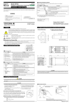
UT130, UT150/UT152/UT155
Temperature Controller
TI 05C01E02-01E
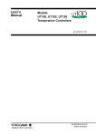
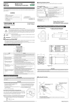
Easy-to-use Controllers for Operators
Compact Body
Full Functions
48 x 48mm
Compact Body
Large Display
48 x 48mm
Simple Operation
Less Space
48 x 96mm
Simple Operation
Large Display
96 x 96mm
Features
• Large display
• Simple operation
• Available 24V AC/DC power supply
• Dynamic Auto Tune control
• Full alarm functions
• Retransmission outputs
•Timer function
• RUN / STOP switching
TI 05C01E02-01E
© Copyright Oct. 2001
1st Edition: Oct. 2001
Blank Page
<Toc> <Ind> <Rev>
i
<Introduction>
INTRODUCTION
The UT100 Series contr oller s are the contr oller s mainl y for temperature contr ol.
The UT100 Series contr oller s are de veloped using the ne west tec hnology based on the
Yokogawa Group’ s experience f or contr ol f or y ears and results cultiv ated fr om man y
applications.
■ Document Structure
This document describes the functions of UT100 Series controllers.
The document consists of the following chapters.
Chapter 1: This c hapter e xplains what a temperature contr
oller is.
Chapter 2: This c hapter e xplains the model and suffix codes of the contr
information f or or dering.
oller and the
Chapter 3: This c hapter e xplains the P arameter Flo wchart and Parameter Lists of UT
100 Series contr oller s.
Chapter 4: This c hapter e xplains the basic operating pr
Series contr oller at fir st
ocedures when using a UT100
Chapter 5: This c hapter e xplains the applied operations not described in Chapter 4.
Chapter 6: This c hapter e xplains the basic functions of UT100 Series contr
oller s.
Chapter 7:This c hapter e xplains a tr oub leshooting f or err ors before/during operation.
Chapter 8:This c hapter e xplains the installation,
wiring and har dware specifications.
■ Intended Readers
This document is intended to the following personnel:
• Instrumentation engineers or electrical engineers planning to use a temperature
controller
• Instrumentation engineers or electrical engineers who would like to know the outline
of a temperature controller
■ Trademark Acknowledgements
• The compan y and pr oduct names ref erred to in this document are either trademarks
or registered trademarks of their respective holders.
TI 05C01E02-01E
1st Edition : Oct. 31, 2001-00
Blank Page
Toc-1
<Int> <Ind> <Rev>
UT130, UT150/UT152/UT155
Temperature Controller
TI 05C01E02-01E 1st Edition
CONTENTS
INTRODUCTION .................................................................................................... i
1. DESCRIPTION OF TEMPERATURE CONTROL ........................................... 1-1
2. INFORMATION TO ORDER A CONTROLLER .............................................. 2-1
2.1 Model and Suffix Codes ......................................................................................... 2-1
2.2 Mandatory Items to Specify ................................................................................... 2-5
2.3 Optional Suffix Codes to Specify ........................................................................... 2-5
2.4 Other Items to Specify ............................................................................................ 2-6
2.5 User’s Manual .......................................................................................................... 2-8
3. NAMES AND FUNCTIONS OF EACH PART / PARAMETER ......................... 3-1
3.1 UT130 Names and Functions of Each Part (Principles of Key Operation) ........... 3-1
3.2 UT130 Parameter Flowchart and Description ....................................................... 3-2
3.3 UT150/UT152/UT155Names and Functions of Each Part (Principles of Key Operation) ....3-6
3.4 UT150/UT152/UT155 Parameter Flowchart and Description ................................ 3-8
4. BASIC OPERATIONS .................................................................................... 4-1
4.1 Setting Measured Input Type and Scale (Setting First) ......................................... 4-1
4.2 Setting Control Action ............................................................................................ 4-5
4.2.1 Selecting a Control Mode (Dynamic Auto Tune Control / PID Control / ON-OFF Control) .... 4-5
4.2.2 Switching Direct / Reverse Action ............................................................ 4-6
4.2.3 Setting Cycle Time (Control Output Renewal Period) ............................... 4-8
4.3 Setting Target Setpoint (SP) ................................................................................... 4-9
4.3.1 Setting Target Setpoint (SP) of UT130 ..................................................... 4-9
4.3.2 Setting Target Setpoint (SP) of UT150/UT152/UT155 ............................ 4-10
4.4 Setting Alarms ...................................................................................................... 4-12
4.4.1 Setting Alarm Type and Hysteresis ........................................................ 4-12
4.4.2 Setting Alarm Setpoint ........................................................................... 4-16
4.4.3 Heater Disconnection Alarm Function ................................................... 4-17
TI 05C01E02-01E
1st Edition : Oct. 31, 2001-00
Toc-2
<Int> <Ind> <Rev>
5. APPLIED OPERATIONS ............................................................................... 5-1
5.1 Changing Measured Input Type and Scale ............................................................ 5-1
5.2 Correcting Measured Input Value .......................................................................... 5-1
5.3 Reducing Input Variations ...................................................................................... 5-2
5.4 Setting Maximum and Minimum Values of Target Setpoint Range ....................... 5-2
5.5 Setting Target Sepoint Ramp Rate (Rate-of-Change) ........................................... 5-3
5.6 Using Two Target Setpoints .................................................................................... 5-4
5.7 Retransmission of Measured Input Value in Current Signal ................................ 5-4
5.8 Switching RUN/ STOP ............................................................................................ 5-5
5.9 Using Timer Function (Turning on External Contact Outputs after the Set Time Elapses) ....... 5-6
5.10 Setting Key Lock ................................................................................................... 5-7
5.11 Selecting Priority of PV/SP Display at Power on (for UT130 Only) ..................... 5-8
5.12 Performing Heating/Cooling Control ................................................................... 5-8
5.13 Communicating with PC or PLC .......................................................................... 5-9
6. DESCRIPTION OF EACH FUNCTION ........................................................... 6-1
6.1 ON/OFF Control ...................................................................................................... 6-1
6.1.1 ON/OFF Control and Hysteresis .............................................................. 6-1
6.1.2 ON/OFF Control Application Example ..................................................... 6-1
6.2 Proportional (P) Action........................................................................................... 6-2
6.2.1 Differences between ON/OFF Action and Proportional Action ................. 6-2
6.2.2 Proportional Band (P) Details .................................................................. 6-2
6.2.3 Tuning the Proportional Band ................................................................... 6-3
6.3 Integral (I) Action .................................................................................................... 6-4
6.3.1 Integral Time (I) ....................................................................................... 6-4
6.3.2 Tuning the Integral Time ........................................................................... 6-4
6.4 Derivative (D) Action ............................................................................................... 6-5
6.4.1 Derivative Time (D) .................................................................................. 6-5
6.4.2 Tuning the Derivative Time ....................................................................... 6-5
6.5 Dynamic Auto Tune Control and PID Control ........................................................ 6-6
6.5.1 Dynamic Auto Tune Control ..................................................................... 6-6
6.5.2 Manually Tuning PID Constants ............................................................... 6-7
6.5.3 PID Auto-Tuning ...................................................................................... 6-7
6.6 Control Output ........................................................................................................ 6-8
6.6.1 Time Proportional PID Output (Relay Output / Voltage Pulse Output) ....... 6-8
6.6.2 Cycle Time .............................................................................................. 6-8
6.6.3 Continuous PID Output (4 to 20mA DC) ................................................... 6-9
6.7 Overshoot Suppressing Function “SUPER” ....................................................... 6-10
6.7.1 “SUPER” Operating Principles ............................................................... 6-10
6.7.2 Effects of “SUPER” ................................................................................ 6-10
TI 05C01E02-01E
1st Edition : Oct. 31, 2001-00
Toc-3
<Int> <Ind> <Rev>
7. TROUBLESHOOTING ................................................................................... 8-1
8. INSTALLATION AND HARDWARE SPECIFICATIONS ................................. 8-1
8.1 Installation .............................................................................................................. 8-1
8.2 Panel Cutout Dimensions and External Dimensions ........................................... 8-3
8.3 Wiring ...................................................................................................................... 8-7
8.4 Hardware Specifications ...................................................................................... 8-12
TI 05C01E02-01E
1st Edition : Oct. 31, 2001-00
Blank Page
1-1
<Toc> <Ind>
1. DESCRIPTION OF TEMPERATURE CONTROL
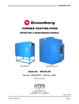
■ Temperature Controller
The temperature controller is used to keep the fixed temperature of such as a furnace
(controlled object). In general, the temperature controller has temperature indicating
display and setpoint setting display, generates a control signal according to the difference between a indicating value (measured temperature value) and SP to finally make
the temperature agree with SP.
Sensors such as thermocouple (TC) or RTD can be connected for measuring a temperature. And output types such as relay output or current output (4 to 20mA) are
prepared according to the operating terminal (heater, valve, and the like) that actually
controls a temperature.
Measured input
•Thermocouple
• RTD
Measuring
object
Work
Control output
• Relay
• Voltage pulse
• Current
Operating
device
• SSR
• Power regulator
Heater
Controlled object
TI 05C01E02-01E
1st Edition : Oct. 31, 2001-00
1-2
<Toc> <Ind>
■ Types of Temperature Control Action
ON/OFF action is the simplest action among the control actions. ON/OFF action of the
internal thermostat keeps the optimum temperature. But the temperature control
output fluctuates in the fixed cycle with ON/OFF action. If this temperature cycle
causes a problem, the control action that changes the output in proportion to the deviation (the difference between the target setpoint and present value) can give a better
control performance. Thus the control action that moves the function part in proportion
to the deviation is referred to as a proportional action (P action). But a steady-state
deviation (offset) is inherently unavoidable with proportional action alone. Though the
manual reset can remove the offset, the same thing can be done using the control
action together with the Integral action (I action) that will integrate the deviation as long
as the deviation exists. This combination is referred to as a proportional-plus-integral
action (PI action). It is the popular control method among the process control actions.
On the other hand, the derivative action (D action) is the action that changes the output
in proportion to the rate-of-change of deviation. Since the output of derivative action
depends on not the amount of deviation but its rate-of-change, the larger the rate-ofchange is, the more intensive corrective action the controller takes to correct the process response in advance. Setting each optimum value with the PID action consisted
of these three actions enables a stable control quickly.
■ Dynamic Auto Tune Control
The Dynamic Auto Tune Control is the function to automatically determine the optimum
PID constants for continuing a good control when the controller is turned on or the
control conditions are unstable. This control method is gentle to the controlled object
itself because a disturbance needs not to be set forcibly like Auto tuning.
In Dynamic Auto Tune Control, the controller automatically monitors the behavior and
determines the optimum PID constants when (1) at power on, (2) the output travels up
to 100% or down to 0% and remains there after changing a setpoint, (3) process begins
oscillating by disturbance and the like. The principle of Dynamic Auto Tune Control can
be relied on because it is based on Geglar/Nichols’s control method.
Refer to “6.5.1 Dynamic Auto Tune Control” on Page 6-6.
TI 05C01E02-01E
1st Edition : Oct. 31, 2001-00
2-1
<Toc> <Ind>
2. INFORMATION TO ORDER A CONTROLLER
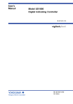
2.1 Model and Suffix Codes
The models and suffix codes of UT130, UT150/UT152/UT155 standard types are as
follows:
Type
External Appearance
Options
Without alarm
UT130
48x48x100mm
3-digit display
Number of SP: 2
Without
other options
With 2 alarms
With communication
Without alarm
Without
other options
UT150
48x48x100mm
4-digit display
Number of SP: 2
With
retransmission
output
With 2 alarms
With external
contact input
With communication
With retransmission
output/external
contact input
Without alarm
Without
other options
UT152
48x96x100mm
4-digit display
Number of SP: 2
With
retransmission
output
With 2 alarms
With external
contact input
With communication
With retransmission
output/external
contact input
Without alarm
Without
other options
UT155
96x96x100mm
4-digit display
Number of SP: 2
With
retransmission
output
With 2 alarms
With external
contact input
With communication
With retransmission
output/external
contact input
Output
Standard Type Model
Relay output
Voltage pulse output
Relay output
Voltage pulse output
Relay output
Voltage pulse output
UT130-RN
UT130-VN
UT130-RN/AL
UT130-VN/AL
UT130-RN/AL/RS
UT130-VN/AL/RS
Relay output
Voltage pulse output
Current output
Relay output
Voltage pulse output
Current output
Relay output
Voltage pulse output
Current output
Relay output
Voltage pulse output
Current output
Relay output
Voltage pulse output
Current output
Relay output
Voltage pulse output
Current output
UT150-RN
UT150-VN
UT150-AN
UT150-RN/AL
UT150-VN/AL
UT150-AN/AL
UT150-RN/AL/RET
UT150-VN/AL/RET
UT150-AN/AL/RET
UT150-RN/AL/EX
UT150-VN/AL/EX
UT150-AN/AL/EX
UT150-RN/AL/RS
UT150-VN/AL/RS
UT150-AN/AL/RS
UT150-RN/AL/RET/EX
UT150-VN/AL/RET/EX
UT150-AN/AL/RET/EX
Relay output
Voltage pulse output
Current output
Relay output
Voltage pulse output
Current output
Relay output
Voltage pulse output
Current output
Relay output
Voltage pulse output
Current output
Relay output
Voltage pulse output
Current output
Relay output
Voltage pulse output
Current output
UT152-RN
UT152-VN
UT152-AN
UT152-RN/AL
UT152-VN/AL
UT152-AN/AL
UT152-RN/AL/RET
UT152-VN/AL/RET
UT152-AN/AL/RET
UT152-RN/AL/EX
UT152-VN/AL/EX
UT152-AN/AL/EX
UT152-RN/AL/RS
UT152-VN/AL/RS
UT152-AN/AL/RS
UT152-RN/AL/RET/EX
UT152-VN/AL/RET/EX
UT152-AN/AL/RET/EX
Relay output
Voltage pulse output
Current output
Relay output
Voltage pulse output
Current output
Relay output
Voltage pulse output
Current output
Relay output
Voltage pulse output
Current output
Relay output
Voltage pulse output
Current output
Relay output
Voltage pulse output
Current output
UT155-RN
UT155-VN
UT155-AN
UT155-RN/AL
UT155-VN/AL
UT155-AN/AL
UT155-RN/AL/RET
UT155-VN/AL/RET
UT155-AN/AL/RET
UT155-RN/AL/EX
UT155-VN/AL/EX
UT155-AN/AL/EX
UT155-RN/AL/RS
UT155-VN/AL/RS
UT155-AN/AL/RS
UT155-RN/AL/RET/EX
UT155-VN/AL/RET/EX
UT155-AN/AL/RET/EX
Note 1: Heating/cooling control type is available in addition to the standard type described above. Refer to the following pages.
Note 2: For options, the combinations other than those mentioned above are available. Refer to the following pages.
TI 05C01E02-01E
1st Edition : Oct. 31, 2001-00
2-2
<Toc> <Ind>
■ Standard type
● UT130 Standard Type: Model and Suffix Codes
Model and Suffix Codes
Model
Suffix codes
UT130
Description
Temperature controller (48 x 48 x 100mm)
Relay output (time-proportional PID or on/off control)
-R
-V
Control
output
Fixed
Voltage pulse output (time-proportional PID control)
N
Fixed
/AL
/HBA
/RS
/V24
Options
Alarm outputs (2 points) (Note1)
Heater disconnection alarm (includes the function of " /AL" option) (Note 1)
Communication function (Note 2)
Power Supply 24V DC / 24V AC
Check the package contents against the list below.
• Temperature controller (of ordered model) . . . . . . 1
• Mounting bracket . . . . . . . . . . . . . . . . . . . . . . . . . . . . . . . 1
• User’s Manual (IM 05C01E02-01E) . . . . . . . . . . . . . 1
Note 1: The "/AL" and "/HBA" options cannot be specified at the same time. The "/HBA" option includes the function
of "/AL" option.
Note 2: When specifying the "/RS" option, be sure to order the required number of copies of the Communication
Functions User’s Manual (IM05C01E12-10E) separately. (See Page 2-8.)
● UT150 Standard Type: Model and Suffix Codes
Model and Suffix Codes
Model Suffix Codes
UT150
Description
Temperature controller (48 x 48 x 100 mm)
-R
-V
-A
Control
output
Fixed
Relay output (time-proportional PID or on/off control)
Voltage pulse output (time-proportional PID control)
4 to 20mA output ( current PID) (Note1)
Fixed
N
/AL
/HBA
/EX
/RET
/RS
/V24
Option
Alarm outputs (2 points) (Note2)
Heater disconnection alarm (includes the function of " /AL" option) (Notes 2 and 3)
SP1/SP2 switching, starting of timer, and RUN/STOP switching byexternal contacts (Notes 4 and 5)
PV retransmission output in 4 to 20mA (Note 3)
Communication function (Notes 4 and 6)
Power Supply 24V DC / 24VAC
UT150 Table of Option Combination
/AL
/AL
/HBA
/HBA
N/A
N/A
/RET
/RS
/V24
A
A
A
A
N/A
N/A
A
A
A
N/A
A
A
A
/EX
/EX
A
A
/RET
A
N/A
A
/RS
A
A
N/A
A
/V24
A
A
A
A
A
A
Check the package contents against the list below.
• Temperature controller (of ordered model) . . . . . . 1
• Mounting bracket . . . . . . . . . . . . . . . . . . . . . . . . . . . . . . . 1
• User’s Manual (IM 05C01E12-01E) . . . . . . . . . . . . . 1
A : Available
N/A : Not available
Note 1: The " /HBA" option cannot be specified when selecting "4 to 20mA output" as a control output type.
Note 2: The "/AL" and "/HBA" options cannot be specified at the same time. The "/HBA" option includes the function
of "/AL" option.
Note 3: The "/HBA" and "/RET" options cannot be specified at the same time.
Note 4: "/EX" and "/RS" options cannot be specified at the same time.
Note 5: Two points of external contact inputs are available. Select 2 functions among SP1/SP2 switching, starting of
timer, and RUN.STOP switching.
Note 6: When specifying the "/RS" option, be sure to order the required number of copies of the Communication
Functions User s Manual (IM05C01E12-10E) separately. (See Page 2-8)
TI 05C01E02-01E
1st Edition : Oct. 31, 2001-00
2-3
<Toc> <Ind>
● UT152 / UT155 Standard Type: Model and Suffix Codes
Model and Suffix Codes
Model
Suffix codes
Control
output
Fixed
Description
Temperature controller ( 48 x 96 x 100mm )
Temperature controller ( 96 x 96 x 100mm )
Relay output (time-proportional PID or on/off control)
Voltage pulse output (time-proportional PID control)
4 to 20mA output ( current PID) (Note1)
UT152
UT155
-R
-V
-A
N
Fixed
/AL
/HBA
/EX
/RET
/RS
/V24
Option
Alarm outputs (2 points) (Note2)
Heater disconnection alarm (includes the function of "/AL" option) (Notes 2 and 3)
SP1/SP2 switching, starting of timer, and RUN/STOP switching by external contacts (Notes 4 and 5)
PV retransmission output in 4 to 20mA (Note 3)
Communication function (Notes 4 and 5)
Power Supply 24V DC / 24VAC
• Check the package contents against the list below.
• Temperature controller (of ordered model) . . . . . . 1
• Mounting bracket . . . . . . . . . . . . . . . . . . . . . . . . . . . . . . . 1
• User’s Manual (IM 05C01E12-01E) . . . . . . . . . . . . . 1
Note 1: The " /HBA" option cannot be specified when selecting "4 to 20mA output" as a control output type.
Note 2: The "/AL" and "/HBA" options cannot be specified at the same time. The "/HBA" option includes the function
of "/AL" option.
Note 3: Two points of external contact inputs are available. Select 2 functions among SP1/SP2 switching, starting of
timer, and RUN/STOP switching.
Note 4: When specifying the "/RS" option, be sure to order the required number of copies of the Communication
Functions User’s Manual (IM 05C01E12-10E) separately. (See Page 2-8)
■ Heating/Cooling Type
● UT130 Heating/Cooling Type: Model and Suffix Codes
Model and Suffix Codes
Model
Suffix codes
UT130
Control
-R
output
for heating -V
Control
R
output
V
for cooling
Option
Description
Temperature controller (48 x 48 x 100mm)
Relay output (time-proportional PID or on/off control)
Voltage pulse output (time-proportional PID control)
Relay output (time-proportional PID or on/off control)
Voltage pulse output (time-proportional PID control)
/AL
/HBA
/RS
/V24
Alarm outputs (2 points) (Note1)
Heater disconnection alarm (includes the function of "/AL" option) (Notes 1 and 2)
Communication function (Notes 2 and 3)
Power Supply 24V DC / 24V AC
Check the package contents against the list below.
• Temperature controller (of ordered model) . . . . . . 1
• Mounting bracket . . . . . . . . . . . . . . . . . . . . . . . . . . . . . . . 1
• User’s Manual (IM 05C01E02-01E) . . . . . . . . . . . . . 1
Note 1: The "/AL" and "/HBA" options cannot be specified at the same time. The "/HBA" option includes the function
of "/AL" option.
Note 2: For heating/cooling type, the "/HBA" and "/RS" options cannot be specified at the same time.
Note 3: When specifying the "/RS" option, be sure to order the required number of copies of the Communication
Functions User’s Manual (IM05C01E12-10E) separately. (See Page 2-8)
TI 05C01E02-01E
1st Edition : Oct. 31, 2001-00
2-4
<Toc> <Ind>
● UT150 Heating/Cooling Type: Model and Suffix Codes
Model and Suffix Codes
Model
Suffix codes
UT150
Description
Temperature controller (48 x 48 x 100mm)
Control
-R
output
-V
for heating -A
Control
R
output
V
for cooling
A
Option
Relay output (time-proportional PID or on/off control)
Voltage pulse output (time-proportional PID control)
4 to 20mA output ( current PID) (Note1)
Relay output (time-proportional PID or on/off control)
Voltage pulse output (time-proportional PID control)
4 to 20mA output ( current PID) (Note1)
Alarm outputs (2 points) (Note2)
/AL
/HBA Heater disconnection alarm (includes the function of " /AL" option) (Notes 2 and 3)
SP1/SP2 switching, starting of timer, and RUN/STOP switching byexternal contacts (Notes 3 and 4)
/EX
/RS PV retransmission output in 4 to 20mA
/V24 Power Supply 24V DC / 24VAC
UT150 Heating/cooling Type Table of Option Combination
/AL
N/A
/AL
/HBA
/HBA
N/A
/EX
/RS
/V24
A
N/A
A
N/A
A
/EX
A
N/A
/RS
A
N/A
N/A
/V24
A
A
A
N/A
A
A
A
A
Check the package contents against the list below.
• Temperature controller (of ordered model) . . . . . . 1
• Mounting bracket . . . . . . . . . . . . . . . . . . . . . . . . . . . . . . . 1
• User’s Manual (IM 05C01E12-01E) . . . . . . . . . . . . . 1
A : Available
N/A : Not available
Note 1: The " /HBA" option cannot be specified when selecting "4 to 20mA output" as a control output type.
Note 2: The "/AL" and "/HBA" options cannot be specified at the same time. The "/HBA" option includes the function
of "/AL" option.
Note 3: The "/HBA", "/EX" and "/RS" options cannot be specified at the same time.
Note 4: Two points of external contact inputs are available. Select 2 functions among SP1/SP2 switching, starting of
timer, and RUN/STOP switching.
Note 5: When specifying the "/RS" option, be sure to order the required number of copies of the Communication
Functions User’s Manual (IM05C01E12-10E) separately. (See Page2-8)
● UT152 / UT155 Heating/Cooling Type: Model and Suffix Codes
Model and Suffix Codes
Model
UT152
UT155
Suffix codes
Description
Temperature controller ( 48 x 96 x 100mm )
Temperature controller ( 96 x 96 x 100mm )
-R
Control
Relay output (time-proportional PID or on/off control)
output
-V
Voltage pulse output (time-proportional PID control)
for heating -A
4 to 20mA output ( current PID) (Note1)
R
Relay output (time-proportional PID or on/off control)
Control
output
V
Voltage pulse output (time-proportional PID control)
for cooling
A
4 to 20mA output ( current PID) (Note1)
Alarm outputs (2 points) (Note2)
/AL
/HBA Heater disconnection alarm (includes the function of "/AL" option) (Note 2)
Option
SP1/SP2 switching, starting of timer, and RUN/STOP switching by external contacts (Note 3)
/EX
/RS Communication function (Note 4)
/V24 Power Supply 24V DC / 24V AC
Check the package contents against the list below.
• Temperature controller (of ordered model) . . . . . . 1
• Mounting bracket . . . . . . . . . . . . . . . . . . . . . . . . . . . . . . . 1
• User’s Manual (IM 05C01E12-01E) . . . . . . . . . . . . . 1
Note 1: The " /HBA" option cannot be specified when selecting "4 to 20mA output" as control output type.
Note 2: The "/AL" and "/HBA" options cannot be specified at the same time. The "/HBA" option includes the function
of "/AL" option.
Note 3: Two points of external contact inputs are available. Select 2 functions among SP1/SP2 switching, starting of
timer, and RUN/STOP switching.
Note 4: When specifying the "/RS" option, be sure to order the required number of copies of the Communication
Functions User’s Manual (IM05C01E12-10E) separately. (See Page 2-8)
TI 05C01E02-01E
1st Edition : Oct. 31, 2001-00
2-5
<Toc> <Ind>
2.2 Mandatory Items to Specify
Specify the following necessary items on ordering
● Specify the power supply voltage
When using 100 to 240V AC, no need to specify the item.
When using 24V AC/DC, specify the “/V24” option.
The frequency for both of them is 50/60Hz.
● Specify the control output
<Example 1>
Specify “ UT150-RN” for UT150 standard type with relay output.
<Example 2>
Specify “UT150-RV” for UT150 heating/cooling type with heating-side relay output and
cooling-side voltage pulse output.
2.3 Optional Suffix Codes to Specify
The following options are available. But some of them are not available according to
the model. See “2.1 Model and Suffix Codes” for combinations of options.
● When using one or two Alarms, specify the “ /AL “ option.
<Example> Model and Suffix Codes: UT130-RN/AL
● When using Heater Disconnection Alarm, specify the “/HBA” option. The
“/HBA” option includes the function of “/AL” option.
<Example> Model and Suffix Codes: UT150-RN/HBA
● When using Retransmission Output, specify the “ /RET” option.
<Example> Model and Suffix Codes: UT150-AN/RET
● When using two Target Setpoints, specify the “ /EX” option.
<Example> Model/Suffix Codes: UT150-RN/EX
● When using Timer Function, specify the “ /AL /EX” or “/HBA /EX” options.
<Example> Model/Suffix Codes: UT150-VN/AL/EX
● When using RUN/STOP Switching Function, specify the “/EX” option.
<Example> Model/Suffix Codes: UT150-RN/EX
● When using Communication Function, specify the “ /RS” option.
<Example> Model/Suffix Codes: UT150-RN/RS
TI 05C01E02-01E
1st Edition : Oct. 31, 2001-00
2-6
<Toc> <Ind>
2.4 Other Items to Specify
■ Quality Inspection Certificate (QIC) and Traceability
The Quality Inspection Certificate (QIC) of the product at shipping is prepared.
And the Traceability, which certificates that the measuring instruments and generator
used for the product inspection conforms to the inspection of national standards, is also
prepared.
● Quality Inspection Certificate(QIC)
Model: DOCTC
● Calibration certificate (traceability)
“Traceability declaration to the national standards” and “Explanation of the Yokogawa’s
internal system for traceability”
Model: Q62188-B
■ Auxiliary Equipment and Spare Parts
● 250Ω Resistor
When a measured input signal is 4 to 20mA DC, the temperature controllers (UT150/
UT152/UT155) receive it after converting to a 1 to 5V DC signal.
Model
X010-250-2
Description
Resistor with M3.5 crimp-on terminal lugs
Receiving 4-20mA DC Current
Signals with UT150
*When receiving 4-20mA DC current signals,
set the PV input type to 1-5V DC (range code "22")
Receiving 4-20mA DC Current
Signals with UT152/UT155
*When receiving 4-20mA DC current signals,
set the PV input type to 1-5V DC (range code "22")
12 +
7 +
250Ω
250Ω 4-20mA
8 —
Note: Connecting a 250‰ resistor to the terminals is optional.
Model: X010-250-2(resistor with M3.5 crimp-on terminal lugs)
4-20mA
13 —
Note: Connecting a 250‰ resistor to the terminals is optional.
Model: X010-250-2(resistor with M3.5 crimp-on terminal lugs)
● Heater Disconnection Sensor (for 1 to 80A)
The heater current sensor used here is the “CTL-6-S-H” or “CTL-12-S36-8” sensor of
U.R.D., Ltd.
This sensor is to be purchased by the users themselves.
Model: CTL-6-S-H or CTL-12-S36-8
TI 05C01E02-01E
1st Edition : Oct. 31, 2001-00
2-7
<Toc> <Ind>
● Terminal Cover
Model
Description
L4000FB
Terminal cover for models UT130 and UT150 (1 set)
T9115YE
Terminal cover for model UT152 (1 piece)
T9115YD
Terminal cover for model UT155 (1 piece)
● Mounting Bracket
Model
Description
L4000FA
Mounting bracket for models UT130 and UT150 (1 piece)
T9115NK
Mounting bracket for model UT152 (1 set)
T9115NL
Mounting bracket for model UT155 (1 set)
■ Measured Input Type, Scaling and Direct/Reverse Action can be Specified on Ordering
Measured input type, displayed scale at voltage input, and direct/reverse action for the
temperature controller can be specified on ordering.
Items to specify
Measured
input type
Description
Specify "1" to "7", "12", "13", and "15 to "19" for UT130.
Specify "1" to "23" for UT150/UT152/UT155.
If no input type is specified at the time of ordering, the temperaturecontroller
is shipped with the parameter set to OFF (unidentified).
In this case, set the input type on customer side.
See "4.1 Setting Measured Input Type and Scale (Setting First)" for details.
The displayed scale can be specified when specifying "20" to "23"
Scaling
for UT150/UT152/UT155. If no scaling is specified, the temperature controller
(at voltage input) is shipped with the parameter set to "0.1 to 100.0".
Direct/reverse Specify "1" for direct action. If no action is specified, the temperature
controller is shipped with the parameter set to "0" (reverse action).
action
TI 05C01E02-01E
1st Edition : Oct. 31, 2001-00
2-8
<Toc> <Ind>
2.5 User’s Manual
User’s Manuals in A-2 size and A-4 size are prepared.
User’s Manuals supplied along with the product is in A-2 size. Both Manuals in A-4 size
and A-2 size have the same contents except for their appearances.
When specifying the ”/RS” option, be sure to order the required number of copies of
Communication Functions User’s Manual separately.
A4-size Manual
The following User’s Manuals can be purchased separately.
● User’s Manual for UT130 (A4 size)
Document Number: IM05C01E02-41E
● User’s Manual for UT150/UT152/UT155 (A4 size)
Document Number: IM05C01E12-41E
● Communication Functions User’s Manual for UT130, UT150/UT152/UT155
(A4 size)
Document Number: IM05C01E12-10E
TI 05C01E02-01E
1st Edition : Oct. 31, 2001-00
3-1
<Toc> <Ind>
3. NAMES AND FUNCTIONS OF EACH PART
/ PARAMETER
3.1 UT130 Names and Functions of Each Part
(Principles of Key Operation)
SP display lamp (orange)
• Lit when SP is displayed or being changed.
• Flashes slowly (approx. once every second) when
a parameter code is displayed.
• Flashes fast when a parameter value is being changed.
Data display (red)
• In the operating display, either PV (measured value) or
SP (target setpoint) is indicated.
Which parameter takes precedence over the other
depends on the parameter "DSP" value.
• In the parameter setting display, either the parameter
codes or parameter value is indicated.
• If an error occurs, the error code is displayed.
Output (OUT) display lamps
(Left: orange; right: green)
Alarm 1 (AL1) / Alarm 2 (AL2) lamps (red)
AL1: Lit when the alarm 1 is activated.
AL2: Lit when the alarm 2 is activated.
SET /ENT key (data registering key)
• In the operating display, it switches between the PV (measured value)
and SP (target setpoint) displays.
• Registers the data value changed using the data change keys.
• Switches between operating displays or parameter setting display
sequentially.
• Pressing the key for 3 seconds or more in the operating display
retrieves the operating parameter setting display. You can transfer to
the setup parameter setting display form the operating parameter
setting display.
• Pressing the key for 3 seconds or more in either an operating or setup
parameter setting display transfers back to the operating display.
Lit while control output is being output.
Flashes according to the control output value during timeproportional output. (Flashes slowly when control output
value is small; flashes fast when control output value is large.)
• The left lamp lights up in orange during control output of
standard type.
• In heating/cooling control, the left lamp lights up in orange
when the heating-side output is active; while the right lamp
lights up in green when the cooling-side output is active.
Data change keys
• When PV is displayed in the operating display, a press of
the
or
key switches to the SP display.
• When a parameter code is displayed, pressing either key
once displays the parameter value (which can then be
changed).
• Changes SP and the parameter values.
• Pressing the
key decreases the data value and
pressing the
key increases it. Holding down the key
will gradually increase the speed of the change.
TI 05C01E02-01E
1st Edition : Oct. 31, 2001-00
3-2
<Toc> <Ind>
3.2 UT130 Parameter Flowchart and Description
A
NOTE
Power ON
When the measured input range code has
been already set, the operating display shown
below appears.
No
When IN appears, press the
key to display the measured input
range code you want to use, then
press the
key to register it.
After this operation, the controller
shows the operating display.
Yes
is displayed
?
A
Operating Display
Displays PV
Displays SP
* Refert to the Measured Input Ranges on
Page 4-1.
To switch between PV and SP,
press the
key.
SP (target setpoint) can be
changed in the operating display.
SP display lamp
is on.
The data (PV or SP) selected in "DSP" is
displayed at first. (Default: PV display)
Note
Press the
key
for at least 3 seconds.
(To operating parameter
setting display)
Press the
key
for at least 3 seconds.
(To operating display)
Note: If no key is pressed for a period of 2 minutes or more
while in the operating or setup parameter setting display,
the controller automatically returns to operating display.
Operating parameter setiing dispaly
A1
A2
HC
Press the
key to move
between items.
Displayed only for the "/AL" or "/HBA" option.
Not displayed when AL1, AL2 = OFF
Not displayed when AL1, AL2 = 21 or 22
Displayed only for the "/HBA" option and when AL1 = 25
CTL
CTL=SLF
(Dynamic Auto Tune)
Note
CTL=SLF is not
permitted for heating/
cooling type.
AT
P
I
D
MR
COL
CTL=PID
(PIDcontrol)
CTL=ONF
(on/off control)
Displayed when I = OFF
Displayed for heating/
cooling type
DB
Displayed for heating/cooling type
CT
) Displayed for time-proportional PID control
CTC
HYS
Displayed for time-proportional PID control
of heating/cooling type
FL
BS
LOC
LOC=
NOTE
When LOC=-1
When LOC= -1,
transfers to the
setup parameter
setting display
To Page 3-4
B
Set "-1" to enter the setup parameter setting
display. But if "LOC=1 or 2" is already set, the
parameter value can not be changed by setting
"LOC=-1" only. To change the parameter value,
set "LOC=0" at first (for disabling keylock),
then set "LOC=-1" once again.
TI 05C01E02-01E
1st Edition : Oct. 31, 2001-00
3-3
<Toc> <Ind>
(1) Target Setpoint (SP)
Code
(SP value display)
Name
Target
setpoint
Setting range and unit
Minimum value (SPL) to maximum value (SPH) of target setpoint
range
Unit: °C/°F
Default
User setting Reference page
SPL
P.4-9
Numbers in ( ) are the parmeter setpoints that apply
when the communication function is used.
Ex. OFF(0), ON(1)
(2) Operating Parameters: Parameters changed rather frequently during operation.
Code
Name
Setting range and unit
■ PV alarm Unit: °C/°F
Setting range: Minimum value to maximum value of
measured input range
Default
User setting Reference page
Max. value of
measured input
range (PV alarm)
A1
Alarm 1
setpoint
A2
Alarm 2
setpoint
HC
Heater disconnection HC is not a parameter to be set. The current value (0 to 80) of heater
disconnection detector is displayed. Unit: A (ampere)
current measured
Settings: When the display value is — — —, the heater current is not being measured.
value
■ Deviation alarm Unit: °C/°F
Setting range: —100 to 100% of measured input range
span
■ Heater disconnection alarm Unit: A (ampere)
Setting range: OFF(0), 1 to 80
(can be set for the alarm 1 setpoint only)
Min. value of
measured input
range (PV alarm)
P.4-12
P.4-16
P.4-17
Control mode
ONF(0): On/off control
SLF(2) : standard type;
PID(1): PID control
PID(1) : heating/cooling
SLF(2): Dynamic auto tune control (cannot be set for heating/cooling control)
type
P.4-5
P.6-1
P.6-6
Auto-tuning
OFF(0): Stop auto-tuning(AT)
ON(1): Start auto-tuning(AT)
OFF(0)
P.6-7
Proportional
band
1°C/°F to the temperature that corresponds to 100% of
the measured input range span
5% of measurd
input range span
P.6-2
Integral time
1 to 999 seconds;
OFF(0): no integral action
240 seconds
P.6-4
Derivative
time
1 to 999 seconds;
OFF(0): no derivative action
60 seconds
P.6-5
Manual reset
-19.9 to 99.9 % : Standard type
-100 to 100 % : Heating/cooling type
50.0% : Standard type;
0.0% :Heating/cooling
type
P.6-4
Cooling-side
gain
0.01 to 9.99 times
COL
1.00 time
P.5-8
DB
Dead band
CTL
AT
P
I
D
MR
■ PID control Unit: °C/°F
Setting range: —(proportional band setting) to +(proportional band setting) 0% of measured
■ On/off control Unit: °C/°F
input range span
Setting range: —50 to +50% of measured input range span
P.5-8
Hysteresis for 0°C/°F to the temperature that corresponds to 100% of
on/off control the measured input range span
0.5% of measured
input range span
P.6-1
Control
output cycle
time
1 to 240 seconds
30 seconds
CT
P.4-8
P.6-8
Cooling-side
control output
cycle time
1 to 240 seconds
30 seconds
CTC
P.6-8
PV input filter
OFF(0), 1 to 120 seconds
OFF(0)
P.5-2
PV input bias
—100 to 100% of measured input range span
0% of measured
input range span
P.5-1
Key lock
0: No key lock
1: Prevents operations from being changed except for the
changing of SP in the operating display
2: Prevents all parameter changing operations
—1: Set -1 to enter the setup parameter setting display.
But if LOC=1 or 2 is already set, the parameter
value can not be changed by setting LOC=-1 only. To
change the parameter value, set LOC=0 at first (for
disabling keylock), then set LOC=-1 once again.
0
P.5-7
HYS
FL
BS
LOC
TI 05C01E02-01E
1st Edition : Oct. 31, 2001-00
3-4
<Toc> <Ind>
NOTE
Changing certain setup parameter may automatically initialize the operating parameters. Therefore,
after you change the setup parameters, always check the operating parameter settings to find out if
appropriate values have been set for them. If the operating parameters have been initialized, set
them to their appropriate values.
To Page 3-2
Operating display
Note
Press the
key
for at least 3 seconds.
(To operating display)
From
Page 3-2
Note: If no key is pressed for a period of 2 minutes or more
while in the operating or setup parameter setting display,
the controller automatically returns to operating display.
Setup parameter setting display
B
Press the
key
to move between items.
IN
SPH
SPL
AL1
AL2
HY1
HY2
SC
DR
DSP
Displayed for the "/AL" or
"/HBA" option
Not displayed when "CTL"=ONF (on/off control)
Not displayed for heating/cooling type
PSL
ADR
BPS
PRI
STP
DLN
Displayed for the "/RS" option
TI 05C01E02-01E
1st Edition : Oct. 31, 2001-00
3-5
<Toc> <Ind>
Numbers in ( ) are the parmeter setpoints that apply
when the communication function is used.
Ex. OFF(0), ON(1)
(3) Setup Parameters: Parameters rarely changed in normal use after once having been set.
Code
Name
Setting range and unit
Default
IN
Measured
input type
1 to 7, 12, 13, 15 to 19, 31 to 37, 42, 43, 45 to 48 (See the OFF(0), or the
measured input range code list.)
OFF(0): No input
input range code
(If no input type is specified at the time of ordering, you must set the input type.) specified with
SPH
Maximum
value of target
setpoint range
(SPL+1°C) to the maximum value of measured input
range; Unit: °C/°F
SPL
Minimum value
of target
setpoint range
Minimum value of measured input range to (SPH—1°C)
Unit: °C/°F
Maximum value of
measured input
range
Alarm 1 type
Minimum value of
measured input
range
1
OFF(0), 1 to 22 (See the alarm function list.)
25 (for the heater disconnection alarm /HBA option only) (PV high limit alarm)
Alarm 2 type
OFF(0), 1 to 22 (See the alarm function list.)
2
(PV low limit alarm)
0 to 100% of measured input range span
Unit: °C/°F
0.5% of measured
input range span
ON(1): Uses the SUPER function
OFF(0): Does not use SUPER function
Note: Not displayed when on/off control
OFF(0)
User setting Reference page
P.4-1
P.5-1
P.5-2
AL1
AL2
HY1
Alarm 1
hysteresis
HY2
Alarm 2
hysteresis
SC
SUPER
function
P.6-10
Reverse action
Direct/reverse 0:
1: Direct action
action
Note: Not displayed for heating/cooling type
0
DR
Priority of
PV/SP
display
0: Displays PV
1: Displays target setpoint (SP)
0
DSP
PSL
Protocol
selection
0: PC-link communication
1: PC-link communication with sum check
2: Ladder communication
3: MODBUS in ASCII mode
4: MODBUS in RTU mode
ADR
Controller
address
P.4-6
P.
0
BPS
1 to 99
However, the number of controllers that can be connected
per host device is 31 at the maximum.
2.4(0): 2400 bps
4.8(1): 4800 bps
9.6(2): 9600 bps
EVN(1)
PRI
NON(0): Disabled
EVN(1): Even parity
ODD(2): Odd parity
1 or 2 bits
1 bit
7 or 8 bits
• 8 bits when ladder, MODBUS (RTU)
• 7 bits when MODBUS (ASCII)
8 bits
Baud rate
Parity
Stop bit
P.4-12
P.4-16
P.4-17
1
9.6(2)
P.5-9
STP
Data length
DLN
TI 05C01E02-01E
1st Edition : Oct. 31, 2001-00
3-6
<Toc> <Ind>
3.3 UT150/UT152/UT155Names and Functions of
Each Part (Principles of Key Operation)
SP2 lamp (green)
PV display (red)
Lit when SP2 is being used for control operation.
Indicates PV (measured value) and character information
such as parameter codes and error codes.
Alarm 1 (AL1), Alarm 2 (AL2) lamps (red)
AL1: Lit when the alarm 1 is activated.
AL2: Lit when the alarm 2 is activated.
UT150
Output (OUT) display lamps (Left: orange; right: green)
SP display (green)
Lit while control output is being output.
Flashes according to the control output value during timeproportional output or current output. (Flashes slowly when
current control output value is small; flashes fast when it is large.)
• The left lamp is lit in orange during control output of standard type.
• In heating/cooling control, the left lamp lights up in orange when
the heating-side output is active; while the right lamp lights up in
green when the cooling-side output is active.
Indicates SP (target setpoint) and parameter values.
Data change keys
SET / ENT key (data registering key)
• Change SP and the parameter values.
• Pressing the
key decreases the data value and pressing
the
key increases it. Holding down the key will gradually
increase the speed of the change.
• Registers the data value changed using the data change keys.
• Switches between operating displays or parameter setting
displays sequentially.
• Pressing the key for 3 seconds or more in the operating display
retrieves the operating parameter setting display. You can transfer
to the setup parameter setting display form the operating
parameter setting display.
• Pressing the key for 3 seconds or more in either an operating or
setup parameter setting display transfers back to operating display.
SP2 lamp (green)
Lit when SP2 is being used for control operation.
PV display (red)
UT152
Indicates PV (measured value) and character information
such as parameter codes and error codes.
Alarm 1 (AL1), Alarm 2 (AL2) lamps (red)
AL1: Lit when the alarm 1 is activated.
AL2: Lit when the alarm 2 is activated.
Output (OUT) display lamps (Upper: orange: lower: green)
Lit while control output is being output.
Flashes according to the control output value during timeproportional output or current output. (Flashes slowly when current
control output value is small; flashes fast when it is large.)
• The uppert lamp is lit in orange during control output of standard type.
• In heating/cooling control, the upper lamp lights up in orange
when the heating-side output is active; while the lower lamp lights
up in green when the cooling-side output is active.
SP display (green)
Indicates SP (target setpoint) and parameter values.
Data change keys
• Change SP and the parameter values.
• Pressing the
key decreases the data value and pressing
the
key increases it. Holding down the key will gradually
increase the speed of the change.
SET / ENT key (data registering key)
• Registers the data value changed using the data change keys.
• Switches between operating displays or parameter setting
displays sequentially.
• Pressing the key for 3 seconds or more in the operating display
retrieves the operating parameter setting display. You can
transfer to the setup parameter setting display form the
operating parametersetting display.
• Pressing the key for 3 seconds or more in either an operating or
setup parameter setting display transfers back to operating
display.
TI 05C01E02-01E
1st Edition : Oct. 31, 2001-00
3-7
<Toc> <Ind>
SP2 lamp (green)
Lit when SP2 is being used for control operation.
PV display (red)
UT155
Indicates PV (measured value) and character
information such as parameter codes and error codes.
Alarm 1 (AL1), Alarm 2 (AL2) lamps (red)
AL1: Lit when the alarm 1 is activated.
AL2: Lit when the alarm 2 is activated.
SP display (green)
Indicates SP (target setpoint) and parameter values.
Output (OUT) display lamps
(Upper: orange; lower: green)
Lit while control output is being output.
Flashes according to the control output value during
time-proportional output or current output. (Flashes
slowly when current control output value is small;
flashes fast when it is large.)
• The upper lamp is lit in orange during control output
of standard type.
• In heating/cooling control, the upper lamp lights up in
orange when the heating-side output is active; while
the lower lamp lights up in green when the coolingside output is active.
Data change keys
• Change SP and the parameter values.
• Pressing the
key decreases the data value and
pressing the
key increases it. Holding down the
key will gradually increase the speed of the change.
SET / ENT key (data registering key)
• Registers the data value changed using the data change keys.
• Switches between operating displays or parameter setting
displays sequentially.
• Pressing the key for 3 seconds or more in the operating display
retrieves the operating parameter setting display. You can
transfer to the setup parameter setting display form the
operating parameter setting display.
• Pressing the key for 3 seconds or more in either an operating or
setup parameter setting display transfers back to operating
display.
TI 05C01E02-01E
1st Edition : Oct. 31, 2001-00
3-8
<Toc> <Ind>
3.4 UT150/UT152/UT155 Parameter Flowchart and
Description
Power ON
A
When measured input range code has been already set,
the operating display 1 shown below appears.
No
NOTE
is displayed
?
Yes
When IN appears, press the
key to display the measured input
range code you want to use, then
press the
key to register it.
After this operation, the controller
shows the operating display.
Operating display
Operating display 1
SP1 or SP2 value can be changed at
operating display1.
SP2 is displayed when the
lamp
is flashing.
Press the
key to
move between items.
NOTE
In STOP mode,
or PV
value is displayed on PV
display alternately.
A
* Refer to the Measured Input Ranges on
Page 4-1.
Timer 1 (T1) operating
display is shown when "AL1"
= 23 or 24 with the "/AL" and
"/EX" options. The value is
the remaining time.
Operating display 2
Timer 2 (T2) operating display
is shown when "AL2" = 23 or
24 with the "/AL" and "/EX"
options. The value is the
remaining time.
Note
Press the
key
for at least 3 seconds.
(To operating parameter
setting display)
Press the
key
for at least 3 seconds.
(To operating display)
Note: If no key is pressed for a period of two minutes or more
while in the operating or setup parameter setting display, the
controller automatically returns to operating display 1.
Operating parameter setting display
A1
A2
HC
Press the
key to
move between items.
Displayed only for the /AL" or "/HBA" options
Not displayed when "AL1", "AL2" = OFF.
Not displayed when "AL1", "AL2" = 21 or 22
Displayed only for the "/HBA" option and when "AL1" = 25
CTL
CTL=SLF
(Dynamic Auto Tune)
NOTE: CTL = SLF
is not permitted for
heating/cooling type.
CTL=PID
AT (PID control)
P
I
D
Displayed when I = OFF
MR
COL Displayed for heating/
CTL=ONF
(on/off control)
cooling type
DB
Displayed for heating/cooling type
CT
Displayed for time-proportional PID control
CTC
Displayed for time-proportional PID control
of heating/cooling type
HYS
SP1
SP2
Displayed for the "/EX" option.
FL
BS
LOC
NOTE
When LOC = -1
LOC=
When LOC= -1,
transfers to the
setup parameter
setting display
To Page 3-10
B
Set "-1" to enter the setup parameter setting
display. But if "LOC=1 or 2" is already set, the
parameter value can not be changed by setting
"LOC=-1" only. To change the parameter value,
set "LOC=0" at first (for disabling keylock),
then set "LOC=-1" once again.
TI 05C01E02-01E
1st Edition : Oct. 31, 2001-00
3-9
<Toc> <Ind>
(1) Target Setpoint (SP) and Timer Settings 1 and 2
Code
Name
(SP value display)
Target
setpoint
T1
Timer
setting 1
T2
Timer
setting 2
Setting range and unit
Minimum value (SPL) to maximum value (SPH) of target setpoint
range
Default
User setting Reference page
SPL
P.4-10
0.0 to 99.59
0.00
Unit: minutes and seconds or hours and minutes
Set the timer time unit using the parameter TTU.
For example, 15.25 sets 15 minutes and 25 seconds when
the unit is minutes and seconds.(T1 is for AL1, and T2 is for AL2) 0.00
P.5-6
Numbers in ( ) are the parmeter setpoints that apply
when the communication function is used.
Ex. OFF(0), ON(1)
(2) Operating Parameters: Parameters changed rather frequently during operation.
Code
Name
A1
Alarm 1
setpoint
A2
Alarm 2
setpoint
Setting range and unit
■ PV alarm Unit: °C/°F
Setting range: minimum value to maximum value of measured input
range (scale)
■ Deviation alarm Unit: °C/°F
Setting range: —100 to 100% of measured input range (scale) span
■ Heater disconnection alarm Unit: A (ampere)
Setting range: OFF(0), 1 to 80 (can be set for the alarm 1 setpoint only)
Default
User setting Reference page
Max. value of
measured input range
(scale) (PV alarm)
Min. value of
measured input range
(scale) (PV alarm)
P.4-12
P.4-16
P.4-17
AT
Heater disconnection HC is not a parameter to be set. The current value (0 to 80) of heater disconnection
detector is displayed. Unit: A (ampere)
current measured
Settings: When the display value is — — — —, the heater current is not being measured.
value
ONF(0): On/off control
SLF(2) :for standard type;
Control mode PID(1): PID control
PID(1) : for
SLF(2): Dynamic auto tune control (cannot be set for heating/cooling control)
heating/cooling type
Auto-tuning
OFF(0)
OFF(0): Stop auto-tuning
ON(1): Start auto-tuning
P
Proportional
band
1°C/°F to the temperature that corresponds to 100% of
the measured input range (scale) span
5% of measured
input range (scale)
P.6-2
I
Integral time
1 to 3600 seconds;
OFF(0): no integral action
240 seconds
P.6-4
1 to 3600 seconds;
OFF(0): no derivative action
60 seconds
D
Derivative
time
P.6-5
P.6-4
P.5-8
HC
CTL
MR
COL
—100 to 100%
50.0% for standard type;
0.0% for heating/cooling type
Cooling-side
gain
0.01 to 9.99 times
1.00 times
Dead band
■ PID control Unit: °C/°F
Setting range: —(proportional band setting) to +(proportional band setting) 0% of measured
input range (scale)
■ On/off control Unit: °C/°F
Setting range: —50 to +50% of measured input range (scale)span span
Manual reset
DB
HYS
CT
CTC
SP1
SP2
FL
BS
LOC
Hysteresis for 0°C/°F to the temperature that corresponds to 100% of
on/off control the measured input range (scale) span
Control
output
cycle time
Cooling-side
control output
cycle time
Target
setpoint 1
P.4-5
P.6-1
P.6-6
P.6-7
P.5-8
0.5% of measured
input range (scale)
span
P.6-1
1 to 240 seconds
30 seconds
P.4-8
P.6-8
1 to 240 seconds
30 seconds
P.6-8
SPL
Target
setpoint 2
Minimum value (SPL) to maximum value (SPH) of target
setpoint range
Unit: °C/°F
There are also optional engineering units for voltage input.
PV input filter
OFF(0), 1 to 120 seconds
OFF(0)
P.5-2
PV input bias
—100 to 100% of measured input range (scale) span
0% of measured input
range (scale) span
P.5-1
Key lock
0: No key lock
1: Prevents operations from being changed except for the
changing of SP in the operating display
2: Prevents all parameter changing operations
0
—1: Set -1 to enter the setup parameter setting display.
But if LOC=1 or 2 is already set, the parameter value
can not be changed by setting LOC=-1 only. To
change the parameter value, set LOC=0 at first (for
disabling keylock), then set LOC=-1 once again.
SPL
P.4-10
P.5-4
P.5-7
TI 05C01E02-01E
1st Edition : Oct. 31, 2001-00
3-10
<Toc> <Ind>
NOTE
Changing certain setup parameter may automatically initialize the operating parameters. Therefore,
after you change the setup parameters, always check the operating parameter settings to find out if
appropriate values have been set for them. If the operating parameters have been initialized, set
them to their appropriate values.
To Page 3-8
Operating display
Press the
key
for at least 3 seconds.
(To operating display)
From
Page 3-8
Note: If no key is pressed for a period of 2
minutes or more while in the operating or
setup parameter setting display, the
controller automatically returns to operating
display 1.
Setup parameter setting display
B
Press the
key to
move between items.
IN
DP
RH
RL
Displayed when DC voltage input range code is set
DIS
EOT
Displayed for the "/EX" option
SPH
SPL
UPR
DNR
TMU
TTU Displayed for the "/AL/EX" of "/HBA/EX" option
SC
DR
RTH
RTL
Displayed for the "/RET" option
AL1
AL2
HY1
HY2
Displayed for the "/AL" or "/HBA" option
Not displayed when CTL = ONF (on/off control)
Not displayed for heating/cooling type
PSL
ADR
BPS
PRI
STP
DLN
Displayed for the "/RS" option
TI 05C01E02-01E
1st Edition : Oct. 31, 2001-00
3-11
<Toc> <Ind>
(3) Setup Parameters: Parameters rarely changed in normal use after once having been set.
Code
IN
Name
Measured
input type
Setting range and unit
Default
1 to 23, 31 to 48 (See input range code list.)
OFF(0): No input
(If no input type is specified at the time of ordering, you must set the input
(Displayed at voltage input)
0: No decimal place (nnnn)
1: One decimal place (nnn.n)
1
2: Two decimal places (nn.nn)
3: Three decimal places (n.nnn)
SPL
Decimal point
position of
measured
input
Maximum value
of measured
input scale
Minimum value
of measured
input scale
Maximum
value of target
setpoint range
Minimum value
of target
setpoint range
UPR
Setpoint
ramp-up-rate
DNR
Setpoint
ramp-downrate
OFF(0)
or a value from the minimum to the maximum value of t
measured input range (scale)
Unit: °C/min or °C/hour, °F/min or °F/hour
Set the ramp-rate time unit using parameter TMU.
TMU
Setpoint ramprate time unit
DP
RH
RL
SPH
(Displayed at voltage input)
(RL + 1) to 9999
(Displayed at voltage input)
—1999 to (RH —1)
(SPL+1°C) to the maximum value of measured input
range (scale) ; Unit: °C/°F
Minimum value of measured input (scale) range to (SPH
—1°C)
Unit: °C/°F
0 : °C or °F / hour
1 : °C or °F / min
DI-function
selection
EOT
Output in
STOP mode
Timer time unit
TTU
RTH
RTL
AL1
AL2
Alarm 2 type
HY1
Alarm 1
hysteresis
HY2
Alarm 2
hysteresis
SC
DR
PSL
ADR
BPS
PRI
Parameter DIS
1
0.0
Maximum value of
measured input
range (scale)
Minimum value of
measured input
range (scale)
OFF(0)
OFF(0)
2
0
P.5-5
0 : hour, minute
1 : minute, second
1
P.5-6
COM
SP1/SP2
SP2 switching
STOP SP2
when DI=ON
RUN/STOP
switching
STOP
when DI=ON
SP1/SP2
switching
SP2
when DI=ON
OFF(0) or a value from 1 to 22 (see the table of alarm function list),
and either 23 or 24 (if the timer function [/EX option] is included), and
25 (if the heater disconnection function [/HBA option] is included)
OFF(0) or a value from 1 to 22 (see the table of alarm
function list), and either
23 or 24 (if the timer function [/EX option]) is included)
0 to 100% of measured input range (scale) span
Unit: °C/°F
Maximum value of
measured input
range (scale)
Minimum value of
measured input
range (scale)
P.5-4
1
(PV high limit alarm)
2
(PV low limit alarm)
0.5% of measured
input range (scale)
span
OFF(0)
0
P.4-12
P.4-16
P.4-17
P.5-6
P.6-10
P.4-6
0
1
2.4(0): 2400 bps
4.8(1): 4800 bps
9.6(2): 9600 bps
NON(0): Disabled
EVN(1): Even parity
ODD(2): Odd parity
9.6(2)
Stop bit
1 or 2 bits
1 bit
Data length
7 or 8 bits
• 8 bits when ladder, MODBUS (RTU)
• 7 bits when MODBUS (ASCII)
8 bits
Parity
P.5-3
In STOP mode by contact input, fixed control output can
be generated.
0 : 0%, 1 : 100%
23
Timer starts
when DI=ON
Timer stops
when DI=OFF
RUN/STOP
switching
STOP
when DI=ON
ON(1): Uses the SUPER function
OFF(0): Does not use SUPER function
Note: Not displayed when on/off control
0: Reverse action
Direct/reverse 1: Direct action
action
Note: Not displayed for heating/cooling type
0: PC-link communication
1: PC-link communication with sum check
Protocol
2: Ladder communication
selection
3: MODBUS in ASCII mode
4: MODBUS in RTU mode
1
to 99
However, the number of controllers that
Controller
can be connected per host device is 31 at the maximum.
address
Baud rate
P.5-2
P.5-4
P.5-5
P.5-6
TMR
STOP
SUPER
function
STP
DLN
0
Timer starts
when DI=ON
Timer stops
when DI=OFF
Maximum value Temperature input : Within measured input range
of retransmission
output
Voltage input : RTL+1digit to max. value of measured
input scale (RH)
Minimum value
Min. value of measured input scale (RL) to RTH-1digit
of retransmission However, RTL<RTH
output
Alarm 1 type
100.0
0
5
DIS
P.4-1
P.5-1
1
External Contact Inputs
UT152
UT150 UT155TMR
STOP
3
21
SP2
STOP
4
22
User setting Reference page
OFF(0), or the input
range code
specified with order
P.5-9
EVN(1)
TI 05C01E02-01E
1st Edition : Oct. 31, 2001-00
Blank Page
4-1
<Toc> <Ind>
4. BASIC OPERATIONS
This chapter describes an operating procedure using temperature controllers UT130
and UT150 of standard type with the alarm option as an example. Regarding the
operating procedure for the heating/cooling type controller or for the controller with the
options other than the alarm, confirm whether the some parameters appear or not
referring to the parameter flowchart in “3. NAMES AND FUNCTIONS OF EACH PART /
PARAMETERS.” The operating procedure for UT152/UT155 is the same as that for
UT150.
4.1 Setting Measured Input Type and Scale (Setting First)
The operating procedure to set first after purchasing a controller is described in this
section. The procedure is for the parameter “IN” (measured input type) = OFF.
K
J
T
E
L
U
Pt100
Range code (°C)
OFF
1
2
3
4
5
6
7
12
13
15
16
17
18
19
Range (°F)
Range code (°F)
—199 to 999°F
32 to 999°F
32 to 750°F
—199 to 400°F
—199 to 999°F
—199 to 750°F
—199 to 999°F
—199 to 999°F
—199 to 750°F
—199 to 999°F
32 to 750°F
—199 to 400°F
—199 to 999°F
31
32
33
34
35
36
37
42
43
45
46
47
48
UT150/UT152/UT155 Measured Input Ranges
Range (°C)
Range code (°C)
Range (°F)
Range code (°F)
Unspecified
OFF
—270 to 1370°C
1
—300 to 2500°F 31
0.0 to 600.0°C
2
32
32.0 to 999.9°F
K
0.0 to 400.0°C
3
33
32.0 to 750.0°F
—199.9 to 200.0°C
4
—300 to 400°F 34
J
—199.9 to 999.9°C
5
—300 to 2100°F 35
T
—199.9 to 400.0°C
6
—300 to 750°F 36
E
—199.9 to 999.9°C
7
—300 to 1800°F 37
R
0 to 1700°C
8
38
32 to 3100°F
S
0 to 1700°C
9
39
32 to 3100°F
B
0 to 1800°C
10
40
32 to 3200°F
N
—200 to 1300°C
11
—300 to 2400°F 41
L
—199.9 to 900.0°C
12
—300 to 1600°F 42
U
—199.9 to 400.0°C
13
—300 to 750°F 43
Platinel 2
0 to 1390°C
14
44
32 to 2500°F
—199.9 to 850.0°C
15
—199.9 to 999.9°F 45
0.0 to 400.0°C
16
46
32.0 to 750.0°F
Pt100
—199.9 to 200.0°C
17
—300 to 400°F 47
—19.9 to 99.9°C
18
—199.9 to 999.9°F 48
—199.9 to 500.0°C
19
JPt100
20
0 to 100mV 0.0 to 100.0
21
0 to 5V 0.000 to 5.000
User-scalable
22
1 to 5V 1.000 to 5.000
23
0 to 10V 0.00 to 10.00
Input type
RTD
JPt100
Range (°C)
Unspecified
—199 to 999°C
0 to 600°C
0 to 400°C
—199 to 200°C
—199 to 999°C
—199 to 400°C
—199 to 999°C
—199 to 900°C
—199 to 400°C
—199 to 850°C
0 to 400°C
—199 to 200°C
—19.9 to 99.9°C
—199 to 500°C
DC voltage
RTD
Thermocouple
Input type
Thermocouple
UT130 Measured Input Ranges
The following operating procedure describes an example of setting “K-type thermocouple” (0.0 to 400.0°C) for the measured input type. For voltage input of UT150/
UT152/UT155, the display scale can be set using the parameters “DP” (decimal point
position of measured input), “RH” (maximum value of measured input scale) and “RL”
(minimum value of measured input scale).
Example of Voltage Input
Example of Temperature Input
-270°C
1370°C
5V (Input signal)
1V
Measured input range
Measured input range
Measured input scale
Display scale
-270°C
1370°C
RL
Minimum value of measured
input scale (RL)
0.0m3/h
Parameters to be set for temperature input
1. Measured input type (IN): Set according to a sensor.
Note: The display scale cannot be changed.
RH
Maximum value of measured
input scale (RH)
50.0m3/h
Parameters to be set for voltage input
1. Measured input type (IN): Set according to input signal.
2. Decimal point position of measured input (DP): Set the decimal
point position of measured input display.
3. Maximum value of measured input scale (RH): Set the maximum
value of the scale to be controlled. (Set the displayed value at the
maximum value of input signal.)
4. Minimum value of measured input scale (RL): Set the minimum
value of the scale to be controlled. (Set the displayed value at the
minimum value of input signal.)
TI 05C01E02-01E
1st Edition : Oct. 31, 2001-00
4-2
<Toc> <Ind>
● Setting a Type of Temperature Input
The following operating procedure describes an example of setting “K-type thermocouple” (0.0 to 400.0°C) for the measured input type.
<Operating Procedure>
UT130
Display example
UT150/UT152/UT155
Display example
Step 1:
The parameter "IN" (measured input type)
appears at power on.
Step 2 (for UT130 only):
Press the
the setpoint.
or
key once to display
Step 3:
Press the
or
key to set the required
setpoint for the measured input type. The
measured input type is set using a range
code. (See Page 4-1)
The period flashes while the value is being
changed.
In this example, "K-type
thermocouple" (0.0 to 400.0°C) is set for the
measured input type.
Flashes during change.
Flashes during change.
Step 4:
Press the
key once to register the setpoint.
The operating display appears automatically.
TI 05C01E02-01E
1st Edition : Oct. 31, 2001-00
4-3
<Toc> <Ind>
● Setting a Voltage Input Type and Display Scale (for UT150/UT152/UT155
only)
The following operating procedure describes an example of setting “1 to 5V DC voltage
input signals” for the measured input type, and “0.0 to 500.0” for the display scale.
<Operating Procedure>
UT150/UT152/UT155
Display example
Step 1:
The parameter "IN" (measured input type)
appears at power on.
Step 2:
Press the
or
key to set the required
setpoint for the measured input type.
The
measured input type is set using a range code.
(See Page 4-1)
The period flashes while the value is being
changed. In this example, "1 to 5V DC" (setpoint:
22) is set for the measured input type.
Flashes during change.
Step 3:
Press the
key once to register the setpoint. The
operating display appears automatically.
The Step 4 onwards describes the procedure to set a
display scale. The display scale is changed from "0.0
to 100.0 "(factory-set default) to "0.0 to 500.0".
Step 4:
Press the
key for 3 seconds or more to display
the parameter "A1".
The parameter "A1" appears only for the controller
with the "/AL" or" /HBA" option.
The parameter "CTL" appears for the controller
without the "/AL" or" /HBA" option.
Step 5:
Press the
key several times to display the
parameter "LOC."
NOTE
Set "-1" to enter the setup parameter
setting display. But if "LOC" = 1 or 2 is
already set, the parameter value can not
be changed by setting "LOC" = -1 only. To
change the parameter value, set "LOC" = 0
at first (for disabling key lock), then set
"LOC" = -1 once again
Step 6:
Press the
or
key to display "-1."
Flashes during change.
To the next page
TI 05C01E02-01E
1st Edition : Oct. 31, 2001-00
4-4
<Toc> <Ind>
From the previous page
Step 7:
Press the
key once to display the parameter
"IN" (measured input type). The value set in steps 1 to
3 appears.
Step 8:
Press the
key once. In this example, the
parameter "DP" (decimal point position) is set to "1"
(one decimal place).
When DP = 1 (one decimal place),
When DP = 2 (two decimal places),
When DP = 3 (three decimal places),
Decimal point position
Step 9:
Press the
key once to display the parameter
"RH" (maximum value of measured input scale).
The factory-set default "100.0" appears on SP
display.
Step 10:
Press the
or
key to display the setpoint
"500.0."
The period flashes while the value is being
changed.
Flashes during change.
Step 11:
Press the
key once to register the setpoint.
The period is lit when the registration is completed.
Step 12:
Press the
key once to display the parameter
"RL" (minimum value of measured input scale).
The factory-set default "0.0" is displayed on SP
display. In this example, "0.0" is set for the
minimum value of measured input scale.
Step 13:
Press the
key for 3 seconds or more
to return to the operating display.
TI 05C01E02-01E
1st Edition : Oct. 31, 2001-00
4-5
<Toc> <Ind>
4.2 Setting Control Action
4.2.1 Selecting a Control Mode (Dynamic Auto Tune Control / PID Control / ON-OFF Control)
The following operating procedure describes an example of changing Dynamic Auto
Tune control to PID control. When PID control is selected, PID should be obtained by
Auto tuning or PID should be set manually. Refer to “6. DESCRIPTION OF EACH
FUNCTION” (Page 6-1) for the function of control mode.
<Operating Procedure>
UT130
Display example
UT150/UT152/UT155
Display example
Flashes during change.
Flashes during change.
The period is OFF.
The period is OFF.
Step 1:
Bring the operating display into view.
Step 2:
Press the
key for 3 seconds or more to display
the parameter "A1".
The parameter "A1" appears only for the controller
with the "/AL" or" /HBA" option.
The parameter "CTL" appears for the controller
without the "/AL" or" /HBA" option
Step 3:
Press the
key several times to display the
parameter "CTL"(control mode).
Step 4 (for UT130 only):
Press the
setpoint.
or
key once to display the
Step 5:
Press the
or
key to select a control
action. The modes and setting ranges of control
action are as follows:
ON/OFF control: ONF
PID control: PID
Dynamic Auto Tune control: SLF
The period flashes while the value is being
changed.
In this example, the control mode is changed from
Dynamic Auto Tune control (setpoint: SLF) to PID
control (setpoint: PID).
Step 6:
Press the
key once to register the setpoint.
Step 7:
Press the
key for 3 seconds or more to
return to the operating display.
TI 05C01E02-01E
1st Edition : Oct. 31, 2001-00
4-6
<Toc> <Ind>
4.2.2 Switching Direct / Reverse Action
Direct and reverse action define the direction in which output increase or decrease,
according to whether deviation of target setpoint (SP) and measured input vb0}e (PV) is
positive or negative. Reverse action is used for temperature control in a heating control, and direct action for cooling control. Factory set to Reverse action.
Direct/reverse switching is unavailable in heating/cooling control.
Reverse Action ( DR = 0 )
Direct Action ( DR = 1 )
PV < SP
PV > SP
PV < SP
ON/OFF output status OFF
ON
ON
OFF
Current output
Increases.
Increases.
Decreases.
Condition
PV > SP
Decreases.
Time proportional output The ON-state time decreases. The ON-state time increases.
The ON-state time increases. The ON-state time decreases.
Direct Action
Reverse Action
SP value
SP value
20mA
Direction of
change in
control output
PV value
20mA
( Increase )
( Increase )
Output
value
Output
value
( Decrease )
4mA
( Decrease )
PV value
Minimum
Maximum
( PV value is smaller ) ( PV value is greater )
<Operating Procedure>
UT130
Display example
4mA
Minimum
Maximum
( PV value is smaller ) ( PV value is greater )
UT150/UT152/UT155
Display example
Step 1:
Bring the operating display into view.
Step 2:
Press the
key for 3 seconds or more to display
the parameter "A1".
The parameter "A1" appears only for the controller
with the "/AL" or" /HBA" option.
The parameter "CTL" appears for the controller
without the "/AL" or" /HBA" option
Step 3:
Press the
key several times to display the
parameter "LOC".
NOTE
Set "-1" to enter the setup parameter
setting display. But if "LOC" = 1 or 2 is
already set, the parameter value can not
be changed by setting "LOC" = -1 only. To
change the parameter value, set "LOC" = 0
at first (for disabling key lock), then set
"LOC" = -1 once again
To the next page
To the next page
TI 05C01E02-01E
1st Edition : Oct. 31, 2001-00
4-7
<Toc> <Ind>
From the previous page
Step 4 (for UT130 only):
Press the
setpoint.
or
key once to display the
From the previous page
Step 5:
Press the
key to display "-1".
Flashes during change.
Flashes during change.
Flashes during change.
Flashes during change.
Step 6:
Press the
key once.
Step 7:
Press the
key several times to display
the
parameter
"DR"
(direct/reverse
switching).
Step 8 (for UT130 only):
Press the
the setpoint.
or
key once to display
Step 9:
Press the
or
action (setpoint: 1).
key to set the direct
Reverse action: DR = 0
Direct action: DR = 1
Step 10:
Press the
key once to register the setpoint.
The period is OFF.
The period is OFF.
Step 11:
Press the
key for 3 seconds or more
to return to the operating display.
TI 05C01E02-01E
1st Edition : Oct. 31, 2001-00
4-8
<Toc> <Ind>
4.2.3 Setting Cycle Time (Control Output Renewal Period)
The cycle time can be set when the control output type is time-proportional relay output
or voltage pulse output. The parameter to set a cycle time does not appear in ON/OFF
control (CTL = ONF) or in Dynamic Auto Tune control (CTL = SLF). Refer to “6.6.2
Cycle Time” on Page 6-8 for the functional description of cycle time.
The following operating procedure describes an example of changing the cycle time
form 30 seconds to 40 seconds.
<Operating Procedure>
UT130
Display example
UT150/UT152/UT155
Display example
Flashes during change.
Flashes during change.
Step 1:
Bring the operating display into view.
Step 2:
Press the
key for 3 seconds or more to
display the parameter "A1".
The parameter "A1" appears only for the controller
with the "/AL" or" /HBA" option.
The parameter "CTL" appears for the controller
without the "/AL" or" /HBA" option
Step 3:
Press the
key several times to display the
parameter "CT".
Step 4 (for UT130 only):
Press the
setpoint.
or
key once to display the
Step 5:
Press the
or
key to set the cycle time.
The period flashes while the value is being
changed.
In this example, the cycle time is changed to 40
Step 6:
Press the
setpoint.
key once to register the
The period is OFF.
The period is OFF.
Step 7:
Press the
key for 3 seconds or
more to return to the operating display.
TI 05C01E02-01E
1st Edition : Oct. 31, 2001-00
4-9
<Toc> <Ind>
4.3 Setting Target Setpoint (SP)
4.3.1 Setting Target Setpoint (SP) of UT130
The following operating procedure describes an example of setting “200°C” for the
target setpoint.
<Operating Procedure>
UT130
Display example
Step 1:
Bring the operating display into view.
The measured input value appears on Data
display.
Step 2:
Press the
key once, or press the
or
key to display the target setpoint (SP).
(SP lamp is lit.)
SP display
lamp is lit.
Step 3:
Press the
or
key to set the required
setpoint for the target setpoint.
In this example, "200°C" is set for the target
setpoint.
SP display
lamp is lit.
Flashes during change.
Step 4:
Press the
key once to register the setpoint.
The period goes out, then the setting
(changing) of target setpoint is completed.
SP display
lamp is lit.
Note 1:
Measured input value (PV) or target setpoint (SP)
appears in the operating display.
The action of SP display lamp shows the status of
display.
(1) SP display lamp is OFF: PV display (operating
display)
(2) SP display lamp is ON: SP display (operating
display)
(3) SP display lamp flashes slowly: Displays
parameter symbol
(4) SP display lamp flashes rapidly: Changing a
parameter setpoint
TI 05C01E02-01E
1st Edition : Oct. 31, 2001-00
4-10
<Toc> <Ind>
4.3.2 Setting Target Setpoint (SP) of UT150/UT152/UT155
■ Setting / Changing SP in Operating Display (for Target Setpoint 1: SP1 only)
The following operating procedure describes an example of setting “200°C” for the
target setpoint 1.
<Operating Procedure>
UT150/UT152/UT155
Display example
Step 1:
Bring the operating display into view.
Step 2:
Press the
or
key to set the
required value for the target setpoint.
In this example, "200°C" is set for the target
setpoint.
Flashes during change.
Step 3:
Press the
key once to register the
setpoint.
The period is lit, then the setting (changing)
of target setpoint (SP) is completed.
The period is ON.
■ Setting / Changing SP in Operating Parameter Setting Display (for SP1
and SP2)
SP can be set or changed in the operating parameter setting display only for the controller with the “/EX” option. And the SP is switched using the external contact input.
Refer to “5.6 Using Two Target Setpoints” (Page 5-4).
The following operating procedure describes an example of setting “200.0°C” for the
target setpoint 1(SP1) and “300.0°C” for the target setpoint 2 (SP2).
<Operating Procedure>
UT150/UT152/UT155
Display example
Step 1:
Bring the operating display into view.
Step 2:
Press the
key for 3 seconds or more to
display the parameter "A1".
The parameter "A1" appears only for the controller
with the "/AL" or" /HBA" option.
The parameter "CTL" appears for the controller
without the "/AL" or" /HBA" option
To the next page
TI 05C01E02-01E
1st Edition : Oct. 31, 2001-00
4-11
<Toc> <Ind>
From the previous page
Step 3:
Press the
key several times to display the
parameter "SP 1"(target setpoint 1).
The parameter "SP 1" appears only for the
controller with the "/EX" option.
Step 4
Press the
or
key to set the target
setpoint 1 (SP 1).
The period flashes while the value is being
changed.
In this example, "200.0°C" is set for the target
setpoint 1.
Flashes during change.
Step 5:
Press the
setpoint.
key once to register the
The period is ON.
Step 6:
Press the
key several times to display the
parameter "SP 2" (target setpoint 2).
The parameter "SP 2" appears only for the
controller with the "/EX" option.
Step 7:
Press the
or
key to set the target
setpoint 2 (SP 2).
The period flashes while the value is being
changed.
In this example, "300.0°C" is set for the target
setpoint 2.
Flashes during change.
Step 8:
Press the
setpoint.
key once to register the
The peiod is ON.
Step 9:
Press the
key for 3 seconds or
more to return to the operating display.
TI 05C01E02-01E
1st Edition : Oct. 31, 2001-00
4-12
<Toc> <Ind>
4.4 Setting Alarms
Alarm function is available only for the controller with “/AL” or “HBA” option.
Heater disconnection function is available only for the controller with “/HBA” option.
Timer function is available only for the controller with “/AL/EX” or “/HBA/EX” option.
4.4.1 Setting Alarm Type and Hysteresis
The table below shows the alarm codes and alarm actions.
Alarm
type code
Action
Alarm type
Opn and Cls indicate that the relay contact is
opened and closed; (on) and (off) indicate that
the lamp is on and off; and white triangles indicate
temperature control setpoints.
Closed contact Open contact
during alarm during alarm
No alarm
OFF
Hysteresis
PV
high limit
Cls (on)
Measured value
Alarm setting
11
(See note.)
Cls (on)
12
3
Cls
(on)
Opn
(off)
Opn (off)
13
(See note.)
Deviation setting
Measured value
Temperature setpoint
Measured value
Opn (off)
Measured value
Deviation setting
Temperature setpoint
Opn (off)
14
Measured value (See note.)
Hysteresis
Cls (off)
Measured value
Temperature setpoint
Fault
diagnosis
output
Opn
(off)
10
Opn (on)
Cls (off)
Alarm setting
20
(See note.)
Measured value
Cls
Opn
Opn(on)
Timer
function
(De-energized)
Blinking
Cls(off)
Cls
(off)
24
Time
Timer setting
The output contact opens when the timer setting has passed
since the contact was closed. Then, the output contact closes
immediately when external contact is opened.
22
Cls
Opn
Cls (on)
Timer
function
(Energized)
Hysteresis
21
¥ Program error ¥ A/D converter error
¥ RJC error
¥ ROM error
¥ EEPROM error
¥ RAM error
¥ power failure
External contact
(TMR)
Opn
19
(See note.)
Alarm setting
External contact
(TMR)
Opn
The contact is closed at input
burnout.
The output contact is opened in the following events:
FAIL
output
Opn (on)
Measured value
De-energized
on PV
15
low limit
(See note.)
Opn (on)
9
Cls
(off)
5
Deviation setting
18
(See note.)
Hysteresis
De-energized
on PV
high limit
Temperature setpoint
De-energized
on deviation
high limit
8
Opn (off)
4
Deviation setting
17
(See note.)
Temperature setpoint
Hysteresis
Hysteresis
Cls (on)
Deviation
within highand -lowlimit
Cls (on)
Cls
(on)
Deviation setting
Hysteresis
Deviation
low limit
Hysteresis
7
Deviation
high and low
limit
Measured value (See note.)
Cls (on)
16
(See note.)
2
Hysteresis
Deviation
high limit
Cls (off)
Opn (on)
Deviation setting
Measured value
Temperature setpoint
Opn (off)
Alarm setting
6
Hysteresis
Hysteresis
PV
low limit
Closed contact Open contact
during alarm during alarm
Hysteresis
De-energized
on deviation
low limit
1
Opn (off)
Alarm
type code
Action
Opn and Cls indicate that the relay contact is
opened and closed; (on) and (off) indicate that
the lamp is on and off; and white triangles indicate
temperature control setpoints.
Alarm type
Blinking
Opn
(off)
23
Heater
Disconnection
alarm
Time
Heater current
25
Alarm setting
The controller starts measuring the current from
the heater disconnection detector when 100
milliseconds have passed after turning on the
output.
Timer setting
The output contact closes when the timer setting has passed
since external contact was closed. Then, the output contact
opens immediately when external contact is opened.
Note: The alarms numbered 1 to 10 have no waiting
action, while alarms 11 to 20 have a waiting
action.
The waiting action turns off the PV and deviation
alarms that occur from the start of the control
operation until a stable state is reached.
Cls
(on)
Opn (off)
¡C
Waiting action
Taken as
normal.
Normal
Abnormal
Alarm output = ON
Low limit alarm
setpoint
In this area, the alarm output is turned
off even when a measured value falls
below the low limit alarm setpoint.
Time
Power-on
TI 05C01E02-01E
1st Edition : Oct. 31, 2001-00
4-13
<Toc> <Ind>
The alarm hysteresis (ON/OFF band) is effective when used as the figure below.
The alarm hysteresis can be set between 0.0 to 100% of measured input range. The
setting is a temperature setting.
Example
Alarm 1 type (AL1): PV high limit alarm
Alarm 1 hysteresis (HY1): 5°C
A1 (Alarm 1 setpoint): 100°C
Output
Alarm 1 type (AL1): PV high limit alarm
Alarm 1 hysteresis (HY1): 15°C
A1 (Alarm 1 setpoint): 100°C
HY1: 5°C (example)
HY1: 15°C (example)
Ouput
Closed(ON)
Closed(ON)
Temperature
Open
Temperature
Open
A1: 100°C (example)
Measured input (PV)
A1: 100°C (example)
Measured input (PV)
Alarm ON
OFF
ON
Alarm ON
OFF
ON
OFF
OFF
Time
Time
"Open" and "Closed" above show the status of relay output
of external contact.
When HY1 = 5°C, the alarm turns on and
off too often, and the relay chattering
occurs.
Short relay life
When HY1 = 15°C, the alarm does not turn
on and off too often, and the relay chattering
does not occur.
Long relay life
TI 05C01E02-01E
1st Edition : Oct. 31, 2001-00
4-14
<Toc> <Ind>
The following operating procedure describes an example of setting the “deviation high
and low limit” (setpoint: 7) for the alarm-1 type, and “5°C“ for the alarm 1 hysteresis.
<Operating Procedure>
UT130
Display example
UT150/UT152/UT155
Display example
Step 1:
Bring the operating display into view.
Step 2:
Press the
key for 3 seconds or more
to display the parameter "A1".
The parameter "A1" appears only for the
controller with the "/AL" or" /HBA" option.
The parameter "CTL" appears for the
controller without the "/AL" or" /HBA" option,
and in this case, the alarm function is not
available.
Step 3:
Press the
key several times to display
the parameter "CTL"(control mode).
NOTE
Set "-1" to enter the setup parameter
setting display. But if "LOC" = 1 or 2 is
already set, the parameter value can not
be changed by setting "LOC" = -1 only. To
change the parameter value, set "LOC" = 0
at first (for disabling key lock), then set
"LOC" = -1 once again
Step 4 (for UT130 only):
Press the
the setpoint.
or
key once to display
Step 5:
Press the
key to display "-1".
Flashes during change.
Flashes during change.
Step 6:
Press the
key once.
Step 7:
Press the
key several times to display
the parameter "AL1" (alarm 1 type).
The parameter "AL1" appears only for the
controller with the "/AL" or" /HBA" option.
To the next page
To the next page
TI 05C01E02-01E
1st Edition : Oct. 31, 2001-00
4-15
<Toc> <Ind>
From the previous page
Step 8 (for UT130 only):
Press the
setpoint.
or
key once to display the
From the previous page
Step 9:
Press the
or
key to set the alarm type
code. In this example, the "deviation high and
low limit" (setpoint: 7) is set for the alarm 1 type.
Flashes during change.
Flashes during change.
The period is OFF.
The period is OFF.
Flashes during change.
Flashes during change.
The period is OFF.
The period is ON.
Step 10:
Press the
key once to register the setpoint.
Step 11:
Press the
key twice to display the
parameter "HY1" (alarm 1 hysteresis).
Step 12 (for UT130 only):
Press the
the setpoint.
or
key once to display
Step 13:
Press the
or
key to set the alarm 1
hysteresis.
In this example, "5°C" is set for the alarm-1
hysteresis.
Step 14:
Press the
key once to register the setpoint.
Step 15:
Press the
key for 3 seconds or
more to return to the operating display
TI 05C01E02-01E
1st Edition : Oct. 31, 2001-00
4-16
<Toc> <Ind>
4.4.2 Setting Alarm Setpoint
NOTE
Be sure to confirm the alarm type before setting the alarm setpoint. If the alarm type is changed
after setting the alarm setpoint, the alarm setpoint is initialized.
The following operating procedure describes an example of setting “10°C” for the alarm
1 setpoint.
<Operating Procedure>
UT130
Display example
UT150/UT152/UT155
Display example
Step 1:
Bring the operating display into view.
Step 2:
Press the
key for 3 seconds or more to
display the parameter "A1".
The parameter "A1" appears only for the
controller with the "/AL" or" /HBA" option.
The parameter "CTL" appears for the
controller without the "/AL" or" /HBA" option,
and in this case, the alarm function is not
Step 3 (for UT130 only):
Press the
the setpoint.
or
key once to display
Step 4:
Press the
or
key to display "10".
Flashes during change.
Flashes during change.
Step 5:
Press the
setpoint.
key once to register the
Step 6:
Press the
key for 3 seconds or
more to return to the operating display.
TI 05C01E02-01E
1st Edition : Oct. 31, 2001-00
4-17
<Toc> <Ind>
4.4.3 Heater Disconnection Alarm Function
The heater disconnection alarm is the function to detect the deterioration or disconnection of heater by the current value at ON output in ON/OFF control or in time-proportional control.
This function is available for the controller with the “/HBA” option.
Heater disconnection alarm can be used for the alarm 1 only. The heater disconnection alarm is output using the alarm
The heater current sensor used here is the “CTL-6-S-H” or “CTL-12-S36-8” sensor of
U.R.D., Ltd.
This sensor is to be purchased by the users themselves.
< Example 1> Using one heater of 200V AC, 10kW
Heater current in normal state
PV input
10000W
= 50A
200V
Alarm 1
Heater disconnection detection
Detecting current error = –5% – 1digit
T/C
The setpoint for heater detecting
current is —10% of the current value at
normal state
Furnace
Control output:
Relay or
Voltage pulse
SSR
Alarm 1 type (AL1) = 25
Alarm 1 setpoint (A1) = 45A
10kW
CT
Heater
The controller outputs the
heater disconnection alarm
when the heater current is
45A or less.
The current value at
present can be read in the
parameter "HC" (heater
current measured value)
200V AC
< Example 2 > Using three heaters of 200V AC, 5kW
Heater current in normal state:
PV input
5000W
x3
200V
= 75A
Alarm 1
Heater disconnection detection
Heater current in one wire
disconnection:
T/C
Heater disconnection
alarm
5000W
x2
200V
Furnace
Control output:
Relay or
Voltage pulse
= 50A
Detecting current error = –5% – 1digit
5kW
SSR
5kW
The setpoint for heater detecting
current is —10% of the current value
at normal state
Alarm 1 type (AL1) = 25
Alarm 1 setpoint (A1) = 60A
5kW
CT
200V AC
Heater
The controller outputs the
heater disconnection alarm
when the heater current is
45A or less.
The current value at
present can be read in the
parameter "HC" (heater
current measured value)
TI 05C01E02-01E
1st Edition : Oct. 31, 2001-00
Blank Page
5-1
<Toc> <Ind>
5. APPLIED OPERATIONS
5.1 Changing Measured Input Type and Scale
• The measured input range is decided by
setting the range code for measured input.
Example of Temperature Input
-270°C
1370°C
Measured input range
Parameters to be set for temperature input
1. Measured input type (IN): Set according to a sensor.
The display scale cannot be changed.
Refer to the Measured Input Ranges (Page 4-1).
• For voltage input, any display scale for
measured input can be set.
• The voltage input is available for
Display scale
-270°C
UT150/UT152/UT155.
1370°C
Parameter Range
IN
Input signal
OFF, 1 to 23
Example of Voltage Input
1V
5V
Measured input range
Measured input scale
RL
Minimum value of measured
input scale (RL)
0.0m3/h
RH
Maximum value of measured
input scale (RH)
50.0m3/h
Parameters to be set for voltage input
1. Measured input type (IN): Set according to input signal.
Refer to the Measured Input Ranges (Page 4-1).
2. Decimal point position of measured input (DP):
Set the decimal point position of measured input display.
3. Maximum value of measured input scale (RH):
Set the maximum value of the scale to be controlled.
(Set the displayed value at the maximum value of input signal.)
4. Minimum value of measured input scale (RL):
Set the minimum value of the scale to be controlled.
(Set the displayed value at the minimum value of input signal.)
DP
RH
RL
Display for voltage input
(IN= 20 to 23)
0: No decimal place
1: One decimal place
2: Two decimal places
3: Three decimal places
Display for voltage input
(IN= 20 to 23)
-1999 to 9999 However,RL<RH
5.2 Correcting Measured Input Value
• This function allows bias to be summed
PV input value
+
Temperature sensed
by thermocouple
PV input bias
Compensation
value
+
PV value inside the controller
Estimated material
temperature
with input to develop a PV (measured)
value for display and control use inside
the controller.
• An application example for this function
would be measure furnace atmospheric
temperature or furnace wall temperature,
and add a correction for use as substitute
for the heated material temperature.
• This function can also be used for fine
adjustment to compensate for small interinstrument differences in measurement
reading that can occur even if all are
within the specified instrument accuracy.
Burner
• Bias is set using the operating
Thermocouple
RTD
Voltage signal
Re-heating furnace
parameter "BS" (PV input bias ).
Parameter Range
BS
Temperature corresponding
to -100 to 100% of PV input
range (scale) span
TI 05C01E02-01E
1st Edition : Oct. 31, 2001-00
5-2
<Toc> <Ind>
5.3 Reducing Input Variations
• Filter Effect
With a small time constant
• If input noise or variations cause the
low-order display digits to fluctuate so
that the displayed value is difficult to
read, filtering of inputs will reduce the
variations.
• Filtering is used by setting a 1st-order
lag time constant; this is set using the
parameter "FL" (PV input filter).
Actual input
With a large time constant
Parameter Range
FL
OFF, 1 to120 seconds
5.4 Setting Maximum and Minimum Values of Target
Setpoint Range
• To stabilize operation or protect
equipment, it may be necessary not to
allow use of the full setpoint operating
range, but rather to some narrower range.
(°C)
• In such cases, the minimum value and
800
Actual setpoint
maximum value of target setpoint can be
set to restrict the setpoint to the range
between those values.
Actual setpoint
operating range
0
SPL setpoint
200
SPH setpoint
(°C)
800
650
Original setting range
value of target setpoint are set using the
parameters "SPL" (minimum value of
target setpoint) and "SPH" (maximum
value of target setpoint).
Parameter Range
SPL
Minimum value of PV input
range (scale) to (SPH — 1°C)
SPH
(SPL + 1°C) to Maximum
value of PV input range
(scale)
=
0
• The minimum value and maximum
PV input range (scale)
TI 05C01E02-01E
1st Edition : Oct. 31, 2001-00
5-3
<Toc> <Ind>
5.5 Setting Target Sepoint Ramp Rate (Rate-ofChange)
• This function is available for
(2) When SP No. is switched
Old SP
Temperature
Temperature
(1) When SP is changed
Specified
ramp rate
New SP
SP change
Time
• To prevent the target setpoint (SP) from
SP(SP2)
Specified
ramp rate
SP(SP1)
SP1/SP2 switching
Time
(3) When power is turned on (or power has recovered)
Temperature
UT150/UT152/UT155.
SP
changing suddenly or to change it at a
constant rate, set the ramp-up rate
(UPR) and ramp-down-rate (DNR) for
SP. Set the temperature for heat up or
heat down per hour or minute for ramp
rates.
• The ramp-up rate and ramp-down rate
are set using the setup parameters
"DNR"and "UPR".
Parameter Range
Specified
ramp rate
DNR
UPR
OFF (no ramp), or Minimum
value to maximum value of
measured input range (scale)
(°C or °F)
TMU
0: °C or °F / hour
1: °C or °F/ minute
PV
Time
Power-on or
MAN to AUTO switching
• Example:
• When switching from SP1 to SP2, SP
Switching from SP1 to SP2
changes suddenly without setting a ramp
rate.
This function is used for changing SP at a
constant rate.
SP switching
(by external contact input)
SP1
Ramp-down rate
SP2
SP2
SP2=640°C
SP1
Temperature
difference of 140°C
70°C/min
UPR=140/2=70 (°C/min)
Ramp-up rate
SP1=500°C
Heat up for 2 minutes
TI 05C01E02-01E
1st Edition : Oct. 31, 2001-00
5-4
<Toc> <Ind>
5.6 Using Two Target Setpoints
• This function is available for
UT150/UT152/UT155 with the "/EX"
option.
Temperature
• SP is switched using the external
contact inputs. The external contact
input terminals for SP switching are
different according to the parameter
"DIS" setting.
Refer to "8.3 Wiring" on Page 8-7.
SP2
SP1
• Set "0" or "2" for the setup parameter
"DIS" to switch SP.
Time
SP switching
SP1 to SP2
(SP2 when DI = ON)
SP switching
SP2 to SP1
(SP1 when DI = OFF)
• Set the ramp rate to prevent the target setpoint (SP) from changing suddenly.
Refer to "5.5 Setting Target Setpoint Ramp Rate (Rate-of-Change)" for ramp rate
setting.
Parameter Range
SP1
SP2
Minimum value (SPL) to
maximum value (SPH) of
target setpoint range
(°C or °F)
DIS
0:Timer starts/stops, SP switching
1:Timer starts/stops,
RUN/STOP switching
2: RUN/STOP switching, SP switching
5.7 Retransmission of Measured Input Value in
Current Signal
Recorder
Retransmission output
mA
20
• This function is available for
UT150/UT152/UT155 with the "/RET"
option.
• The retransmission output range is
factory-set to between the maximum and
minimum values of measured input range
(scale).
• The retransmission output range is
4
Minimum value of
retransmission scale
Maximum value of
retransmission scale
Retransmission output
4 to 20mA DC
changeable. The retransmission output
range is set using the parameters "RTL"
(minimum value of retransmission output)
and "RTH" (maximum value of
retransmission output).
Thermocouple
Minimum value
Maximum value
Furnace
Parameter Range
<Temperature input>
Within measured input range
Measured input range (scale)
Measured
input value
Heater
RTL
RTH
<Voltage input>
RTL + 1digit to maximum value
of measured input scale (RH)
Minimum value of measured
input scale (RL) to RTH —1digit,
however, RTL < RTH
TI 05C01E02-01E
1st Edition : Oct. 31, 2001-00
5-5
<Toc> <Ind>
5.8 Switching RUN/ STOP
• This function is available for
<Central instrument room>
Operating panel
UT150/UT152/UT155 with the "/EX"
option.
• RUN/STOP is switched using the
Start
*The figure below shows the assignment
of contact input for UT150 when
the parameter "DIS"= 2.
<Panel on site>
PV output
4 to 20mA
To recorder
PLC
STOP when ON, RUN when OFF
1 +
3
2 —
5
TC input
7 +
4
8 —
external contact inputs.
The external contact input terminals for
RUN/STOP switching are different
according to the parameter "DIS" setting.
Refer to the table below.
Stop
• Set "1" or "2" for the setup parameter
PLC contact
RUN/STOP
"DIS" to switch RUN/STOP.
COM
• The symbol
" STP " and PV value
appears alternately on PV display in
STOP mode.
SP1/SP2
+ —
14 15
Control output
4 to 20mA
In STOP mode, control output value can be set
to 0% (4mA) or 100% (20mA) according to the
setting of the parameter "EOT".
Parameter Range
DIS
0:Timer starts/stops, SP switching
1:Timer starts/stops,
RUN/STOPswitching
2: RUN/STOP switching, SP switching
EOT
0: 0% (4mA DC)
1: 100% (20mA DC)
SCR
• The external contact input terminals for
• External contact input terminals for RUN/STOP switching (for UT150/UT152/UT155 only)
Parameter "DIS" setpoint
Operating status
STOP
Setup parameter
DIS = 1
RUN
UT150
Setup parameter
DIS = 2
STOP
RUN
STOP
UT152/
UT155
Setup parameter
DIS = 1
Setup parameter
DIS = 2
RUN
STOP
RUN
Terminal number
4
5
RUN/STOP switching are different
according to the setup parameter "DIS"
setting.
ON
4
5
3
5
OFF
ON
3
5
22
23
OFF
ON
21
23
22
23
OFF
ON
21
23
OFF
TI 05C01E02-01E
1st Edition : Oct. 31, 2001-00
5-6
<Toc> <Ind>
5.9 Using Timer Function (Turning on External
Contact Outputs after the Set Time Elapses)
• The timer function turns on or off external contact outputs when the timer setting time
• This function is available for
UT150/UT152/UT155 with the "/EX/AL" or
"/EX/HBA" option.
elapses after the external contact input TMR turns on.
• Set "0" or "1" for the setup parameter
Temperature
"DIS" to use Timer.
The external contact terminals for
startingTimer are different according to
the parameter "DIS" setting. Refer to "8.3
Wiring".
SP
180°C
Timer setting time
20 minutes
• "Energized" or "De-energized" is set
using the setup parameters "AL1" and
"AL2".
Time
Heater
switch on
External contact
input TMR on
(Timer starts)
• Time unit is set using the setup
parameter "TTU".
Time up
• Timer time is set using the operating
For external contact
output (energized)
OFF
ON
For external contact
output (de-energized)
ON
OFF
parameters "T1" and "T2".
• The parameter "T1" is for "AL1", and
"T2" is for "AL2".
Parameter Range
• Timer function (Energized)
External contact
(TMR)
Opn
• Timer function (De-energized)
Cls
Opn
Time
Blinking
AL1
AL2
Timer function (energized): 23
Timer function (de-energized): 24
TTU
Timer time unit
0: hour and minute
1: minute and second
0: Timer Starts / Stops, SP switching
1: Timer Starts / Stops,
RUN / STOP switching
2: RUN / STOP switching, SP switching
Opn
Opn(on)
Cls (on)
Opn
(off)
Timer time
0.00 to 99.59(hour and minute or
minute and second)
Timer time unit is set by "TTU"
DIS
Cls
External contact
(TMR)
Opn
T1
T2
Opn
(off)
Timer setting
The output contact closes when the timer setting
has passed since external contact was closed.
Then, the output contact opens immediately
when the external contact is opened.
Cls (off)
Time
Blinking
Cls(off)
Timer setting
The output contact opens when the timer setting
has passed since external contact was closed.
Then, the output contact closes immediately
when the external contact is opened.
TI 05C01E02-01E
1st Edition : Oct. 31, 2001-00
5-7
<Toc> <Ind>
5.10 Setting Key Lock
• The Lock can be set for the parameters of UT100 series controllers.
Setting key lock prevents the parameters from being changed intentionally by
outsider.
0: No key lock
1: Prevents the parameters from being changed except for the SP in the
operating display.
2: Prevents all parameters from being changed.
-1: Set "-1" to enter the setup parameter setting display. But if "LOC" = 1 or 2 is
already set, the parameter value can not be changed by setting "LOC" = -1
only. To change the parameter value, set "LOC" = 0 at first (for disabling key
lock), then set "LOC" = -1 once again.
Parameter Range
LOC
Operating display
0: No key lock
1, 2: Set key lock (refer to the left)
-1: Transfer to the setup
parameter setting display
Set the parameter "LOC"=1 to allow only SP
changing operations in operating display.
PV input value
Target setpoint (SP)
Press the
key
for at least 3 seconds.
(To operating parameter
setting display)
Press the
key
for at least 3 seconds.
(To operating
display)
Operating parameter setting display
Parameters changed rather frequently during
operation.
Set the parameter "LOC"= 2 to prevent all
parameter changing operations
Set the parameter "LOC"= -1 to transfer to the
setup parameter setting display from the operating
parameter setting display.
LOC = —1
Setup parameter setting display
Parameters rarely changed in normal use after
once having been set.
TI 05C01E02-01E
1st Edition : Oct. 31, 2001-00
5-8
<Toc> <Ind>
5.11 Selecting Priority of PV/SP Display at Power on
(for UT130 Only)
The priority of PV or SP display on operating display can be selected because
UT130 has only one data display.
The data (PV or SP) selected in the parameter "DSP" is displayed at power on or
when returning to the operating display from the parameter setting display by
pressing the
key for at least 3 seconds.
Power on
Parameter "DSP"= 1
Parameter "DSP"= 0
PV display
SP display
To switch between PV and SP
display, press the
key.
SP display lamp is on
during SP display.
Parameter Range
DSP
0: Measured value (PV) display
1: Target setpoint (SP) display
5.12 Performing Heating/Cooling Control
• In heating/cooling control, the controller
outputs the result of PID computation
after splitting it into heating-purpose and
cooling-purpose signals.
It is used for the control of heater with
heater and cooler.
Cooling-side
control output
PV input
Thermocouple
Furnace
Heating-side
control output
Cooling water
Heater
Thyristor
TI 05C01E02-01E
1st Edition : Oct. 31, 2001-00
5-9
<Toc> <Ind>
•
Dead band and hysteresis
1. When the dead band in heating/cooling sides is positive
(P control)
2. When both the heating and cooling sides are
under on/off control.
HYS
HYS
ON
100%
ON
Dead band(+)
Heating/cooling
MV output
(%)
Dead band(+)
Heating/cooling
MV output
Heating
Parameter Range
Cooling
OFF
OFF
0%
0
SP
PV
100
0
100%
PV
< PID control >
— (Proportional band setting) to
+ (proportional band setting)
100
SP
100%
DB
In a positive dead band, there are neither heating-side nor cooling-side
outputs.
In a negative dead band, there are both heating-side and cooling-side outputs,
which overlap each other.
Cooling-side
proportional band
= P x COL
(COL > 1)
Heating-side
proportional band
=P
100%
Heating/
cooling
MV output
(%)
Cooling-side
proportional band
= P x 1.0
Cooling-side
proportional band
= P x 1.0
Heating-side
Cooling-side
proportional band
proportional
=P
band
= P x COL
(COL < 1)
100%
Heating/
cooling
MV output
(%)
0%
0%
0
SP
PV
100
0
100%
SP
PV
100
100%
<On/off control>
—50% to +50% of measured
input range (scale) span
HYS
0°C /°F to the temperature
corresponding to 100% of
measured input range (scale)
span
COL
0.01 to 9.99 times
• Heating-side proportional band =
Parameter "P" (proportional band)
Cooling-side proportional band =
Parameter "P" x Parameter "COL"
• For example, if you set COL=2.0 and
the heating-side output is 10% at a
certain deviation (SP — PV), then the
cooling-side output will be 20% when
the cooling-side also reaches that
deviation (reverse).
5.13 Communicating with PC or PLC
• This function is available for the
controller with the "/RS" option.
• Connection Example for Communication
• For communicating with a PC,
RS232C/RS485 converter (model ML1) is
necessary.
Personal computer
PLC(FA-M3, MELSEC etc.)
• Communication with a PLC (FA-M3)
manufactured by Yokogawa is through
ladder communication module (F3RZ910N) or personal computer link module
(F3LC11-2N). The communication
protocol is ladder or personal computer
link.
or
RS485
Communication
Maximum overall cable length of 1200m for a maximum of 31 substations
ADR=1 ADR=50 ADR=10
• Communication with a PLC (MELSEC)
manufactured by Mitsubishi is through
computer link unit (A1SJ71C24-R24 or
A1SJ71C24-R4). The communication
protocol is non-procedural ladder.
ADR=20
ADR = Address number for communication
The address number is the number of the
controller itself.
Any number of 1 to 99 may be assigned.
The same number can not be assigned.
TI 05C01E02-01E
1st Edition : Oct. 31, 2001-00
5-10
<Toc> <Ind>
•
How to Communicate (example)
Main data that read (R)/write (W) from/to the
temperature controller is possible for:
• PV input (R)
• SP (R/W)
• Control output value (R)
• Error information (R)
• Alarm condition (R)
• Parameter setting value (R)
The procedure for SP change
1. Write "100" to the SP parameter of address-1 controller.
2. Receive response from address-1 controller.
3. Write "50" to the SP parameter of address-2 controller.
4. Receive response from address-2 controller.
5. Write "160" to the SP parameter of address-3 controller.
6. Receive response from address-3 controller.
*For details, refer to the User’s Manual "UT100 Series Communication
Functions" (IM 05C01E12-10E).
Personal computer, PLC and etc.
Host device
Send response "OK" to the host
device after "100" is written to SP.
Send response "OK" to the host
device after "160" is written to SP.
Address-1
controller
Address-2
controller
Address-3
controller
Send response "OK" to the host
device after "50" is written to SP.
• Communication Protocol
Communication Hardware 2-wire RS-485 communication system
Terminal
Communication
Protocol
Specifications
Maximum Baud Rate
Terminal numbers: 3 to 5 (UT130/UT150),
26 to 28 (UT152/UT155)
PC link communication without sum check
PC link communication with sum check
Ladder communication
MODBUS communication (ASCII mode)
MODBUS communication (RTU mode)
9600 bps
• RS-485 Communication Interface
Specifications
Item
EIA RS-485 compliant
Standard
Maximum number of devices to be connected 31
Communication System
Synchronization
2-wire, half duplex
Start-stop synchronization
Communication protocol
Non-procedural
Maximum communication distance 1200 m
Baud rate
2400, 4800, 9600
TI 05C01E02-01E
1st Edition : Oct. 31, 2001-00
5-11
<Toc> <Ind>
• Parameters to be Set for Communication Functions
Protocol selection
Setting Range
Symbol
Parameter Name
PC link
communication
PSL
Default
0: without sum check
1: with sum check
0
• The details of UT100 Series
communication functions need to be the
same as those of the communication
functions of the host devices to be
connected.
Ladder communication 2: Ladder
MODBUS
communication
3: ASCII mode
4: RTU mode
Address
ADR
1 to 99
1
Baud rate
BPS
0: 2400, 1: 4800, 2: 9600
2: 9600
Parity
PRI
0: NONE
1: EVEN
2: ODD
1: EVN
Stop bit
STP
1, 2
1
Data length
DLN
7, 8 (*1)
8
*1: When "2: Ladder" is selected, it is fixed to "8".
When "3: ASCII mode" is selected for MODBUS communication in protocol selection, the data
length is fixed to "7".
When "4: RTU mode" is selected, it is fixed to "8".
• Wiring for Communication
•
For UT130/UT150 connection
PC, or PLC
B(+)
A(—)
Terminating
resistor
220Ω
1/4 W
SG
UT130/UT150
RSB (+)
3
UT130/UT150
RSB (+)
3
RSA (—)
RSA (—)
SG
Shield
4
5
SG
4
Terminating
resistor
220Ω
1/4 W
5
Grounding resistance of
no greater than 100Ω
Grounding resistance of
no greater than 100Ω
•
For UT152/UT155 connection
PC, or PLC
B(+)
UT152/UT155
RSB (+)
26
UT152/UT155
RSB (+)
26
A(—)
RSA (—)
RSA (—)
Terminating
resistor
220Ω
1/4 W
SG
Shield
SG
27
28
SG
27
Terminating
resistor
220Ω
1/4 W
28
Grounding resistance of
no greater than 100Ω
Grounding resistance of
no greater than 100Ω
TI 05C01E02-01E
1st Edition : Oct. 31, 2001-00
Blank Page
6-1
<Toc> <Ind>
6. DESCRIPTION OF EACH FUNCTION
6.1 ON/OFF Control
6.1.1 ON/OFF Control and Hysteresis
IN ON/OFF control, since the only two
possible output states are ON and OFF,
the control output cycles are as shown in
the accompanying figure. ON/OFF
becomes quite narrow, so that if relay
output is used, chattering occurs. In this
case, the hysteresis should be set wider
to prevent relay chattering and for the
service life of the relay.
Hysteresis
(HYS)
Control
output
ON
OFF
Measured input value
SP
Hysteresis (HYS)
PV
SP
Parameter Range
ON
Control output
CTL
ONF: ON/OFF control
PID: PID control
SLF: Dynamic Auto Tune control
HYS
0 ¡C/¡F to the temperature
corresponding to 100% of the
measured input range (scale) span
ON
OFF
OFF
(Example of reverse action)
6.1.2 ON/OFF Control Application Example
• An example on the left figure shows
• Two-step ON/OFF Control
Alarm 1 output
two-step ON/OFF control using ON/OFF
control output and alarm output.
ON
OFF
• Alarm 1 is set to PV low limit alarm.
Alarm 1 setpoint
OFF
Control output
ON
SP
Terminal numbers for
UT130/UT150
Terminal numbers for
UT152/UT155
12
17
UT130/UT150
Alarm 1 output
13
14
15
Alarm 1 output
18
Control output
14
Control output
15
TI 05C01E02-01E
1st Edition : Oct. 31, 2001-00
6-2
<Toc> <Ind>
6.2 Proportional (P) Action
6.2.1 Differences between ON/OFF Action and Proportional Action
• The proportional band is the parameter
that determines the effectiveness of
proportional action.
• Differences between ON/OFF Action and Proportional Action
ON/OFF action
Proportional Action
Output varies continuously in proportion
to amount of deviation.
SP
100(%)
No intermediate state
SP
Control output
(reverse action)
100(%)
(Fully open)
Output
Output
(Fully closed)
0
-Deviation
0
0
+Deviation
-Deviation
0
+Deviation
Smooth control performance
Prone to oscillation
Control
performance
• The figure on the left shows a
proportional action by comparison to the
simplest control action: ON/OFF action.
SP
SP
Measured
temperature
Offset
(steady-state
deviation)
Measured
temperature
Offset
A steady-state deviation (offset) between
measured temperature and setpoint is
inherent to the operating principle.
None
6.2.2 Proportional Band (P) Details
•
Proportional band (P)
(Reverse action example)
Wide proportional band
Narrow proportional band
SP
SP
SP
"Proportional band" is defined as the
amount of change* in input (or
deviation), as a percent of span, required
to cause the control output to change
from 0% to 100%.
Deviation
• Because a narrower proportional band
100(%)
gives greater output change for any
given deviation, it therefore also makes
the control performance more
susceptible to oscillation. At the same
time, a narrower proportional band
reduces the offset.
P=100%
P=50%
Output
Output (%)
Output (%)
P=0%
(ON/OFF)
0(%)
Proportional band
Total span
Deviation
Deviation
• Reducing the proportional band to its
Output =
100
e
P
smallest limit (proportional band = 0%)
results in ON/OFF control. UT100 series
controllers select ON/OFF control using
the parameter "CTL".
P : Proportional band
e : Deviation
• Note that the unit of proportional band
is the percent of PV input span, or actual
temperature in engineering units. For
UT100 series, set the actual
temperature.
TI 05C01E02-01E
1st Edition : Oct. 31, 2001-00
6-3
<Toc> <Ind>
6.2.3 Tuning the Proportional Band
To fine-tune a proportional band obtained using auto-tuning, or to
manually tune the proportional band:
• Work from larger to smaller numbers (wider to narrower)
• If cycling appears, that means that the proportional band is too
narrow.
• Proportional band tuning cannot cancel an offset.
• The proportional band (P) is adjusted
as shown in the figure on the left.
P is too small.
PV
P is moderate.
SP
P is too large.
¥ If
P is too small, oscillation will appear in the PV.
Time
Parameter Range
P
1°C/°F to the temperature
corresponding to 100% of
measured input range (scale)
span
TI 05C01E02-01E
1st Edition : Oct. 31, 2001-00
6-4
<Toc> <Ind>
6.3 Integral (I) Action
6.3.1 Integral Time (I)
• "Integral action" ("I" action) is a function that
• Integral
time (I)
Ouptut =
100
e +
P
1
TI
兰edt
e : Deviation
TI : Integral time
Deviation
P=100%
Small integral time
will automatically diminish the offset (steadystate deviation) that is inherently unavoidable
with proportional action alone. The parameter
that specifies how the integral action will
operate is the integral time (I). The integral
action continuously increases or decreases
the output in proportion to the time integral of
the deviation (the product of the deviation and
the time that the deviation continues).
• Integral action is normally used together
with proportional action as proportional-plusintegral action (PI action).
Parameter Range
Large integral time
Output change due to I action
Output (%)
(On-time ratio)
Output change
due to P action
Integral
time
I
UT130: 1 to 999 sec or OFF
UT150/UT152/UT155:
1 to 3600 sec or OFF
• The integral time (I) is defined as the time
required to develop, when a stepwise change
in deviation is imposed, an output change due
to integral action that is exactly equal to the
change due to proportional action. The
longer the integral time set, the slower the
change in output; the smaller the time, the
faster the output changes.
Time
• If integral action is not to be used, the
integral parameter is set to OFF.
6.3.2 Tuning the Integral Time
• When I action is OFF, change the
operating parameter "MR" (Manual reset)
to remove the offset.
• To manually adjust integral time
• The
main goal is to reduce the offset
from longer time to shorter time
• If you see an oscillation at a longer period than that seen when
proportional band is too narrow, then you have made the integral time
too short.
• Adjust
PV
• Shortening the integral time, like
narrowing the proportional band, will
cause the measured temperature to
begin oscillating. However, oscillation
due to integral action is characterized by
a longer period than that of oscillation
due to narrow proportional band.
SP
Time
¥ If
I is too short, long-period oscillation occurs in the measured
temperature value.
Parameter Range
MR
UT130:
-19.9 to 99.9%
UT130 (heating/cooling type)
and UT150/UT152/UT155:
-100 to 100%
TI 05C01E02-01E
1st Edition : Oct. 31, 2001-00
6-5
<Toc> <Ind>
6.4 Derivative (D) Action
6.4.1 Derivative Time (D)
• Derivative time (D)
Output =
100
e + TD
P
d
dt
e : Deviation
e
TD : Integral time
Deviation
P=100%
Output change
due to P action
Large
derivative time
Deviation Output (%)
(On-time ratio)
Small
derivative time
• The derivative time (D) is defined as
the time required with "PD" action to
develop, when a constant-slope-change
in deviation is imposed, an output
change due to derivative action that is
exactly equal to the change due to
proportional action.
Output change
due to D action
Derivative
time
• If the control object has a large time
constant or dead time the corrective
action will be too slow with proportional
action or proportional-plus-integral action
alone, causing overshoot. However,
even just sensing whether the deviation
is on an increasing or a decreasing trend
and adding some early corrective action
can improve the controllability. Thus the
derivative action ("D" action) is action
that changes the output in proportion to
the deviation derivative value (rate-ofchange). The parameter that sets how
the derivative action will operate is the
derivative time (D).
Time
6.4.2 Tuning the Derivative Time
• The longer the derivative time is set,
the stronger the corrective action is, and
the more likely the output will become
oscillatory. Oscillations due to derivative
action are characterized by a short
period.
• To manually adjust the derivative time parameter
•
•
Adjust from shorter time to longer time.
If you see a short-period oscillation, the time is too long.
• When the derivative time (D) is set to
OFF, the derivative action does not
function. D=OFF should always be used
when controlling fast-responding inputs
such as pressure and flow, or inputs
characterized by rapid fluctuation, such
as optical sensors.
PV
SP
Time
If D is too large, short-period oscillation appears
in the measured temperature.
Parameter Range
•
D
UT130:
1 to 999 sec or OFF
UT150/UT152/UT155:
1 to 3600 sec or OFF
TI 05C01E02-01E
1st Edition : Oct. 31, 2001-00
6-6
<Toc> <Ind>
6.5 Dynamic Auto Tune Control and PID Control
6.5.1 Dynamic Auto Tune Control
• What is Dynamic Auto Tue Control?
Dynamic auto tune control is one of the
features offered by the temperature
controller. When the controller is tuned
on or the measured input (PV) starts
"hunting", this mode of control monitors
the behavior of the PV and/or OUT
(control output value) to automatically
determine the optimum PID constants.
This means that the PID constants may
be changed automatically. If this is not
desirable for your system, operate the
controller in the normal "PID control".
If you want to automatically determine
the PID constants at the initial startup of
the controller, first define the target
setpoint (SP) and then turn the controller
off once and then back on again. Do not
use Dynamic auto tune control for a
system where there is interference or
continual disturbances.
"Dynamic Auto Tune Control" is a sort of self-tuning
Dynamic Auto Tune Control is effective in the following cases:
Temperature
Temperature
(1) When the output travels up to 100% or down to 0% and
remains there at power on; (2) When the output travels up to 100%
or down to 0% and remains there after changing a setpoint; (3)
When the process begins oscillating by disturbance and the like
SP
PV
AMP
SP
R
L
Time
PID computation at startup
T
Time
PID computation at disturbance
Parameter Range
CTL
ONF: ON/OFF control
PID: PID control
SLF: Dynamic auto tune control
Precautions
To use Dynamic auto tune control,
(1) be sure to turn on the final control element, such as a heater, before starting
the control, and
(2) make sure that the controlled loop is a closed loop.
If you do not follow these precautions, improper PID constants may be written
into the controller. If this occurs, carry out the following:
Set PID for the parameter "CTL".
Set the factory-set defaults [ P = (upper range(scale)-limit — lower range (scale)limit) x 5%; I = 240sec; and D = 60sec ] for the PID constants.
• Set SLF for the parameter "CTL".
•
•
If the control still doesn t work properly, stop using the Dynamic auto tune control
function. Change the parameter "CTL" setting to PID and execute auto-tuning to
obtain the PID constants.
TI 05C01E02-01E
1st Edition : Oct. 31, 2001-00
6-7
<Toc> <Ind>
6.5.2 Manually Tuning PID Constants
• PID based output can be obtained by
the equation on the left. Take this into
account when tuning PID parameters.
Manual PID tuning procedure is as
described in (2) to (5) on the left.
• Procedure for manually tuning PID constants
Output =
Temperature
input span
P
e +
1
TI
兰edt
+ TD
d
PV
dt
e : Deviation
P : Proportional band
PV: Measured input value
T I : Integral time
TD : Derivative time
(1) In principle, auto tuning must be used.
(2) Turn PID parameters in the order of P, I, D. Adjust a numeric slowly by observing
the result, and keep notes of what the progress is.
(3) Gradually reduce P from a larger value. When the measured value begins to
oscillate, stop tuning and increase the value somewhat.
(4) Also gradually reduce I from a larger value. When the measured value begins to
oscillate (with long period), stop tuning and increase the value somewhat.
(5) Gradually increase D from a smaller value. When the measured value begins to
oscillate (with short period), stop tuning and lower the value slightly.
6.5.3 PID Auto-Tuning
• The temperature controller
• Auto-tuning (AT)
Automatic PID constant setting function
• Uses a limit cycle method
The auto-tuning temporarily executes ON/OFF control, calculates appropriate PID
constants from response data obtained, and sets these constants.
•
AT = ON
Auto-tuning in progress
(OUT lamp flashing)
Auto-tuning ends
at third peak.
SP
automatically measures the process
characteristics and sets PID constants,
which are control parameters, to
optimum values for the setpoint.
• Auto-tuning can be executed using
simple key operations.
• When auto-tuning starts, the
temperature controller becomes an
ON/OFF controller, with its output
alternating between 100% and 0%.
Do not use auto-tuning in the following
processes:
• Fast-response processes such as
pressure and flow
• Processes in which control output
ON/OFF switching is inappropriate
Control
output
3 times of ON/OFF control in steps
PID control using PID
constants calculated from
the AT results
• Auto-tuning time is different according
to the process.
The longest time is 24 hours.
TI 05C01E02-01E
1st Edition : Oct. 31, 2001-00
6-8
<Toc> <Ind>
6.6 Control Output
6.6.1 Time Proportional PID Output (Relay Output / Voltage Pulse Output)
• This function is available for UT130-RN
or -VN, UT15X-RN or —VN.
• In time proportional PID, the PID
computation result is output in the form
of an ON/OFF signal pulse width.
UT130/UT150
T/C
Tank
• The fraction of the cycle time (shown
100
ON
OFF
Heater
SSR
• This function is primarily used in
ON-time ratio
ON/OFF signal
pulse signal
below) during which output is ON (ONtime ratio) is proportional to the displayed
output value (PID computation value).
electrical heating control.
ON
OFF
0
0.0
50.0
100.0
Displayed output value (%)
Relay
output
Contact rating:
250V AC, 3A (resistance load)
Voltage
pulse
output
ON voltage: 12V DC
OFF voltage: 0.1V DC or less
(Load resistance: 600‰ or more)
6.6.2 Cycle Time
ON
ON time
• This function is available in time
proportional control.
ON
OFF
Cycle time
OFF
Cycle time
Example: Comparison between 10 sec and 20 sec of cycle times
Cycle time=10 sec
When control output = 50%
ON time = 5 sec
OFF time = 5 sec
ON
When control output = 70%
ON time = 7 sec
OFF time = 3 sec
OFF
When control output = 50%
ON time = 10 sec
OFF time = 10 sec
When control output = 40%
ON time = 6 sec
OFF time = 14 sec
Cycle time=20 sec
• Cycle time is the basic cycle period for a
signal full cycle of ON/OFF operation for a
relay or voltage pulse output.
• Reducing cycle time results in faster
cycling and finer control. In general,
setting about one tenth of the time
constant of control object is standard.
• For relay output, 20 seconds or more of
cycle time is recommended for relay life.
• Cycle time can be set using the setup
parameter "CT". Cooling-side control
output cycle time can be set using the
setup parameter "CTC".
ON
Parameter Range
OFF
CT
CTC
1 to 240 sec
TI 05C01E02-01E
1st Edition : Oct. 31, 2001-00
6-9
<Toc> <Ind>
6.6.3 Continuous PID Output (4 to 20mA DC)
• This function is available for UT150XAN.
T/C
• In continuous PID output, the PID
UT130/UT150
computation result is output as a
continuous analog signal. The analog
signal that serves as manipulated output
(4 to 20mA DC) is proportional to
displayed output value (PID computation
value).
Furnace
Manipulated output
100
Heater
• This output type is used to drive final
control elements such as thyristors,
electro-pneumatic converter + pneumatic
control valve combinations, and electrical
positioner + motor-driven valve (or
control motors) combinations.
0
0.0
Thyristor unit
50.0
Displayed output value (%)
100.0
4 to 20mA
DC output
Load resistance:
600‰ or less
Output accuracy: –0.3%
(of maximum output)
• Output circuit: Isolated from measured
input. Not isolated from heating and
cooling sides nor from retransmission
outputs.
TI 05C01E02-01E
1st Edition : Oct. 31, 2001-00
6-10
<Toc> <Ind>
6.7 Overshoot Suppressing Function “SUPER”
6.7.1 “SUPER” Operating Principles
• The "SUPER" function monitors the
• "SUPER" is effective in the following cases.
Overshoot must be suppressed.
• Rise-up time needs to be shortened.
• Load varies often.
• SP is changed frequently.
• The "SUPER" function is effective when used together with the Auto-Tune (AT) function.
•
• Once the danger of overshoot appears
diminished, the function returns the
effective setpoint gradually to the true
setpoint.
Operation Diagram
PV
deviation for evidence that there is a
danger of overshoot, and on sensing such
danger automatically changes the setpoint
temporarily to a somewhat lower value
(sub-setpoint "SSP").
Sub-setpoint (SSP)
SP
• "Fuzzy inference" techniques are
employed in the algorithms used to
change the setpoint to the lower temporary
value, and to return it gradually to the true
setpoint.
PV
Parameter Range
Time
Start of fuzzy inference
SUPER ON
SC
OFF, ON
6.7.2 Effects of “SUPER”
SUPER
• If the optimum PID values are being
used, then use of the "SUPER" function
yields stable control without overshoot
even on setpoint changes.
effects (1)
Example of overshoot suppression control for setpoint changes
• As a result, temperature up-ramps
follow the programmed pattern more
closely, giving more consistent product
quality.
Process: Small electric furnace
P = 1.5%
I =128 sec
D = 32 sec
(from auto-tuning)
temperature exceeding the setpoint, but
also of prolonged instability and slow
settling resulting from the undershoot that
occurs in reaction to the overshoot.
Temperature
Temperature
• "Overshoot" is not only a matter of
Time
Without SUPER
Time
With SUPER
TI 05C01E02-01E
1st Edition : Oct. 31, 2001-00
6-11
<Toc> <Ind>
• Due to the gain changes that occur at
SUPER
the transition from ramp to soak,
conventional controls are inevitably
prone to overshoot. Yet, if the PID
constants are set so that the output
stabilizes more quickly in order to avoid
overshoot, the temperature ramp will lag
behind the prescribed pattern.
effects (2)
Example of ramp to soak transition overshoot suppression control
Process: Small electric furnace
P = 1.8%
I = 317 sec
D = 79 sec
(from auto-tuning)
temperature up ramp can be made to
follow the pattern almost exactly, and
significant savings can be achieved.
Temperature
Temperature
• By using the "SUPER" function, the
Time
Time
Without SUPER
With SUPER
• The "SUPER" function is extremely
SUPER
effects (3)
Example of overshoot suppression control on response to disturbances
Process: Kiln
Process: Kiln
P = 6.2%
I = 311sec
P = 4.3%
D=77 sec
Temperature
Disturbance
Disturbance
Time
Without SUPER
D = 171 sec
(from auto-tuning)
(from auto-tuning)
Temperature
I = 684 sec
effective for improving response to
disturbances. The overshoot
experienced with conventional PID
control in correction for disturbances is
significantly reduced, and settling time is
greatly speeded up.
Time
With SUPER
TI 05C01E02-01E
1st Edition : Oct. 31, 2001-00
Blank Page
7-1
<Toc> <Ind>
7. TROUBLESHOOTING
In the event of an abnormality, perform the following checks as outlined by the flowchart.
Is the controller defective?
Yes
No
Completely inactive?
Key operation failure?
Yes
No
Display failure?
Yes
Check the terminal connection
of the power supply
Check key-lock
setting
No
I/O signal failure?
Yes
Turn the power off,
then on
Check the power
supply voltage
No
Yes
Verify the I/O spec.
of controller
Verify the spec. of
I/O destinations
No
Normal?
No communication capability
No
Correct it
No
Yes
Contact us for repair
Yes
Check the model
and suffix codes
No
Communication
function included?
Check the communicationrelated parameters
Is the key
locked?
Yes
Check the
communication wiring
Normal?
Yes
Communication
failure?
Verify the spec. of
communicating partner
Cancel the setting
Problem solved
■ Error Display during Operation
(1) If the controller displays one of the following, carry out the appropriate remedy for the
particularerror.
Display
P.Er
B.o
OOO
UUU
Flashing period
on PV display
Error content
Remedy
The parameter is abnormal Check the settings of all the parameters and set
them at their proper values.
Input burnout
Check the sensor wiring and correct it.
PV over-scale
(PV exceeds its effective range.) Check the input type and range settings and
correct them.
PV under-scale
(PV falls below its effective range.)
Press any key to stop the flashing.
Communication failure
(for /RS option only)
(2) The controller needs to be repaired if any of the indications in the table below appear. In
these cases, do not try to repair the controller yourself. Order a new controller or contact us
for repair.
Error content
Display
Unknown (at power-on) CPU failure
All extinguished (at power-on) Power source failure
Calibration abnormal
Err (at power-on)
Display
Flashing Err (at power-on)
Flashing Err
(during operation)
Error content
RAM or ROM failure
A/D converter failure,
RJC failure, or EEPROM failure
TI 05C01E02-01E
1st Edition : Oct. 31, 2001-00
7-2
<Toc> <Ind>
■ When Power Failure Occurred during Operation
● Momentary power failures of less than 20ms (or less than 1ms when “/V24” is specified) have no
effect on the controller operation (i.e., normal operation continues).
● For power failures longer than 20ms (or longer than 1ms when “/V24” is specified), however the
status will be as follows.
(The controller action at power recovery is the same as at power-on.)
• Alarm action: Continues (but alarms with a waiting action enter the waiting state once)
• Setting parameters: Maintained
• Auto-tuning: Canceled
TI 05C01E02-01E
1st Edition : Oct. 31, 2001-00
8-1
<Toc> <Ind>
8. INSTALLATION AND HARDWARE
SPECIFICATIONS
8.1 Installation
CAUTION
To prevent electric shock, the source of power to the controller must be turned off when mounting
the controller on to a panel.
NOTE
To install the controller, select a location where:
1.
2.
3.
4.
No-one may accidentally touch the terminals;
Mechanical vibrations are minimal;
Corrosive gas is minimal;
The temperature can be maintained at about
23°C with minimal fluctuation;
5. There is no direct heat radiation;
6. There are no resulting magnetic disturbances;
7. The terminal board (reference junction compensation element, etc.) is protected from wind;
8. There is no splashing of water; and
9. There are no flammable materials.
Never place the controller directly on flammable items.
If the controller has to be installed close to flammable items or equipment,
be sure to enclose the controller in shielding panels positioned at least
150mm away from each side. These panels should be made of either
1.43mm thick metal-plated steel plates or 1.6mm thick uncoated steel
plates.
150mm
150mm
150mm
150mm
● Mount the controller at an angle within 30° from horizontal with the screen facing upward. Do
not mount it facing downward.
30°(MAX)
TI 05C01E02-01E
1st Edition : Oct. 31, 2001-00
8-2
<Toc> <Ind>
CAUTION
1) Before you start wiring, turn off the power source and use a tester to check that the controller
and cables are not receiving any power in order to prevent electric shock.
2) Wiring should be carried out by personnel with appropriate electrical knowledge and experience.
IMPORTANT
• Always fix a terminal cover bracket to the UT130 and UT150 controllers before wiring if an
optional tional anti-electric-shock terminal cover (part number: L4000FB) is used.
• Two types of optional anti-electric-shock terminal covers (part numbers: T9115YE and T9115YD)
are available for the UT152 and UT155 controllers, respectively.
■ How to Mount UT130/UT150
2. Push the bracket to the panel,
and then secure the bracket
into position.
Panel
1. Affix the bracket over the back
end of the controller.
UT130/UT150
Bracket
[ How to remove the bracket ]
To move the bracket, push down the center of the upper and lower parts
of the controller softly. The bracket is released from the latch.
■ How to Mount UT152/UT155
Large bracket
(top)
Panel
Terminal board
Direction for mounting
Insert a screwdriver
into the brackets to
tighten the screws.
Small bracket
(bottom)
Insert the controller into the opening with the terminal board facing the front.
Set and tighten the top and bottom brackets on the controller to fix it on the
panel.
TI 05C01E02-01E
1st Edition : Oct. 31, 2001-00
8-3
<Toc> <Ind>
8.2 Panel Cutout Dimensions and External Dimensions
■ UT130 Panel cutout dimensions and external dimensions
1. General Mounting
2. Side-by-side Close Mounting
(Splash-proof construction is unavailable)
*IP65 is unavailable.
Unit: mm
min. 70
45+0.6
0
min. 70
45 +0.6
0
(25)
[(N —1) x 48 + 45]+0.6
0
max. 47.8
12
100
48
48
max. 61
+0.6
0
max. 44.8
45
max. 44.8
(25)
Panel thickness
1 to 10
TI 05C01E02-01E
1st Edition : Oct. 31, 2001-00
8-4
<Toc> <Ind>
■ UT150 Panel cutout dimensions and external dimensions
1. General Mounting
2. Side-by-side Close Mounting
(Splash-proof construction is unavailable)
*IP65 is unavailable.
Unit: mm
min. 70
45+0.6
0
min. 70
45 +0.6
0
(25)
[(N —1) x 48 + 45]+0.6
0
max. 44.8
12
100
48
48
max. 61
+0.6
0
max. 44.8
45
max. 44.8
(25)
N is the number of controllers.
If N ‡ 5, then measure the actual length.
Panel thickness
1 to 10
TI 05C01E02-01E
1st Edition : Oct. 31, 2001-00
8-5
<Toc> <Ind>
■ UT152Panel cutout dimensions and external dimensions
1. General Mounting
2. Side-by-side Close Mounting
(Splash-proof construction is unavailable)
*IP65 is unavailable.
[(N —1) x 48+45] +0.6
0
Unit: mm
N is the number of controllers.
If N ‡ 5, then measure the actual length.
max. 112
100
max. 91.8
11
48
max. 44.6
45 +0.6
0
96
(25)
1-1021-301-20
92 +0.8
0
(53)
min. 145
92 +0.8
0
min. 70
Panel thickness
1 to 10
TI 05C01E02-01E
1st Edition : Oct. 31, 2001-00
8-6
<Toc> <Ind>
■ UT155 Panel cutout dimensions and external dimensions
1. General Mounting
2. Side-by-side Close Mounting
(Splash-proof construction is unavailable)
*IP65 is unavailable.
min. 117
Unit: mm
(53)
min. 145
92 +0.8
0
[(N —1)x96+ 92] +0.8
0
100
max. 112
11
96
max. 91.8
+ 0.8
0
max. 91.8
92
96
(25)
1-1051-6041-5031-4021-3011-20
92 +0 0.8
N is the number of controllers.
If N ‡ 5, then measure the actual length.
Panel thickness
1 to 10
TI 05C01E02-01E
1st Edition : Oct. 31, 2001-00
8-7
<Toc> <Ind>
8.3 Wiring
CAUTION
1) Before you start wiring, turn off the power source and use a tester to check that the controller
and cables are not receiving any power in order to prevent electric shock.
2) Wiring should be carried out by personnel with appropriate electrical knowledge and experience.
NOTE
1) Use a single-phase power source. If the source has a lot of noise, use an isolation transformer
for the primary side and a line filter (we recommend TDK’s ZAC2205-00U product) for the secondary side. When this noise-prevention measure is taken, keep the primary and secondary
power cables well apart. Since the controller has no fuse, be sure to install a circuit breaker
switch (of 5A and 100V AC or 220V AC, and that conforms to IEC standards) and clearly indicate
that the device is used to de-energize the controller.
2) For thermocouple input, use shielded compensating lead wires. For RTD input, use shielded
wires which have low resistance and no resistance difference between the 3 wires. See the table
given later for the specifications of the cables and terminals and the recommended products.
3) The control output relay cannot be replaced even though it has a limited service life (100,000
relay contacts for the resistance load). Thus, an auxiliary relay should be used so that the load
can be turned on and off.
4) When using an inductive load (L) such as an auxiliary relay and solenoid valve, be sure to insert
a CR filter (for AC) or diode (for DC) in parallel as a spark-rejecting surge suppressor to prevent
malfunctions or damage to the relay.
5) When there is the possibility of being struck by external lightening surge, use the arrester to
protect the instrument.
IMPORTANT
Always fix a terminal cover bracket to the UT130 controller before wiring if an optional anti-electricshock terminal cover (part number: L4000FB) is used.
TI 05C01E02-01E
1st Edition : Oct. 31, 2001-00
8-8
<Toc> <Ind>
Cable Specifications and Recommended Products
Power supply and relay contact output
600V vinyl insulated wire/cable, JIS C3307, 0.9 to 2.0mm2
Thermocouple input
Shielded compensating lead wire, JIS C1610
RTD input
Shielded wire (3-wire), UL2482 (Hitachi cable)
Other signals
Shielded wire
Recommended Terminals
Use M3.5 screw-compatible crimp-on terminals with an insulating sleeve, as shown below.
7mm or less
φ 3.7mm
7mm or less
φ 3.7mm
■ Standard Type
● UT130 Terminal Arrangement (Standard Type)
Measured Value (PV) Input
Alarm Outputs
11
ALM2
12
ALM1
13
COM
Universal input-selectable input type
TC Input
When /AL or /HBA
is specified.
RTD Input
6
7
+
8
—
B
7
b
8
A
Heater Current Detection Input
1
CT
2
When /HBA is specified.
RS-485
3 RSB(+)
4
1
11
6
2
12
7
3
13
8
4
14
9
5
15
10
9
L
9
+
AC/DC 24V
10
10 —
N
100-240V AC
When /V24
is specified.
CAUTION
Control Output
Relay Contact Output Voltage Pulse Output
RSA(—)
NO
14
5 SG
When /RS is specified.
Power Supply
14
+
COM
15
To prevent damage to the controller,never provide 100-240V AC power
supply for power supply AC/DC 24V model (when /V24 is specified).
15 —
NOTE
The
+
and
— stand for the polarityfor DC 24V power supply.
Specify one for the output signal type.
TI 05C01E02-01E
1st Edition : Oct. 31, 2001-00
8-9
<Toc> <Ind>
● UT150 Terminal Arrangement (Standard Type)
Retransmission Output
1
Heater Current Detection Input
+
Alarm Outputs
1
CT
2
2
—
(Note 1)
When /RET
is specified.
When /HBA
is specified.
ALM2
12
ALM1
13
COM
Measured Value (PV) Input
TC Input
When /AL or /HBA
is specified.
1
11
6
2
12
7
3
13
8
RS-485
3 RSB(+)
4
11
4
14
9
5
15
10
7
+
8
—
B
DC mV or V Input
7
b
8
A
7
+
8
—
CAUTION
To prevent damage to
the controller, never provide
100-240V AC power supply
AC/DC 24V for power supply AC/DC 24V
10 —
model (when /V24 is
When /V24 specified).
is specified.
L
9
9
N
100-240V AC
5 SG
+
NOTE
When /RS is specified.
The
Parameter DIS
1
0 (Default)
External Contact Inputs
TMR
STOP
3
SP2
STOP
4
TMR
STOP
SP2
STOP
COM
5
6
Power Supply
10
RSA(—)
Universal input-selectable input type
RTD Input
Timer starts
when DI=ON
Timer stops
when DI=OFF
SP1/SP2
switching
SP2
when DI=ON
Timer starts
when DI=ON
Timer stops
when DI=OFF
RUN/STOP
switching
STOP
when DI=ON
+
— stand for the polarityfor DC 24V power supply.
and
2
RUN/STOP
switching
STOP
when DI=ON
SP1/SP2
switching
SP2
when DI=ON
Control Output
Relay Contact Output Voltage Pulse Output 4 to 20 mA DC Output
NO
14
When /EX is specified.
14
+
14
+
COM
15 —
15
15 —
Specify one for the output signal type.
Note 1: The heater current detection input terminals (option code: /HBA)
are defined as terminals 1 and 2 for a standard type and as
terminals 3 and 4 for a heating/cooling type.
● UT152/155 Terminal Arrangement (Standard Type)
Note: The terminal arrangements of the UT152 and
UT155 are the same.
Parameter DIS
1
0 (Default)
External Contact Inputs
TMR
STOP
21
SP2
STOP
22
23
Timer starts
TMR when DI=ON
STOP Timer stops
when DI=OFF
SP1/SP2
SP2 switching
STOP SP2
when DI=ON
COM
Timer starts
when DI=ON
Timer stops
when DI=OFF
RUN/STOP
switching
STOP
when DI=ON
When /EX is
specified.
When /HBA
is specified.
Heater Current Detection Input
24
CT
25
When /RS
is specified.
RS-485
26 RSB(+)
Measured Value (PV) Input
2
RUN/STOP
switching
STOP
when DI=ON
SP1/SP2
switching
SP2
when DI=ON
21
11
22
12
23
13
24
14
25
15
26
16
27
17
28
18
29
19
30
20
12
+
13
—
12
+
12 b
13 —
13 A
Relay Contact Output Voltage Pulse Output 4 to 20 mA DC Output
NO
14
14
+
14
+
COM
15
15 —
15 —
Specify one for the output signal type.
Alarm Outputs
CAUTION
Retransmission Output
To prevent damage to the
controller, never provide
100-240V AC power supply
19 +
for power supply AC/DC 24V
AC/DC 24V model (when /V24 is
20 —
specified).
Power Supply
+
19
30 —
DC mV or V Input
11 B
When /RET
is specified.
29
Universal input-selectable input type
RTD Input
Control Output
27 RSA(—)
28 SG
TC Input
20
L
N
100-240V AC
16
ALM2
17
ALM1
18
COM
When /AL or /HBA
is specified.
When /V24
is specified.
NOTE
The
+
and
— stand for the polarityfor DC 24V power supply.
TI 05C01E02-01E
1st Edition : Oct. 31, 2001-00
8-10
<Toc> <Ind>
■ Heating/Cooling Type
● UT130 Terminal Arrangement (Heating/Cooling Type)
Measured Value (PV) Input
Alarm Outputs
11
ALM2
12
ALM1
13
COM
Universal input-selectable input type
TC Input
NO
1
1
+
2
—
COM
2
8
When /AL or /HBA
is specified.
Relay Contact Output Voltage Pulse Output
Specify one for the output signal type.
1
11
6
2
12
7
3
13
8
4
14
9
15
—
7
b
8
A
Power Supply
L
9
9
+
AC/DC 24V
10
5
B
+
7
Cooling-side Control Output
RTD Input
6
10
N
100-240V AC
10 —
When /V24
is specified.
CAUTION
RS-485
Heater Current Detection Input
Heating-side Control Output
3 RSB(+)
3
CT
4
4
To prevent damage to the controller,never provide 100-240V AC power
supply for power supply AC/DC 24V model (when /V24 is specified).
Relay Contact Output Voltage Pulse Output
NO
RSA(—)
14
5 SG
14
NOTE
+
The
COM
¥ The heater current detection input terminals
are defined as terminals 3 and 4 for a
heating/cooling type.
and
— stand for the polarityfor DC 24V power supply.
15 —
15
When /HBA is specified. When /RS is specified.
+
Specify one for the output signal type.
¥ You are not allowed to specify both the
/HBA and /RS options at the same time.
● UT150 Terminal Arrangement (Heating/Cooling Type)
Cooling-side Control Output
Alarm Outputs
Voltage Pulse Output 4 to 20 mA DC Output
1
+
1
+
2
—
2
—
11
ALM2
12
ALM1
13
COM
Measured Value (PV) Input
TC Input
When /AL or /HBA
is specified.
Relay Contact Output
NO
1
COM
2
1
11
6
2
12
7
3
13
8
Specify one for the
output signal type.
4
14
9
Heater Current Detection Input
5
15
10
7
+
8
—
Universal input-selectable input type
RTD Input
6
B
7
b
8
DC mV or V Input
A
7
+
8
—
CAUTION
Power Supply
9
10
L
N
100-240V AC
To prevent damage to
the controller, never
9 +
provide 100-240V AC
AC/DC 24V power supply for power
10 —
supply AC/DC 24V
When /V24 model (when /V24 is
is specified.
specified).
3
NOTE
CT
4
(Note 1)
When /HBA is specified.
RS-485
3 RSB(+)
4
RSA(—)
5 SG
External Contact Inputs
TMR
STOP
3
SP2
STOP
4
5
COM
The
Parameter DIS
1
0 (Default)
Timer starts
TMR when DI=ON
STOP Timer stops
when DI=OFF
SP1/SP2
SP2 switching
STOP SP2
when DI=ON
Timer starts
when DI=ON
Timer stops
when DI=OFF
RUN/STOP
switching
STOP
when DI=ON
+
and
— stand for the polarityfor DC 24V power supply.
2
RUN/STOP
switching
STOP
when DI=ON
SP1/SP2
switching
SP2
when DI=ON
Heating-side Control Output
Relay Contact Output Voltage Pulse Output 4 to 20 mA DC Output
NO
14
When /RS is specified. When /EX is specified.
15
Note 1: The heater current detection input terminals (option code: /HBA)
are defined as terminals 1 and 2 for a standard type and as
terminals 3 and 4 for a heating/cooling type.
14
+
14
+
COM
15 —
15 —
Specify one for the output signal type.
TI 05C01E02-01E
1st Edition : Oct. 31, 2001-00
8-11
<Toc> <Ind>
● UT152/155 Terminal Arrangement (Heating/Cooling Type)
Parameter DIS
1
0 (Default)
External Contact Inputs
TMR
STOP
21
SP2
STOP
22
23
TMR
STOP
SP2
STOP
COM
Timer starts
when DI=ON
Timer stops
when DI=OFF
SP1/SP2
switching
SP2
when DI=ON
Note: The terminal arrangements of the UT152 and
UT155 are the same.
2
Timer starts RUN/STOP
when DI=ON switching
Timer stops STOP
when DI=OFF when DI=ON
RUN/STOP SP1/SP2
switching
switching
STOP
SP2
when DI=ON when DI=ON
Measured Value (PV) Input
TC Input
Universal input-selectable input type
DC mV or V Input
RTD Input
11 B
12
When /EX is
specified.
+
+
12
12 b
13
—
13 —
13 A
Heater Current Detection Input
21
11
22
12
23
13
24
14
25
15
26
16
27
17
Cooling-side Control Output
28
18
Relay Contact Output Voltage Pulse Output 4 to 20 mA DC Output
29
19
30
20
RS-485
When /RS
is specified.
24
CT
26 RSB(+)
25
27 RSA(—)
When /HBA is specified.
28 SG
NO
29
29
+
29
30 —
Specify one for the output signal type.
Relay Contact Output Voltage Pulse Output 4 to 20 mA DC Output
NO
14
14
+
14
15
15 —
15 —
Specify one for the output signal type.
Alarm Outputs
CAUTION
Power Supply
30 —
L
19
19
+
20
—
AC/DC 24V
20
N
100-240V AC
+
COM
+
COM
30
Heating-side Control Output
When /V24
is specified.
To prevent damage to
the controller, never provide
100-240V AC power supply
for power supply AC/DC 24V
model (when /V24 is
specified).
16
ALM2
17
ALM1
18
COM
When /AL or /HBA
is specified.
NOTE
The
+
and
— stand for the polarityfor DC 24V power supply.
TI 05C01E02-01E
1st Edition : Oct. 31, 2001-00
8-12
<Toc> <Ind>
8.4 Hardware Specifications
Measured Value (PV) Input
Communication Function
1 point
• Input:
type: Universal; can be selected by software
• Input
Input
accuracy
(at 23 –2°C ambient temperature)
• Thermocouple:
–2¡C
The communication function is provided only when the /RS option is specified. (For details,
read the instruction manual of the communications functions IM 05C01E12-10E.)
Communication Protocol
•
•
•
•
•
•
•
•
•
•
However, • –4°C for thermocouple input —200 to —100°C
• –3°C for thermocouple input —100 to 0°C
• –5°C for types R and S (–9°C for 0 to 500°C)(For UT150/UT152/UT155 only)
• –9°C for type B (accuracy is not guaranteed for 0 to 400°C)(For UT150/UT152/UT155 only)
• RTD: –1°C –1digit
Voltage(mV,
V) : –0.3% (For UT150/UT152/UT155 only)
•
Sampling period for measured value input: 500ms
Burn-out detection: Functions for thermocouple or RTD input (burn-out upscale only; cannot be switched off)
Input resistance: 1M‰ or greater for thermocouple or DC mV input.
Approx. 1M‰ for DC V input (For UT150/UT152/UT155 only)
Maximum allowable signal source resistance : 250‰ for thermocouple or DC mV input
2k‰ for DC V input
Maximum allowable wiring resistance for RTD input:
10W/wire (The resistance values of three wires must be the same.)
Allowable input voltage: –10V DC for thermocouple or DC mV input, –20V DC for DC V input(For UT150/UT152/UT155 only)
Noise rejection ratio: Normal mode noise: Min. 40dB
(50/60Hz)
Common mode noise: Min. 120dB
(Min. 90dB for DC V input) (For UT150/UT152/UT155 only)
Error of reference junction compensation: –1.5°C (at 15-35°C), –2.0¡C (at 0-50°C)
The reference junction compensation cannot be switched off.
Applicable standards:
Thermocouple and resistance temperature detector JIS/IEC/DIN (ITS90)
Control Output
1 point (for standard type) or 2 points (for heating/cooling type)
• Output:
Output type: Choose one from (1) to (3) below:
• (1)
Relay contact output
Contact capacity: 3A at 240V AC or 3A at 30V DC (with resistance load)
Note: The control output relay cannot be replaced by users.
(2) Voltage pulse output
On voltage: 12-18V DC
load resistance: 600W or greater
Off voltage: 0.1V DC or less
short-circuit current: approx. 30mA
(3) Current output (For UT150/UT152/UT155 only)
Output signal: 4 to 20mA
Maximum load resistance: 600‰
Output accuracy: –0.3% of span (at 23–2°C ambient temperature)
[
]
Alarm Functions
Alarm Functions (Option Code /AL or /HBA)
Alarm types: 22 types (waiting action can be set by software):
• PV
high limit, PV low limit, Deviation high limit, Deviation low limit, De-
•
energized on deviation high limit, De-energized on deviation low limit, Deviation
high and low limits, High and low limits within deviation, De-energized on PV
high limit, De-energized on PV low limit, Fault diagnosis output, FAIL output
Alarm output: 2 relay contacts
Relay contact capacity: 1A at 240V AC or 1A at 30V DC (with resistance load)
Note: The alarm output relays cannot be replaced by users.
Heater Disconnection Alarm (Option Code /HBA)
The heater disconnection alarm is available when time-proportional PID
control or on/off control is selected.
Heater current setting range: 1 to 80A
Alarm output: 1 relay contact
(The terminals are the same as those of the /AL option.)
On time of burn-out detection: Min. 0.2 second
Sensor: CTL-6-S-H or CTL-12-S36-8 (URD Co., Ltd.)
To be purchased separately.
Timer Function (Option Code /AL/EX or /HBA/EX)(For UT150/UT152/UT155 only)
The output contact status changes when the preset time has passed since external
contact (TMR) turned on.
The contact action can be selected by software from:
(1) Make contact—the contact closes upon time-up.
(2) Break—the contact opens upon time-up.
Input contact type: See the Contact Inputs below.
•
•
•
•
•
Retransmission Output (For UT150/UT152/UT155 only)
The retransmission output is provided only when the /RET option is specified, but
is not available for the heating/cooling type.
Output signal: Measured value in 4-20mA DC
Maximum load resistance: 600‰
Output accuracy: –0.3% of span (at 23–2°C ambient temperature)
•
•
•
The contact inputs are provided only when the /EX option is specified.
Functions: (1) SP1/SP2 switching
(2) Starting a timer (See the Alarm Functions .)
(3) RUN/STOP switching
Can be selected by parameter DIS.
Input: 2 points (with the shared common terminal)
Input type: Non-voltage contact or transistor contact input
Contact capacity: At least 12V/10mA
•
•
•
Safety and EMC Standards
Safety: Confirms to IEC1010-1: 1990 and EN61010-1: 1992
• Approved
by CSA1010 for installation category CAT II (IEC1010-1) , Certified for UL508
standards: Complies with EN61326
•TheEMC
UT130 and UT150 series temperature controllers conform to the standards
specified under the following conditions.
• All wires except those for the power supply and relay contact output terminals are
shielded.
• The controller does not fluctuate more than 20% even when noise is applied.
Power Supply and Isolation
Power Supply
Power
supply
Rated at 100-240VAC (–10%)
AC/DC 24V when /V24 is specified.
Voltage
Maximum power consumption
50/60Hz
8VA max. (4W max.)
3W max. when /V24 is specified.
Memory
Non-volatile memory
Withstanding Between primary terminals and secondary terminals
voltage
(See notes 1 and 3.)
Insulation
Between primary terminals and secondary terminals
resistance
(See notes 1 and 3.)
1500V AC for 1 minute (See note 2.)
Frequency
20M‰ or more at 500V DC
Note 1: The primary terminals are the power supply terminals and relay output terminals.
The secondary terminals are the analog input and output terminals, the voltage pulse output
terminals, and the contact input terminals.
Note 2: The withstanding voltage is specified as 2300 V AC per minute to provide a margin of safety.
Note 3: AC/DC 24V terminals are secondary terminals.
Isolation
The bold lines below indicate reinforced isolation, and the broken line indicates functional isolation.
Power supply
• terminals
(100-240V AC)
Control output
• terminals
(relay contacts)
Alarm output
• terminals
(2 relay contacts)
Power supply terminals AC/DC 24V
• (When
/V24 is specified)
• Measured value input terminals • 2 input terminal for /EX
• CT input terminals for /HBA • Internal circuit
• Control output terminals: 4-20 mA/Voltage pulse
• RS-485 terminals for /RS
Note: Neither the measured value input terminals, CT input terminals for the /HBA option, nor 2
input terminals for the /EX option are isolated from the internal circuit.
Construction, Mounting, and Wiring
Construction: Splash-proof front panel (compliant with IP65 [Models UT130
• and
UT150] and IP55 [Models UT152 and 155]). Splash-proof construction
is not available if the controller is mounted closely side-by-side.
ABS resin and polycarbonate
• Casing:
color: Black
• Case
Flush panel mounting
• Mounting:
• Terminals: Screw terminals
Environmental Conditions
Normal Operating Conditions
time: At least 30 minutes
• Warm-up
temperature:0-50°C (0-40°C when mounted side-by-side)
• Ambient
of change of temperature: 10°C/h or less
• Rate
humidity: 20-90% RH (no condensation allowed)
• Ambient
field: 400A/m or less
• Magnetic
vibrations of 5 to 14Hz: Amplitude of 1.2mm or less
• Continuous
vibrations of 14 to 150Hz: 4.9m/s (0.5G) or less
• Continuous
Short-period
14.7m/s (1.5G) for 15 seconds or less
• Shock: 98m/svibrations:
for 11 milliseconds or less
• Mounting angle:(10G)
incline of up to 30 degrees; downward incline is not allowed.
• Altitude: 2000m orUpward
less above sea level
•Maximum Effects from
Operating Conditions
2
Contact Inputs (For UT150/UT152/UT155 only)
•
Personal computer link: Used for communication with a personal computer, or UT link
• module
of the FA-M3 controller (from Yokogawa Electric Corporation).
Ladder communication: Used for communication with a ladder communication module of the
• FA-M3,
or a programmable controller of other manufacturers.
MODBUS communication: Used for communication with equipment featuring the MODBUS protocol.
•Communication
Interface
standards: Complies with EIA RS-485
• Applicable
of controllers that can be connected: Up to 31
• Number
communication distance: 1,200m
• Maximum
method: Two-wire half-duplex, start-stop synchronization, non-procedural
• Communication
Baut
rate:
2400, 4800, or 9600 bps
•
2
2
(1) Temperature effects
Thermocouple, DC mV and DC V input: –2 V/°C or –0.02% of F.S./°C,
whichever is larger
Resistance temperature detector: –0.05°C/°C
Analog output: –0.05% of F.S./°C
(2) Effect from fluctuation of power supply voltage (within rated voltage range)
Analog input: –0.2 V/V or –0.002% of F.S./V, whichever is larger
Analog output: –0.05% of F.S. /V
•
•
•
•
•Transportation and Storage Conditions
—25 to 70°C
• Temperature:
5 to 95% RH (no condensation allowed)
• Humidity:
• Shock: Package drop height 90cm (when packed in the dedicated package)
TI 05C01E02-01E
1st Edition : Oct. 31, 2001-00