1
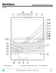
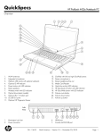
USER MANUAL
COMPUTRAC® VAPOR PRO® 3000
MOISTURE ANALYZER
OPERATION MANUAL
Firmware Rev 1.002
February 1998
ARIZONA INSTRUMENT LLC
3375 N Delaware Street | Chandler, AZ 85225 USA
800.528.7411 | 602.470.1414 | f 602.281.1745
www.azic.com
Email:
General – [email protected]
International – [email protected]
Customer Service – [email protected]
AZI P/N 700-0012-C1
Last update February 1998
Computrac 3000™
PROPRIETARY RIGHTS NOTICE
The material in this manual contains valuable information developed by Arizona
Instrument LLC for use with the Computrac line of moisture analyzers. No part of this
manual can be reproduced or transmitted in any form or by any means, electronic,
mechanical, or otherwise. This includes photocopying and recording or in connection
with any information storage or retrieval system without the express written permission of
Arizona Instrument.
ALL RIGHTS RESERVED
© Copyright 1998 Arizona Instrument LLC
Page 2 of 51
Table of Contents
INTRODUCTION . . . . . . . . . . . . . . . . . . . . . . . . . . . . . . . . . . . . . . . . . . Page 4 of 57
PRINCIPLES of OPERATION . . . . . . . . . . . . . . . . . . . . . . . . . . . . . . . . Page 5 of 57
UNPACKING . . . . . . . . . . . . . . . . . . . . . . . . . . . . . . . . . . . . . . . . . . . . . Page 6 of 57
INSTALLATION . . . . . . . . . . . . . . . . . . . . . . . . . . . . . . . . . . . . . . . . . . Page 7 of 57
Check Sensor Status . . . . . . . . . . . . . . . . . . . . . . . . . . . . . . . . . . Page 9 of 57
Dry System . . . . . . . . . . . . . . . . . . . . . . . . . . . . . . . . . . . . . . . . Page 10 of 57
CALIBRATION TESTS . . . . . . . . . . . . . . . . . . . . . . . . . . . . . . . . . . . . . Page 12 of
Syringe Technique . . . . . . . . . . . . . . . . . . . . . . . . . . . . . . . . . . . Page 12 of
Calibration Check . . . . . . . . . . . . . . . . . . . . . . . . . . . . . . . . . . . Page 14 of
Sensor Calibration . . . . . . . . . . . . . . . . . . . . . . . . . . . . . . . . . . . Page 15 of
57
57
57
57
RUNNING MOISTURE TESTS . . . . . . . . . . . . . . . . . . . . . . . . . . . . . . . Page 17 of
Select Test Settings . . . . . . . . . . . . . . . . . . . . . . . . . . . . . . . . . . Page 17 of
To Enter Material Name . . . . . . . . . . . . . . . . . . . . . . . . . . . . . . Page 17 of
To Set Programmed Test Temperature . . . . . . . . . . . . . . . . . . . . Page 18 of
To Select Units for the Final Result Display . . . . . . . . . . . . . . . . Page 19 of
To Select How to End the Test . . . . . . . . . . . . . . . . . . . . . . . . . . Page 19 of
Run Moisture Test . . . . . . . . . . . . . . . . . . . . . . . . . . . . . . . . . . . Page 23 of
57
57
57
57
57
57
57
COMPUTRAC 3000 MENU SYSTEM . . . . . . . . . . . . . . . . . . . . . . . . . . Page 24 of
MEMORY START MENU . . . . . . . . . . . . . . . . . . . . . . . . . . . . Page 26 of
STORED DATA MENU . . . . . . . . . . . . . . . . . . . . . . . . . . . . . . Page 26 of
CALIBRATION MENU . . . . . . . . . . . . . . . . . . . . . . . . . . . . . . . Page 26 of
SETUP MENU . . . . . . . . . . . . . . . . . . . . . . . . . . . . . . . . . . . . . . Page 28 of
DIAGNOSTIC MENU . . . . . . . . . . . . . . . . . . . . . . . . . . . . . . . . Page 29 of
57
57
57
57
57
57
CONDITION PROMPTS and SYSTEM FAILURE CODES . . . . . . . . . . Page 30 of 57
Condition Prompts . . . . . . . . . . . . . . . . . . . . . . . . . . . . . . . . . . . Page 30 of 57
System Failure Codes . . . . . . . . . . . . . . . . . . . . . . . . . . . . . . . . . Page 32 of 57
COMMONLY ASKED QUESTIONS . . . . . . . . . . . . . . . . . . . . . . . . . . . Page 33 of 57
REPAIR AND MAINTENANCE . . . . . . . . . . . . . . . . . . . . . . . . . . . . . . Page 38 of 57
APPENDIX A - ELECTRONIC BALANCE . . . . . . . . . . . . . . . . . . . . . . Page 47 of
Unpacking and Setup . . . . . . . . . . . . . . . . . . . . . . . . . . . . . . . . . Page 47 of
The On/Off Switch . . . . . . . . . . . . . . . . . . . . . . . . . . . . . . . . . . . Page 49 of
Connecting the External Balance to the Computrac 3000 . . . . . . Page 50 of
The Zero Switch . . . . . . . . . . . . . . . . . . . . . . . . . . . . . . . . . . . . . Page 51 of
Unit of Weight Selection . . . . . . . . . . . . . . . . . . . . . . . . . . . . . . Page 51 of
The Send Switch . . . . . . . . . . . . . . . . . . . . . . . . . . . . . . . . . . . . Page 51 of
The Function Switch . . . . . . . . . . . . . . . . . . . . . . . . . . . . . . . . . Page 51 of
Auto-Calibration (CAL 1) - Using an External Calibration Weight
. . . . . . . . . . . . . . . . . . . . . . . . . . . . . . . . . . . . . . . . . . . Page 52 of
RS-232 Front Panel Configuration . . . . . . . . . . . . . . . . . . . . . . . Page 53 of
57
57
57
57
57
57
57
57
57
57
APPENDIX B - SPECIFICATIONS AND RATINGS . . . . . . . . . . . . . . . Page 55 of 57
Page 3 of 51
INTRODUCTION
Arizona Instrument is proud to continue its leadership developing new technology in the moisture
analysis industry. The COMPUTRAC 3000 has been recognized by R&D Magazine as one of the
100 most technologically significant new products of 1997.
A revolutionary moisture analyzer with a detection limit of 10 ppm, the COMPUTRAC 3000 uses
a sensor-based technology and correlates to the Karl Fischer coulometric titration method (with
an oven attachment) in precision and accuracy. The analyzer does not utilize reagents, minimizes
consumables, and is simple to operate.
1997 Winner!
R&D Magazine
Technology 100
Award
Principles of Operation: The COMPUTRAC 3000 heats a sample of test material in a septum
bottle. Evolved volatiles are passed through a cold trap filter to an analysis cell, where the
moisture content of the flowing gas is measured. A microprocessor integrates the varying
moisture signal and converts the signal to micrograms of water for display. Results are available
in parts per million, percent moisture, or total micrograms of water. Arizona Instrument's
innovative prediction algorithm automatically terminates the test in just minutes when sufficient
information is collected to allow accurate determination of the sample's moisture content. The
heating range of the COMPUTRAC 3000 is 25 OC to 275 OC. Test parameters such as sample
size, heater temperature and test ending criteria can be altered to optimize speed and accuracy.
Performance: Designed for either lab or production floor use, the COMPUTRAC 3000
Moisture Analyzer uses patented, state-of-the-art technology specifically designed to provide
accurate and precise results in a timely manner. This ensures that product quality is achieved and
maintained.
The Computrac 3000 stores programed memory settings for up to seven materials and retains the
data from the last 30 sample test runs. The software automatically calculates the statistics of any
selected stored data upon demand. All retained test data can be automatically sent to an external
printer or personal computer at the end of a test or on request.
A factory-calibrated syringe provided in the accessory kit permits quick and easy system
verification. System calibration is checked in just minutes. Re-calibration is a menu driven twostep procedure to assure accurate and reliable results day after day. Built-in self diagnostics
constantly monitor system conditions to detect and report any abnormalities in the hardware,
software, moisture sensor or flow system.
Page 4 of 51
PRINCIPLES of OPERATION
The COMPUTRAC 3000 utilizes a cylinder shaped bottle heater, a dry-gas flow system and a
moisture sensor. The instrument heats a sample of test material contained in a 20 ml (mililiter)
septum bottle. Volatiles driven from the sample pass through the manifold containing the Relative
Humidity (RH) sensor, where the evolved moisture is measured. A microprocessor uses the
collected data to generate an accurate measurement of the moisture content in the sample. The
instrument then displays the result in terms of:
• Parts per million (ppm) H 2O,
• Micrograms (µg) H2O, or
• Percentage (%) H2O.
Figure 1 CT-3000 Basic Flow System
The main sensor used to detect water in the gas stream is a polymer capacitor relative humidity
sensor. The reading from this sensor is combined with manifold temperature and outlet flow rate
to determine absolute micrograms of water per second.
Test parameters such as temperature, ending criteria, and sample weight entry can be changed to
optimize test speed and accuracy. See Appendix B, beginning on page 55, for detailed
specifications and operating limits.
Page 5 of 51
UNPACKING
Unpack the instrument and locate the following items:
AZI P/N
• COMPUTRAC 3000
• Line cord for 120 VAC
200-0002
Y990-0063
• Accessory Kit
990-0068
<
One 1.0 µl Hamilton Syringe
990-0064
<
Ten 20 ml Sample Bottles with
Septums and Caps
990-0057
<
One Replacement Sample Probe
990-0058
<
Two Injection Port Septums
990-0059
<
One Hydrophobic Filter Disk
700-0012
<
User’s Manual
200-0002
<
Power Cord
Optional Items:
• Balance with interface cable
• Printer
• 101-key keyboard
• Dry Air Generator
Y990-0082
Y990-0098
990-0088
600-0169
If you are unable to locate any of the standard items or have questions regarding the optional
accessories, please contact AZI Customer Service at (800) 528-7411 or (602) 470-1414.
Page 6 of 51
INSTALLATION
2
Place the Computrac 3000 on a solid level surface that is large enough to accommodate the
instrument and any accessories or materials that may be required for your work (balance,
printer, sample bottles, samples, etc.).
Figure 2 Rear Panel of the CT-3000
3
Using 1/4", formulation 2075, Tygon™ tubing, AZI P/N 345-0050, attach a dry nitrogen or
carrier gas source to the Flow Inlet Port fitting on the back of the instrument, indicated by
an arrow pointing to the connector.
4
Adjust the source pressure to between 7 and 12 psi.
5
If you plan to use a printer, electronic balance, and/or computer connect them to the marked
connectors at the back of the instrument. The accessory keyboard plugs into a fitting on the
right side of the instrument.
6
Power control and fuses are located at the rear of unit. Plug the instrument line cord into
the matching port on the back of the instrument and a dedicated, 110 VAC, 60 Hz, 15 Amp
line source. Never use any power cable other than the one provided or of equivalent UL
listed ratings. Be sure that the ground pin of the power source is properly grounded. Never
cover the power receptacle so that the power cord can not be removed quickly and easily.
7
Toggle the power switch at the rear of the unit to the ON (I) position.
Page 7 of 51
8
After a quick view of the instrument identification and the firmware version, the Main Test
Screen will appear.
Figure 3 Main Test Screen
9
Allow the instrument to warm up for 20 minutes.
Page 8 of 51
Check Sensor Status
From the Main Test Screen, select Menu to reveal the Main Menu. Use the buttons below
the display on the front panel to move through the menu screens and system
settings.
1
Move the cursor down to highlight the Diagnostic
Menu.
2
Press [Selct].
Figure 4 Select Diagnostic Menu
3
Verify the View System Sensor Status option is
highlighted.
4
Press [Selct] again to view the Sensor Status
Screen.
Figure 5 Diagnostic Menu
5
6
Adjust the nitrogen source pressure (if necessary
but not to exceed 12 psi) so that the Flow in and
Flow out rates are both at the optimum setting of
100 ml/min (±3 ml/min). NOTE that the flow out
may read slightly higher than the flow in.
• If the suggested rates are not obtained, see
“How do I Calibrate the Flow Sensors?” on
page 41.
Figure 6 View Sensor Status Screen
Return to the Main Test Screen by pressing [Esc] three times.
Page 9 of 51
Dry System
NOTES: For all tests using a bottle, the bottle should not be moved into the heater until a screen
prompt appears directing that the bottle be inserted. If the bottle is moved in too soon,
it may be ejected and the test results affected.
ENSURE the slick side of the septum is to the inside of the bottle or the moisture
trapped in the septum will cause false moisture indications.
1
From the Main Menu, select in order:
• Memory Start Menu
• Add/Edit Memory Start
• *FILTER DRYDOWN*
2
ESCAPE to the Main Test Screen.
3
PREPARE a new, clean and dry, sample bottle to
be positioned into the heater during the next set of
steps.
4
When the display indicates “Ready to Test,” PRESS START.
5
When prompted, insert the clean sample bottle into the heater.
6
When the instrument signals “End of Test:”
• Depress [Menu],
• Select Memory Start Menu
• Select Add/Edit Memory Start
• Select *BOTTLE PURGE*
7
Press [Esc] several times until the Main Test
Screen is displayed.
Figure 7 Select Filter Drydown
Figure 8 Select Bottle Purge
8
When the display indicates “Ready to Test,” PRESS START.
9
When prompted with
10
This test will run for 15 minutes to purge moisture that may have migrated into the system.
• If the result is more than 100µg, repeat the bottle purge test.
• If the result does not fall under 100µg after the 3rd or 4th test:
• Ensure the slick side of the septum is to the inside of the sample bottle.
• Check and/or change the hydrophobic filter, see page 39.
• Call AZI Customer Service at (800) 528-7411 or (602) 470-1414.
Page 10 of 51
, insert the sample bottle into the heater.
CALIBRATION TESTS
The water calibration test verifies that the instrument is working properly. This test only takes a
few minutes. Arizona Instrument recommends that:
• This test be run every day to verify the system’s calibration and accuracy, and
• The syringe be returned for calibration annually or if damage is suspected.
Syringe Technique
The information presented here will help you perform the test described on the next page. The
syringe uses the volume inside the needle as its calibrated quantity. It is important to eject any
trapped air to properly fill that volume. Insert the syringe needle through the septum of a sample
bottle of clean water (distilled or de-ionized water). Depress the plunger all the way down.
Slowly withdraw the plunger to the stop. Rapidly depress the plunger all the way and observe the
needle tip for small bubbles. If any appear, repeat the cycle until none appear. Slowly withdraw
the plunger to the stop and hold it against the stop while withdrawing the needle from the septum.
To prevent loss of water from the syringe by capillary action, do not touch the needle tip to
anything until it is inserted into the calibration port of the instrument. When prompted by the
instrument, place the needle tip in the injection port at the top of the instrument, and insert it
straight down until the septum is contacted. Push it in until it touches the bottom of the injection
port.
Figure 10 Correct Placement
Figure 11 Incorrect Placement
Be careful not to move the plunger while inserting the needle. Depress the plunger all the way
with a firm, smooth stroke. Remove the needle from the injection port immediately.
Page 11 of 51
Calibration Check
1
Ensure that the TEST: prompt on the main screen
reads wCAL TESTw. If not, press [Memry],
move the cursor up to highlight wCAL TESTw
and press [Selct].
2
Remove the one microliter syringe from the box.
• The syringe has been factory set to
approximately 500µg. The actual calibration
Figure 12 “CAL TEST” Displayed
value is written on the side of the syringe.
• Depress the plunger to the stop. Insert the
needle through the septum of a sample bottle containing distilled or de-ionized water.
3
Draw water into the syringe. Quickly cycle the syringe through its full stroke while in the
water, to eliminate any air bubbles in the capillary and shaft.
4
Draw the water up slowly into the syringe.
5
Press the [START] key on the Computrac 3000. It is important to begin the test promptly
since the water will evaporate out of the syringe needle. Almost immediately, the screen
will display the blinking message “HAND INJECT WATER NOW.”
6
Inject the sample by inserting the syringe needle all the way down into the injection port.
The rounded needle tip should touch the bottom. Depress the syringe plunger; wait a
second or two and remove the needle. This method will help to optimize the water
transition and minimize the test time.
7
Allow the test to proceed until completed. It should take less than 3 minutes.
8
If desired, perform another four calibration injections and calculate the statistics for the
water injection results for instant performance analysis.
• To do this, press [Menu] for MAIN MENU,
• Press [Selct] for STORED DATA MENU,
• Press [Selct] for ANALYZE STORED DATA,
• Highlight and [Selct] the desired results to be included in the statistics, and
• Press [STAT] to calculate Average, Standard Deviation, and Coefficient of Variation.
9
The average should fall within ±5% of the calibrated syringe’s value.
10
If the mean result does not fall within the ±5% range, a sensor calibration should be
performed.
Page 12 of 51
Sensor Calibration
NOTES:
• Only a one microliter, (1µl), syringe which has been calibrated to .5µl, with the
exact weight in µgrams clearly visible will be used for this calibration or an NIST
traceable syringe set to .5µl/500µg.
• This syringe has a very small barrel and piston which must be properly cared for
to assure a correct injection is delivered to the instrument. After first use, the
syringe must be stored in a desiccant box or it will become immobilized internally.
• Once the syringe has become immobilized, it should be replaced.
• The syringe should be returned to AZI annually for calibration or if damage is
suspected. Contact AZI Customer Service at (800) 528-7411 or (602) 470-1414 to
obtain a Return Material Authorization (RMA) number and prompt
replacement.
• AZI Part Numbers of most used items:
<
SEPTA, Injection Port
990-0058
<
FILTER, Hydrophobic
990-0059
<
BOTTLE, Sample, (Black top only)
990-0064
<
SYRINGE, 1µliter, calibrated to 0.5µliter
990-0068
<
SEPTA, Sample Bottle
990-0074
1
SELECT IN ORDER:
• Memory Start Menu
• ADD/EDIT Memory Start
• *Cal Test*
2
Press [Esc] several times until the Main Test Screen appears.
3
Prepare the Syringe with distilled or deionized water.
• Insert the syringe into the water bottle and fill the syringe.
• Rapidly depress the syringe’s plunger to expel any air in the barrel.
• Fill the syringe and hold the plunger against the stop.
• Remove the syringe from the bottle.
4
When the “READY TO TEST” is displayed:
• Depress the Start Button.
5
When the “INJECT WATER NOW” prompt flashes on the display:
• IN ONE CONTINUOUS MOTION;
<
Insert the syringe into the instrument to the stop,
<
Rapidly press the plunger down, and
<
Remove the syringe.
NOTE:
EACH TEST WILL TAKE ABOUT TWO (2) MINUTES.
Page 13 of 51
6
When the instrument again indicates “READY TO TEST,” perform steps 3 through 5 at
least four (4) more times, for a total of five (5) valid results within 10µg of each other.
7
When the five tests results are available, press [Esc] several times until the Main Test Screen
appears.
8
Select the Stored Data Menu
9
Select View Stored Data
• Delete those test which are out-of-limit due to poor syringe technique.
• Delete any tests not of this test cycle.
• Press [Esc] to return to the Stored Data Menu
10
Select Analyze Stored Data and review each test.
• Valid tests should be within 10 µgrams of each other.
• Select the five closest results.
NOTE: At least five (5) valid tests are required for the proper analysis and correction
factors to be calculated. If five valid results are not available, repeat the tests
until they are available.
11
Depress [STAT]:
• Review the results of the calculation
• Standard Deviation should be less than 10%
• Coefficient of Variation should be less than 2%
12
Select Calibration Menu.
13
Select Perform Calibration.
14
The result screen will look similar to the
sample at left.
• Press the [Accpt] Key to store these new
results into memory.
Number of Tests
Average
Standard Deviation
Coefficient of Variance
5
519.7 ug
7.8 ug
1.5%
Sample Calibration Display
15
The new calibration numbers will remain in memory until the next sensor calibration is
performed. The injections used for this calibration will be automatically marked so they will
not be used for the next calibration.
16
Press the [Esc] key several times until the Main Test Screen appears.
17
Perform at least one more water injection to verify the accuracy of the calibration.
Page 14 of 51
RUNNING MOISTURE TESTS
The Computrac 3000 has seven available positions to store test parameters for different materials.
Storing the parameters ensures that each test of the same material will use the same parameters to
assure accurate, reliable, and repeatable testing.
Select Test Settings
1
From the Main Menu, select Memory Start
Menu.
Figure 13 Memory Start Menu
2
From the Memory Start Menu select Add/Edit
Memory Start.
3
Move the cursor down to an available memory start
setting (a blank line).
Figure 14 Memory Start Menu
To Enter Material Name
Press [Selct] then [Edit] at the Edit Sample ID line.
and
•
4.1 Use the • and arrow keys to scroll through the alpha-numeric characters. The
arrow keys move the cursor’s position left and right.
•
4
•
¡TIP¢
Use the arrow keys on the 101-key keyboard to navigate the menu system if it is
included with your system.
The keyboard makes entry of long strings of characters such as product names
easy, since all the alphabetic and number keys can be used while editing.
5
Move the cursor all the way to the end of the line, then press the Quit, then the Accpt keys.
Page 15 of 51
To Set Programmed Test
Temperature
6
Determining the Test Temperature.
6.1 Generally, use the highest temperature possible without causing other ‘undesirable’
conditions (such as melting or excessive release of other volatiles). The instrument is
relatively insensitive to the exact temperature used. Too low a temperature will result in
slow tests and possibly low results. It is important that the sample not melt in most cases.
A melted sample may form an impermeable skin and trap moisture, resulting in a low
answer. If the melting temperature is known, use a temperature 10 or 20 degrees lower. If
it is not known, start at a high temperature (230 to 270) and lower it until the sample no
longer melts. The following guidelines will help to determine test temperature.
6.2 If you are testing pelletized resins or a similar material set the test temperature to 230°C or
the same temperature as used in a pyrolysis oven attachment to a Karl Fischer (KF) titrator.
6.3 If you are testing any other type of material set the temperature to 130°C.
6.4 Run a moisture test.
If the sample doesn’t melt, raise the temperature 10°C and return to step 6.4.
•
If the sample melts, lower the temperature 10°C and repeat the test until condition is no
longer observed.
7
Highlight the “Temperatures” on the Edit Memory Start Menu.
8
Press [Selct], then [Edit].
•
9
Use the • and arrow keys to select the desired testing temperatures. The
arrow keys move the cursor’s position.
When complete, move the cursor to the end of the line. Press [Quit], then [Accpt].
Page 16 of 51
and
•
•
•
•
To Select Units for the Final
Result Display
10
Highlight the Result Display Option line.
11
Press [Selct], then [Edit].
11.1 Use the • and arrow keys to select the type of moisture value for the test result to be
displayed. Either:
• Percentage, (%) of water,
• Parts per million (ppm) of water, or
• Micrograms (:g) of water measured.
•
12
Press the Quit, then the Accpt keys.
To Select How to End the Test
13
Highlight the Ending Criteria line.
14
Press [Selct], then [EDIT].
•
14.1 Use the • and
arrow keys to choose the type of ending value.
•
Rate ends the test when the moisture evolved from the sample drops below the
programmed microgram per second value. Use RATE if you want to match an existing
standard or method that utilizes a RATE criteria (such as the KF titration method).
This method is extremely dependent on the amount of sample used and water collected
during a test. For repeatability testing, use a very consistent sample size that is within ±
10 percent.
•
Predict ends the test when the built-in programmed criteria, which mathematically
calculates the end point moisture content, has been satisfied. Use PREDICT if you
want to more accurately determine the actual moisture content or are working
independently of other standards or methods. This potential calculation monitors
moisture loss from the sample to extrapolate the final moisture concentration and
provides the quickest test times.
•
Time ends the test when the programmed testing period has elapsed. The test will end
when a selected amount of time has passed. Any value from 001 to 999 minutes may
be entered. Fixed time ending is seldom superior to the predict calculation but is useful
when conducting application characterization tests, or when investigating long term
stability of the instrument.
Page 17 of 51
15
If you are attempting to match KF analysis results, find out what sample size and
‘sensitivity’ setting was used in the KF procedure. Use approximately ten times as much
sample in the Computrac 3000, and set the rate ending criteria value to ten times the
‘sensitivity’ value used in the KF equipment.
Example:
16
KF Sensitivity Setting
0.1 :g/sec
KF Sample Size
0.5 grams
Computrac 3000 End Rate
1.0 :g/sec
Computrac 3000 Sample Size
5 grams
If you do not have the KF parameters available, perform the following experiment.
16.1 Select a sample size that will yield 500 to 1000 micrograms of water, or use the table below.
Expected Moisture
Use
0 - .005%
0-50 ppm
10-20 grams
.005 - .015%
50-150 ppm
5-10 grams
.015 - .035%
150-350 ppm
2-5 grams
.035 - .075%
350-750 ppm
1-2 grams
.075 - .150%
0.5-1 gram
.150 - .350%
0.2-0.5 gram
.350 - .750%
0.1-0.2 gram
.750 - 1.5%
0.05-0.1 gram
16.2 For best accuracy and speed, the sample should evolve between 500 and 1000 micrograms
of water during the test. Larger amounts will not significantly improve accuracy, and will
only add to the test time. Smaller quantities will result in faster tests but may degrade
accuracy, depending on the properties of the sample. No damage to the instrument will
ensue if samples are too small, but samples that evolve more than about 10,000 micrograms
of water or other volatiles may result in condensation of water or volatiles in the output
flow sensor, damaging it.
16.3 To estimate sample size, you must have some idea of the approximate moisture content of
the sample. Use the calculation shown below to estimate the minimum sample size.
Minimum Sample Grams =
Example:
Page 18 of 51
0.05
Expected Moisture %
Expected Moisture is 0.05%
Minimum Sample = 0.05/.05 = 1.0 grams
(500µ g water)
16.4 Similarly, the maximum sample is determined by what size sample will release 1000
micrograms of water.
Maximum Sample Grams =
Example:
0.1
Expected Moisture %
(1000 µ g water)
Expected Moisture is 0.05%
Maximum Sample = 0.1/.05 = 2.0 grams
16.5 These are only guidelines. Experiment with your sample to refine the size estimates to
achieve your desired speed and accuracy. Note that if you are using a rate ending criterion,
and the peak moisture rate is less than 5 times the rate threshold, the sample sizes should not
be allowed to vary more than about 10%. Larger variation of sample size will lead to a
larger variation of results.
17
If you are not trying to match KF analysis results perform the following experiment.
17.1 Set up the instrument to use time ending, and set the time to 20 minutes.
17.2 Pick an appropriate temperature
(See “Determining the Test
Temperature” on page 18.)
17.3 Run a test and observe the peak rate
on the Rate Graph.
17.4 Use a rate ending value smaller than
1/3 the peak rate, but larger than
0.2 micrograms per second.
17.5 Press [Quit], then [Accpt].
17.6 Press [Esc] several times to return
to the Main Test Menu and verify
Figure 15 Example of Graph
that:
• The name of the test appears next to “TEST:” and
• “READY TO TEST” appears in the status window at the bottom center of the screen.
18
After determining the optimum test parameters, repeat the test once to confirm the results.
18.1 For performance data, run 3 to 5 tests and determine the statistics by:
• Select Stored Data from the Main Menu,
• Select Analyze Stored Data,
• Select the test results you want to analyze, and
• Press [Calc].
Page 19 of 51
Run Moisture Test
19
Tare-weigh a clean, empty sample bottle, including the septum and cap. Based on the
expected moisture content of the sample, determine optimum sample size using the chart on
page 20.
NOTES: Fill the bottle no more than ½ full. ENSURE the slick side of the septum is to the
inside of the bottle.
19.1 Weigh the loaded bottle and record the weight of the sample.
19.2 Press [START].
19.3 When prompted, enter the net sample weight and insert the
bottle. The system will purge the bottle for 28 seconds.
The sensor will again zero and the test begins.
19.4 An audible ‘beep’ will sound when the instrument has
completed the test. Use the table on page 20 and the
FINAL moisture reading on the display to adjust the sample
size accordingly to optimize test time, repeatability and
accuracy.
Page 20 of 51
¡TIP¢
The accessory balance, AZI
P/N Y990-0082, eliminates
possible transcription errors
when entering the sample
weight. It is also faster than
manually taring and
weighing the sample.
COMPUTRAC 3000 MENU SYSTEM
In the idle state, the Main Test Screen displays menu access keys at the bottom. From left
to right they are:
Use either the
and
•
2
[Memry] key - for accessing stored memory start selections,
[Menu] key - for accessing the Main Menu, and
[Graph] key which changes the display to a graph of collected moisture and rate
information.
•
•
•
•
or • and
•
1
arrow keys to make your selection.
Figure 16 Main Test Screen
3
The [Graph] key can be used to switch the display to the graphical displays.
3.1 When [Graph] is pressed, the Total Moisture Graph appears and the name above the arrow
button changes to [Next].
3.2 When [Next] is pressed, the graph changes to display the rate at which moisture is passing
over the sensor.
3.3 Pressing [Next] will now toggle between the two graphs.
4
To return to this Main Test Screen press [Esc].
Page 21 of 51
5
Pressing [Menu] brings up a screen (see Menu Overview Screen below) showing the
following options:
•
•
•
•
•
MEMORY START MENU
STORED DATA MENU
CALIBRATION MENU
SETUP MENU
DIAGNOSTIC MENU
Use the • and arrow keys to scroll through the selections and the
and arrow keys
to “Escape” or “Select” your choice. Note that for some of the later selections, the • and
arrow keys will cycle through available letters and numbers so that names can be spelled
and numeric values may be entered.
•
•
Page 22 of 51
•
6
•
Figure 17 Main Menu Selections
MEMORY START MENU
•
•
•
ADD/EDIT MEMORY STARTS
<
Sets the values for stored test parameters. The parameters are stored by name.
Values are stored for test temperature, ending criteria, method of entry of
sample weight, and bottle purge control.
REORDER MEMORY STARTS
<
Allows the list of stored parameter sets to be rearranged. It also deletes sets
no longer needed, or copies existing sets to another location using the ‘cut and
paste’ method.
PRINT MEMORY STARTS
<
Prints a list of the stored parameter sets on the attached printer, or to an
attached computer. See Printer Setup and Report Setup, Report Content to
arrange the instrument for this purpose.
STORED DATA MENU
•
•
•
•
VIEW STORED DATA
<
Allows viewing and printing of all data stored for a given test.
ANALYZE STORED DATA
<
Permits selection of stored data sets for statistical analysis. Statistical analysis
includes mean, standard deviation (S.D.) and coefficient of variation (C.V.).
REORDER STORED DATA
<
Rearranges the order of the list of stored data sets. It also deletes sets no
longer needed, or copies existing sets to another location using the ‘cut and
paste’ method.
DELETE STORED DATA
<
Facilitates deletion of selected data sets. Selection by line, date or all items.
CALIBRATION MENU
•
•
PERFORM RH SENSOR CALIBRATION
<
To be used carefully and only when required to calibrate the moisture sensor.
When this selection is made the stored data sets and the calibrated syringe
volume are used to calculate and execute the automatic adjustment of the
instrument calibration constant.
EDIT SYSTEM CALIBRATION CONSTANTS
<
This selection allows the entry of the two sensor constants, written on the
sensor card, when a flow manifold is replaced and the adjustment values to
calibrate the flow sensors.
Page 23 of 51
SETUP MENU
•
•
•
•
•
•
CLOCK SETUP
<
Sets the internal clock for the correct time and date.
EXT. BALANCE SETUP
<
Identifies the type of external balance (AZI SP150 or SCI SA80),
<
Selects the tare mode (fixed or manual bottle weight entry or balance entry),
and
<
Verifies the communication link between the instrument and balance
EXT. PRINTER SETUP
<
Identifies the type of data printer used and specifies where the output data is to
be sent (RS-232, LPT or both).
REPORT SETUP
<
Report Control specifies when the report is to be printed (off, at the start, at
the end), selects the output format (text or spreadsheet), specifies the reporting
interval in seconds, turns on or off end-of-line automatic formfeeds, selects
which graph to print (both, rate, result, none), and turns lot number recording
on or off.
<
Report Content specifies whether particular items of information are to be
included in the report, or not. These items are:
Memory Start Number
Memory Start ID Text String
Lot Number
Product ID Text String
Test Date and Time
Final Result (ppm or %)
Final Mass (micrograms H2O)
Ending Criterion
Sample Weight
Test Time
Test Temperature
Ending Rate (micrograms/sec at end of test)
<
Edit Company Name allows you to change the company name that prints on
the header line of the report.
ACCESS KEY SETUP
<
Allows entry of the secret access codes used to prevent unauthorized alteration
of stored parameter sets, or stored data sets. The master key controls all
functions. The Params key controls memory start parameter list access.
SEPTUM RECORD SETUP
<
This function resets the injection port septum counter. When the septum has
been used 60 times, a message will warn the operator to replace it. When the
replacement is accomplished, use this function to reset the count to zero.
Page 24 of 51
DIAGNOSTIC MENU
•
•
NOTE:
•
•
VIEW SYSTEM SENSOR STATUS
<
Displays RH sensor value, flow in and out, manifold temperature (RTD*),
bottle heater temperature, RH sensor temperature, H 2O flow rate and
instrument flow mode.
MANUAL FLOW CONTROL MENU
<
This menu allows manual control of the carrier gas flow mode for test and
analysis of possible system faults. There are five selections.
Sensor Drydown (high flow through the manifold and RH sensor but not
the needle or bottle)
Standby (normal flow, through the manifold and RH sensor)
Bottle Purge (high flow through the needle and bottle, vented)
Sample Test (low flow through all components, bottle must be present)
Off returns the system to automatic control of the flow state.
If any manually controlled flow state is used, ensure the manual flow control is set
to off before attempting normal operation. If this is overlooked, an error message
will be displayed on the main screen.
VIEW SYSTEM EXCEPTIONS
<
A list of the last 20 faults detected by the instrument diagnostic system. Print
the list and fax it to AZI Customer Service at (602) 470-1888 to assist in
diagnosis of possible system failure.
PRINT EXCEPTION REPORT
<
Prints the stored list of instrument diagnostic exceptions.
* RTD stands for Resistive Temperature Detector, and describes the solid state devices used
throughout the instrument to measure temperatures.
Page 25 of 51
CONDITION PROMPTS and SYSTEM FAILURE CODES
To assure proper performance, your Computrac 3000 uses an intelligent self-diagnostic
system to detect any problems in the hardware, software, sensors or flow system. Operating
abnormalities and fault conditions will result in system failure codes or condition prompts.
They will be recorded in the Exception Reports table.
Condition Prompts
Condition prompts indicate operating conditions that prevent starting or completing of a
moisture test. Following each condition prompt are possible causes and recommended
solutions.
1
2
“EXCESSIVE IN/OUT FLOW RATIO”
This prompt indicates that the carrier gas flow out of the instrument is less than 90% of
the flow into the instrument, suggesting a leak.
Possible Cause
Recommended Solution
Faulty bottle septum
Replace bottle septum
Faulty bottle cap
Replace bottle cap
Flow system leak
Locate and eliminate leak
Flow system out of calibration
Calibrate flow system
“INPUT CARRIER GAS FLOW LESS THAN 40 mL/Min”
This prompt results when the source flow into the instrument falls below the specified
rate.
Possible Cause
Recommended Solution
Source of carrier gas not connected
Connect source
Source pressure too low
Increase source pressure to 7-12psi
Flow system plugged
Locate and eliminate blockage
Source connected to ‘flow out’ barb
Connect to ‘flow in’ barb
Flow sensor failure
Call Arizona Instrument
Blocked Needle
Check that bottle septum is not
blocking needle port
Page 26 of 51
3
“THE RH SENSOR WAS NOT READY
This is a normal condition between tests, indicating the drying or ‘zeroing’ of the sensor.
If the condition persists for more than a few minutes then:
Possible Cause
Recommended Solution
Flow system contaminated
Locate and eliminate contamination
System unusually wet
Wait for system to dry
Wet source gas
Install/change external desiccant
chamber
4
“SEPTUM CHECK WARNING”
The septum, at the calibration injection port, has experienced 60 or more water
injections and may be in danger of losing its core into the flow system. Change the
septum and reset the counter by selecting [SETUP MENU] (from the MAIN MENU),
then [SEPTUM RECORD SETUP], then [Go].
5
“BOTTLE RELEASED WHILE TESTING”
This prompt results from premature release or ‘ejection’ of the sample bottle during a
moisture test. Failure of the transport latch is the most likely cause. If this condition
persists, call the Arizona Instrument Customer Service Department at (800) 528-7411
or (602) 470-1414.
6
“BALANCE COMM FAILURE”
This prompt indicates that the memory start used specifies use of a digital balance for
weight entry, but the instrument is not communicating with a balance. Check the cable,
and assure that the balance is powered on, on line, and stable.
Page 27 of 51
System Failure Codes
Occurring less frequently than condition prompts, system failure codes require the instrument
to be switched off and then powered back up. It is possible for a failure to occur due to a
transient condition. However, if the failure persists or occurs frequently, call Arizona
Instrument Customer Service at (800) 528-7411 or (602) 470-1414.
ERRO
R
ERROR MESSAGE TEXT
MOST LIKELY CAUSE
1
TRANSPORT RELEASE ERROR
STUCK BOTTLE RELEASE
2
PC KEYBOARD COM FAIL
BAD CABLE OR CONFIG
3
PC KEY CONTROLLER TIMEOUT
DEAD KEYBOARD
4
FLOW CALIBRATION WARNING
FAILED FLOW SENSOR
5
RH SENSOR RANGE ERROR
FAILED RH SENSOR
6,7
FLOW SYSTEM ERROR
CABLE OR SENSOR FAIL
8
RH RTD RANGE ERROR
CABLE OR RTD FAIL
9
RH RTD RATE ERROR
MANIFOLD HEATER
10
RH RTD TRACK ERROR
MANIFOLD RTD OUT OF POSITION
11
BOTTLE RTD RANGE ERROR
CABLE OR RTD FAIL
12
BOTTLE RTD RATE ERROR
BOTTLE HEATER FAILURE
13
BOTTLE HEATER OVERTEMP
BOTTLE HTR RTD OUT OF POS’N
14
BOTTLE HTR CONTROL ERR
ROOM TOO COLD
15
MANIFOLD RTD RANGE ERROR
CABLE OR RTD FAILURE
16
MANIFOLD RTD RATE ERROR
MANIFOLD HEATER FAILURE
17
MANIFOLD HEATER OVERTEMP
MANIFOLD RTD OUT OF POSITION
18
MANIFOLD HTR CONTROL ERR
MANIFOLD HTR OUT OF POSITION
19
A2D INIT FAILED
COMPONENT FAILURE, MAIN BOARD
20
A2D TIMEOUT ERROR
COMPONENT FAILURE, MAIN BOARD
21
MCU CLOCK FAIL ERROR
COMPONENT FAILURE, MAIN BOARD
22
COP TIMEOUT ERROR
COMPONENT FAILURE, MAIN BOARD
23
ILLEGAL OP CODE TRAP
COMPONENT FAILURE, MAIN BOARD
24
EPROM CHECK SUM FAIL
COMPONENT FAILURE, MAIN BOARD
25
SRAM CHECK FAIL
COMPONENT FAILURE, MAIN BOARD
Page 28 of 51
COMMONLY ASKED QUESTIONS
Below are some commonly asked questions with answers and possible solutions.
Q: “What if my water injection results are zero (or near zero).”
Figure 18 Correct Placement
Figure 19 Incorrect Placement
A: Make sure the syringe is being inserted all the way into the injection port.
Q: “What if my water injection results are out of range?”
A:
Perform a sensor calibration. The Computrac 3000 self-adjusts the internal calibration
factors to the high precision moisture sensor, due to varying conditions (temperature,
product accumulation in the flow system, component wear, etc). Over time, this may
cause the overall calibration to drift slightly. Since sensor calibration is easily
performed, daily verification is recommended.
Page 29 of 51
Q: “How do I dry the instrument after an upset?”
A:
In case the instrument has been flooded with moisture, either by running a very wet
sample, or by exposure to a wet atmosphere, it will be necessary to dry the entire flow
system before normal operation can be resumed.
1
Inspect the filter, tubing, the needle and mount to be sure that no contaminants are
present that might absorb and release large quantities of water. If contamination is
present, replace the contaminated parts with new parts.
2
Confirm that the carrier gas supply is dry. If there is any doubt about this, employ a
drying cylinder in line with the gas supply before connecting it to the instrument gas
input fitting.
3
Begin drydown of the system. Place a clean, dry sample bottle, ensuring that the slick
side of the septum is to the inside of the bottle, in the transport. Go to the memory start
list and select *FILTER DRYDOWN.* Start the test and insert the bottle. Periodically
examine the rate graph display, and see if the moisture rate is falling. If it remains at a
very high level until the end of the test, a source of water is present in the system, and
must be removed before dry-down will succeed. Normally, the rate will begin to decline
after a short time, and eventually will fall to less than 1 :g/sec. When this occurs, a
READY TO TEST message will appear on the display and testing can resume.
Q: “What about interferences?”
A:
The only known interference is methanol. Samples containing methanol should
never be used. Never use methanol as a cleaning agent with the Computrac 3000.
Q: “What is good syringe technique?”
A:
Good syringe technique is essential to accurate calibration. The syringe uses the volume
inside the needle as its calibrated quantity. It is important to eject any trapped air to
properly fill that volume. Insert the syringe needle through the septum of a sample
bottle of clean water (distilled or de-ionized water). Depress the plunger all the way
down. Slowly withdraw the plunger to the stop. Rapidly depress the plunger all the
way and observe the needle tip for small bubbles. If any appear, repeat the cycle until
none appear. Slowly withdraw the plunger to the stop and hold it against the stop while
withdrawing the needle from the septum. To prevent loss of water from the syringe by
capillary action, do not touch the needle tip to anything until it is inserted into the
calibration port of the instrument. Start a *CAL TEST* (see page 14). When prompted
by the instrument, place the needle tip in the injection port at the top of the instrument,
and insert it straight down until the septum is contacted. Push it in until it touches the
bottom of the injection port. Be careful not to move the plunger while inserting the
needle. Depress the plunger all the way with a firm, smooth stroke. Remove the needle
from the injection port immediately.
Page 30 of 51
Store the needle in a dry place. A desiccator box is a good choice. If water is allowed
to remain in the needle, it will cement the needle bore and plunger wire together. If this
happens, do not force the plunger to move, as this will break the wire. Instead, insert
the needle into the water bottle and let it soak for 15 minutes, or until it moves freely.
If the syringe is damaged, or is in need of annual calibration, contact Customer Service
at (800) 528-7411 or (602) 470-1414 for a replacement. After receiving an RMA
number, return the damaged syringe to AZI for repair service.
Q: “Why do my tests sometimes end in less than 2 minutes?”
A:
This is usually caused by an inappropriately large rate ending criterion value. Recall that
when using the rate ending criterion, you entered a rate value to end on. If the sample
moisture is very low, or the sample is too small, the peak rate never exceeds the ending
rate, and the instrument concludes that the test is over. To rectify this, use a larger
sample, or a lower ending rate value. See “To Select How to End the Test” beginning
on page 19.
Q: “How do I transfer stored data to a computer file?”
A:
To store archival information in a computer text file before deleting it from the
instrument memory, set up the instrument to print to the RS-232 port. (Setup Menu,
External Printer Setup). Go to Setup Menu, Report Setup, Report Control and select
text output. Go to the screen showing Print and select the report to be printed. Set up
the computer to receive text information into its serial port at 9600 baud, no parity, 8
data bits and 1 stop bit (9600,N,8,1). Windows Terminal, or Windows 95
Hyperterminal are good choices for this purpose. DOS users should use Procomm or
Terminate, or equivalent utilities. Consult the documentation for your communications
program for details on how to save input data to a file.
Q: “How do I print to a printer?”
A:
To print test results or stored data:
1
Connect the printer to the parallel port on the back of the instrument. Use the
accessory printer from AZI, or a standard PC graphics printer and cable.
2
Make sure the printer is supplied with paper, the printer power is on, and the printer is
on-line.
3
Go to Setup Menu, and External Printer Setup. Select the Printer Type and LPT port.
4
Go to Setup Menu, Report Setup, and Report Control. Select text output.
5
Go to the screen showing Print and select the report to be printed.
Page 31 of 51
REPAIR AND MAINTENANCE
Routine maintenance consists of checking the filter for clogging or contamination, checking
the needles for clogs, and cleaning of the flow path between the needle and the filter. For
clean samples, such as most plastic resin pellets, this is seldom necessary. For very dusty
samples, it may be necessary more often.
CAUTION:
Line voltage is present under the instrument’s cover. To prevent electrical shock, turn
off power and remove the power cord when instructed to do so. Do not re-connect the
power cord and turn power on until after the cover is secured in place.
Figure 20 Cover Release Location
To inspect the filter and tubing, unplug the power cable. Then insert a small probe into the
hole at the back of the instrument. It is marked by a graphic symbol indicating the method of
opening the top cover. Push inward to release the safety catch, and lift the cover up with your
free hand. Remove it and put it in a safe place. The filter is visible at right center, above the
manifold. Be careful not to contact the bottle heater rim as it may be hot enough to
cause a burn. Examine the filter and flex tubing.
If a deposit or discoloration is observed in the flex tubing between the filter and the manifold,
the filter and tubing should be replaced, and the entire sample flow path cleaned with
isopropyl alcohol.
L
***IMPORTANT ***
7
Never use methanol for cleaning any part of the instrument. Methanol interferes with
calibration of the RH sensor, and is very difficult to remove once introduced into the flow
system.
Page 32 of 51
The Hydrophobic Filter on top of the manifold is expected to be replaced when it becomes
contaminated. Replace it only with the Hydrophobic Filter available from Arizona Instrument
(AZI Part No. 990-0059). When replacing a filter, it is good practice to flush the new filter
with dry carrier gas to remove moisture adsorbed to the interior of the filter. After replacing
the filter on its holder, replace the top cover before connecting the instrument to its power
source. Turn the instrument on and when READY TO TEST appears, run the drydown
procedure outlined on page 10 with a clean dry empty sample bottle. When this procedure
ends, the system is ready for reuse.
Q: “How do I change the filter?”
A:
First, obtain a replacement Hydrophobic Filter, AZI Part Number 990-0059. There
should be one in the accessory kit. If none is found, call AZI Customer Service at (800)
528-7411 or (602) 470-1414 for a replacement.
1
Remove the power cord from its socket.
CAUTION:
Line voltage is present under the instrument’s cover. To prevent electrical shock, turn
off power and remove the power cord when instructed to do so. Do not re-connect the
power cord and turn power on until after the cover is secured in place.
2
3
Insert a small probe into the hole at the back of the instrument. It is marked by a
graphic symbol indicating the method of opening the top cover, see Figure 20 on page
38. Push inward to release the safety catch, and lift the top cover up with your free
hand. Remove it and put it in a safe place.
Hydrophobic Filter
Disk, 990-0059
The filter will be found near the right
center on top of the manifold assembly.
CCW to Remove
Pull the flex tubing off the top of the filter
CW to Install
disk. Rotate the filter disk ½ turn
counterclockwise and lift it off. Discard
the old filter and replace it with a new
one. Reattach the flex tubing. If
condensed material is visible in the flex
tubing, replace the flex tubing. Note that
this is a special type of hydrophobic
tubing. The proper tubing is available
from AZI as AZI Part Number 345-0050.
4
Replace the top cover and power cord.
5
Turn the instrument on and perform a *FILTER DRYDOWN* and a *BOTTLE
PURGE,* see page 10.
6
When the drying process concludes, the instrument is ready for normal use.
Figure 21 Filter Disk Location
Page 33 of 51
Q: “How do I change the injection port septum?”
A:
This is a simple procedure. First, obtain a replacement septum. There should be one in
the accessory kit. If none is found, call AZI Customer Service at (800) 528-7411 or
(602) 470-1414 for a replacement.
1
Turn the instrument off and remove the power cord from its socket.
CAUTION:
Line voltage is present under the instrument’s cover. To prevent electrical shock, turn
off power and remove the power cord when instructed to do so. Do not connect the
power cord and turn power on until after the cover is secured in place.
2
Insert a small probe into the hole at the back of the instrument, (see Figure 20 on page
38). It is marked by a graphic symbol indicating the method of opening the top cover.
Push inward to release the safety catch, and lift the cover up with your free hand.
Remove it and put it in a safe place.
3
The injection port needle guide will be
found near the front center on top of the
manifold assembly. Use a 9/16" wrench
to loosen the nut. Turn the nut
counterclockwise to remove it. Lift off
the needle guide and the nut. The septum
is now visible at the top of the injection
port. Replace it with a new one. Replace
the needle guide and nut, hand tightening
it. Using the wrench, turn the nut 1/4 turn
to load the septum. Grasp the needle
guide and make sure everything is
properly aligned and secure.
Needle Guide,
[345-0044]
Retaining Nut,
Supplied with
Needle Guide
Septum,
[990-0058]
Figure 22 Injection Port Septum
Location
4
Replace the top cover and power cord.
5
Turn the instrument on and the instrument is ready for normal use.
Page 34 of 51
Q: “How do I Calibrate the Flow Sensors?”
A:
Follow the steps listed below. A calibrated flow meter that will measure a flow rate of
100 ml/min is required.
1
Verify the pressure of the dry-gas supplied to the instrument is between seven (7) and
twelve (12) psi. (9 to 10 psi is preferred.)
2
Connect the dry-gas supply tube to the Instrument’s Inlet Port.
3
Connect the Instrument’s Outlet Port to a calibrated Flow Meter’s Inlet Port.
4
From the Main Menu, Select in order:
• Calibration Menu
• Edit Cal System Constants
5
Edit the two values, Flow In and Flow Out, to read
100.
6
From the Main Menu, Select in order:
• Diagnostics Menu,
Figure 23 Editing Calibration Value
• Manual Flow Control,
<
BOTTLE PURGE (to allow maximum flow), then
<
STANDBY (to allow flow regulator adjustment).
7
Turn the instrument off and remove the power cord from the source of power.
CAUTION:
Line voltage is present under the instrument’s cover. To prevent electrical shock, turn
off power and remove the power cord when instructed to do so. Do not connect the
power cord and turn power on until after the cover is secured in place.
8
Insert a small screwdriver or other probe into the latch release hole at the back near the
top of the instrument and remove the lid. See Figure 20 on page 38 for release location.
Store the lid in a safe place.
9
Reach through the opening at the top of the instrument and release the two catches at
the top rear, inside the instrument. See Figure 24 for latch locations. This releases the
plastic cover from the metal base. Lift the housing up and towards you, and remove it
from the chassis. Store the cover in a safe place.
Page 35 of 51
Top Cover Latches
Flow Regulator Adjustment
CW to increase flow
CCW to decrease flow
Figure 24 Cover Latches and Flow Regulator Adjustment Locations
10
11
Set the output flow for 100ml/min measured on the flow meter.
• Slowly Adjust the screw on top of the Inlet Flow Regulator CLOCKWISE to
increase and COUNTERCLOCKWISE to decrease the flow until the flow meter
indicates 100 ml/min.
Connect the power cord to the source of power and turn the instrument on.
12
Go to the Diagnostics Menu.
13
Select View System Sensor Status
14
Read and record the exact outlet flow rate as
indicated by the flow meter.
15
Read and record the instrument’s indicated
Flow Out from the display.
16
Divide the Measured Outlet Flow Rate by the
Instruments Indicated Flow Out and multiply
the result by 100 to determine the Flow
Calibration Factor (FCF).
Figure 25 Sensor Status Display
16.1 Example: The flow meter reads 100 while the instrument display
reads 109 for flow out. The result of 91.7 should be rounded up
and a value of 92 used in the next few steps.
Page 36 of 51
100
× 100 = 91.7
109
17
Escape to the Main Menu and select in order:
• Calibration Menu
• Edit System Cal Constant
18
Edit the Flow Out Transducer % Value to the
calculated Flow Out FCF.
19
Escape to the Diagnostics Menu.
20
Select View System Sensor Status.
• Verify that the indicated Flow Out in
ml/min now agrees with the measured flow
rate on the flow meter within ±1 ml/min.
21
If they do not agree, edit the Flow Out
Transducer value to 100% and REPEAT steps
6 through 20.
Figure 26 Editing the Flow Out FCF
Figure 27 Check Indicated Reading
22
WHILE AT THE VIEW SYSTEM SENSOR STATUS MENU, Read and record the
Flow In value.
23
Divide the Indicated Flow Out reading by the Flow In reading and multiply the result be
100 to obtain the Flow In FCF Value.
23.1 Example: The instruments flow out reads 100 while the instrument
flow in 113. The result of 88.4 should be rounded down and a
value of 88 used in the next few steps.
24
Escape to the Main Menu and select in order:
• Calibration Menu
• Edit System Cal Constant
25
Edit the Flow In Transducer % Value to the
calculated Flow In FCF.
26
Escape to the Main Menu.
100
× 100 = 88.4
113
Page 37 of 51
27
Select Diagnostics Menu.
27.1 Select View System Sensor Status.
• Verify that the indicated Flow In value agrees with the Indicated Flow Out value
within ±2 ml/min.
• If it does not, Adjust the Flow In FCF value in the Edit System Cal Constant Menu
so that the Flow In and Flow Out Indications in the System Sensor Status Menu are
equal ±2 ml/min.
28
Press [Esc] to the Diagnostics Menu.
28.1 Select in order:
• Manual Flow Control
• Off
29
Check and if necessary adjust the RH Sensor calibration, see page 14.
Page 38 of 51
Q: “How do I set up the CT-3000 to use the AZI SP150 or SCI
SA800 digital balance?”
A:
Follow the steps below.
1
Beginning at the Starting Screen, select the prompts in order:
• Main
• Setup
• Ext Balance setup
• Select Balance Driver
Figure 29 Setup External Balance
Figure 30 Select Functions
2
Select the AZI SP150 or SCI SA800 according to the balance you have.
• Quit
• Accept
3
Select Tare Mode.
• Fixed Bottle Weight if all sample bottles
weight exactly the same.
• Manual Bottle Weight if all bottles are preweighed by hand.
• Tare Empty Bottle if the balance is to tare
weigh each bottle before it is filled with
sample.
Figure 31 Select Tare Mode
4
Escape (ESC) to the Ext Balance Setup Menu.
5
Connect the cable between the CT-3000 Balance Input and the balance RS-232
Connector.
6
Turn the balance power on and wait for the ready indication.
Page 39 of 51
7
Select Check Balance Comm on the Ext
Balance Setup Menu.
• Select Go and wait for communication to
be established.
• If the check is bad, verify each step above.
Figure 32 Balance Communication
Check
•
8
If the check indicates good
communication, a weight will be shown on
the CT-3000 display.
If the check is good, press [Esc] until the Main
Test Screen is displayed. If not, recheck the
cables and setup conditions.
Figure 33 Oval at bottom will show
weight when communication good
Page 40 of 51
APPENDIX A - ELECTRONIC BALANCE
Unpacking and Setup
The balance, weighing pans, remote power supply and windscreen are packed in a foam
support to protect them from shock during shipping and handling. Save and reuse all packing
material for future damage-free shipments.
Figure 33 Balance Full View
Page 41 of 51
All AZI balances are equipped with a special clamping screw that locks the balance
suspension during shipping. This screw must be loosened before the balance can be
operated (see Figure 34).
•
•
•
Locate the black knob, on the front center of the balance, underneath the display
area.
Remove the paper tag.
Turn the knob, approximately one (1) turn counter clockwise, as shown in Figure
34, until it stops .
If the balance is shipped or moved long distances, the clamping screw should be retightened by turning the knob in the clockwise direction until resistance is felt,
approximately one (1) turn.
Figure 34 Unlocking Clamping Screw
The environment in which your balance is used is very important. Air movement, temperature
changes, vibrations, direct sunlight, etc. influence the performance of high precision balances.
Therefore, place your balance on a solid, sturdy surface that is free of air currents and
vibration. The surface should not be magnetic and should be located away from doors,
windows, heaters, air conditioners and fans.
Level the balance by turning the front feet to center the bubble in the Level Indicator. Turn a
foot clockwise to raise that side or counter-clockwise to lower that side of the balance. Turn
both feet together to raise or lower the front of the balance.
Before making any connections, verify that the power (VAC) requirement shown on the
remote power supply is compatible with the AC power outlet to which the balance will be
connected. First plug the round DIN connector into the rear panel receptacle. Then,
plug the power supply into a grounded AC outlet. Do not alter or bypass the ground
plug in any way. Doing so adversely affects the performance of the balance.
Page 42 of 51
NOTE: Your balance must be plugged in and switched on for at least one (1) hour, then
calibrated, prior to use. Please see the calibration instructions on page 52.
The On/Off Switch
Press the ON/OFF switch and observe the turn on sequence shown below.
Figure 35 Turn On Display Sequence
During this sequence the balance is doing an automatic systems checkout to verify it is
functioning properly.
Page 43 of 51
Connecting the External
Balance to the Computrac
3000
The SP150 balance is configured to interface directly with the Computrac 3000 Moisture
Analyzer. Weight readings at the balance can be transmitted directly to the Computrac 3000
through the null modem cable connection.
To enable this communication between the balance and the Computrac 3000:
1
Power to both units should be switched OFF.
2
Connect the SPECIAL null modem cable (AZI p/n 200-0069) to the RS-232 connector
at the rear of the SP150 balance. Connect the other end of the cable to the balance
connector at the rear of the Computrac 3000.
3
Switch the power to both units ON.
4
On the Computrac 3000, press the Menu key. Use the down arrow key to highlight the
SETUP MENU. Press the Selct key to access this menu. Highlight the EXT
BALANCE SETUP option, and use the EDIT key to select “Computrac” as the external
balance. Press the Accept key to program this option change. Select the Comm Check
option to verify the cable is connected. Use the [Esc] key to return to the MAIN
MENU.
5
At the MAIN MENU, select the Add/Edit Memory Start menu. Access the memory
start to be edited using the up or down arrow keys and the Select key. At the Sample
Weight Entry Mode option, select the option Digital Balance.
When a test is run using that memory start parameter, the Computrac 3000 will automatically
check for data communication. The weight readings from the external balance will be
displayed on the Computrac 3000 display. Follow the display prompts to proceed through the
weighing and testing sequence.
Page 44 of 51
The Zero Switch
Pressing the ZERO switch at any time returns the display to zeros. When a weighing that has
been zeroed out is removed from the pan, a negative reading is displayed. To return to zeros,
press the ZERO switch.
Unit of Weight Selection
Pressing the MODE switch starts the unit of weight cycle as follows: grams (g), carats (ct),
pennyweights (dwt), troy ounces (ozt), and ounces (oz). Press the MODE switch a second
time when the desired unit of measure appears. For Computrac 3000 operation, verify that
the balance is weighing in grams (g).
The Send Switch
Pressing the SEND switch sends the information on the display to the Computrac 3000.
The Function Switch
Pressing the FUNCTION switch cycles the display through four functions as follows:
PCS - front panel parts counting
HI OK LO - check weighing
CAL 1 - auto-calibration
CAL 2 - factory set - do not use
To access the desired function, press the MODE switch when it appears on the display.
CAL 2 is set at the factory and should never require further adjustment. The procedures for
the other three functions are as follows:
Page 45 of 51
Auto-Calibration (CAL 1) - Using an
External Calibration Weight
Perform auto-calibration every time you move your balance. It is extremely important to use
high quality weights and verify the balance has been warmed up for at least one (1) hour prior
to calibration.
Procedure
Display Reading
Remove any containers or
weighings so that only the
stainless steel pan is in place.
Press the ZERO switch.
Zeros are displayed.
Press the FUNCTION
switch.
Display cycles repeatedly through PCS, HI-OK-LO,
CAL1, CAL2.
Press the MODE switch
when CAL 1 appears.
CAL 1 and a flashing O are displayed.
Wait 10 seconds then press
the ZERO switch.
The display stops flashing. In approximately 10 seconds
a weight value or two alternating weight values flash on
the display.
Place the displayed weight
or one of the alternating
weights on the pan.
The display stops flashing and the selected weight is
displayed.
Wait 10 seconds then press
the ZERO switch.
The weight continues to be displayed while the
calibration takes place (approximately 10 seconds). The
display blanks, then displays "OK" and then displays the
calibration weight.
Remove the calibration
weight.
The display returns to zeros and the normal weighing
mode.
Page 46 of 51
RS-232 Front Panel Configuration
The RS-232 Configuration Mode allows changes to the baud rate, front panel control,
software protocol, parity and auto send. The balance is configured at Arizona Instrument to
communicate with a Computrac 3000. AZI preset settings indicated in the following table by
parenthesis around the setting. Any changes to this configuration will affect communication
with the Computrac 3000.
It is not necessary to follow the entire configuration procedure if only one parameter is to be
changed. Follow steps 1 and 2, then use the MODE switch to select the parameter to be
changed, skipping the others. Select the desired setting using the SEND switch, save the
setting using the ZERO switch, then turn the balance off and then on again with the ON/OFF
switch.
To enter RS-232 configuration mode proceed as follows:
Procedure
Display Reading
Turn balance off using the ON/OFF
switch.
Display blanks.
Hold the SEND switch down while
turning balance on using ON/OFF
switch.
OK and the current baud rate, br300, br600,
br1200, br2400, br4800, br9600 or br19,200 is
displayed.
BAUD RATE SELECTION (9600 is
default)
OK SAVEd is displayed followed by OK and the
chosen baud rate.
Press the SEND switch until the
desired baud rate is displayed, then
press the ZERO switch.
LOCAL CONTROL SELECTION,
via front panel, (LC OFF is default.)
Press the MODE switch.
OK and the current front panel control setting,
LC on or LC oFF is displayed.
Press the SEND switch to choose off,
then press the ZERO switch.
OK SAVEd is displayed followed by OK and the
chosen setting.
PROTOCOL SELECTION (Pr OFF
is default.) Press the MODE switch.
OK and the current software protocol setting,
Pr oFF or Pr on is displayed.
Press the SEND switch to choose off,
then press the ZERO switch.
OK SAVEd is displayed followed by OK and the
chosen setting..
PARITY SELECTION (PA nonE is
default.) Press the MODE switch
OK and the current parity setting, PA EVEn,
PAodd or PA nonE is displayed.
Press the SEND switch to choose
nonE, then press the ZERO switch.
OK SAVEd is displayed followed by OK and the
chosen setting.
Page 47 of 51
Procedure
Display Reading
AUTO SEND SELECTION (AS oFF
is default.) Press the MODE switch.
OK and the current auto send setting, AS oFF or
AS on is displayed.
Press the SEND switch to choose off
then press the ZERO switch.
OK SAVEd is displayed followed by OK and the
chosen setting.
CONTINUOUS SEND SELECTION
(CS oFF is default.) Press the MODE
switch.
OK and the current continuous send setting, CS
oFF or CS on is displayed. The display blanks.
Press the SEND switch to choose off,
then press the ZERO switch.
OK SAVEd is displayed followed by OK and the
chosen setting.
DISPLAY BLANKING
SELECTION (bL oFF is default.)
Press the MODE switch.
OK and the current display blanking setting, bL on
or bL oFF is displayed
Press the SEND switch to choose off,
then press the ZERO switch.
OK SAVEd is displayed followed by OK and the
chosen setting.
Press the ON/OFF switch
The display blanks.
Page 48 of 51
APPENDIX B - SPECIFICATIONS AND RATINGS
These specifications are intended as a guide to proper use of the instrument. Specifications
and features will vary with application. AZI product specifications are controlled by ISO9001 procedures and are established and verified during design. They are not to be construed
as test criteria for every application. Refer to AZI document Number 4C04-0001 for current
specifications controlling this instrument. All specifications and features are subject to change
without notice. Periodically contact Customer Service to see if any upgrades are available for
your instrument.
Dimensions:
Approximately 146 mm X 380 mm X 370 mm
Weight:
Approximately 8.6 kg (19 lbs)
Power Ratings:
110 ±10% volts 50/60 Hz, 1 amp standby or 8 amps heat on, or
210 ±10% volts 50/60 Hz, 0.5 amp standby or 4 amps heat on,
Environmental
Requirements:
5 to 40 OC, 0 to 80% RH, non-condensing, indoor use. Optimum
results are obtained from 20 to 40 OC.
Heating Range:
25 OC to 275 OC, electronically controlled
Resolution:
1 microgram, 1 ppm, 0.0001% water in sample
Special Service
Carrier Gas:
Dry nitrogen or dry air (-40 OC dew point, or lower is suggested) at 7 to
12 psig, user supplied.
Rear Panel
Connections:
Parallel printer port (PC standard)
9 pin RS-232 (9600,N,8,1)
9 pin Balance Comm (proprietary protocol and cable)
Power cable receptacle with RFI filter
Carrier gas input barb fitting
Carrier gas exit barb fitting
Side Panel
Connections:
PC keyboard DIN socket
Detection Limit:
10 micrograms (1 standard deviation)
Repeatability:
Depends on sample properties and syringe technique, typically CV is
<10%.
Accuracy:
Depends on sample properties and syringe technique, typically error is
<10%.
Automatic Test
Ending Method:
Rate Threshold, user adjustable
Time, user adjustable
Prediction
Page 49 of 51
Accessory Kit:
Optional
Accessories:
Warranty:
One 1.0 microliter calibrated
syringe
Ten each 20 mililiter sample
bottles with septa and caps
One hydrophobic filter
Two injection port septa
Replacement sample probe
User’s Manual
Power cord for 120 volt use
101 key PC keyboard
PC graphics printer
Digital balance with cable and
Communications Software
Travel case
Dry air generator
990-0064
990-0059
990-0058
990-0057
700-0012
200-0002
990-0088
Y990-0098
Y990-0082
990-0092
600-0169
Instrument is warranted for two years against defects in material or
workmanship. Consumable and routine maintenance are not included in
the warranty. Contact Customer Service for AZI annual maintenance
contract information.
US Patent No. 5,712,421
Foreign Patents Pending
UL and CE Listings Pending
Page 50 of 51
990-0068
TRADEMARK AND COPYRIGHT PROTECTION
Computrac, Arizona Instrument, and the stylized AZI are all registered trademarks of Arizona
Instrument LLC. Instrument firmware is copyright protected.
Copyright 1998, Arizona Instrument LLC. All Rights Reserved.
Arizona Instrument LLC
Computrac 3000 Moisture Analyzer User Manual
Part Number: 700-0012
Revision C1
Document Number 6C21-0017
February, 1998
If you have any questions regarding the operation of this instrument, please call our toll free
number (800) 528-7411 or fax (602) 470-1888. Internationally, call (602) 470-1414 or from
Canada call (800) 528-7411.
Arizona Instrument
3375 N Delaware St
Chandler, AZ 85225 USA
http://www.azic.com
email:
[email protected] - General
[email protected] - International
[email protected] - Customer Support
Page 51 of 51