1
PassPoint Plus
Release 2.00
USER GUIDE
For Access Control Kits
K4878
03/00
IMPORTANT NOTICE
This product complies with Standards of UL294 only. It has not been tested
for compliance with Standards of UL1076. The burglary features of this
product are only supplemental to the product’s access control features.
Terms used in this documentation, such as zones, perimeter, etc., are not
indicative of UL-approved burglary features. These terms apply only to
access control applications of this product and the product’s burglary features
that have not been approved by UL.
ALARM DEVICE MANUFACTURING COMPANY
A Division of Pittway Corporation
165 Eileen Way, Syosset, NY 11791
SOFTWARE LICENSE AGREEMENT
You should carefully read the following terms and conditions. If you do not consent to be bound by this
License Agreement, you must promptly return the unopened package to the person from whom you
purchased it within fifteen (15) days from date of purchase and your money will be refunded to you by
that person. If the person from whom you purchased this Software fails to refund your money, contact
ADEMCO immediately at the address shown above.
Important: This Software is security related. Access should be limited to authorized individuals.
1. GRANT OF LICENSE. Subject to all terms and conditions hereof Alarm Device Manufacturing company, a division of
Pittway Corporation ("ADEMCO") does hereby grant to the purchaser (the "Licensee") upon payment in full of the published
license fee, or other license fee agreed to in writing (the "License Fee") a nontransferable, non exclusive license to use the
enclosed software ("Licensed Programs") provided herewith in Licensee's own business on a single computer for a term
commencing on the date of payment in full of the License Fee and continuing in perpetuity unless terminated in accordance
with the terms hereof.
2. PROPRIETARY RIGHTS. License hereby acknowledges that the Licensed Programs including the algorithms contained
therein are proprietary to ADEMCO. Licensee shall not sell, transfer, disclose, display or otherwise make available any
Licensed Programs or copies or portions thereof to any other entity. Licensee agrees to secure and protect the Licensed
Programs so as to maintain the proprietary rights of ADEMCO therein, including appropriate instructions to and agreements
with its employees.
3. DOCUMENTATION. The documentation supplied with the Licensed Programs is the copyright property of ADEMCO.
Licensee shall not under any circumstances divulge or permit to be divulged such documentation to any other entity.
4. COPIES. Licensee shall not copy in whole or in part the Licensed Programs or documentation provided however that
Licensee shall be permitted to make one (1) copy of the Licensed Programs solely for backup purposes provided that all
proprietary notices are reproduced thereon. Any such copy shall remain part of the Licensed Programs and shall be subject to
this agreement.
5. OBJECT CODE. Licensee understands and acknowledges that the Licensed Programs consist of object code only and that
ADEMCO shall not supply source code versions of the Licensed Programs. Licensee shall not create or attempt to create by decompilation or otherwise, the source code for the Licensed Programs, or any part thereof.
6. SECURITY. Licensee acknowledges that the Licensed Programs are security related and access to the Licensed Software
should be limited to authorized individuals. Licensee assumes full responsibility for use of the Licensed Programs whether by
authorized or unauthorized individuals. Licensee agrees that the License Fee has been set in reliance upon the limitation on
liability contained herein and that such provisions are fair and not unconscionable.
ADEMCO does not represent that the Licensed Programs may not be compromised or circumvented, that the Licensed
Programs will prevent any personal injury or property loss by burglary, robbery, fire or otherwise, or that the Licensed
Programs will in all cases provide adequate warning or protection. Licensee understands that a properly installed and
maintained alarm may only reduce the risk of burglary, robbery or fire without warning, but is not insurance or a guarantee that
such will not occur or that there will be no personal injury or property loss as a result.
DISCLAIMER OF WARRANTIES. ADEMCO does not warrant that the Licensed Programs will meet your requirements, that
operation of the Licensed Programs will be uninterrupted or error-free, or that all Licensed Programs’ errors will be corrected.
The entire risk as to the quality and performance of the Licensed Programs is with you. THE IMPLIED WARRANTIES OF
MERCHANTABILITY, FITNESS FOR A PARTICULAR PURPOSE AND NONINFRINGEMENT ARE DISCLAIMED.
NO ORAL OR WRITTEN INFORMATION OR ADVICE GIVEN BY ADEMCO, ITS EMPLOYEES, DISTRIBUTORS,
DEALERS, OR AGENTS SHALL INCREASE THE SCOPE OF THE ABOVE WARRANTIES OR CREATE ANY NEW
WARRANTIES. SOME JURISDICTIONS DO NOT ALLOW THE EXCLUSION OF IMPLIED WARRANTIES, SO THE
ABOVE EXCLUSION MAY NOT APPLY TO YOU. IN THAT EVENT, ANY IMPLIED WARRANTIES ARE LIMITED
IN DURATION TO NINETY (90) DAYS FROM THE DATE OF DELIVERY OF THE LICENSED PROGRAMS. This
warranty gives you specific legal rights. You may have other rights, which vary from state to state.
8. LIMITATION OF REMEDIES. Licensee's exclusive remedy shall be either the replacement of any diskette or other media
not meeting the limited warranty set forth above and which is returned to ADEMCO with a copy of Licensee's paid invoice or,
if ADEMCO is unable to deliver a replacement that is free of defects, Licensee may terminate this Agreement by returning the
Licensed Programs and thereupon the License Fee shall be refunded. ADEMCO shall have no obligation under this Agreement
if the Licensed Programs are altered or improperly repaired or serviced by anyone other than ADEMCO factory service. For
warranty service, return Licensed Programs transportation prepaid, to ADEMCO Factory Service, 165 Eileen Way, Syosset,
New York 11791.
9. LIMITATION OF LIABILITY. REGARDLESS OF WHETHER ANY REMEDY SET FORTH IN THIS AGREEMENT
FAILS OF ITS ESSENTIAL PURPOSE, IN NO EVENT WILL ADEMCO OR ITS SUPPLIERS BE LIABLE TO YOU FOR
ANY SPECIAL, CONSEQUENTIAL, INDIRECT OR SIMILAR DAMAGES, INCLUDING ANY LOST PROFITS OR
LOST DATA ARISING OUT OF THE USE OR INABILITY TO USE THE LICENSED PROGRAMS OR ANY DATA
SUPPLIED THEREWITH EVEN IF ADEMCO OR ANYONE ELSE HAS BEEN ADVISED OF THE POSSIBILITY OF
SUCH DAMAGES, OR FOR ANY CLAIM BY ANY OTHER PARTY. THIS PROVISION IS INCLUDED FOR THE
BENEFIT OF ADEMCO AND ITS LOCAL REPRESENTATIVES, AND IS ENFORCEABLE BY EACH OF THEM.
SOME JURISDICTIONS DO NOT ALLOW THE LIMITATION OR EXCLUSION OF LIABILITY FOR INCIDENTAL OR
CONSEQUENTIAL DAMAGES, SO THE ABOVE LIMITATION OR EXCLUSION MAY NOT APPLY TO YOU.
IN NO CASE SHALL THE LIABILITY OF THE LICENSED PROGRAMS’ PROVIDERS OR OF ADEMCO EXCEED THE
PURCHASE PRICE PAID FOR THE PRODUCT.
10. REGISTRATION. In order to qualify to receive notification of ADEMCO updates to the Licensed Programs, Licensee
must complete and return a Registration Form to ADEMCO within twenty (20) days from date of purchase. Notwithstanding,
ADEMCO is under no obligation to release updates to the Licensed Programs.
11. TERMINATION. Upon the breach or non-compliance with any term or provision of this agreement, ADEMCO shall have
the right to terminate the license granted hereby by written notice to Licensee. Upon such termination Licensee shall
immediately turn over to ADEMCO all copies of the Licensed Programs and any documentation supplied in connection
therewith. Such remedy shall be in addition to and cumulative to any other remedies ADEMCO may have at law or in equity
with respect to such breach or non-compliance.
12. GENERAL. This agreement is the complete and exclusive statement of the understanding of the parties hereto with respect
to the transaction contemplated hereby and supersedes any and all prior proposals, understandings and agreements. This
Agreement may not be modified or altered except by a written instrument signed by Licensee and an authorized representative
of ADEMCO, its rights, duties or obligations under this Agreement to any person or entity, in whole or in part. If any provision
of this Agreement is invalid under any applicable stature or rule of law it is to that shall be governed by the laws of the State of
New York and the sole venue for suit shall be in an appropriate state or federal court located in the State and City of New York.
The failure of ADEMCO to exercise in any respect any rights provided for herein shall not be deemed a waiver of such right or
any further Agreement may be brought more than two (2) years after the date such cause of action shall have arisen. ADEMCO
shall have the right to collect from Licensee any expensed incurred including attorneys' fees in enforcing its right under this
agreement.
Table of
Contents
Introduction ................................................................................................................... 1–1
About This Guide......................................................................................................... 1–2
What Is PassPoint Plus?............................................................................................... 1–3
Starting PassPoint Plus ................................................................................................ 1–5
The PassPoint Plus Environment ................................................................................. 1–7
User Levels ..................................................................................................................... 2–1
Understanding User Levels.......................................................................................... 2–2
User Level Permissions................................................................................................ 2–4
Assigning User Codes.................................................................................................. 2–7
Managing Cards and the Cardholder Database......................................................... 3–1
About the Cardholder Database ................................................................................... 3–2
Using the Card Wizard................................................................................................. 3–3
Adding a single card ................................................................................................. 3–5
Adding a batch of cards ............................................................................................ 3–8
Adding Cards Manually............................................................................................... 3–9
Using the Action tab ............................................................................................... 3–14
Using the Personal tab ............................................................................................ 3–15
Using the Employment tab ..................................................................................... 3–17
Using the Custom tab ............................................................................................. 3–18
Using the Summary tab .......................................................................................... 3–20
Using the Events tab ............................................................................................... 3–23
Bulk Editing Cards..................................................................................................... 3–24
Bulk editing cardholder access group assignments ................................................ 3–27
v
PassPoint Plus User Guide
Bulk editing cardholder executive privileges/trace ................................................ 3–28
Bulk editing cardholder disabled/expiration data................................................... 3–30
Bulk editing cardholder custom fields.................................................................... 3–32
The Card Monitor ...................................................................................................... 3–34
Creating the Card Monitor Tool ............................................................................. 3–34
Using the Card Monitor.......................................................................................... 3–35
Setting Administration Options ................................................................................... 4–1
PassPoint Administration Options ............................................................................... 4–2
Administration dialog box fields .............................................................................. 4–3
Access Groups................................................................................................................ 5–1
What Are Access Groups? ........................................................................................... 5–2
Creating access groups and setting attributes ........................................................... 5–3
Assigning schedules to an access group ................................................................... 5–6
Assigning access points to an access group.............................................................. 5–7
Disabling and Enabling Access Groups....................................................................... 5–9
Entry/Exit Control...................................................................................................... 5–10
Configuring entry/exit Control ............................................................................... 5–12
Time Scheduling ............................................................................................................ 6–1
What Is PassPoint Scheduling?.................................................................................... 6–2
Set the MLB Time ....................................................................................................... 6–4
Day Templates ............................................................................................................. 6–4
Creating day templates ............................................................................................. 6–7
Holidays ....................................................................................................................... 6–9
Assigning holidays ................................................................................................. 6–10
Time Schedules.......................................................................................................... 6–12
Creating schedules.................................................................................................. 6–14
Resynchronizing Schedules ....................................................................................... 6–20
Event-Action Relationships .......................................................................................... 7–1
What Are Event-Action Relationships?....................................................................... 7–2
Creating event-action relationships .......................................................................... 7–3
vi
PassPoint Plus User Guide
Precedence Levels.......................................................................................................... 8–1
What is Precedence? .................................................................................................... 8–2
Using precedence...................................................................................................... 8–4
Precedence level scenarios ....................................................................................... 8–6
The Event Log ............................................................................................................... 9–1
What Is the Event Log?................................................................................................ 9–2
The Event Browser ...................................................................................................... 9–3
Changing the date range ........................................................................................... 9–4
Archiving Events ......................................................................................................... 9–5
Viewing an archive................................................................................................... 9–7
Performing Access Point Functions........................................................................... 10–1
What Are Access Point Functions?............................................................................ 10–2
Displaying and controlling access points ............................................................... 10–2
Locking access points............................................................................................. 10–5
Protecting access points.......................................................................................... 10–6
Bypassing access points.......................................................................................... 10–7
Granting access to access points............................................................................. 10–9
Shunting and unshunting access points ................................................................ 10–11
Choosing an identification method....................................................................... 10–12
Setting access points as exit-only ......................................................................... 10–13
Configuring visual verification............................................................................. 10–14
Clearing the precedence level of an access point ................................................. 10–15
Anti-Passback .......................................................................................................... 10–16
Configuring Anti-Passback................................................................................... 10–18
Forgiving Anti-Passback ...................................................................................... 10–18
Threat Levels ........................................................................................................... 10–20
Locating or Moving a Cardholder............................................................................ 10–21
Controlling Burglary Zones ..................................................................................... 10–24
The Logical View......................................................................................................... 11–1
The Logical View ...................................................................................................... 11–2
The Logical Tree area............................................................................................. 11–2
The map area .......................................................................................................... 11–4
vii
PassPoint Plus User Guide
The Floor Plan Editor................................................................................................. 11–4
Using the Floor Plan Editor ....................................................................................... 11–5
Creating a Logical View ............................................................................................ 11–8
Step 1: Name the area............................................................................................. 11–9
Step 2: Associate your resources with the area .................................................... 11–12
Step 3: Draw and save your area maps................................................................. 11–13
Using the Logical View ........................................................................................... 11–20
Uploading and Downloading the Database............................................................... 12–1
What Is the Database?................................................................................................ 12–2
System accounts ..................................................................................................... 12–2
What information is in the account database? ........................................................ 12–3
Downloading the database...................................................................................... 12–3
Uploading the database........................................................................................... 12–5
Obtaining Resource Status ......................................................................................... 13–1
What Is Resource Status?........................................................................................... 13–2
Selecting Resource Status .......................................................................................... 13–2
Altering and refreshing the display ........................................................................ 13–3
Access points .......................................................................................................... 13–5
Readers ................................................................................................................... 13–8
Relays ................................................................................................................... 13–10
Triggers................................................................................................................. 13–13
Zones .................................................................................................................... 13–15
Access groups ....................................................................................................... 13–18
Schedules .............................................................................................................. 13–20
Modules ................................................................................................................ 13–21
Partitions............................................................................................................... 13–22
Using PassPoint Reports............................................................................................. 14–1
PassPoint Reporting................................................................................................... 14–2
Using the PassPoint Reporter ................................................................................. 14–4
Viewing reports ...................................................................................................... 14–6
Creating a new report ............................................................................................. 14–8
Running Scheduled Reports..................................................................................... 14–16
viii
PassPoint Plus User Guide
Starting the Report Scheduler............................................................................... 14–17
Configuring the PDF ............................................................................................ 14–18
Configuring web server support ........................................................................... 14–19
Scheduling a report............................................................................................... 14–21
Viewing a saved scheduled report ........................................................................ 14–22
Using the Badger ......................................................................................................... 15–1
Loading the Badger.................................................................................................... 15–2
Creating a Master Badge Format ............................................................................... 15–4
Step 1: Selecting a card size ................................................................................... 15–4
Step 2: Selecting a card background....................................................................... 15–5
Step 3: Inserting card components.......................................................................... 15–6
Step 4: Save your master badge............................................................................ 15–13
Creating and Printing Badges .................................................................................. 15–13
System Defaults ............................................................................................................ A–1
Default System Values................................................................................................ A–2
Keypad Messages...........................................................................................................B–1
Keypad Messages.........................................................................................................B–2
Event Log Messages ..................................................................................................... C–1
Event Log Messages ....................................................................................................C–2
Access Control Glossary .............................................................................................. G–1
Access Control Index .....................................................................................................I–1
ix
PassPoint Plus User Guide
x
Chapter
1
Introduction
Introduction
This chapter describes the content of this guide and explains the
basic use of the PassPoint Plus program. In this chapter you will
learn:
•
What this guide is about and what its contents are
•
What the PassPoint Plus Windows software is and how to
use it.
Introduction
1–1
About This Guide
This guide is for users of the PassPoint access control system. It
contains everything needed to operate the system on a day-to-day
basis once the system has been installed and properly configured.
Who is a user?
A user of the system is a person who interacts with the system
through its interface. Users can control readers, set time
schedules, enroll ID cards, etc.
Users interact with the system on a completely different level from
cardholders. Cardholders are the people who occupy the premises.
They have nothing to do with the configuring or operation of the
system. A user will most likely be a cardholder, but a cardholder
does not have to be a system user.
For example, the PassPoint premises security manager is both a
cardholder and a PassPoint user. He is a cardholder because he has
an access badge to allow him access to the premises. He is also a
system user because he is responsible for configuring and
operating the PassPoint system. He sets up time schedules, enrolls
new ID cards, etc.
There are four different levels of PassPoint users. They are:
Installer, Masters, Managers, and Operators. Each of these user
levels are explained in detail in the following chapter of this guide.
What’s in this
guide?
All of the tasks that a system user performs are described in this
guide.
When using the system, you will be working with the PassPoint
Plus system interface. This system interface allows you to perform
all of the tasks needed to configure, monitor, and operate your
PassPoint system.
1–2
Introduction
PassPoint Plus User Guide
!
▲
PassPoint Plus can operate in different languages. Please note that
all displays and examples in this manual are presented with
English as the defined default language.
What Is PassPoint Plus?
PassPoint Plus is a Windows software program that installs and
runs on your system computer. Essentially, PassPoint Plus allows
your computer to communicate with the main logic board of the
system.
With PassPoint Plus, you can configure all of the options
necessary to get your system up and running, perform system
maintenance, and monitor system functions. While monitoring the
system, PassPoint Plus displays a scrolling list of system events.
A user can then log on and enter the program’s visually oriented
system, which allows full screen editing of configurable options.
!
▲
The PassPoint system does not need to be connected to the
PassPoint Plus computer in order to function. The computer is
used only to configure and monitor the system. Once the system is
up and running, the computer can be disconnected (either
intentionally or unintentionally) without disrupting the operation
of the system.
System requirements
In order to install and run PassPoint Plus, your computer will need
to have the following minimum configuration:
Introduction
1–3
Minimum
•
Pentium-II® 200 MHz
•
32 megabytes RAM
•
80MB free hard disk space
•
Windows 95, Windows 98, or Windows NT 4.0 (service
Pack 3)
•
SVGA video display, 800 x 600 resolution, 256 color
•
Mouse
•
Configured printer for reporting
Recommended
•
Pentium-III® 400 MHz or better
•
64 megabytes RAM or better
•
80MB free hard disk space or better
•
Windows 95, Windows 98, or Windows NT 4.0 (service
Pack 3)
•
SVGA video display, 800 x 600 resolution, 256 color
•
Mouse
•
Configured printer for reporting
Optional
1–4
Introduction
•
Sound Card, Modem, and Internet connection (for custom
event handling)
•
Integral Flashpoint Lite (or better) Video card for onscreen video support
PassPoint Plus User Guide
•
Twain-compliant image-input device, such as a digital
camera and/or scanner, for cardholder imaging if desired
•
Badge Printer for printing custom badges using the
PassPoint Badger
•
2 Hayes-compatible 28.8 modems (or better) used for
PassPoint administration
Display Setting Recommendations
It is preferred that PassPoint Plus be used with an 800 X 600display resolution with at least 16-bit color depth and a normal or
small font setting.
Other System Issues
The PassPoint Plus software will function properly with respect to
basic features using the minimum required system. However, if
you intend to use many of the optional features, such as custom
event processing, or you intend to have a sizable configuration of
hardware and/or cardholders, you will want to use at least the
recommended system.
Starting PassPoint Plus
To start PassPoint Plus on your computer:
1. Select PassPoint Plus from the Windows Program menu.
In a few moments, the system will prompt you for a user name
and password:
Introduction
1–5
2. Enter your user name and password and click OK.
!
▲
Both the default User name and Password are installer. Default
logins exist for Installer, Master, Manager, and Operator; however,
you need to log in as Installer in order to be able to do the
complete installation. Once the system is operational, you should
change the default logins for the system.
Once you click OK, the Connect MLB Server window appears
on your screen.
3. Click on Connect to perform operations on-line with the
MLB, or click on Close to perform operations off-line.
Once you make a selection, the main Plus window appears on
your screen.
!
▲
1–6
Introduction
Always close PassPoint Plus before shutting down your Windows
computer. Improper shutdown of your computer can cause the
computer to experience shutdown problems, as well as possibly
corrupting the PassPoint Plus database.
PassPoint Plus User Guide
The PassPoint Plus Environment
PassPoint Plus has been designed to be simple to use. If you are
already familiar with operating in a Windows environment, you
should have no trouble finding your way around the PassPoint Plus
screen.
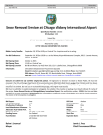
Major screen components
The following illustration shows the main PassPoint Plus screen as
it might look if the system were fully up and running. It includes
cardholders, time schedules, etc.
Menu Bar
Speed Buttons
Resource Control
Tool Bar
Quick
Finder
Logical
View
Window
Resource
Window
Priority
Bar
Event
Window
Status Area
Introduction
1–7
!
▲
The display shown above contains the default layout that is
programmed into the PassPoint software. The content of the
display and its arrangement may be changed by the installer or
user.
Menu Bar - The menu bar allows you to select commands for the
operation of the program.
Quick Finder - The Quick Finder lists all of your system’s
components and resources. Use the list to quickly locate the
system objects you are looking for.
Resource Window - All of your system resources are listed in the
Resource Window. Resources can be modules (like MLBs or
DCMs), relays, zones, triggers, etc. Certain objects in the
Resource Window can be controlled by right-clicking on them or
on a Resource List that contains them.
Priority Bar - The priority bar allows you to select what is
displayed in the Event Window. You may display a chronological
listing of all events as they occur or a chronological listing of
events for any one of the 5 priority levels.
Event Window - Each time a new system event occurs, it appears
in the Event Window. Examples of system events are bypassing a
zone, enabling a relay, disabling a card reader, etc. The most
recent event appears at the top of the list in the Event Window.
Status Area - The Status Area provides information about the
current operating conditions of your PassPoint system. Whenever
an important system event or trouble occurs, a message indicating
the event appears here in red.
Logical View Window – In the Logical View Window, floor
plan(s) or 3-dimensional view(s) can be created showing the
1–8
Introduction
PassPoint Plus User Guide
location of all of your system resources. Resources can be modules
(like MLBs or DCMs), relays, zones, triggers, etc. Certain objects
in the Logical View Window can be controlled by right-clicking on
them.
Resource Control Tool Bar - The resource control tool bar
contains buttons when you select certain items or certain resource
lists. These buttons allow easy control of the selected item. For
example, during operation, if you select an access point in the
resource window, 5 buttons (Bypass, Protect, Lock, Grant, and
Advanced) are displayed.
Speed Buttons - Like the menu bar, the speed button bar allows
you to select commands for program operation. Each speed-button
function has a corresponding menu command on the menu bar. If
you are unsure of the function of a button, place the cursor over the
button; a help bubble is displayed.
NOTE: If you have live video on your system, a Live Video
button will be shown with the other Speed Buttons on the main
screen. When live video is enabled, the Live Video screen shown
below will be displayed in the lower-right corner of the screen. It
is important to note that if you close the live video screen by
clicking on the “X” button in the live video screen, the screen will
close but, your live video button will still be indicating that live
video is enabled. This will not cause any harm but, the next time
you chose to enable the live video, you will need to click on the
button twice (off and on).
Introduction
1–9
1–10
Introduction
Chapter
2
User Levels
This chapter explains how to use PassPoint user access codes. In
this chapter you will learn:
•
What the four PassPoint user levels are and how they are
used
•
About the different level of system access provided by each
user level
•
How to assign user codes
User Levels
2–1
Understanding User Levels
A User of the system is a person who interacts with the system
through one of its interfaces. Users interact with the system on a
completely different level from occupants. Remember that
occupants are cardholders. These are the people who occupy the
premises. They have nothing to do with configuring the system’s
day-to-day operation. This is the job of users.
There are four categories, or levels, of users. Each level has a
different degree of access to the system. The four user levels are:
•
Installer
•
Masters
•
Managers
•
Operators
Installer
The system supports one Installer-level user.
The installer is the only user who is allowed to alter the hardware
configuration of the system. That is, he/she is the only person who
can determine which doors, zones, readers, relays and such are
used by the system.
The installer can also arm and disarm the burglary features of
PassPoint, as well as control all access points (i.e., bypassing and
locking) and general resources (i.e., output relays and triggers). If
the installer arms the system, any other user can disarm it. The
installer cannot disarm the system once it has been armed by
another user.
2–2
User Levels
PassPoint Plus User Guide
Lastly, the installer can modify the occupant card database and
view the event log.
Masters
The system supports four Master-level users.
While the installer is the highest-authority user of the system, a
master is intended to be the highest-authority user of the system
who remains on premises.
A system master can perform all access control and burglary
protection features as well as control uncommitted resources (i.e.,
system resources not associated with access points). The system
master can also perform occupant card database management
functions.
Because the system master is the highest-capability user on the
premises, the master is most likely be the “chief of security.”
Managers
The system supports eight Manager-level users.
A system manager can not perform access control or burglaryrelated control functions. A system manager can perform occupant
card database management functions and perform event log and
data extraction functions.
Managers will most likely be comprised of Human Resources or
Accounting personnel. A manager’s interaction with the system
primarily consists of card database maintenance or accounting data
extraction.
User Levels
2–3
Operators
The system supports eight Operator-level users.
The operator user level is intended to be assigned to guards. When
a user computer terminal is installed at an entry point manned by a
guard, the guard can interact with PassPoint in order to visually
verify an occupant’s identity before allowing entry. If the entry
point is programmed for visual verification, upon the occupant’s
swipe, the guard is prompted with the occupant’s name. The guard
must then indicate if the occupant’s identity is correct before
PassPoint will allow the door to open.
An operator can perform access control and burglary-related
functions. An operator cannot alter the occupant card database.
Every user has
an access code
Each user of the system, whether an installer, master, manager or
operator, is given an access code. This is the code the user uses to
log-in to the system. You have already seen how to log-in using
your default installer code.
In this chapter you will see how to change your default installer
code, as well as how to assign codes to the other users of your
system.
User Level Permissions
In order to help you understand the four user levels, the following
table lists each of the tasks available to each user level from the
menus of the Plus system interface.
2–4
User Levels
PassPoint Plus User Guide
Function
File
Save As (current
configuration as a template)
Select Account
Close Account
Delete Account
New Account
Account Information
Monitor Accounts
Preferences
Exit
View
Collapse Tree
Compress Tree
Real Time Events
Clear Events
Tool Bars
Resource Status
Event Browser
Control
Shutdown MLB
Set Defaults
Set MLB Time
Re-Sync Schedules
Locate Cardholder
Forgive Entry/Exit
Forgive APB
Installer
Master
Manager
Operator
❍
❍
❍
❍
❍
❍
❍
❍
❍
❍
❍
❍
❍
❍
❍
❍
❍
❍
❍
❍
❍
❍
❍
❍
❍
❍
❍
❍
❍
❍
❍
❍
❍
❍
❍
❍
❍
❍
❍
❍
❍
❍
❍
❍
❍
❍
❍
❍
❍
❍
❍
❍
❍
❍
❍
❍
❍
❍
❍
❍
❍
❍
❍
❍
❍
❍
❍
❍
❍
❍
❍
❍
❍
❍
❍
❍
User Levels
2–5
Function
Threat Level
Burg
Config
Hardware
Module
Add
Delete
Properties
Enroll
Configure
Partitions
Resource Lists
System Wide Options
Download
Upload
Admin
System Wide Options
Installer
Master
❍
❍
❍
❍
Manager
Operator
❍
❍
❍
❍
❍
❍
❍
❍
❍
❍
❍
❍
❍
❍
❍
❍
Priorities and
Event Handling
Properties Only
Day Templates
Holiday
Schedules
Access Groups
Event/Actions
Daylight Savings
Cards
2–6
User Levels
❍
❍
❍
❍
❍
❍
❍
❍
❍
❍
❍
❍
❍
❍
❍
❍
PassPoint Plus User Guide
Function
Com
Connect
Setup
Tools
Manage Users
Change Password
Reporting
Event Monitor
Configure Tool
Help
Installer
Master
Manager
Operator
❍
❍
❍
❍
❍
❍
❍
❍
❍
Yourself,
Manager,
and Operator
Only
Yourself and
Operator Only
Yourself
Only
❍
❍
❍
❍
❍
Only your own
Only your own
Only your own
❍
❍
❍
❍
❍
❍
❍
❍
❍
❍
❍
Assigning User Codes
All PassPoint user codes are assigned the same way, using a
dedicated dialog box that lists all the current user codes for the
system.
To reach the User Configuration Tool dialog box, select Manage
Users from the Tools menu. A Login screen is presented
requesting your password. Enter your password and then the
following screen will be displayed:
User Levels
2–7
This dialog box allows the names of the users to be configured and
displays each user’s privileges. Note that because there are
varying levels of log-in authority, any user using this dialog box
can change only their own properties or properties of users at a
lower privilege level.
This dialog box has two panes. The left pane lists the log-in users
and the right pane displays the details about a selected user.
The dialog box also displays a status bar along the bottom. The
two right-most panes of the status bar display the current user and
whether any edits have taken place. If no edits have been
performed on the selected user, the right-most status pane displays
“Browsing.” Once an edit has been performed that has not been
saved, this pane displays “Editing.” In order to save any edits,
use the User...Save Changes menu command or click on a
different user in the User list.
Users List
2–8
User Levels
Click a user in this list in order to update the detail display on the
right side of this screen.
PassPoint Plus User Guide
Fields
First Name - You can edit the first name of each user in this text
box.
Last Name - You can edit the last name of each user in this text
box.
User Disabled - Click this box if you want to temporarily disable a
user’s access.
Prec. Level - Select this drop-down list so that you can choose the
precedence level of each user. Remember that precedence levels
define which users have authority over other users, schedules,
cardholders, and actions.
User Template - This field indicates the type of user that is being
edited.
Template Rights
This list displays the capabilities of the selected user. These
capabilities are defined by the User Template and cannot be
changed.
Menu commands
File Menu
Select Exit from the File Menu when you have finished editing
user data.
User Menu
Reset Password – Use the Reset Password menu command when
you want to set a user’s password back to its default. Doing this
will set the password back to INSTALLER, MASTERx,
MANAGERx, or OPERATORx (with x being the number of the
log-in).
Save Changes – Use the Save Changes menu command when you
want to save your edits without exiting the User Configuration
Tool.
User Levels
2–9
Help Menu
2–10
User Levels
Opens up the Help system.
Chapter
3
Managing Cards and the
Cardholder Database
In this chapter you will learn how to:
•
Use the cardholder database
•
Use the Card Wizard to add a single card or a batch of
cards
•
Add a card to the database manually
•
Bulk edit cards
•
Use the Card Monitor
Managing Cards and the Cardholder Database
3–1
About the Cardholder Database
In order to keep track of all of its cardholders, PassPoint uses a
database. The PassPoint cardholder database contains the names
of all of the cardholders of the premises. It associates each
cardholder with his/her ID card’s code, as well as the cardholder’s
Personal Identification Number (PIN). It is here, in the cardholder
database, that you assign cards and PINs to cardholders.
Adding
cardholders to
the system
Each time you want to issue a card, you are adding a cardholder to
the database. In addition to the cardholder’s name, ID card, and
PIN, you can enter such information as the cardholder’s access
group assignments, the type of card he/she is using, etc. Some of
this information is mandatory to enter. Other information is
optional and is intended to make locating and managing
cardholders easier.
For example, cardholders can be assigned to up to five different
access groups, but they must be assigned to at least one.
Otherwise, they will never be able to access any of your premises’
access points.
Also, each cardholder card can be assigned to invoke a specific
system action. The action can be set to initiate under a variety of
circumstances, such as an access grant, an access denial, or an
egress grant.
Cards can be assigned to cardholders on a temporary basis,
allowing an expiration date or usage count to determine the period
throughout which the card will be valid.
For example, if you want to give a card to a visitor for only one
day, you can set the card to expire on the following day. Or, if you
want the card to work for only three entries into your building, you
can set the card to deny every entry request after the third.
3–2
Managing Cards and the Cardholder Database
PassPoint Plus User Guide
Where do you
start?
There are two main ways to enroll a card. One is to use the Card
Wizard. The other is to use the Add New Card function. Both
methods are explained below:
•
The Add New Card function
This function is chosen from the Config menu or Add New
Card speed button, and brings up a dialog box that allows you
to fill in the data for the card manually.
Adding a card with the Add New Card function allows you the
greatest flexibility. The Card dialog box contains a number of
fields that can be edited and tailored for the particular
cardholder.
The Add New Card function allows you to add only one card at
a time. If you want to add more than one card at a time, use the
Card Wizard.
•
The Card Wizard
The Card Wizard is a PassPoint tool that lets you enroll cards
quickly and easily. Using the Card Wizard, you can enroll a
single card, or you can enroll a batch of cards.
Adding a card using the Card Wizard allows you to add only
basic, default information to the card. It does not allow you the
flexibility that adding a card manually does. However, once
you have added a card using the Card Wizard, you can go back
and add more specific information to that card.
Using the Card Wizard
The quickest and easiest way to add cards is to use the Card
Wizard. With the Card Wizard, you can add one card or a batch of
cards.
Managing Cards and the Cardholder Database
3–3
The Card Wizard appears automatically as the last step of the
configuration process:
To use the Card Wizard, simply follow the instructions and answer
the prompts.
The first step is to determine whether you want to add one card or
a batch of cards. Make your selection by choosing the appropriate
option:
3–4
Managing Cards and the Cardholder Database
PassPoint Plus User Guide
Adding a single card
To enter a single card using the Card Wizard:
1. Select Add a single card in the Wizard and click Next.
The Wizard asks you to enter a last and first name for the
cardholder (i.e., the person to whom the card will be assigned):
2. Enter the appropriate name information into the fields and
click Next.
The system prompts you to enter card information:
Managing Cards and the Cardholder Database
3–5
If you have a Card Enrollment Kit, you can swipe the card at
your enrollment reader to enter the card information.
Otherwise, key the applicable card information into the screen
manually.
▲
!
The default card setting is 34-bit ADEMCO proximity.
3. Enter the card information and click Next.
The Wizard asks you to enter a PIN number for the card. This
is an optional step and needs to be done only if your system
uses keypad readers that enable a PIN to be used:
4. Enter a PIN number (if applicable) and click Next.
Next, the Wizard will ask you to choose access groups for the
card:
3–6
Managing Cards and the Cardholder Database
PassPoint Plus User Guide
Each cardholder can be assigned to up to five access groups.
To assign a cardholder to an access group(s), simply check the
box next to the desired access group(s).
!
▲
The ASK template includes one pre-set access group, called
EMPLOYEES. This enables you to choose an access group
without first having to create one. Later, you can modify or delete
the EMPLOYEES access group if you want.
In order for a cardholder to have any access privileges at all,
he/she must be assigned to at least one Access Group (unless
the cardholder has been granted executive privileges).
5. Select the access groups for the card, then click Next.
The last step is to enter a VISTA user number (if applicable):
Managing Cards and the Cardholder Database
3–7
If the cardholder has a corresponding VISTA user number,
enter it in the field provided. If not, leave this field blank.
6. Click Finish.
The card will be added to the cardholder database. From here
you can view, edit, or delete the card.
Adding a batch of cards
There are two ways to add a batch of cards: batch add and batch
swipe.
Batch Add
Batch adding allows you to quickly add a batch of cards at one
time. The Card Wizard will ask you to swipe (or manually enter)
the FIRST and LAST cards in a batch. The cards must be in
numerical order for this method to work. Once this is done,
PassPoint automatically enrolls both the first and last card, and
every card in between.
3–8
Managing Cards and the Cardholder Database
PassPoint Plus User Guide
Using this method does not allow you to enter cardholder names
for the cards. This must be done separately for each card, along
with any other specific card information you want to add.
Batch Swipe
The batch swipe method also allows you to add a batch of cards,
but this method requires you to swipe each card one by one at a
card enrollment reader.
PassPoint prompts you to choose which access group the
cardholder will belong to, and whether you want to assign a name
to each card. Then, you are prompted to swipe your cards.
Adding Cards Manually
If you don’t want to use the Card Wizard to add a cardholder to the
database, you can simply add the card manually. Adding a card
manually allows you greater flexibility, because there are many
more information fields available to you that allow you to
customize the card.
To manually add a card, follow the procedure below:
1. From the Config menu, select Cards>Add New Card or click
on the Add New Card speed button.
The Confirm dialog box appears:
2. To add cards manually, click on NO.
Managing Cards and the Cardholder Database
3–9
The Card Data dialog box appears:
Each tab allows you to add, edit, or
view different data for the card.
Use the Card
Data dialog box
to add new
cards, edit card
data, delete
cards, and view
events by card.
The Card Data dialog box allows you to enter various types of
information about each card. Each tab of the box displays a
different set of data. When creating a new card record, you fill
out these fields as applicable. Some of these fields, like a
unique Card Code and/or PIN Code are mandatory while some
others, like Last Name and Access Groups, are recommended.
Others need not be filled, or already contain default data that
can be used. The fields that you choose to fill out for each card
will depend upon the cardholder, the needs of the installation,
and other factors specific to the premises.
3. Fill out the fields of the first tab, Access.
The first tab of the Card Data dialog box is the only tab that
contains fields that must be filled in for the card to function.
Each of these tab fields is explained below:
3–10
Managing Cards and the Cardholder Database
PassPoint Plus User Guide
Name (Last, First, MI) - Enter the name of the cardholder in
these three fields. The name does not have to be unique, and
the manner in which the name is capitalized is not important.
Card # - Enter the card number in this field. The card number
entered will automatically compute the correct Card Code,
provided that the proper Card Technology has been chosen.
Card Technology - In this field, select the proper card
technology type that your system is using.
!
▲
This field must be filled in correctly in order for the card to
function. By default, this field reads “34 Bit ADEMCO Prox
NCC,” which is the type of card shipped with the Access Starter
Kit.
Card Code - The card code is the actual code embedded in the
card. This is the code that the system reads when the card is
presented to a reader. This field cannot be edited unless the
card technology being used is raw card image data, which is
not normally used. It updates automatically according to the
Card # entered and the Card Technology chosen in the two
previous fields.
PIN Code - In this field, enter the 8-digit personal
identification number (PIN) that you want to assign to the
cardholder.
Personal Identification Numbers can be 3 to 8 digits long. A
system option sets the PIN code length that is used throughout
the system. All PIN codes in the system must be unique to a
length of 1 digit less than the system PIN length. In other
words, if the system PIN code length is set at 4 digits, the first
3 digits of ALL of the PIN codes in the system MUST be
unique. The last PIN digit is a “don't care” — any PIN digit
can be assigned in this position. However, never define a PIN
Managing Cards and the Cardholder Database
3–11
code that ends in “0.” This is because any PIN code typed in at
an access point that ends in “0” may be interpreted as an access
request under duress. It might be wise to assign PIN codes that
all end in the same digit — for instance, “9.” This is because
other special “last” digits may be used by future versions of the
system. Note that if a card ID is not entered for this cardholder
(as might be the case of PIN-only systems), data MUST be
entered in this field.
Access Groups - In the list boxes provided, select up to five
access groups for the card.
In order for a cardholder to have any access privileges at all,
he/she must be assigned to at least one access group (unless the
cardholder has been granted executive privileges).
Disabled - If you want to disable the privileges of the
cardholder, check this box. While disabled, all of the
cardholder’s access privileges will be revoked. You can
reinstate the cardholder’s privileges at any time by unchecking
this box. While disabled, the card remains in the system
database. When disabling a card, enter a date that tells the
system when to disable the card.
Use Expiration Date - If you want the card to become invalid
after a specific date, check this box and enter the date in the
field provided. Any attempted use of the card after this date
will be denied.
Use Expiration Count - If you want the card to become
invalid after a specific number of uses, check this box and enter
the number of valid uses in the field provided. For example,
enter “10” in this field if you want the card to allow only ten
access grants.
Denial CAL and Additional CAL - These fields are for future
use and are not active in this version of PassPoint Plus.
3–12
Managing Cards and the Cardholder Database
PassPoint Plus User Guide
Vista User # - If there is a VISTA control panel user number
associated with the cardholder, enter the applicable number in
this field.
Executive Privileges - Check this box if you want to grant the
cardholder executive privileges: full access to all of the system
access points. The access groups assigned to the cardholder
are not checked, so it is not strictly necessary to assign any
access groups to the reader (although it is highly advisable,
because executive privileges are revoked whenever the system
is in Threat Level 5).
Note that enabling this field may have security ramifications
that must be managed by the system’s administrator. Also, if
threat levels are used by the facility, any Executive Privilege
card should also be assigned at least one access group. The
access group assigned MUST be valid during Threat Level 5 so
the person will have an escape path from the premises. Not
providing such an escape path can have life and safety
implications. Executive Privilege cards also retain all the
access privileges of all cardholder authority levels.
Trace - Check this box if you want to log a trace event each
time the card/PIN code is used. A trace event appears in the
event log of the system and “traces” the movements and
actions of the cardholder. Generally, this field is not used
unless a card needs to be “watched” for some reason.
4. Fill in the fields of the remaining tabs, or click Save.
At any point after filling in the first tab fields, you can save the
card record and add the card to the database.
The remaining tabs of the dialog box allow you to enter
additional information for the cardholder. For example, the
Personal tab allows you to add personal data about the
cardholder, such as his/her address. The Summary tab allows
Managing Cards and the Cardholder Database
3–13
you to view summary information about the cardholder at a
glance.
Using the Action tab
You can configure the system to perform a specific action
whenever a specified event occurred with the card (such as an
access grant). To do so, use the fields of the Action tab:
Use the Action
tab to associate
an action with
the use of the
card.
Action Desired - This is the function you want to occur when the
card is used. Make your selection from the predefined list of
actions.
Specifier - This is the system item acted upon. For instance, if
you’ve chosen “Relay On” as your action, the specifier is the name
assigned to that relay when it was configured.
Maximum Threat Level - This is the threat level at which the
action will be allowed to take place. If the system threat level goes
3–14
Managing Cards and the Cardholder Database
PassPoint Plus User Guide
beyond the setting for the action, the action will not be allowed to
occur. The default value for this field is 0, meaning normal.
Precedence Change - This field indicates how the precedence
level of the Specifier (above) will be affected when the action
takes place. You can choose None, Clear the precedence level to
0, or Update to have the resource take on the precedence level of
the cardholder.
Invoke Action - In this field, select the specific system occurrence
upon which you want the action to occur. The action will take
place only when the card encounters the situation specified in this
field. For instance, you can select the action to occur when an
access request is granted; or you can select the action to occur
when an access request is denied.
Perform Action at Uncommitted Readers - Check this box if
you want the action specified to occur when the card is used at an
uncommitted command reader.
Using the Personal tab
You can enter personal information about a cardholder into the
cardholder database. To do so, use the fields of the Personal tab:
Managing Cards and the Cardholder Database
3–15
Last Name, First Name, M.I. - These fields are duplicates of the
fields found on the Access tab and are placed here for user
convenience.
Address Line 1, Address Line 2, City, State, Zip Code, and
Home Phone - The cardholder address and phone number can be
stored in these fields.
Acquire Image (Picture, Signature, and Fingerprint) -The tabs
in Acquire Image are used to store various bit-mapped images for
the cardholder. These images can be acquired by using the Acquire
Image button. The Acquire Image button allows the user to import
an image from any TWAIN-compliant image source, or import an
image from a disk file. A disk file image can be in any one of
several graphic file formats including Bitmap, JPEG, and GIF. The
Signature tab may be used in conjunction with most Windowscompatible writing tablets to capture a cardholder signature.
Note that, when the cardholder’s picture is included in the
database, the Card Monitor feature (described later in this chapter)
can be used to view a cardholder’s picture on cardholder initiated
events.
3–16
Managing Cards and the Cardholder Database
PassPoint Plus User Guide
Using the Employment tab
The cardholder database can also retain cardholder employee
identification data. To enter cardholder employee identification
data into the cardholder database, use the fields of the Employment
tab:
Employee ID Number - This field is used to record the cardholder
employee ID number.
Date Of Hire - This field is used to record the date the cardholder
was hired. Valid dates range between January 1, 1950 through
December 31, 3999. Clicking the button to the right of the Date Of
Hire field will make a calendar be displayed.
Position - This field is used to record the cardholder’s position/job
title.
Work Phone - This field is used to record the cardholder’s work
phone number.
Managing Cards and the Cardholder Database
3–17
Department - This field is used to record the department that the
cardholder works in. You can select from a list of departments
already defined by clicking the down arrow at the right of the field.
You can also create a new department by clicking on the button to
the right of the field. When you click on the button, a Department /
Badge Styles screen will be displayed where departments can be
added or deleted and badge styles selected.
Specify Badge Style and Print Badge - This field and button are
used to specify a badge style and print a badge if you are using the
PassPoint Badger and have already created at least one master
badge file.
Using the Custom tab
The Custom tab contains user-configurable fields that can include
any pertinent information you wish. When you first open the
Custom tab, it’s essentially blank. This is because the fields have
not been configured yet except, field 6. By default, field 6 holds
the card number data.
3–18
Managing Cards and the Cardholder Database
PassPoint Plus User Guide
To configure fields for the Custom tab:
1. From the Config menu, select Cards>Custom Fields.
The Cardholder Custom Fields dialog box appears:
This dialog box contains various fields that let you customize
the Custom tab.
2. Check off the boxes of the fields you want enabled.
Managing Cards and the Cardholder Database
3–19
!
▲
Custom Field 6 is reserved for use by the PassPoint Plus Program.
It can not be edited or changed.
Enable Field - This allows users to type into these fields in the
Custom tab of the Card Data dialog box.
Vis. Ver. Form - Check this box if you want the field
displayed on the Visual Verification dialog box.
Field Name - In this field, enter the text to be used as the title
of the field in the Custom tab.
Field Description - In this field, enter the text to be used as the
help text for the field in the Custom tab.
3. Click OK.
The system automatically updates the information for the
Custom tab. Next time you open the Card Data dialog box, the
Custom tab will reflect the data you just entered.
Using the Summary tab
The Summary tab displays a summary of all identification
information that has been recorded about a cardholder. When you
are storing data for a new cardholder, the pencil symbol to the left
of the Name denotes the cardholder whose summary information is
being displayed. When defining a new cardholder, if you rightclick on the pencil symbol, a sub-menu appears, asking if you wish
to save or cancel the modified cardholder information.
3–20
Managing Cards and the Cardholder Database
PassPoint Plus User Guide
When the cardholder summary is accessed during a Cards/Browse
database selection, the Cardholder screen takes on a slightly
different appearance and functions differently, as shown below:
The following functions are available when you are using the
Cards/Browse database selection:
Managing Cards and the Cardholder Database
3–21
1. Right-clicking on a column head sorts the cards into order for
that column head. For example, right-clicking on the column
head for Name puts the cards into name order. (Note: Changing
the sort of this list also changes the order of the card database
as it pertains to the navigation buttons at the top of the form).
2. If you right-click in the area containing the listing of
cardholders, a list of options appears for resorting the list into
name, card code, PIN code, ID number, or card number order.
3. Once cards are sorted according to the desired field, you may
search by beginning to type the desired information in the
Search Edit box above the list of cardholders. As you type, the
information is automatically completed for you as the system
finds the nearest matching record. If you select a sort
according to the Card Code, and are on-line with the MLB, you
may swipe the card at any enrollment reader, once the input
focus (cursor) is in the Search Edit box. The system searches
the card database for the card swiped. If it is found, that card is
highlighted in the list. Otherwise, an on-screen message
appears stating that the card was not found.
4. The arrow to the left of the name indicates which cardholder
the summary is displaying information about.
5. All command buttons on the right side of the screen become
active. The buttons provide the following functions:
Print - This button prints the summary information about the
selected cardholder.
Print All - This button prints the summary information about
all cardholders.
Download - This button downloads any changes in the card
database to MLB. This button needs to be used only if the card
database was modified while off-line.
3–22
Managing Cards and the Cardholder Database
PassPoint Plus User Guide
Upload - This button clears the cardholder database from the
computer and uploads the cardholder database from the MLB
into the computer.
!
▲
CAUTION: The Uplaod button should be used only in extreme
conditions and with extreme caution, as it erases all non-access
related cardholder information (address, custom fields, etc.).
Clear MLB - This button requests that the MLB default its
copy of the card database and then asks you to re-create all of
the card records on the MLB.
!
▲
CAUTION: The Clear MLB button should be used only in
extreme conditions, as you are attempting to restore the
functionality of a defaulted MLB.
Using the Events tab
The PassPoint system can display events by cardholder over a
selected period of time. To obtain this function, select the Events
tab. The following screen appears:
Managing Cards and the Cardholder Database
3–23
To select a time period to display events for, position the cursor on
the “from” date field and click the mouse. A dialog box appears
asking you to select a starting date. Select the starting date. Then
position the cursor on the “to” date field and click the mouse. A
dialog box appears asking you to select an end date. Select the end
date.
Events that have occurred for the selected cardholder during the
selected period are displayed.
Note that on a new cardholder, the events log is empty unless you
are re-assigning a card that was previously deleted. If you are reassigning a card, if any prior activity occurred during the selected
time period, these activities are displayed.
Bulk Editing Cards
The PassPoint program allows you to edit cards in bulk. This
feature is normally used to change the content of a field in the
3–24
Managing Cards and the Cardholder Database
PassPoint Plus User Guide
cardholder database for several cardholders at the same time.
When you use this feature, you do not have to repeatedly call
individual cardholder records and make redundant changes.
To bulk edit cards, follow the procedure below:
1. From the Config menu, select Cards>Bulk Edit Cards.
The Bulk Edit Cardholders dialog box appears:
The dialog box contains several items that are common to each
tab in the Bulk Edit Cards dialog. These items are:
Cardholder Selection Area – This area of the screen contains
cardholder names, ID numbers, card numbers, personal data,
access groups, and privileges. You can select multiple
cardholders by using SHIFT-click and CONTROL-click
mechanisms standard to Windows™ or you can left-click and
drag up or down anywhere in the data area to select contiguous
cardholder records. You can also use the Select All Cards or
Clear All Cards buttons to set your selection of cardholders
appropriately (see below).
The presentation of this data in this area can be modified as
follows:
Managing Cards and the Cardholder Database
3–25
•
The order that cardholders are listed can be modified by
clicking on the arrow at the top of each column. The sort
order choices are ascending (first click), descending
(second click), or none (default or third click). Note that the
system ranks columns for precedence when it comes to
sorting: Sorting is prevented on any column to the right of
the first column a user selects from the left side of the
screen.
•
The order that columns are presented can be reorganized by
clicking in the column heading to select the column, and
then depressing and holding the mouse button while
dragging the column to the location desired.
Delete Selected Cards – When you click this button, the
systems asks you to confirm the deletion of the selected cards.
If you answer “Yes,” the card is either deleted or marked for
deletion, depending on the status of that cardholder record, and
is removed from the viewable list of cardholders.
Select All Cards – Click this button to select every cardholder
in the selection grid.
Clear All Cards – Click this button to deselect every
cardholder in the selection grid.
Perform – Click this button to insert into the cardholder data,
any changes you have made on the current screen. At the end
of the modification process, you are told exactly how many
card records were modified. This number may not be the same
as the number of cardholders that were selected. This is
because if the data for a selected cardholder already matches
the settings you wish to change to, then the cardholder record is
not modified. If you have made changes to the current screen
and select a different Bulk Edit Cards tab without clicking the
Perform button, the system presents a message asking if you
want to perform the changes before leaving. At that screen you
can elect to perform the changes by answering Yes; to delete
3–26
Managing Cards and the Cardholder Database
PassPoint Plus User Guide
the changes by answering No; or to remain on the current tab
by answering Cancel.
Reset – Click this button to discard any changes you have
made on the current screen.
Close – Click this button when all changes have been made.
The screen is cleared and the changes downloaded to the MLB.
Help – Click this button to display the Bulk Edit Cards help
screen.
Bulk editing cardholder access group assignments
When Cards>Bulk Editing is selected from the Config menu, the
Bulk Edit Cardholders dialog box appears:
To change access group assignments for cardholders, observe the
following procedure:
Managing Cards and the Cardholder Database
3–27
1. Select the cardholders desired for an access group
assignment change using one of three methods: press the
Select All Cards button; Shift-Click on the cardholders; or
Ctrl-Click on the cardholders.
Note that if it makes your selection easier, the order in which
the cardholders appear can be changed using the sort features
previously described.
2. Select the access group to be changed (1 through 5) by
clicking on the corresponding box.
3. Click the down-arrow to the right of the access group being
changed and select a new group from the list presented.
4. Click on the Perform button. The changes are inserted into
the cardholder data.
5. Repeat steps 2 and 4 for each access group being changed.
Bulk editing cardholder executive privileges/trace
To bulk edit cardholder executive privileges and trace assignments,
click on the Exec/Trace tab. The Bulk Edit Cardholders executive
privileges/trace dialog box appears:
3–28
Managing Cards and the Cardholder Database
PassPoint Plus User Guide
To change executive privileges/trace assignments for cardholders,
observe the following procedure:
1. Select the cardholders desired for an executive privileges
and/or trace assignment using one of three methods: press
the Select All Cards button; Shift-Click on the cardholders;
or Ctrl-Click on the cardholders.
Note that if it makes your selection easier, the order in which
the cardholders appear can be changed using the sort features
previously described.
2. Select “Change Executive Privileges Option to:” or
“Change Card Trace Option to:” by clicking on the
corresponding box.
3. Click the down-arrow to the right of the selected option and
select No or Yes from the list presented.
4. Click on the Perform button. The changes are inserted into
the cardholder data.
Managing Cards and the Cardholder Database
3–29
Bulk editing cardholder disabled/expiration data
To bulk edit cardholder disabled and expiration data, click on the
Disabled/Expiration tab. The Bulk Edit Cardholders
disabled/expiration dialog box appears:
To change the disabled/expiration data for cardholders, observe the
following procedure:
1. To change the Disabled flag for some cardholders, proceed
as follows:
a. Select the cardholders desired using one of three
methods: press the Select All Cards button; Shift-Click
on the cardholders; or Ctrl-Click on the cardholders.
Note that if it makes your selection easier, the order in
which the cardholders appear can be changed using the sort
features previously described.
b. Select “Change Disabled Flag to:” by clicking on the
corresponding box.
3–30
Managing Cards and the Cardholder Database
PassPoint Plus User Guide
c. Click the down-arrow to the right of the selected option
and select No or Yes from the list presented.
d. Click on the Perform button. The changes are inserted
into the cardholder data.
2. To change the Expiration Date Setting for some
cardholders, proceed as follows:
a. Select the cardholders desired using one of three
methods: press the Select All Cards button; Shift-Click
on the cardholders; or Ctrl-Click on the cardholders.
Note that if it makes your selection easier, the order in
which the cardholders appear can be changed using the sort
features previously described.
b. Select “Change Expiration Date Setting to:” by clicking
on the corresponding box. The Use Expiration Date
field becomes active.
c. Click the Use Expiration Date box. The calendar field to
the right of the box becomes active.
d. Enter a date in the calendar field. The date can be
entered from the keyboard or you may click on the
button to the right of the calendar field and select a date
from the calendar displayed.
e. Click on the Perform button. The changes are inserted
into the cardholder data.
3. To change the Expiration Count Setting for some
cardholders, proceed as follows:
a. Select the cardholders desired using one of three
methods: press the Select All Cards button; Shift-Click
on the cardholders; or Ctrl-Click on the cardholders.
Managing Cards and the Cardholder Database
3–31
Note that if it makes your selection easier, the order in
which the cardholders appear can be changed using the sort
features previously described.
b. Select “Change Expiration Count Setting to:” by
clicking on the corresponding box. The Use Expiration
Count field becomes active.
c. Click the Use Expiration Count box. The count field to
the right of the box becomes active.
d. Enter a count in the count field. The count can be
entered from the keyboard or you may click on the
button to the right of the count field until the desired
number is displayed. Valid entries are from 1 to 65,534.
e. Click on the Perform button. The changes are inserted
into the cardholder data.
Bulk editing cardholder custom fields
To bulk edit cardholder custom field data, click on the Custom
Fields tab. The Bulk Edit Cardholders custom fields dialog box
appears:
3–32
Managing Cards and the Cardholder Database
PassPoint Plus User Guide
To change the custom fields data for cardholders, observe the
following procedure:
NOTE: If a custom field or fields have not been defined in your
system, the fields on this screen are not active.
1. Select the cardholders desired for a custom field change
using one of three methods: press the Select All Cards
button; Shift-Click on the cardholders; or Ctrl-Click on the
cardholders.
Note that if it makes your selection easier, the order in which
the cardholders appear can be changed using the sort features
previously described.
2. Select the Custom Field to be changed (1 through 5) by
clicking on the corresponding box.
3. Type the new custom field information in the custom field
box to the right of the selected “Change Custom Field to:.”
Managing Cards and the Cardholder Database
3–33
4. Click on the Perform button. The changes are inserted into
the cardholder data.
5. Repeat steps 2 and 4 for each custom field to be changed.
The Card Monitor
The PassPoint Plus program allows you to view a cardholder’s
picture on your computer screen when the cardholder causes an
event to appear in the event log (i.e., access grant). To use this
feature, the cardholder’s picture must be part of the “Personal”
record in the cardholder database and the PassPoint Plus computer
must be connected to the MLB. Procedures are provided below for
creating a Tool to call the Card Monitor and for Using the Card
monitor.
Creating the Card Monitor Tool
The Card Monitor can be started by adding it as a tool in PassPoint
Plus. To add the Card Monitor to the Tools menu, proceed as
follows:
1. Click on the Tools tab at the top of the PassPoint Plus
screen.
2. Click on Configure Tools in the drop-down menu. A
Configure Tools screen is displayed.
3. Click on the Add button. A Tools Properties screen is
displayed.
3–34
Managing Cards and the Cardholder Database
PassPoint Plus User Guide
4. In the Title area of the Tools Properties screen, type “Card
Monitor.”
5. Position the cursor in the Program area of the Tools
Property screen and click on the Browse button. The
PassPoint Plus file directory is displayed.
6. Scroll through the PassPoint Plus file directory until you
reach “CardActMon.exe” and double-click on it. The file is
added to the Program area of the screen and the Working dir
area of the screen is automatically filled in.
7. Click on the OK button in the Tools Properties screen. The
screen closes and the Card Monitor is added to the
Configure Tools screen.
8. Click the Close button on the Configure Tools screen. The
Card Monitor is now an available tool for PassPoint Plus.
Using the Card Monitor
The Card Monitor is started by selecting it from the Tools menu in
PassPoint Plus. To use the Card Monitor, proceed as follows:
NOTE: Your computer must be on-line (connected) with the MLB
and the cardholders’ pictures must be in their Personal record in
the cardholders database for this feature to operate properly.
1. Click on the Tools tab at the top of the PassPoint Plus
screen.
2. Click on Card Monitor in the drop-down menu. The Card
Monitor is now running and a card monitor window is added to
your screen. The card monitor window appears as follows:
Managing Cards and the Cardholder Database
3–35
When an event occurs (i.e., access grant), the cardholder’s
picture is displayed in the Card Monitor window as shown
below:
Event information can be obtained using the Card Monitor
window, or the Card Monitor can be moved, minimized, or exited
as detailed below:
Obtaining Cardholder Event Information – Position the cursor
in the picture area of the Card Monitor window and left-click
the mouse. Information about the event that trigged the
cardholder’s picture display is presented. The information will
appear as shown in the example below:
Moving the Card Monitor window – The Card Monitor window
can be moved in either of two ways as detailed in a. and b.
below:
3–36
Managing Cards and the Cardholder Database
PassPoint Plus User Guide
a. Position the cursor on the bar at the top of the Card Monitor
window, hold down the left mouse button, and drag the
window to the position desired.
b. Position the cursor on the bar at the top of the Card Monitor
window and right-click. A popup menu appears. Select
Move from the popup menu and the Card Monitor window
can be moved using your arrow keys on the computer
keyboard to move the window or holding down the left
mouse button and dragging the window.
Minimizing the Card Monitor window – The Card Monitor
window can be minimized in three ways as detailed in a., b.,
and c. below:
a. Position the cursor on the X at the top-right corner of the
Card Monitor window and left-click the mouse.
b. Position the cursor in the picture area of the Card Monitor
window and right-click. A popup menu appears. Select
Minimize from the popup menu and the Card Monitor
window is minimized.
c. Position the cursor on the bar at the top of the Card Monitor
window and right-click. A popup menu appears. Select
Close from the popup menu and the Card Monitor window
is minimized.
Exiting the Card Monitor – The Card Monitor can be exited by
right-clicking in the picture area of the Card Monitor window.
A popup menu appears. Select Exit from the popup menu and
the Card Monitor is exited and removed from the screen.
Managing Cards and the Cardholder Database
3–37
3–38
Managing Cards and the Cardholder Database
Chapter
4
Setting
Administration Options
This chapter explains how to set several system-wide PassPoint
parameters. In this chapter you will learn:
•
How to set access options
•
How to select preset card format information
•
How to set access point parameters
•
How to use precedence settings
Setting Administration Options
4–1
PassPoint Administration Options
Administration options are system-wide parameters that affect how
PassPoint operates on a day-to-day basis. Administration options
differ from configuration options in that they may be changed
more frequently and may be changed by “lower”-level system
users (i.e., operators and managers).
Administration options include:
•
Access options
•
Preset card format selection
•
Access point parameters
•
Precedence settings
Each of these administration options is explained in detail in this
chapter.
All administration options are set in a dedicated dialog box, called
System Administration Options. To reach this dialog box, select
Admin from the Config menu:
Use this screen to
set your system
administration
options
4–2
Setting Administration Options
PassPoint Plus User Guide
Setting your
administration
options
Use this dialog just as you would any other PassPoint dialog box.
Enter the data as necessary in the applicable fields. Some fields
require you to choose from system presets. Other fields allow you
to enter data directly from your keyboard. A detailed description
of each field is provided in the following section.
When you are finished setting your administration options, click
OK.
Administration dialog box fields
Below is a description of each field of the System Administration
Options dialog box:
Access options
The fields in this section control how the system deals with certain
access situations.
Pin Retry Lockout - How many times do you want an occupant to
be able to enter an invalid PIN code before the system locks out
the keypad? You can select from 1 to 6 attempts, or you can leave
the default choice, “not used,” if you don’t want to use this feature.
Pin Retry Lockout Time - How long do you want your keypads
to stay locked out after an occupant has continually entered an
invalid PIN code (as explained above)? You can enter any number
from 0 to 65535 seconds in this field. In low-security applications,
the number of seconds that the entry side is locked out should be
just enough to discourage people from tampering with the
PassPoint system by “trying all possible codes.” In higher security
applications, it may be desirable to lock out the entry side of the
Setting Administration Options
4–3
access point for longer periods of time - possibly long enough to
dispatch a guard.
Anti-Passback Time - How long do you want the system to wait
between access or egress attempts on the same card at the same
card reader? This feature, known as anti-passback, prevents a
person from gaining access by using a card that was “passed back”
to him/her by a cardholder who has already used the card to enter
the same area. Once a card has been used at an access point, it
cannot be used again to pass in the same direction at that access
point for the specified amount of time.
You can program any amount of time from 0 to 60 minutes in this
field, although you should be careful not to make this time too
long, as cardholders often need to pass through the same access
point a number of times a day.
Preset Denial CAL - The Cardholder Authority Level (CAL)
defines what system functions the card can perform.
Denial Override - Denial Override is a feature that allows systems
requiring more configuration programming to be commissioned
gradually. Turning Denial Override on, by checking this box, will
automatically grant access to any Cardholder who otherwise would
have been denied. The event history log will indicate that the
access was granted under Denial Override, and indicate the reason
why the card would otherwise have been denied.
4–4
Setting Administration Options
PassPoint Plus User Guide
!
▲
The Denial Override feature can be useful in the early stages of
commissioning the system. However, it is important that the
occupants of the premises know that the system is not protecting
them in the normal way. As the system’s schedules and access
groups gradually become programmed correctly, the number of
cardholder access and egress grants that are given under Denial
Override will diminish. The system administrator can review the
event history log for the period this feature was in effect and look
for problems with the schedule and access group programming of
the system.
Grant Events on Locked Access Points - When this feature is
disabled (unchecked), an access request at a locked access point
will not be granted because the access point is locked. If this box is
checked, an access request at a locked access point will generate an
access grant. However, the relay will not be energized in either
case.
Access point parameters
User Max Timed Bypass - PassPoint operators can initiate a
bypass of an access point for a predetermined amount of time.
This field defines the maximum length of time that the bypass can
last. For instance, if the operator tries to bypass an access point for
20 minutes but the number set in this field is 10 minutes, the
PassPoint program will convert any number entered that is greater
than 10 to 10. The maximum number of minutes for this field can
be set at any number between 2 and 65535.
Precedence settings
All hardware resources (i.e., access points, relays, readers, triggers,
and zones) have a precedence level assigned to them. This
precedence level, which can be between 0 (none) and 5 (the
Setting Administration Options
4–5
highest), defines who or what can control the resource. The who
or what can be a cardholder, an access group, an event-action, or
an alarm panel. In order for one of these items to be able to control
a resource, it must have a precedence level greater than or equal to
the precedence level of the resource.
If you want to use the PassPoint precedence feature, select a
precedence value for each item in this list provided.
4–6
Setting Administration Options
Chapter
5
Access Groups
This chapter explains PassPoint access groups, a way of grouping
cardholders who share common system privileges. In this chapter
you will learn how to:
•
Create access groups
•
Assign time schedules to access groups
•
Assign access points to access groups
•
Enable and disable access groups
•
Setting entry/exit control for access groups
Access Groups
5–1
What Are Access Groups?
An access group is a collection of cardholders who share common
access privileges. In its simplest sense, an access group defines
which access points may be used by a cardholder and when they
may be used. When you create an access group, you define all the
parameters that control how it functions. Then, when you assign a
cardholder to the access group you’ve created, the privileges of
that cardholder to use access points are governed by the access
group.
Access group
parameters
When you create an access group, there are three different areas of
the access group that you must configure in order for it to function
properly. All three configuration areas are covered in this chapter.
They are:
•
Attributes
Here you define such things as the access group’s name and
what threat level it is valid under. You can also associate an
action with the access group, to be performed whenever a
cardholder belonging to the group identifies himself/herself to
a valid access point.
•
Schedules
Here you define what time schedules apply to the access group.
Time schedules control when the access group is valid and
when it is not.
•
Access Points
Here you define what access points the access group has
control over. Only those access points specified here can be
accessed by the group.
To begin creating access groups, start with the first parameter area,
attributes. See the next section of this chapter for instructions.
5–2
Access Groups
PassPoint Plus User Guide
!
▲
Creating access groups does not automatically apply them to
cardholders. After creating an access group, you must apply it to
your cardholders individually. Each cardholder can belong to up
to five different access groups.
Creating access groups and setting attributes
The creation of an access group starts in the Access Groups dialog
box. To create an access group and set its attributes, follow the
procedure below:
1. From the Config menu, select Access Groups.
The Access Groups dialog box appears:
Use this dialog box
to create and edit
access groups. The
tabs contain various
information about
the access group.
When you first call up this screen, the Attributes tab is
displayed. The elements in this screen define basic parameters
about how the access group will function.
Access Groups
5–3
To create an access group, all you have to do is fill in the fields
of the tabs, assign a name to the access group, then click Save.
With PassPoint, you can create up to 128 different access
groups. The list box at the top right of the dialog box lists all
of your access groups. Because you haven’t named or created
any groups yet, all of these 128 access groups now simply have
a number name, e.g., Acc Group 001.
2. In the Name field, enter a name for the access group.
You should choose a name that describes the type of people
who will belong to the group. For instance, if this access group
will be applied to regular employees, you can name the group
Regular Employees.
3. Choose a Maximum Threat Level for the access group.
The maximum threat level indicates the threat level at which
the access group will be valid (i.e., be allowed to function). If
the system’s threat level goes beyond the setting for the access
group, the access group becomes invalid. The default value for
this field is 0, meaning normal.
4. In the area labeled Vista Partition Armed Away Restriction,
select the VISTA partitions that must NOT be armed-away
before access is granted.
This is an optional step, and can only be set for PassPoint
systems connected to an ADEMCO VISTA series control
panel.
Select the checkbox for each control panel partition that must
NOT be armed away in order for a member of the access group
to be granted access to it. For instance, if you select the
checkbox for partition number 1, a member of this access
group will not be able to access these access points partition if
the VISTA partition is armed-away.
5–4
Access Groups
PassPoint Plus User Guide
5. In the area labeled Action, select an action and the details of
what should occur. (Optional)
Each access group can be assigned an action that will take
place whenever a Cardholder assigned to the group enters or
exits a valid access point. There are five fields that need to be
completed in order for this optional feature to function:
The Action Desired is the function you want to occur when a
cardholder enters or exits an access point. Select the action
from the predefined list.
The Specifier is the system item acted upon. For instance, if
you’ve chosen “Relay On” as your action, the specifier is the
relay name. In this case, you select the name from the
predefined list.
The Max Threat Level indicates the threat level at which the
action will be allowed to take place. If the system threat level
goes beyond the setting for the action, the action will not be
allowed to occur. The default value for this field is 0, meaning
normal.
The Precedence Change indicates how the precedence level of
the specifier will be affected when the action takes place. You
can choose “None,” “Clear the precedence level to 0,” or
“Update” to have the specifier take on the precedence level of
the access group.
Lastly, in the area labeled Invoke Action, select when the action
should occur. For instance, you can have the action occur
whenever a member of the access group is granted access,
when they are granted egress, etc.
6. To save the access group, click Save.
Clicking Save saves the information you’ve just entered. From
here you can go on to create other access groups, but you still
Access Groups
5–5
need to assign schedules and access points to the access group
you have just created. This is covered in the following section.
Assigning schedules to an access group
Assigning time schedules to an access group allows you to control
the times that an access group is valid. When a time schedule is
valid, so are any access groups that have that time schedule
assigned as a parameter. If a time schedule is not valid, neither is
the access group.
!
▲
You must have already created time schedules for your system
before you can assign them to access groups. Access groups
cannot function without valid time schedules to tell them when to
operate. Refer to Chapter 6 of this guide for instructions on
creating system time schedules.
To assign time schedules to access groups, follow the procedure
below:
1. In the Access Groups dialog box, click the Schedule/Access
Point tab.
This tab displays all of your time schedules and access points:
5–6
Access Groups
PassPoint Plus User Guide
2. Select the schedules you want applied to the access group.
To select a schedule, simply click on its checkbox. You can
apply all the time schedules to the access group by clicking the
Select All Schedules button.
3. Click Save to save your changes.
Removing a
schedule from a
group
You can remove a time schedule from an access group at any time
simply by clicking on its checkbox again. Any checkbox that is
not checked is not applied to the access group. If you want to
remove all the time schedules from the access group, click the
Clear All Schedules button.
Assigning access points to an access group
Each access group defines one or more access points that may be
used by the members of the group. Access groups also determine
the direction through which the group members may pass through
an access point (entry, exit, or both).
Access Groups
5–7
It is up to you to apply access points to each access group you
create.
To apply access points to a group, follow the procedure below:
1. If necessary, click on the Schedule/Access Point tab in the
Access Groups dialog box.
All of your system’s access points are listed on the right-hand
side of the dialog box:
2. Click on the access point you want to add to the group, and
select how you want it to function.
By positioning the cursor on an access point and right-clicking
for a menu or double-left-clicking multiple times, you can
choose how you want it to function for the applicable access
group. In the example above, both access points are entry
points; that is, this access group will be allowed to enter these
access points. This is denoted by the green entry arrow.
Depending on how the access point is configured, you can
choose from the following four options:
5–8
Access Groups
PassPoint Plus User Guide
Entry
Exit
Both entry and exit
Neither entry nor exit. In this case, the access point will
be completely inaccessible to the access group.
All four entry/exit options are available only on access points
that are both entry and exit. For instance, if your access points
are all entry points without exit readers, you cannot choose the
“Exit” or “Both” options. You can only select “Entry” or
“Neither.”
3. Click Save.
Clicking Save saves your changes. If you close the Access
Groups dialog box now, the system prompts you to save your
changes to the database. If you are happy with the access
groups you’ve created, download them now so that the
database will be aware of them.
Disabling and Enabling Access Groups
There may be times when you want to temporarily revoke the
access privileges of certain access groups. These may be
emergency situations, times when the building is closed for
maintenance, etc.
To disable/enable access groups, follow the procedure below:
NOTE: Your computer must be on-line (connected) with the MLB
before enabling or disabling access groups.
Access Groups
5–9
1. In the main PassPoint window, right-click on the access
group you want to enable/disable.
2. Select Enable or Disable from the menu.
The access group you selected becomes enabled or disabled. A
message appears in the event list explaining which access point
has been disabled and by whom.
!
▲
Disabling access groups can disable an occupant’s ability to exit
the building (if exit readers are used). Always make sure that
occupants have a valid and usable path of egress from the
premises.
Entry/Exit Control
Entry/exit control is a means of controlling and monitoring the
flow of cardholders through a building. It’s used in conjunction
with access groups to either allow or deny group members to
specific areas.
The readers on either side of a two-reader access point can control
How does
entry/exit control access to two different areas in a facility. As cardholders move
through the facility, the area they are moving into is recorded in
work?
the cardholder record. If the card is presented in an unexpected
area, the condition is treated as an “entry/exit” violation and access
can be granted or denied depending on the way the entry/exit
control setting is programmed. Cardholder events that violate
entry/exit rules always indicate that the exception has occurred and
whether or not access was granted.
An access partition is a group of related readers at access points
controlling access to the same area. To create access partitions,
access point readers are assigned to areas when the access point is
5–10
Access Groups
PassPoint Plus User Guide
configured. Each access point controls access to two areas if it is
assigned to two access partitions. One of the associated access
partitions is the area into which the cardholder enters when she/he
traverses through the access point via the side_A reader. The other
access partition is the one into which the cardholder enters when
she/he traverses through the access point via its side_B reader.
For entry/exit control to function correctly, the installer must
assure that any access point that controls traffic between two
different areas can identify each user via a card reader or keypad.
If a simple Request-to-Exit device is used, the system will not be
able to recognize the cardholders and the entry/exit function will
fail.
Similarly, if entry/exit rules are in effect, it is not a proper
procedure to schedule entry/exit access points to bypass or unlock
since this would lead to entry/exit violations for any cardholder
who uses that access point.
When configuring entry/exit control for your access groups, there
There are three
entry/exit control are three settings you can choose from:
settings
•
None
Entry/exit control is an optional ACS feature and does not have
to be used. If you select None (the default setting), no
entry/exit validation will be performed.
•
Soft
When this setting is applied to an access group, validation of
the entry/exit rules is performed. If an entry/exit violation is
detected, a Soft Entry/Exit Violation Alert is logged and, if the
cardholder would otherwise not be granted, she/he is granted
access.
Access Groups
5–11
•
Hard
When this setting is applied to an access group, validation of
the entry/exit rules is performed. If an entry/exit violation is
detected, a Hard Entry/Exit Violation Alert is logged and the
cardholder is denied access.
When a member of an access group subject to entry/exit rules
attempts to pass through an access point, his current area is
compared to that of the he last used. If the cardholder is found to
be in the wrong area, an entry/exit violation occurs. If the
entry/exit rule is “hard,” the Cardholder is denied access. If the
Entry/Exit rule is “soft,” the cardholder is granted access (subject
to the other normal rules) and, in either case, the event logged
indicates that the violation occurred.
Configuring entry/exit Control
1. In the main PassPoint window, right-click on the applicable
access group.
2. Select Advanced from the menu.
The Advanced options dialog box appears.
3. In the Control section of the dialog box, select the level of
entry/exit control you want.
4. Click Send.
5–12
Access Groups
Chapter
6
Time Scheduling
Your PassPoint system has a number of schedule- and eventrelated functions for controlling the flow of people through the
premises. In this chapter you will learn:
•
How to create day templates for each day of the week
•
How to create time schedules
•
How to create event-action relationships to link system
functions with particular system events
•
How to re-synchronize schedules
Time Scheduling
6–1
What Is PassPoint Scheduling?
There are a number of functions that your PassPoint system can
perform according to certain time parameters. These time
parameters are known as schedules. PassPoint has several
different types of schedules, but all of them either govern the
ability of people to access the premises or cause an event to happen
at a particular time.
For example, the Holidays feature of PassPoint scheduling allows
you to regulate the access to your premises according to special
days when the building might be closed (e.g. Christmas,
Independence Day, etc.).
Essentially, there are two main steps involved in setting up
PassPoint schedules. First, you must create day templates. Day
templates are used to specify the time of day that an action can
occur. You can create up to 22 different day templates.
Once you’ve created your day templates, you can create your time
schedules. You have to create your day templates first because day
templates are applied to schedules. Without day templates, a
schedule wouldn’t know when to function. Day templates dictate
when the schedule is “active.” You will be reading more about
this later in this chapter. For now, you only need to know that you
create day templates first, and then apply them to time schedules.
6–2
Time Scheduling
PassPoint Plus User Guide
To better understand the hierarchy of schedules, refer to the
diagram below:
TIME
SCHEDULE
DAY TEMPLATES
Day templates are assigned
to schedules. PassPoint supports
a maximum of 22 day templates
TIME WINDOWS
Time windows are assigned to
Day templates. Each day template
can have up to 8 time windows.
Time Scheduling
6–3
Set the MLB Time
The main logic board of the PassPoint system must be set to the
correct time in order for the system to operate properly. If your
system time is not set or is set incorrectly, the system will not
unlock doors at the correct times, keep proper track of database
events, etc.
To set the MLB time:
1. From the Control menu, select Set MLB Time.
The system will automatically set the MLB’s time according to
the time set on the system’s computer. In order for the MLB
time to be set correctly, the correct time must be set on the
system computer.
Day Templates
The PassPoint system allows you to define Day Templates. Day
templates are used to specify the time of day that an action can
occur. They contain time windows that define start and stop times
for actions. Then, when these day templates are applied to time
schedules, the actions specified in the schedule will occur
according to the times defined in the day template.
For example, you can create a day template that allows actions to
occur only between 10:00 a.m. and 11:00 a.m. You can then apply
this day template to the “Monday” spot in a time schedule. When
that schedule is run, the action specified in that schedule (e.g.,
unlatching a relay) will occur only between 10:00 a.m. and 11:00
a.m. on Mondays.
6–4
Time Scheduling
PassPoint Plus User Guide
Your system supports up to 22 day templates. Two of the day
templates are predefined. Day template number 1 (01) is preset as
“Never.” When applied to a schedule, it means that the action
specified in the schedule will never occur on that day. Day
template number 2 (02) is preset as “Always.” When applied to a
schedule, the action specified will always occur on that day. It is
important to note that these two day templates cannot be modified.
Although they can be viewed on-screen, they are predefined and
cannot be changed.
Each day
template can
have eight time
windows
Aside from the two predefined day templates, all other day
templates can have up to eight time windows. Time windows are a
way of dividing up the day.
Each time window indicates a period of time during which a
schedule that uses the template will be valid. Unlike the “Never”
and “Always” templates, the templates you create can vary the
times that the action takes place.
For instance, look at the sample day template shown below:
Time Scheduling
6–5
This day template
uses two of the
eight available time
windows.
As you can see, this day template (Day Template 03) uses two of
the available time windows (1 and 2). If this day template is
applied to the Monday spot of a schedule, the action specified in
the schedule will occur at 10:00 and end at 12:00 on Monday. The
action will occur again at 3:00 p.m. and end at 4:00 p.m. All other
times during Monday nothing will occur for the schedule, because
there are no other time windows specified in the day template.
The time that each time window is active is shown graphically at
the bottom of the dialog box. Each “bar” appearing in this area
represents a different time window. The bars are color-specific for
each time window to allow you to quickly view what time
windows are active and when they are active.
6–6
Time Scheduling
PassPoint Plus User Guide
Creating day templates
When creating day templates, there are several things to keep in
mind:
•
All time windows must start during the same day.
•
Time windows cannot overlap.
•
No time window can begin or end at exactly midnight
(00:00).
•
If a time window ends after midnight, no additional time
windows can be added to the day template. This is true even
if there are fewer than the maximum number (eight) of time
windows entered for the day template.
Although no time windows can start or end at midnight, you can
create a time window that spans midnight. For instance, a time
window that begins at 23:59 and ends at 23:58 is valid. It will start
at 11:59 p.m. on the assigned day and end at 11:58 p.m. the
following day.
To create a day template, follow the procedure below:
1. From the Config menu, select Day Templates.
The Day Template dialog box appears:
Time Scheduling
6–7
Here you will name the day template you are creating and
assign time windows to it. By default, the system always
displays Day Template #3 first. Remember, Day Templates 1
and 2 are predefined by the system and cannot be edited.
2. In the field labeled Name, enter a name for the day
template.
Type the name for the day template directly into the field. You
do not choose day template names from the name pool.
Choose a name that is representative of the function the day
template will be performing. For instance, if you are going to
be using the day template to control a relay for turning on
lights, you might name the day template “Office Lights.”
If you want to make sure you remember what the day
template’s function is, enter a description of the Day Template
in the Notes field.
3. Enter the start and stop times for the time windows.
Again, this information is entered directly into the applicable
fields. First click in the applicable time window checkbox.
6–8
Time Scheduling
PassPoint Plus User Guide
Remember to use the 24-hour time format. As you enter times
in the time windows, graph bars appear at the bottom of the
screen representing the times you’ve chosen for each time
window.
4. Click Save.
Once you have created the template, click Save to save the
record. The name you have entered for the template will be
associated with that template number in the list box at the top
of the dialog box.
5. Click Next to create another day template, or Close to close
the dialog box.
Use the buttons at the top of the screen to navigate through the
dialog box. If you want to create/modify the next day
template, click Next. Or, if you want to go to a specific day
template, choose the applicable day template from the list box.
Always click Save to save your changes for each day template.
Clicking Close closes the dialog box.
Holidays
In addition to setting up your day templates, you need to set up
your system holidays before you start creating time schedules.
Holidays are days of the work week when the “normal” work
schedule does not apply to your premises.
For example, Thanksgiving might be a holiday for your premises.
Even though Thanksgiving is always on a Thursday, you would not
want the normal work schedule to apply to that day of the year if
your business is closed. In other words, you don’t want to allow
people access to the premises on Thanksgiving.
Time Scheduling
6–9
Each holiday is
assigned a
calendar date and
day template
PassPoint allows you to assign 32 holidays. Each holiday is
assigned a calendar date and a day template. The calendar date is
the actual day that the holiday occurs (December 25 for Christmas,
for instance). The day template defines the time windows under
which the system will function.
When a holiday is reached, say December 25, the day template you
have assigned to the holiday is substituted for the day template
indicated in the system’s schedules.
For example, let’s assume you have assigned December 25 as a
holiday. Let’s also assume you have assigned this holiday as Day
Template number 5. If December 25 falls on a Wednesday, Day
Template number 5 will be used on that day, instead of the day
template normally assigned to Wednesday.
There is an exception to the rule above, in that you can also choose
day templates for holidays within schedules. If you do this, the
day template you choose for the schedule will override the day
template chosen for the holiday for that schedule.
Assigning holidays
To assign system holidays, follow the procedure below:
1. From the Config Menu, select Holidays.
The Holidays dialog box appears:
6–10
Time Scheduling
PassPoint Plus User Guide
Here you assign the dates and day templates for your holidays.
You can assign up to 32 holidays.
By default, the system assigns Day Template 1 to each holiday.
Remember, Day Template 1 is the “Never” template. When
this day template is applied to a schedule, the action specified
in the schedule will never occur on that day. In the case of a
holiday, this might mean that the access points never unlock,
which might be what you want in the case of a holiday.
2. Enter the Month and Date for the applicable holiday.
Enter the month followed by the day of the month. For
instance, for Independence Day, you would choose “July” in
the Month field, and “04” in the Date field.
3. Enter the Day Template for the holiday.
If you want to use a day template other than the default
selection, select the applicable day template number in the field
provided.
4. Repeat steps 2 and 3 for each holiday.
Again, you can enter as many as 32 holidays.
5. Click OK when done.
Time Scheduling
6–11
The Clear and
Revert buttons
In addition to the data fields, the dialog box also contains two
buttons, Clear and Revert. Clicking Clear clears the schedule you
are editing, returning it to its default state (the Never template).
Clicking Revert clears the most recent changes in the data fields,
reverting them back to the previous data for the holiday.
Time Schedules
Once you have created day templates, you can start creating time
schedules.
PassPoint performs actions according to weekly schedules. The
system supports up to 64 weekly schedules, all of which you can
configure to perform certain actions at certain times. By applying
the day templates you’ve created to schedules, you can manage the
days and times that access points are locked, triggers are energized,
burglary zones are bypassed, etc.
For example, if you wanted PassPoint to automatically energize an
uncommitted relay to turn on parking lot lights at 6:00 PM every
day of the week, then turn the lights off again at 5:00 AM the next
morning, you could create a schedule to do this. The schedule
would tell the system what action to perform (energizing and deenergizing the relay). The day template applied to each day of the
schedule would dictate the times the relay was energized and deenergized. (Keep in mind that the relay’s ratings are 5A @ 28V
max.)
6–12
Time Scheduling
PassPoint Plus User Guide
Any schedule can be valid at any given time, provided that the
When are
schedules active? times dictated by the schedule’s day templates have activated the
schedule. In other words, whenever the times in a schedule’s day
templates are reached, the schedule becomes active. Conceivably
(although highly unlikely), all 64 schedules can be active at the
same time. When a day template contains a time window that
passes through midnight, that window must finish before any time
window can begin on the next day.
For example, a day template for Monday may contain a time
window that spans from 11:30PM to 2:00AM. If the day template
assigned to Tuesday contains a time window that begins before
Monday's template ends (for instance, a window may begin at
1:30AM on Tuesday's day template), it is ignored until Monday's
time window finishes. So, if Tuesday's day template contained a
time window that spans from 1:30AM to 6:00AM, Tuesday's day
template will not come into effect until 2:01AM on Tuesday
morning.
Schedules control Each schedule can be used to control two specific actions. Those
actions function according to the day templates assigned to the
actions
schedule. You choose the actions that are performed by the
schedule from a list of available system functions.
For instance, look at the sample schedule shown below:
Time Scheduling
6–13
The action for the
schedule is selected
in this area
Here are
the days
that the
action will
occur.
This schedule, named “Bypass Rear Door,” could be used to
unlock the rear door of a building at the specific times denoted by
the day template assigned to it. The day template, which appears
in a separate tab, tells the schedule when to unlock the door.
The action for the schedule is selected on the left side of the dialog
box. In this case the action reads “Bypass Access Point.” The
access point number to be bypassed is also specified. There are
also fields that tell the system what to do when the end of the time
window has been reached. In this case, the system will protect the
access point at the end of the time windows.
Creating schedules
All PassPoint scheduling features are set in the Schedule dialog
box, shown in the example above.
6–14
Time Scheduling
PassPoint Plus User Guide
To reach this menu, select Schedules from the Config menu.
At the top of the dialog box is a list box listing all of your system
schedules. PassPoint can use up to 64 different schedules. As you
change schedules in the list box, the Name field changes to display
the name of the schedule you are creating/modifying.
The dialog box contains three tabs, each of which allows you to set
different parameters for the schedule. These tabs are:
•
Attributes
•
Day Templates
•
Action
You have to set information in each of these tabs when creating a
time schedule. Start with the first tab, Attributes.
Setting schedule attributes
The Attributes tab lists the name of the schedule, which you can
change; the start and end date for the schedule; plus any pertinent
notes you want to enter that describe the schedule.
Time Scheduling
6–15
To set the Schedule’s attributes:
1. In the field labeled Name, enter a name for the schedule
you are creating.
Choose a name that describes the action you want the schedule
to perform.
2. If desired, enter a Start and End date in the fields provided.
The schedule may be always in effect or in effect for a certain
date range. If the Use Schedule Date Range box is not checked,
the schedule will always be in effect. To define a date range for
the schedule, click on the Use Schedule Date Range box. The
screen displays Start Date and End Date fields. Entering a
starting month and day and an ending month and day causes
the schedule to be effective only in the date span indicated (the
dates are inclusive). If the end date is earlier in the year than
the start date, the date span crosses over into the following
year.
3. Enter any applicable notes in the Notes field.
6–16
Time Scheduling
PassPoint Plus User Guide
Use this field to enter a description of the time schedule or any
other information you think will be helpful.
4. Click the Day Templates tab.
Once you have set all the attributes for the schedule, you can
now assign it day templates.
Assigning day templates
The Day Templates tab allows you to choose the day templates for
the schedule:
Select the applicable
day template for each
day of the week.
To assign day templates to the schedule, simply select the
applicable day template for each day of the week using the list
boxes provided. In the example displayed above, the same day
template has been used for Monday through Friday. The bars on
the right side of the screen indicate when the day templates are
active for the schedule.
You can enter only one day template for each day. However, you
can enter multiple day templates for each schedule; that is,
Time Scheduling
6–17
Monday can be assigned Day Template 3; Tuesday, Day Template
6; etc.
By default, each day of the schedule is assigned Day Template 1,
the “Never” template.
Right-click menu Right-clicking in the Day Template field brings up a sub-menu:
This sub-menu has two parts. The top part allows you to quickly
go to and edit the day template assigned to the day you are
currently in. For instance, in the example displayed above, the
right mouse button was clicked when the mouse pointer was in the
Monday field. Here you can see that the day template for Monday
is “Workday.” If you want to now edit the Workday Day
Template, you can select it from the menu.
The bottom half of the menu simply shows the hours of the day
that the day template is assigned to Monday.
Assigning actions to schedules
Actions are the events that occur when the time schedule is active.
Remember that a schedule is active whenever one or more of its
day templates is active. Therefore, when the schedule is active, the
action specified occurs. When the schedule becomes inactive, the
action ceases (or more specifically, the “closing action” occurs).
Actions are set in the Actions tab:
6–18
Time Scheduling
PassPoint Plus User Guide
Choose the opening
and closing actions
for the schedule in
these areas.
Select the
days when
the action
should
occur.
To assign actions to a schedule, follow the procedure below:
1. In the section labeled Open Action, choose an action, a
specifier, the maximum threat level, and a precedence level
change.
The Action is the function you want to occur when the start
time for the window is reached. Make your selection from the
predefined list. The action may be to turn on a relay, bypass an
access point, etc.
The Specifier is the system item acted upon. For instance, if
you’ve chosen “Relay On” as your action, the specifier would
be the relay name. If you’ve chosen “Bypass Access Point,”
the access point name would be the specifier.
The Maximum Threat Level indicates the threat level at which
the action will be allowed to take place. If the threat level goes
beyond the setting for the schedule, the action will not be
allowed to occur. The default value for this field is 0, meaning
normal.
Time Scheduling
6–19
The Precedence Level Change indicates how the precedence
level of the specifier will be affected when the action takes
place. You can choose “None,” “Clear the precedence level to
0,” or “Update” to have the specifier take on the precedence
level of the schedule.
2. In the section labeled Close Action, enter an action, a
specifier, the maximum threat level, and a precedence level
change.
This is the function you want the schedule to perform when the
end time of the time window is reached. Typically, this is the
reverse of the first action; for instance, turning off the relay
you previously turned on. You can, however, choose a
completely different action, such as turning on or off a trigger.
The action you select here depends on your system layout and
needs.
3. Choose the days of the week for the action(s) to occur.
Click in the checkboxes to select the days. The actions will
only occur on these specified days.
4. Click Save.
The schedule you have created is saved, and will begin
functioning as soon as appointed action times are reached.
Resynchronizing Schedules
At times, when system schedules have been accessed a great deal
and modifications have been made, you may lose track of what
schedules are currently valid and invalid, and which have executed
their opening actions. When this is the case, you might want to
“resynchronize” your system schedules.
6–20
Time Scheduling
PassPoint Plus User Guide
Resynchronizing does three things:
•
It brings all precedence levels for your system schedules
down to 0.
•
It recalculates your time schedules so that only those that
should be valid are valid at the time the resynchronization
is performed.
•
For any valid time schedules, the opening action is
performed.
The opening action is the action you specified for the schedule
to perform whenever the schedule first becomes valid.
NOTE: Close actions for any schedules, that are not currently
valid, are not automatically performed.
To resynchronize your system’s time schedules:
From the Control menu, select Re-Sync Schedules.
The system automatically resynchronizes all of the time
schedules and executes the opening actions for each one. The
event list at the bottom of the screen indicates that the system
precedences have been cleared and that the schedules have
been synchronized.
Time Scheduling
6–21
6–22
Time Scheduling
Chapter
7
Event-Action Relationships
Event-action relationships allow system functions to be linked with
a system event. Upon the occurrence of the system event, the
action is performed.
In this chapter you will learn how to:
•
Use event-action relationships to control your system
•
Create event-action relationships
Event-Action Relationships
7–1
What Are Event-Action Relationships?
Event-action relationships allow system functions to be linked with
a system event. Upon the occurrence of the system event, the
action is performed.
You can create 32 separate event-action relationships for your
system. For each one, you must specify a system event (with a
specifier) and a system function (with a specifier). The event
defines the trigger for the action. The action defines what actually
occurs when the event takes place. Specifiers are used to further
define the actions and events.
For example, you can create an event-action relationship to lock
an access point (action) upon the arming of a partition (event). In
this case the specifiers would be the number of the access point to
lock and the number of the partition being armed.
For each event-action relationship, the user can specify time
schedule-qualifying information. This means that you can have the
event-action relationship occur only if a certain time schedule is
valid (i.e., currently being used), or only if the time schedule is not
valid.
!
▲
7–2
Before attempting to create event-action relationships for your
system, you should have already created system time schedules.
Otherwise you will not be able to specify which time schedules are
valid for your event-action relationships.
Event-Action Relationships
PassPoint Plus User Guide
Creating event-action relationships
To create event-action relationships for your system, follow the
procedure below:
1. From the Config menu, select Event/Actions.
The Event-Action dialog box appears:
It is here that you create and view your system’s event-action
relationships. You can create 32 in all, but when you first
bring up this screen it will be blank, as shown above, and will
start with event-action relationship #1.
2. In the section labeled Trigger, select an event and specifier
in the fields provided.
The Trigger Action is the system event that must occur for the
action (which you will be entering next) to take place. Make
your selection from the predefined list. The event may be the
arming of a partition, the faulting of a zone, etc.
Event-Action Relationships
7–3
The Specifier is the system item upon which the event (above)
occurred. For instance, if you’ve chosen “Upon a Fault on
Zone” as your event, the specifier is the zone name (chosen
from the drop-down list) that must be faulted for the event to
become active.
3. In the section labeled Action to be Performed, enter an
action, specifier, maximum threat level, and precedence
level change.
The Action Desired is the action you want to take place upon
the specified event. Make your selection from the predefined
list. The action may be to bypass an access point, turn on a
relay, etc.
The Specifier is the system item to be acted upon. If the action
is to turn on a relay, the specifier is the relay name.
The Maximum Threat Level indicates the threat level at which
the action will be allowed to take place. If the threat level goes
beyond the setting for the schedule, the action will not be
allowed to occur. The default value for this field is 0, meaning
normal.
4. In the section labeled Schedule Qualification, enter schedule
information for the event-action relationship. (Optional)
For each relationship you create, you can associate a time
schedule with it. In the fields provided, select the applicable
time schedule and whether it is valid or not. The event-action
relationship will occur according to the information you enter.
For instance, if you select time schedule 002 and “Valid,” the
event-action will only occur when schedule 002 is being used.
If you select “Not Valid,” the event-action will only occur
when schedule 002 is not being used.
5. Click Save to save the event-action relationship.
6. To create another event-action relationship, click Next.
7–4
Event-Action Relationships
PassPoint Plus User Guide
Next brings you to the next event-action relationship. Repeat
the steps above to create up to 32 event-action relationships.
To return to a previous event-action relationship, click
Previous.
7. Click Save when finished.
Event-Action Relationships
7–5
7–6
Event-Action Relationships
Chapter
8
Precedence Levels
Precedence levels define when a system resource can be
controlled, either by a user or another system component such as a
time schedule.
In this chapter you will learn:
•
How PassPoint precedence levels function
•
How system resources are affected by precedence levels
•
How precedence levels work with event-action relationships
and time schedules
Precedence Levels
8–1
What is Precedence?
Simply put, precedence levels determine whether or not an
operation should take “precedence” over any other previously
initiated action.
For example, if an operator permanently bypasses a door in the
evening so that the cleaning staff can enter, should the PassPoint
schedules resume control over that door at the next schedule
change or not? Should an event-action involving this door be
blocked or not?
These are very different questions than those addressed by user
levels. User levels determine whether or not members of those
levels (such as Operators) ever have the right to exercise specific
types of control.
Precedence
depends on
previous events
Precedence works differently. Precedence depends on the control
events preceding the current one. The question posed in the
example above can be answered only if you know the precedence
level of the operator who bypassed the door. If the next schedule
has a precedence level greater than or equal to the operator’s, the
schedule takes precedence and controls the door. The same is true
of the event-action relationship. Otherwise, if the schedule and
event-action relationship have precedence levels lower than the
operator’s, neither can control the door.
What resources
are affected by
precedence
levels?
There are five different system resources that are affected by
precedence levels. They are:
8–2
Precedence Levels
•
Access points
•
Uncommitted readers
PassPoint Plus User Guide
•
Relays
•
Triggers
•
Zone inputs
Each individual system resource starts out with a precedence level
of 0. This means that any user can “touch” the resource. Touching
a resource simply means being able to control it. If a user cannot
touch a resource, it means that he/she does not have the authority
to control the resource. Once a resource is touched, it takes on the
precedence level of the user that controlled it.
For example, if an access point is touched by an operator with a
precedence level of 3, the access point will then have a precedence
level of 3. At this point, only users with a precedence level of 3 or
greater will be able to control the access point.
Resources are
controlled by
“Initiators”
The user who affects the precedence level of a resource is known
as an Initiator. An Initiator can be more than just a user, however.
An Initiator can also be a schedule, a cardholder, an access group,
or an event-action. Each of these initiators is given its own
precedence level. Whenever the Initiator touches a resource, that
resource takes on the precedence level of the Initiator.
For example, let’s assume you have set your time schedules to
have a precedence level of 4. If any time schedule bypasses the
back door of your premises, that access point will be given a
precedence level of 4. Therefore, only an operator with a
precedence level of 4 or greater will be able to return the back
door to Protect mode.
In order to keep track of the preceding control events, the MLB
contains a table of control precedences. It allows you to set the
precedence level for all of the Precedence Initiators.
Precedence Levels
8–3
By default, the precedence levels for PassPoint users and
components look like this:
Initiator Class
Cardholders
Access Groups
Event-Actions
Schedules
Alarm Panel
Precedence
5
5
5
5
5
Unless you changed these default settings, all of your Initiators
will have a precedence level of 5. 5 is the highest precedence
setting, and it means that any Initiator can touch any resource.
Even if a resource has been touched and has taken on a precedence
level of 5, any Initiator can control it, as all will have a precedence
level equal to or greater than that of the resource (5, in this case).
!
▲
If you do not plan on using the PassPoint precedence feature, you
can simply retain the default value of 5 for all of your Initiators.
This way, all Initiators will be able to control all resources,
regardless of the resources’ precedence level. Eventually, after all
resources have been touched, all resources will have a precedence
level of 5.
Using precedence
Some resources (most notably access points) are involved in a
wide variety of control actions. The precedence strategies apply to
all of the control actions which can be performed at a single
resource, but only one precedence value applies to each resource.
8–4
Precedence Levels
PassPoint Plus User Guide
For example: A reader is scheduled to revert to Protect mode
after-hours, but an operator takes control at a higher level of
precedence by bypassing the Access Point before the schedule
comes into effect. The schedule is prevented from changing the
mode.
Resetting resource precedence levels
The initial precedence value for each controllable resource is 0. If
an Initiator has a precedence level high enough to perform a
function on a resource, the resource then takes on the precedence
value of the Initiator.
However, you can reset the normal precedence level of a resource
after it has been touched by an Initiator.
The two precedence level reset commands are:
•
Clear Precedence
This command simply returns the precedence level of the
resource to 0. It does not analyze the system’s schedules to
determine what the current state of the resource should be.
•
Resume as scheduled
This command returns the precedence level of the resource to
the precedence level of the last schedule to affect it. When the
command is issued, the system analyzes all schedules that
directly affect the resource. After the schedules are analyzed,
the system will determine what state the resource should be in.
For instance, the schedules may indicate that an access point
should currently be bypassed.
At power-up and after system resets, the system performs the
equivalent of a “Resume scheduled control” command on all
system resources.
Precedence Levels
8–5
Precedence level scenarios
Listed below are several use-case scenarios describing how the
precedence feature functions under different circumstances.
Before reading these scenarios, you should be familiar with most
of the other features of PassPoint, including time schedules and
event-action relationships.
Use-Case Scenario 1 - Normal Scheduling
Let’s assume you have set a precedence level of 4 for all of your
system’s time schedules. This would be done in the Edit System
Administration Options screen, described in Chapter 4 and shown
below:
Schedules for
this PassPoint
system have
been given a
precedence
level of 4.
If an access point is under scheduled control from 7:30 until 17:30,
the precedence for scheduled control (4, in this case) is assigned to
the access point when the schedule is first activated. The resource
remains at precedence level 4 until it is touched by an Initiator of
higher precedence or until it has been manually returned to 0 using
the Clear Precedence command.
8–6
Precedence Levels
PassPoint Plus User Guide
Use-Case Scenario 2 - Illegal manual control
An operator with precedence level 3 (or lower) tries to take control
of a scheduled resource in error. Assuming your system time
schedules still have a precedence level of 4 (as in the example
above), his attempt to control the resource will fail, because he
does not have a high enough precedence level. In order to control
the resource, he would need a precedence level of 4 or higher (to
match that of the schedule).
Use-Case Scenario 3 - Manual control overrides a
schedule
1) An operator with precedence 5 overrides the schedule (at
precedence 4). The resource remains at precedence 5 and the
schedule ceases to be able to control the resource.
2) If the operator has a precedence of 4, he will be able to override
the schedule but will not be able to take control of it. The schedule
will resume control of the resource at the next schedule window.
Use-Case Scenario 4 - Event-action overrides a
schedule
1) An event-action with precedence 5 overrides a schedule at
precedence 4. The precedence level of the resource is raised to 5,
and the schedule loses control over the resource.
2) An event-action with precedence 5 overrides a schedule at
precedence 4. The precedence of the resource is then cleared using
the Clear Precedence command, returning the precedence of the
resource to 0. The first Initiator to touch the resource can take
control again. An operator with precedence 1 who was previously
unable to control the resource can now take control. Once the
Precedence Levels
8–7
operator touches the resource, the resource takes on the operator’s
precedence (1, in this case).
Use-Case Scenario 5 - Operator overrides a schedule
An operator with precedence 5 chooses, for security reasons, to
lock an access point against all accesses, all scheduling, and all
attempts by lower-level operators to return the access point to
normal operation. Now only another operator with precedence 5
can return the access point to normal operation, assuming that all
other Initiators have a precedence level lower than 5.
8–8
Precedence Levels
Chapter
9
The Event Log
This chapter explains the basic use of the PassPoint Event Log.
In this chapter you will learn how to:
•
View events with the Event Browser
•
Archive events for future reference
The Event Log
9–1
What Is the Event Log?
Every time the system detects an action, whether it is a card
swiping, an access point opening, or other action, it considers the
action an event.
In order to help you keep track of all these different actions, the
system stores them in a list called the Event Log. The Event Log
allows you to keep a record of all system events for reference,
trouble-shooting, tracking of cardholders, or any other purpose
where a list of system events is needed.
Events scroll up from the bottom of the screen as they occur, in the
part of PassPoint Plus known as the Event Window. The events
displayed are based on the selection made in the Priority Bar. The
Event Window can be set to display Real Time (default) where a
chronological listing of all events are displayed or to a specific
event priority where a chronological listing of the selected priority
events are displayed.
Priority
Bar
Event
Window
9–2
The Event Log
PassPoint Plus User Guide
The events shown in the Event Window are only for viewing
purposes, however. In order to print or store these events,
PassPoint uses a tool called the Event Browser. Using the Event
Browser, you can view all the current events in the Event Log or
print current events.
!
▲
Note that if you select Clear Events under the View Tab, the
system clears the event window. Events are still viewable using
the Event Browser.
The Event Browser
The Event Browser organizes all of the events by date and displays
them on an easy-to-navigate screen. You can call up the Event
Browser at any time and view the events stored on your computer.
!
▲
Using the
Event
Browser
The event browser may have problems in using non-standard date
formats. If you encounter date-formatting related problems when
using the Event Browser, please check your Windows date settings
and make sure you are using the 'MM/dd/yyyy' short date format.
To start the Event Browser, click the Event Browser button, or
select Event Browser from the View menu. The Event Browser
appears, listing any events that are currently on-screen:
The Event Log
9–3
Select the date range for
displayed events here.
Events are
shown in
this area.
Use the scroll
buttons to scroll
through events.
Select event record
source here.
The Event Browser displays five events at a time. You can scroll
through the events using the different scroll buttons on the right of
the screen. These buttons let you scroll one event at a time, scroll
five events at once, or scroll immediately to the top or bottom of
the event list.
Changing the date range
At the top of the Event Browser screen are two dates. This is the
range for which events are shown in the screen. You can change
this range to either expand or narrow the number of events shown
in the Browser simply by clicking on one of the dates. Clicking on
the dates calls up a calendar in which you can change the start or
end date range (depending on which date you click).
9–4
The Event Log
PassPoint Plus User Guide
Archiving Events
When you first bring up the Event Browser, it displays the current
event database. This is the Event Log you have just uploaded.
However, once you start uploading events on a regular basis, you
will need to archive events using the Archive Utility. Archives are
files that hold past events. You can create archives as you need
them or you can schedule the archive utility to run using the
Windows NT or Windows 98 scheduler. (A weekly or monthly
schedule is recommended.) The archives are stored in a directory
called ARCHIVE, where each archive creates a folder named with
an “ACSyyyymmdd” format, where yyyy equals the year, mm
equals the month, and dd equals the date the archive was created
For example, if you have archived events up to April 1, 1999, you
would have an archive named ACS19990401.
!
▲
It is a good practice to archive your events on a regular basis.
Failure to do so may slow down Event Browser operation.
To create an archive on a specific schedule, select the Windows
NT or Windows 98 Scheduled Tasks program and follow the
screen instructions for adding a scheduled task. The program that
you select to run is named “Archive Utility.”
NOTE: When the Archive Utility runs, it will close PassPoint
Plus. Because of this, it is suggested that you schedule your task to
run at a time that PassPoint Plus is not being used.
The Event Log
9–5
To create an archive on command:
1. From the PassPoint Plus programs menu, select the
Archive Utility.
The Archive Events dialog box appears:
Select the date up to
which events are
archived here
2. Using the date field, select the date up to which you want to
archive events.
Clicking the date field brings up a calendar from which you
can select a date. All events will be archived up to the date you
specify here.
3. Click GO.
Your archive is created and the event log is cleared of all
events occurring up to the ending date that was selected.
4. Check the “archive.log” file to verify that the archive was
successfully created.
When the archive is created in the folder named by the date of
the archive, one of the files created in the folder is called
Archive.log. This file can be read with any text editor (such as
WordPad). The content of the archive log file for a successful
archive appears similar to the file shown below:
9–6
The Event Log
PassPoint Plus User Guide
Viewing an archive
Once you have created an archive, you can view the archived
events using the PassPoint Plus Reporter. For instructions on
using the PassPoint Plus Reporter, see the Chapter titled “Using
PassPoint Reports.”
The Event Log
9–7
9–8
The Event Log
Chapter
10
Performing Access
Point Functions
Access functions allow you to control, regulate, and use the access
points of your premises. In this chapter you will learn how to:
•
Display and alter the status of access points and readers
•
Change the system’s threat level
•
Control the system’s anti-passback features.
•
Locate a cardholder.
Performing Access Point Functions
10–1
What Are Access Point Functions?
Access functions are those system functions that allow you to
control and regulate your premises’ access points and access
groups. They include such things as bypassing or locking an access
point. They also include things like controlling your system’s ID
readers and changing your system’s threat level.
As you are using PassPoint, there will be many times when you
will need to manipulate your access points. You will need to
bypass, lock, and protect access points. You will also need to
configure Anti-Passback for your access points, tell the system
when to grant access, and when to clear precedence levels. All of
these functions are described in this chapter.
Generally speaking, access functions are tasks performed after the
Who performs
these functions? system is installed and configured. These are the day-to-day
operations that allow you to keep the system functioning properly.
These tasks are not performed by the installer of the system
(although they could be), but are performed by system Masters,
Managers, and Operators, as these are the people who are going to
be using the system once it is installed and configured.
Displaying and controlling access points
The first step in working with your access points is to display them
on-screen. access points, like all system resources, are displayed in
the main PassPoint window, along with their applicable DCM:
10–2
Performing Access Point Functions
PassPoint Plus User Guide
Right-click on an To control or view information about an access point, right-click
access point for on it. Right-clicking on an access point displays the access point
name in the Quick Finder window, displays buttons pertaining to
options
access point control on the Resource Control Tool Bar, and brings
up a menu of options:
The options on the Resource Control Tool Bar and menu allow you
to perform various access functions. From here you can Bypass,
Protect, Lock, or Grant access to an access point. You can also call
up a dialog box of “advanced” options.
!
▲
Access functions may also be controlled by selecting the access
point in the Quick Finder or left-clicking on the access point.
When either of these access point selection methods are used, the
Quick Finder and Resource Control Tool Bar buttons are displayed
but the menu is not.
Performing Access Point Functions
10–3
The Advanced menu option
The Advanced option calls up a dialog box displaying information
about the access point. It also lets you perform more tailored
access functions than do the other menu options:
The dialog box is divided into three areas:
Status
This area shows the status of the selected resource. It is updated
only upon initial display and when commands are sent from the
Control area of the dialog box.
Prec. Rule
This area determines whether or not a manual operation should
take precedence over any other previously initiated action. When a
command is sent, a precedence rule is also sent. The default rule is
“Take”. The three choices for the Prec. Rule are as follows:
Take - The precedence value of the controlled resource takes on
the user’s precedence.
Leave - The precedence value of the controlled resource is not
altered by the user’s precedence.
Clear - The precedence value of the controlled resource is cleared
(set to zero) after the action is performed.
10–4
Performing Access Point Functions
PassPoint Plus User Guide
Control
This drop-down list contains the commands that pertain to the
selected access point. Based on your selection, a Send button
becomes visible or a More button becomes visible. More denotes
that more data is needed, so clicking the More button causes a
second dialog box to be displayed, allowing you to enter the extra
parameters. From either dialog box, clicking the Send button then
“sends” the selected command to the MLB, updating the Status
area.
For example, if you want to bypass an access point, you can simply
select Bypass from the menu. In this case the access point will be
bypassed until you Protect it again. However, if you want to set a
special time limit for the bypass, you can use the Bypass option in
the Control section of the Advanced dialog box. This lets you
choose a length of time for the access point to be bypassed.
!
▲
The bypassing and granting access functions provide periods when
the access point is unprotected.
Locking access points
Locking access points means keeping them from being opened,
even by valid access cards/cardholders. Also, a locked access point
can be returned to normal operating status only by Protecting it
after it has been locked.
To lock access points:
Performing Access Point Functions
10–5
1. In the main PassPoint window, right-click on the access
point you want to lock.
2. Select Lock from the menu.
The access point you selected is locked. The message “ACCPT
LOCK” appears in red in the status bar at the bottom of the
screen, indicating the current condition of the access point.
!
▲
Access/egress request are not granted on valid card swipes or PIN
entries at a locked access point.
Protecting access points
Protecting access points simply means returning them to a normal
operating status. When an access point is protected, only valid
cardholders can access it. You choose the Protect option when you
want to change an access point from locked, bypassed, or exitonly.
To protect an access point:
1. In the main PassPoint window, right-click on the access
point you want to protect.
2. Select Protect from the menu.
The access point you selected is protected.
There is no special status message to indicate that an access
point is protected, as that is the normal operating mode. The
message “SYSTEM NORMAL” will continue to be displayed.
10–6
Performing Access Point Functions
PassPoint Plus User Guide
Bypassing access points
When an access point is bypassed, the locking mechanism of the
door is disabled, leaving it free to be opened without card
identification. The system does not see these entries and exits as a
problem, because it knows the access point has been bypassed. To
the system, a bypassed access point is to be ignored.
To bypass access points:
1. In the main PassPoint window, right-click on the access
point you want to bypass.
2. Select Bypass from the menu.
Timed bypass
If you want to bypass the access point for a specific amount of
time:
1. In the main PassPoint window, right-click on the access
point you want to bypass.
2. Select Advanced from the menu.
The Advanced options dialog box appears.
3. In the Control section of the dialog box, select Bypass
Timed.
Performing Access Point Functions
10–7
This allows you to set a specific amount of time for the Access
Point to remain bypassed.
3. Click More.
A dialog box appears, allowing you to enter a length of time (in
minutes) for the bypass. The bypass time may be from 2
minutes up to the amount defined in the Administration
Options as the maximum amount of time for a timed bypass.
The maximum amount of time is shown in the lower left
portion of the display.
4. Enter a bypass time, then click Send.
The access point you selected will be bypassed for the length
of time you entered. Once that time has elapsed, the access
point will return to a Protected state.
10–8
Performing Access Point Functions
PassPoint Plus User Guide
Granting access to access points
Typically, when an authorized cardholder presents his/her ID card
to a reader, he/she is granted access to the access point. However,
there will be times when you will want to grant access to certain
cardholders who have lost their cards, do not have rights to an
access point, etc. In these cases, you can use the system’s Grant
Access function.
Granting access
can be done in
two ways
You can grant access in two different ways:
•
Grant
This method unlocks the access point according to the access
point’s normal configuration timing. That is, if the access point
has been configured to unlock for five seconds when a valid
card is presented to it, the grant command unlocks the access
point for five seconds. At the end of five seconds, the access
point locks and continues operating normally.
•
Grant with special timing
This method allows you to choose how long you want the door
to remain open. It also lets you select how long the door can
remain open before an alarm occurs. This method is useful if
you need to let a group of people through an access point.
1. In the main PassPoint window, right-click on the access
point to which you want to grant access.
2. Select Grant from the menu.
The system will grant access at the access point. The access
point unlocks and then relatches according to its normal
configuration.
Performing Access Point Functions
10–9
Grant with
special timing
If you want to grant access at the access point with special timing:
1. In the main PassPoint window, right-click on the access
point.
2. Select Advanced from the menu.
The Advanced options dialog box appears.
3. In the Control section of the dialog box, select Grant with
special timing.
4. Click More.
A dialog box appears, allowing you to enter time parameters
for the grant:
Unlock Time - Enter the time (1-65535 seconds) during which
the door control relay is energized, unlatching the door.
Door Open Time - In this field, enter the time (1-65535
seconds) that the access point’s door can remain open before a
violation occurs. When a violation does occur, the DCM
informs the system of the situation, allowing you to take
appropriate steps. This field is valid only if Door Status
Monitoring is configured for the access point.
The value in this field must be greater than or equal to the
Unlock Time.
10–10
Performing Access Point Functions
PassPoint Plus User Guide
Pre Alarm Time - In this field, specify the time of the prealarm signal. When the access point is returned to Protect
mode, the pre-alarm signal is activated and the door is left
unlatched until the time has expired, whereupon the door relatches and the pre-alarm signal ceases. The value of pre-alarm
time can range from 1 to 65,535 seconds (18.2 hours). This
field is only valid if Door Status Monitoring and pre-alarm
triggering is configured for the access point.
The value in this field must be less than or equal to the Door
Open TIme.
5. Click Send.
Shunting and unshunting access points
When an access point is shunted, the condition of the Door Status
Monitoring zone (if there is one) is basically ignored. Door open
alarms and door open timeout alarms can no longer be generated,
and the DCM operates the access point as though there is no DSM
zone assigned to it. This allows a door with a faulty DSM switch to
continue to provide service in a semi-protected way, until the DSM
switch can be repaired.
!
▲
Because shunting an access point defeats the DSM for that door,
the system cannot recognize when a door has been forced open
while it is shunted.
To shunt (or unshunt) an Access Point:
1. In the main PassPoint window, right-click on the applicable
access point.
Performing Access Point Functions
10–11
2. Select Advanced from the menu.
The Advanced options dialog box appears.
3. In the Control section of the dialog box, select Shunt DSM
Zone or Unshunt DSM Zone.
4. Click Send.
The access point you selected will be shunted/unshunted.
Choosing an identification method
Each access point has an identification reader. It might be a card
reader, a PIN reader, or a combination reader, meaning that it has
both card and PIN capability. If an access point uses a card-only or
PIN-only reader, the choice of identification mode is obvious. But
if you are using combination units at any of your access points,
you might want to customize the identification method.
For example, if you are using a combination card/PIN reader at a
relatively unimportant access point, you might want to set the
reader to accept either cards or PINs. Or, if the access point leads
to a very secure area, you might want to set the reader to require
both card and PIN entry. You might even want to set the order in
which these identification methods are presented.
You can choose
from five
identification
methods
10–12
When selecting the identification method for your access points,
the system allows you to select one of five options:
•
Card only
•
PIN only
•
Card followed by PIN
•
PIN followed by card
Performing Access Point Functions
PassPoint Plus User Guide
•
Card or PIN
Additionally, you can configure these identification methods for
entry or exit use, depending how your access point is set up. For
instance, you would need an exit reader to configure an exit
identification method.
To configure the identification method for an access point:
1. In the main PassPoint window, right-click on the applicable
access point.
2. Select Advanced from the menu.
The Advanced options dialog box appears.
3. In the Control section of the dialog box, select I.D. Modes
(Entry) or I.D. Modes (Exit).
4. Click More.
A dialog box appears, allowing you to choose entry or exit ID
mode for the access point.
5. Click Send.
The identification method you’ve selected is applied to the
access point. The status area changes to indicate the new
identification method.
Setting access points as exit-only
When you set an access point to exit-only, the system denies all
entry requests to the access point, but honors exit requests. The
entry reader associated with the access point is disabled. Also, no
“Access Request” or “Access Denied” events are logged for the
access point.
Performing Access Point Functions
10–13
To set access points to exit-only:
1. In the main PassPoint window, right-click on the applicable
access point.
2. Select Advanced from the menu.
The Advanced options dialog box appears.
3. In the Control section of the dialog box, select Exit Only.
4. Click Send.
The access point you selected is set in the exit-only mode. The
message “EXIT ONLY” appears in red in the status area at the
bottom of the screen, indicating the current condition of the
access point.
Configuring visual verification
UL
The Visual
Identification
features of the
PassPoint system
have not been
tested for UL
compliance.
!
▲
10–14
In order to add extra security to access points, the system provides
a visual verification mode. When selected, this option requires the
system to defer to an operator to visually identify all cardholders
after a their card/PIN has already been verified by the system.
Visual verification occurs at the user computer and is performed by
a system operator. Once the cardholder’s card/PIN is accepted by
the system, the user computer displays the cardholder’s name,
requiring the operator to positively identify the cardholder before
access is granted.
If there is no system operator logged in and Visual Verification is
turned on, the system automatically denies any access requests. A
message will be logged in the event log describing this denial
(“Visual Verification, No Login”).
Performing Access Point Functions
PassPoint Plus User Guide
To configure visual verification for an access point:
1. In the main PassPoint window, right-click on the applicable
access point.
2. Select Advanced from the menu.
The Advanced options dialog box appears.
3. In the Control section of the dialog box, select Visual
Verification mode.
4. Click More.
A dialog box appears, allowing you to choose the user
computer you want to use for visual verification with the
applicable access point.
5. Make your choice and click Send.
Clearing the precedence level of an access point
Precedence levels determine when certain actions may take place
on system resources. For example, an access point may have a
precedence level of 3. Unless an operator also has a precedence
level of 3 or higher, he/she will not be able to bypass, lock, or do
anything else to the access point.
There are two access point commands you should be aware of,
both of which let you reset the precedence level of an access point.
They are:
•
Clear Precedence
This command simply returns the precedence level of the
access point to 0. It does not analyze the system’s schedules to
Performing Access Point Functions
10–15
determine what the current state of the access point should be
(i.e., locked, bypassed, etc.).
•
Resume as scheduled
This command returns the precedence level of the access point
to the precedence level of the last schedule to affect it. When
this command is issued, the system analyzes all the schedules
that directly affect the access point. After the schedules are
analyzed, the system determines what state the access point
should be in.
For instance, the schedules may indicate that the access point
should currently be bypassed. If the schedule has a precedence
level high enough to affect the access point, the access point
will take on the schedule’s precedence level.
Both of these commands are accessed from the Advanced options
dialog box and can be issued at any time.
Anti-Passback
Each access point can be configured to operate with the system’s
Anti-Passback feature. Anti-Passback is used to prevent occupants
from using their card at an access point and handing it back
through the doorway to an unauthorized individual, who then uses
the same card to obtain entry or egress through the same access
point.
Anti-Passback is a real-time programmable feature for each access
point. When enabled, the number of minutes that must transpire
between “successful” access attempts is programmable as a global
value. This means that there is one programmable number of
minutes that is used by all Anti-Passback access points. This time
10–16
Performing Access Point Functions
PassPoint Plus User Guide
defines how long the system will wait before it allows the same
card to be used at the same access point card reader.
!
▲
There are three
Anti-Passback
options
•
The global Anti-Passback time is set in the Edit System
Administration Options screen. This value can be set only by
Installer level users.
•
Anti-Passback functions are automatically disabled each time
the panel exits programming (i.e., Reduced Capability Mode).
When setting Anti-Passback for your access points, the system
allows you to select one of three options:
•
None
There is no restriction on the length of time between entry
attempts or exit attempts at a single access point.
•
Soft
Anti-Passback restrictions are in effect. Upon the occurrence of
an Anti-Passback violation, the system will grant access (if all
access requirements are satisfied). However, a Soft AntiPassback Violation event will be logged in the system’s event
log.
•
Hard
Anti-Passback restrictions are in effect. Upon the occurrence of
an Anti-Passback violation, the system will deny access
(regardless of the usual access requirements) and will log an
Access Denial event with a reason code of Hard Anti-Passback
Violation in the system’s event log.
Performing Access Point Functions
10–17
Configuring Anti-Passback
To configure Anti-Passback for an access point:
1. In the main PassPoint window, right-click on the applicable
access point.
2. Select Advanced from the menu.
The Advanced options dialog box appears.
3. In the Control section of the dialog box, select AntiPassback mode.
4. Click More.
A dialog box appears, allowing you to choose an AntiPassback mode for the access point (None, Hard, or Soft).
5. Make your choice and click Send.
The Anti-Passback setting you selected is applied to the access
point.
Forgiving Anti-Passback
So far you have seen how to apply Anti-Passback to access points.
You can, however, elect to temporarily “forgive” Anti-Passback
for a specific access point or for all access points without having to
go back into the access point configuration screens and change
their settings. You can also forgive Anti-Passback for a specific
cardholder.
Forgiving Anti-Passback for an Access Point
When you forgive Anti-Passback for an access point, the system
erases all of its recent Anti-Passback data for the access point. This
10–18
Performing Access Point Functions
PassPoint Plus User Guide
means that anyone who passed through the door within the AntiPassback time will now be able to come in again, even though the
Anti-Passback time has not expired for them.
For example, if you have set the front door of your building with
an Anti-Passback time of ten minutes, people passing through the
front door will have to wait ten minutes before they can enter
through the front door again. However, if you forgive AntiPassback for the door, anyone who came through the door within
the last ten minutes will be able to pass through it again.
!
▲
Forgiving Anti-Passback for an access point does not change the
access point’s Anti-Passback setting. The setting for the access
point remains the same. It simply allows those who passed through
within the Anti-Passback time to enter again.
To forgive Anti-Passback for one access point, follow the
procedure below:
1. From the Control menu, select Forgive APB>Access Point.
A dialog box appears, in which you can select the applicable
access point for which to forgive Anti-Passback.
2. Make your selection and click Send.
The system will forgive the Anti-Passbacks for the specified
access point only.
Forgiving Anti-Passback for a Cardholder
To forgive Anti-Passback for a cardholder, follow the procedure
below:
1. From the Control menu, select Forgive APB>Cardholder.
Performing Access Point Functions
10–19
A dialog box appears, in which you can select the applicable
cardholder for which to forgive Anti-Passback.
2. Make your selection and click Send.
The system will forgive the Anti-Passbacks for the specified
cardholder only.
Threat Levels
With PassPoint, a global condition can be set by system operators
that can be used to qualify a “state of emergency.” This global
condition is called a Threat Level.
PassPoint supports six Threat Levels, TL0 through TL5. TL0 is
considered normal operation. It is also the default setting. TL5 is
the highest Threat Level.
When you configured your access groups, you were asked to apply
a “Maximum Threat Level” to each group. This is the maximum
threat level under which (and including) the group is valid. If the
Threat Level is above the one indicated by the access group, the
access group does not qualify as valid. This feature is useful in
locations where, under emergency conditions, occupants must be
routed through a pre-determined set of access points.
For example, each occupant can be made a member of a “normal”
access group and an “emergency” access group. When the Threat
Level is elevated, the “normal” access group would then be
invalid, forcing the occupant to utilize a different set of access
points and schedules as specified by the “emergency” access
group.
“Threats” are defined by the installer and the facility in which the
system is installed. For instance, if the facility is a chemical plant,
10–20
Performing Access Point Functions
PassPoint Plus User Guide
a threat might be a chemical spill. In an oil refinery, a threat might
be a fire or an explosion. It is up to the installer to determine what
the possible threats are for the facility, and what Threat Level to
assign to each threat.
Also, it is not necessary to use all six Threat Levels in a facility.
You can use one, two, or no Threat Levels. If the facility has no
use for Threat Levels, you can simply leave the default values.
Changing the Threat Level
You can change the system’s default Threat Level at any time
(provided that you have been granted this system privilege). To do
so, follow the procedure below:
1. From the Control menu, select Threat Level.
The system presents a sub-menu of threat level choices,
ranging from “None” to Threat Level “5.”
2. Select the appropriate Threat Level from the sub-menu.
!
▲
Changing the threat level can alter the validity of access groups.
Always make sure that occupants have a valid and usable path of
egress from the premises.
Locating or Moving a Cardholder
PassPoint has the capability of tracking the location of cardholders
and providing this information to the user of the system computer.
For this function to operate properly, the following conditions must
be meant.
Performing Access Point Functions
10–21
•
The computer must be on-line with the MLB. When the
computer is off-line, this function can not be selected.
•
The PassPoint access points must be set up as entry/exit.
(This setup must be performed by the system installer.)
•
The PassPoint system must be partitioned. (This setup must
be performed by the system installer.)
To locate a cardholder:
1. If your computer is off-line, go on-line using the
Comm/Connect menu option.
2. From the Control menu, click on Locate Cardholder.
The following screen is displayed.
3. Position the cursor on the cardholder you want to move or
locate, and click the mouse.
a. To move the cardholder - Left-click on Move. The
following screen is displayed. (In this display, cardholder
Thomas, Charles was selected.)
10–22
Performing Access Point Functions
PassPoint Plus User Guide
Click on the arrow to the right of the Move To: window. A list
of available locations is be displayed. Position the cursor on the
desired location and click the mouse. Exit the Move
Cardholder screen by selecting OK.
b. To locate the Cardholder - Left-click on Locate. The
following screen appears displaying the location of the selected
cardholder. (In this display, cardholder Thomas, Charles was
selected.)
Exit the Information screen by selecting OK.
4. Exit the Locate Cardholder function by selecting Close on
the Locate Cardholders screen; or repeat step 3 to move or
locate another cardholder.
Performing Access Point Functions
10–23
Controlling Burglary Zones
The PassPoint ACS system supports rudimentary burglary alarm
features. Three burglary zone response types are available: Interior,
Perimeter, and 24 Hour. When an alarm occurs, it is automatically
logged to the event history log. It may also be dialed into a central
station set up to monitor the facility. In addition, if there is a
burglary alarm sounder (the alarm bell) configured, the sounder is
turned on for a programmed time duration. Also, trigger outputs
can be programmed to operate as long-range radio controls so that
the ADEMCO Long Range Radio system can be used. Zones
configured as No-Alarm – Monitored can never invoke an alarm
response.
!
▲
Burglary zones may be installed and configured by the installer of
your system. If you are not sure if you have burglary zones in your
PassPoint ACS, check with your installer.
To control burglary zones:
1. If your computer is off-line, go on-line using the
Comm/Connect menu option.
2. From the Control menu, click on Burg.
The following screen is displayed:
10–24
Performing Access Point Functions
PassPoint Plus User Guide
3. Select the burglary control desired by positioning the
cursor on the item and clicking the mouse. The items have
the following functions.
a. Disarm - Allows all burglary-related zones (except 24 Hour
response type zones) to be faulted without causing an alarm. It
also silences any pending Burglary Bell operations.
NOTE: Due to a feature called Alarm Memory, when an alarm
is silenced on the first Disarm operation, burglary zones that
experienced an alarm continue to display their alarm states. It
takes a second Disarm operation to clear all pending alarm
conditions before the burglary system can be re-armed.
When Disarm is selected, the following screen is displayed:
Because a Disarm operation causes faults to go unnoticed (and
thus could reduce security), a dialog box that requests the
password of the currently logged operator is displayed. The
Disarm operation only occurs after successfully entering the
expected password.
b. Arm Stay - Arm the burglary zones that have been
configured as perimeter types to provide security. In the Arm
Stay mode, burglary zones that are programmed as interior
types will not be armed, so occupants can move freely
throughout the premises.
When Arm Stay is chosen, it takes effect immediately and no
further action is required.
Performing Access Point Functions
10–25
c. Arm Away - Arm both interior and perimeter type zones.
When Arm Away is chosen, it takes effect immediately and no
further action is required.
d. Reset Glass Breaks - May be used when latching
glassbreak detectors need to be reset. Choosing this command
removes power from the zones that have been programmed as
perimeter types and have been wired into specially selected
glassbreak-compatible zones.
When Reset Glass Breaks is chosen, it takes effect immediately
and no further action is required.
10–26
Performing Access Point Functions
Chapter
11
The Logical View
This chapter explains the Logical View, the preparation of Logical
View floor plans using the Floor Plan Editor, and the use of
Logical Views. In this chapter you will learn about:
•
The Logical View
•
The Floor Plan Editor
•
Using the Floor Plan Editor
•
Creating a Logical View
•
Using the Logical View to control system functions
The Logical View
11–1
The Logical View
The Logical View is one of two possible system views of the
PassPoint Plus screen. The Logical View is a completely userdefined view of the system where you are able to group resources
by logical areas. The Logical View screen contains a Logical Tree
area and a Map area. You can create areas called Maps inside of a
larger area (i.e., floor plan overview) so that you can properly
represent the layout of your actual buildings. Only areas and hard
resources (access points, readers, relays, triggers, and zones) are
viewable in the Logical View.
LOGICAL
TREE AREA
MAP AREA
ACCOUNT
NAME NODE
LOCATIONS
NODE
The Logical Tree area
The Logical View, by default, contains the two nodes in a Logical
Tree called Accounts and Locations. The name for your account is
defined under the Accounts node. Under the Locations node, you
11–2
The Logical View
PassPoint Plus User Guide
may add areas (or Maps) as needed to display a facility at a
sufficient level of detail that allows you to control your system.
When you right-click an area (or even the Locations node itself), a
menu appears with the following items:
New Area – This menu item adds a new area to the Logical Tree.
You may name the new area by typing a new name and hitting
ENTER on the keyboard. This new area can then contain other
areas (maps) and/or resources.
Associate Resource – This menu item allows you to add existing
resources to the Logical Area that was selected. A dialog box
appears that allows you to select from all available access points,
readers, relays, triggers, and zones by checking those that are to be
part of the selected area. The resources that are now associated
with this area can then be controlled from this area and can also be
part of a map for this area.
Remove Area – This menu item removes the selected area, along
with any areas (maps) inside of the area and the association of any
resources within the area. The resources themselves remain in the
system, but the Logical Area(s) and the resource associations are
removed from the system.
Edit Map – This menu item is available only when the system is
not in communication with the MLB. It allows you to define an
area map.
The Logical View
11–3
The map area
The map area is a section of the Logical View main screen
reserved for displaying user-defined maps of logical areas. The
logical areas are created using the Floor Plan Editor.
These maps may contain iconic representations for the hard system
resources (access points, readers, relays, triggers, and zones)
associated with the area, as well as some logical system status
information, such as burglary partition status, access partition
people counts, script integer values and access group status icons.
Some of these icons allow you to control the resource to which
they are associated. For example, if you right-click on an access
point icon, the access point control menu appears, just as if you
right-clicked on that resource in one of the trees.
The maps can be viewed in 2D or in 3D, based on the view menu
option selected for the view property. The map provides you with
a more easily identifiable and decipherable representation of the
protected area and the resources contained in it.
The Floor Plan Editor
The Floor Planner is the graphical editor used to generate 2-D and
3-D displays (Logical Views) of the protected areas in the
customer's premises. Each area can be assigned a map. As you
navigate through the tree representing the hierarchy of enclosed
areas, the corresponding map is displayed in the large right pane of
the main PassPoint system screen.
The map provides you with a more easily identifiable and
decipherable representation of the protected area and the resources
11–4
The Logical View
PassPoint Plus User Guide
contained in it. The editor may be used to develop a simple
architectural drawing of the area, by enabling the incorporation of
walls, doors, and windows.
Icons representing hardware resources assigned to an area may be
dropped onto the map, enabling you to control the resource via
pop-up menus and to examine the state of the resource by icon
changes, textual annotations, and other visual cues. The editor also
supports the addition of graphical objects such as lines, rectangles,
arcs, images, and stand-alone text.
To enhance the your navigational options, hot-spots are specified
in the editor and targets (other maps) are assigned, permitting you
to move through the architectural hierarchy. The maps may appear
in both 2-D and 3-D. The 3-D maps are generated as extrusions of
the 2-D map. The 3-D maps may be moved and rotated.
Using the Floor Plan Editor
The Floor Plan Editor is called from the main PassPoint
application via a pop-up menu assigned to each area in the Logical
View tree. If the editor is called on an area that does not have a
map assigned, a new map is initiated with preloaded icons for each
of the resources assigned in the main application. When the editor
is called and a map has already been created, the area's current map
is displayed.
!
▲
You should not edit an existing map to create a new map for a
different area. Be aware that, when you edit an existing map, all
links that apply to the map are copied. Additionally, when you are
editing an existing map, if you do a Save instead of a Save As, your
existing map will be over-written.
The Logical View
11–5
The editor consists of some tool bars surrounding a large display
grid. The tool bar above the display grid presents a collection of
buttons corresponding to various graphical modes in which types
of 2-D objects are drawn or inserted; e.g. lines, rectangles, ellipses,
images, text. Once a mode is selected, any left mouse-drag in the
grid area initiates rubber-band drawing for geometric objects or
placement for text and images. Thus, for example, to construct an
empty rectangle: click on the Empty Rectangle button; then
position the cursor on the drawing grid where you want a corner of
the rectangle to appear; then, depress and hold the left mouse
button and move to the point you want the opposite corner of the
rectangle. Text and images may have intermediary dialogs for
selection and insertion. According to the drawing mode selected, a
number of combo boxes are exposed in the tool bar above,
permitting change to the current drawing characteristics, such as
line thickness or fill color.
A particular drawing mode of interest is the resource entry mode,
which exposes a new tool bar containing a fixed set of icons for the
allowable hardware resources in the PassPoint system. Another
drawing mode of interest is the hot-spot mode, in which dashed
rectangular areas are rendered that determine the areas on the
drawing used to navigate or drill-down to other maps.
A tool bar along the left of the grid provides access to architectural
portal objects (windows and doors), in various orientations, which
may be dragged and dropped onto the main display grid. Along
with the free-drawn walls, these objects may be combined to
provide a diagram of the layout of rooms or offices. Abutting
different objects is achieved by sharing grid points when the snapto-grid is enabled (default).
To modify the properties of one of these objects, select it by first
hitting the selection mode button on the tool bar, then clicking
within the bounds of the object. A selection outline appears
11–6
The Logical View
PassPoint Plus User Guide
around the object. While in this "selected" state, objects can be
resized by dragging grabber handles on the outline, if they exist, or
moved by dragging within the outline. All dragging is done with
the left mouse button. Also, various properties specific to the
object's type may be altered by right-clicking within the outline to
expose a context pop-up menu with choices appropriate to the
object. For example, the color of a filled rectangle can be changed,
or the font of a text object, or the type of enclosure for an arc, etc.
Any object may be deleted from the drawing by first selecting it,
then hitting the Delete key. There is no Undo function. The
display order or z-order of selected objects may be modified by
using the up/down arrow buttons on the upper tool bar.
The properties of the resource icons include the association of an
actual available hardware resource to the icon. This is achieved by
a dialog box that displays the available resources and their in-use
state. Double-clicking the empty boxes makes the association and
generates a caption for the icon. The caption is a separate text
object. Another property for the resource icons is the enabling of
various visual states, such as blinking or descriptive textual
annotations, to signal to the user the current physical state of the
resource.
The only property of the hot-spot areas, the assignment of the drilldown, or jump-to target, is programmed via a dialog that provides
the names of all the defined maps in the system. Hot spots are also
deleted here, via a pop-up menu.
Pressing the Cube button in the top tool bar enters the 3-D mode.
3-D is achieved by doing extrusions on the current array of 2-D
objects. Note that editing is not allowed in 3-D. Doors, windows,
and walls extrude to fixed objects. Empty rectangle arcs and
ellipses extrude to boxes or cylinders whose height is proportional
to line width, and whose color matches the line color. Filled 2-D
objects are mapped to corresponding flat horizontal images in 3-D
The Logical View
11–7
(e.g., floors, driveways, lawns). To produce "building" like
enclosures, boxes and cylinders can be stacked on other boxes or
cylinders by embedding the former in the latter in 2-D. Hot-spots
will render as red horizontal hollow rectangles in 3-D; or as
vertical hollow rectangles if drawn within an empty 2-D rectangle
(for instance, putting a hot-spot on the side of a building). The
font in 3-D text is fixed to Arial.
After editing, the map may be saved using the required .flr
extension, whereupon the map becomes viewable in PassPoint. To
break the association between a map and an area, use the Delete
Map menu item.
Creating a Logical View
The Logical View is created using a series of steps consisting of
naming your map or maps, associating resources with your maps,
and drawing the maps to be used. The procedures below provide
the steps needed to create a Logical View using a simple layout as
an example. Any Logical View, whether for a simple or a complex
floor plan, is created in this same manner.
In the following steps, a Logical View will be created for the
PassPoint building. Assume the building consists of the following:
11–8
The Logical View
PassPoint Plus User Guide
•
Front room with an access
point (named Front Door
Access Point)
•
Rear room with an access
point (named Rear Door
Access Point)
•
Interior door without an
access point but wired as a
zone (named Front/Rear
Passage Door)
•
Windows that are wired as
a zone (named Windows)
PASSPOINT BUILDING
FRONT DOOR
(ACCESS POINT)
FRONT
WINDOWS
(ZONE)
REAR
FRONT/REAR
PASSAGE DOOR
(ZONE)
REAR DOOR
(ACCESS POINT)
The Logical View for the PassPoint building contains 3 maps.
These maps consist of an overall view showing the whole building,
a view of the front room, and a view of the rear room. All maps are
marked with hot spots or links so that you may switch between the
overview and the individual maps. To create the logical view,
proceed as follows.
Step 1: Name the area
The areas used in a Logical View should all be named prior to
creating the maps. This allows you to link maps while you are
drawing them. It is also recommended that you create your Logical
Views without being logged on (connected) to the PassPoint
system. The Floor Plan Editor cannot be used with the computer
connected to the PassPoint System.
The Logical View
11–9
To name your areas:
1. If your computer is controlling multiple accounts, select the
account that you wish to make a Logical View for.
2. If you are connected to the PassPoint system, go to the
Comm menu and select Disconnect.
3. Left-click the Logical View tab on the screen.
4. Right-click on the Locations node shown in the Logical
Tree area of the screen. A submenu appears.
5. Click on the New Area item in the submenu. The new area
is added to the screen, with the cursor positioned to receive
a new name.
6. Enter a name for the map. In this example, the name is
PassPoint Building.
7. Depress the ENTER key. The name is added to the Logical
View tree as a subset of Locations.
8. Right-click on the name (PassPoint Building, in this
example) entered in item 6 above and that is shown in the
Logical Tree area of the screen. A sub-menu appears.
9. Click on the New Area item in the submenu. The new area
is added to the screen with the cursor positioned to receive
a new name.
10. Enter a name for the map. In this example, the name is
Front.
11. Depress the ENTER key. The name is added to the Logical
View tree as a subset of the name entered in item 6. In this
example, the name Front is added to the Logical View tree
as a subset of PassPoint Building.
11–10
The Logical View
PassPoint Plus User Guide
12. Right-click on the name entered in item 6 and shown in the
Logical Tree area of the screen. In this example, right-click
on PassPoint Building. A submenu is displayed.
13. Click on the New Area item in the submenu. The new area
is added to the screen with the cursor positioned to receive
a new name.
14. Enter a name for the map. In this example, the name is
Rear.
15. Depress the ENTER key. The name is added to the Logical
View tree as a subset of the name entered in item 6. In this
example, the name Rear is added to the Logical View tree
as a subset of PassPoint Building.
The above process of selecting and naming new areas should be
repeated for all areas that are a subset of your main area. When you
have completed the naming of the maps, the Logical View tree
area of the screen will look similar to the screen display shown
below.
The Logical View
11–11
Step 2: Associate your resources with the area
After all of your areas have been named, the resources associated
with each area need to be identified. Note that the same resource
may be associated with more than one area. In the case where a
resource is associated with more than one area, the resource is
controllable from area map.
To associate resources with your area:
1. Position the cursor on the name of the first area where
resources are to be assigned and right-click on the name. In
this example, resources are not assigned to the top levelarea map (PassPoint Building) so right-click on Front. A
submenu is displayed.
2. Click on Associate Resource in the menu. A sub-menu of the
account’s available resources is displayed.
3. Click “ON” a check mark by each resource to be assigned
to this area. In this example, click on a check mark for the
Front Door Access Point, the Windows Zone, and the
Front/Rear Passage Door Zone.
4. When you have made all selections, click on OK. The items
selected become associated with the area. When the area
map is drawn, these associated items will be available.
5. Position the cursor on the name of the second area where
resources are to be assigned and right-click on the name. In
this example, right-click on Rear. A sub-menu will be
displayed.
6. Click on Associate Resource in the menu. A submenu of the
account’s available resources is displayed.
11–12
The Logical View
PassPoint Plus User Guide
7. Click on a check mark by each resource to be assigned to
this area. In this example, click on a check mark for the
Rear Door Access Point, the Windows Zone, and the
Front/Rear Passage Door Zone.
8. When you have made all selections, click on OK. The items
selected become associated with the area. When the area
map is drawn, these associated items will be available.
9. Repeat steps 5 through 8 for each additional area desired.
In this example, no additional areas are being used.
When you have finished associating resources to your maps, the
Logical View tree portion of your screen will look similar to the
screen display shown below.
Step 3: Draw and save your area maps
After you have associated the account’s resources with the
individual areas, the maps for each area may be drawn. To perform
this step, you must NOT be connected to your PassPoint system.
To draw the maps, proceed as follows:
The Logical View
11–13
!
▲
You should not edit an existing map to create a new map for a
different area. Be aware that, when you edit an existing map, all
links that apply to the map are copied. Additionally, when you are
editing an existing map, if you do a Save instead of a Save As, your
existing map will be over-written.
1. Position the cursor on the name of the map(area) to be
drawn and right-click on the name. In this example, we
right-click on PassPoint Building. A sub-menu will be
displayed.
2. Click on Edit Map in the menu. The Floor Plan Editor
screen shown below is displayed.
11–14
The Logical View
PassPoint Plus User Guide
NOTES:
•
If you make an error on any item, except hot spots, while
drawing the floor plan, you may delete the error item as
follows:
a. Click on the Select button.
b. Click on the item.
c. Depress the Delete key on your computer.
•
If you make an error inserting a hot spot, you may delete
the hot spot as follows:
a. Position the cursor in the hot spot.
b. Depress the right mouse button.
c. Select Delete from the popup menu.
•
All items, except hot spots, may be moved by selecting the
item and then dragging it to a new location.
•
All items, except hot spots and icons, may be resized by
selecting the item and then moving to a corner or end and
dragging the corner or end to make the item bigger or
smaller.
Select
button
Door
Buttons
EW
WE
SN
NS
3. Insert the doors into your floor plan by positioning the
cursor on the desired door button and dragging the door
symbol onto your drawing. Repeat this process for each
door symbol desired. In this example, drag the Door EW to
the position desired for the Front Door and the Door WE to
the position desired for the Front/Rear Passage Door and
then the Rear Door. Your drawing area will look similar to
that shown below.
The Logical View
11–15
Window
Buttons
EW
4. Insert the windows into your floor plan by positioning the
cursor on the desired window button and dragging the
window symbol onto your drawing. Repeat this process for
each window symbol desired. In this example, drag the
Window NS to the positions desired for the 3 windows in
the building. Your drawing area will look similar to that
shown below.
NS
Wall
Button
11–16
5. Click on the Wall button. Draw the walls in your floor plan
by depressing the left mouse button at the beginning point
for a wall and then moving the mouse to the end point for
the wall before releasing the mouse button. Repeat this
process for each wall desired. Your drawing area will look
similar to that shown below.
The Logical View
PassPoint Plus User Guide
Text
Button
6. Click on the Text button. Position the cursor where you
would like to insert the name for your map and left-click
the mouse. A text dialog box is displayed. Enter the name
for your map and click on the OK button. The name is
displayed on your drawing. Repeat this operation for each
text item to be placed on your map. In this example, insert
PASSPOINT BUILDING, FRONT, and REAR. Your
drawing area will look similar to that shown below.
Mark Hot Spot
Button
7. Click on the Mark Hot Spot button. Position the cursor
where you would like a link to another map. Depress and
hold the left mouse button and move the mouse until the
desired size for the hot spot is reached. Then release the
mouse button. Repeat this operation for each Hot Spot or
link. In this example, we insert a hot spot around the words
FRONT and REAR. This provides a link to the maps titled
The Logical View
11–17
Front and Rear. Your drawing area will look similar to
that shown below.
8. Position the cursor in one of the hot spots and right-click
the mouse. In this example, click in the area around the
word “FRONT.” A menu is displayed allowing you to
either Assign or Delete the Hot Spot.
9. Select Assign. A Hot Spot Assignment appears. Click on
the arrow in the Drill Down to area of the menu and select a
Map name that you want this hot spot to call. Click on OK.
The hot spot is now assigned, and will call the map defined
when the hot spot is clicked during normal operation. In
this example, select Front from the map list and click OK.
10. Repeat steps 8 and 9 for each hot spot. In this example,
position the cursor of Rear and select Rear from the Drill
Down to list.
Add Resource
Button
11–18
11. Click on the Add Resource button. An additional line is
added to the display showing icons for each resource in the
system. Left-click on the icon for the resource desired and
then left-click in the drawing area at the point you want the
icon for the resource displayed. In this example, resources
are not assigned to the PASSPOINT BUILDING map, so
an icon is not inserted in this step and assigned in the
following 2 steps.
The Logical View
PassPoint Plus User Guide
12. Right-click on the icon just inserted. A pop-up menu
appears.
13. Select Assign Resource on the pop-up menu. A menu of
available resources is displayed. Click a check into the box
beside the desired resource and then click Close. The
chosen resource has been assigned to the icon.
14. Repeat steps 12 and 13 for each resource to be assigned in
this map.
15. From the File drop-down menu, select Save. The map is
saved.
16. From the File drop-down menu, select Exit. The Floor Plan
Editor is exited and the Main PassPoint screen displays the
map you have just created.
17. Repeat steps 1 through 16 for each map to be created. In
this example, maps are created for FRONT and REAR.
a. In the map titled FRONT, we assign the Windows zone
resource to a Zone icon, the Front Door access point resource
to an Access Point icon, and the Front/Rear Passage Door zone
to a Zone icon.
b. In the map titled REAR, we assign the Windows zone
resource to a Zone icon, the Rear Door access point resource to
an Access Point icon, and the Front/Rear Passage Door zone to
a Zone icon. When the drawings are complete, they appear as
shown below.
The Logical View
11–19
In the above example, clicking on the PassPoint Building hot
spot during normal operations causes the PASSPOINT
BUILDING map to appear.
Using the Logical View
The Logical View may be used to control resources in the same
manner that clicking on an item in the Hardware tree allows you to
control an item. To use the Logical View, select the Logical View
tab on the screen. Next, position the cursor on the map desired and
left-click the mouse. The map selected is displayed. At this point,
resources can be controlled by left-clicking the mouse on a
resource name in the logical tree or left-clicking the mouse on a
resource icon in the map.
11–20
The Logical View
Chapter
12
Uploading and
Downloading the Database
This chapter explains the basic use of the PassPoint database. In
this chapter you will learn about:
•
System accounts; what they are and how they are used
•
Uploading the system database
•
Downloading the system database
Uploading and Downloading the Database
12–1
What Is the Database?
Each MLB in your system contains a database. The database
contains all of the information your system needs to operate
properly. Every time you make a change to your system’s
configuration, the data you have entered is stored in the database.
Throughout this manual you have been seeing different types of
configuration data, including schedules, access groups, etc. All of
this information is stored directly within your system’s MLB.
Collectively, this information is referred to as the “database.”
Obviously, the information in your database is critical. Without it,
your system simply would not function. Therefore, it is essential
that you be able to manage your database, not only so that you can
back it up and keep it safe in case of hardware failure, but also so
that you can view and print event reports that tell you how your
system is performing.
System accounts
In order to make using your system’s database efficient, PassPoint
uses system accounts. Essentially, an account is a way of
accessing a database on an MLB. Each MLB is assigned a specific
account number. Then, when you want to access a database (for
backing up, event viewing, etc.), you select the applicable account
number.
Accounts help you manage the PassPoint system by treating each
MLB as an independent unit. Each MLB is assigned a specific
account number. Using this number, you can back up and restore
the database for a specific MLB, view the event log for the MLB,
generate reports, etc. For installers who use PassPoint Plus to
administer multiple sites belonging to the same customer, a
12–2
Uploading and Downloading the Database
PassPoint Plus User Guide
separate account should be set up for each site. This way, when
you bring up PassPoint Plus, you can select the account (i.e., site)
you want to work with.
If the installation site has only one MLB, system accounts are still
needed, because you cannot upload or download the database
without an account. In this case, you will need to set up only one
account.
What information is in the account database?
Each account database entry stores the configuration information
for the equipment installed at that site. This includes hardware
configuration, schedules, access groups, and all of the card
database information. Essentially, this is all the information
necessary to replicate the site’s programming on a new MLB,
should the first system become damaged.
In addition, all the uploaded event history is categorized by
account, so that the event history is context-sensitive to the
appropriate installation. When the user starts up PassPoint Plus, it
is important that the “context” of the particular account get loaded.
In this way, PassPoint Plus can load the appropriate account
information before communicating with the equipment.
Downloading the database
The Download feature is provided to allow the computer user to
send to the MLB any database changes that have been made since
the last download.
Uploading and Downloading the Database
12–3
To download, follow the procedure below:
1. From the Config menu, select Download.
The Download dialog box appears:
The data to be downloaded is broken into several segments,
any of which you may check to specify that you want to
download that segment. Checking the “All” selection
overrides the other, individual selections and sends all of the
data segments to the MLB. By default, the segments that have
been modified since the last download come up selected when
the dialog box is opened.
!
▲
When the cardholder information is selected for downloading, only
those individual cardholder files that have been modified since the
last download are sent to the MLB.
For an account recovery/re-creation (in the instance where the
hardware was replaced and/or defaulted), select All. This sends
down all of the system information to the MLB.
12–4
Uploading and Downloading the Database
PassPoint Plus User Guide
2. Click Start.
The download process begins. This process may take as long
as several minutes, depending on the size of the database and
the number of segments being downloaded.
Note that the (unchanged) cardholder information is not
downloaded. To download the cardholder information, rightclick on an existing cardholder, and select Edit Card. The Card
Data dialog will be presented. To download the cardholder
information, proceed as follows:
a. Select the Summary Tab.
b. Select the Clear MLB Button.
c. At the “Are you sure?” prompt, select Yes.
d. At the “MLB Card data has been defaulted. Recreate cards
now?” prompt, select Yes.
e. The cardholder database is downloaded. Select the Close
Button to exit.
Uploading the database
The Upload feature allows the computer user to create an account
using an existing MLB installation as the basis for the account. All
of the programming of the features on the MLB are brought up to
the currently loaded PassPoint Plus account. Any settings in the
currently loaded account are completely overridden in favor of the
new settings retrieved from the MLB. This means that any data
not stored on the MLB is lost for this account, including some
resource names and much of the cardholder auxiliary information
(Address, Picture, Notes, Custom Fields, etc.).
Uploading and Downloading the Database
12–5
As a normal course of events, the Upload feature is not used
often. It should be used only in extreme cases where a new
account must be created by using the existing MLB
programming.
To upload the database, follow the procedure below:
1. From the Config menu, select Upload.
The Upload dialog box appears:
The data to be uploaded is broken into several segments. For
an upload, the only possible setting is All, as a partial upload
would not be meaningful. Once the Start button is clicked, the
Abort button is then activated and the upload begins.
2. Click Start.
The upload process begins.
You may click the Abort button to cancel the upload at any
time prior to the completion of the upload. After the upload is
complete, the dialog box automatically closes and you can see
the new system settings reflected in the account.
12–6
Uploading and Downloading the Database
Chapter
13
Obtaining
Resource Status
Resource Status allows you to view and fully or partially control
the status of system resources. In this chapter you will learn how
to:
•
Display the status of system resources
•
Alter the Resource Status screens
•
Control the status of system resources
•
Locate and move cardholders
Obtaining Resource Status
13–1
What Is Resource Status?
The Resource Status screen displays detailed status for the system's
access points, readers, relays, triggers, zones, access groups,
schedules, modules and partitions.
!
▲
To obtain Resource Status, your computer must be on-line with the
PassPoint system.
Selecting Resource Status
To select Resource Status, left-click the Resource Status speed
button or select View on the menu bar and then select Resource
Status from the list.
The Resource Status screen will be displayed with the status of
access points in the front. The Resource Status screen displays
detailed status for the system's access points, readers, relays,
triggers, zones, access groups, schedules, modules, and partitions
in a grid-like fashion.
13–2
Obtaining Resource Status
PassPoint Plus User Guide
Altering and refreshing the display
You can alter each of the display grids by using mouse commands.
With the mouse you can rearrange the order of the columns
displayed, change column widths, and delete or re-insert
previously deleted columns.
Rearranging the order of columns
To rearrange the order of a column, left-click on the column
heading to select the column. When a column has been selected, it
is displayed in black with a white foreground, as shown in the
below display of access points. You can select multiple columns
by dragging the mouse while depressing the mouse button or by
holding down the shift key while clicking on additional columns.
When you have selected the column(s) to be moved, release the
mouse button (or shift key), left-click the mouse, and drag the
column(s) to the desired position.
Obtaining Resource Status
13–3
Changing column width
You can change column width by positioning the cursor on the
vertical column boundary marker in the column heading area.
When the cursor is positioned over the vertical column boundary,
double vertical lines with left and right arrows are displayed. To
modify the width of the column, left-click the mouse and drag the
column boundary to its desired position.
Deleting and re-inserting columns
Right-clicking on the column headings displays a menu of the
available columns, as shown in the below example for access
points. Columns shown with a check mark on this menu are
displayed. You can use this right-click menu to toggle the check
marks by selecting a menu entry.
13–4
Obtaining Resource Status
PassPoint Plus User Guide
Refreshing the display
At the time the Resource Status screen is displayed, the system
obtains the current status of all resources from the MLB. You may
want to refresh the Resource Status screen if it has been displayed
for a long period or any other changes have taken place that may
have affected the status of resources. Selecting the Refresh button
on the Resource Status screen cause the PassPoint software to
obtain the current status of resources from the MLB.
Access points
The Access Point tab displays detailed access point status about all
access points in the system.
The columns that may be displayed are:
•
Num - This column indicates the access point number.
•
Name - This column indicates the access point name.
•
Door State - This column indicates the state of the door if the
access point has been configured with a DSM Zone (and the
DSM Zone is not shunted).
Obtaining Resource Status
13–5
•
Icon - A graphical representation of the state of the access
point is displayed in this column. A question mark in this
column indicates an assigned access point that has not been
configured.
•
Op Mode - This column indicates if the access point is
currently protected, bypassed, locked, or in exit-only mode.
•
Relay Sup. - If the access point was installed with the Relay
Supervision option enabled, the state of the Relay Supervision
is displayed.
•
Prec - The current precedence level for this access point is
displayed in this column.
•
Entry I.D. - The current entry identification mode is displayed
in this column if the access point has been fitted with an entry
reader, keypad, or combination unit.
•
Exit I.D. - The current exit identification mode is displayed in
this column if the access point has been fitted with an exit
reader, keypad, or combination unit.
•
Visual V. - If this access point has been set for visual
verification, it is noted in this column.
•
DSM State - If the access point has been installed with a DSM
zone, the DSM zone's current state is displayed in this column.
•
Anti-PB Mode - The current Anti-Ppassback mode (None,
Soft, Hard) is displayed in this column.
Controlling access points
You may right-click on an access point to obtain options for
controlling it. When you right-click on the access point, the
following menu is displayed. The functions of bypass, protect,
lock, and grant are the same as if the access point were selected
from the system tree in the Resource Window.
13–6
Obtaining Resource Status
PassPoint Plus User Guide
If you select Advanced from the menu, the following Control
Device screen is displayed.
The Control Device screen is divided into three areas:
Status - This area shows the status of the selected resource. It is
updated only upon initial display and when commands are sent
from the Control area of the screen.
Prec. Rule - Precedence levels determine whether or not a manual
operation should take “precedence” over any other previously
initiated action. Whenever a command is sent, a precedence rule is
also sent. The default rule is “Take.” The Advanced screen gives
you a chance to change that rule. There are three choices in the
Prec. Rule:
•
Take - The precedence value of the resource being controlled
takes on the user's precedence.
•
Leave - The precedence value of the resource being controlled
is not altered by the user's precedence.
Obtaining Resource Status
13–7
•
Clear - The precedence value of the resource being controlled
is cleared (set to zero) after the action is performed.
Control - The drop-down list contains the commands that pertain
to the selected resource. Based on your selection, a Send button
becomes visible or a More button becomes visible. More denotes
that more data is needed, so clicking the More button results in a
second screen showing the additional data needed. From either
screen, pressing the Send button then sends the selected command
to the MLB, which updates the status area.
Readers
The Readers tab displays detailed reader status about all readers
attached to the system.
The columns that may be displayed are:
13–8
•
Num - This column indicates the reader number.
•
Name - This column indicates the reader name.
•
State - This column indicates if the reader is enabled or
disabled.
Obtaining Resource Status
PassPoint Plus User Guide
•
Icon - A graphical representation of the state of the reader is
displayed in this column.
•
Entry - The current identification mode for this reader is
displayed in this column.
•
Prec - The current precedence level for this reader is displayed
in this column.
Controlling readers
You may right-click on a reader to obtain options for controlling it.
When you right-click on the reader, the following menu is
displayed, which allows the reader to be enabled, disabled, or
controlled (advanced) via additional entries.
If you select Advanced from the menu, the following Control
Device screen is displayed.
The Control Device screen is divided into three areas:
Status - This area shows the status of the selected resource. It is
updated only upon initial display and when commands are sent
from the Control area of the screen.
Obtaining Resource Status
13–9
Prec. Rule - Precedence levels determine whether or not a manual
operation should take “precedence” over any other previously
initiated action. Whenever a command is sent, a Precedence Rule
is also sent. The default rule is “Take.” The Advanced screen gives
you a chance to change that rule. There are three choices in the
Prec. Rule:
•
Take - The precedence value of the resource being controlled
takes on the user's precedence.
•
Leave - The precedence value of the resource being controlled
is not altered by the user's precedence.
•
Clear - The precedence value of the resource being controlled
is cleared (set to zero) after the action is performed.
Control - The drop-down list contains the commands that pertain
to the selected resource. Based on your selection, a Send button
becomes visible or a More button becomes visible. More denotes
that more data is needed, so clicking the More button results in a
second screen showing the additional data needed. From either
screen, pressing the Send button sends the selected command to
the MLB, which updates the status area.
Relays
The Relays tab displays detailed relay output status for all relays
configured in the system.
13–10
Obtaining Resource Status
PassPoint Plus User Guide
The columns that may be displayed are:
•
Num - This column indicates the relay number.
•
Name - This column indicates the relay name.
•
Relay State - This column indicates if the relay is currently on
or off.
•
Icon - A graphical representation of the state of the relay is
displayed in this column.
•
Enabled - This column indicates if the relay is enabled or
disabled.
•
Supervision - If this relay has been configured to monitor
Relay Supervision, the state of the Relay's Supervision input is
displayed in this column.
•
Prec - The current precedence level for this relay is displayed
in this column.
Controlling relays
You may right-click on a relay to obtain options for controlling it.
When you right-click on the relay, the following menu is
displayed, which allows the relay to be turned on, off, or controlled
(advanced) via additional entries.
Obtaining Resource Status
13–11
If you select Advanced from the menu, the following Control
Device screen is displayed.
The Control Device screen is divided into three areas:
Status - This area shows the status of the selected resource. It is
updated only upon initial display and when commands are sent
from the Control area of the screen.
Prec. Rule - Precedence levels determine whether or not a manual
operation should take “precedence” over any other previously
initiated action. Whenever a command is sent, a Precedence Rule
is also sent. The default rule is “Take.” The Advanced screen gives
you a chance to change that rule. There are three choices in the
Prec. Rule:
13–12
•
Take - The precedence value of the resource being controlled
takes on the user's precedence.
•
Leave - The precedence value of the resource being controlled
is not altered by the user's precedence.
•
Clear - The precedence value of the resource being controlled
is cleared (set to zero) after the action is performed.
Obtaining Resource Status
PassPoint Plus User Guide
Control - The drop-down list contains the commands that pertain
to the selected resource. Based on your selection, a Send button
becomes visible or a More button becomes visible. More denotes
that more data is needed, so clicking the More button results in a
second screen showing the additional data needed. From either
screen, pressing the Send button sends the selected command to
the MLB, which updates the status area.
Triggers
The Triggers tab displays detailed trigger output status for all
triggers configured in the system.
The columns that may be displayed are:
•
Num - This column indicates the trigger number.
•
Name - This column indicates the trigger name.
•
Trig State - This column indicates if the trigger is currently on
or off.
•
Icon - A graphical representation of the state of the trigger is
displayed in this column.
Obtaining Resource Status
13–13
•
Enabled - This column indicates if the trigger is enabled or
disabled.
•
Prec - The current precedence level for this trigger is displayed
in this column.
Controlling triggers
You may right-click on a trigger to obtain options for controlling
it. When you right-click on the trigger, the following menu is
displayed, which allows the trigger to be turned on, off, or
controlled (advanced) via additional entries.
If you select Advanced from the menu, the following Control
Device screen is displayed.
The Control Device screen is divided into three areas:
Status - This area shows the status of the selected resource. It is
updated only upon initial display and when commands are sent
from the Control area of the screen.
Prec. Rule - Precedence levels determine whether or not a manual
operation should take “precedence” over any other previously
initiated action. Whenever a command is sent, a Precedence Rule
13–14
Obtaining Resource Status
PassPoint Plus User Guide
is also sent. The default rule is “Take.” The Advanced screen gives
you a chance to change that rule. There are three choices in the
Prec. Rule:
•
Take - The precedence value of the resource being controlled
takes on the user's precedence.
•
Leave - The precedence value of the resource being controlled
is not altered by the user's precedence.
•
Clear - The precedence value of the resource being controlled
is cleared (set to zero) after the action is performed.
Control - The drop-down list contains the commands that pertain
to the selected resource. Based on your selection, a Send button
becomes visible or a More button becomes visible. More denotes
that more data is needed, so clicking the More button results in a
second screen showing the additional data needed. From either
screen, pressing the Send button sends the selected command to
the MLB, which updates the status area.
Zones
The Zones tab displays detailed zone input status for all zones
configured in the system.
Obtaining Resource Status
13–15
The columns that may be displayed are:
•
Num - This column indicates the zone number.
•
Name - This column indicates the zone name.
•
State - This column indicates the current state of the zone
(normal, alarm, trouble, or faulted).
•
Icon - A graphical representation of the state of the zone is
displayed in this column.
•
Bypassed - This column indicates if the zone is bypassed or
protected.
•
Shunt - This column indicates if the zone is shunted.
•
Prec - The current precedence level for this zone is displayed
in this column.
Controlling zones
You may right-click on a zone to obtain options for controlling it.
When you right-click on the zone, the following menu is displayed,
which allows the zone to be bypassed, protected, or controlled
(advanced) via additional entries.
If you select Advanced from the menu, the following Control
Device screen is displayed.
13–16
Obtaining Resource Status
PassPoint Plus User Guide
The Control Device screen is divided into three areas:
Status - This area shows the status of the selected resource. It is
updated only upon initial display and when commands are sent
from the Control area of the screen.
Prec. Rule - Precedence levels determine whether or not a manual
operation should take “precedence” over any other previously
initiated action. Whenever a command is sent, a precedence rule is
also sent. The default rule is “Take.” The Advanced screen gives
you a chance to change that rule. There are three choices in the
Prec. Rule:
•
Take - The precedence value of the resource being controlled
takes on the user's precedence.
•
Leave - The precedence value of the resource being controlled
is not altered by the user's precedence.
•
Clear - The precedence value of the resource being controlled
is cleared (set to zero) after the action is performed.
Control - The drop-down list contains the commands that pertain
to the selected resource. Based on your selection, a Send button
becomes visible or a More button becomes visible. More denotes
that more data is needed, so clicking the More button results in a
second screen showing the additional data needed. From either
Obtaining Resource Status
13–17
screen, pressing the Send button sends the selected command to
the MLB, which updates the status area.
Access groups
The Access Groups tab displays detailed status for all access
groups configured in the system.
The columns that may be displayed are:
•
Num - This column indicates the access group number.
•
Name - This column indicates the access group name.
•
Routing - This column indicates if entry/exit rules are to be
enforced for this access group (No Entry/Exit, Soft, or Hard).
•
Icon - A graphical representation of the state of the access
group is displayed in this column.
•
Disabled - This column indicates if the access group is enabled
or disabled.
Controlling access groups
You may right-click on an access group to obtain options for
controlling it. When you right-click on an access group, the
13–18
Obtaining Resource Status
PassPoint Plus User Guide
following menu is displayed, which allows the access group to be
enabled, disabled, or controlled (advanced) via additional entries.
If you select Advanced from the menu, the following Control
Device screen is displayed.
The Control Device screen is divided into three areas:
Status - This area shows the status of the selected resource. It is
updated only upon initial display and when commands are sent
from the Control area of the screen.
Prec. Rule - This area of the Control Device screen is not active
for access groups.
Control - The drop-down list contains the commands that pertain
to the access group. Selections available consist of enable, disable,
entry/exit none, entry/exit soft, or entry/exit hard. Clicking the
Send button sends the selected command to the MLB, which
updates the access group status.
Obtaining Resource Status
13–19
Schedules
The Schedules tab displays detailed status for all schedules
configured in the system.
The columns that may be displayed are:
13–20
•
Num - This column indicates the schedule number.
•
Name - This column indicates the schedule name.
•
Day Template - This column indicates the day template that
the schedule is currently executing.
•
Icon - A graphical representation of the state of the schedule is
displayed in this column.
•
Open Window - When a schedule is open on a time window
within the indicated day template, the current time window is
displayed in this column.
•
Day - The day of the week that the schedule is on is displayed
in this column. Recall that due to day templates that span
midnight, a schedule may still be on the previous day until that
day's day template closes.
Obtaining Resource Status
PassPoint Plus User Guide
Modules
The Modules tab displays detailed status for all modules in the
system.
The columns that may be displayed are:
•
Num - This column indicates the module number.
•
Name - This column indicates the module type and network
identification serial number.
•
Mod. Comm. - This column indicates if the module is
communicating properly with the MLB or is experiencing a
communications failure.
•
Icon - A graphical representation of the state of the module is
displayed in this column.
•
AC - If the module has been configured to monitor the state of
its AC power, it is displayed in this column.
•
Batt - If the module has been configured to monitor the state of
its backup battery, it is displayed in this column.
Obtaining Resource Status
13–21
Partitions
The Partitions tab displays the location of cardholders on the
premises. For this function to operate properly, the following
conditions must be met:
•
The passpoint access points must be set up as entry/exit.
(This setup must be performed by the system installer.)
•
The PassPoint system must be partitioned. (This setup must
be performed by the system installer.)
The Partitions tab provides the following display:
The columns that may be displayed are:
13–22
•
Num - This column indicates the partition number.
•
Name - This column indicates the partition name.
•
# Cardholders - This column indicates the number of
cardholders that are currently in this Partition. Click the
Refresh button to update this column at any time.
•
Icon - This column displays a graphical representation of the
number of cardholders in this partition. An “X” indicates no
cardholders, a single head indicates one cardholder, and a
double head indicates multiple cardholders.
Obtaining Resource Status
PassPoint Plus User Guide
Controlling cardholders in a partition
You may right-click on a partition to obtain information on
cardholders in the partition. When you right-click on a partition,
the following drop-down menu is displayed:
This drop-down menu allows the user to Clear All Cardholders
from a Partition, Show Cardholders, or Clear All Cardholders from
all Partitions. If you select Show Cardholders, a Cardholders in
Partition menu is displayed identifying the cardholders in the
selected partition.
The number shown (default = 5) in the lower left area of the screen
is the number of cardholders to be displayed at one time. This
number can be changed to any number between 1 and 25. If more
cardholders are in the partition than the number selected to be
displayed at one time, then the Next button becomes active.
Selecting the Next button displays additional cardholders in the
partition. When this screen is displayed, you have options of
Moving a Cardholder or displaying a Cardholders in Partition
Report. Both options are discussed in the following paragraphs.
Obtaining Resource Status
13–23
Moving a cardholder
When the Cardholders in Partition menu is displayed, you may
right-click on a cardholder to move the cardholder to another
partition or off-premises. When you right-click on a cardholder,
the following item is displayed:
Select the Move Cardholder button. An additional Move
Cardholder screen is displayed.
Clicking on the Down arrow button for Move To displays all the
options of where the cardholder can be moved. Select the area
desired, and select OK.
Displaying a Cardholders in Partition Report
When the Cardholders in Partition menu is displayed, you may
select the Print button. When you select the Print button, a
Cardholders in Partition Report similar to the following is
displayed.
13–24
Obtaining Resource Status
PassPoint Plus User Guide
When the Cardholders in Partition report is displayed, you have the
option of Closing the Report, Printing the Report or Exporting the
Report to a File using the buttons at the upper left of the screen.
When you print the report or export the report, you receive normal
windows Printing messages or File Save messages.
Obtaining Resource Status
13–25
13–26
Obtaining Resource Status
Chapter
14
Using
PassPoint Reports
Reports allow you to quickly view information about the
configuration and operation of your PassPoint system. In this
chapter you will learn:
•
About the different types of PassPoint reports
•
How to use the PassPoint Reporter to run system reports
•
How to use the PassPoint Report Scheduler to run system
reports at a scheduled time
Using PassPoint Reports
14–1
PassPoint Reporting
The PassPoint reporting tool allows you to quickly view
configuration and operational information for your system. The
reporting tool pulls up the data in the PassPoint database, allowing
it to be displayed, printed, sorted, and exported.
There are two kinds of reports: fixed and full query. Fixed reports
are standard PassPoint reports that cannot be changed. Full query
reports allow you to choose more specifically the type of data that
will be displayed. When you select a full query report, the system
calls up a “query builder,” a separate tool in which you choose the
types of data you want displayed and the order in which you want
it.
The table below lists each of the PassPoint reports, along with its
type and a brief description:
Report Title
Access Groups
Access Point
Activity
Alarm Events
Area Reports
Type
Description
Fixed
Access group configuration
Full Query All access point-related events
Full Query Alarm events only (access point
and zones)
Full Query All resources associated with an
area
Full Query Burglary system-related events
Burglary System
Activity
Card Activity By Full Query All events for a specified
Card
cardholder
Card-Related
Full Query Events that pertain to
Events
cardholders
Card Trace
Full Query Card trace events
Events
14–2
Using PassPoint Reports
PassPoint Plus User Guide
Report Title
Cardholder
Priviledges
Type
Fixed
Description
Times when each cardholder
has priviledges for selected
access points
Cardholders (All) Full Query All cardHolders
Cards by
Full Query All cards, sorted by department
Department
Cards in Access Full Query All cards where assigned access
Group
group = supplied access group
Cards in
Full Query All cards in a supplied
Department
department
Day Templates
Fixed
Day template configuration
Denial Events
Full Query Access and egress denials
Event Actions
Fixed
Event action configuration
Events (All)
Full Query All events in chronological
order
Events (In date Full Query All Events Within a Supplied
range)
Date Range
Events with
Full Query All events within a supplied
Annotation
date range including annotation
information
Executive
Full Query All executive privilege cards
Priviledges
Hardware
Fixed
Hardware module configuration
Module
Configuration
Manual Access Full Query All manual access grants
Grants
Operator Events Full Query All events caused by operator
actions
Reports
Full Query Available reports
Resource Lists
Fixed
All configured resource lists
Schedules
Fixed
Schedule configuration
Using PassPoint Reports
14–3
Report Title
System Wide
Options
Time &
Attendance
Zone Activity
Type
Fixed
Description
System-wide options
configuration
Full Query Chronological card activity
within date range
Full Query Zone-related events
When run, each report will give you detailed information about the
PassPoint parameter you selected. For instance, running the Day
Template report will provide you with detailed information about
all of your system’s day templates.
Using the PassPoint Reporter
The PassPoint Reporter is the PassPoint tool used to run/view
reports. To launch the PassPoint Reporter, select Reporting from
the Tools menu. The PassPoint Reporter appears:
The PassPoint Reporter displays all of the available reports in a
drop-down list box. To run a report, choose the applicable report,
then click Run. You may then need to choose additional
parameters for the report before it actually runs.
14–4
Using PassPoint Reports
PassPoint Plus User Guide
Each of the fields and buttons of the Event Report is described
below:
Report Title - The Report Title drop-down list allows you to select
the report type that you would like to run. When you make a
selection from this list, the Notes field displays information about
the report that you have selected.
Report Notes - The Report Notes field may display a brief
description about the report selected in the Report Title field.
Report from Account - The Report from Account drop-down list
allows an account selection from which the report is to be based.
The default for this area is the current active account. To report for
a different account, click the down arrow and choose the account
desired.
Current Reporting DB / Archive - The Current Reporting DB /
Archive drop-down list allows you to select the database from
which the report is to be created. The default for this area is the
current active database (event log). To report from an archive,
click the Browser button to display the Archive directory folders.
With the Archive Directroy folders displayed, select the folder for
the date period desired, and then select the database within that
folder.
Report > Run – This menu or button selection runs the currently
selected report. Some of these reports run automatically and open
up into a large screen that allows you to preview the data before
you actually print it. Other reports may require you to enter
information before running the report. Some reports open up a
large screen on which you may graphically describe the exact
details of the report that you wish to run.
Using PassPoint Reports
14–5
Report > Add – Make this menu or button selection when you
want to add a report to the Report Title list. Only reports that have
been generated using the graphical report creator can be added to
the Report Title list.
Report > Schedule – Make this menu or button selection when
you want to schedule the report in the Report Title list.
Report > Scheduled – Make this menu selection when you want
to view and delete scheduled reports.
Report > Saved – Make this menu selection when you want to
view a report that was scheduled and saved.
Report > Remove – Click this button to remove a report in the
Report Title list. You can remove only reports that you have
created.
File > Close - Make this menu selection when you want to close
the Reporter screen.
Viewing reports
Once you’ve launched a report, the system searches the database
for all the applicable data, then displays the report on-screen in a
separate window.
If you’ve launched a fixed report, the window looks similar to the
one below:
14–6
Using PassPoint Reports
PassPoint Plus User Guide
As you can see, the report displays information about all of the
modules currently enrolled in the system.
At the top of the screen is a tool bar. Using these tool bar buttons,
you can exit the report, print the report, or save the report for
future viewing.
If you’ve chosen a full query report, the query builder screen
appears:
Using PassPoint Reports
14–7
From here you can choose which data fields to display, then run
the query.
Creating a new report
In addition to viewing any of the standard reports, you can use the
PassPoint Reporter to create new reports. Because of the many
different options available, the best way to describe how to create a
new report is to use an example. There are four basic types of
reports you can create: card-based, event-based, area-based, and
annotation-based reports. For this example, we will create a new
event-based report. Keep in mind that you may use any of the
available options to customize your reports.
There are four steps necessary to create a new event-based report.
These steps are:
Step 1: Selecting a Reference Report
Step 2: Creating a Query
14–8
Using PassPoint Reports
PassPoint Plus User Guide
Step 3: Creating a Report Format
Step 4: Saving and Printing the New Report
Step 1: Selecting a Reference Report
To select an existing report to use as a basis for the creation of a
new report, proceed as follows:
1. From the Tools menu, select Reporting.
The PassPoint Reporter appears:
2. Scroll down the Report Title drop-down box and select an
existing report (as a starting point for your new report).
In this example, select Events (All).
3. Click on Debug Interactive in the Run Mode area of the
screen.
Using PassPoint Reports
14–9
Step 2: Creating a Query
A query determines the database records that are to be included in
your report. To create a query for your report, proceed as follows:
1. From the Report menu, select Run or click the Report Run
button.
The Query Builder appears:
2. For this example, double-click in the Condition field of the
Event Text column.
14–10
Using PassPoint Reports
PassPoint Plus User Guide
The Enter the Where definition screen appears:
3. Click on the Expert Tab.
The confirm dialog box appears:
4. Click the Yes button on the confirm dialog box.
5. Double-click LIKE from the SQL Operators field.
We are using LIKE because we will be searching for matches
that are “like” our criteria. The word LIKE should appear in
the top edit box.
6. Click the Sample Value button.
The Event_Types // Event Text dialog box appears:
Using PassPoint Reports
14–11
7.
Double-click Access Grant.
The Event_Types // Event Text dialog box is closed and LIKE
ACCESS GRANT: appears in the edit box.
8. Put quotes around the words ACCESS GRANT: and make
sure there is a space between the word LIKE and the first
quote.
9. Click the OK button.
The Enter the Where definition dialog box closes.
10. Click the Lighting Bolt button to run the query.
This brings up the results in the Run Generated SQL window.
The display format is similar to that shown below.
14–12
Using PassPoint Reports
PassPoint Plus User Guide
11. After viewing the results, close this window by clicking on
the Close Button.
12. When you are satisfied with the query, you must then save
it. From the SQL menu, select Save Query. Note that the
query must be saved in the Reports subdirectory. Give the
query a meaningful name (i.e., MyAccessGrant), and click
the Save button.
13. Click the Lighting Bolt button to run the query again.
Now you will need to modify the report as described in step 3.
Step 3: Creating a Report Format
The report format defines how your report will appear. It includes
items such as column widths, titles, fonts, and borders. To create a
format for your report, proceed as follows:
1. Click the Print Data button.
The PassPoint Report Wizard window appears:
Using PassPoint Reports
14–13
2. Click the Edit Report button to modify the report.
A modified Report Wizard screen appears:
3. By selecting the Fields tab, you can specify report column
names and sizes. To title your report, switch to the Options
tab, check Title band, and then click the Edit band button to
the right of the Title band.
14–14
Using PassPoint Reports
PassPoint Plus User Guide
4. When you are finished formatting your report, click the
Save button.
The PassPoint Report Wizard window appears:
5. Give it a meaningful name (this can be the same name as
the Query [i.e., MyAccessGrant], since the extension will be
different), and click the Save button.
6. Close the PassPoint Report Wizard screen, then close the
Run generated SQL screen and the Query Builder screen.
The system should display the original PassPoint Reporter
screen.
Step 4: Saving and Printing the New Report
When saving the new report, you are linking the query and format
that you have defined. This information can then be used to
generate\ later reports. To save and print your report, proceed as
follows:
1. From the Report menu, select Add or click the Report Add
button.
The Add Report screen appears:
Using PassPoint Reports
14–15
2. In the Query File Name list, select the query you saved (i.e.,
MyAccessGrant).
3. In the Report File Name list, select the report you saved
(i.e., MyAccessGrant).
4. In the New Report Name box, enter a name for the new
report that is meaningful to both the query and the report
(i.e., MyAccessGrant). You may also add some notes in the
Notes field if you wish.
5. You MUST select Event from the Database selection to
specify this is an event-based report.
6. Click the Associate button. The original PassPoint Reporter
screen should appear.
7. Set the Run Mode to Silent.
8. To run your new report, from the Report menu, select Run
or click the Report Run button.
Running Scheduled Reports
You can obtain scheduled reports by using the PassPoint Plus
Report Scheduler. The Report Scheduler is a separate program that
runs in the background. It checks every 5 minutes to see if there
are any scheduled PassPoint reports that need to be started.
The Report Scheduler works in conjunction with the “Schedule
Report” screen of the PassPoint Reporter. The Report Scheduler
can send a scheduled report to a printer or to a file. Additionally, if
you have Adobe Acrobat (PDF Writer and Acrobat reader) on your
computer, the Report Scheduler can save a scheduled report in its
own database or deploy scheduled reports to a web server.
14–16
Using PassPoint Reports
PassPoint Plus User Guide
!
▲
The Report Scheduler has been tested with Adobe Acrobat version
4.0. Operational capabilities of the Report Scheduler with other
versions of Adobe Acrobat have not been determined.
Starting the Report Scheduler
The Report Scheduler applet can be included in your windows
startup group folder, in the Windows 98 and Windows NT task
scheduler, or in the PassPoint Plus Tools menu. In the below
procedure, we are going to launch the PassPoint Report Scheduler
by adding it as a tool in PassPoint Plus. To add the Report
Scheduler to the Tools menu, proceed as follows:
1. Click on the Tools tab at the top of the PassPoint Plus
screen.
2. Click on Configure Tools in the drop-down menu. A
Configure Tools screen is displayed.
3. Click on the Add button. A Tools Properties screen is
displayed.
4. In the Title area of the Tools Properties screen, type
“Report Scheduler.”
5. Position the cursor in the Program area of the Tools
Property screen and click on the Browse button. The
PassPoint Plus file directory is displayed.
6. Scroll through the PassPoint Plus file directory until you
reach “REPSCHED.EXE” and double-click on it. The file is
added to the Program area of the screen and the Working dir
area of the screen is automatically filled in.
Using PassPoint Reports
14–17
7. Click on the OK button in the Tools Properties screen. The
screen closes and the Report Scheduler is added to the
Configure Tools screen.
8. Click the Close button on the Configure Tools screen. The
Report Scheduler is now an available tool for PassPoint Plus.
9. Click on the Tools tab at the top of the PassPoint Plus
screen.
10. Click on Report Scheduler in the drop-down menu. The
Report Scheduler is now running on your windows task bar.
Configuring the PDF
If you have Adobe Acrobat (PDF Writer and Acrobat reader) on
your computer, the Report Scheduler can save a scheduled report
in its own database or deploy scheduled reports to a web server. To
configure the PDF, proceed as follows:
1. Click on the Tools tab at the top of the PassPoint Plus
screen.
2. Click on Reporting in the drop-down menu. The PassPoint
Reporter screen is displayed.
3. Click on the Configure tab at the top of the PassPoint
Reporter screen.
4. Click on PDF in the drop-down menu. The Configure PDF
screen shown below is displayed.
14–18
Using PassPoint Reports
PassPoint Plus User Guide
5. Click the Edit button.
6. In the PDF Printer Driver area, enter “PDFWriter.” In the
PDF Reader box, enter the path to your Adobe Acrobat
reader.
NOTE: You can search for the Adobe Acrobat reader using
Windows Explorer.
7. Click the Save button to save the data you just entered.
Configuring web server support
The Report Scheduler must be running on your task bar to
configure your Web Server. To configure your Web Server
support, proceed as follows:
1. Click on the Tools tab at the top of the PassPoint Plus
screen.
2. Click on Reporting in the drop-down menu. The PassPoint
Reporter screen is displayed.
3. Click on the Configure tab at the top of the PassPoint
Reporter screen.
4. Click on Web Servers in the drop-down menu. The
Configure Web Servers screen shown below is displayed.
Using PassPoint Reports
14–19
The Accounts area on the left side of the screen lists all
accounts in PassPoint Plus. For each account, you may specify
a Web Server.
5. Click the Edit button.
NOTE: The values here are the same values you would need if
you were using FTP to gain access to the web site.
6. In the FTP Host Name / IP area, enter the domain name of
your web server or its IP address.
7. In the User Name and Password areas, enter a user name
and password that is used to have access to the site.
8. In the Port Number area, enter a port number. Generally,
all FTP servers use port 21.
9. Enter the Web Server Path and Web Server Root. The
Web Server Path and Web Server Root should be set to the
same path at this time. This is the path where the generated
reports are going to be stored.
10. Click the Save button to save the data you just entered.
NOTE: To publish reports to a web server, the software requires
that the WinInet.dll be present on your path. WinInet.dll was
installed if you installed Internet Explorer on your computer.
14–20
Using PassPoint Reports
PassPoint Plus User Guide
Scheduling a report
The Report Scheduler must be running on your task bar to
schedule a report. To configure your report scheduling, proceed as
follows:
1. Click on the Tools tab at the top of the PassPoint Plus
screen.
2. Click on Reporting in the drop-down menu. The PassPoint
Reporter screen is displayed.
3. Click on the Report tab at the top of the PassPoint Reporter
screen.
4. Click on Schedule in the drop-down menu. The Schedule
Reports screen shown below is displayed.
5. Select a report time in the Time Area of the screen and
place check marks in each day of the week box that you
want the report to run.
6. If the Report to Device area is not showing the PDF writer,
click on the button to the right of the box and select the
PDF writer.
7. Enter the parameter names. Normally, you would use
Start_Date as parameter 1 and End_Date as parameter 2.
Using PassPoint Reports
14–21
8. Enter the parameter values. Normally, if your reports are to
run on several different days of the week, you would not want
to put in dates. You would use the TODAY variable (i.e., set
the parameter 1 value to TODAY-2 and the parameter 2 value
to TODAY).
9. If the report is to go to a Web Server also, place a check
mark in the Publish to Web Server? area.
10. Click on the Schedule button to save the schedule.
11. Click on the Close button.
Viewing a saved scheduled report
Once a scheduled report has been saved, it can be viewed at any
time. To view a saved scheduled report, proceed as follows:
1. Click on the Tools tab at the top of the PassPoint Plus
screen.
2. Click on Reporting in the drop-down menu. The PassPoint
Reporter screen is displayed.
3. Click on the Report tab at the top of the PassPoint Reporter
screen.
4. Click on Saved in the drop-down menu. The View Saved
Reports screen shown below is displayed.
14–22
Using PassPoint Reports
PassPoint Plus User Guide
5. Reports are named by the date and time that they ran.
Click the “…” in the Report Name/View field to launch the
report for viewing or printing from Adobe Acrobat reader.
NOTES:• The Detail column shows the parameters that the
report ran with.
• Reports can be deleted by clicking on the triangle in
the left-most column of the grid then clicking the
Delete button.
Using PassPoint Reports
14–23
14–24
Using PassPoint Reports
Chapter
15
Using the Badger
The Badger allows you to create master badge formats and print
badges (cards) based on the cardholder data in your PassPoint
Database. Note that to use this feature to print cards, you must
have a compatible card printer. In this chapter you will learn:
•
How to load the Badger
•
How to create a master badge format
•
How to create and print badges
Using the Badger
15–1
Loading the Badger
The Badger is loaded from the main PassPoint Plus program
directory, or you may assign it as an item in your PassPoint Tools
menu. When you are loading the Badger from the main PassPoint
Plus program menu, it is not necessary to have the PassPoint Plus
program loaded and online with your PassPoint system.
To load the PassPoint Badger from your main PassPoint Plus
program menu, proceed as follows:
1. Click on the Windows Start button.
2. In the popup window, move the cursor to Programs. A
listing of programs on your computer is displayed.
3. In the Programs listing, position the cursor on PassPoint
Plus. A listing of all PassPoint Plus programs in your computer
is displayed.
4. In the PassPoint Plus program listing, click on Badger. The
Badger is loaded into your computer and the Badger screen
is displayed.
The main Badger screen consists of four functional areas as shown
below:
15–2
Using the Badger
PassPoint Plus User Guide
TOOL BAR
WORK AREA
DATABASE
INFORMATION
AREA
STATUS
INFORMATION
The areas of the Badger screen are as follows:
Database Information Area – This area contains fields from the
PassPoint cardholder database, which may be assigned to text and
picture components that you place on the card.
Tool Bar – This area contains the components that may be used to
define the content and appearance of the card.
Work Area – This area is used to assemble the content and define
the appearance of the card.
Status Information – This area contains status information
describing the size and position of the currently active component
and the current status of the Badger.
Uploading and Downloading the Database
15–3
Creating a Master Badge Format
The Badger is designed so that you may create and save one or
more master badge formats that can be used to quickly print cards
for cardholders in the PassPoint database. The master badge
formats are saved so that they can be recalled as needed. To use the
Badger to create a master badge involves the following four steps.
Step 1: Selecting a card size
The Badger contains several defaults for card sizes. You can define
one or more additional sizes to meet your facility requirements. To
select and or define a new card size, proceed as follows:
1. Click the Badger View Tab. A popup menu will be displayed.
2. Click the Card Size item on the popup menu. The following
screen is displayed.
3. Click the arrow to the right of the Preset Card Types
window and select a preset card size; or define your own
card by entering Width, Height, and Border information. If
you define your own size, click the Save As button and
define a name for your new card size. The name is stored in
15–4
Using the Badger
PassPoint Plus User Guide
the card size listing and will be available for you to select
again at any time you are defining a card size.
3. Click the OK button. The card size has been defined.
Step 2: Selecting a card background
The Badger allows you to define a card color or wallpaper to be
used in the background. To use a card color or wallpaper
background, proceed as follows:
1. Position the cursor in the Badger work area outside of any
drawing component and right-click the mouse. A popup
menu is displayed.
2. From the popup menu, select one of the following.
a. Color – When you select this item, the system displays a
color chart from which you may select a background color
for your card.
b. Wallpaper – When you select this item, you are asked to
choose Image or Transparent. When you select Image, the
system displays a directory of your computer files that you
may scroll through and insert a picture (BMP, JPEG, or
GIF) as wallpaper. The selected image will automatically
be tiled at its original size, so small images are
recommended. If a single background image is desired, use
a full card-sized image component.
c. Clear – When you select this item, any color or wallpaper
background assigned to your card is cleared.
Uploading and Downloading the Database
15–5
Step 3: Inserting card components
The Badger contains several tools (located on a Tool bar) that you
can use to insert components into your card. Using these tools,
insert the card components into the Badger working area. The
functions of the tools on the Tool bar are as follows:
New Badge – Select this button when you want to create a new
master badge format. When the Badger program is loaded, the
default condition is for a new badge.
Open Badge – Select this button when you want to call an existing
master badge file (.bdg extension). When you click this button, a
popup menu of existing master badge files is shown.
Save Badge – Select this button when you want to save a new
master badge file (.bdg extension). When you click this button, a
popup menu of existing master badge file names is shown.
Print Badge – Select this button when you want to print the badge
that is shown in your work area.
View/Draw – Select this button when you want to draw in your
work area. When you click this button, drawing icons appear on
the Tool bar.
Design Mode – Select this button to use the various icons for
badge components (i.e., Database Text, Text, etc.). When the
badger is loaded, the default startup condition is in the Design
Mode.
15–6
Using the Badger
PassPoint Plus User Guide
Pointer – Select this button to choose badge components in your
work area for modification or deletion. This button is normally
self-selecting when you do not have a drawing component selected
for insertion.
Picture – Select this button to incorporate pictures or graphics into
the card. To use the picture button, click on the button, position
the cursor in your work area where you want the picture
component, and left-click the mouse. A picture component is
displayed in your work area.
You may insert a picture (BMP, JPEG, or GIF) from one of your
files or, if you have cardholder photos, fingerprints, or signatures
on file in your cardholder database, you may insert the information
from the cardholder database. When you insert information from
the cardholder database, the information displayed will
automatically changes to match the cardholder selected when
making up new card.
To insert a picture from one of your files:
1. Right-click in the picture component. A popup menu is
displayed.
2. From the popup menu, select Picture. The Select a Picture
dialog box is displayed.
3. In the Select a Picture dialog box, browse through the
system for the desired BMP, JPEG, or GIF file. When you
find the desired file, click on the file name and then click on
the OK button.
To insert a picture, signature, or finger print from your cardholder
database file:
Uploading and Downloading the Database
15–7
1. Depress and hold the left mouse button on the picture,
signature, or fingerprint displayed in the lower-left corner
of the Badger screen.
2. Drag the picture, signature, or finger print to the picture
component in your work area.
Once a picture has been inserted into the picture component, rightclicking on the picture component triggers a popup menu that lists
methods to rotate a picture, dissolve it, and add a frame to it.
Additionally, a checkable menu item is presented that latches the
picture's original aspect ratio during re-sizing. Another menu
command will re-size the picture to the exact width and height of
the badge.
Fixed Text – This button is used for headings or stand-alone text.
Normally horizontal text is chosen, but for special effects vertical
text is also provided.
To use either fixed text button, click on the button, position the
cursor in your work area where you want the text component, and
left-click the mouse. A text component is displayed in your work
area.
Next, right-click on your text component in the work area. A
popup menu appears. From the popup menu, you may select:
15–8
Using the Badger
•
Font – Select this item to choose the font for your text
component. When you select this item, a list of available
fonts in your computer appears.
•
Text – When you select this item, a popup window appears
where you enter the text that is to be inserted into the text
component in your work area. After you have completed
the text entry, select OK. The text will be inserted into your
text component.
PassPoint Plus User Guide
•
Rotate – Select this menu item to rotate your text
component. When you select this item, a popup menu
appears with options for rotating the text 0, 90, 180, or 270
degrees. Note that only True-Type fonts can be rotated.
•
Duplicate – Select this menu item to duplicate the text
component and its content.
Database Text – The database text buttons are used to hold
cardholder-specific information stored in the database.
To use either database text button, click on the button, position the
cursor in your work area where you want the database text
component, and left-click the mouse. A database text component is
displayed in your work area.
Next, right-click on your database text component in the work
area. A popup menu is displayed. From the popup menu, you may
select:
•
Font – Select this item to choose the font for your database
text component. When you select this item, a listing of
available fonts in your computer appears.
•
Text – When you select this item, a popup menu appears
permitting the assignment of up to three database fields and
four interleaved text fields for fixed spacing or annotation
in the final text component. For fixed non-database text,
type in the four leftmost edit boxes. Drag DB fields from
the database pane to any of the three rightmost boxes. To
cancel a database assignment, click the X button to the right
of the field you wish to clear. After you have completed the
text entry, select OK. The text will be inserted into your
database text component.
Uploading and Downloading the Database
15–9
•
Rotate – Select this menu item to rotate your database text
component. When you select this item, a popup menu
appears with options for rotating the text 0, 90, 180, or 270
degrees. Note that only True-Type fonts can be rotated.
•
Duplicate – Select this menu item to duplicate the database
text component and its content.
Letter – This button is used to place individual letters on the card.
To use the letter component button, click on the button, position
the cursor in your work area where you want the letter component,
and left-click the mouse. A letter component is displayed in your
work area.
The contents of the Letter component can be changed by selecting
the Letter object on the badge and simply typing alphanumeric
keys that will automatically be assigned to the focused component.
Right-clicking within the component displays a popup menu with
the following choices:
•
Font – Select this item to choose the font for your letter
component. When you select this item, a list of available
fonts in your computer appears.
•
Rotate – Select this menu item to rotate your letter
component. When you select this item, a popup menu
appears with options for rotating the letter 0, 90, 180, or
270 degrees. Note that only True-Type fonts can be rotated.
•
Lock Props – Select this menu item to enable the letter
component’s current font and rotation to be automatically
in effect for the next letter component installed.
•
Duplicate – Select this menu item to duplicate the letter
component and its content.
Shape – Select this button to incorporate pictures or graphics into
the card. To use the shape button, click on the button, position the
15–10
Using the Badger
PassPoint Plus User Guide
cursor in your work area where you want the shape component,
and left-click the mouse. A shape component is displayed in your
work area.
Once a shape component has been inserted into the work area,
right-clicking on the shape component triggers a popup menu.
From the popup menu, you may select:
•
Border – Select this popup menu item to choose whether to
apply the border color currently being displayed in the Line
Weight button and selected by the Line Color Button, or to
apply the border thickness currently being displayed in and
selected by the Line Weight button.
•
Fill Color – Select this popup menu item to apply the fill
color currently being displayed in and selected by the Fill
Color button.
•
Type – Select this popup menu item to choose either an
Outline or Solid shape.
•
Shape – Select this popup menu to choose a Rectangle,
Round Rectangle, or Circle shape.
•
Duplicate – Select this popup menu item to insert a
duplicate of the currently selected shape into your work
area.
Barcode – Barcodes can be added to the card using this
component. The supported barcodes are Code 39, Code 128,
Interleaved 2/5 and Codabar. You will find the available fonts in
the font directory off the application's directory. From these you
can install the desired fonts using the Windows Font program in
the control panel.
To use the barcode button click, on the button, position the cursor
in your work area where you want the barcode component, and
Uploading and Downloading the Database
15–11
left-click the mouse. A database barcode component will be
displayed in your work area.
Next, right-click on your barcode component in the work area. A
popup menu appears. From the popup menu, you may select:
•
Font – Select this menu item to choose the font to be used
for your barcode component. When you select this item, a
list of available fonts in your computer appears.
•
Text – When you select this item, a popup menu appears
permitting the assignment of up to three database fields and
four interleaved text fields for fixed spacing or annotation
in the final text component. For fixed non-database text,
type in the four leftmost edit boxes. Drag DB fields from
the database pane to any of the three rightmost boxes. To
cancel a database assignment, click the X button to the right
of the field you wish to clear. After you have completed the
text entry, select OK. The text will be inserted into your
barcode component.
•
Rotate – Select this menu item to rotate your barcode
component. When you select this, a popup menu appears
with options for rotating the barcode 0, 90, 180, or 270
degrees. Note that only True-Type fonts can be rotated.
•
Duplicate – Select this menu item to duplicate the barcode
component and its content.
Front/Back – These buttons are used to move an object forward or
back in the working area. To use either of these buttons, select the
object to be moved and then click on the forward or back button.
When you click on the forward or back button, a popup appears
with options for moving the object forward (or backward) or to the
front (or back).
15–12
Using the Badger
PassPoint Plus User Guide
Line Weight – This button is used to select the line weight to be
used when drawing objects. Clicking on the arrow at the right-side
of the line triggers a drop-down menu for selecting one of the
available line weights.
Line Color – This button is used to select the line color to be used
when drawing objects. When you click on the button, a chart
appears with line color options.
Fill Color – This button is used to select the fill color to be used
when drawing objects. When you click on the button, a chart
appears with fill color options.
Step 4: Save your master badge
When you have completed the design of your master badge, it
should be saved to a file (.bdg extension) so that it can be recalled
anytime that you need to print badges (or cards). To save your
master badge, select the Save Badge button or the File tab followed
by Save. You will be presented with a Save As directory listing
where you enter the file name and save the file.
Creating and Printing Badges
Badges may be created and printed for a cardholder in your
database at any time after you have created a Master Badge
Format. To create and print a badge (or card) for a person in your
cardholder database, proceed as follows:
Uploading and Downloading the Database
15–13
!
▲
Badges may also be printed from the Config\Cards\Browse
Database\Employment Tab (see Chapter 3, Managing Cards and
the Cardholder Database).
1. Load the Badger as previously described.
2. From the Badger File tab, select Open or select the Open
Badge button. A list of master badge files is displayed.
3. Click on the desired master badge file and then click on
Open.
4. Select a cardholder from the cardholder database. The
cardholder may be selected by any of the following
methods:
a. Click the File tab and then click Database. Note that if you
use this option to select a cardholder, you can set sort
options to quickly locate the desired cardholder in large
databases.
b. Click the Select Cardholder from Database button located
at the top-right of the Database area of the screen. Note that
if you use this option to select a cardholder, you can set sort
options to quickly locate the desired cardholder in large
databases.
c. Use the VCR-type buttons at the top of the database area of
the screen to scroll through the cardholder database.
5. With the desired cardholder displayed in the database area
of the screen, print the card by clicking the File tab and
Print or clicking on the Print button.
6. Repeat steps 4 and 5 for each badge (or card) desired.
15–14
Using the Badger
Appendix
A
System Defaults
Should your PassPoint system ever lose AC power without a
battery backup or be intentionally powered down, there are a
number of default settings that take effect once power is restored to
the system. These default settings apply to the operating
parameters of the system that are not part of the configuration
database (e.g., the state of relays). Database configuration (e.g.,
module configuration, modem configuration, etc.) is not affected
by a power loss and restart.
This appendix lists all of the default values that are instituted upon
power-up. These settings also take place each time system
configuration information is downloaded and the system enters
programming (RCM) mode.
Note that downloading schedules, cards, and other ancillary data
do not cause the system to enter programming mode. Only
“installer-related” configuration options cause the system to enter
programming mode.
System Defaults
A–1
Default System Values
The following default system values are instituted whenever the
PassPoint system loses power and is powered backup. Remember
that a battery backup keeps you from losing the following program
data should an AC loss situation occur.
A–2
System Defaults
Uncommitted Relays:
Off, Enabled, Precedence Level 0
Uncommitted Triggers:
Off, Enabled, Precedence Level 0
Uncommitted Readers:
Enabled, Precedence Level 0
ID Mode:
Card only for card reader
PIN only for keypad
Card+PIN for combination units
Uncommitted Zones:
Unshunted, Protected, Precedence
Level 0
Access Points:
Protected, Precedence Level 0
DSM Zone:
Unshunted
RTE Zone:
Unshunted
Door Control:
Relay Off
Pre-Alarm Trigger:
Off
Entry ID Mode:
Card only for card reader
PIN only for keypad
Card+PIN for combination units
PassPoint Plus User Guide
!
▲
Exit ID Mode:
Card only for card reader
PIN only for keypad
Card+PIN for combination units
Visual Verification:
Off
Anti-Passback Setting:
None
Access Groups:
Enabled
Cardholders:
All Forgiven, 1 Anti-Passback and
Entry/Exit violation
Threat Level:
0
Burglary System:
Disarmed
The above settings may be overridden by schedules that are
evaluated to be OPEN when the system “wakes up” from powerdown. This is because schedules are evaluated upon system startup, and the opening actions for OPEN schedules are performed.
System Defaults
A–3
A–4
System Defaults
Appendix
B
Keypad Messages
The PassPoint system can use a standard ADEMCO 6139 alphanumeric keypad to display system status and to annunciate trouble
conditions such as door-open timeout alarms. If your system does
contain a keypad, the following appendix lists all of the messages
that the keypad might display while the system is in use.
Messages appearing on the keypad are not resource-specific. That
is, they do not state which zone is in alarm, which access point is
open, etc. If the keypad warns you about such a condition, refer to
the applicable PassPoint Plus screen to find out which resource is
being reported on.
!
▲
The messages listed in this Appendix also appear in the Status
Area of your computer screen if your computer is connected to the
MLB, and if PassPoint Plus is active at the time the message is
generated.
Keypad Messages
B–1
Keypad Messages
The following is an alphabetical-order listing of all the keypad
messages that may appear while the PassPoint system is in use:
ACCPT BYP
Access point(s) bypassed
ACCPT DO ALARM Access point(s) in door-open alarm
B–2
Keypad Messages
ACCPT DOT
ALARM
Access point(s) in door-open timeout
alarm
ACCPT DSM TRB
Access point’s DSM(s) in trouble
ACCPT EXIT
Access point(s) in exit-only mode
ACCPT LOCK
Access point(s) locked
ACCPT RLY SUPV
Access point’s relay(s) failing supervision
ACCPT RTE TRB
Access point’s RTE(s) in trouble
ACCPT SHNT
Access point’s DSM(s) shunted
AG DIS
Access group disabled
ARMED AWAY
Burglary system armed-away
ARMED STAY
Burglary system armed-stay
DENY OVR
Deny Override set
HOLIDAY
SCHEDULE
One or more Holiday Schedules in use
PassPoint Plus User Guide
LOCAL OFFLINE
Local system out of contact with computer
LOCAL ONLINE
System operating locally
MLB MDM FAIL
MLB unable to communicate with modem
MOD AC LOSS
AC loss at module(s)
MOD COM FAIL
Communication failure to module(s)
MOD LOW BATT
Low battery at module(s)
PROGRAM (RCM)
MODE
System in Programming Mode, DCMs in
Reduced Capability Mode
PROGRAMMING
MODE
(SYSTEM IN RCM)
System in Programming Mode, DCMs in
Reduced Capability Mode
RDR DIS
Reader(s) disabled
REMOTE OFFLINE
Remote system out of contact with
computer
REMOTE ONLINE
System operating via modem
RLY DIS
Relay(s) disabled
RLY SUPV
Relay(s) failing supervision
SCRIPT DIS
One or more scripts currently disabled
SCRIPT ENG DIS
Script Engine disabled
SYSTEM NORMAL
All is well
Keypad Messages
B–3
B–4
Keypad Messages
TRIG DIS
Trigger(s) disabled
VGM DLR FAIL
VGM dialer failure (VGM stand-alone
Mode)
VISTA DLD
The VISTA alarm panel in download
mode
VISTA DLR FAIL
Dialer failure in VISTA alarm panel
VISTA FAIL
Connection failure with VISTA alarm
panel
VISTA PNL AC
VISTA alarm panel reporting loss of AC
power
VISTA PNL LB
VISTA alarm panel reporting low-battery
condition
VISTA PROG
VISTA alarm panel in program mode
VISTA TEST
VISTA alarm panel in test mode
ZONE ALARM
Zone(s) in alarm
ZONE BYP
Zone(s) bypassed
ZONE SHNT
Zone(s) shunted
ZONE TRBL
Zone(s) in trouble
Appendix
C
Event Log Messages
This appendix contains a complete listing of all PassPoint event
log messages. The messages in this appendix have been arranged
in groups by type for easier reference. Within each group, listings
are in alphabetical order by event.
Event Log Messages
C–1
Event Log Messages
Configuration Setting Changes
Default
Can be
Defaulted Contact ID
Logged
Priority
Dialed to CS to Dial CS Code
2
Yes
Event
Cause
ABA21 CONFIG
EDITED:
ABA Track-2 configuration data has been
altered.
ACCESS GROUP
EDITED:
A user has altered an Access Group
configuration.
2
Yes
ACCESS PART
EDITED:
The installer has altered the Access Partition
configuration.
2
Yes
ACCPT LIST
EDITED:
A user has altered the membership of an
Access Point list.
2
Yes
ADMIN OPTIONS
EDITED:
A user has altered the Administration options. 2
Yes
AUTO USER LOG- The system has automatically logged a user
OUT:
out due to the expiration of the allotted time,
without any user activity.
BURG OPTS
The installer has altered Burglary Options
EDITED:
settings.
2
Yes
2
Yes
CARD ADDED:
A cardholder has been added.
2
Yes
CARD DECK
CLEARED:
The card deck has been intentionally set back 2
to factory defaults of no cards entered.
Yes
CARD DELETED:
A cardholder has been deleted from the
2
system. (Note that Card Deleted name is
auxiliary text, not via normal card tag method
of card ID.)
A cardholder’s configuration data has been
2
altered.
Yes
The installer has altered Card Recognizer
settings.
2
Yes
The installer has altered Modem
Communications parameters.
2
Yes
The installer has modified the Contact ID
format Point codes.
2
Yes
CARD EDITED:
CARD
RECOGNIZERS
EDITED:
COMM
PARAMETERS
EDITED:
CONT-ID BASE
PNTS EDITD:
C–2
Event Log Messages
Yes
PassPoint Plus User Guide
Configuration Setting Changes (Cont’d)
Event
Cause
DAY TEMPLATE
EDITED:
A user has altered a Day Template.
Default
Can be
Defaulted Contact ID
Logged
Priority
Dialed to CS to Dial CS Code
2
Yes
DFLT CARD
The Card Recognizer settings have been
RECOG LOADED: defaulted by the installer.
2
Yes
DST OPTIONS
EDITED:
A user has altered the Daylight Saving Time
settings.
2
Yes
EV-ACT RLTN
EDITED:
A user has altered an Event-Action
relationship.
2
Yes
EVENT LOG
CLEARED:
A user has cleared all event log contents.
2
Yes
EVENT PRI
EDITED:
A user has altered the Event Priority list.
2
Yes
FCLTY/SYS/KPD
EDITED:
The installer has altered the System
Identification information.
2
Yes
HOLIDAYS
EDITED:
A user has altered the Holiday List.
2
Yes
HOST
CONNECTED:
The host software has established
communication with an MLB.
0
HOST
DISCONNECTED:
HOST LOST:
Yes
Yes
E621 Event
Log Cleared
No
Yes
No
R333 Module
Comm Restore
The host software has closed communication 0
with an MLB.
No
Yes
No
E333 Module
Comm Fail
An MLB has detected that a host was
abruptly and unexpectedly disconnected.
2
Yes
Yes
Yes
E333 Module
Comm Fail
MODULE CONFIG The installer has altered a module’s hardware 2
EDITED:
configuration settings.
Yes
MODULE LIST
EDITED:
The installer has added modules to the
Module list.
2
Yes
NAMES EDITED:
A user has edited the Name Pool entries.
2
Yes
NETWORK
CONFIG EDITED:
The installer has altered the Network
Configuration information.
2
Yes
PROG MODE
ENTERED:
The installer has entered Programming mode 2
and the remainder of the system has entered
Reduced Capability mode.
The installer has exited Programming mode 2
and the system has returned to normal
operation.
Yes
Yes
Yes
Yes
Yes
Yes
E429 ACS
Prog Mode
Entry
E430 ACS
Prog Mode
Exit
PROG MODE
EXIT:
Event Log Messages
C–3
Configuration Setting Changes (Cont’d)
Default
Can be
Defaulted Contact ID
Logged
Priority
Dialed to CS to Dial CS Code
2
Yes
Event
Cause
READER LIST
EDITED:
A user has altered the membership of a
Reader list.
RELAY LIST
EDITED:
A user has altered the membership of a Relay 2
list.
Yes
SCHEDULE
EDITED:
A user has altered a schedule.
2
Yes
SKEL CARDS
EDITED:
The installer has altered skeleton card
configuration.
2
Yes
SKEL PINS
EDITED:
The installer has altered skeleton PIN
configuration.
2
Yes
SYS CONSOLE
PARM EDITED:
The installer has altered the system console
configuration settings.
2
Yes
SYSTEM
DEFAULTS
LOADED:
SYSTEM PRESETS
EDITED:
The installer has reprogrammed the system to 2
its factory default settings.
Yes
The installer has altered the system preset
information.
2
Yes
SYSTEM TIME
SET:
A user has altered the time setting of the
system.
2
Yes
TIME SET TO:
A user has altered the time setting of the
2
system. The event indicates the new weekday,
date, and time.
A user has altered the membership of a
2
Trigger list.
Yes
USER CODE
EDITED:
User Log-in codes have been altered.
2
Yes
USER LOG-IN:
A user has logged in to Menu mode.
1
Yes
USER LOG-OUT:
A user has logged out of Menu mode.
1
Yes
VISTA I/F CONF
EDITED:
The installer has altered VISTA panel
interface parameters.
2
Yes
ZONE LIST
EDITED:
A user has altered the membership of a Zone 2
list.
Yes
TRIGGER LIST
EDITED:
C–4
Event Log Messages
Yes
Yes
Yes
E306 Panel
Prog Change
Yes
Yes
E625 Time
Set
PassPoint Plus User Guide
Access Point-Related Events
Event
Cause
ACCPT CLEAR
PREC:
The precedence level of the access point has
been cleared to zero. Any initiator may now
control this access point.
An access point’s door has been reopened
during the allotted grace period. This can
only occur following a valid Grant or RTErelated event
An access point has been set to have hard
anti-passback restrictions. Cardholders who
violate the anti-passback rules will be denied
access.
The access points in the given access point
list have been set to resume any scheduled
operation.
The precedence level of all the access points
in the indicated Access Point list have been
cleared to zero. Any initiator may now
control these access points.
An access point has been set to have no antipassback restrictions.
ACCPT DOOR
REOPENED:
ACCPT HARD
ANTIPASSBACK:
ACCPT LIST
RESUME:
ACCPT LST
CLEAR PREC:
ACCPT NO
ANTIPASSBACK:
Default
Can be
Defaulted Contact ID
Logged
Priority
Dialed to CS to Dial CS Code
1
Yes
1
Yes
1
Yes
1
Yes
1
Yes
1
Yes
ACCPT RESUME:
The access point has been set to resume any
scheduled operation.
1
Yes
ACCPT SOFT
ANTIPASSBACK:
An access point has been set to have soft anti- 1
passback restrictions. Cardholders who
violate the anti-passback rules will generate a
soft anti-passback violation event, but will be
granted access.
An access point has been set to Bypassed
1
mode. This access point no longer requires
card swipes or RTE zone faults to request
entry or exit. The locking mechanism is
disengaged, and the door can swing freely.
An Access Point list has been set to
1
Bypassed.
Yes
An access point has been set to Exit-Only
1
mode. The access point will only accept
requests to exit through the access point either
via an RTE zone or an exit reader.
An Access Point list has been set to Exit1
Only.
Yes
BYPASS ACCESS
POINT:
BYPASS ACCPT
LST:
EXIT ONLY
ACCESS POINT:
EXIT ONLY
ACCPT LST:
Yes
Yes
Yes
E577 Access
Point Bypass
Yes
Yes
R577 Access
Point Protect
Yes
Yes
Event Log Messages
C–5
Access Point-Related Events (Cont’d)
Event
Cause
LOCK ACCESS
POINT:
An access point has been set to the Locked
operational state. When locked, the access
point will not accept any entry or exit
requests.
LOCK ACCPT LST: An Access Point list has been set to Locked.
PROTECT ACCESS An access point has been set to its normal
POINT:
operation state. In Protect mode, the access
point will service entries and exits as
determined by the access point’s
configuration.
PROTECT ACCPT An access point list has been set to Protect.
LST:
SHUNT ACCPT
DSM:
An access point’s Door Status Monitor zone
has been shunted. The access point will
operate as though it did not have a Door
Status Monitor zone assigned and wired to it.
This might have been done by a user if the
DSM zone is awaiting repair.
TIMED BYP
An access point has been set to Timed
ACCPT START:
Bypassed mode. This access point no longer
requires card swipes or RTE zone faults to
request entry or exit. The locking mechanism
is disengaged, and the door can swing freely.
The access point will automatically return to
the Protected mode at the expiration of the
given time period.
TIMED BYPAn access point has been automatically set to
>PROT ACCPT:
its normal operation state. In Protect mode,
the access point will service entries and exits
as determined by the access point’s
configuration.
UNSHUNT ACCPT An access point’s Door Status Monitor zone
DSM:
has been unshunted. The access point will
once again operate using the Door Status
Monitor zone assigned and wired to it. This
might have been done by a user if the DSM
zone returns to normal operation (i.e., it was
repaired).
C–6
Event Log Messages
Default
Can be
Defaulted Contact ID
Logged
Priority
Dialed to CS to Dial CS Code
1
Yes
Yes
Yes
R577 Access
Point Protect
1
Yes
1
Yes
1
Yes
1
Yes
Yes
R577 Access
Point Protect
Yes
Yes
Yes
E433 Access
Point DSM
Shunt
1
Yes
Yes
Yes
E577 Access
Point Bypass
1
Yes
Yes
Yes
R577 Access
Point Protect
1
Yes
Yes
Yes
R433 Access
Point DSM
Unshunt
PassPoint Plus User Guide
Relay-Related Events
Event
Cause
RELAY CLEAR
PREC:
The precedence level of the output relay has
been cleared to zero. Any initiator may now
control this output relay.
RELAY CYCLE
A relay output has been turned OFF, and the
ABORTED:
relay has been configured for “One-Shot” or
“Repeating” operation. The Normally Open
contacts of the Form-C relay will be
disconnected, and the Normally Closed
contacts of the Form-C relay will be
connected.
RELAY CYCLE
A relay output has been automatically turned
ENDED:
OFF, after the execution of the specified
number of repeat counts when the relay is
configured for “Repeating” operation. The
Normally Open contacts of the Form-C relay
will be disconnected, and the Normally
Closed contacts of the Form-C relay will be
connected.
RELAY CYCLE
A relay output has been turned ON, and the
INITIATED
relay has been configured for “One-Shot” or
“Repeating” operation. The contacts of the
output relay will behave in a cyclic manner.
RELAY
An output relay has been disabled. The
DISABLED:
output relay will remain in its current state
(on or off) until enabled. Relay On and Relay
Off commands will no longer be responded to
for this output relay.
RELAY ENABLED: An output relay has been enabled. The output
relay will return to a commandable state.
Default
Can be
Defaulted Contact ID
Logged
Priority
Dialed to CS to Dial CS Code
1
Yes
1
Yes
1
Yes
1
Yes
1
Yes
Yes
Yes
E520 Relay
Disable
1
Yes
Yes
Yes
R520 Relay
Enable
The precedence level of all the output relays 1
in the indicated Relay list have been cleared
to zero. Any initiator may now control these
output relays.
A Relay list has been disabled.
1
Yes
A Relay list has been enabled.
1
Yes
RELAY LIST OFF: A Relay list has been turned Off.
1
Yes
RELAY LIST ON:
1
Yes
RELAY LIST
CLEAR PREC:
RELAY LIST
DISABLED:
RELAY LIST
ENABLED:
A Relay list has been turned On.
Yes
Event Log Messages
C–7
Relay-Related Events (Cont’d)
Event
Default
Can be
Defaulted Contact ID
Logged
Priority
Dialed to CS to Dial CS Code
The output relays in the given Relay list have 1
Yes
been set to resume any scheduled operation.
Cause
RELAY LIST
RESUME:
RELAY OFF:
RELAY ON:
RELAY RESUME:
A relay output has been turned OFF, and the 1
relay has been configured for “Controlled”
operation. The Normally Open contacts of the
Form-C relay will be disconnected, and the
Normally Closed contacts of the Form-C
relay will be connected.
A relay output has been turned ON, and the 1
relay has been configured for “Controlled”
operation. The Normally Open contacts of
the Form-C relay will be connected, and the
Normally Closed contacts of the Form-C
relay will be disconnected.
The output relay has been set to resume any 1
scheduled operation.
Yes
Yes
Yes
Trigger-Related Events
Default
Can be
Defaulted Contact ID
Logged
Priority
Dialed to CS to Dial CS Code
TRIG CLEAR
The precedence level of the output trigger has 1
Yes
PREC:
been cleared to zero. Any initiator may now
control this trigger.
TRIG LIST CLEAR The precedence level of all the output triggers 1
Yes
PREC:
in the indicated Trigger list have been cleared
to zero. Any initiator may now control these
triggers.
TRIG LIST OFF:
A Trigger list has been turned Off.
1
Yes
Event
Cause
TRIG LIST ON:
A Trigger list has been turned On.
1
Yes
TRIG LIST
RESUME:
The output triggers in the given Trigger list
1
have been set to resume any scheduled
operation.
The output trigger has been set to resume any 1
scheduled operation.
Yes
TRIG RESUME:
C–8
Event Log Messages
Yes
PassPoint Plus User Guide
Trigger-Related Events (Cont’d)
Event
Cause
TRIGGER CYCLE
ABORTED:
An output trigger has been turned OFF, and
the trigger has been configured for “OneShot” or “Repeating” operation. The opencollector trigger output will go to a highimpedance state and cease to draw current.
An output trigger has been automatically
turned OFF, after the execution of the
specified number of repeat counts when the
trigger is configured for “Repeating”
operation. The open-collector trigger output
will go to a high-impedance state and cease to
draw current.
An output trigger has been turned ON, and
the trigger is configured for “One-Shot” or
“Repeating” operation. The open collector
output trigger will behave in a cyclic manner.
An output trigger has been disabled. The
output trigger will remain in its current state
(on or off) until enabled. Trigger On and
Trigger Off commands will no longer be
responded to for this output trigger.
An output trigger has been enabled. The
output trigger will return to a commandable
state.
A Trigger list has been disabled.
TRIGGER LIST
ENABLED:
A Trigger list has been enabled.
TRIGGER OFF:
TRIGGER CYCLE
ENDED:
TRIGGER CYCLE
INITIATED:
TRIGGER
DISABLED:
TRIGGER
ENABLED:
TRIGGER LIST
DISABLED:
TRIGGER ON:
Default
Can be
Defaulted Contact ID
Logged
Priority
Dialed to CS to Dial CS Code
1
Yes
1
Yes
1
Yes
1
Yes
Yes
Yes
E520 Relay
Disabled
1
Yes
Yes
Yes
R520 Relay
Enabled
1
Yes
1
Yes
1
An output trigger output has been turned
OFF, and the trigger has been configured for
“Controlled” operation. The open-collector
trigger output will go to a high-impedance
state and cease to draw current.
An output trigger has been turned ON, and
1
the trigger has been configured for
“Controlled” operation. The open-collector
trigger output will sink current.
Yes
Yes
Event Log Messages
C–9
Reader-Related Events
Default
Can be
Defaulted Contact ID
Logged
Priority
Dialed to CS to Dial CS Code
1
Yes
Event
Cause
READER CLEAR
PREC:
The precedence level of the uncommitted
reader has been cleared to zero. Any initiator
may now control this reader.
A card has been used at an uncommitted
1
reader and the swipe was processed as
accepted.
An uncommitted reader has been disabled.
1
The reader will no longer process card
swipes.
An uncommitted reader has been enabled.
1
The reader will process card swipes.
READER ACK:
READER
DISABLED:
READER
ENABLED:
Yes
Yes
Yes
Yes
E501 Reader
Disable
Yes
Yes
Yes
R501 Reader
Enable
READER EVENT:
A card has been swiped at an uncommitted
reader.
READER ID
METH:
An uncommitted reader’s identification
1
method has been altered. For example, this
occurs when the ID method of a reader is
changed to card followed by PIN.
The precedence level of all the uncommitted 1
readers in the indicated Reader list have been
cleared to zero. Any initiator may now
control these readers.
A Reader list has been disabled.
1
Yes
A Reader list has been enabled.
1
Yes
The uncommitted readers in the given Reader 1
list have been set to resume any scheduled
operation.
READER NACK:
A card has been used at an uncommitted
0
reader and the swipe has been processed as
denied.
READER RESUME: The uncommitted reader has been set to
1
resume any scheduled operation.
Yes
READER LIST
CLEAR PREC:
READER LIST
DISABLED:
READER LIST
ENABLED:
READER LIST
RESUME:
C–10
Event Log Messages
0
Yes
Yes
Yes
PassPoint Plus User Guide
Zone-Related Events
Default
Can be
Defaulted Contact ID
Logged
Priority
Dialed to CS to Dial CS Code
1
Yes
Event
Cause
BYPASS ZONE
LIST:
A Zone list has been bypassed.
BYPASS ZONE:
An uncommitted zone has been bypassed.
This zone will no longer cause an alarm.
1
Yes
PROTECT ZONE
LIST:
A Zone list has been protected.
1
Yes
1
PROTECT ZONE:
An uncommitted zone has been protected.
This zone may cause an alarm if the burglary
system is armed appropriately for the zone’s
response type.
SHUNT ZONE:
An uncommitted zone has been shunted. This
zone’s status will no longer be monitored by
the system. The zone can no longer cause an
alarm.
UNSHUNT ZONE: An uncommitted zone has been unshunted.
The system will once again monitor the zone
input. This zone may cause an alarm if the
burglary system is armed appropriately for
the zone’s response type.
ZONE CLEAR
The precedence level of the uncommitted
PREC:
input zone has been cleared to zero. Any
initiator may now control this zone.
ZONE LIST CLEAR The precedence levels of all the uncommitted
PREC:
input zones in the indicated Zone list have
been cleared to zero. Any initiator may now
control these zones.
ZONE LIST
The uncommitted input zones in the given
RESUME:
Zone list have been set to resume any
scheduled operation.
ZONE RESUME:
The uncommitted input zone has been set to
resume any scheduled operation.
Yes
Yes
E570 Zone
Bypass
Yes
Yes
Yes
R570 Zone
Bypass
Restore
1
Yes
Yes
Yes
E576 Zone
Shunt
1
Yes
Yes
Yes
R576 Zone
Unshunt
1
Yes
1
Yes
1
Yes
1
Yes
Event Log Messages
C–11
Other Control-Related Events
Default
Can be
Defaulted Contact ID
Logged
Priority
Dialed to CS to Dial CS Code
1
Yes
Event
Cause
ACCESS PART
NOT EMPTY:
The first cardholder has validly entered an
access partition. Note that access partitions
must be configured for this event to occur and
that the validity of this event is based upon
the premise that all card transactions occur
properly. The count of cardholders in an
access partition is automatically cleared upon
reset or exit of Programming mode.
The last cardholder has validly exited an
1
access partition. Note that access partitions
must be configured for this event to occur and
that the validity of this event is based upon
the premise that all card transactions occur
properly. The count of cardholders in an
access partition is automatically cleared upon
reset or exit of Programming mode.
Precedence of all access points, output relays, 1
output triggers, uncommitted zone inputs and
uncommitted readers have been cleared to
zero. Any initiator may now control these
resources.
The indicated Script function will no longer 1
execute when invoked.
ACCESS
PARTITION
EMPTY:
PRECEDENCES
CLEARED:
SCRIPT
DISABLED:
SCRIPT ENABLED: The indicated script function will execute
when invoked.
SCRIPT ENGINE
RESTART:
SCRIPT TIMER
CLEARED:
SCRIPT TIMER
EXPIRED:
C–12
Yes
Yes
Yes
1
Yes
A new script file has been downloaded to the 2
system and the script engine has been
restarted.
A programmatic script timer has been
1
forcefully cleared to 0 seconds – generally to
prevent an event/action that is programmed to
happen on the script timer expiration from
firing.
A programmatic script timer has decremented 1
to 0 seconds.
Yes
Event Log Messages
Yes
Yes
PassPoint Plus User Guide
Scheduling-Related Events
Event
Cause
DST END:
Daylight Saving Time has been ended.
Default
Can be
Defaulted Contact ID
Logged
Priority
Dialed to CS to Dial CS Code
1
Yes
DST START:
Daylight Saving Time has been started.
1
Yes
1
Yes
SCHEDULES
The schedules have been synchronized and
SYNCHRONIZED: re-evaluated. The opening action of all
OPEN schedules has been executed.
Access Control-Related Events
Event
ACC DENY OVR
UNKN:
Cause
Default
Can be
Defaulted Contact ID
Logged
Priority
Dialed to CS to Dial CS Code
1
Yes
Yes
An unknown card has been granted access
due to a Deny Override condition. This
generally means that the unknown card would
have been denied, but since the administration
option of Deny Override was set, the card was
granted.
ACCESS DENIED Access has been denied to a cardholder, but 3
W/DR OPEN:
the door was already open. This means that
an invalid cardholder may have entered the
premises.
ACCESS DENIED: A cardholder has swiped invalidly at an
1
access point’s entry reader. The reason for
denial will be indicated:
CARD UNKNOWN: The card was not found
in the database.
CARD/PIN MISMATCH: An invalid PIN
number was keyed in.
CARD AT INVALID ACCPT: The card was
used at an access point that did not belong to
any associated access groups.
CARD DURING INVALID TIME: The card
was used during a time of day that was not
valid for any of its associated access groups.
CARD DISABLED: The card record has
been set as Disabled.
CARD USAGE DATE EXPIRED: The card
was used after its expiration date.
Yes
Yes
Yes
Yes
Event Log Messages
C–13
Access Control-Related Events (Cont’d)
Event
Cause
Default
Can be
Defaulted Contact ID
Logged
Priority
Dialed to CS to Dial CS Code
ACCESS DENIED: CARD USAGE COUNT EXPIRED: The
(Con’d)
card was used for more than its assigned
usages and has expired.
CARD HAS NO GROUP ASSIGNMENT:
The card has no access groups that are
currently valid. This may be due to the card
record not having any access groups assigned,
or it could be because the operating threat
level is above the maximum allowed by the
access group. It may also be due to a VISTA
panel burglary partition Armed-Away
restriction.
HARD ENTRY/EXIT VIOLATION: The
cardholder was detected as violating the
entry/exit rules.
HARD ANTIPASSBACK VIOLATION: The
cardholder was detected as violating the antipassback rules.
HARD DURESS: A duress PIN was used at
an access point that was configured for Hard
Duress mode.
VISUAL VERIF FAILED: A user that was
performing visual verification failed to
recognize the cardholder.
VISUAL VER/DEF OVERFLOW: Too many
visual verifications were awaiting the loggedin user, and this cardholder was automatically
granted access or egress.
NO HOST FOR VISUAL VER: A PC host
system used for visual verification could not
be reached.
VISUAL VERIF NO LOGIN: There was no
user logged in to do the necessary visual
verification.
ACCESS DENY
Access has been granted due to a Deny
1
OVR:
Override condition. This generally means
that the cardholder would have been denied,
but since the administration option of Deny
Override was set, the cardholder was granted.
The reason why the card was denied will also
be displayed.
ACCESS GRANT: A cardholder has been granted access.
1
ACCESS GROUP
DISABLED:
C–14
An access group has been disabled.
Event Log Messages
1
Yes
Yes
Yes
Yes
Yes
PassPoint Plus User Guide
Access Control-Related Events (Cont’d)
Default
Can be
Defaulted Contact ID
Logged
Priority
Dialed to CS to Dial CS Code
1
Yes
Event
Cause
ACCESS GROUP
ENABLED:
An access group has been enabled.
ACCESS GRP
HARD EN/EX:
The indicated access group has been
configured to abide by the entry/exit
requirements. Depending on the remaining
access control constraints, the cardholder may
be denied access due to the violation.
The indicated access group has been
configured to disregard any entry/exit
requirements.
The indicated access group has been
configured to abide by the entry/exit
requirements. However, if a member of the
access group violates the entry/exit rules, the
cardholder may be granted access or egress,
depending on the remaining access control
constraints. However, a Soft Entry/Exit
Violation event will be generated.
A card has been swiped at an entry reader of
an access point.
1
Yes
1
Yes
1
Yes
0
No
ACCPT ACC
An Access Grant event has occurred, but no
GRANT NO ENTR: one has opened the door to enter the protected
area. This event can only occur if a Door
Status Monitor zone is configured for the
access point.
ACCPT DOOR
During Bypass mode, an access point door
CLOSED:
has been closed. This event will only occur if
a Door Status Monitor zone is configured for
the access point.
ACCPT DOOR
An access point door has been forced open
OPEN ALARM:
without proper access or egress being granted.
The access point will not accept card swipes
until the door is closed properly. This event
can only occur if a Door Status Monitor zone
is configured for the access point.
ACCPT DOOR
An access point door that was forced open
OPEN REST:
without proper access or egress being granted
has been closed. The access point will now
revert to normal operation. This event can
only occur if a Door Status Monitor zone is
configured for the access point.
1
Yes
1
Yes
3
Yes
Yes
Yes
E423 Door
Force Alarm
3
Yes
Yes
Yes
R423 Door
Force Alarm
Restore
ACCESS GRP NO
EN/EX:
ACCESS GRP
SOFT EN/EX:
ACCESS
REQUEST:
Event Log Messages
C–15
Access Control-Related Events (Cont’d)
Event
Cause
ACCPT DOOR
OPEN:
During Bypass mode, an access point door
has been opened. This event will only occur
if Door Status Monitor zone is configured for
the access point.
ACCPT DOOR
After granting access or egress, an access
TIME REST:
point door that was held open longer than the
allotted Door Open Time has been closed
properly. The access point will now revert to
normal operation. This event can only occur
if a Door Status Monitor zone is configured
for the access point.
ACCPT DOOR
After granting access or egress, an access
TIME:
point door has been held open longer than the
allotted Door Open Time. The access point
will not accept card swipes until the door is
closed properly. This event can only occur if
a Door Status Monitor zone is configured for
the access point.
ACCPT EGR
An Egress Grant event has occurred, but no
GRANT NO EGRS: one has opened the door to exit the protected
area. This event can only occur if a Door
Status Monitor zone is configured for the
access point.
ACCPT ENTRY ID An access point’s entry identification method
METH:
has been altered. For example, this occurs
when the entry ID method of an access point
is changed to card followed by PIN.
ACCPT EXIT ID
An access point’s exit identification method
METH:
has been altered. For example, this occurs
when the exit ID method of an access point is
changed to card followed by PIN.
ACCPT NO
An access point has been set to have no visual
VISUAL VER:
verification of the cardholder before granting
access.
ACCPT RTE
A Request to Exit has been performed, but no
GRANT NO EGRS: one has opened the door to exit the protected
area. This event can only occur if a Door
Status Monitor zone and a Request to Exit
zone are configured for the access point.
ACCPT RTE
A Request to Exit has been performed. This
GRANTED:
event can only occur if a Request to Exit zone
is configured for the access point.
C–16
Event Log Messages
Default
Can be
Defaulted Contact ID
Logged
Priority
Dialed to CS to Dial CS Code
1
Yes
2
Yes
Yes
Yes
R426 Door
Prop Alarm
Restore
2
Yes
Yes
Yes
E426 Door
Prop Alarm
1
Yes
1
Yes
1
Yes
1
Yes
0
No
0
No
PassPoint Plus User Guide
Access Control-Related Events (Cont’d)
Event
ACCPT RTE
RETRIGGERED:
Cause
A Request to Exit has been performed while
the door was still open. This event can only
occur if a Request to Exit zone and a Door
Status Monitor zone are configured for the
access point.
ACCPT VISUAL
An access point has been set to require visual
VERIF:
verification of the cardholder before granting
access. The user terminal at which a user will
be prompted to visually verify the cardholder
will be specified.
ALL ANTIPB
A user has forgiven the anti-passback status
FORGIVEN:
of all cardholders. All cardholders will be
given “one free pass.”
ALL ENTRY/EXIT A user has forgiven the entry/exit status of all
FORGIVEN:
cardholders. All cardholders will be given
“one free pass.”
ANTIPB
A user has forgiven the anti-passback status
FORGIVEN AT
of all cardholders who have passed through
ACCPT:
an access point. The cardholders will be
given “one free pass.”
ANTIPB
A user has forgiven the anti-passback status
FORGIVEN FOR
of a single cardholder. The cardholder will be
CH:
given “one free pass.”
CARD EXP
The access control system has permanently
COUNTS BACK
stored any access card expiration counts.
UP:
This will occur once a day, as well as
whenever the system is shut down or Program
mode is entered.
CARD TRACE
A card that was set to generate a Trace event
EVENT:
has been swiped at an uncommitted reader or
at the entry or exit reader of an access point.
CARDHLDR IN
The cardholder has been denied, and upon
WRONG PARTN: checking his current location, the system has
found that the cardholder is in the wrong
access partition.
DURESS ACCESS A duress PIN code has been used at an entry
EVENT:
reader of an access point. The cardholder was
granted access.
DURESS EGRESS A duress PIN code has been used at an exit
EVENT:
reader of an access point. The cardholder was
granted egress.
Default
Can be
Defaulted Contact ID
Logged
Priority
Dialed to CS to Dial CS Code
1
Yes
1
Yes
1
Yes
1
Yes
1
Yes
1
Yes
1
Yes
4
Yes
1
Yes
4
Yes
Yes
4
Yes
Yes
Yes
E124 Duress
Access Grant
E125 Duress
Egress Grant
Event Log Messages
C–17
Access Control-Related Events (Cont’d)
Default
Can be
Defaulted Contact ID
Logged
Priority
Dialed to CS to Dial CS Code
1
Yes
Yes
Event
Cause
EGR DENY OVR
UNKN:
EGRESS GRANT:
An unknown card has been granted egress
due to a Deny Override condition. This
usually means that the unknown card would
be denied, but because the administration
option of Deny Override was set, the card was
granted.
Egress has been denied to a cardholder, but
the door was already open. This means that
an invalid cardholder may have exited the
premises.
A cardholder has swiped invalidly at an
access point’s exit reader. See Access Denied
event for reason list.
Egress has been granted due to a Deny
Override condition. This usually means that
the cardholder would be denied, but because
the administration option of Deny Override
was set, the cardholder was granted. The
reason why the card was denied is also
displayed.
A cardholder has been granted egress.
EGRESS
REQUEST:
A card has been swiped at an exit reader of an 0
access point.
EGRESS DENIED
W/DR OPEN:
EGRESS DENIED:
EGRESS DENY
OVR:
ENTRY/EXIT
FRGVN FOR CH:
A user has forgiven the entry/exit status of a
single cardholder. The cardholder will be
given “one free pass.”
EXEC ACCESS
A cardholder whose card was configured as
GRANT:
having executive privileges has been granted
access.
EXEC EGRESS
A cardholder whose card was configured as
GRANT:
having executive privileges has been granted
egress.
MAN ACCESS
A user manually granted an access cycle at an
GRANT W/TIME: access point. Special timing parameters were
used by this grant, such as unlock time, door
open time, and pre-alarm timing.
MANUAL ACCESS A user has manually granted an access cycle
GRANT:
at an access point.
C–18
Event Log Messages
3
Yes
Yes
1
Yes
Yes
1
Yes
1
Yes
Yes
No
1
Yes
1
Yes
Yes
1
Yes
Yes
1
Yes
1
Yes
PassPoint Plus User Guide
Access Control-Related Events (Cont’d)
Default
Can be
Defaulted Contact ID
Logged
Priority
Dialed to CS to Dial CS Code
1
Yes
Event
Cause
PIN RETRY
LOCKOUT:
A tamper condition has occurred indicating
that too many invalid PIN entries were
attempted at an access point. The number of
tries is configurable by the installer, as is the
number of seconds for which the access point
will be ignored following the tamper
condition.
A cardholder has been granted access or
1
egress, but was detected as violating the antipassback rules. This event can only occur at
an access point that was set to operate in soft
anti-passback mode. Note that hard antipassback violations would have resulted in a
denial of access or egress.
A cardholder has been granted access or
1
egress but was detected as violating the
entry/exit rules.
The operational threat level of the system has 5
been altered.
SOFT ANTIPB
VIOLATION:
SOFT EN/EX
VIOLATION:
THREAT LEVEL
CHANGED:
UNRECOGNIZABLE CARD:
UNRECOGNIZABLE CARD:
VISUAL ACCESS
GRANT:
VISUAL
VERIFICATION
REQ:
Yes
Yes
Yes
A card that has been swiped at an
1
uncommitted reader has an unrecognizable
format. (Indicated Reader Number)
A card that has been swiped at an access point 1
has an unrecognizable format. (Indicated
Access Point Number)
A manual visual verification grant has come 1
after the communications timeout.
Yes
A user has been asked to visually verify a
cardholder.
Yes
5
Yes
Yes
E431 Threat
Lvl Chg
Yes
Yes
Remote Connection-Related Messages
These events will only occur if the access control system is administered remotely using modem communications.
Event
BAD CONN
COMPL STRNG:
BAD DIAL
PREAMBLE
STRING:
Default
Can be
Defaulted Contact ID
Logged
Priority
Dialed to CS to Dial CS Code
The modem connection completion string has 2
Yes
been configured improperly.
Cause
The modem dialing preamble string has been 2
configured improperly.
Yes
Event Log Messages
C–19
Remote Connection-Related Messages (Cont’d)
These events will only occur if the access control system is administered remotely using modem communications.
Event
Cause
BAD MODEM INIT The modem initialization string has been
STRING:
configured improperly.
Default
Can be
Defaulted Contact ID
Logged
Priority
Dialed to CS to Dial CS Code
2
Yes
BAD PHONE
NUMBER:
The modem phone book phone numbers have 2
been configured improperly.
Yes
CALL IN
ANSWERED:
The system has answered a call using its
modem.
1
Yes
CAN NOT
CONNECT:
The access control system has not been able
to reach its PC host.
2
Yes
DEFLT PHNEBK
ENTRY USED:
After not being able to find the appropriate
1
phone book entry, the access control system
has called the first phone number by default.
The system has initiated an outgoing call to a 1
host PC in order to upload event history. The
reason for the call will be given.
The access control system is experiencing
2
trouble communicating with a modem.
Yes
DIALOUT
INITIATED:
MODEM ERROR:
MODEM
RESTORE:
REMOTE CNCT
TERMTD-NOCA:
REMOTE CNCT
TERMTD-NORM:
REMOTE LOGIN
TIMEOUT:
Yes
Yes
E354 Fail to
Comm
Yes
Yes
Yes
E333 Module
Comm Fail
The access control system has successfully
2
communicated with a modem after
experiencing a modem error.
A modem-based remote connection has been 1
terminated due to a loss of modem carrier
signal.
A modem-based remote connection has been 1
terminated normally.
Yes
Yes
Yes
R333 Module
Comm Fail
Rest
The allotted time for a PC user to log in for a 1
remote modem-based connection has expired
without a successful login. The system has
terminated the remote connection.
Yes
Yes
Yes
Yes
Diagnostic and Test Mode Events
Event
Cause
AC PWR LOSS:
A module within the system is experiencing
an AC loss condition. This event will only
occur at modules that have been programmed
to monitor their AC power condition.
C–20
Event Log Messages
Default
Can be
Defaulted Contact ID
Logged
Priority
Dialed to CS to Dial CS Code
2
Yes
Yes
Yes
E342 Module
AC Loss
PassPoint Plus User Guide
Diagnostic and Test Mode Events (Cont’d)
Event
AC PWR
RESTORE:
Cause
A module within the system that was
experiencing an AC loss condition has
detected that the AC line power has now been
re-applied. This event will only occur at
modules that have been programmed to
monitor their AC power condition.
ACCPT DSM TRB The Door Status Monitor zone of an access
REST:
point is no longer experiencing a wiring
trouble condition. This event can only occur
if a Door Status Monitor zone is configured
for the access point.
ACCPT DSM ZNE The Door Status Monitor zone of an access
TRB:
point is experiencing a wiring trouble
condition. This event can only occur if a Door
Status Monitor zone is configured for the
access point.
ACCPT RELAY
The door control relay of an access point that
SUPV FAIL:
operates the door’s locking mechanism has
detected that the locking device’s power has
failed. This event can only occur if the access
point’s door control relay was configured to
monitor the voltage of the locking device.
ACCPT RLY SUPV The door control relay of an access point that
REST:
operates the door’s locking mechanism has
detected that the locking device’s power has
returned. This event can only occur if the
access point’s door control relay was
configured to monitor the voltage of the
locking device.
ACCPT RTE TRB The Request to Exit zone of an access point is
REST:
no longer experiencing a wiring trouble
condition. This event can only occur if a
Request to Exit zone is configured for the
access point.
ACCPT RTE ZNE The Request to Exit zone of an access point is
TRB:
experiencing a wiring trouble condition. This
event can only occur if a Request to Exit zone
is configured for the access point.
CARD DECK
The cardholder database has been found to
CORRUPT:
contain an error. A user should execute a
cardholder deck database defragmentation.
COMM FAIL
The Main Logic Board has experienced a
RESTORE:
return of communications with the indicated
module.
Default
Can be
Defaulted Contact ID
Logged
Priority
Dialed to CS to Dial CS Code
2
Yes
Yes
Yes
R342 Module
AC Restore
2
Yes
Yes
Yes
R427 Access
Point DSM
Trouble
Restore
2
Yes
Yes
Yes
E427 Access
Point DSM
Trouble
2
Yes
Yes
Yes
E432 Access
Point Relay
Supervision
Fail
2
Yes
Yes
Yes
R432 Access
Point Relay
Supervision
Restore
2
Yes
Yes
Yes
R428 Access
Point RTE
Trouble
Restore
2
Yes
Yes
Yes
E428 Access
Point RTE
Trouble
2
Yes
2
Yes
Yes
Yes
R333 Comm
Fail Restore
Event Log Messages
C–21
Diagnostic and Test Mode Events (Cont’d)
Event
Cause
COMM FAIL:
The Main Logic Board has experienced a
communications failure with the indicated
module.
A Door Control Module has exited Reduced
Capability mode.
DCM RCM EXIT:
Default
Can be
Defaulted Contact ID
Logged
Priority
Dialed to CS to Dial CS Code
2
Yes
Yes
Yes
E333 Comm
Fail
2
Yes
A monitoring central station cannot be
2
reached. (While this event is intended to be
dialed, it doesn’t actually reach central station
due to comm fail.)
A monitoring central station can once again 2
be reached.
Yes
Yes
Yes
E350 Centrl
Station Comm
Fail
Yes
Yes
Yes
R350 Centrl
Station Comm
Rest
DIALER EVENT:
A message has been passed to the VGM
dialer.
0
No
DIALER TEST:
A periodic test report has been sent to a
monitoring central station.
2
Yes
Yes
Yes
E602 Periodic
Dialer Test
EVENT LOG CARD An action script has placed free-form text into
TEXT MSG:
the event history log associated with a
cardholder. The text and the cardholder will
be displayed.
EVENT LOG TEXT An action script has placed free-form text into
MESSAGE:
the event history log. The text will be
displayed.
LOW BATT
A module within the system that was
RESTORE:
experiencing a low-battery condition has
detected that the battery has now been
properly charged. This event will only occur
at modules that have been programmed to
monitor their battery condition.
LOW BATTERY:
A module within the system is experiencing a
low-battery condition. This event will only
occur at modules that have been programmed
to monitor their battery condition.
MANUAL SYS
The access control system has been
RESET:
deliberately reset by a user.
1
Yes
1
Yes
2
Yes
Yes
Yes
R338 Module
Low Battery
Restore
2
Yes
Yes
Yes
E338 Module
Low Battery
1
Yes
Yes
Yes
MOD COMM
TRBL:
The MLB is experiencing a module
communications error.
2
Yes
Yes
Yes
E313
Engineer
Reset
E333 Comm
Fail
MODULE CONF
UPDATED:
A peripheral module has been reprogrammed to its configured state. This
event will occur when the system powers up
or exits the installer’s Programming mode.
1
Yes
DIALER COMM
FAIL:
DIALER COMM
REST:
C–22
Event Log Messages
PassPoint Plus User Guide
Diagnostic and Test Mode Events (Cont’d)
Event
Cause
MODULE EEROM A module has detected a problem with its
CS ERROR:
internal configuration data.
MODULE RESET
OCCURRED:
Default
Can be
Defaulted Contact ID
Logged
Priority
Dialed to CS to Dial CS Code
2
Yes
A module within the system has experienced 1
a reset condition.
Yes
Yes
Yes
E339 Module
Reset
Yes
Yes
E339 Module
Reset
MODULE STATUS This event contains the instantaneous status
PRC:
of the indicated module’s inputs. It is used
for supervision purposes by the MLB. This
event should NOT be turned on in the event
log.
MODULE STATUS: This event contains the instantaneous status
of the indicated module’s inputs. The
information presented by this event can be
decoded by diagnostic software.
MODULE SUPV
The MLB has initiated a supervision cycle of
INITIATED:
a peripheral module. This event should NOT
be turned on in the event log.
MODULE SUPV
This event occurs after all peripheral modules
STARTUP:
have been configured upon power-up or after
exiting Programming mode. This event
should NOT be turned on in the event log.
MODULE WDRST A module within the system has experienced
OCCURRED:
a reset condition.
0
No
1
Yes
0
No
0
No
1
Yes
NETWORK INPUT Network message traffic within the access
OVERFLOW:
control system was too heavy and one or
more network communications messages may
have been missed.
RELAY SUPV
The output relay has detected that its
FAIL:
controlled device’s power has failed. This
event can only occur if the output relay was
configured to monitor the voltage of the
controlled device.
RELAY SUPV
The output relay has detected that the power
REST:
has returned to its controlled device. This
event can only occur if the output relay was
configured to monitor the voltage of the
controlled device.
REQEST MODULE This event is an internally generated event
STATUS PRC:
indicating that the MLB is requesting detailed
status from a module for supervisory
purposes. This event should NOT be turned
on in the event log.
REQEST MODULE A user has manually initiated a module status
STATUS:
request when doing a module test.
1
Yes
2
Yes
Yes
Yes
E320 Relay
Supervision
Fail
2
Yes
Yes
Yes
R320 Relay
Supervision
Restore
0
No
1
Yes
Event Log Messages
C–23
Diagnostic and Test Mode Events (Cont’d)
Event
Default
Can be
Defaulted
Logged
Priority
Dialed to CS to Dial CS
An internal error has been encountered while 1
Yes
executing an action script. The type of error
that occurred will be displayed.
The system has powered up or reset in
2
Yes
Yes
Yes
response to a user request.
E305 System
Reset
The system has shut down due to a user
request or in response to a power loss.
Cause
SCRIPT ERROR:
SYSTEM RESET:
SYSTEM
SHUTDOWN:
Contact ID
Code
5
Yes
Yes
Yes
E308 System
Shutdown
WALK TEST END: A burglary system walk test has been ended
by a user.
1
Yes
Yes
Yes
WALK TEST
START:
1
Yes
Yes
Yes
R607 Burg
Walk Test
End
E607 Burg
Walk Test
Start
WALK TEST ZONE A burglary walk test has been performed, but 2
MISSED:
the indicated uncommitted zone was not
successfully tested.
ZONE GLASS
A user has initiated a latching glassbreak reset 1
RESET:
function. This process will reset a fired
latching glassbreak detector.
Yes
A burglary system walk test has been started
by a user.
Yes
Uncommitted Zone-Related Events
Event
Cause
ALARM SNDR
SILENCED:
Default
Can be
Defaulted Contact ID
Logged
Priority
Dialed to CS to Dial CS Code
1
Yes
Yes
Yes
E406 Cancel
A user has performed a Disarm and Alarm
Silence operation. This signifies that a
manual action has caused the alarm sounder
to be silenced.
ALARM SOUNDER The relay output that was assigned for use as 1
ON:
the burglary sounder has been turned On. The
Normally Open contacts of the Form-C relay
will be connected, and the Normally Closed
contacts of the Form-C relay will be
disconnected. This occurs in response to an
alarm condition.
C–24
Event Log Messages
Yes
PassPoint Plus User Guide
Uncommitted Zone-Related Events (Cont’d)
Event
Cause
Default
Can be
Defaulted Contact ID
Logged
Priority
Dialed to CS to Dial CS Code
1
Yes
Yes
Yes
E406 Cancel
ALARM SOUNDER The alarm sounder relay output that was
TIMEOUT:
assigned for use as the burglary sounder has
been turned Off due to the expiration of its
timeout. The Normally Open contacts of the
Form-C relay will be disconnected, and the
Normally Closed contacts of the Form-C
relay will be connected. This occurs after an
alarm condition if the alarm is not manually
acknowledged by a user performing a Disarm
and Alarm Silencing operation.
BURG SYS ARM
The burglary system of the access control
1
AWAY FAIL:
panel has been instructed to Arm-Away but
cannot due to faults or latched alarms.
BURG SYS ARM
The burglary system of the access control
1
STAY FAIL:
panel has been instructed to Arm-Stay but
cannot due to faults or latched alarms.
BURG SYS
The burglary system of the access control
3
ARMED AWAY:
panel has been Armed-Away.
Yes
Yes
Yes
C401 Close
Away
BURG SYS
ARMED STAY:
The burglary system of the access control
panel has been Armed-Stay.
3
Yes
Yes
Yes
C441 Close
Stay
BURG SYS
DISARMED:
The burglary system of the access control
panel has been disarmed.
3
Yes
Yes
Yes
O401 Open
BURG SYS FRC
ARMED AWAY:
The burglary system of the access control
system has been Armed-Away, automatically
bypassing any zones that were faulted.
The burglary system of the access control
system has been Armed-Stay, automatically
bypassing any zones that were faulted.
The output trigger that was assigned to
function as the burglary trigger has been
turned on. The open-collector trigger output
will sink current. This signifies that the
burglary portion of the access control system
has responded to an alarm condition.
The output trigger that was assigned to
function as the burglary trigger has been
turned off. The open-collector trigger output
will return to a high-impedance state and
cease to draw current. This signifies that the
burglary portion of the access control system
has been disarmed.
3
Yes
Yes
Yes
C401 Close
Away
3
Yes
Yes
Yes
C441 Close
Stay
1
Yes
1
Yes
BURG SYS FRC
ARMED STAY:
BURG TRIG
ACTIVATED:
BURG TRIG
DEACTIVATED:
Event Log Messages
C–25
Uncommitted Zone-Related Events (Cont’d)
Default
Can be
Defaulted Contact ID
Logged
Priority
Dialed to CS to Dial CS Code
1
Yes
Event
Cause
OP/CL TRIG OFF:
The output trigger that was assigned to
function as the open/close trigger has been
turned off. The open-collector trigger output
will return to a high-impedance state and
cease to draw current. This signifies that the
burglary portion of the access control system
has been disarmed.
The output trigger that was assigned to
1
function as the open/close trigger has been
turned on. The open-collector trigger output
will sink current. This signifies that the
burglary portion of the access control system
has been Armed-Away or Armed-Stay.
A zone alarm condition has occurred at the
3
indicated uncommitted zone.
OP/CL TRIG ON:
ZONE ALARM:
Yes
Yes
Yes
Yes
E140 Zone
Alarm
3
Yes
Yes
Yes
R140 Zone
Alarm Restore
ZONE FAULT:
An uncommitted zone has been set to an off- 1
normal condition.
Yes
ZONE RESTORE:
An uncommitted zone has returned to its
normal condition.
1
Yes
ZONE TRB REST:
A wiring trouble condition has cleared at the
indicated uncommitted zone.
2
Yes
Yes
Yes
ZONE TROUBLE:
A wiring trouble condition has occurred at the 2
indicated uncommitted zone.
Yes
Yes
Yes
R380 Zone
Trouble
Restore
E380 Zone
Trouble
ZONE ALM REST: A zone alarm condition has restored at the
indicated uncommitted zone.
VISTA-Related Events
The following events only occur if a VISTA alarm panel has been connected to the access control system through a VGM Module.
Default
Can be
Defaulted Contact ID
Logged
Priority
Dialed to CS to Dial CS Code
ACCESS REQ FR The VISTA alarm panel has requested access 2
Yes
UNKN VUSR:
using a VISTA user number that was
unknown to the access control system. This
can occur if the cardholder database in the
access control system does not contain an
entry indicating this VISTA user number.
ACCPT FAULT TO An access point Door Status Monitor zone
0
No
VISTA:
fault has been reported to a connected VISTA
alarm panel.
Event
C–26
Cause
Event Log Messages
PassPoint Plus User Guide
VISTA-Related Events (Cont’d)
The following events only occur if a VISTA alarm panel has been connected to the access control system through a VGM Module.
Event
Cause
ACCPT REST TO
VISTA:
An access point Door Status Monitor zone
restore has been reported to a connected
VISTA alarm panel.
ACCPT TRBL TO An access point Door Status Monitor zone
VISTA:
trouble has been reported to a connected
VISTA alarm panel.
BYP VISTA ZONE The access control system has instructed the
LIST:
VISTA alarm panel to bypass a VISTA panel
zone list.
EGRESS REQ FR
The VISTA alarm panel has requested egress
UNKN VUSR:
using a VISTA user number that was
unknown to the access control system. This
can occur if the cardholder database in the
access control system does not contain an
entry indicating this VISTA user number.
PROTECT VISTA The access control system has instructed the
ZONE LIST:
VISTA alarm panel to protect a VISTA panel
zone list.
REQUEST VISTA The access control system has requested
STATUS:
status information from a connected VISTA
alarm panel.
VISTA AC PWR
The VISTA alarm panel connected to the
LOSS:
access control system has lost its AC line
voltage.
VISTA AC PWR
The VISTA alarm panel’s AC line voltage
RESTORE:
has been turned back on.
Default
Can be
Defaulted Contact ID
Logged
Priority
Dialed to CS to Dial CS Code
0
No
0
No
1
Yes
2
Yes
1
Yes
0
No
3
Yes
3
Yes
Yes
VISTA ARMED
AWAY:
The access control system has instructed the 1
VISTA alarm panel to disable a VISTA
access group.
The access control system has instructed the 1
VISTA alarm panel to enable a VISTA access
group.
The indicated VISTA alarm partition has
3
been Armed-Away.
VISTA ARMED
INSTANT:
The indicated VISTA alarm partition has
been Armed-Instant.
3
Yes
VISTA ARMED
MAXIMUM:
The indicated VISTA alarm partition has
been Armed-Maximum.
3
Yes
VISTA ARMED
STAY:
The indicated VISTA alarm partition has
been Armed-Stay.
3
Yes
VISTA ACCESS
GRP DISABLE:
VISTA ACCESS
GRP ENABLE:
Yes
Yes
Event Log Messages
C–27
VISTA-Related Events (Cont’d)
The following events only occur if a VISTA alarm panel has been connected to the access control system through a VGM Module.
Event
Cause
VISTA BURG
ALARM REST:
A burglary alarm condition has restored
(cleared) in the indicated VISTA burglary
partition.
A burglary alarm condition has occurred in
the indicated VISTA burglary partition.
VISTA BURG
ALARM:
Default
Can be
Defaulted Contact ID
Logged
Priority
Dialed to CS to Dial CS Code
3
Yes
3
Yes
The VISTA alarm panel has attempted to
2
control an access point that is invalid. This
event may occur if the VISTA panel’s user
code or keypad programming that maps to the
access point is invalid.
The access control system cannot
2
communicate with its VISTA alarm panel.
Yes
The access control system can once again
communicate with its VISTA alarm panel
after a period of communication failure.
The indicated VISTA alarm partition has
been disarmed.
2
Yes
3
Yes
VISTA DLR COMM The VISTA alarm panel’s central station
2
FAIL:
communicator (dialer) has not been able to
reach the central station.
VISTA DLR COMM The VISTA alarm panel’s central station
2
REST:
communicator (dialer) has been able to reach
the central station after a period of failure.
VISTA FIRE
A fire alarm condition has restored (cleared) 3
ALARM REST:
in the indicated VISTA partition.
Yes
VISTA FIRE
ALARM:
3
Yes
3
Yes
3
Yes
3
Yes
The VISTA alarm panel has entered the
3
modem downloading mode. Normal operation
of the VISTA alarm functions may be
interrupted.
A panic or duress alarm condition has
4
occurred in the indicated VISTA burglary
partition.
Yes
VISTA CMD TO
UNKN ACCPT:
VISTA
CONNECTION
FAIL:
VISTA
CONNECTION
REST:
VISTA
DISARMED:
A fire alarm condition has occurred in the
indicated VISTA partition.
VISTA LOW BATT The VISTA alarm panel’s low-battery
REST:
condition has restored and its battery is
charged.
VISTA LOW
The VISTA alarm panel connected to the
BATTERY:
access control system is experiencing a lowbattery condition.
VISTA MDM DLD The VISTA alarm panel has exited the
END:
modem downloading mode.
VISTA MDM DLD
START:
VISTA
PANIC/DURESS
ALRM:
C–28
Event Log Messages
Yes
Yes
Yes
Yes
PassPoint Plus User Guide
VISTA-Related Events (Cont’d)
The following events only occur if a VISTA alarm panel has been connected to the access control system through a VGM Module.
Event
Cause
VISTA PART
CLOSE DISABLE:
The access control system has instructed the
VISTA alarm panel to disable closings
(arming operations) within the indicated
VISTA burglary partition.
VISTA PART
The access control system has instructed the
CLOSE ENABLE: VISTA alarm panel to enable closings
(arming operations) within the indicated
VISTA burglary partition.
VISTA PART OPEN The access control system has instructed the
DISABLE:
VISTA alarm panel to disable openings
(disarm operations) within the indicated
VISTA burglary partition.
VISTA PART OPEN The access control system has instructed the
ENABLE:
VISTA alarm panel to enable openings
(disarm operations) within the indicated
VISTA burglary partition.
VISTA PNC/DUR A panic or duress alarm condition has
AL REST:
restored (cleared) in the indicated VISTA
burglary partition.
VISTA PROG END: The VISTA alarm panel has exited
Programming mode.
VISTA PROG
START:
The VISTA alarm panel has entered
Programming mode. Normal operation of the
VISTA alarm functions may be interrupted.
VISTA RELAY
The access control system has instructed the
GRP OFF:
VISTA alarm panel to turn off one of the
VISTA’s output relay groups.
VISTA RELAY
The access control system has instructed the
GRP ON:
VISTA alarm panel to turn on one of the
VISTA’s output relay groups.
VISTA RELAY
The access control system has instructed the
GRP PULSE:
VISTA alarm panel to pulse one of the
VISTA’s output relay groups.
VISTA RELAY
The access control system has instructed the
OFF:
VISTA alarm panel to turn off one of the
VISTA’s output relays.
VISTA RELAY ON: The access control system has instructed the
VISTA alarm panel to turn on one of the
VISTA’s output relays.
VISTA RELAY
The access control system has instructed the
PULSE XXMIN:
VISTA alarm panel to pulse one of the
VISTA’s output relays for the duration
specified by the XX minute timer as specified
by the VISTA panel’s programming options.
Default
Can be
Defaulted Contact ID
Logged
Priority
Dialed to CS to Dial CS Code
1
Yes
1
Yes
1
Yes
1
Yes
4
Yes
3
Yes
3
Yes
1
Yes
1
Yes
1
Yes
1
Yes
1
Yes
1
Yes
Event Log Messages
C–29
VISTA-Related Events (Cont’d)
The following events only occur if a VISTA alarm panel has been connected to the access control system through a VGM Module.
Event
Cause
VISTA RELAY
PULSE YYSEC:
The access control system has instructed the
VISTA alarm panel to pulse one of the
VISTA’s output relays for the duration
specified by the YY seconds timer as
specified by the VISTA panel’s programming
options.
VISTA RELAY
The access control system has instructed the
PULSE:
VISTA alarm panel to pulse one of the
VISTA’s output relays.
VISTA RESET:
The VISTA alarm panel has reset. Normal
operation of the VISTA alarm functions may
have been interrupted and may still occur for
a short period of time while the panel restarts.
VISTA RLY GRP
The access control system has instructed the
PULSE XXM:
VISTA alarm panel to pulse one of the
VISTA’s output relay groups for the duration
specified by the XX minute timer as specified
by the VISTA panel’s programming options.
VISTA RLY GRP
The access control system has instructed the
PULSE YYS:
VISTA alarm panel to pulse one of the
VISTA’s output relay groups for the duration
specified by the YY seconds timer as
specified by the VISTA panel’s programming
options.
VISTA TEST END: The VISTA alarm panel has exited all test
modes.
Default
Can be
Defaulted Contact ID
Logged
Priority
Dialed to CS to Dial CS Code
1
Yes
1
Yes
3
Yes
1
Yes
1
Yes
3
Yes
Yes
ZONE FAULT TO
VISTA:
The VISTA alarm panel has entered a test
3
mode. Normal operation of the VISTA alarm
functions may be interrupted.
A zone fault has been reported to a connected 0
VISTA alarm panel.
ZONE REST TO
VISTA:
A zone restore has been reported to a
connected VISTA alarm panel.
0
No
ZONE TRBL TO
VISTA:
A zone trouble has been reported to a
connected VISTA alarm panel.
0
No
VISTA TEST
START:
C–30
Event Log Messages
No
Glossary
G
Access Control Glossary
A
Access Card - A card, generally the size and shape of a credit
card, containing encoded data. The data can be encoded in a
variety of ways, sometimes including more than one encodation
technology. (See Magnetic Stripe, Wiegand, Proximity.)
Access Control - Allowing the right person through the right doors
at the right time based on: 1) What they have, 2) What they are,
and/or 3) What they know.
Access Group - A group of individuals that share common access
privileges regarding associated access points (doors) and times.
The access group defines the access privileges of the individuals.
All members of an access group have identical access privileges.
Access Level - The type of access permissions assigned to a
cardholder.
Access Partition/Access Area - A completely enclosed space that
is controlled for entry and egress. Generally, PassPoint notes when
a person passes into the area. In this way, the system can keep
track of where people are within a facility. Note, however, that
both entry to and egress from the area must be logged by the
Access Control Glossary
G–1
PassPoint system in order for this feature to work. That is, if the
entry to an area is controlled by PassPoint but egress is not
controlled by PassPoint, the system is not notified when a person
leaves the area. This leads to incorrect occupancy reading of the
protected areas.
Access Point - A collection of card readers, zones, triggers, and
relays committed to the control and monitoring of the door control
hardware at a single point of passage.
Access Privileges - The rights allocated to an individual that
define his/her access capabilities. Access privileges consist of the
specifications of when and where a person may gain access or be
allowed egress from a controlled area.
Anti-Passback (APB) - An access control function whereby a
cardholder is prevented from “passing back” his card to another
person to gain entry into the same area. A good example of such a
situation is a boss who tries to pass his card back to his secretary in
a parking garage, so that they may both park in the executive lot.
Facilities are typically fitted with both entry and exit readers when
anti-passback is implemented. A cardholder must alternate usage
between entry and exit readers. If the card is presented to an entry
reader immediately after access has been granted on that card at
the same reader, an anti-passback violation occurs. Based on the
configuration of the access control system, the cardholder may be
denied access as a result of that violation. In ADEMCO’s
implementation, an anti-passback violation occurs when there is an
attempt to use the same access point in the same direction a second
time within a specified period of time without first using that
access point in the opposite direction).
Archive - A file stored on your system’s computer that holds
previously uploaded events. Archives allow you to keep and
organize all of the events recorded by your system.
G–2
Access Control Glossary
PassPoint Plus User Guide
Arm Away - This is a function of the burglary sub-system of the
PassPoint system. Arming the system enables zones to cause a
burglary alarm. Arming the burglary sub-system in the Away
mode implies that you will be away from the premises and enables
Interior and Perimeter zone types to cause an alarm when faulted.
Arm Stay - This is a function of the burglary sub-system of the
PassPoint system. Arming the system enables zones to cause a
burglary alarm. Arming the burglary sub-system in the Stay mode
implies that you are staying on the premises and enables only the
Perimeter and 24-Hour zone types.
B
Biometrics – A technology that identifies human attributes such as
fingerprint, hand geometry, voice recognition, or retinal scans.
Bypass (Access Point) - When an access point is placed in Bypass
mode, the locking mechanism is unlocked, no forced door or door
open too long alerts are generated, and any requests to exit are
ignored (the door is already unlocked). The access control
industry also refers to this condition as “Free Access.”
Bypass (Zone) - When an alarm zone is placed in Bypass mode, it
no longer generates alerts to the user when the zone changes state.
You may want to bypass an internal zone (such as a corridor)
during the day, when you would expect activity but no security
violations are actually occurring.
C
Card Reader - A device used by cardholders to identify
themselves to the PassPoint system. The card reader reads the
cardholder’s access card so that the system may examine his access
privileges and determine if he should be allowed to pass into the
protected area.
In some cases, the device used for identification may be a keypad
rather than a card reader. Instead of presenting a card to the
Access Control Glossary
G–3
keypad, the cardholder enters an assigned Personal Identification
Number (PIN code). In situations where higher security is
required, the entry reader may be a combination keypad/card
reader unit.
Cardholder - An occupant of a premises who has been issued an
access card or access code (or PIN, Personal Identification
Number) that is used to request passage through protected access
points within the premises.
Committed Resource - A resource, such as a reader or relay, that
is directly assigned to an access point. The committed resource
can no longer be controlled or monitored as an individual item. A
committed relay, for example, is used to control the door to which
it is assigned.
CPM (Computer Port Module) - The CPM serves as an
enrollment station. The enrollment station cannot be committed to
an access point.
D
Day Template - The part of a time schedule that is used to specify
time intervals during the day that an action can occur. Day
templates contain time “windows” that define start and stop times
for actions. For example, a day template could contain the
following time intervals or “windows”: 07:00-08:30, 12:00-13:00,
17:00-17:30. This day template could then be assigned to Monday
through Friday of a schedule, and the schedule could then be
assigned to a scheduled action upon window opening or closing.
That action could be to bypass an access point during normal
workdays. (See also: Schedules)
DCM (Door Control Module) - The DCM provides all the inputs
and outputs required to manage one or two access points (i.e.,
doors). This may also be a single access point where anti-passback
is implemented.
G–4
Access Control Glossary
PassPoint Plus User Guide
Deny Override - This function allows all cards to be granted
access. When a system is initially installed, this feature can be
enabled to allow all people to access all doors. The event history
can then be reviewed and the configuration fine-tuned. After a
week or so of careful monitoring, the feature can be disabled, and
standard control can be enforced.
Disarm - This is a function of the burglary sub-system of the
PassPoint system. Disarming the system disables zones from
causing a burglary alarm.
Disarming the burglary sub-system in the Away mode disables
Interior, Perimeter, and 24-Hour zone types so that they will not
cause an alarm when faulted.
Disarming the burglary sub-system in the Stay mode disables only
the Perimeter and 24-Hour zone types.
Door Control Hardware - The equipment installed at an access
point to control the entry and exit of cardholders. The type of door
control hardware you should choose depends in part on the level of
security you want for each access point. You can have doors with
a single card reader, or with a card reader/keypad combination unit
requiring an occupant to enter a PIN code after swiping his/her
card. There are many types of door control hardware available, as
well as different ways to configure them.
Door Control Relay - An electromechanical switch that is used to
control the flow of electricity to the door locking mechanism. The
door control relay provides a “form C” dry contact set for an
output. In this way it can be used to introduce or eliminate current
flow to an external device.
Access Control Glossary
G–5
Door Open Time - The amount of time a door is permitted to
remain open after the door is unlocked, before an alarm is
generated by the access control system.
Door Strike - An electromechanical locking device typically
installed in a door frame to enable locking and unlocking of the
door by electrical or electronic means. Internally, the device
consists of a solenoid to which power is applied, causing a plunger
to move linkage that releases a locking mechanism.
DSM (Door Status Monitor) - A zone in an access control system
committed to the monitoring of a door sense switch. The door
sense switch reflects the state of the door (open or closed) and also
allows the PassPoint to determine if the door has been forced open,
or held open too long.
Duress - A condition in which a cardholder is confronted by an
intruder in an effort to gain access to a secure area. The cardholder
can secretly signal security that he is entering the secure area under
duress through the implementation of a Duress feature.
E
Enrollment Reader - A card reader (connected to a CPM) that can
be used to enroll cards into the access control system.
Entry/Exit Control - A means of controlling and monitoring the
flow of cardholders through a building. It is used in conjunction
with access groups to either allow or deny group members access
to specific areas, based on their directional usage of access points.
Entry Reader - An input device installed on the entry side of an
Access Point door. At this device, individuals are required to
identify themselves to the PassPoint system so that the system may
examine their access privileges to determine if they should be
allowed to pass into the protected area. The term is “entry reader”
because in most cases, the device is a card reader at which a
G–6
Access Control Glossary
PassPoint Plus User Guide
cardholder must present an ID card. However, the device may be a
keypad at which the individual must enter an assigned Personal
Identification Number (PIN code) in order to identify him/herself.
In some cases, where higher security is required, the entry reader
may be a combination keypad/card reader unit.
EOLR Supervision (End-of-Line Resistor Supervision) - A
mode that is used to detect when someone has cut or shorted a
cable monitoring a zone, such as a door sense switch. A resistor
can be placed in the zone’s circuit at the protected point, such that
the controller can detect line trouble, in addition to fault and
normal conditions.
Event/Action Relationship - An option programmed by the user
that allows system functions to be linked to a system event. Upon
the occurrence of the system event, the action is performed.
Event Browser - The PassPoint tool for viewing uploaded events.
The event browser organizes all of the uploaded events by date and
displays them on screen.
Event Log (or History Log) - A list of events that indicate the
actions performed by and within the PassPoint system. Each event
log entry contains the time, date, and any other attributes that
specifically define the event.
Executive Privileges - An option that can be granted to
cardholders to allow them full access to all of the system access
points.
Exit Only - One of the modes in which an access point may be
configured to operate. In this mode, the access point accepts only
exit requests. Entry requests are ignored.
Access Control Glossary
G–7
Exit Reader - An input device that is installed on the exit side of
an access point door. At this device, individuals are required to
identify themselves to the system so that the system may examine
their access privileges to determine if they should be allowed to
pass out of the protected area. (See also: Entry Reader)
F
Facility Code - An encoded value (within the access card) that can
be used to identify the facility or site that issued a specific group of
cards. This information can be used in a reduced-security
environment whereby the specific card number is ignored, but
anyone from that “facility” can gain access.
Fail Safe - A locking device that automatically unlocks in the
event of power loss.
Fail Secure - A locking device that will automatically locks in the
event of power loss.
Force Arm Away – A feature that arms the burglary system in the
Away mode. Any faulted zones are automatically bypassed.
Force Arm Stay – A feature that arms the burglary system in the
Stay mode. Any faulted zones are automatically bypassed.
Forgive (Entry/Exit, Anti-Passback) – A function that permits
the user to “forgive” anti-passback and entry/exit violations so that
cardholders will not be “stuck” in the place where the violation is
detected if their card swipes are denied. When this function is
used, the system's anti-passback and/or entry/exit mechanisms and
records are re-synchronized so that cardholders can continue
through the premises.
Form C Relay Output - A relay configuration comprised of a
Common terminal point, a Normally Open terminal point, and a
Normally Closed terminal point. With the relay in a de-energized
G–8
Access Control Glossary
PassPoint Plus User Guide
state, the Common and Normally Closed points are connected to
each other, and the Common and Normally Open points are
disconnected from each other. When the relay energizes, the
Common and Normally Closed points disconnect from each other,
and the Common and Normally Open points connect to each other.
Free Access - See Bypass (access point)
H
Hard Anti-Passback – A feature that denies access to a
cardholder in violation of anti-passback rules.
Hard Entry/Exit - A feature that denies access to a cardholder in
violation of entry/exit rules.
Holiday - A component of time schedules that define days of the
work week when the “normal” work schedule does not apply to the
premises. For example, Thanksgiving day would be considered a
holiday.
K
Keypad - Typically a 12-button arrangement of momentary pushbuttons used to transmit a code to the system based on a specific
sequence of key strokes. The keypad generally resembles a
telephone keypad with respect to the relative positions and key
name assignments.
L
Locked (Access Point) - A mode that latches the door of the
access point,disabling its readers for access control functions. The
access point does not allow any accesses or egresses in the Locked
mode.
M
Magnetic Stripe - The black or brown stripe typically found on
the back of a credit card or access card. The stripe is encoded
similarly to a cassette tape. That is, magnetic domains are
impressed upon the material so that it can be read by a reader at a
later time.
Access Control Glossary
G–9
Mag Lock (Magnetic Lock) - A large coil of wire mounted to a
door frame which, when current is passed through the coil, creates
a strong magnetic field. A large metal plate is also secured to the
door, and will be held tightly against the coil of wire,by a strong
magnetic field. The door can be released (or “unlocked”) by
interrupting the flow of current through the coil, thereby removing
the strong magnetic field.
MLB (Main Logic Board) - The main controller of the access
control system. It contains the card database, the event log, and
system configuration information. It also keeps track of the system
status. The MLB receives its power from the access control power
supply, and communicates with the Door Control Module
(described above) to determine if access should be granted at a
particular access point. It can also coordinate the activities of other
system modules, such as the QRM or ZIM.
Modem - A device that converts digital information into analog
information so it can be transmitted over telephone lines, and
converts the received analog data back to digital data at the other
end by another modem.
N
Name Pool - A collection of names, assigned by a user, that can be
applied to system objects (i.e., relays, readers, etc.) The name pool
can contain a maximum of sixty names, each up to fifteen
characters in length. This is also known as “custom alpha
descriptors.”
O
Outputs - Auxiliary devices in an access control system that
control external devices such as electronic locks, piezo sounders,
or light indicators. These can consist of relay outputs (dry
contacts) or transistorized outputs (current-sinking devices).
P
PIN (Personal Identification Number) - A number assigned to an
individual that, when entered on a keypad, allows the access
G–10
Access Control Glossary
PassPoint Plus User Guide
control system to grant access into a secure area. PINs can also be
combined with encoded cards and biometric devices to ensure
higher levels of security.
PIN Retry Lockout - A feature that disables the keypad of an
entry reader for a specified amount of time after a specified
number of improper PIN entries. PIN retry lockout protects the
premises from intruders who tamper with a keypad-controlled
access point. It slows down the process of trying all possible code
combinations. The system records an event when PIN retry
lockout is initiated at an access point.
PIR (Passive Infra Red) - A detection technology that senses
movement within a specific area and changes the state of a set of
internal contacts as a result. These contacts can then be wired to a
Request to Exit zone on an access control system for automated
egress when a person approaches an access point from inside a
protected area.
Power Supply (Access Control) - The provider of all the power
needed by the MLB and DCM. It is connected to the AC line
voltage via an 18VAC, 50VA Basler-type plug-in power
transformer. The power supply provides a battery backup/charger
connection and supports a 7-AmpHour battery. In addition, it has
the capability to monitor and test the AC power input and battery
condition. The test results are provided to the modules, and
ultimately to the MLB.
Pre-Alarm Trigger Time (P-A Time) - The amount of time, in
seconds, before the start of an access point Door Open alarm, at
which time the pre-alarm device is energized.
For example, if the door is set to remain open for 30 seconds, an
appropriate pre-alarm time would be 10 seconds. After the door
has been unlatched for 20 seconds, the system then gives 10
Access Control Glossary
G–11
seconds of warning to whoever is holding the door open. If the
door is still open at the end of the 30 seconds, a Door Open
Timeout Alarm Event will occur. The pre-alarm device remains
energized (depending upon its mode) until the door is closed,
clearing the Door Open Timeout Alarm.
Precedence Level - A type of authority level that tells the system
when certain system resources can be controlled. Simply put,
precedence levels determine whether or not an operation should
take place over the authority of any other previously initiated
action.
Protected - The normal operating status of an access point. When
an access point is protected, only valid cardholders can access it.
Proximity - A reader technology relying on a radio frequency link
between the reader and the card (prox reader and prox card).
Encoded information is passed between the card and reader,
usually supplying a unique pattern that identifies the cardholder.
Q
QRM (Quad Relay Module) - A module that can be placed on the
access control network to provide four additional Form C
supervised outputs, in addition to four Trigger outputs.
R
RCM (Reduced Capability Mode) – A mode the DCM (Door
Control Module) is placed in, in the unlikely event it becomes
“disconnected” from the rest of the PassPoint system. In this
mode, the DCM can be told how to operate while it is out of
contact with the MLB (Main Logic Board).
Reader - A device that a cardholder presents his access card to,
that reads the card’s encoded data and transmits it to an access
control panel. The panel then makes a decision as to what action
to take as a result of that card read (energize a relay, etc.).
G–12
Access Control Glossary
PassPoint Plus User Guide
Relay Supervision - The monitoring of the common pole of the
Form C relay for the presence of voltage. An alert is generated if
the voltage is not sensed. This might be used to determine
wheather an external power supply (used for lock power) has
failed.
RTE (Request to Exit) - A condition generated by a device (pushbutton, crash bar, PIR, switch floor mat, etc.) that indicates to
PassPoint that someone is leaving the protected area. No card is
required, and no forced door event is generated. It can also result
in the door unlocking. Other names used in the industry for this
condition are: REX, Egress, and Bypass. Note: Do not confuse
this usage of bypass with the ADEMCO meaning. (Please see
Bypass.)
S
Schedule (or Time Schedule) - A list of time intervals that can
dictate when events or conditions can start, stop, or occur. For
example, schedules control when certain access groups are allowed
access to the premises. Schedules are made up of Day Templates.
Shunt (Access Point) - A function that disables the DSM zone on
the access point. The access point then operates as though it does
not have a DSM zone installed. This function is useful in instances
of hardware failure, when a bad door contact might hinder the
operation of the access point. The access point can be operated in
the shunted state until it is repaired.
Shunt (Zone) – A function that serves almost the same purpose as
the Bypass Zone function, with one exception. While the Bypass
Zone function causes detected changes in zone status to occur
without generating any alarms, shunting a zone causes the zone to
go unmonitored. This can be beneficial when there is a
malfunctioning zone on a peripheral module. The peripheral
module may be flooding the communications network with zone
status change messages. Shunting the zone tells the appropriate
Access Control Glossary
G–13
peripheral module to ignore the applicable zone and stop sending
status change messages. The zone can then remain shunted until it
is repaired.
Skeleton Codes (or Skeleton Cards) - Codes that are used to
unlock access points during Reduced Capability Mode (RCM)
operation. They are only used when the communication link
between the MLB and its DCM has been interrupted. Under these
conditions, the DCM uses these skeleton codes as a very small card
database. When the communication link is restored and the system
quits RCM mode, the skeleton code database is no longer utilized.
Soft Anti-Passback – A feature that grants access to a cardholder
in violation of Anti-Passback rules, but records the violation in the
event history.
Soft Entry/Exit - – A feature that grants access to a cardholder in
violation of Entry/Exit rules, but records the violation in the event
history.
Supervision - The process by which a device is monitored for
faulty operation. This is typically accomplished through voltage or
resistance monitoring. (Also see: EOLR Supervision and Relay
Supervision.)
T
Threat Level - A global condition that can be set by system users
to qualify a state of emergency. There are six threat levels, TL0
through TL5. TL5 is the highest threat level.
Threat levels can also be set for individual actions, indicating the
global threat level at which the action will be allowed to take
place. If the global threat level goes beyond the setting for the
action, the action is not allowed to occur.
G–14
Access Control Glossary
PassPoint Plus User Guide
Transaction - An event that occurred within the access control
system that generates a record in the stored database.
Transient Suppression - A process by which short-term, highenergy bursts can be limited to safe levels by the use of specialized
electronic components. The purpose of this might be to protect
sensitive electronic equipment connected over communications
lines of considerable length.
Trigger Outputs – Solid-state digital switches (transistors) that
can be configured as committed or uncommitted resources. These
can be used to illuminate LEDs, activate piezoelectric sounders,
energize an external relay, or signal a long-range radio transmitter.
Trouble - A condition that generally indicates a problematic line
(cable or connection) for a supervised zone.
U
User (system) - A person who interacts with the system through
the system interface. Users can control readers, set time schedules,
enroll ID cards, etc. There are four levels of users: Installer,
Masters, Managers, Operators.
User Code - The identification code used by a user to gain access
to the system. User codes are entered through the system interface.
V
VGM (VISTA Gateway Module) - The PassPoint component that
provides an interface between the ADEMCO VISTA panel and the
ADEMCO access control system. When VISTA control is not
used, the VGM acts as the dialer for the PassPoint system.
Visual Verification - An optional mode that requires the system to
defer to an operator to visually verify the identity of all cardholders
after a cardholder’s card/PIN has already been verified by the
system.
Access Control Glossary
G–15
W
Watchdog Timer - An internal circuit within the system that
resets the control electronics in the unlikely event that it becomes
locked in an endless loop of some kind. This allows the system to
continue to operate even though there is usually a problem that
would normally have caused the system to “lock up” or freeze.
Wiegand - A card reader technology relying on a series of wires
imbedded in a vinyl card. The Wiegand card is passed through a
Wiegand reader to communicate a distinguishing pattern of ones
and zeroes to the access control system to identify a particular
cardholder.
Windows (Time) - A time interval during a day when actions are
allowed to occur. Up to eight of these time windows can be
contained within one Day Template.
X
XX Minutes Timer - A timer that is programmed on the VISTA
alarm panel that expires after a preset number of minutes.
Generally, a VISTA output relay may be configured to operate for
the duration of the timer. This timer can be programmed at
location 1*74 on the VISTA panel.
Y
YY Seconds Timer - A timer that is programmed on the VISTA
alarm panel that expires after a preset number of seconds.
Generally, a VISTA output relay may be configured to operate for
the duration of the timer. This timer can be programmed at location
1*75 on the VISTA panel.
Z
ZIM (Zone Input Module) - A module that can be placed on the
access control network to provide eight additional zone inputs,
which can be configured as supervised or unsupervised.
Zone - An area or object being protected by an electronic circuit.
G–16
Access Control Glossary
Index
I
Access Control Index
Access Group..........................................3–7, 5–2
Access Points............................................. 5–2
Assigning Access Points............................ 5–7
Attributes ................................................... 5–2
Attributes Tab ............................................ 5–3
Creating ..................................................... 5–3
Disabling.................................................... 5–9
Enabling..................................................... 5–9
Schedules ................................................... 5–2
Setting Attributes ....................................... 5–3
Status ......................................................13–18
Access Point
Advanced Menu Option........................... 10–4
Anti-Passback .........................................10–16
Clear Precedence ....................................10–15
Display and Control................................. 10–2
Exit-Only ................................................10–13
Grant ........................................................ 10–9
Identification...........................................10–12
Lock......................................................... 10–5
Protect...................................................... 10–6
Shunting..................................................10–11
Unshunting..............................................10–11
Visual Verification..................................10–14
Access Point Bypass .................................... 10–7
Access Point Functions
Performing ............................................... 10–1
What Are?................................................ 10–2
Access Point Status...................................... 13–5
Add Card...................................................... 3–10
Administrative Options.................................. 4–2
Setting ........................................................ 4–1
Anti-Passback
Access Point........................................... 10–16
Configuring............................................ 10–18
Forgiving................................................ 10–18
Archive Events............................................... 9–5
Assigning Holidays...................................... 6–10
Assigning User Codes.................................... 2–7
Badge
Creating.................................................. 15–13
Printing .................................................. 15–13
Badger.......................................................... 15–1
Card Background ..................................... 15–5
Card Size.................................................. 15–4
Creating Master........................................ 15–4
Inserting Components .............................. 15–6
Loading .................................................... 15–2
Saving Master ........................................ 15–13
Bulk Edit Cards............................................ 3–24
Bypass
Access Point............................................. 10–7
Access Control Index
I–1
Card
Access Tab............................................... 3–10
Action Tab ............................................... 3–14
Add ...................................................3–3, 3–10
Batch Add .................................................. 3–8
Bulk Edit.................................................. 3–24
Custom Tab ............................................. 3–18
Delete....................................................... 3–10
Edit .......................................................... 3–10
Employment Tab ..................................... 3–17
Events Tab ............................................... 3–23
Manual Add ............................................... 3–9
Monitor .................................................... 3–34
Personal Tab ............................................ 3–15
Summary Tab .......................................... 3–20
Wizard ....................................................... 3–3
Wizard, Using............................................ 3–3
Card Monitor ............................................... 3–34
Cardholder
Adding ....................................................... 3–2
Database .................................................... 3–2
Locating ..................................................10–21
Moving ...................................................10–21
Changing Threat Levels..............................10–21
Configuring Anti-Passback.........................10–18
Creating
Event-Action Relationships ....................... 7–3
Schedules ................................................. 6–14
Creating a New Report ................................ 14–8
Creating Logical View................................. 11–8
Database
Cardholder ................................................. 3–2
Downloading ..................................12–1, 12–3
System Accounts ..................................... 12–2
Uploading .......................................12–1, 12–5
What is? ................................................... 12–2
Day Templates........................................6–2, 6–4
Creating ..................................................... 6–7
Defaults, System............................................A–1
Delete Card .................................................. 3–10
Disabling Access Groups............................... 5–9
I–2
Access Control Index
Downloading Database ...................... 12–1, 12–3
Edit Card...................................................... 3–10
Editor
Floor Plan ...................................... 11–4, 11–5
Enabling Access Groups................................ 5–9
Entry Control ............................................... 5–10
Configuring.............................................. 5–12
Hard ......................................................... 5–12
None......................................................... 5–11
Soft........................................................... 5–11
Event Browser ............................................... 9–3
Event Log....................................................... 9–1
Event Log Messages ......................................C–1
Event Window ............................................... 1–8
Event-Action Relationships ........................... 7–1
Creating...................................................... 7–3
Events
Archive ...................................................... 9–5
Executive Privilege ...................................... 3–13
Exit Control ................................................. 5–10
Configuring.............................................. 5–12
Hard ......................................................... 5–12
None......................................................... 5–11
Soft........................................................... 5–11
Exit-Only Access Point.............................. 10–13
Floor Plan Editor ............................... 11–4, 11–5
Forgiving Anti-Passback............................ 10–18
Glossary ........................................................ G–1
Grant Access Point ...................................... 10–9
Group, Access................................................ 3–7
Holidays......................................................... 6–9
Assigning ................................................. 6–10
Installer .......................................................... 1–2
Keypad Messages ..........................................B–1
Live Video ..................................................... 1–9
Locating Cardholder .................................. 10–21
Lock Access Point ....................................... 10–5
Log, Event...................................................... 9–1
Logical Tree................................................. 11–2
Logical View ............................................... 11–1
Creating.................................................... 11–8
PassPoint Plus User Guide
Floor Plan Editor ............................11–4, 11–5
Map.......................................................... 11–4
Using.......................................................11–20
Logical Window ............................................ 1–8
Manager ......................................................... 1–2
Master ............................................................ 1–2
Menu Bar ....................................................... 1–8
Messages
Event Log ..................................................C–1
Keypad.......................................................B–1
Module Status .............................................13–21
Moving Cardholder.....................................10–21
Obtaining Resource Status........................... 13–1
Operator......................................................... 1–2
Partition Status............................................13–22
PassPoint Plus
Event Window ........................................... 1–8
Live Video ................................................. 1–9
Logical View Window............................... 1–8
Major Screen Components......................... 1–7
Menu Bar ................................................... 1–8
Priority Bar ................................................ 1–8
Quick Finder .............................................. 1–8
Resource Control Tool Bar........................ 1–9
Resource Window...................................... 1–8
Speed Buttons ............................................ 1–9
Status Area................................................. 1–8
Performing Access Point Functions............. 10–1
Precedence
Resetting .................................................... 8–5
Using.......................................................... 8–4
What is? ..................................................... 8–2
Precedence Levels ......................................... 8–1
Priority Bar .................................................... 1–8
Privileges, Executive ................................... 3–13
Protect Access Point .................................... 10–6
Quick Finder .................................................. 1–8
Reader Status ............................................... 13–8
Relationships, Event-Action .......................... 7–1
Relay Status ................................................13–10
Report
Creating a New ........................................ 14–8
Reports, Using ............................................. 14–1
Resource Control Tool Bar ............................ 1–9
Resource Status
Access Groups ....................................... 13–18
Access Points ........................................... 13–5
Altering Display....................................... 13–3
Modules ................................................. 13–21
Obtaining ................................................. 13–1
Partitions ................................................ 13–22
Readers .................................................... 13–8
Refreshing Display .................................. 13–3
Relays .................................................... 13–10
Schedules ............................................... 13–20
Selecting .................................................. 13–2
Triggers.................................................. 13–13
What is? ................................................... 13–2
Zones ..................................................... 13–15
Resource Window.......................................... 1–8
Resynchronizing Schedules ......................... 6–20
Schedule Actions, Assigning ....................... 6–18
Schedule Status.......................................... 13–20
Schedules
Creating.................................................... 6–14
Resynchronizing ...................................... 6–20
Time......................................................... 6–12
Scheduling
Day Templates ........................................... 6–2
Holidays..................................................... 6–9
Time Windows........................................... 6–5
What Is? ..................................................... 6–2
Selecting Resource Status............................ 13–2
Setting Administrative Options...................... 4–1
Shunting Access Point ............................... 10–11
Speed Buttons ................................................ 1–9
Start PassPoint ............................................... 1–5
Status Area..................................................... 1–8
System Accounts Database .......................... 12–2
System Defaults .............................................A–1
Access Control Index
I–3
System Requirements .................................... 1–3
Threat Levels ..............................................10–20
Changing.................................................10–21
Time Schedules............................................ 6–12
Time Scheduling............................................ 6–1
Time Windows .............................................. 6–5
Trigger Status .............................................13–13
UnshuntingAccess Point.............................10–11
Uploading Database............................12–1, 12–5
User ............................................................... 1–2
Assigning Codes ........................................ 2–7
Installer ...................................................... 1–2
Level Permissions...................................... 2–4
Levels ........................................................ 2–2
Manager ..................................................... 1–2
I–4
Access Control Index
Master ........................................................ 1–2
Operator ..................................................... 1–2
Using Logical View................................... 11–20
Using Precedence........................................... 8–4
Using Reports .............................................. 14–1
Video
Live............................................................ 1–9
View
Logical ..................................................... 11–1
Visual Verification..................................... 10–14
Wizard
Card ........................................................... 3–3
Card, Using ................................................ 3–3
Zone Status ................................................ 13–15
5007 South Howell Avenue
Milwaukee, WI 53207
www.nciaccess.com
Copyright © 2000 PITTWAY CORPORATION
¬.>l
K4878
03/00
5007 S. Howell Avenue, Milwaukee, WI 53207 • 1-800-323-4576
www.nciaccess.com
K4878 3/00