1
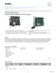
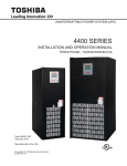
RM-2000-RTDW
Remote Monitor
User’s Guide
The RM-2000-RTDW motor-monitoring device can be used to monitor and/or control
SymCom’s Model 777 via an RS-485 Modbus network. Two form C output relays are
available for an RTD alarm and a warning alarm. Alarm and trip levels can be set for each
RTD to activate the RTD alarm and deactivate the 777 output relay respectively.
In addition, the RM-2000-RTDW has two inputs: one to connect to a ground-fault module
and the other for connection to a remote reset button.
A second communication port allows monitoring and control of up to 99 RM-2000-RTDW
devices from a computer with SymCom’s Solutions software, or a PLC, DCS, or SCADA
system. The RM-2000-RTDW is environmentally protected and can easily be mounted on
the front of a panel or MCC.
The RM-2000-RTDW displays the following
motor information:
• Real-time line currents, average current
and current unbalance
• Current to ground
• Line-to-line voltages, average voltage
and voltage unbalance
• Instantaneous power
• Power factor
• Last four faults
• All programmed 777 settings
• Remaining restart delay times
• 8 RTD temperatures
• Warning settings
The RM-2000-RTDW is also equipped with a
real-time clock, which allows access to the
following motor management information:
•
•
•
•
•
•
•
•
Total motor run-time (reset capable)
Time and date of last four faults, with voltage and current at time of trip
Time and date of last ten motor starts
Total number of motor restarts (reset capable)
Minimum time between any two starts with time and date
Run-time since last start (reset capable)
KWhs consumed
KVARs consumed
ne: 800.894.0412 - Fax: 888.723.4773 - Web: www.clrwtr.com - Email: info@clrwtr
PART I
INSTALLATION AND OPERATION
FEATURES
The RM-2000-RTDW is a motor management device used in conjunction with any
SymCom Model 777. The RM-2000-RTDW provides the following features:
Information Displayed
·
Run-Time Information: the RM-2000-RTDW can display all of the information
the Model 777 displays as well as information that the Model 777 maintains but
does not display, such as current unbalance, voltage unbalance and power
factor; see page 1 for a complete list of viewable parameters.
·
Real time clock: the RM-2000-RTDW has a real time clock so it can track
time-dependent data such as power draw (KW), energy consumption (KWH),
and run-hours.
·
Detailed information about fault conditions: the RM-2000-RTDW can store
information about power conditions just before the Model 777 tripped in
addition to the date and time of the fault.
·
Historical data: the RM-2000-RTDW can display historical data about the
motor being monitored by the Model 777 such as the total number of starts, the
number of trips, and the date and time of the last 10 starts.
Installation
·
Panel mounting: a model 777 is often mounted inside a motor control panel
and its display is not visible. The RM-2000-RTDW can be mounted on the
outside of the panel which allows all of the information from the Model 777 to
be displayed.
·
Remote mounting: the RM-2000-RTDW communicates with the Model 777 by
an RS485 cable which can be up to 4000 feet long. This allows the RM-2000RTDW to remotely monitor a Model 777.
·
Ease of installation: the RM-2000-RTDW only requires drilling 4 mounting
holes and punching out two 2” OD round holes using a standard knock out
punch or drilling 1 15/16” – 2 3/16” holes for the terminals to protrude through
to the inside of the panel.
ne: 800.894.0412 - Fax: 888.723.4773 - Web:
www.clrwtr.com - Email: info@clrwtr
4
INSTALLING THE RM-2000-RTDW
1. Attach the template drawing to the panel where the RM-2000-RTDW is to be mounted.
2. Take caution when drilling the holes to mount the RM-2000-RTDW. Use an 11/64” drill
bit for the four corner mounting screws. Drill a 1 15/16” – 2 3/16” hole for the terminals
to protrude through to the inside of the panel.
3. Verify the gasket is in place on the back of the RM-2000-RTDW. Attach the RM-2000RTDW to the panel using the four screws provided.
4. Run the appropriate wires to the back of the RM-2000-RTDW and terminate the wires
in the provided screw-type, depluggable connectors; see the wiring diagram on the
following page. This should include at least 120VAC control power, one set of
communication wires to the 777, and ground wire to case ground on the panel.
NOTE: When connecting a Benshaw remote RTD module, terminal A of the RTD
module must be connected to B1 of the RM-2000—B must be connected to A1.
5. It is important to have the A phase of the breaker connected to L1 on the 777, B phase
to L2 and C to L3. Equally important, is to have the A phase conductor through the A
phase hole, B through the B phase hole, and C through the C phase hole of the 777.
6. The 777, when used with the RM-2000-RTDW, should be connected according the
following wiring diagram.
INPUT VAC
L1 L2 L3
M
CONTROL POWER
240VAC OR LESS
MOMENTARY
START BUTTON
OR
CONTACT
GROUNDFAULT
MONITOR
STOP
M
Figure 1: Typical 777 Wiring Diagram
ne: 800.894.0412 - Fax: 888.723.4773 - Web:
www.clrwtr.com - Email: info@clrwtr
5
RTD
ALARM
NO2 C2
NC2
WARNING
ALARM
NO1 C1
NC1
L1
115VAC
REMOTE
RTD MODULE
L2
ADDRESS
#1
A1
RUN/RESET
REAL TIME
B1
FAULT
HISTORY
MODE
A2
B2
SCROLL
SETPOINT
A
B
24VDC
MODEL 777
ADDRESS #1
L1
L2
L3
NO
MODEL 777
OVERLOAD RELAY
MODE SELECT
#R U / ADDR
#RF
RD3
RD2
UCTD
RD1
GF
TC
RUN
CUB
LV
UC
HV
VUB
OC
MULT
C
RS-485 MODBUS
MASTER: PC, PLC,
DCS, or SCADA
RUN
SETUP
STOP
CHANGE
SETUP
ENTER
FAULT
COMM
STATUS
NC
A
B
S
V+
DISPLAY / PROGRAM
GF C
RR
R
R
+
784X
IND . CON
T. EQ.
GROUND FAULT
MONI TOR
L IST ED
RESET/
PROGRAM
REMOTE
RESET
MODEL RS485MS-2W
RTD
ALARM
NO2 C2
NC2
WARNING
ALARM
NO1 C1
NC1
L1
115VAC
REMOTE
RTD MODULE
L2
ADDRESS
#2
A1
A2
RUN/RESET
REAL TIME
B1
FAULT
HISTORY
B2
MODE
SCROLL
SETPOINT
A
B
24VDC
MODEL 777
ADDRESS #1
L1
MODE SELECT
#R U / ADDR
RD3
#RF
RD2
UCTD
RD1
GF
TC
RUN
CUB
LV
UC
HV
OC
VUB
MULT
L2
L3
NO
MODEL 777
OVERLOAD RELAY
C
RUN
SETUP
STOP
CHANGE
SETUP
ENTER
FAULT
COMM
STATUS
NC
DISPLAY / PROGRAM
+
A
B
S
V+
GF C
RR
R
R
784X
IND . CON
T. EQ.
GROUND FAULT
MONI TOR
L IST ED
RESET/
PROGRAM
REMOTE
RESET
MODEL RS485MS-2W
IMPORTANT! If using a Benshaw RTD module, terminal A must be
connected to B1 of the RM-2000, and B must be connected to A1.
UP TO 99
RM-2000s
NOTE: All network shielding connections are omitted for clarity.
Figure 2: RM-2000-RTDW Wiring Diagram
ne: 800.894.0412 - Fax: 888.723.4773 - Web:
www.clrwtr.com - Email: info@clrwtr
6
COMMUNICATIONS
A Model RS485MS-2W communications module is required to connect the Model 777 to
the RS-485 network. A shielded, twisted-pair cable connected to A and B of the RS485MS2W must be connected to Comm Port 1 (A1 & B1) on the back of the RM-2000-RTDW.
The RM-2000-RTDW has a second RS-485 port allowing connection to a network host,
such as a PLC, DCS, or SCADA system or a PC running Modbus master software such as
SymCom’s Solutions.
The network host is not required. If present, the network host must be connected to Comm
Port 2 at the connections labeled A2 and B2. The RM-2000-RTDW can be programmed as
device address A01– A99 and up to 99 RM-2000s or 777s can exist on the same network.
Unlike the Model 777, the RM-2000-RTDW can be programmed for 300, 600, 1200, 2400,
9600, 14400, 19200 or 28800 baud. It can use even, odd or no parity and have 1 or 2 stop
bits.
THE RS-485 NETWORK
Terminating Resistors
In the diagram on page 6 there are three RS-485 networks. Each of the two RM-2000RTDWs with their slave Model 777 and RTD module form a separate, independent RS-485
network. The third network links the host PC to the two RM-2000-RTDWs. Each
independent network may require terminating resistors and may require a ground
connection for the shield around the twisted pair cable.
If the length between the RM-2000-RTDW and the Model 777 exceeds 100 feet or if the
twisted pair cable is in a noisy environment, 120 terminating resistors should be
connected at both the RM-2000-RTDW (across A1 and B1) and also at the Model 777
(across A and B of the RS485MS-2W module). In addition, the shield of the twisted pair
cable should be tied to the RM-2000-RTDW’s ground connection (labeled GND) with a
single 100 resistor.
Unlike the port-powered RS-232 to RS-485 converter, the transceiver inside the RM-2000RTDW is capable of supplying enough current to operate the RS-485 network, even with
terminating resistors installed. If you are unsure if terminating resistors are required, it
would be good to use them. The RM-2000-RTDW to host is a separate network. It may
require separate terminating resistors and ground connection.
Existing Network Installations
If an RM-2000-RTDW is being added to a Model 777 in an existing network, the RM-2000’s
network address must be set to the existing Model 777’s address and the Model 777’s
address must be set to match the overload address of the RM-2000-RTDW.
The RM-2000-RTDW will map the data from the Model 777 into the same register locations
as the Model 777, so the RM-2000-RTDW will respond just like the Model 777 as far as the
Modbus Master software application is concerned. The Modbus Master software will not
have to be reprogrammed to communicate with the RM-2000-RTDW, unless the additional
information from the RM-2000-RTDW is desired.
ne: 800.894.0412 - Fax: 888.723.4773 - Web:
www.clrwtr.com - Email: info@clrwtr
7
OPERATING THE RM-2000-RTDW
RM-2000-RTDW information and functions are divided into five modes:
•
•
•
•
•
REAL TIME
FAULT HISTORY
SETPOINT
SETUP
CHANGE SETUP (key switch or jumper required)
Press the [MODE] button to switch between these modes. An LED on the left side of the
RM-2000-RTDW indicates which mode is selected.
Within any mode, the [SCROLL DOWN] and [SCROLL UP] buttons will change the
information being displayed.
Only the SETPOINT and SETUP modes allow setting changes. The CHANGE SETUP LED
is lit along with the SETPOINT or SETUP LED when a mode setting is ready to be
changed. The [CHANGE SETUP DOWN] and the [CHANGE SETUP UP] buttons
decrement and increment the value of a setup option. When the desired value is displayed,
press [ENTER] to save the setting.
The RM-2000-RTDW’s [RUN/RESET] button is non-functioning and will not start the
motor. The [STOP] button will de-energize the Model 777’s control relay provided the
Start/Stop option is enabled in the SETUP mode (“EN.START/STOP: YES”). Set the option
to “NO” to disable the [STOP] button.
MODES
REAL TIME: displays all real-time information as well as temperature from RTDs,
calculated power factor and power consumption, and total number of starts and trips.
FAULT HISTORY: displays detailed information about the last 4 faults that caused the
Model 777 to trip. It also displays the last 10 starts, the length of time the motor has been
running, and the date, time and length of the minimum time the motor was off.
SETPOINT: displays the parameters programmed into the Model 777. Examples of these
parameters would include the overcurrent and undercurrent limits (OC and UC), the current
unbalance (CUB) limit, etc., programmed into the Model 777.
SETUP: displays the parameters that affect the operation of the RM-2000-RTDW, such as
real-time clock settings (month, day, hour, etc.), the network host communications
parameters, the voltage multiplier and others.
CHANGE SETUP: allows you to change the parameters that are displayed in the SETUP
and SETPOINT modes. A jumper* connected between K1 and K2 on the back of the
RM-2000-RTDW is required to enter this mode. The CHANGE SETUP mode will be
skipped when scrolling through the modes if the jumper is not in place.
*Note: If desired, a key-switch can be installed in place of the jumper to allow only
authorized personnel to make system/setting changes.
ne: 800.894.0412 - Fax: 888.723.4773 - Web:
www.clrwtr.com - Email: info@clrwtr
8
LEDs
Eight LEDs indicate the status of the RM-2000-RTDW:
• five red LED’s on the left side indicate the display mode
• the green COMM STATUS LED on the lower right indicates the communication status
between the RM-2000-RTDW and the Model 777 and RTD module. If the COMM
STATUS LED is:
On – communication is good with both slaves
Blinking – communication has been lost with one slave
Off – no communication with the either slave is detected
• The green RUN LED on the upper right indicates the motor is drawing current.
• A solid red FAULT LED indicates the Model 777 has tripped on a fault and is either in
manual reset mode or the Model 777 is going through restart delay RD2 or RD3.
When a fault occurs, the RM-2000-RTDW automatically switches to the FAULT
HISTORY mode and displays FAULT 1—the most recent fault. The RM-2000-RTDW
will not switch to the FAULT HISTORY mode if it is currently in the CHANGE SETUP
mode.
A blinking red FAULT LED indicates the Model 777 has a pending fault. If the motor is
not running, this may be a condition that is preventing the Model 777 from starting,
such as high or low voltage. Look at the pending fault screen in the REAL TIME mode
to view the existing fault condition.
TROUBLESHOOTING COMMUNICATION LOSS
If the RM-2000-RTDW loses communications with the Model 777 or the RTD module, the
green COMM STATUS LED will blink. If communication is lost with both devices, the LED
will be off. Any screens with data read from these devices will contain asterisks. For
example, the screen showing 3-phase voltages and the average voltage will look like:
V a b =
∗
V b c =
∗
V a c =
∗
V a v g =
∗
Things to look for:
1) Verify the Model 777 has power on lines L1 and L2.
2) Verify the Model 777 is programmed with the correct address.
3) Verify the Remote RTD Module is programmed with the correct address.
4) Verify the RS-485 cable connects A1 of the RM-2000-RTDW to A of the Model RS485MS-2W module and B1 to B.
5) If using a Benshaw remote RTD module, verify terminal A of the RTD module is
connected to B1 of the RM-2000, and B is connected to A1.
6) If using an older communications module, Model RS485MS, verify that A is shorted to Y
and B is shorted to Z.
7) Verify continuity of the RS-485 cable with an ohmmeter (NOTE: test for continuity
only when the RS-485 circuit is de-energized!).
ne: 800.894.0412 - Fax: 888.723.4773 - Web:
www.clrwtr.com - Email: info@clrwtr
9
PART II - SCREEN INFORMATION
REAL TIME MODE
The REAL TIME mode displays real-time information as well as calculated power factor
and power consumption, and total number of starts and trips. By scrolling through the
REAL TIME mode the following screens can be viewed:
Current and Voltage Information - displays line-to-line voltages and phase currents.
I =
5 . 5 0
5 . 6 5
5 . 3 5
V =
2 3 0
2 3 5
2 2 5
Line Currents and Average Current
I a =
5 . 5 0
I b =
5 . 6 5
I c =
5 . 3 5
I a v g =
5 . 5 0
Line-to-Line Voltages and Average Voltage
V a b =
2 3 0
V b c =
2 3 5
V a c =
2 2 5
V a v g =
2 3 0
If potential transformers (PTs) are used with the 777, the voltage multiplier (“VOLTAGE
MULT” in the SETUP menu) should be programmed with a voltage multiplier equal to the
PT ratio. The voltage displayed on the RM-2000-RTDW will be higher than the voltage
displayed on the 777, but will be consistent with the actual voltage.
Calculated Current and Voltage Unbalance
C U R R .
U N B A L A N C E =
3 %
V O L T .
U N B A L A N C E =
2 %
Restart delays RD1, RD2 and RD3
R E S . D E L A Y
R D 2 =
0 M
R D 1 =
R D 3 =
0 M
0 S
RD1: power-up and rapid-cycle delay
RD2: restart delay after all faults except undercurrent
RD3: restart delay after an undercurrent fault
NOTE: This screen show the time remaining for each restart delay, not the
setpoint value programmed into the Model 777.
Ground Fault Current: for a motor, this value would likely represent the current leaking
through the insulation of one or more phases.
G R O U N D
F A U L T
0 . 1 0
C U R R E N T
A M P S
ne: 800.894.0412 - Fax: 888.723.4773 - Web:
www.clrwtr.com - Email: info@clrwtr
10
Accumulated Hours and Energy
A C C .
H O U R S =
0 . 1
E N E R G Y - K W H =
3 . 0
The Accumulated Hours is the number of hours the Model 777 has detected current flow
and the Energy-kWh (or Energy-MWh) is the calculated energy consumed during these
hours. The information displayed is updated every minute.
The Accumulated information is stored in memory and will not be lost if the RM-2000RTDW loses power. The values can be reset to zero with the CLEAR HISTORY option in
the CHANGE SETUP mode.
Number of Starts and Trips - values can be reset to zero by the CLEAR HISTORY option
in the CHANGE SETUP mode.
N O .
S T A R T S =
5
N O .
T R I P S
2
=
Average Voltage, Current and Power Factor
V A V =
2 3 0
P O W E R
F A C T O R
I A V G =
5 . 5 0
=
0 . 9 6
If connected to a Model 601, be sure to set the Model to 601 in the CHANGE SETUP
mode. This allows the Frequency information of the Model 601 to be displayed on this
screen instead of Average Voltage and Average Current.
Power and KVARS - displays consumed motor power in kW and reactive power in kVARS.
P O W E R ( K W ) =
1 . 2 1
K V A R S
0 . 6 4
=
RTD Inputs - displays temperature measurements from the 8 RTDs.
R T D
# 1
=
7 0 ° C
R T D
# 2
=
1 0 0 ° C
Input Status Bits - displays the status of the RM-2000-RTDW input channels.
I n p u t
B i
t s = 7 6 5 4 3 2 1 0
S t a t u s = 0 0 0 0 0 0 0 0
This screen is only visible if the I/O Screens are set to ON (CHANGE SETUP mode).
Warning Information
W A R N I N G S
O C
U C
V U B
C U B
H V
L V
The warning screen displays each of the present warning conditions based on the
WarnLevels set in the SETUP mode. If no warning conditions exist, “NONE” will be
displayed. If any warning condition is present, the WARNING ALARM relay is energized.
ne: 800.894.0412 - Fax: 888.723.4773 - Web:
www.clrwtr.com - Email: info@clrwtr
11
Pending Fault Information
P E N D I N G
F A U L T
N O N E
The Pending Fault screen will display up to three pending faults the Model 777 has
sensed. The RM-2000-RTDW’s FAULT LED will blink anytime a pending fault condition
exists. If the Model 777 is in a de-energized state, the pending fault identifies present
conditions that will prevent the Model 777 from starting. The RM-2000-RTDW uses the
following codes to represent the faults:
Fault Code
OC
I SP
V SP
CUB
RP
UC
VUB
HV
LV
GF
Fault Description
Overcurrent
Single-phase current
Single-phase voltage
Current unbalance
Reverse phase
Undercurrent
Voltage unbalance
High voltage
Low voltage
Ground fault
FAULT HISTORY MODE
Fault Information
The RM-2000-RTDW will store detailed information about the last 4 faults. The fault
information may be cleared by the CLEAR FAULTS option in the CHANGE SETUP mode.
NOTE: When a fault occurs the RM-2000-RTDW will jump to the FAULT HISTORY
mode and display the Fault 1 screen. To return to the previous mode, press ENTER.
Fault Description, Date & Time - fault #1 is the most recent, fault #4 is the oldest.
F A U L T
1
[ C U R R
2 0 0 7 / 0 3 / 1 4
U N B A L ]
0 2 : 5 5 : 2 6 P
Fault Currents - displays phase current measurements just before the fault.
F A U L T
1
5 . 5 0
C U R R E N T S =
5 . 6 5
5 . 3 5
Fault Voltages - displays voltage measurements just before the fault.
F A U L T
1
2 3 0
V O L T A G E S =
2 3 5
2 2 5
Fault Current Unbalance and Average Current - reported just before the fault.
F A U L T
1
A V E R A G E
C . U N B A L =
C U R R . =
3 %
5 . 5 0
ne: 800.894.0412 - Fax: 888.723.4773 - Web:
www.clrwtr.com - Email: info@clrwtr
12
Fault Voltage Unbalance and Average Voltage - reported just before the fault.
F A U L T
1
V . U N B A L =
A V E R A G E
3 %
V O L T . =
2 3 0
Fault Ground Fault Current - reported just before the fault.
F A U L T
1
G R O U N D
[ C U R R
U N B A L ]
F A U L T =
1 . 2
A
Event Information
The RM-2000-RTDW will store the time of the last 10 events: motor starts, motor stops,
RM-2000 power on, RM-2000 power loss, communication on, communication loss. Event
information can be cleared by the CLEAR EVENTS option in the CHANGE SETUP mode.
Event Description Date & Time - event 1 is the most recent, event 10 the oldest.
E V E N T
1 :
M T R
2 0 0 7 / 0 3 / 1 5
S T A R T
0 7 : 5 7 : 2 3 P
Last Start - date and time of the last motor start.
L A S T
S T A R T :
2 0 0 7 / 0 3 / 1 5
0 7 : 5 7 : 2 3 P
Run Time - length of time between the last motor start and stop.
R U N
2 0
T I M E :
H R S
1
2 8
M I N
5 4
D A
S E C
Minimum Off Time
Date of Minimum Off Time - date and time of the start following the Minimum Off Time.
D A T E
O F
M I N
2 0 0 7 / 0 3 / 1 1
O F F
T I M E
1 0 : 2 5 : 5 3 P
Minimum Off Time - the minimum length of time the motor was off.
M I N
O F F
T I M E :
1
M I N
2
S E C
Very short times may signify a motor was not allowed to cool down before restarting
indicating a programming error or operator override.
NOTE: The Last Start, Run Time, Date of Minimum Off Time and Minimum Off time
screens can be cleared by the CLEAR MIN OFF option in the CHANGE SETUP mode.
Minimum Time Before the Next Start
M I N
T I M E
S T A R T :
B E F O R E
N E X T
0
S E C
Based on the Minimum Time Between Starts setting (in the SETUP mode), this screen
displays the time remaining before the motor can be started again.
ne: 800.894.0412 - Fax: 888.723.4773 - Web:
www.clrwtr.com - Email: info@clrwtr
13
SETPOINT MODE
The SETPOINT mode displays the parameters that are programmed into the Model 777.
Each setting can be viewed and changed using the RM-2000-RTDW, without interrupting
the Model 777’s control relay.
Current Limits – overload and underload limits.
O V E R
C U R R .
:
1 6 . 0
U N D E R
C U R R .
:
1 0 . 0
Voltage Limits - HV and LV settings.
O V E R
V O L T .
:
2 7 2
U N D E R
V O L T .
:
2 0 7
C U R R .
U N B A L ;
7 %
V O L T .
U N B A L :
5 %
Unbalance Limits - CUB and VUB settings.
Current Multiplier and Ground Fault Limit - MULT and GF settings.
C U R R .
G R N D
M U L T :
F A U L T :
5
1 . 2 0
A
Restart Delays - RD1, RD2, RD3 settings.
R E S
D E L A Y
R D 1 :
0 S
R D 2 :
3 0 M
R D 3 :
2 0 M
RD1: rapid-cycle delay
RD2: restart delay after all faults except undercurrent
RD3: restart delay after an undercurrent fault
NOTE: This screen shows the setpoint for each restart delay, not the time remaining.
Trip Class and Under Current Trip Delay - TC and UCTD settings.
T R I P
U C
C L A S S :
T R I P
D E L A Y :
1 0
5 S
Number of Restart Attempts after an Undercurrent Fault - #RU setting.
N U M B E R
O N
O F
U N D E R
R E S T A R T S
C U R R :
0
Number of Restart Attempts after any other Fault - #RF setting.
N U M B E R
O T H E R
O F
R E S T A R T S
F A U L T S :
0
ne: 800.894.0412 - Fax: 888.723.4773 - Web:
www.clrwtr.com - Email: info@clrwtr
14
Power Limits - High and low kW settings.
H I G H
L O W
K W :
0 . 5 0
K W :
0 . 5 0
Message Builder - read/write data to 777*.
V a l u e =
0 0 0 0 h =
A d d r =
0 0 6 5 H
F F
S K I P
The message builder screen allows you to read and write 777 information.
Writing: the value to be written is displayed as both hexadecimal and decimal numbers.
Set the proper address, scroll to show “WRITE,” and press [ENTER].
Reading: set the address, show “READ,” press [ENTER]—the value will be displayed,
*Please refer to SymCom’s 777 Programming Guide for more information.
Command Line
S e n d
c o m m a n d :
F A U L T
R E L A Y
O F F
The command line allows you to do several things:
• Turn off/on slave communication watchdog
• Send an off or reset command to the 777
• Lock/unlock network programming—prevents/allows 777 parameter
setting changes
• Clear run hours
• Clear last fault
Model and Software
M o d e l
S o f
:
t w a r e
7 7 7
R e v :
2 5 . 3 8
SETUP MODE
The SETUP mode displays parameters that affect the operation of the RM-2000-RTDW.
Real Time Clock
Clock Date Settings - real-time clock date settings.
C L O C K
Y E A R : 2 0 0 7
M O N T H : 0 3
D A Y : 1 4
Clock Time Settings - real-time clock time settings.
H O U R : 0 1 P
M I N U T E : 5 9
( A M / P M )
S E C : 2 6
The time can be displayed in 24 hour values by changing (AM/PM) to (24HR).
ne: 800.894.0412 - Fax: 888.723.4773 - Web:
www.clrwtr.com - Email: info@clrwtr
15
777 Comm Port (Port 1, A1 & B1)
777 Port Address
O V E R L O A D
O V R L D
( P O R T
A D D R :
1 )
A 0 0 1
The Overload Address must match the address programmed into the 777.
777 Port Communication Parameters
O V R L O A D
B A U D :
P A R I T Y : E
9 6 0 0
S T O P : 1
To communicate with the 777, the RM-2000-RTDW must be set to 9600 baud, even
parity, with one stop bit.
Network Comm Port (Port 2, A2 & B2)
Network Port Address
N E T W O R K
N E T W O R K
( P O R T
A D D R :
2 )
A 0 2 6
The host network allows communication between an RM-2000-RTDW and a PC with
SymCom’s Solutions software, or a PLC, DCS, or SCADA system. Up to 99 RM-2000s
can exist on this network; thus, the network address can be set from A001–A099.
Network Port Communication Parameters
N E T W O R K
P A R I T Y : N
B A U D :
9 6 0 0
S T O P : 1
The RM-2000-RTDW can communicate on a host network using 300, 600, 1200, 2400,
9600, 14400, 19200 or 28800 baud; even, odd or no parity; and 0, 1 or 2 stop bits.
Network Watchdog
N e t w o r k
W a t c h d o g
D I S A B L E D
An upstream communication watchdog occurs when no upstream messages are
received for 10 seconds. Another watchdog will not occur, and no watchdog actions will
be taken again until communication is re-established and then lost again for 10 seconds.
The network watchdog can be disabled—meaning there will be no action taken if a
network watchdog occurs—or two network watchdog functions can be utilized.
1) Send OFF – when an upstream communication watchdog occurs, the RM-2000
will send an off command to the overload, de-energizing the 777’s output relay.
2) Send RHWD – when an upstream communication watchdog occurs, the RM-2000
will send a remote host watchdog command to the overload.
ne: 800.894.0412 - Fax: 888.723.4773 - Web:
www.clrwtr.com - Email: info@clrwtr
16
Remote RTD Module Comm Port (Port 1, A1 & B1)
Remote RTD Module Address - can be set from 16 to 23.
R E M O T E
R T D
R T D
( P O R T
A D D R E S S :
1 )
1 6
The RTD Address must match the address selected on the RTD module.
Remote RTD Module Communication Parameters
R T D
B A U D :
1 9 2 0 0
P A R I T Y : N
S T O P : 1
The RM-2000-RTDW can communicate with an RTD module using 300, 600, 1200,
2400, 9600, 14400, 19200 or 28800 baud; even, odd or no parity; and 0, 1 or 2 stop bits.
If using a Benshaw Remote RTD module, select 19200 baud, no parity, and 1 stop bit.
Model and Voltage Multiplier
M O D E L :
7 7 7
V O L T A G E
M U L T :
1
Model Number
The Model Number setting should match the model number of the 777 monitored by the
RM-2000.
Voltage Multipllier
Voltage Multiplier should be set to 1 unless the 777 is powered by potential transformers
(PTs). This multiplier is used to scale the voltage readings up to the actual line voltages
being monitored.
Model 777 Power Factor Correction
M O D E L
O N L Y
7 7 7 M V
1
P . T .
W I T H
?
:
N O
If the Model 777-MV (Medium Voltage) is installed with only ONE potential transformer
(PT), set this function to YES—the RM-2000-RTDW will adjust the power factor to
correct the Power, kVARs, and Energy Usage values. Be sure to check the Model 777MV installation instructions to keep the proper relationship between PT and CT
connections.
LCD Control and UC Alarm Control
A U T O
A L A R M
L C D
D I M
:
Y E S
O N
U / C
:
Y E S
LCD Control
If the Auto LCD Dim option is set to NO, the backlighting of the LCD will remain on all the
time. If the option is set to YES, the backlighting will automatically turn off 2 minutes after
the last button is pressed.
UC Alarm Control
This setting is commonly used in pumping applications. If a well runs dry, the Model 777
will shut down the motor because of an undercurrent condition. Since this may occur
frequently in pumping applications, the undercurrent faults can fill up the last four faults
of the RM-2000-RTDW. If you do not want the fault screen to pop up on the RM-2000RTDW when an undercurrent fault is detected, set this field to “NO”. This allows the last
four faults to keep track of other, unexpected faults.
ne: 800.894.0412 - Fax: 888.723.4773 - Web:
www.clrwtr.com - Email: info@clrwtr
17
Starting with Voltage Errors*
I F
S T A R T I N G
E R R O R S :
W / V O L T .
S E N D
O F F
This setting controls how a [RUN/RESET] button* is handled when the Model 777 is
trying to start, but voltage errors are present.
If a motor has been shut down and the Model 777 detects a voltage error—overvoltage,
undervoltage, reverse phase, or voltage unbalance—the Model 777 will not close its
control relay until the voltage fault goes away.
When “If Starting w/ Volt. Errors:” is set to SEND OFF—if the [RUN/RESET] button is
pressed while the voltage faults are present—the RM-2000-RTDW will send an OFF
command instead of a START command. This prevents the Model 777 from starting,
even after the voltage fault goes away. The RM-2000-RTDW displays a message to
report this change for about two seconds. The [RUN/RESET] button must be pressed
again after the voltage faults are cleared to make the motor start.
When this setting is “SEND ON” and you push the [RUN/RESET] button, a START
command will be sent to the Model 777. When the Model 777 receives a START
command, it will restart the control contacts as soon as the voltage fault goes away.
*The [RUN/RESET] button is currently non-functioning on the RM-2000-RTDW.
Therefore, the Starting with Voltage Errors screen and functionality is not applicable.
Type of Events to Track
L O G
L O G
L O G
M T R
S T A R T S :
Y E S
M T R
S T O P S
:
Y E S
R M
P W R
O N
:
N O
R M
P W R
L O S :
N O
C O M M
O N
:
N O
C O M M
L O S S
:
N O
The RM-2000-RTDW will track up to 10 events with the date and time of each event.
Specify YES or NO for each of the events according to your system preferences.
RTD Limits Settings - RTD trip and alarm limits (up to 8 RTDs).
R T D
# 1
T R I P :
1 1 0 ° C
A L A R M :
9 0 ° C
The temperature measurements from a connected RTD module can be read by the RM2000-RTDW. Alarm and trip limits can be entered into the RM-2000-RTDW (40°– 200°C
or OFF) for each of the 8 RTDs.
RTD Trip level is exceeded = 777 output relay de-energizes (NO contact opens)
RTD Alarm level is exceeded = RTD ALARM relay energizes (NO contact closes)
RTD Network Watchdog
If the RM-2000-RTDW loses communication with the RTD for a period of 10 seconds,
the 777’s output relay will open if any RTD trip level is set (not off) and the RTD ALARM
relay will close if any RTD alarm level is set.
ne: 800.894.0412 - Fax: 888.723.4773 - Web:
www.clrwtr.com - Email: info@clrwtr
18
Minimum Time Between Starts
M I N I M U M
T I M E
S T A R T S :
3 0
B E T W E E N
M I N U T E S
The Minimum Time Between Starts (MTBS) can be set from 0–60 Minutes. Each time
the motor starts, the Minimum Time Before Next Start (FAULT HISTORY mode) begins
counting down from the MTBS setting. The RM-2000-RTDW will prevent the motor from
starting again until the timer expires. The MTBS cannot be overridden by pressing the
remote reset button unless the key switch is on (K1 and K2 are shorted).
Motor Nameplate Volts/Amps - nominal voltage and full load current of the motor.
N o m . V o l
t a g e :
x x x x x V
F L A
r e n t
x x x . x A
C u r
:
The UC/OC and LV/HV warning levels are based on these two parameters.
Warning Levels - levels to control the WARNING relay.
F L A
C u r
r e n t
:
U C W r n : x x x x %
F L A
C u r
r e n t
O C W r n : x x x x %
N o m .
V o l
V o l
:
x x x . x A
x x x . x A
x x x . x A
t a g e :
x x x x x V
=
x x x x x V
t a g e :
x x x x x V
H V W r n : x x x x %
C U B
=
=
L V W r n : x x x x %
N o m .
x x x . x A
S e t P t
:
=
x x x x x V
x x x %
C U B W r n : x x x x % = x x x x x x %
V U B
S e t P t
:
x x x %
V U B W r n : x x x x % = x x x x x x %
Warning levels can be set as a percentage of the programmed limits for nominal voltage,
full load current, current unbalance, and voltage unbalance (the setpoints for each
parameter are displayed but cannot be changed on these screens). Each warning level
can be set from OFF to 1275% in 5% increments and the screen will automatically show
the warning level in amps, volts and percentages to simplify setup.
The WARNING relay functions as follows:
– If the average of the measured phase currents drops below the undercurrent warn
level (UCWrn), the WARNING relay energizes.
– If any measured phase current exceed the overcurrent warn level (OCWrn), the
WARNING relay energizes.
– If the average measured voltage is greater than the high voltage warn level
(HVWrn), or less than the low voltage warn level (LVWrn), the WARNING relay is
energized.
– If either the current unbalance (CUBWrn) or voltage unbalance (VUBWrn) warn
level is exceeded, the WARNING relay is energized.
ne: 800.894.0412 - Fax: 888.723.4773 - Web:
www.clrwtr.com - Email: info@clrwtr
19
Output Relay Status - displays the status of the RM-2000-RTDW output relays.
R E L A Y
A :
O F F
R E L A Y
B :
O F F
This screen is only visible if the I/O Screens are set to ON.
I/O Screens - displays/hides the input and output relay status screens.
I
/ O
S c r e e n s :
O F F
Slave and RTD Watchdog Commands
S l v C o m W d : W r n R l y = O F F
R T D : R l y = O F F
T r p = O F F
This screen allows you to control the WARNING, RTD and the 777 relays in the event of
a communication loss. The relays function as follows:
– SlvComWd:WrnRly = ON: the WARNING relay will energize if the RM-2000-RTDW
loses communication with the 777. WrnRly = OFF: no action.
– RTD:Rly = ON: the RTD relay will energize if the RM-2000-RTDW loses
communication with the RTD module. RTD:Rly = OFF: no action.
– RTD:Trp = ON: the 777 will trip (relay de-energizes) if the RM-2000-RTDW loses
communication with the RTD module. RTD:TRP = OFF: no action.
Clear History & Faults
C L E A R
H I S T O R Y :
N O
C L E A R
F A U L T S
N O
:
In the CHANGE SETUP mode, this screen allows you to clear the motor’s history
information that is displayed in the REAL TIME mode and you can clear the fault
information displayed in the FAULT HISTORY mode.
Clear Events & Minimum Off Time
C L E A R
E V E N T S
C L E A R
M I N
:
N O
O F F :
N O
In the CHANGE SETUP mode, CLEAR EVENTS will allow you to clear the 10 starting
events. The CLEAR MIN OFF option allows you to clear the date and time of last start,
the run time, the date & time of the Minimum Off Time, and the Minimum Off time.
Change Option & Enable Start Stop
C H A N G E
S E T U P
:
Y E S
E N . S T A R T / S T O P :
Y E S
This screen will display whether changes are permitted by the RM-2000-RTDW.
If the Change Setup option displays NO, it is not possible to enter the CHANGE SETUP
mode. The only way to set the Change Setup option to YES is to short K1 and K2.
The RM-2000-RTDW’s [RUN/RESET] button is disabled. Setting En. Start/Stop to YES
only enables the Stop button and allows you to send an off command to the 777.
ne: 800.894.0412 - Fax: 888.723.4773 - Web:
www.clrwtr.com - Email: info@clrwtr
20
Firmware Version
R M - 2 0 0 0 - R T D W
V e r s
i o n
3 . 1 5
This screen is only displayed in the SETUP mode. It displays the firmware version
number and any options that the firmware is configured to control.
CHANGE SETUP MODE
The CHANGE SETUP* mode allows changes to be made to the SETPOINT and SETUP
information. To change SETPOINT parameters, press the MODE button until both
SETPOINT and CHANGE SETUP LEDs illuminate. To change SETUP parameters, press
the MODE button until SETUP and CHANGE SETUP LEDs illuminate.
In the CHANGE SETUP mode, a “>” and “<” will indicate the selected parameter. Use the
[SCROLL UP] and [SCROLL DOWN] buttons to move through the parameters. To change
the value or a parameter, press the CHANGE SETUP [UP] and [DOWN] buttons. When a
value is changed a “*” will appear. To save the displayed value, press [ENTER].
* Note: K1 and K2 must be shorted (key switch on).
ne: 800.894.0412 - Fax: 888.723.4773 - Web:
www.clrwtr.com - Email: info@clrwtr
21
RM-2000-RTDW SPECIFICATIONS
Control Voltage
Transient Protection
Power Consumption
Communication
Baud Rate
Setup
Protocol
Serial Interface
Available Addresses
Real-Time Clock
Battery Back-up Life
Last Fault Memory
Output Relays
Contact Material
Pilot Duty Rating
General Purpose Rating
Environment
Class of Protection
Ambient Operating Temperature
Ambient Storage Temperature
Humidity
Enclosure
Dimensions
Weight
Material
Display
Size
Lighting
Keypad
Mechanical Life
Overlay Material
UV Exposure w/out Degradation
Terminal
Torque
115VAC ±10%, 50 or 60Hz
2500V for 10ms
3 Watts (max.)
MS 777
RTD Module
9600
300-28800
None, Odd, or Even
Even Parity,
1 Stop Bit
Parity, 1 or 2 Stop Bits
Modbus RTU
Modbus RTU
RS485MS-2W
RS485MS-2W
A01-A99
16-23
PC, PLC, etc.
300-28800
None, Odd, or Even
Parity, 1 or 2 Stop Bits
Modbus RTU
RS485MS-2W
A01-A99
10 years @ 25°C without external power
Stores up to 4 faults with time and date stamp, includes voltages
and currents at time of trip
Two independent electro-mechanical Form C (SPDT)
Silver/Tin Oxide
240VA @ 120VAC
5A @ 120VAC
NEMA 3R
-20° to 70°C
-30° to 70°C
Up to 85%, non-condensing
6.1” L x 6.5” W x 1.1” D
1.2 lbs.
Black polycarbonate
Liquid crystal with extended temperature range
2 rows x 20 characters
LED backlight
Eight 0.5” stainless steel dome buttons for tactile feedback
50,000 actuations
Polyester
2000 hrs.
Depluggable terminal block
3 in.-lbs. max.
ne: 800.894.0412 - Fax: 888.723.4773 - Web:
www.clrwtr.com - Email: info@clrwtr
22