1
Wireless Routers
Wireless Routers
Mobile Router
GPRS / EDGE
Broadband Router
UMTS HSDPA / HSUPA
MULT
eNET Wireless Routers
User Manual
English
Version 1.0
March 2008
1
Manual
Wireless Routers
Document Scope
This manual describes how to install, configure and operate the Multenet Wireless Routers.
For updated product features, refer to our website at www.multenet.com
Revision History
Revision No
Changes
1.0
First release
Data, Illustrations, Alterations
The data and illustrations found in this document are not binding. We reserve the right to
modify our products in line with our policy of continuous product development. The information
in this document is subject to change without notice and should not be construed as a
commitment by Multenet.
Multenet assumes no responsibility for any errors that may appear in this document. If you
have any suggestions for improvement or amendment, or have found errors in this publication,
please notify us through your distributor or email [email protected]
Trademarks
EtherPAD and PocketPAD are registered Trademarks of Multenet. Internet Explorer, Windows
95/98/2000/NT/XP are registered trademarks of Microsoft Corporation. Ethernet is a trademark
of XEROX Corporation. Modbus is a trademark of Schneider Electric, Inc.
Copyright 2008 Multenet All rights reserved.
Contact details:
Multenet Technologies (Pty) Ltd.
P O Box 7155, Stellenbosch, 7599
The Vineyard Centre, Adam Tas Road,
Stellenbosch, 7600
Sales Email : [email protected]
Technical Support Email : [email protected]
Website : http://www.multenet.com
2
Manual
Contents
INTRODUCTION
Introduction to the Wireless Routers
Wireless Connectivity
GPRS
EDGE
UMTS HSDPA
HSUPA
Wireless Routers
Mobile Router
Broadband Router
Product Features
Security
Firmware Updates
GETTING STARTED
Inserting SIM cards
Attaching the Antenna
10/100 Base-T Ethernet Network Connection
Serial Port Connection
Configuration of the Wireless Router
Discovering Multenet Devices
CONFIGURATION
Configuration Overview
Web Browser Configuration
Requirements
Check your web browser proxy settings
Open Web configuration
Log into Web Configuration
Home
Management
Security
System Information
Date and Time
Mobile
Networking
Ethernet Parameters
PPP (Point-to-Point Tunnelling Protocol)
Routing
VPN
DNS (Domain Name Server)
SNMP (Simple Network Management Protocol)
Port Forwarding
DHCP
Wireless Routers
6
7
7
7
7
7
7
7
7
7
8
9
9
10
11
11
12
12
12
12
15
16
17
17
17
17
17
18
19
19
19
19
21
22
22
23
31
32
34
34
35
36
3
Manual
Wireless Routers
Firewalling
Serial
Port Settings
Applications
Configuration File Upload
Monitoring and Support
Monitoring
PPP Connection
Routing Table
Firewall Log
Example of Firewall Log
DHCP Server Log
Connection List
Mobile Network
Support
Config Info
Config File
System Log
Contact Us
Tools
Ping
Traceroute
SMS Services
36
38
38
40
46
47
48
48
50
51
51
51
52
52
54
54
55
56
57
58
58
58
59
UPGRADING
Firmware upgrade
TROUBLESHOOTING
Verifying MAC Addresses
Ping
ARP
Traceroute
Telnet
Web Browser Proxy Settings
Recovering from a Lost Password
System
Serial Interface
Network Interface - 10/100 Base-T
GSM
Mobile Network
61
62
62
63
63
63
64
64
66
67
67
67
67
68
4
Manual
Wireless Routers
APPENDIX
Interface Pin-outs
Network Interface
Serial Interface
RS-422 Serial Interface Pin-out
Cables
Crossed Serial Cable
Full Crossed Serial Cable
Null-Modem Crossed Serial Cable
Straight Serial Cable
69
71
71
71
72
73
73
73
74
74
NOTES
75
5
Manual
Wireless Routers
INTRODUCTION
The chapter provides information on functionality and provides an overview of wireless
communication technologies.
6
Introduction
Introduction to the Wireless Routers
Wireless Routers
Wireless Connectivity
To determine which wireless technology is best suited for your application, the following
guideline will give you some indication of the differences in these technologies.
GPRS
GPRS is a basic low speed GSM data service offered by most GSM operators. It has a
basic upload speed of 11kb/s and a download speed of around 44kb/s. Although GPRS is
very reliable and almost universally available where GSM exists, it has a major drawback of
relatively long latency times with an average latency of around 700 – 900mS. GPRS is ideal
for telemetry applications (meter reading, remote monitoring of devices etc.) or low speed
transaction based systems such as ATM’s but it is unsuitable for video links.
EDGE
EDGE is an enhancement to GPRS which is effectively four times the speed in both the
upload and download directions (i.e. 176Kb/s down and 44kb/s up). It is however not as widely
available as GPRS, but is capable of providing low to medium grade streaming video due to
the higher bandwidth and lower latency.
UMTS HSDPA
HSDPA is an advanced technology which provides very high speed wireless mobile data.
Current speeds are 7.2Mb/s in the download direction depending on the network’s capabilities.
Because of the above, HSDPA is ideal for almost all applications which need reliable, high
speed networking. Applications include remote signage high quality CCTV and provision of
internet access to areas with no access to wired services.
HSUPA
HSUPA is the latest release of high speed wireless network which offers significantly improved
uplink speeds as denoted by the ‘U’ in the name. Uplink intensive applications such as CCTV
will benefit considerably from this technology.
Wireless Routers
Mobile Router
The Mobile Router is capable of connecting to GSM/GPRS/EDGE networks. Typical applications are where reliability is important, but high speed is not a priority such as ATM machines,
credit cards authorizations and telemetry.
Broadband Router
The Broadband Router is capable of connecting to UMTS HSDPA / HSUPA networks. Typical
applications include remote office connectivity and CCTV video streaming.
7
Introduction
Wireless Routers
Product Features
The Wireless Routers have one RS-232/422/485 Serial interfaces, a integrated EDGE or
HSDPA modem depending on model, dual SIM slots and a single 10/100 Base-T Ethernet
interface.
A Wireless Router is capable of connecting a number of Ethernet devices via GSM/GPRS/
EDGE networks on the Mobile Router, or UMTS/HSDPA networks on the Broadband Router.
With always–on and DUAL SIM card technology they provide easy to deploy access to central
servers and the Internet via GSM networks. The Wireless Routers are capable of maintaining a
permanent PPP connection or alternatively making a connection on demand (dial-on-demand)
to the distant network. It also allows you to dial into an Ethernet network to access devices on
that network or dial out of an Ethernet network to connect to a remote RAS server.
Some of the features supported by the Wireless Routers are:
IP Masquerading, which allows one or more computers in a network without assigned IP
addresses to communicate with the Internet.
Port Forwarding, (sometimes referred to as tunnelling) which is the act of forwarding a network
port from one network node to another, can also be enabled.
The Firewall feature on the Wireless Routers allow you to implement security by setting up
Access Control rules. The Firewall feature allows you to control your connection denying any
unwanted traffic or simply viewing what traffic is passing through the Wireless Routers.
Another feature on the Wireless Routers is a DHCP server to dynamically allocate IP
Addresses to hosts connected to the Ethernet network.
VPN functionality is standard on the Wireless Routers, providing reliable and secure communication between the Router and your corporate network.
8
Introduction
Security
Wireless Routers
Securing your Wireless Router is done on various levels. Authentication is required for
configuring the Wireless Routers. The administrator username is ‘root’ with the default
password being ‘xxx’. It is recommended that you change this password to protect against
unwanted configuration changes on the Router.
NOTE:
DO NOT lose your password. If both the Bootloader and System passwords
are lost, you will need to send your Wireless Router back to Multenet to be
reprogrammed. There is a cost associated with this recovery procedure. You are
able to recover from a lost System password by erasing the Dataflash using the
Bootloader login. The firmware will then need to be uploaded via serial.
Firmware Updates
Multenet continues to develop its products extensively, with new firmware releases available
regularly. New releases may contain new protocols, new features, bug fixes, performance
improvements, etc.
These firmware updates can be downloaded from the Multenet website:
http://www.multenet.com/support/downloads.html
Alternatively, contact your local distributor or email Technical Support.
Firmware can be uploaded to the Wireless Routers via EtherPAD Explorer V1.5.2 and above
(included on CD).
9
Introduction
GETTING STARTED
Wireless Routers
This chapter provides information on connecting your Wireless Router to the network. The
Wireless Routers operate on the GSM network and it is important to take signal strenth and
quality into account when installing these devices.
10
Getting Started
Inserting SIM cards
Wireless Routers
The Wireless Routers support Dual-SIM so that a second service provider can be used as a
backup should your primary service provider become unavailable.
On the front of the Wireless Routers, there are two SIM slots in which the SIM cards are
inserted. SIM slot 1 should be used for your primary service provider, and SIM 2 for the
secondary or backup operator. To insert the SIM cards, insert the SIM into the drawer which is
ejected by depressing the release button next to the SIM drawer. Ensure that the trays are fully
inserted before starting up the router. For a single SIM configuration the SIM1 slot should be
used.
Note: Your Subscriber Identity Module (SIM) card
is not included and must be obtained from your local
Cellular Service Provider.
A data enabled SIM card is required for operation of
the Multenet Wireless Routers.
Attaching the Antenna
Antennas are supplied with Multenet’s range of wireless routers.
Attach the antenna to the connector on the front of the Wireless Router and fasten by turning.
In some cases, a combination of factors can mean that a suitable signal can only be obtained
by the use of additional optional antennas.
These issues include:
a. If the unit is inside a metal enclosure such as a DIN rail cabinet
b. Proximity to interference generating equipment such as large machinery
c. Distance from the nearest cell site
d. Shielding by concrete reinforcement (e.g. within a large shopping mall)
In these cases, contact Multenet to obtain information on installing aditional antennas.
11
Getting Started
Wireless Routers
10/100 Base-T Ethernet Network Connection
Connect to your router via the Ethernet Network through a 10/100 Base-T switch/hub or
directly via straight or crossover Ethernet cable.
Serial Port Connection
The Router is a DTE (Data Terminal Equipment) device. You need to choose the serial
cable best suited to your serial device. A number of cable options are available:
•
•
•
•
Crossed Serial Cable (most commonly used).
Full Crossed Serial Cable.
Null-Modem Crossed Serial Cable. Connect to another DTE (Data Terminal Equipment)
device, such as a PC.
Straight Serial Cable. Connect to a DCE (Data Communications Equipment) device such
as a Modem.
Configuration of the Wireless Router
There are a number of methods to configure the Router:
•
•
•
•
Web Browser Configuration
Configuration File Upload
Telnet or Serial configuration
BootP/DHCP
These configuration methods will be explained in the next chapter.
Discovering Multenet Devices
Please ensure that your system firewall is disabled, launch EtherPAD Explorer and click on
‘Scan’ to discover any Multenet devices on your local subnet.
or
Select [Run EtherPAD Explorer now] from the Autorun Menu to launch the executable from
the CD, then click on scan to start discovery.
Note: EtherPAD Explorer executable is available on
the Multenet Product CD, along with the installation for
MS Windows PCs
12
Getting Started
Wireless Routers
Click [Scan] in EtherPAD Explorer to find Wireless Routers and other Multenet products on
the local Ethernet segment. A broadcast is sent out to which Multenet products respond to. A
new device will have no IP Address set, unless a DHCP server is setup and has issued the
Router an IP Address. Identify the MAC Address on the Router to verify that the unit is online.
Multenet devices on remote segments and networks will not be seen by EtherPAD Explorer as
routers will block the broadcast.
You will need to [Set IP Address] to configure the Router via TCP/IP. Make sure the IP
Address falls in your local subnet. Ask your Network Administrator should you have issues
getting these details.
The default Root password is ‘xxx’. If an IP Address has already been set, it may be that the
DHCP server has assigned the network parameters. The Router, by default, is set to obtain an
IP Address from a DHCP server.
13
Getting Started
Wireless Routers
You can [Test connection] to check if the Router is reachable via TCP/IP. If the test fails,
check your IP Address and Subnet Mask settings.
Check that the IP Address you enter is not used by another host on the network. Duplicate IP
Addresses may cause unwanted network disruptions. Check the Troubleshooting Guide for
more fault-finding tips.
14
Getting Started
Wireless Routers
CONFIGURATION
This chapter provides information on configuring your Wireless Router.
15
Configuration
Configuration Overview
Wireless Routers
There are a number of methods to configure the Router:
•
•
•
•
Web Browser Configuration via network using a Web Browser.
Configuration File Upload via network using EtherPAD Explorer.
Telnet or Serial configuration via network using a terminal application.
DHCP/BootP with TFTP automatically via network servers.
Three steps are required to configure the Router for operation:
1.
2.
3.
Configure the Router’s IP Address, Network Mask and Gateway IP Address.
Configure PPP to connect to your service provider.
Configure the Serial communication parameters. (Optional)
16
Configuration
Web Browser Configuration
Wireless Routers
Requirements
- Ethernet connection. A computer with an Ethernet port or a Local Area Network (LAN).
- A web browser such as the Internet Explorer or FireFox installed on your PC.
Check your web browser proxy settings
If your web browser is configured to use a proxy server, you may have problems connecting to
the configuration pages on your Router. In this case, disable the proxy server in your browser.
Open Web configuration
Select your Wireless Router in EtherPAD Explorer and click [Web configuration] to launch
your Web Browser.
Log into Web Configuration
Log into the Router (‘root’ with default password ‘xxx’) by clicking [Enter Configuration].
17
Configuration
Wireless Routers
Home
Logging in displays the home page.
Home Page Menu
SUMMARY
Summary displays useful information, and allows quick access to options such as configured
Serial Applications, Mobile Network status and PPP connection status and configuration.
QUICK START
The quickstart tabs are designed as a guideline to enable fast configuration of the Wireless
Router, using a structured approach and by utilizing configuration wizards for the setup of
the network configuration, SIM PIN, PPP and serial applications.
This is the recommended approach for setting up the Wireless Router.
NAVIGATION
Use the Navigation Bar on the left hand side of the page to navigate through the configuration
options of the Wireless Router. This manual will describe the different configuration options to
you by order of the navigation menu.
APPLY CHANGES AND SAVE/REBOOT
Once you have made configuration changes, you will need to click on ‘Apply Changes’ on the
navigation bar which will take you to the ‘Save and Reboot’ screen.
Reboot with new settings
-
Reboot with old settings
-
Reboot with factory default settings
-
Your changes will be saved and implemented
after reboot.
Cancel your changes and reboot with the old
configuration.
Remove all changes made (old & new).
The Router boots with the original default
settings.
18
Configuration
Wireless Routers
Management
Management Settings provides options to change the Root password, and various device
specific parameters.
Security
The administrator username is ‘root’ with a default password being ‘xxx’. It is recommended to
change the password before deployment.
DO NOT lose your password. If you have lost a password, check ‘Recovering from a lost
password’ in the Troubleshooting chapter.
System Information
System Name
-
System Location System Contact -
Identify your Router with this label. Handy if you have many devices
on the local network.
Set a Location name label for your device.
Enter a contact for this Router (e-mail, name, telephone number)
Date and Time
Date and Time provides options to change the date and time, and to configure the Router’s
NTP server settings. For this device to be used as a NTP time server, you need to first
configure a NTP server for this device to synchronise with.
19
Configuration
Wireless Routers
Local Date and Time
Date
-
Date should be entered in the format dd/mm/yyyy.
Time
-
24h mode time.
Timezone
-
Select your Coordinated Universal Time (UTC).
NTP Server
-
Enter the address of the NTP server you would like to synchronize
with. Network Time Protocol (NTP) provides a solution for the need
to synchronize network devices to an accurate time in a networking
environment. An NTP client synchronizes the time and date with an
NTP server. The NTP server should be a reliable source, such as
a time server on the Internet. A number of free public Internet time
servers are available.
Interval
-
Select the interval at which you would like the Wireless Router to
synchronise with the NTP time server.
-
Check this box to set up the Wireless Router to act as a NTP server.
This would enable local time synchronisation for your devices with
the Wireless Router.
Synchronisation
NTP Time Server
Enable Server
Note:
For a list of public NTP servers go to www.ntp.org.
You should select the server closest to your location.
20
Configuration
Wireless Routers
Mobile
Mobile settings allow the configuration of SIM security and network fail-over options.
Security
SIM PIN
-
If configured, enter SIM PIN(s) here.
SMS Service Provider
SIM SC Number
-
Enter the Message Centre Number(s) of you service provider. This is
needed to send SMS messages and SMS Status reports in the ‘Tools’
Menu.
Backup Recovery
The Wireless Router allows you to configure network failover from SIM1 to SIM2. If configured,
the Wireless Router will connect to a secondary or backup service provider should the service
on SIM1 become unavailable. A retry-delay can be set for when the service on SIM1 becomes
available.
Swap SIMS
-
To activate the Network Fail-over option, check this box.
Retry delay
-
The amount of time in minutes the Router should wait before trying
to switch to the primary (SIM1) network. A value of zero will result in
the Router only switching back to the alternate SIM when the current
network connection fails.
21
Configuration
Wireless Routers
Networking
Network Settings provides for configuring the Ethernet parameters of the Wireless Router.
Ethernet Parameters
Clicking on ‘Ethernet’ or by selecting ‘Configure Network’ from the quickstart will open the
Ethernet configuration. The Ethernet Parameters allows you to set the IP Address, Subnet
Mask and Default Gateway. Once a static IP address is configured, the ‘Automatically
configure DHCP’ checkbox will be un-checked. Check the box to re-enable DHCP configuration. The Gateway can also be set here (all traffic not recognised for the local subnet will be
forwarded to the Gateway IP Address).
Note:
If a Default Gateway is configured, a Default Route
will automatically be created which can be viewed and
modified from the Routing section later in this chapter.
22
Configuration
Wireless Routers
PPP (Point-to-Point Tunnelling Protocol)
There are two methods available for setting up PPP on the Wireless Router.
PPP Express
-
Manual
-
Wizard based setup to help you set up the PPP connection.
(Recommended)
Manual configuration for setting up a PPP connection.
PPP EXPRESS
Launch the PPP Express Setup Wizard, by clicking on the ‘PPP Express’ link. This will launch
the wizard in a separate browser window as indicated below. The wizard will guide you through
setting up a connection. Depending on your environment, you will have the option of clicking
through and in most cases use the default assigned values. The following steps below show
how to set up a Always-On wireless connection.
1. Connection Type
You have the option for selecting either GPRS/EDGE, also used for HSDPA (Packet Switched),
or GSM (Circuit Switched) for connecting to the remote network.
2.Dial-out Properties
23
Configuration
Wireless Routers
Three options are available to choose from: ‘It should start automatically’ for dial-on demand,
‘Always stay connected’ for a connection that will be permanently connected or ‘I will start
it manually’ in the case you want to manually control your connection. Select ‘Always stay
connected’ and click ‘Next’
3.Networking
PPP IP Addresses
To automatically get PPP IP addresses from the remote server, leave this option checked.
(Recommended). The PPP IP addresses are the IP Addresses used by the Router and the
remote server to associate with the PPP connection. Usually the remote dial-in server will
provide the IP Addresses to use.
Default Route
To use this connection as the default route, leave this option checked. (Recommended)
Enabling the default route option means that all packets not intended for the LAN will be
forwarded over the PPP connection. If the PPP connection is to the Internet then you should
enable this option. Otherwise change the network address and netmask mask fields to
configure exactly which network is on the other side of the PPP connection.
NAT
To hide the internal addresses, leave this option checked. (Recommended)
This is also known as Masquerading. All packets going through the Router over the PPP
connection will seem as if they originated from the Router itself. Masquerading is also used for
added security between the LAN and the PPP connection.
24
Configuration
Wireless Routers
4.DNS
To automatically get the DNS servers from the remote server, leave this option checked.
Domain name servers are used to translate domain names (e.g.. multenet.com) to IP
addresses. Either use the DNS servers supplied by the remote server (recommended) or
manually configure them.
5. Call Properties
The APN (Access Point Node) is the name of the server you will authenticate with via the
wireless connection. This option is only required for GPRS/EDGE/HSDPA connections. For
most mobile networks the APN of “internet” can be used to connect to the Internet. Based on
your selection in step one, default values will be loaded in the fields for the calling properties.
For GPRS/EDGE/HSDPA, no changes need to be made.
6. Idle Timeout
25
Configuration
Wireless Routers
This option will terminate the PPP connection after it has been idle for the configured number
of seconds (recommended). If it is an always-on connection, the connection will re-establish
itself automatically. Valid timeouts are between 1 and 86400 seconds inclusive.
7. Authentication
The username and password is for authenticating (PAP or CHAP) on the node server and
should have been provided by your cellular service provider.
10. Update Configuration
To complete the setup of your PPP connection, click on ‘Update Configuration’. Take note of
the colour change of the ‘Apply Changes’ option in your navigation menu. Your new settings
will only become active once you click ‘Apply Changes’ and then ‘Save and Reboot with new
Settings’
26
Configuration
Wireless Routers
View configuration.
To view the configuration changes you have made. Click on (Networking -> PPP) in the
navigation bar.
Summary of configuration.
Summary as displayed on the Mobile Network page below Monitoring.
At this point, should the SIM be installed correctly, the PIN configured and the PPP settings
configured correctly, a connection could be established. You could view the status of mobile
network and the PPP connection in the Monitoring section or by viewing the ‘Summary’ on the
Home Page. Monitoring will be discussed in depth later in this manual.
Summary as displayed on Home Page.
The next section provides information on how to manually configure PPP account parameters,
or to edit PPP parameters that was set up using the PPP Expres wizard.
27
Configuration
Wireless Routers
PPP MANUAL CONFIGURATION
PPP Account Parameters overview:
Connection Type
Set the type of connection. Depending on your connection type will determine which fields are
available in the PPP configuration.
Offline
-
The modem will be seen as offline. It will not be used.
Always-on dial-out-
Stay connected to a remote PPP device. A Reconnect Delay value is
available to offer a pause between dial-up attempts.
On-demand dial-out-
Connect to a remote PPP device when necessary.
Dial-in
Allow remote devices to initiate a connection.
-
Dial-in and dial-out-
Dial-out if data is available to send, otherwise wait for an incoming
connection.
Manual
Manually control connection state.
-
28
Configuration
Wireless Routers
Network
Configure PPP networking.
Local PPP IP
-
Assign a local IP Address to serial interface if remote unit requests
this. Usually used when configured as an access server (RAS, dial-in).
Default is 0.0.0.0. This default setting indicates that the remote side
should assign this value.
Remote PPP IP -
Assign a remote IP Address to serial interface if remote unit requests
this. Usually used when configured as an access server (RAS, dial-in).
Default is 0.0.0.0. This default setting indicates that the remote side
should assign this value.
Masquerade
On an outgoing packet, change the source IP Address to that of the
Router (SNAT - Source Network Address Translation). Any received
packets will have their destination IP Address changed back to the IP
Address of the host which originated the connection. This is
also used for sharing a single IP Address among a whole network
(usually a LAN connected to the Internet with only one IP Address).
-
Dial out Settings
Set up your dial-out settings for connecting to the GSM network.
Operator Selection-
By default, the router automatically negotiates which network operator
to select based on information provided by your service
provider. To manually select your operator when more than one
operator is available, uncheck the Operator Selection checkbox.
Operator
-
APN
-
In the case you have opted to select a diffrent operator than the one
assigend as your home operator, a drop down list of the available
operators will be displayed. ‘Home’ indicates that only a single
operator exists.
Enter the name of the APN as per your service provider.
Username
-
Enter your username as per your service provider.
Password
-
Enter your password as per your service provider.
29
Configuration
Wireless Routers
Authentication
Set the dial-out/dial-in username, password and authentication type. For dial-out accounts,
only the ‘Username’ and ‘Password’ field is available.
Dial-Out UsernameDial-Out Password-
The username of the dial-out account.
The password of the dial-out account.
Authentication-
For Dial-In accounts only. Two authentication methods are available.
Type
If you are setting up a dial-in account, select your authentication
protocol.
PAP
CHAP
-
Password Authentication Protocol.
Challenge-Handshake Authentication Protocol
Connection Settings
Specify the telephone number, Idle Timeout, Reconnect Delay and Rings before answer.
Telephonenumber
For GSM dial-out accounts, specify the telephone number of the PPP
Access Server. For GPRS/EDGE/HSDPA dial-out accounts, enter the value
*99***1# in this field.
Idle
Timeout
Disconnect after idling for this length of time. Default is 600 seconds. This
parameter is only applicable with dial-in and manual connections configured.
Acceptable values are between (and including) 0 and 86400 seconds (24
hours). A zero (0) setting will disable the timeout feature.
-
Reconnectdelay
Redial if the connection has been disconnected for this length of time. Only
applicable to Always-on connections.
Rings
Answer incoming calls after this amount of rings on dial-in accounts
(GSM only).
-
30
Configuration
Wireless Routers
Routing
Routing provides a tool to create static routes to different networks. If a Ethernet default
gateway is set, the following default route is seen.
Default Route
-
To create a default route over Ethernet, PPP or VPN this box must
be checked
Network Address -
Specify the remote network’s address. This will create an IP route to
the remote network.
Network Mask
-
Specify the remote network’s mask. This parameter is only used for
non-default routes.
Interface
-
Select the interface for which this route applies in the drop-down list.
Gateway address -
Specify the IP address of the gateway for this route.
31
Configuration
Wireless Routers
VPN
A Virtual Private Network (or VPN) allows you join two private networks that are separated by the
Internet or other publicly accessible network. The two end points of this “network” are private networks that are seamlessly connected across a public network creating a “Virtual Private Network”
between them.
To set up a VPN to a remote network, check the ‘Create VPN Tunnel’ checkbox.
32
Configuration
Wireless Routers
VPN Type
The Wireless Routers supports two types of VPN Tunnelling:
PPTP
L2TP
Point-to-Point Tunnelling Protocol (PPTP) is a protocol that allows for
extending networks through private “tunnels” over the public Internet.
Layer Two Tunnelling Protocol (L2TP) is a protocol that allows for extending
networks through unsecured “tunnels” over the public internet.
VPN Server IP
Enter the public IP Address of your remote VPN server.
Username
Enter your VPN account’s username.
Password
Enter your VPN account’s password.
MTU
You may need to in some cases change the Maximum Transmission Unit
(MTU) size for the VPN connection. In most cases, this can be left at default.
Use Encryption
In the case that you are setting up a PPTP connection, check this box to
enable encryption. The Wireless Router supports 40bit and 128bit
encryption. If you are connecting over L2TP, encryption is currently
not supported.
Note: VPN Routing
Once you have completed the configuration for your
VPN server, you will need to set up a route to the
network of the VPN server in the ‘Routing’ configuration page. If you wish to configure the Router to use
the VPN as a Default Route, you will also be able to
set this up on the Routing page.
Note:
When terminating a L2TP VPN on a Microsoft server,
IPSec will need to be disabled. Please read the
Microsoft Knowledge base article for instructions on
disabling IPSec.
http://support.microsoft.com/kb/310109
33
Configuration
Wireless Routers
DNS (Domain Name Server)
Domain Name Server IP Addresses can be configured here if you wish to use hostnames
instead of IP Addresses, you can use Hostnames (i.e. demo.multenet.com). The DNS must be
reachable for this feature to work successfully. The Gateway IP Address needs to be set if the
Domain Name Servers are located outside the local subnet.
SNMP (Simple Network Management Protocol)
SNMP allows you to monitor the Wireless Router from a SNMP manager. By default, the
SNMP MIB can be read by any manager on the Ethernet network.
You can configure the passwords for SNMP access. Default password for Read-Only access
is ‘public’.
Manager Address -
IP Address of the SNMP Manager. To allow connection, from any
SNMP Manager, specify 255.255.255.255.
Community String -
password to access the SNMP MIB.
Permission
-
read only
read/write
Managers can only read values
Managers can also write to MIB variables.
Traps
-
disabled
snmp v1
snmp v2c
No traps to be sent to SNMP Managers
v1 type SNMP traps to be sent to configured Manager
v2c type SNMP traps to be sent to configured Manager
34
Configuration
Port Forwarding
Wireless Routers
Port Fowarding is used to implement Port Address Translation (PAT). An incoming connection
to the Wireless Router’s PPP IP Address and a specific port will be forwarded to an internal
host and port.
Port Forwarding is usually used in conjunction with Masquerading.
Note:
A range of ports can be specified using two dots “..”.
The example below shows that port 1 to 100 are redirected to port 1 to 100 on IP address
192.168.20.101, while port 8080 is redirected to IP address 192.168.20.100 port 80 (HTTP)
35
Configuration
DHCP
Wireless Routers
DHCP allows you to assign IP Addresses to hosts connecting to your LAN, which don’t have IP
Addresses and have a DHCP client enabled.
To set up the Wireless Router as a DHCP server, check the ‘Enable DHCP Server’ box. Once
enabled, you will have the option of configuring the range and the lease time. You will only be
able to specify a range within your current network. Valid lease time is between 5 and 1440
minutes (1 day) inclusively.
Firewalling
Firewalling allows you to restrict traffic entering or leaving your network. Rules are applied to
incoming and outgoing packets and the packet will be forwarded if is satisfies all the rules.
You can enter a maximum 25 Firewall rules on the Wireless Router.
In the example below, the first line states that TCP packets received on any PPP Interface with
a destination on the LAN on port 5000 will be allowed through.
The second line states that all other traffic is denied.
If the first line applies, the rest of the rules are skipped. If the rule is for logging, the following
rules in the list will be evaluated.
The default rule is to accept all packets through the Router, allowing all packets unrestricted
access through the Router. Should a VPN be configured, any firewall rules attaining to the PPP
interface will apply also to the VPN interface.
36
Configuration
Wireless Routers
Rules can match packets based on any combination of:
- Source interface
- Source IP (and Network mask)
- Source port
- Destination interface
- Destination IP (and Network mask)
- Destination port
- Protocol
For each rule you have the option of any one of the following actions.
(i) Drop
(ii) Deny
(iii) Accept
(iv) Log
Packets matching this rule are discarded and will not continue through the
Router.
If the rule matches the packet, discard the packet and send an ICMP error
Packets matching Accept rules are accepted and are passed through the
router.
Record this packet in the Firewall Log. The next rule is evaluated.
Firewall Rule Order
The order in which rules are compared against the packets entering the firewall are rule 1 first,
then rule 2, then rule 3, and so forth (up to a maximum of 25 rules). If a packet does not match
any rule in the list, the packet will be accepted and allowed through. The packet will also be
allowed through if it matches an ‘Accept’ rule.
New rules that are configured are added to the end of the list. It will be checked last in the rule
order.
Use the “move” link to change the position of the rule. Enter the new position you would like
the rule to be placed at.
37
Configuration
Wireless Routers
Serial
There are two methods available for setting up Serial on the Wireless Routers.
Serial Express
Manual
-
Wizard based setup to help you set up Serial.
Manual configuration.
See the next section for setting up a serial application. If you wish to edit your existing Serial
Port Settings, opening ‘Port Settings’ will display the information below.
Port Settings
Configuring the Serial Interface Settings according to the specifications of the manufacturer of
your serial device.
To change any of the currently configured serial interface settings, click on ‘Change’
38
Configuration
Wireless Routers
Speed
-
Baud rate. Default is 19200 bits per second. Maximum is 230400.
Flow Control
-
Type of handshaking. Default is None. Other supported types are
Hardware (RTS/CTS) and Software (Xon/Xoff).
Data Bits
-
Number of Data Bits. Default is 8.
Stop Bits
-
Number of Stop Bits. Default is 1.
Parity
-
Data Integrity method. Default is None. Other supported types are
Odd, Even, Mark, and Space.
Connection Type
-
Default is RS-232.
RS-232
RS-422
RS-485
Protocol
-
-
connect a RS-232 cable to the Serial interface.
connect a RS-422 cable to the Serial interface.
connect a RS-485 cable to the Serial interface.
Default is Raw.
Raw
-
TC500
-
no protocol is used. Data is streamed transparently through the PocketPAD.
Burroughs TC500 Poll-Select.
Note:
If Flow Control is set to None, a simple 3-wire
Crossed Serial cable can be used instead of a Full
Crossed Serial cable.
39
Configuration
Applications
Wireless Routers
Setting up a Serial Application using ‘Application Express’
Opening ‘Serial, Applications’ in the menu bar will show you a list of currently configured
applications. From here, click on the link labelled “Application Express” This will launch the
wizard in a separate browser window as indicated below. The wizard will guide you through
setting up a serial application. Depending on your environment, you will have the option of
clicking through and in most cases use the default assigned values. The following steps below
show how to set up a Passive serial application configured for port 5000 on COM1.
40
Configuration
1.Application Name
Wireless Routers
Enter a descriptive name which will be used to uniquely identify this serial application.
2.Serial Port
Select the serial port to which the serial device is connected.
41
Configuration
Wireless Routers
3.Port Settings
Enter the serial port settings.
Speed
-
Baud rate. Default is 19200 bits per second. Maximum is 230400.
Data Bits
-
Number of Data Bits. Default is 8.
Parity
-
Data Integrity method. Default is None. Other supported types are
Odd, Even, Mark, and Space.
Stop Bits
-
Number of Stop Bits. Default is 1.
Flow Control
-
Type of handshaking. Default is None. Other supported types are
Hardware (RTS/CTS) and Software (Xon/Xoff).
Serial Type
-
RS-232
RS-422
RS-485
-
connect a RS-232 cable to the Serial interface.
connect a RS-422 cable to the Serial interface.
connect a RS-485 cable to the Serial interface.
42
Configuration
Wireless Routers
4.Network Protocol
Select one of the following type of serial application would you like to create.
TCP Application
-
Communication between this device and the remote server will be
done over TCP/IP. TCP guarantees reliable and in-order delivery of
data.
UDP Application
-
Communication between this device and the remote server will be
done over UDP/IP. UDP does not provide the reliability and ordering
guarantees that TCP does, but is faster and more efficient for many
lightweight or time-sensitive purposes.
Redirector
-
If you will be using a serial redirector (like Serial Anywhere) on the
remote server choose this option. All communication will also be
done over TCP/IP.
5.Initiate connection
43
Configuration
Wireless Routers
Choose from one of the following methods for starting a connection.
Passive
-
The application will wait for a connection from a server before data
communication will start.
Active
-
An application will connect to the remote server at startup and will
automatically reconnect should the connection be closed.
On-Demand
-
This device should connect to the server only when there is data to
send.
6.Local Settings
Enter your local TCP port number. This is the local network port to be used for the application.
For active/fixed applications this field is not compulsory, but can be used to fix the local port to
be used; otherwise the application will automatically choose a port number.
44
Configuration
7.Remote settings (Active applications)
Wireless Routers
The following settings could be set as a security feature to only allow connections from certain
hosts and host ports. If you should wish to set this up, enter the remote server name and port
number.
Server
-
This is the hostname or IP address of the remote server to connect
to. For active/fixed applications this field is compulsory. For added
security on passive/follow applications, if configured, it will only
accept connections from the configured address.
TCP Port
-
This is the network port number on the remote server to connect
to. For active/fixed applications this field is compulsory. For added
security on passive/follow applications, if configured, it will only
accept connections from the configured network port.
8.Update Configuration
To complete the setup of your Serial application, click on ‘Update Configuration’. Take note of
the colour change of the ‘Apply Changes’ option in your navigation menu. Your new settings
will only become active once you click ‘Apply Changes’ and then ‘Save and Reboot with new
Settings’
45
Configuration
Configuration File Upload
Wireless Routers
To configure your Wireless Router using a configuration file, select your Router once you have
scanned for devices using EtherPAD Explorer. Click [Get configuration] to obtain a copy of
the Router’s configuration file. This file can be modified and uploaded to give the Router new
parameters using [Set configuration]. Rebooting the Router will make the changes active.
46
Configuration
Wireless Routers
Monitoring and Support
This chapter provides information on the options available to monitor and support the Wireless
Router.
47
Monitoring
Wireless Routers
Monitoring
PPP Connection
To monitor or control your PPP connection, opening ‘Monitoring, PPP Connection’ in the navigation
bar will open one of two screens. For ‘Always-on’ dial-out connections, your active PPP connection
will be displayed. If you chose ‘Manual Dial-out’ you will have the option from here to make your
PPP link active.
An active PPP connection will display the following screen.
Connection Uptime
-
The time the current session has been alive for.
Maximum Bandwidth
-
The maximum available bandwidth in Bytes per second. Take
note that this is not bits as usually rated on modems.
Transmit (TX) and Receive (RX) details are shown.
Bytes
-
Total Packets
Bytes/second
-
Utilisation
-
shows the total data throughput in Bytes for the current
session.
shows the total packet throughput during the current session.
Rate of data flow at a given point in time. The value is an
average of the last 10 seconds of actual data throughput.
Percentage of available bandwidth currently used as an
average of the last 10 seconds.
A graph indicates the traffic passing the PPP interface in the past 15 minutes.
48
Monitoring
Wireless Routers
Note:
To update the graph, click on ‘Refresh’ - or select the
‘Auto Update’ checkbox to refresh automatically every
10 seconds.
When connecting through the “Manual Dial-out’ option, or should you have made configuration
errors when configuring PPP, opening ‘PPP Connection’ will display the following screen.
To initiate your PPP connections, click on the ‘click here’ link.
The Router will start the PPP connection and dial-out. Click on refresh to view your active PPP
connection. You should see the screen as indicated on the previous page.
49
Monitoring
Wireless Routers
Routing Table
The Routing Table page displays a list of currently configured interfaces and associated IP
adresses together with their status. This page also shows you an overview of your Routing
configuration.
Interfaces
Interface
-
Displays the name of the interface.
Local IP
-
Displays the local IP of this interface.
Status
-
Indicates interface status. Up or Down.
Routes
Network Address -
Indicates remote network’s address for this route.
Network Mask
Indicates the remote network’s network mask.
-
Gateway address -
Indicates the IP address of the default gateway for this route.
50
Monitoring
Wireless Routers
Firewall Log
The Firewall will log activity as configured in your Firewall settings.
All packets matching any LOG rules configured in the Firewall will be displayed here.
Jan 1 00:00:08 Rule 1: SRC=192.168.2.225:80 -> DST=eth0:192.168.2.224:1054 PROTO=TCP
LEN=48 TOS=0x00
Previous messages repeated 7 times
Jan 1 00:00:09 Rule 1: SRC=192.168.2.225:80 -> DST=eth0:192.168.2.224:1055 PROTO=TCP
LEN=48 TOS=0x00
Previous messages repeated 5 times
Jan 1 00:00:09 Rule 1: SRC=192.168.2.225:80 -> DST=eth0:192.168.2.224:1056 PROTO=TCP
LEN=48 TOS=0x00
Previous messages repeated 5 times
Jan 1 01:02:15 Rule 1: SRC=192.168.2.225:80 -> DST=eth0:192.168.2.224:1414 PROTO=TCP
LEN=48 TOS=0x00
Previous messages repeated 5 times
Jan 1 01:02:15 Rule 1: SRC=192.168.2.225:80 -> DST=eth0:192.168.2.224:1415 PROTO=TCP
LEN=48 TOS=0x00
Previous messages repeated 17 times
Jan 1 01:08:03 Rule 1: SRC=192.168.2.225:80 -> DST=eth0:192.168.2.224:1449 PROTO=TCP
LEN=48 TOS=0x00
Previous messages repeated 5 times
Jan 1 01:08:03 Rule 1: SRC=192.168.2.225:80 -> DST=eth0:192.168.2.224:1450 PROTO=TCP
LEN=48 TOS=0x00
Previous messages repeated 17 times
Jan 1 01:08:04 Rule 1: SRC=192.168.2.225:80 -> DST=eth0:192.168.2.224:1451 PROTO=TCP
LEN=48 TOS=0x00
Previous messages repeated 6 times
Example of Firewall Log
DHCP Server Log
The DHCP Server will log the DHCP activity and display current leases.
51
Monitoring
Wireless Routers
Connection List
The connection list displays all current connections to the Wireless Router.
Direct
-
Masquerade
-
Port forward
-
Displays a list of connections where no address translation is
required.
Displays a list active PPP connections for which address translation
has been implemented.
Displays incoming connections for which port address translation is
configured.
Mobile Network
The Mobile Network monitoring tool supplies you with various information about your GSM
connection.
52
Monitoring
Wireless Routers
Status
Status will display the current status of your GSM connection. Please refer to the
Troubleshooting chapter for more information and error codes.
Network
Operator
Signal Strength
-
Displays the name of your GSM service provider.
Displays signal strength at your current location.
Tower Information
Displays information about the GSM tower you are connected to.
SIM Card
Displays information about your SIM card.
Modem
Displays information about your integrated GSM module.
53
Monitoring
Wireless Routers
Support
Config Info
To view information about current settings on the Router, opening ‘Support, Config Info” in the
Navigation Bar will display the following configuration information.
Product
Firmware version -
Product Name
Current Firmware Version
System Information
Name
Location
Contact
MAC Address
IP Address
Network Mask
NTP
DHCP Server
PPP
VPN
-
Assigned name
Assigned Location
Assigned Technical Contact
Product MAC Address
Current Assigned IP Address
Assigned Network Mask
Displays the state of the NTP service
DHCP Server Status
PPP Status and connection type
VPN Status
Serial Interfaces
COM1
COM1 Parameters
-
54
Monitoring
Wireless Routers
Config File
To view the current configuration file, opening ‘Support, Config File’ in the Navigation Bar will display the configuration file for your Wireless Router.
VERSION 1
‘|mngt|password’ = ‘xxx’
‘|mngt|sysname’ = ‘Wireless Router’
‘|mngt|location’ = ‘Unknown’
‘|mngt|contact’ = ‘[email protected]’
‘|net|ether|eth0|ip’ = ‘0.0.0.0’
‘|net|ether|eth0|netmask’ = ‘0.0.0.0’
‘|net|ether|eth0|netlink’ = ‘autoselect’
‘|net|dns|dns1’ = ‘0.0.0.0’
‘|net|dns|dns2’ = ‘0.0.0.0’
‘|net|dns|dns3’ = ‘0.0.0.0’
CREATE ‘|net|snmp’ ‘1’
‘|net|snmp|1|mngr’ = ‘255.255.255.255’
‘|net|snmp|1|community’ = ‘public’
‘|net|snmp|1|access’ = ‘read only’
‘|net|snmp|1|trap’ = ‘disabled’
‘|net|ppp|type’ = ‘Always-on Dial-out’
‘|net|ppp|netip’ = ‘0.0.0.0’
‘|net|ppp|netmask’ = ‘0.0.0.0’
‘|net|ppp|localip’ = ‘0.0.0.0’
‘|net|ppp|remoteip’ = ‘0.0.0.0’
‘|net|ppp|apn’ = ‘internet’
‘|net|ppp|masq’ = ‘yes’
‘|net|ppp|authtype’ = ‘none’
‘|net|ppp|ousername’ = ‘’
‘|net|ppp|opassword’ = ‘’
‘|net|ppp|iusername’ = ‘’
‘|net|ppp|ipassword’ = ‘’
‘|net|ppp|telno’ = ‘*99***1#’
‘|net|ppp|idle’ = ‘3600’
‘|net|ppp|delay’ = ‘60’
‘|net|dhcp|eth0|enable’ = ‘no’
‘|net|dhcp|eth0|ipstart’ = ‘1’
‘|net|dhcp|eth0|ipstop’ = ‘254’
‘|net|dhcp|eth0|expire’ = ‘60’
‘|net|vpn|mode’ = ‘no’
‘|net|vpn|type’ = ‘PPTP’
‘|net|vpn|server’ = ‘0.0.0.0’
‘|net|vpn|tnet’ = ‘0.0.0.0’
‘|net|vpn|mask’ = ‘0.0.0.0’
Example of Configuration File
55
Monitoring
Wireless Routers
System Log
To view the Wireless Router’s running System Log, open ‘Support, System Log” in the
Navigation Bar.
Apr 11 12:59:15 debug pppd[423]: Script /tmp/ppp/ppp0/ip-up finished (pid 432),
Apr 11 13:04:46 debug udhcpc[47]: Sending renew...
Apr 11 13:04:46 info udhcpc[47]: Lease of 192.168.3.16 obtained, lease time 3600
Apr 11 13:04:46 info configsvr: DHCP update occurred.
Apr 11 13:21:57 warn cellinfo: There are some problem registering to the mobile network.
Apr 11 13:21:57 info pppd[423]: Terminating on signal 15.
Apr 11 13:21:57 debug pppd[423]: Script /tmp/ppp/ppp0/ip-down started (pid 523)
Apr 11 13:21:57 debug pppd[423]: sent [LCP TermReq id=0x2 “User request”]
Apr 11 13:21:57 debug pppd[423]: rcvd [LCP TermAck id=0x2]
Apr 11 13:21:57 notice pppd[423]: Connection terminated.
Apr 11 13:21:57 info pppd[423]: Connect time 22.8 minutes.
Apr 11 13:21:57 info pppd[423]: Sent 54 bytes, received 54 bytes.
Apr 11 13:21:57 debug pppd[423]: Waiting for 1 child processes...
Apr 11 13:21:57 debug pppd[423]: script /tmp/ppp/ppp0/ip-down, pid 523
Apr 11 13:21:57 debug pppd[423]: Script /tmp/ppp/ppp0/ip-down finished (pid 523), status =
Apr 11 13:21:57 info pppd[423]: Connect time 22.8 minutes.
Apr 11 13:21:57 info pppd[423]: Sent 54 bytes, received 54 bytes.
Apr 11 13:21:57 info pppd[423]: Exit.
Apr 11 13:21:57 info netmap: pppd exit: died because of failure [5]
Apr 11 13:22:03 warn cellinfo: Unable to detect the SIM card. Please insert or re-insert it.
Apr 11 13:34:47 debug udhcpc[47]: Sending renew...
Apr 11 13:34:47 info udhcpc[47]: Lease of 192.168.3.16 obtained, lease time 3600
Apr 11 13:34:47 info configsvr: DHCP update occurred.
Apr 11 14:04:49 debug udhcpc[47]: Sending renew...
Apr 11 14:38:21 info cellinfo: Successfully registered to your home network.
Apr 11 14:38:22 info dnsmasq[61]: using nameserver 192.168.1.1#53
Example of Running System Log
56
Monitoring
Wireless Routers
Contact Us
Should you need to contact Multenet with any queries, opening ‘Support, Contact Us’ in the
navigation bar will display the following contact information.
Multenet Contact Information
57
Monitoring
Tools
Wireless Routers
Ping
Ping a program used to test whether a particular network destination is online by sending
an Internet control message protocol (ICMP) echo request and waiting for a response. (Also
called packet internet gopher).
The Wireless Router’s built in Ping utility allows you to ping network devices directly from the
Wireless Router. To send a Ping, enter a address for the remote host and click on Ping.
Traceroute
Traceroute is A TCP/IP protocol used to identify the components of the path between two
machines and to identify the contribution of each component to the overall Round-Trip Time.
To start a trace, enter the address of the host you would like to do a traceroute to and click on
Trace.
58
Monitoring
SMS Services
Wireless Routers
SMS Services allows you to send a current Status Report of the unit to a cell phone. This
report allows for easy identification of the Wireless Router. The report includes information on
which Service Provider the Router is currently connected to, the IMSI number of the SIM card
in use as well as signal strength.
To send a Status Report, enter the intended recipient’s telephone number in the field provided,
ensure the ‘Status Report’ option is checked and then click on ‘Send’.
To send a SMS text message, enter the recipients number in the box provided, uncheck
‘Status Report’ and type your message in the ‘Message’ field.
59
Monitoring
Wireless Routers
UPGRADING
This chapter provides information on upgrading the firmware on your Wireless Router.
60
Upgrading
Firmware upgrade
Wireless Routers
To upgrade the Wireless Router Firmware, launch EtherPAD Explorer from the Multenet
Product CD and select ‘Scan’ to search for attached Multenet devices.
Highlight the device you would like to upgrade firmware for and select ‘Upgrade Firmware’.
EtherPAD Explorer will then prompt you for the file, which should be a ‘.pak’ file, for preforming
the upgrade.
Browse to the directory in which you have stored your firmware and open the file to start the
upgrade. EtherPAD Explorer will show a status bar informing you of the upgrade process. A
pop up box will inform you whether the upgrade was successful once the operation completes.
61
Upgrading
TROUBLESHOOTING
Wireless Routers
This chapter briefly explains some troubleshooting methods to help diagnose problems
connecting to your Wireless Router.
Verifying MAC Addresses
When the Router leaves the factory, the only address associated with it will be its universally
unique Ethernet address. This is also referred to as the MAC (Media Access Control) address.
The MAC address is programmed at the factory and cannot be modified. It is a 12-digit
hexadecimal number and is printed on a bar-coded label on the side of the unit. Wireless
Router MAC addresses currently begin with ‘0020B7’. In the unlikely event of the Router not
having a MAC address programmed, the unit must be returned to Multenet for re-configuration.
62
Troubleshooting
Ping
Wireless Routers
Ping the Router to quickly verify that the device is reachable. Type the following from the
Command Prompt.
A Reply reveals that the Router is reachable.
If you observe a Timeout, there may be numerous reasons to this error. It could be a network
disruption or a Router failure (e.g.. Power Outage). Take note of ‘time’. If latency is high,
timeouts may occur during remote configuration or even ‘expected’ data throughput during
normal operation.
For example: Your office network is flooded with data transactions during daylight hours
(or your ISP peering links are congested at certain Peak hours). This results in links being
very latent (slow). Protocol standards dictate timeout parameters which cause packets to be
dropped if data acknowledgement doesn’t happen in a set time.
ARP
Use the ARP command to check that the IP Address you set the Router to belongs to the
Router. You may have configured the Router to the same IP Address as another device on the
network. Ping the Router’s IP Address as shown above.
From the Command Prompt, use the ARP command.
Contact your Network Administrator to investigate should there be any issues with duplicate IP
Address assignments.
Traceroute
Perform a Traceroute towards your Router to obtain a snapshot of network routing. This is
applicable to your PC being more than one hop away from the Router (i.e. not on the local
segment or subnet).
63
Troubleshooting
Wireless Routers
There may be a number of reasons why you may find the Traceroute failing at certain points
( from the ISP blocking ICMP packets, to incorrect routing, to physical line disruptions). An
email to the ISP of the network which contains the problem or even an email to your Network
Administrator will get some answers.
If the Traceroute results indicate the subnet in which your Router is in (or its Gateway IP),
then it is possible that your Router is powered off/malfunctioned or there is a cable/switch/hub
problem.
NOTE:
MS Windows uses ‘tracert’. Other OS’ usually use ‘traceroute’.
Telnet
Use the Telnet command to connect to the TCP port of your PocketPAD. You will observe data
received from the connected serial device. You can send data to the serial device as well.
If you are unable to connect to the configured port, check your Router settings. If you have
made changes, you need to reboot the Router for it to take effect.
Check the Network Application settings. If ‘Remote Host/IP Address’ (and/or ‘Remote Port’)
is configured, you will need to connect from that specific host (:port). If the ‘Application Type’
is active, you won’t be able to telnet to the port (set it to Passive to test). Try ‘telnetting’ to the
Remote Host’s port to check if it opens a socket.
Error connecting to TCP port
How many hosts are connecting to each Network Application?
A maximum of 5 TCP and/or UDP network applications can be configured on the Router. Each
application can handle 5 socket connections (Total of 25 concurrent socket connections at any
one time with all applications configured as Passive).
Web Browser Proxy Settings
Check your Browser Proxy settings should you be able to successfully Ping the Router, but are
unable to connect to the Router’s Web Configuration.
If the Proxy is enabled, traffic is directed outside the LAN to the internet via a gateway. If you
cannot alter these Proxy settings, try using Telnet Configuration to alter the Router parameters.
64
Troubleshooting
Wireless Routers
Netscape 7 (Mozilla):
Select Edit, Preferences, Advanced,
Proxies;
Select “Direct connection to the Internet”.
Internet Explorer:
Select Tools, Internet Options,
Connections, LAN Settings: Uncheck
the “Use a proxy server for your LAN”
option.
65
Troubleshooting
Wireless Routers
Recovering from a Lost Password
Should you lose your Root password (default is ‘xxx’), you can recover from the fault by
erasing the Dataflash. You will need to know the Bootloader password (default is ‘user’).
If both passwords are lost, you can send the unit back to Multenet for recovery (there is a cost
associated with this recovery procedure).
Log into the Bootloader
Power recycle the Router. The LEDs will flash for a set time as configured by the Bootdelay
variable (default is 20 seconds).
Connect a terminal session (e.g. Hyperterminal) to COM 1 of the Router. Serial parameters
are 19200 baud rate, 8 data bits, 1 stop bit, no parity, no flow control.
While the LEDs are flashing, type the Bootloader password into the terminal session (default
is ‘user’). Simply recycle power again if the LEDs have stopped flashing and no Menu has
appeared after typing in the password.
Type ‘2’ (Upgrade Menu).
Type ‘5’ (Erase Dataflash). ‘y’ to confirm deletion.
The process will take a few minutes to complete and return to the Upgrade Menu.
Type ‘1’ (Change Upgrade Serial Speed) to match your serial line baud rate. The highest baud
rate of (230400) is recommended for a faster upload of data.
Change your terminal session speed to the configured Upgrade Serial Speed setting.
‘Enter’ to continue once you have reconnected.
Transfer the Router firmware via ‘Kermit’. You can find the latest firmware on the Multenet
website. Current or older firmware can be found on the CD shipped with the Router.
After the file upload, you will be prompted to set the baud rate back to 19200. The data will be
checked and verified.
66
Troubleshooting
Wireless Routers
System
Heartbeat (HBT)
-
If this LED is permanently ON or OFF, the PocketPAD has failed
and needs to be returned. The LED will be ON for some time (20
seconds) during its boot-up cycle.
Power (PWR)
-
Lights up when there is power to the Router. If this LED is OFF,
check the Power Supply and its connections.
Transmit (TX)
-
Lights up as data is sent to the serial interface. If you send data
to a configured TCP/UDP port and do not see the TX LED flash,
check your Router configuration.
Receive (RX)
-
Lights up as data is received from the serial interface. If data is
received from the serial device, but does not get to your remote
site, check your Router configuration. There may also be a
problem with the network. Connect to the TCP/UDP port to
check if data is received.
Serial Interface
Network Interface - 10/100 Base-T
10/100 Base-T (10/100) -
Lights up if network is 100Mbps. OFF is network is 10Mbps.
Check if Autodetect is selected in the Router configuration.
Link/Activity (LNK/ACT) -
This LED flashes as data is transmitted/received over the
Ethernet interface (if your configured serial device sends/
receives data). It will also light up if any packets are sent to the
interface, but are not destined for the serial device. If this LED
is OFF, check the Ethernet cable and the switch/hub or PC that
it is connected to. Remember: PC -> Crossed Ethernet cable;
Switch/Hub -> Straight Ethernet cable.
GSM
Link (LNK)
-
Lights up when you have sucessfully registered to the mobile
network.
Activity (ACT)
-
This LED flashes as data is transmitted/received over the GSM
interface.
67
Troubleshooting
Mobile Network
Wireless Routers
There are a number of messages relating to the initiation of the GSM module, the SIM card
and registration to your mobile network service provider. Below is a list of the messages for the
various states, their cause and the resolutions to error messages.
Unable to communicate with the integrated GSM/GPRS modem.
Cycle the power to your Wireless Router. Should this problem persist, please contact
Multenet Technical Support. [email protected]
Unable to detect the SIM card. Please insert or re-insert it.
Insert or re-insert your SIM card into the device.
SIM security issue, a PIN is required to unlock the SIM card, please configure one.
The SIM card inserted requires a PIN to be unlocked. You need to configure a PIN as
described in the Configuration chapter.
SIM security issue, a PUK is required to unblock the SIM card. Please replace the SIM
Remove the SIM card and unlock it with the correct PUK code.
Unable to detect the mobile network signal.
This indicates low or no reception. Try a different location for better reception.
This could also indicate that the cellular service is down.
Unable to attain current registration state
This should only be temporary while the Wireless Router is initializing. Please wait for a
short while and try again.
There is a problem registering to the mobile network.
Wireless Router is between network searching states.
Searching for your mobile network.
The Wireless Router is still searching for the Network Provider as configured by your SIM
card.
Registration was denied. This is a permanent error. Please try another SIM card.
This is usually seen with SIM cards that have been unregistered by the network provider.
68
Troubleshooting
Wireless Routers
APPENDIX
Reference pages for specifications and cable diagrams.
69
Appendix
Wireless Routers
Wireless Routers
Datasheet
Technical Specification
Features
Software Specification
- Device network connectivity via UDP/IP and TCP/IP
- Device management via Web, Telnet, DHCP/TFTP, Serial,
- Windows configuration utility.
- Layer 3 routing
- PPP dial-in and dial-out connections with authentication
(CHAP / PAP)
- SNMP v1, v2 (MINB-II) device monitoring
- DHCP Server / Client
- On-demand dialing available
- Configurable IP Firewall
- Masquerading (NAT)
- Port Forwarding
- VPN tunneling with data encryption (L2TP / PPTP)
- RTC with automatic time synchronization
- NTP Time Server
- Monitoring tools via web interface
- Firmware upgradeable via network (FTP) or serial
- Password Protection
- Network Protocols: TCP/IP, UDP/IP, BootP/DHCP, TFTP,
ICMP, ARP, Proxy ARP, Telnet, FTP (client and server), HTTP,
SMTP, DNS, PPP, SNMP (v1, v2), Redirector
- Serial Protocols: Raw, Redirector, TC500
- Parity: None, Even, Odd, Mark, Space
- Flow control: None, Hardware (RTS/CTS), Software
(XON,XOFF)
- Data Size: 5,6,7,8
- Stop bits: 1,2
- Web Server
- Password Protection
- Firmware upgrade network or serial
- Multiple concurrent connections
Hardware Specification
Physical Specification
- Mobile: Integrated Siemens MC75 GSM/GPRS/EDGE Modem
- Broadband: Integrated Novatel Wireless EU870D
GSM / GPRS / EDGE / HSDPA / HSUPA Modem
- ARM 9 Processor
- 32MB RAM, 8MB Flash
- 10/100 Base-T Ethernet interface with Auto-Sensing and Auto
MDI / MDX
- RS-232 / RS-422 / RS-485 Serial interface
- LED indication for Ethernet, GSM, Serial and Power
- Antenna
- Connectivity: Ethernet (10/100 Base-T): RJ45, Serial Port
(RS232/RS422/RS485): DB9 male
- Enclosure: Black anodized aluminium extrusion with stainless
steal faceplate.
- Dimensions: 131mm x 105mm x 54mm
- Weight: 500g
- Temperature Range Operating:
0 degrees Celsius to 60 degrees Celsius
- Temperature Range Storage:
-20 degrees Celcius to 85 degrees Celsius
Electrical Specification
Standards Compliance
- Power Requirement: 5W - 10V-30V DC or 10V-20V AC
(Power Adaptor Available as an option)
- Power connector on front for DIN Rail PSU Connection
CE
RoHS
IEEE 802.2
IEEE 802.3
ICASA
Part Numbers
Contact Multenet
Mobile Router:
Broadband Router:
PROD0301
PROD0302
Phone:
FAX:
27 (0) 21 882 8811
27 (0) 21 882 8825
Power Adaptor: (220V):
DIN Rail Mounting Kit:
19” Rack Mounting Kit:
PROD0925
PROD0206
PROD0207
Email:
[email protected]
Visit us:
The Vineyard Centre
Cnr Adam Tas and Devon
Valley Rd, Stellenbosch
Multenet Technologies (Pty) Ltd. The Vineyard Centre, Cnr Adam Tas and Devon Valley Rd, Stellenbosch
Contact: Tel: +27 (0) 21 882 8811 Fax: +27 (0) 21 882 8825 Email: [email protected]
www.multenet.com
70
Appendix
Wireless Routers
Interface Pin-outs
Network Interface
The 10/100 Base-T interface is wired to a RJ-45 connector as follows:
Pin
Signal
Description
1
TX-
Out
Transmit Data –
2
TX+
Out
Transmit Data +
3
RX+
In
Receive Data +
4, 5
POE+
-
Power-Over-Ethernet +
6
RX-
In
Receive Data –
7, 8
POE-
-
Power-Over-Ethernet -
Wireless Router Network Interface Pin-out
RJ-45
Serial Interface
The Router’s RS-232-C serial interface is wired to a 9-pin male D-shell connector as a DTE
class device as follows:
Pin
1
2
3
4
5
6
7
8
9/9’
DCD
RxD
TxDDTR
GND
DSR
RTS
CTS
RI / POS
Signal
In
In
Out
Out
In
Out
In
In / Out
Description
Data Carrier Detect
Receive Data
Transmit Data
Data Terminal Ready
Ground
Data Set Ready
Request to Send
Clear to Send
Ring Indicator / Power Over Serial
Wireless Router RS-232 Serial Interface Pin-out
71
Appendix
Wireless Routers
Pin
3
5
7
Tx-/RxGND
Tx+/Rx+
Signal
Out
Out
Description
Data Negative
Ground
Data Positive
RS-485 Serial Interface Pin-out
Pin
2
3
5
7
8
RxTxGND
Tx+
Rx+
Signal
In
Out
Out
In
Description
Receive Data Negative
Transmit Data Negative
Ground
Transmit Data Positive
Receive Data Positive
RS-422 Serial Interface Pin-out
DB-9 Male
NOTE:
Pin 9 can be used for Power-Over-Serial when selected via a jumper setting.
72
Appendix
Wireless Routers
Cables
Crossed Serial Cable
In order for a computer (or other device) to communicate with the Router’s RS232 serial port,
a simple 3-wire crossed cable is usually sufficient. (If hardware-based handshaking is required
then see Full Crossed Serial Cable.) The three wires should be connected as follows, using
either a 9-pin or 25-pin connector for the computer’s serial port.
PC
9-pin DB-F
PC
25-pin DB-F
Wireless Router
9-pin DB-M
2
RD
3
RD
3
TD
3
TD
2
TD
2
RD
5
GND
7
GND
5
GND
Crossed Serial cable
Full Crossed Serial Cable
In order to connect the Router’s RS232 serial port to another DTE class device (such as a
computer) a simple Crossed Serial Cable is often sufficient. However, some applications may
require the use of hardware-based flow control. Handshaking allows for higher data rates. In
this case, a seven-wire cable should be connected as follows, using either a 9-pin or a 25-pin
connector for the computer’s serial port.
PC
9-pin DB-F
PC
25-pin DB-F
Wireless Router
9-pin DB-M
2
RD
3
RD
3
TD
3
TD
2
TD
2
RD
4
DTR
20
DTR
6
DSR
5
GND
7
GND
5
GND
6
DSR
6
DSR
4
DTR
7
RTS
4
RTS
8
CTS
8
CTS
5
CTS
7
RTS
Full Crossed Serial cable
73
Appendix
Wireless Routers
Null-Modem Crossed Serial Cable
When attempting to use a simple Crossed Serial Cable to connect a DTE class device (such
as a computer) to the Router’s RS232 serial port, some devices will not transmit any data
unless their DSR and CTS signals are asserted. An easy way to fix this is to simply drive
these signals using the device’s own DTR signal. In this the three wires should be connected
as follows, using either a 9-pin or 25-pin connector for the computer’s serial port, and the
indicated loops should be added.
PC
9-pin DB-F
PC
25-pin DB-F
PocketPAD
9-pin DB-M
2
RD
3
RD
3
TD
3
TD
2
TD
2
RD
5
GND
7
GND
5
GND
4
DTR
20
DTR
┐
6
DSR
6
DSR
┤: short
8
CTS
5
CTS
┤
1
CD
8
CD
┘
Null-Modem Crossed Serial cable
Straight Serial Cable
In order to connect the Router’s RS232 serial port to a DCE class device (such as a modem)
a straight serial cable should normally be used. In this case, a nine-wire cable should be
connected as follows, using either a 9-pin or a 25-pin male connector for the DCE class
device.
DCE
9-pin DB-M
DCE
25-pin DB-M
Wireless Router
9-pin DB-M
1
CD
22
CD
1
CD
2
RD
3
RD
2
RD
3
TD
2
TD
3
TD
4
DTR
20
DTR
4
DTR
5
GND
7
GND
5
GND
6
DSR
6
DSR
6
DSR
7
RTS
4
RTS
7
RTS
8
CTS
5
CTS
8
CTS
9
RI
8
RI
9
RI
Straight Serial cable
74
Appendix
NOTES
Wireless Routers
75
Wireless Routers
This device is developed and manufactured by MULT
Copyright © 2008 MULT
eNET.
eNET
All rights reserved.
This manual and any associated artwork, software, and product designs are copyrighted with all
rights reserved. Under the copyright laws this manual, artwork, software, and product designs
may not be copied, in whole or part, without the written consent of MULT
eNET. Under the law,
copying includes translation to another language or format.
MULT
eNET
The Vineyard Centre, Adam Tas Road,
Stellenbosch, 7600
www.multenet.com
76


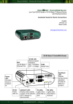
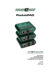

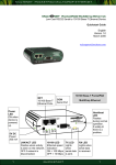



![600A01-manual-V1[1]](http://vs1.manualzilla.com/store/data/005768384_1-b36f8a87433f2b6e700f051b34ad2f22-150x150.png)