1
UM10237
NXP Semiconductors
Chapter 2: LPC2468 memory map
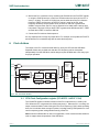
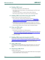
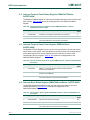
4. LPC2400 memory re-mapping and boot ROM
4.1 Memory map concepts and operating modes
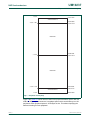
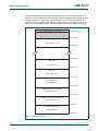
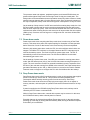
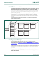
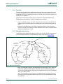
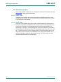
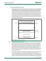
The basic concept on the LPC2400 is that each memory area has a "natural" location in
the memory map. This is the address range for which code residing in that area is written.
The bulk of each memory space remains permanently fixed in the same location,
eliminating the need to have portions of the code designed to run in different address
ranges.
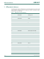
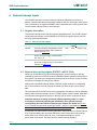
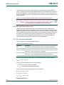
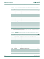
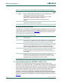
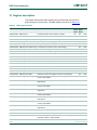
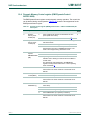
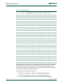
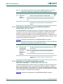
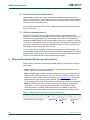
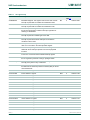
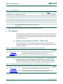
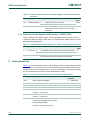
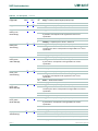
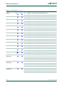
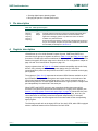
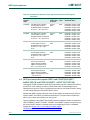
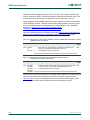
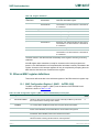
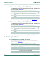
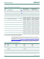
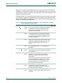
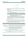
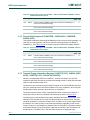
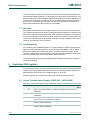
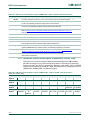
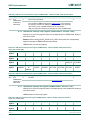
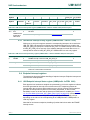
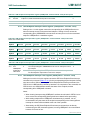
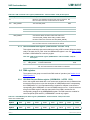
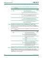
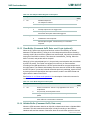
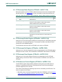
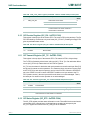
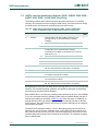
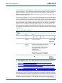
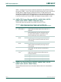
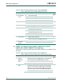
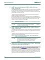
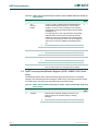
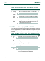
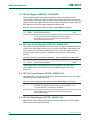
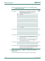
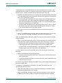
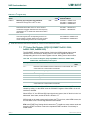
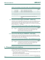
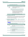
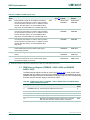
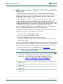
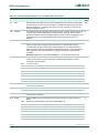
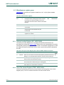
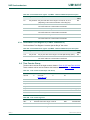
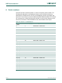
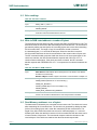
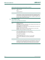
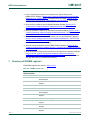
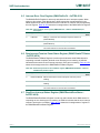
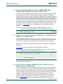
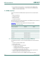
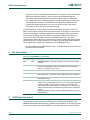
Because of the location of the interrupt vectors on the ARM7 processor (at addresses
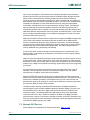
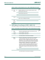
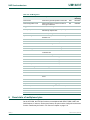
0x0000 0000 through 0x0000 001C, as shown in Table 2–5 below), a small portion of the
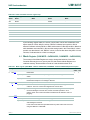
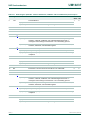
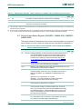
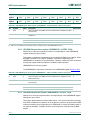
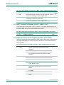
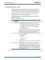
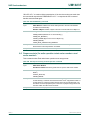
Boot ROM and SRAM spaces need to be re-mapped in order to allow alternative uses of
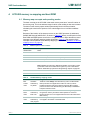
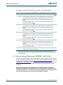
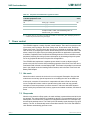
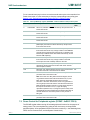
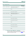
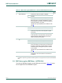
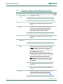
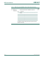
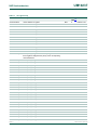
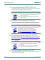
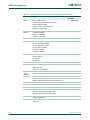
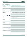
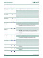
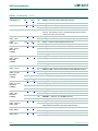
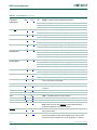
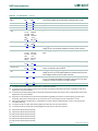
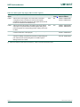
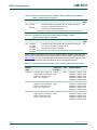
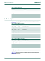
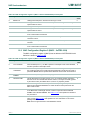
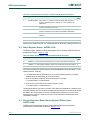
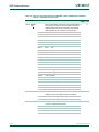
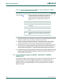
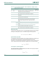
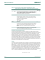
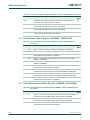
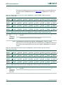
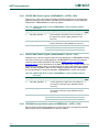
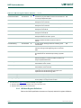
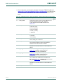
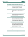
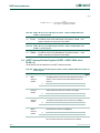
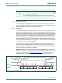
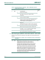
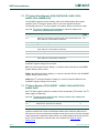
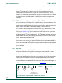
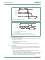
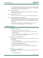
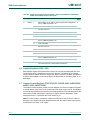
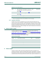
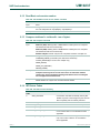
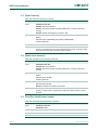
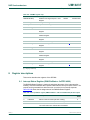
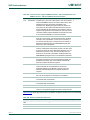
interrupts in the different operating modes described in Table 2–6. Re-mapping of the
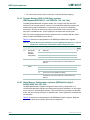
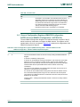
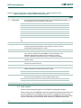
interrupts is accomplished via the Memory Mapping Control feature (Section 2–5 “Memory
mapping control” on page 15).
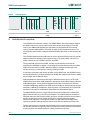
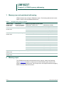
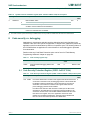
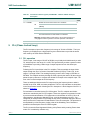
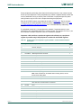
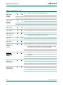
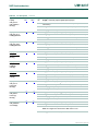
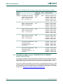
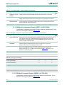
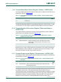
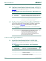
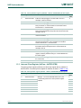
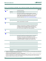
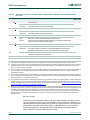
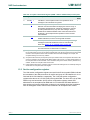
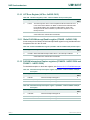
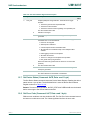
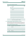
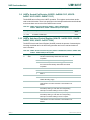
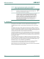
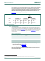
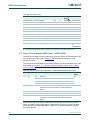
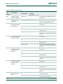
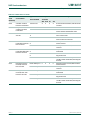
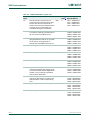
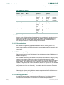
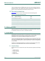
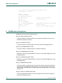
Table 5.
ARM exception vector locations
Address
Exception
0x0000 0000
Reset
0x0000 0004
Undefined Instruction
0x0000 0008
Software Interrupt
0x0000 000C
Prefetch Abort (instruction fetch memory fault)
0x0000 0010
Data Abort (data access memory fault)
0x0000 0014
Reserved
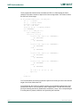
Note: Identified as reserved in ARM documentation, this location is used
by the Boot Loader as the Valid User Program key. This is described in
detail in "Flash Memory System and Programming" chapter on page 561.
0x0000 0018
IRQ
0x0000 001C
FIQ
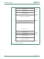
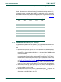
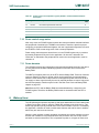
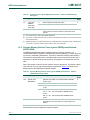
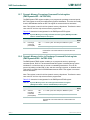
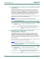
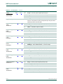
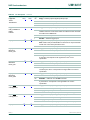
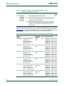
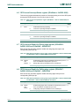
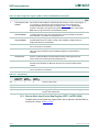
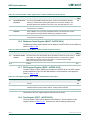
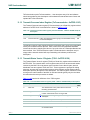
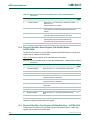
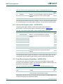
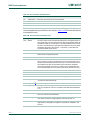
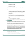
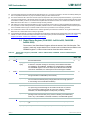
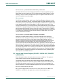
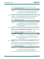
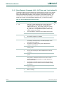
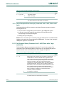
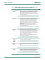
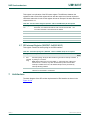
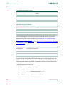
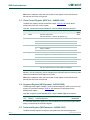
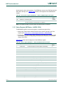
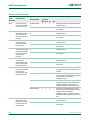
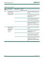
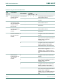
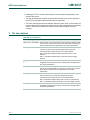
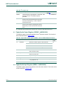
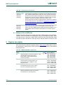
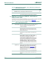
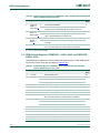
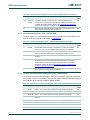
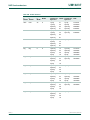
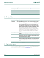
Table 6.
LPC2400 Memory mapping modes
Mode
Activation
Usage
Boot
Loader
mode
Hardware
activation by
any Reset
The Boot Loader always executes after any reset. The Boot ROM
interrupt vectors are mapped to the bottom of memory to allow
handling exceptions and using interrupts during the Boot Loading
process. A sector of the flash memory (the Boot flash) is available to
hold part of the Boot Code.
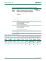
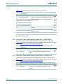
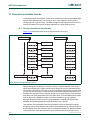
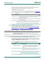
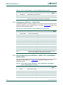
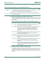
User
Flash
mode
Software
activation by
Boot code
Activated by the Boot Loader when a valid User Program Signature is
recognized in memory and Boot Loader operation is not forced.
Interrupt vectors are not re-mapped and are found in the bottom of the
flash memory.
User RAM Software
Activated by a User Program as desired. Interrupt vectors are
mode
activation by re-mapped to the bottom of the Static RAM.
User program
UM10237_1
User manual
© NXP B.V. 2006. All rights reserved.
Rev. 01 — 18 December 2006
14 of 664