1
UM10237
NXP Semiconductors
Chapter 23: LPC2468 Timer0/1/2/3
6. Example Timer Operation
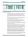
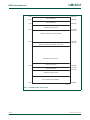
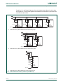
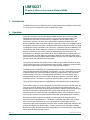
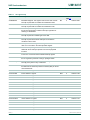
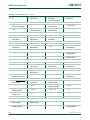
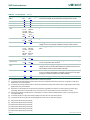
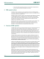
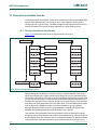
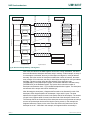
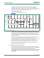
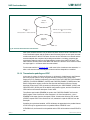
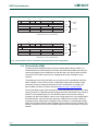
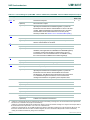
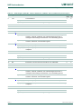
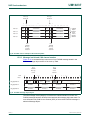
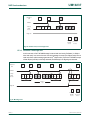
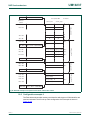
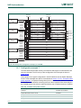
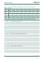
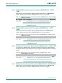
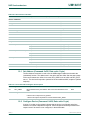
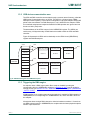
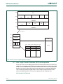
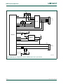
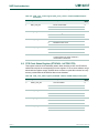
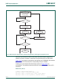
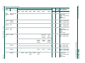
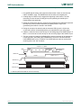
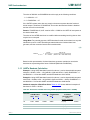
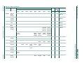
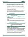
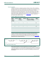
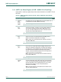
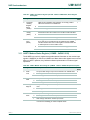
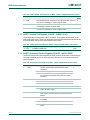
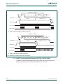
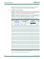
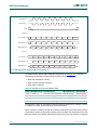
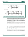
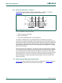
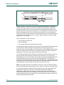
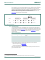
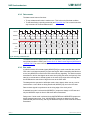
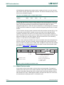
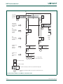
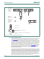
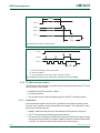
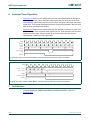
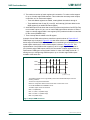
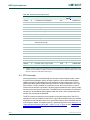
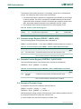
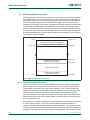
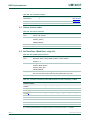
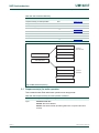
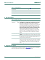
Figure 23–112 shows a timer configured to reset the count and generate an interrupt on
match. The prescaler is set to 2 and the match register set to 6. At the end of the timer
cycle where the match occurs, the timer count is reset. This gives a full length cycle to the
match value. The interrupt indicating that a match occurred is generated in the next clock
after the timer reached the match value.
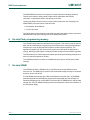
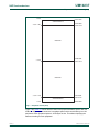
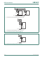
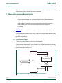
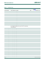
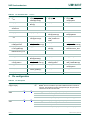
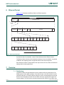
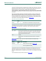
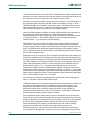
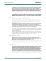
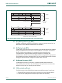
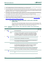
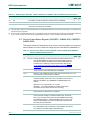
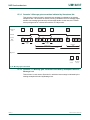
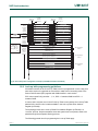
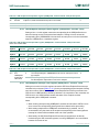
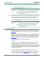
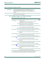
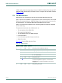
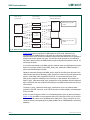
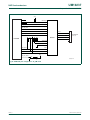
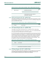
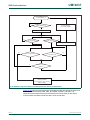
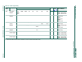
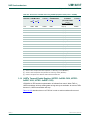
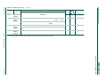
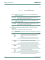
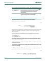
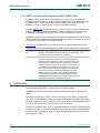
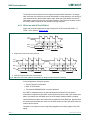
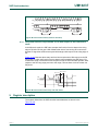
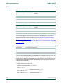
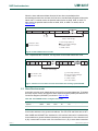
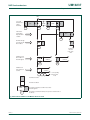
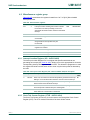
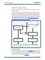
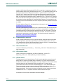
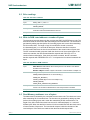
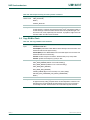
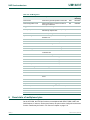
Figure 23–113 shows a timer configured to stop and generate an interrupt on match. The
prescaler is again set to 2 and the match register set to 6. In the next clock after the timer
reaches the match value, the timer enable bit in TCR is cleared, and the interrupt
indicating that a match occurred is generated.
PCLK
prescale
counter
2
timer
counter
4
0
1
2
0
1
5
2
6
0
1
0
2
0
1
1
timer counter
reset
interrupt
Fig 112.A timer cycle in which PR=2, MRx=6, and both interrupt and reset on match are enabled.
PCLK
prescale counter
timer counter
TCR[0]
(counter enable)
2
4
0
1
5
1
2
0
6
0
interrupt
Fig 113.A timer Cycle in Which PR=2, MRx=6, and both interrupt and stop on match are enabled
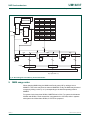
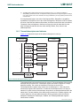
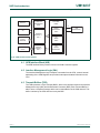
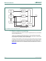
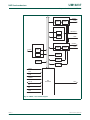
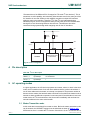
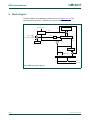
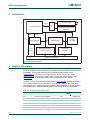
7. Architecture
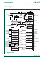
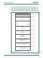
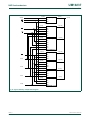
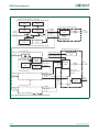
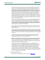
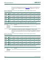
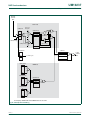
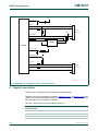
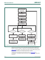
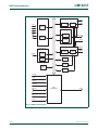
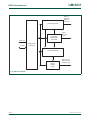
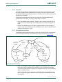
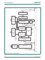
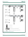
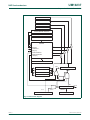
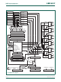
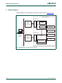
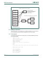
The block diagram for TIMER/COUNTER0 and TIMER/COUNTER1 is shown in
Figure 23–114.
UM10237_1
User manual
© NXP B.V. 2006. All rights reserved.
Rev. 01 — 18 December 2006
517 of 664