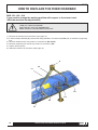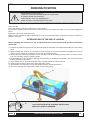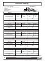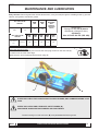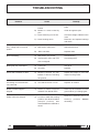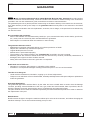
1
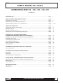
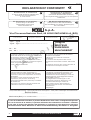
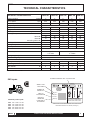
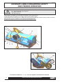
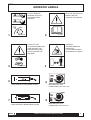
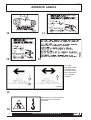
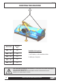
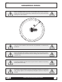
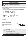
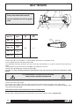
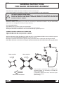
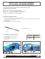
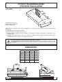
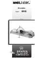
Shredder
type:
BNE
04.09.2009
04.09.2009
INTENDED USE
NOBILI S.p.A. - Agricultural Machinery Manufactures - wishes first of all to thank you for the wise choice you have
made in purchasing one of its machines, whilst assuring you that the maximum efforts have been put into making
the machine as advanced and practical as possible.
In order to get the best use out of the machine and prolong its working life, NOBILI S.p.A. has decided to give a
few practical hints to help you use it to its full potential and to help you avoid those problems that are due, in the
majority of cases, not to manufacturing defects, but mainly to negligence and carelessness.
NOBILI BNE multivalent shredders have been designed for the following activities: care of grassland and public
parks, shredding of thin wood, vine sarments, and potato leaves.
Machine tools - blades or rams - must NEVER touch the ground.
The correct use of the machine includes:
- following carefully manufacture's instructions regarding use, maintenance and care of your machine.
- using original spare parts only, as well as original or approved units and accessories.
The use of the machine, its maintenance and repairs are reserved to specialized people, who are familiar with the
technical data and features of these machines.
CORRECT USE OF THE MACHINE
WARNING: Before using the machine it is necessary to check the following points:
1°)
The machine should be included in the weight and overall dimension limits mentioned in the
tractor use manual, regarding the equipped tools
2°)
In case of rear coupling, with the machine raised from the ground, check that on the tractor front
axle (steering) there is a residual weight not lower than 20% of total weight.
EXAMPLE
Total weight = Tractor weight + Machine weight = 2500 Kg + 800 Kg = 3300 Kg
Residual weight on the steering axle = 20% di 3300 Kg = 660 Kg
IT IS NOT ALLOWED:
•
•
•
•
•
•
Working on stony or uneven grounds.
Transporting persons, animals, or things.
Towing cars or equipment.
Working near houses or roads.
Fitting other equipment which may change the machine's characteristics.
Machine tools must NEVER touch the ground.
WARNING! THIS SYMBOL, USED THROUGHOUT THIS MANUAL, MARKS
INSTRUCTIONS THAT MAY AFFECT YOUR SAFETY, OTHER PEOPLE'S SAFETY, AND
THE EFFICIENT WORKING OF THE MACHINE. ALWAYS FOLLOW THE SAFETY
INSTRUCTIONS SCRUPULOUSLY.
2
AGRICULTURAL MACHINERY MANUFACTURERS
04.09.2009
USER'S MANUAL No. AO 917
SHREDDERS: BNE 100 - 120 - 150 - 180 - 210
CONTENTS
INTENDED USE ....................................................................................................................... Page
2
MARKS AND MACHINE IDENTIFICATION ............................................................................ Page
Declaration of conformity .......................................................................................................... Page
Characteristics and machine identification ............................................................................... Page
Decals regarding: Safety- Use - Maintenance .......................................................................... Page
4
4
5
6-7-8
SAFETY PRECAUTIONS ......................................................................................................... Page
Hoisting the machine and transport .......................................................................................... Page
Dangerous areas ...................................................................................................................... Page
Recommandations for use ........................................................................................................ Page
Checking tools and corresponding locking pins ....................................................................... Page
9
10
11
12
13
STARTING AND STOPPING THE MACHINE
INFORMATION REGARDING USE AND ADJUSTMENT .......................................................... Page
Assembly of skids, roller, wheels and corresponding guards ................................................... Page
Coupling to the tractor .............................................................................................................. Page
Connecting the propeller shaft .................................................................................................. Page
Working height adjustment ....................................................................................................... Page
How to displace fixed drawbar .................................................................................................. Page
Parking position ........................................................................................................................ Page
14
14
15
16
17
18
19
INFORMATION REGARDING ACOUSTIC PRESSURE ......................................................... Page
Air noise emitted ....................................................................................................................... Page
20
20
INFORMATION REGARDING MAINTENANCE ...................................................................... Page
Lubrication ................................................................................................................................ Page
Belt tension ............................................................................................................................... Page
Tool replacement and balancing ............................................................................................... Page
21
21
22
23
ACCESSORIES: DRAWBARS WITH LATERAL SHIFTING ................................................... Page
Assembly and adjustments of drawbars with lateral shifting .................................................... Page
Warning signs ........................................................................................................................... Page
Overall dimensions ................................................................................................................... Page
24
24
25
25
TROUBLESHOOTING.............................................................................................................. Page
WARRANTY ............................................................................................................................. Page
26
27
AGRICULTURAL MACHINERY MANUFACTURERS
3
04.09.2009
DECLARATION OF CONFORMITY
Dichiarazione di Conformità
ai sensi della direttiva CEE 89/392
e successive modificazioni.
Il costruttore:
EC declaration of conformity
(conforming to directive
89/392/EEC amended)
The manufacturer:
Declaration de conformité
à la directive "machines"
(Directive 89/392/CEE modifiée)
et aux réglementations prises pour sa transposition
Le fabricant:
EG-Konformitätserklärung
(entsprechend der EG-Richtlinie
89/392/EWG und deren Änderungen).
Der Hersteller :
S.p.A.
Via Circonvallazione Sud, 46 40062 MOLINELLA (BO)
dichiara che la macchina
sotto descritta:
déclare que la machine
désignée ci-dessous:
declares that the product
descr ibed hereafter:
Tipo - Type
Type - Typ:......................................
N° - N°
No - Nr.: .......................................
S
-
è conforme ai Requisiti essenziali di Sicurezza e di
Tutela della Salute di cui alla Direttiva CEE 89/392 e
sue successive modificazioni, nonché ai Requisiti di
cui alle seguenti Direttive CEE: 86 /188 /CEE
Per la verifica della Conformità di cui alle Direttive
sopra menzionate, sono state consultate le seguenti:
Norme Armonizzate: EN 294 EN 349
Norme e specifiche Tecniche:
F
A
C
to which this declaration applies, confor ms to the
essential health and safety requirements of
European Council Directive 89/392 CEE amended
and conforms also to the requirements of Directive
86/188/EEC.
-to conform to these essential health and safety
requirements, the provisions of following
harmonized standards were par ticularly considered:
EN 294 EN 349
-the provision of following national standards and
specifications were also considered:
E
erklär t in alleiniger
Verantwor tung, daß das
Produkt:
L
I
TRINCIA
BROYEUR
SHREDDER
MULCHGERÄT
M
I
-est conforme aux dispositions de la directive
européenne 89/392/CEE
modifiée ainsi qu'à celles de la directive:
86/188/CEE.
-est conforme aux dispositions des normes
européennes harmonisées suivantes: EN 294 EN
349
-est égalment conforme aux normes nationales et
aux dispositions techniques suivantes:
auf das sich diese Erklärung bezieht, den
einschlägigen grundlegenden Scherheits- und
Gsundheitsanforderungen der EG-Richtlinie
89/392/EWG und deren Änderungen, sowie den
Anforderungen der einschlägigen EG-Richtlinie
86/188/EWG entspricht.
Zur sachgerechten Umsetzung der in den
EG-Richtlinien genannten Sicherheits- und
Gesundheitsanforderungen wurden die
harmonisierten Normen: EN 294 EN 349
sowie die nationalen Normen und techischen
Spezifikationen:
herangezogen.
Responsabile della Sicurezza -- Responsable Sécurité et Homologations -- Safety Officer--Beauftragter für Gerätesicherheit
Barilani Andrea
..............................................................
Molinella (BO) Li-Le-Date-Den:................
In caso di vendita della macchina, la presente dichiarazione deve essere consegnata all'acquirente.
En cas de revente de la machine, la présente déclaration de conformité est a remettre à l'acheteur.
In the case of resale of the machine, this declaration of conformity is to be passed on to the buyer.
Bei Weiterverkauf dieser Maschine ist diese Konformitätserklärung dem Käufer zu übergeben.
4
AGRICULTURAL MACHINERY MANUFACTURERS
04.09.2009
TECHNICAL CHARACTERISTICS
TECHNICAL CHARACTERISTICS
BNE 100
BNE 120
BNE 150
BNE 180
BNE 210
Tractor coupling
Range
1°
1°
1°
1°
1°
P.T.O. speed
Required power
r.p.m.
Kw
540
11
540
15
540
18
540
22
540
29
Transport position
Max. transport width
mm
1245
1445
Transversal
1730
2015
2300
Kg
180
--
190
--
210
370
240
370
270
370
Blades Y N°
Vanes N°
28
14
32
16
40
20
48
24
56
28
Rams N°
Swivelling blades N°
14
28
16
32
20
40
24
48
28
56
Weight for standard version
Working position central or on the right
Working components
Working width
Cutting rim speed
mm
m\sec
978*
48,5
1177*
48,5
1460*
47,9
1745*
47,9
2030*
47,9
Rotor speed
Main drive
r.p.m.
2230
2230
2207
Bevel Gear Pair
2207
2207
Secondary drive
Belt type: B 46
n° 3 belts
Cutting height adjustment
Lateral shifting adjustment
Belt type: SPBX
n° 3 belts
Manual
Manual or hydraulic
ACCESSORIES
Sliding drawbar, hydraulic
Parallelogram drawbar, hydraulic
Rear wheels
Rear roller
N°
No
No
No
No
Yes
Yes
Yes
Yes
Yes
Yes
2
Yes
2
Yes
2
Yes
2
Yes
2
Yes
* Dimension with rams 06
NOME ED INDIRIZZO DEL COSTRUTTORE
540 r.p.m.
BNE 1
COSTRUZIONI R
MECCANICHE
PER L’AGRICOLTURA
SERIE E TIPO
MACCHINA
NUMERO DI
MATRICOLA
ANNO DI
COSTRUZIONE
TRINCE
BROYEURS
TRITURATOR
MULCHER
BLASIA 460 SUPERTRACTOR
(ISO 460)
UNIVERSAL
MU / EP2
Mod. :
Num. :
Data :
Machine power input:
BNE
BNE
BNE
BNE
BNE
100
120
150
180
210
11 Kw
15 Kw
18 Kw
22 Kw
29 Kw
15
20
25
30
40
HP
HP
HP
HP
HP
MASSA IN
VERSIONE
COMPLETA DI
ACCESSORI
Massa Kg :
LUBRIFICANTI CONSIGLIATI
LUBRIC. ACONSEJADOS - RECOMMENDED LUBRICANTS
EMPFOHLENE OELE/FETTE - LUBRIFIANTS CONSEILLES
MARCATURA E RICONOSCIMENTO DELLA MACCHINA
TARGHETTA FISSATA AL TELAIO (Vedi Pag. 6)
AGRICULTURAL MACHINERY MANUFACTURERS
5
04.09.2009
ADHESIVE LABELS REGARDING SAFETY
AND PROPER OPERATION
A)
B)
CB)
CR)
Machine identification metal plate.
Type and model of the machine
White reflectors
Red reflectors
Safety labels are located on the machine according to the pictures below.
Decals have been designed for your safety and for other people's safety.
The machine's owner or the person in charge must be sure the operator has read the Instruction Manual carefully.
Keep decals in good conditions and replace the damaged ones.
A
B
8
1
12
CB
1
4
2
11
7
13
CB
10
4
CR
CR
5
The adhesive labels N° 6 - 7 - 12 - 14 are not applied on the BNE series machine.
6
AGRICULTURAL MACHINERY MANUFACTURERS
04.09.2009
ADHESIVE LABELS
DO NOT REMOVE
GUARDS UNTIL ALL
ROTATING PARTS
ARE IDLE
1
READ THE INSTRUCTION
MANUAL BEFORE
STARTING THE MACHINE
2
0018646
0018642
TURN OFF THE
TRACTOR ENGINE AND
TAKE THE KEY OFF
BEFORE SERVICING
OR ADJUSTING THE
MACHINE
3
DANGER!
THROWN OBJECTS.
STAND OFF.
DO NOT WORK NEAR
BUILDINGS OR ROADS
4
0018650
5
0018645
6
GREASE EVERY 4 WORKING HOURS
MACHINE SET FOR
POWER INPUT AT 1000 r.p.m.
50 h.
7
8
GREASE EVERY 50 WORKING HOURS
MACHINE SET FOR
POWER INPUT AT 540 r.p.m.
AGRICULTURAL MACHINERY MANUFACTURERS
7
04.09.2009
ADHESIVE LABELS
10
12
11
13
LIFT THE
MACHINE FROM
THE GROUND
BEFORE GOING
INTO REVERSE
OR TURNING
SHARPLY.
0018658
14
INDICATION OF THE HOOKING
POINTS FOR LIFTING THE
MACHINE.
15
8
AGRICULTURAL MACHINERY MANUFACTURERS
04.09.2009
SAFETY PRECAUTIONS
MANY INDUSTRIAL INJURIES ARE DUE TO THE LACK OF
RESPECT OF THE MOST ELEMENTARY SAFETY PRECAUTIONS.
•
Thus it is necessary that whoever needs to work or to carry out the maintenance of the machine,
knows the safety precautions described in the manual or on the decals.
•
Before any cleaning or maintenance operations, it is necessary to lay the machine horizontally on the
ground or on strong supports, stop the tractor engine and remove the propeller shaft.
•
Before beginning work, check: tightening of bolts, integrity and efficiency of guards, right position of
safety pins.
•
Be sure that the tractor meets the CHARACTERISTICS REQUIRED BY THE MACHINE USED.
•
Keep persons and animals away from the machine before its starting.
•
Do not leave the machine running without surveillance.
•
Do not wear clothes which can get entangled.
•
Do not transport persons or animals on the machines.
•
AND THAT, DURING ASSEMBLY, THE GUARDS
Check that the PROPELLER SHAFT IS MARKED
ARE PROTECTED AGAINST ROTATION with the appropriate chains.
•
Be particularly careful when you work on cat’s backs or ditches.
•
Be particularly careful when you work on cat’s backs or ditches.
The uneven ground can make the guards temporarily inefficient and allow the projection of stones or
fragments in a wide range (See page 11).
•
Be particularly prudent during the road-transport of the machine.
The user must be sure that the transport complies with the highway Code of the Country where it is
CARRIED OUT.
AGRICULTURAL MACHINERY MANUFACTURERS
9
04.09.2009
HOISTING THE MACHINE
MACHINE
WEIGHT
Kg
BNE 100
180
BNE 120
190
BNE 150
210
BNE 180
240
BNE 210
270
Available hitch points:
1) ø 20 holes, on the machine sides
2) hitch pin, 3rd point
USE HOISTING EQUIPMENT ACCORDING TO THE RULES IN FORCE AND RIGHT
FOR THE MACHINE WEIGHT.
WARNING: BE CAREFUL AS ACCESSORIES AFFECT MACHINE BALANCE.
NEVER LIFT UNBALANCED LOADS.
10
AGRICULTURAL MACHINERY MANUFACTURERS
04.09.2009
DANGEROUS AREAS
Before shredding: Keep all persons and animals away from the machine
danger zone. This zone is defined by a radius (R) of 50 m (164') around the
working line of the machine.
The use of the machine hood must be only destined to maintenance
operations.
Before maintaining the machine, stop the tractor motor, turn off the engine,
remove ignition key and wait until all moving parts have come to a
complete stop.
It is strictly forbidden to leave the hood open when the machine is operating
and its parts are moving.
The misuse of the machine may cause involuntary projection of stones and
other foreign objects, and consequently damages to persons, things and
animals.
AGRICULTURAL MACHINERY MANUFACTURERS
11
04.09.2009
RECOMMENDATIONS FOR USE
ALWAYS STOP THE TRACTOR ENGINE BEFORE CARRYING OUT ANY WORK OF
ADJUSTMENT OR CLEANING ON THE MACHINE.
BEFORE STARTING THE ADVANCING OF THE MACHINE, WAIT THAT THE ROTOR REACHES THE R.P.M.
WORK ONLY ON STRAIGHT LINE, LIFT THE MACHINE FROM THE GROUND BEFORE CHANGING
DIRECTION.
DO NOT ACTIVATE THE SIDE DISPLACEMENT WITHOUT LIFTING THE MACHINE.
IF DURING THE LIFTING FROM THE GROUND, THE JOINTS OF THE PROPELLER SHAFT ARE BENT TO
MORE THAN 40° (STILL P.T.O.) REMOVE THE SHAFT OF THE TRACTOR P.T.O.
DURING WORK, BLADES OR RAMS SHOULD NOT TOUCH THE GROUND.
DAILY CHECK THE WEAR OF BLADES OR RAMS.
IN CASE OF IRREGULAR CONSUMPTIONS OR BREAKS, IMMEDIATELY SUBSTITUTE THE DAMAGED
PARTS. USE ONLY ORIGINAL SPARE PARTS.
AFTER THE FIRST HOURS OF WORK (3 HOURS) CHECK THE TENSION OF THE BELTS, DAILY CONTROL
THE TIGHTENING OF ALL NUTS AND BOLTS AND THE TENSION OF THE BELTS.
VERIFY SPECIALLY THE TIGHTENING OF BLADE BOLTS (See page 13).
CHECK THAT THE SAFETY CHAINS OF PINS AND THE ANTIROTATION CHAINS OF THE PROPELLER
SHAFT GUARDS ARE INTACT AND COUPLED UP.
CLEAN, WASH, GREASE THE INSIDE AND OUTSIDE OF THE MACHINE AT REGULAR INTERVALS.
SPECIALLY REMOVE THE MATERIAL SETTLED ON THE ROTOR AND BLADE SUPPORTS.
BEFORE A LONG PERIOD OF INACTIVITY THE MACHINE SHOULD BE CLEANED AND GREASED. PUT
IN A PLACE PROTECTED FROM BAD WEATHER.
THE USER IS COMPLETELY RESPONSIBLE OF ROAD-TRANSPORT. HE MUST CHECK THE COMPLIANCE
WITH THE HIGHWAY CODE IN FORCE IN HIS COUNTRY.
IF A TRACTOR WITHOUT SOUNDPROOF AND PRESSURIZED CABIN IS USED, IT IS NECESSARY THAT
THE OPERATOR USES INDIVIDUAL PROTECTION SYSTEMS:
1)
PROTECTION EARPIECES FOR NOISE, IF STANDARD EXPOSURE LEVELS ARE
EXCEEDED.
2)
DUST MASK, IF A GREAT QUANTITY OF DUST IS RAISED BECAUSE OF EITHER THE
KIND OF PRODUCT WORKED OR VERY DRY GROUND OR USE OF OPEN MACHINE.
IF DURING WORK YOU NOTICE UNUSUAL VIBRATIONS OF THE MACHINE, STOP IMMEDIATELY AND
CHECK THE INTEGRITY OF ROTOR AND BLADES OR RAMS.
EXCESSIVE VIBRATIONS CAN CAUSE PHYSICAL DAMAGES TO THE DRIVER.
THE MANUFACTURER DISCLAIMS ALL RESPONSIBILITY IN CASE OF DAMAGES OR ACCIDENTS
CAUSED BY AN INAPPROPRIATE USE OR NON-OBSERVANCE OF RECOMMENDATIONS INCLUDED IN
THE USE AND MAINTENANCE MANUAL.
12
AGRICULTURAL MACHINERY MANUFACTURERS
04.09.2009
CHECK BLADES OR RAMS AND THEIR
FASTENING ELEMENTS
Blades or rams: to be checked always before using the machine
to be checked immediately after an obstacle
Shredding quality, machine integrity and safety depend on the care which will be devoted to these elements.
They must be replaced immediately if damaged.
Normal wear (specially rapid on sandy grounds or working with the machine too low) and bumps against obstacles
can cause distortions or cracks in the blades or rams, which can lead to:
• Worsening in the work quality,
• Increase in vibrations and consequent mechanical damages in the machine,
• Total or partial break of the blades and rams with consequent projection of fragments at high speed.
L
L
MACHINE
BNE VK VKD VKE
WMU VKR
BNU BNG NK
INITIAL DIAMETER OF
THE HOLE
0.63"
1"
MAXIMUM DIAMETER
ADMITTED
0.71"
1.07"
INITIAL LENGTH OF
BLADE OR HAMMER
4.33"
7.09"
MINIMUM LENGTH
ACCEPTABLE
3.54"
5.92"
F
F
BNE 4
F
F
L
L
Worn blades or rams:
The hole (F) of the pin should not be ovalized over 2mm from the
original diameter.
The length (L) of the blade or ram should not be reduced over 20
mm.
The pin fixing can be carried out with split pins or nuts,
according to the model of the machine.
H
S
Pins should be replaced if:
They are clearly bent or damaged in the thread: in particular check
(if welded) the welding integrity of the plate (S).
The tracking made by the wear of the blade or ram (H) is greater of
2 mm.
BNE 5
During assembly:
The selflocking split pins or nuts should be changed every time.
Torque wrench setting for M16 nut: 100 Nm
Torque wrench setting for M20 nut: 250 Nm
Check that the pin with tooth or the pin with hexagonal head, CANNOT rotate in their seat on
the support, because this could cause an abnormal consumption.
AGRICULTURAL MACHINERY MANUFACTURERS
13
04.09.2009
INSTRUCTIONS
FOR SKIDS, ROLLER, WHEELS ASSEMBLY
Whenever the machine is delivered with skids, roller and wheels not mounted because of shipping
requirements.
In order to use the machine with roller or wheels, mount side guards (SL),
according to
rules.
Skids assembly:
Make use of holes (A) on the lateral sides.
On the skids, select the proper holes so as to get up
the machine from the ground, at the height required.
See page 17.
Mount the safety bar (B) on the rear side.
Roller assembly:
Make use of the pair of holes (V) on the lateral sides.
On the roller support, select the proper holes so as
to get up the machine from the ground, at the height
required. See page 17.
Mount guards (SL) on the lateral sides.
Wheel unit assembly:
Make use of the pair of holes (V) on the lateral sides.
On the wheel support, select the proper holes so as
to get up the machine from the ground, at the height
required. See page 17.
Mount guards (SL) on the lateral sides.
Mount the safety bar (B) on the rear side.
A
B
SL
V
A
Wheels herein described are
mounted laterally and are not
steering: therefore, track can not be
controlled.
In order to use the machine with skids or wheels, mount the bar (B) which determines
the rear safety distance required by
rules.
Before connecting the machine to the tractor, make sure the transmission unit
is equipped with oil drain plug (T).
For shipping requirements the machine may be shipped in vertical position; in
such a case, a blind plug is fitted on the transmission unit
so as to avoid oil overflow.
Therefore, replace the fitted plug with the drain plug contained in the proper
packing joined to the machine.
14
AGRICULTURAL MACHINERY MANUFACTURERS
T
BNE 6
04.09.2009
COUPLING TO THE TRACTOR
THE MACHINE HAS BEEN DESIGNED FOR COUPLING TO THE TRACTOR PROVIDED
WITH REAR ELEVATOR.
WARNING: IN THE THREE-POINT HITCH AREA YOU MAY RUN THE RISK OF HARMING
YOURSELF.
WARNING: GET OUT OF THE THREE-POINT HITCH AREA WHILE THE ELEVATOR IS
RUNNING!
Machines type BNE 150 - 180 - 210 are provided
with two different hitch positions; select between
the central position and the lateral one.
See page 18.
Before coupling the machine to the tractor, make
sure the drawbar is in the required position.
Check the elevator links are at the same height
from the ground, and fit them into the connecting
pins (D).
Fit safety pins (S).
Connect the 3rd point tie rod (P) to the connecting
rod (B) by the proper pin; adjust the length of the
3rd point tie rod so as to make the connecting rod
(B) reach a 45° angle when the machine is in the
working position.
S
D
If you run the machine without
connecting rod, or with connecting rod
blocked, the warranty will be voided,
as the roller or wheel supports could
have been damaged irreparably by
such operations.
P
B
45°
BNE 7
Get up the machine from the ground and adjust cutting height (please see: working height adjustment on
page 17).
Raise foot and secure it.
Adjust machine and elevator attitude by placing the machine horizontally or slightly higher on the rear side so as
to make material infeed easier.
S
S
BNE
8
SECURE ALL PINS WITH SAFETY PINS
REPLACE LOCKS IF DAMAGED
AGRICULTURAL MACHINERY MANUFACTURERS
BNE
9
15
04.09.2009
CONNECTING THE PROPELLER SHAFT
THE TRACTOR ENGINE SHOULD NOT RUN, THE MACHINE SHOULD BE CORRECTLY
CONNECTED TO THE TRACTOR (See page 15).
IT IS FUNDAMENTAL TO HAVE A PROPELLER SHAFT OF APPROPRIATE LENGTH.
Measure the minimum distance (A) between
the notch of the tractor P.T.O. and that of the
shredder, when they are on the same axis.
TP
A
BNE 10
Measure the distance of the propeller shaft, in the position of minimum
extension (all closed).
The measure B should be smaller than A of at least 25 mm.
During work both inside that outside plastic pipes should not bump
against heads.
If the propeller shaft is too long, before cutting metal pipes and guards,
it is necessary to check that, when it is in the maximum extension position,
inside metal pipes remain overlapped at least of 1/3 of the length (L).
B = A- 25 mm
BNE 11
25 mm
If the overlapping is smaller, there is too much difference between
the minimum and maximum position of the transmission.
If this occurs, it is necessary to ask for longer lower connecting
arm to space more the machine from the tractor.
1/3
L
Be careful to cut surface: trim the cut inside and outside, clean for
eliminating chips and dirt, and grease with lithium grease.
BNE
12
L
Always check that the shaft is dimensioned according to the power of
the machine declared.
Check that the propeller shaft does not take angles over the value
admitted.
MAX 20°
Check that the machine cannot be raised over the maximum dimension
allowed by the shaft length: it could come out.
If the machine is connected to a tractor provided with
tracks or without double clutch, a cardan shaft with freewheel should be used to avoid the inertia of the shredder
rotor stopping quickly the tractor-machine unit.
BNE 13
MAXIMUM 20° - running
MAXIMUM 40° - still
BLOCK THE ROTATION OF THE CARDAN JOINT PROTECTION WITH THE APPROPRIATE
CHAINS.
16
AGRICULTURAL MACHINERY MANUFACTURERS
04.09.2009
WORKING HEIGHT ADJUSTMENT
BLADES MUST NEVER TOUCH THE GROUND!
LEAVE AT LEAST 40 MM.
B
VERSION WITH SKIDS:
RAISE THE MACHINE SLIGHTLY FROM THE GROUND
Remove bolts (A, B, C) which secure skid (SL), to the
machine and to guard (P).
On the skid (SL) select holes according to the height
required, fit bolts (A and B) and screw them.
Fit bolt (C) into the guard hole (P), keeping the guard parallel
to the lower edge of the side part.
Screw and tighten all bolts.
C
BNE
14
A
P
SL
VERSION WITH ROLLER:
RAISE THE MACHINE SLIGHTLY FROM THE GROUND
Loosen bolts (OS) on one side, unscrew and remove bolts
(OD) on the other side.
On the support select the holes right for the height desired,
then fit bolts (OD) and screw nuts but do not tighten them.
Remove bolts (OS) and fit them into the holes corresponding
to those selected on the other side.
Screw and tighten all bolts.
OD
VERSION WITH WHEELS:
RAISE THE MACHINE SLIGHTLY FROM THE GROUND
Loosen bolts (OS) and on the support select the holes right
for the height desired, then fit and tighten bolts (OS).
PERFORM THE SAME OPERATION AT THE OTHER.
OD
AGRICULTURAL MACHINERY MANUFACTURERS
17
04.09.2009
HOW TO DISPLACE THE FIXED DRAWBAR
BNE 150 - 180 - 210
If you need to change the working position with respect to the tractor track.
(With the machine already attached)
DISCONNECT TRACTOR P.T.O.
TURN OFF TRACTOR ENGINE.
TAKE THE KEY OFF THE DASHBOARD.
MAKE SURE ALL MOVING PARTS ARE IDLE.
1 ) Remove the machine from the tractor (See page 15).
2 ) In order to adjust drawbar (A), remove bolts fixing drawbar to connections (P1, P3, F1), as well as the supporting
foot.
3 ) Remove drawbar and fit it by means of connections (P2, P4, F2).
4 ) Remove supporting foot and fit it by means of connection (P3).
5 ) Tighten bolts properly.
6 ) Attach the machine to the tractor (See page 15).
A
F2
F1
P4
P3
P2
P1
18
AGRICULTURAL MACHINERY MANUFACTURERS
04.09.2009
PARKING POSITION
DISCONNECT TRACTOR P.T.O.
TURN OFF TRACTOR ENGINE WHEN THE MACHINE
IS RAISED FROM THE GROUND.
TAKE THE KEY OFF THE DASHBOARD.
MAKE SURE ALL MOVING PARTS ARE IDLE.
CHOOSE A STABLE, FLAT GROUND TO PERFORM THE FOLLOWING OPERATIONS
Lower foot (P).
Lower the elevator until the machine rests on the ground.
Disconnect propeller shaft from tractor P.T.O. and secure it to the suitable hook (G), so as to avoid damaging the
guard.
Extract pins and move away the tractor.
Make sure the machine is slightly tilted forward so as to prevent backwater on flat parts when the machine is
parked in the open.
INTERVENTIONS AT THE END OF SEASON
Before garaging the machine in a dry and protected place, some maintenance operations should be
carried out:
1) Remove the Cardan shaft and carry out the maintenance separately (see Instruction handbook of the Cardan
joint).
2) Wash carefully the machine, in particular inner parts, being sure to have removed completely every rests of
earth or grass. Check the protections of the rotor and roller bearings.
3) Grease the rotor bearings, rotating the rotor manually, until the exceeding grease comes out from the inner
part of the bearing supports cleaning inside.
4) Disassemble the roller supports, cleaning and greasing the bearings and spacers and checking that the
bearing protections are intact.
5) Put a grease film on all parts where the paint or galvanization has been removed.
6) Remove the protection guard of the belts and clean inside.
7) Disassemble and check the knives and blades and their fastening elements.
8) Check the integrity of the protection straps and pin safety laces.
G
P
S
BNE
8
LOCK THE PIN WITH THE SUITABLE SAFETY PINS
REPLACE LOCKS IF DAMAGED.
AGRICULTURAL MACHINERY MANUFACTURERS
19
04.09.2009
AIR NOISE EMITTED
TRACTOR 60 CV
AIR NOISE EMITTED
Data taken according to the following rules:
UNI 7712
AFNOR S 31-069
NF S 31-027
BNE 15
MACHINE:
BNE 100
TRACTOR ONLY
Tractor cab
Level of acoustic pressure:
operator place dB(A)
OPEN
80.7
Level of acoustic power:
dB(A)
MACHINE:
CLOSED
78.8
TRACTOR+ MACHINE
OPEN
CLOSED
84.3
79.1
108.4
107.1
BNE 120
TRACTOR ONLY
Tractor cab
OPEN
Level of acoustic pressure:
operator place dB(A)
80.7
Level of acoustic power:
dB(A)
CLOSED
78.8
TRACTOR+ MACHINE
OPEN
CLOSED
84.3
79.1
108.4
107.1
MACHINE: BNE 150
TRACTOR ONLY
Tractor cab
OPEN
Level of acoustic pressure:
operator place dB(A)
80.7
Level of acoustic power:
dB(A)
CLOSED
78.8
TRACTOR+ MACHINE
OPEN
CLOSED
84.3
79.1
108.4
107.1
MACHINE: BNE 180
TRACTOR ONLY
Tractor cab
Level of acoustic pressure:
operator place dB(A)
OPEN
CLOSED
80.7
Level of acoustic power:
dB(A)
78.8
TRACTOR+ MACHINE
OPEN
CLOSED
84.3
79.1
108.4
107.1
MACHINE: BNE 210
TRACTOR ONLY
Tractor cab
Level of acoustic pressure:
operator place dB(A)
Level of acoustic power:
dB(A)
TRACTOR+ MACHINE
OPEN
CLOSED
OPEN
CLOSED
80.7
78.8
84.3
79.1
107.1
108.4
When determining the noise value within the limit of 85 dB, take into consideration the acoustic pressure level.
20
AGRICULTURAL MACHINERY MANUFACTURERS
04.09.2009
MAINTENANCE AND LUBRICATION
Every 8 hours clean and grease the cardan transmission, cross journals (through the suitable greasers), grooved
sleeves, and guards, with lithium grease.
Olio
Oil SAE
SAE 140
90 EEP
P
IISO
SO 460
460
Transmission
unit
Quantity
Lt:
Olio
Oil SAE
SAE 140
90 EEP
P
IISO
SO 460
460
Transmission
unit
Quantity Lt:
BNE
180
BNE
210
1.5
1.5
MACHINES
WITH
CENTRAL
COUPLING
(AXIAL)
BNE
100
BNE
120
BNE
150
BNE
180
BNE
210
1.2
1.2
1.2
1.2
1.2
GEAR UNIT
Change oil after 30-40 hours.
Afterwards, change oil every
250 hours.
Use oil SAE 140 EP (ISO 460).
Every day check oil level.
Rest the machine horizontally and unscrew the main plug located on the rear side (L):
oil shall touch the lower hole edge.
Make sure the unit is equipped with air drain plug (T).
L
B
T
BNE 16
R
EVERY DAY CHECK THE CONDITION OF BLADES OR RAMS, AND CORRESPONDING LOCK
PINS.
EVERY DAY CLEAN AND LUBRICATE SAFETY VANES (B).
MAKE SURE VANES ARE NOT WARPED AND RUN FREELY.
Grease bearings on roller and rotor (R) every 4 hours with lithium grease.
AGRICULTURAL MACHINERY MANUFACTURERS
21
04.09.2009
BELT TENSION
H
PR
E
D
Every day check belt tension.
See the suitable slot on the guard
side.
BNE 17
A
Machine
Belts
BNE 100
B 46
BNE 120
B 46
BNE 150
SPBX
1250
BNE 180
SPBX
1250
BNE 210
SPBX
1250
P
B
(N)
(mm)
G
B
(P) Power
(B) Belt bending
25
6
Loosen bolts (A, no. 4) and (B, no. 1) which fasten transmission to shredder frame.
Loosen adjusting screw counternuts (H and D).
Turn adjusting screw (E) clockwise, and turn screw (G), anticlockwise, up to get the tension desired (See the
table).
That operation allows transmission axis (PR) to be parallel to rotor axis.
Tighten bolts (A and B) and counternuts (D and H).
In order to check parallelism between transmission axis and rotor axis, follow the indications listed
below:
IF THE MACHINE IS COUPLED TO THE TRACTOR,
REMOVE THE CARDAN TRANSMISSION
Dismount the belt safety guard.
Put a scale on the edges of the rotor pulley and rotate it until it touches the edges of the other pulley.
Both pulley edges shall touch the scale; otherwise, screw or unscrew adjusting screw (G) accordingly, after
loosening screws (A and B).
Belt tension must be restored within the first 3 working hours.
Afterwards, check belt tension periodically.
If rotor rotation speed decreases and belt tension can not be restored correctly, change belts.
22
AGRICULTURAL MACHINERY MANUFACTURERS
04.09.2009
GENERAL INSTRUCTIONS
FOR BLADE OR RAM REPLACEMENT
Daily check the condition and wear of blades and rams and their pins.
If you notice irregular consumptions or breaks, carry out immediately the part replacement.
USE ONLY ORIGINAL SPARE PARTS.
BEFORE CARRYING OUT REPLACEMENT, IT IS NECESSARY TO REMOVE THE MACHINE
FROM THE TRACTOR AND BEND IT FORWARD, MAKING IT LAYING ON COUPLING FOR
MODELS WITHOUT BONNET.
For partial replacement:
Besides the blade or ram pair worn or broken, it is necessary to substitute the blade or ram pair diametrically
opposed for not changing the already existing balancing.
For total replacement:
Small differences in weight of parts are unavoidable.
Weigh the single blade or ram blocks, chosing pairs of the same weight.
These pairs should be assembled on the rotor in diametrically opposed positions.
CHANGE THE SELFLOCKING NUTS EVERY TIME
Tighten the M16 nuts with a torque wrench of 100 Nm.
Tighten the M20 nuts with a torque wrench of 250 Nm.
After the adjustment check that there is a small end play (1-2 mm) between blades or rams and their supports.
After the repair, for checking the balancing, connect the tractor.
Keeping the machine raised from the ground, slowly increase the P.T.O. speed until reaching the R.P.M.
If the repair has been carried out correctly the machine should rotate at a R.P.M. without strong vibrations.
Rotor rotation
Rotor rotation
BNE 19
BNE 18
Direction of movement
If the machine assembles the Y blades with
ventilation blades, it is necessary to include also
them in the weighing.
If ventilation blades are used, check the right
direction of assembly.
(See drawing).
AGRICULTURAL MACHINERY MANUFACTURERS
23
04.09.2009
HOW TO SHIFT THE SLIDING DRAWBAR
OR THE PARALLELOGRAM DRAWBAR
If you need to change the working position with respect to the tractor track.
(With the machine already attached).
BNE 150 - 180 - 210 Version: axial movable coupling
BNE 150 - 180 - 210 Version: parallelogram movable coupling
Both types of couplings require the same operations.
ADJUSTMENT WITH MANUAL DRIVE:
1 ) Disconnect the machine from the tractor (See page 15).
2 ) In order to adjust the position of drawbar (A), remove the peg and extract rod (AS) from pin (P) joined to the
drawbar; and fit the rod in the pin.
3 ) Fit the safety pin.
4 ) Attach the machine to the tractor (See page 15).
BNE
20
Manual adjusting rod
AS
ADJUSTMENT WITH HYDRAULIC DRIVE:
1)
2)
3)
4)
Raise up the machine from the ground.
Select shifting.
Lay the machine onto the ground.
Start working.
MAX.
PRESSURE
AGIP
SUPERTRACTOR
UNIVERSAL
SAE 15W \ 40
120 BARS
A
A
P
24
OIL FOR
FILLING UP
P
AGRICULTURAL MACHINERY MANUFACTURERS
04.09.2009
FITTING THE WARNING SIGNS
FOR ROAD CIRCULATION
Series BNE
EXAMPLE of application of
reflector panels approved
by the highway code.
BN
E
21
BNE machines coupled to the tractor, are allowed to circulate on public road by observing the following
precautions:
1) The drawbar must be placed centrally.
2) Elevator side tie rods must be tensioned.
3) Approved reflector panels must be installed on the machine by means of brackets to be placed on the
machine sides.
4) Regarding the number and position of the panels it is NOT possible to give general information. They
should be defined according to the single characteristics.
IN CASE OF ROAD HAULAGE OF THE MACHINE YOU MUST:
FIT THE WARNING SIGNS REQUIRED AND APPROVED BY THE HIGHWAY CODE OF YOUR
COUNTRY.
DIMENSIONS
MACHINE
L
mm
H
mm
H1
mm
BNE 100
1230
860
1070
BNE 120
1430
860
1070
BNE 150
1720
860
1070
BNE 180
2000
860
1070
BNE 210
2280
860
1070
BNE 22
BN
E
23
H
L
H1
AGRICULTURAL MACHINERY MANUFACTURERS
25
04.09.2009
TROUBLESHOOTING
Cause
Remedy
A) Blades or rams worn or
broken.
Replace worn-out or broken
parts.
B) Blades or rams locked by
pins.
Clean and grease pins.
C) Rotor balancing not correct.
Check the weight of blade or ram
units.
D) Rotor bearings worn.
Dismount and replace bearings
and seals.
A) Belt tension really poor.
Adjust belt tension.
B)
Replace belts.
Problem
Excessive vibrations.
Poor cutting due to rotor low
speed.
Belt overheating.
Bevel gear pair overheated.
Quick wear of blades or rams.
Worn-out belts.
A) Belt tension not correct.
Check tension.
B) Transmission axis and rotor
axis not aligned.
Check alignment.
A) Lack of oil
Top up oil.
B) Oil spent.
Replace.
A) Working position too low,
blades or rams are touching
Adjust the height of rotor with
respect to the ground.
the ground.
Oil leaking from transmission
unit, belt side.
A) Oil retainer broken or worn.
Replace oil retainer.
Roller or wheel supports
A) Roller or wheel suppor ts
Raise up the machine from the
warped.
Safety vanes are warped.
suffered from lateral strain.
A) In order to reach the working
position, the raised machine
(traspor t position), was
lowered onto the material to
ground when you change gear.
Make the machine get to its
working
position
before
shredding.
shred.
26
AGRICULTURAL MACHINERY MANUFACTURERS
04.09.2009
GUARANTEE
S.p.A. Via Circonvallazione Sud 46, 40062 Molinella (Bologna) Italy, warrants this product against
defects in materials and workmanship, under the condition the machine is used according to the instructions
provided in the use and maintenance guide, and with the restrictions mentioned below.
The guarantee period is 12 (twelve) months commencing on the date of delivery of the machine to the customer;
such date shall be proved by the stamp on the guarantee card correctly filled in and returned to the Nobili
offices.
The guarantee is restricted to the sole replacement, ex-works, free of charge, of the parts held to be defective by
our Service Centre.
Not covered by this guarantee:
- Parts of the machine not manufactured by Nobili (ex.: tyres, transmission belts, cardan shafts, gear boxes,
etc.); such parts are covered by their own Manufacturer's guarantee.
- Parts subject to normal wear when the machine is used correctly.
The guarantee becomes void if:
- Modifications have been performed without prior written permission of Nobili.
- Repairs are undertaken by unauthorized persons.
- Original Nobili parts are not used.
- Maintenance is performed improperly.
- The machine is not used according to the "Intended Use" specified in the user's manual.
- Machine guards are removed. Guards shall never be removed: they shall be periodically checked and, if
damaged, their original condition shall be restored.
- Safety instructions listed in the user's guide are not respected.
Nobili shall not be liable for:
- Damages in connection with transport or unloading of the machine.
- Incidental or consequential damages resulting from broken parts or non-use of the machine.
The User is in charge of:
- Usual machine maintenance, lubrication, topping up of oil level, adjustments.
- Transport costs and labour costs for disassemble, assembly and adjustment of the parts subject to replacement
under the guarantee.
Guarantee Application:
The guarantee application shall be filled in by the seller and sent to Nobili within 4 weeks since the damage
occurred, providing: name and address of the user, type, model and serial number, date of purchase, date on
which the damage occurred, actual working hours, circumstances and supposed causes.
The parts shall be sent to Nobili and shall be inspected by the Nobili Technical Department in order to authorise
the replacement of the part.
Modifications:
Nobili reserves the right to change the machines without prior notice to the customers, and without changing the
machines already in use or the machines already put up for sale.
AGRICULTURAL MACHINERY MANUFACTURERS
27
RAPPRESENTATO DA:
REPRESENTED BY:
REPRESENTE PAR:
VERTRETEN DURCH:
40062 MOLINELLA (BO) ITALY - Via Circonvallazione Sud, 46
TEL. 051/88.14.44-45 TELEFAX 051 / 88.27.03