1
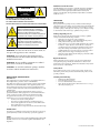
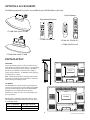
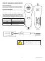
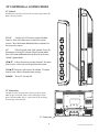
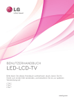
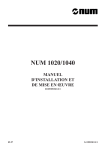
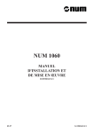
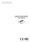
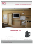
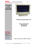
PDI Communication Systems 26” and 32” Healthcare LCD TV User Manual Models PDI-CV2600 PDI-CV3200 1 Document Number: Number: PD196-167R2 PD196-167R2 Document Healthcare Grade Television The PDI Healthcare series television is specifically designed for installation and use in a healthcare environment. The TV’s special design and safety features have been investigated by the Underwriters Laboratory and Listed for use in Hospitals, Nursing Facilities, Dialysis Clinics, and similar healthcare services. CAUTION RISK OF ELECTRIC SHOCK DO NOT OPEN ! CAUTION: TO REDUCE THE RISK OF ELECTRIC SHOCK DO NOT REMOVE COVER (OR BACK) NO USER SERVICEABLE PARTS INSIDE REFER SERVICING TO QUALIFIED SERVICE PERSONNEL SERVICING User Servicing If your product is not operating correctly or exhibits a marked change in performance and you are unable to restore normal operation by following the detailed procedure in its operating instructions, do not attempt to service it yourself as opening or removing covers may expose you to dangerous voltage or other hazards. Refer all servicing to qualified service personnel. This lightning flash with arrowhead symbol within an equilateral triangle is intended to alert the user to the presence of uninsulated dangerous voltage within the product’s enclosure that may be of sufficient magnitude to constitute a risk of electric shock to persons. Damage Requiring Service Unplug this product from the wall outlet and refer servicing to qualified service personnel under the following conditions: • When the power supply cord or plug is damaged. • If liquid has been spilled, or objects have fallen into the product. • If the product has been exposed to rain or water. • If the product does not operate normally by following the operating instructions. Adjust only those controls that are covered by the operating instructions as an improper adjustment of other controls may result in damage and will often require extensive work by a qualified technician to restore the product to its normal operation. • If the product has been dropped or damaged in any way. • When the product exhibits a distinct change in performance which indicates a need for service. The exclamation point within an equilateral triangle is intended to alert the user to the presence of important operating and maintenance (servicing) instructions in the literature accompanying the product. WARNING: To reduce the risk of fire or electric shock, do not expose this apparatus to rain or moisture. WARNING: To prevent injury, this apparatus must be securely attached to the floor/wall in accordance with the installation instructions. Replacement Parts WARNING: Do not install this equipment in a confined space such as a bookcase or similar unit. When replacement parts are required, be sure the service technician has used replacement parts specified by the manufacturer or have the same characteristics as the original part. Unauthorized substitutions may result in fire, electric shock, or other hazards. CAUTION: Do not block ventilation openings. Install in accordance with the manufacturer’s instructions. Safety Check REGULATORY INFORMATION FCC Part 15 Cleaning & Disinfecting Upon completion of any service or repairs to this product, ask the service technician to perform safety checks to determine that the product is in safe operating conditions. • • • • This equipment has been tested and found to comply with the limits for a Class B digital device, pursuant to Part 15 of the FCC Rules. These limits are designed to provide reasonable protection against harmful interference in a residential installation. This equipment generates, uses and can radiate radio frequency energy and, if not installed and used in accordance with the instructions, many cause harmful interference to radio communications. However, there is not guarantee that interference will not occur in a particular installation. If this equipment does cause harmful interference to radio or television reception, which can be determined by turning the equipment off and on, the user is encouraged to try to correct the interference by one or more of the following measures: • Reorient or relocate the receiving antenna. • Increase the separation between the equipment and receiver. • Connect the equipment into an outlet on a circuit different from that to which the receive is connected. • Consult the dealer or an experienced radio/TV technician for help. Unplug the TV Before Cleaning. Use a soft damp cloth to clean. Do not use harsh chemicals such as solvents. Wipe off water droplets from the cabinet and screen as soon as possible as they may leave spots. Modifications Any changes or modifications made to this device that are not expressly approved by PDI may void the user’s authority to operate the equipment. Cables Connections to this device must be made with shielded cables with metallic RFI/EMI connector hoods to maintain compliance with FCC Rules and Regulations. 2 Document Number: PD196-167R2 IMPORTANT SAFETY INSTRUCTIONS 1. Read these instructions. 2. Keep these instructions. 3. Heed all warnings. 4. Follow all instructions. 5. Do not use this apparatus near water. 6. Clean only with dry cloth. 7. Do not block any ventilation openings. Install in accordance with the manufacturer’s instructions. 8. Do not install near any heat sources such as radiators, heat registers, stoves, or other apparatus (including amplifiers) that produce heat. 9. Do not defeat the safety purpose of the polarized or grounding-type plug. A polarized plug has two blades with one wider than the other. A grounding type plug has two blades and a third grounding prong. The wide blade or the third prong are provided for your safety. If the provided plug does not fit into your outlet, consult an electrician for replacement of the obsolete outlet. 10. Protect the power cord from being walked on or pinched particularly at plugs, convenience receptacles, and the point where they exit from the apparatus. 11. Only use attachments/accessories specified by the manufacturer. 12. Use only with the cart, stand, tripod, bracket, or table specified by the manufacturer, or sold with the apparatus. When a cart is used, use caution when moving the cart/apparatus combination to avoid injury from tip-over. 13. Unplug this apparatus during lightning storms or when unused for long periods of time. 14. Refer all servicing to qualified service personnel. Servicing is required when the apparatus has been damaged in any way, such as power-supply cord or plug is damaged, liquid has been spilled or objects have fallen into the apparatus, the apparatus has been exposed to rain or moisture, does not operate normally, or has been dropped. 15. This appliance should be mounted to a wall or ceiling only as recommended by the manufacturer. 16. Care should be taken so that objects do no fall and liquids are not spilled into the enclosure through 3 openings. 17. If an outside antenna or cable system is connected to the video product, be sure the antenna or cable system is grounded so as to provide some protection against voltage surges and built-up static charges. Section 810 of the National Electrical Code, ANSI/ NFPA 70, provides information with respect to proper grounding of the mast and supporting structure, grounding of the lead-in wire to an antenna discharge unit, size of grounding conductors, location of antenna-discharge unit, connection to grounding electrodes, and requirements for the grounding electrode. See Figure A. NEC – NATIONAL ELECTRICAL CODE ANTENNA LEAD IN WIRE GROUND CLAMP ELECTRIC SERVICE EQUIPMENT ANTENNA DISCHARGE UNIT (NEC SECTION 810 – 20) GROUNDING CONDUCTORS (NEC SECTION 810 – 21) GROUND CLAMPS FIG. A POWER SERVICE GROUNDING ELECTRODE SYSTEM (NEC ART 250, PART H) NOTE: This reminder is provided to call the CATV system installer’s attention to article 820-40 of the NEC that provides guidelines for proper grounding and, in particular, specifies that the cable ground shall be connected to the grounding system of the building, as close to the point of cable entry as practical. Document Number: PD196-167R2 OPTIONAL ACCESSORIES The following optional accessories are available for your PDI Healthcare television. Patient Remotes Programming Remotes POWER POWER SETUP MUTE 1 4 7 LAST 2 3 5 6 8 9 VOL OK VOL OK TV/AV PSM. TV/FM CC ARC CH SSM PSM Page Down MTS/SAP. POWER MUTE SAP CH VOL CV2600 Table Stand CV1003 CH LIST LAST CH 0 Page Up MUTE TV/FM TV/AV SLEEP CC. OK * 1 2 4 5 6 7 8 9 TEXT SIZE INDEX REVEAL HOLD MODE MIX UPDATE 3 1 2 3 4 5 6 7 8 9 * 0 CODE 0 SLEEP LAST CC ARC SAP TV/FM TV/AV SUBPAGE SLEEP ARC SETUP CV1001 PD108-420 PD108-421 PD108-427 CV1000 (Not Pictured) CV3200 Table Stand CV1004 INSTALLATION 3” min. LOCATION Locate a mounting position on the foot wall in front of the hospital bed. Other locations may be used depending upon the mounting means and room type. Healthcare televisions are normally mounted near the ceiling to provide needed clearance. A minimum 3 inch spacing is recommened for cooling. Note: Ceiling mounted fluorescent lights and windows may produce unwanted glare and should be considered when selecting a mounting location. 200 mm 200 mm M4 Screws Required TV MOUNT The PDI Healthcare television utilizes a VESA pattern. Selection of an appropriate mount will depend primarily upon the mount’s capacity and intended functionality. Install the TV as recommended by the mount’s manufacturer. Please note the correct mounting screw size requirements. 200 mm 400 mm PDI also offers compatible TV mounts. Please refer to the installation instructions that pack with each mount for additional details. PDI TV MODEL MOUNT MODEL CV2600 PD168-033 CV3200 PD168-204 CV2600 CV3200 M6 Screws Required 4 Document Number: PD196-167R2 PILLOW SPEAKER CONNECTIONS PILLOW SPEAKER STYLES Control of the TV is possible using either a single-button Analog or multi-button Digital style pillow speaker (neither supplied with TV). TV PILLOW SPEAKER WIRING The PDI Healthcare television series utilizes the industry standard 3-wire interface via a 1/4 inch stereo jack located on the back of the TV. Additionally, the TV employes a universal pillow speaker interface that can be configured to operate with many different model pillow speakers. Move the pillow speaker slide switch located next to the Pillow Jack to match the appropriate style pillow speaker. Refer to your nurse call system wiring instructions for the pillow speaker’s bed side connections. Slide Switch Position CR OFF CP CZ TV Pillow Speaker Type RCA Disables Pillow Speaker Control Phillips Zenith and Analog 1 2 3 4 5 6 7 8 9 0 ANALOG DIGITAL DATA SOUND CR OFF CP CZ COMMON TO BEDSIDE CONNECTION PILLOW TV CONNECTION WARNING: Do Not Ground the Common wire connection. Grounding the connection will by-pass the TV’s pillow speaker isolation circuit and increase the risk of electrical shock. 5 Document Number: PD196-167R2 TV CONTROLS & CONNECTIONS TV Controls Standard TV controls are located on the TV’s lower right cabinet side. Basic control is provided. TV/AV Switches the TV between various Enabled Sources. Press the button once to verify the current sources. Press the button additional times to advance to the next active source. CC Closed Caption (Sub-Title) control. Press the button once to verify the current Closed Caption mode. Press the button additional times to advance to the next Closed Caption Mode. CH▲/▼ Selects the next or previous channel. If a menu item is active, selects the next or previous menu item. VOL▲/▼ Increases or decreases the volume. If a menu item is active, adjusts the menu items settings. POWER Turns TV On and Off. TV Connections The PDI CV series televisions offer connection jacks for many different types of external devices such as DVD players, Game Boxes, and other similar devices. Connections are located along the back edge of the Television. TV Connectors 6 Document Number: PD196-167R2 TV Connectors ANT TV/FM F Connector input jack for the hospital cable TV signal. NOTE: FM radio channels are also received on this input. MPEG4 Upgrade USB Port for service use only. CLONING USB Port for cloning the TV. The TV can be programmed (cloned) from information stored on a USB Flash Drive. IN - L, R Component Left and Right audio input jacks. IN - Y, PB, PR Component Video input jacks. IN - Composite Composite Video input jack. IN - S-Video S-Video Video input jack. IN - L, R Left and Right Audio input jacks common for both Composite or S-Video inputs. OUT - Composite Video Demodulated TV signal Composite output video. OUT - Coaxial Demodulated TV signal Digital audio output. OUT - L, R Demodulated TV signal Left and Right output audio. OUT HDMI2 HDMI signal input jack. Input for the high quality HDMI signal. HDMI1 HDMI signal input jack. Input for the high quality HDMI signal. VGA VGA Video Input jack. The TV can be used as a computer monitor. VGA AUDIO PC Audio Input jack. The TV’s internal speakers can be used for computer sound. COMM - CCI Computer Control Interface jack. NOTE: DO NOT connect to a hospital’s data network as damage will result to thel TV. COMM - MTI Multiple Television Interface jack. Use with external control boxes. NOTE: DO NOT connect to a hospital’s data network as damage will result to the TV. EXT +5V External +5V Input for TV service diagnostics. HOUR METER Digital Readout of the TV’s hours. PILLOW Pillow Speaker Jack. See PILLOW SPEAKER CONNECTIONS for details. CR-OFF-CP-CZ Pillow Speaker compatibility switch. See PILLOW SPEAKER CONNECTIONS for details. 7 Document Number: PD196-167R2 Programming the TV SETUP Connect the TV to a Cable TV signal before proceeding. Verify the handheld remote control operates the TV. 1. Press the setup button on the remote. 2. From the Setup menu, select Channels. ■ ■ ■ ■ ■ ■ ■ ■ Service Level Picture Sound Channels Features OSD Language Sources FM Radio Free ▶ ▶ ▶ ▶ English ▶ ▶ Position: Exit: SETUP Next: Channel Setup 3. In the Channels menu, select Signal. Set the signal to one appropriate to your healthcare facility. The possible choices are, Cable STD Standard Cable TV Cable IRC Incrementally Related Carrier Cable HRC Harmonically Related Carrier Air Air (Antenna) 4. In the Channels menu, select Auto Program. ■ ■ ■ ■ ■ ■ ■ ■ ■ Signal Auto Program Add/Delete Channels Clear Service Level Copy Service Level Parental Control Power On Channel Channel Lock Channel Memory Override Cable STD ▶ ▶ ▶ ▶ ▶ ▶ Disabled Enabled Position: Exit: SETUP 5. In the Auto Program menu, select Mode. The TV can be set to search and locate different styles of TV signals; Analog Only, Digital Only, or both Analog and Digital channels. Select the style of signal. 6. In the Auto Program menu, select Channel Sequence and select the manner in which channels are viewed. The possible selections are: Interleave A+D Analog and Digital appear grouped together All A then D Analog appear first, followed by Digital 7. The Additional Digital Signal selection allows for auto programming of a second block of channels using a different signal type. For example, first Auto Program the TV for CATV STD signals, then use the Additional Digital Signal set to AIR provides a second auto programming of air type signals to be included in addition to the channels found during normal Auto Program searching into the same Service Level. 8. The TV offers 3 discrete groups of channels or Service Levels. Free, Basic, or Premium can each be programmed and used as needed. Select the desired Service Level to program. 9. Press the Yes (Channel Up button) to begin Auto Programing or No (Channel Down button) to exit. Auto Programming takes approximately 2 to 12 minutes. Auto Program ■ ■ ■ ■ ■ ■ Mode Channel Sequence Additional Digital Signal Free Basic Premium Analog Only Interleave A+D None Programmed ▶ Blank ▶ Blank ▶ Position: Exit: SETUP Next: Confirm Auto Program ■ Confirmation Exit: SETUP 8 Next: ▶ Yes No Document Number: PD196-167R2 Pillow Speaker Sound Setup Proper setup of the TV’s Sound is required for use with a wired Pillow Speaker. Setup involves disabling the TV’s internal speakers and then setting the audio level to the pillow speaker. 1. Press the setup button on the handheld programming remote control. 2. From the Setup menu, select Sound. SETUP ■ ■ ■ ■ ■ ■ ■ ■ Service Level Picture Sound Channels Features OSD Language Sources FM Radio Free ▶ ▶ ▶ ▶ English ▶ ▶ Position: Exit: SETUP Next: Sound ■ ■ ■ ■ ■ ■ ■ ■ 3. In the Sound menu, select Internal Speaker Enable. Balance Minimum Volume Maximum Volume Power On Volume Internal Speaker Enable HDMI 1 Audio Port HDMI 2 Audio Port Composite /S-Video Sound Mode 0 0 100 Last ▶ HDMI 1 HDMI 2 L+R Position: Exit: SETUP Next: Internal Speaker Enable 4. In the Internal Speaker Enable menu select the source you wish to disable. For television select TV. ■ ■ ■ ■ ■ ■ ■ ■ ■ Speaker Disabled Disabled Disabled Disabled Disabled Disabled Disabled Disabled Disabled TV Composite Video S-VIDEO Component 1 Component 2 HDMI 1 HDMI 2 PC-ANALOG FM RADIO Position: Exit: SETUP 5. For Pillow Speakers with a thumb wheel volume control, in the Sound Menu, select Minimum Volume, and set the level to approximately 50% to provide a fixed level of sound for the pillow speaker to adjust. NOTE: Pillow Speakers with dedicated Volume Up and Volume Down buttons do not require a Minimum Volume adjustment. Sound ■ ■ ■ ■ ■ ■ ■ ■ Balance Minimum Volume Maximum Volume Power On Volume Internal Speaker Enable HDMI 1 Audio Port HDMI 2 Audio Port Composite/S-Video Sound Mode Position: Exit: SETUP 9 Next: 0 50 100 Last ▶ HDMI 1 HDMI 2 L+R Next: Document Number: PD196-167R2 Programming the TV’s FM Radio Connect the TV to a Cable TV signal before proceeding. Verify the handheld remote control operates the TV. 1. Press the setup button on the remote. 2. From the Setup menu, select FM Radio. NOTE: if the FM Radio item is non-selectable, enable FM Radio in the Sources menu first. SETUP ■ ■ ■ ■ ■ ■ ■ ■ Service Level Picture Sound Channels Features OSD Language Sources FM Radio Free ▶ ▶ ▶ ▶ English ▶ ▶ Position: Exit: SETUP Next: FM Radio Setup 3. In the FM Radio Setup menu, select Auto Program. A confirmation screen will appear. ■ Auto Program ■ Frequency ■ Add/Delete ▶ 100.7 MHz Added Position: Exit: SETUP Next: Confirm FM Radio Program 4. In the Confirm FM Radio Program menu, press Channel Up on the remote to begin or Channel Down to abort. The TV will now search every available FM frequency and memorize frequencies that contain radio stations. NOTE: FM radio signals must be present on the coax input cable for the TV’s FM radio feature to work properly. ■ Confirmation Exit: SETUP 10 ▶ Yes: No: Document Number: PD196-167R2 Troubleshooting Problem CHECK • No Picture and No Sound • • • No Picture, Sound OK Picture OK, No Sound • • • • • No Sound from Internal TV Speaker Ensure the TV is connected to a powered AC outlet. The TV’s front lamp will glow Red when correctly connected to power. Operate the TV directly by pressing the TV’s POWER button located on the side of the cabinet. Try to cycle power to the TV by pulling the power cord from the AC outlet, wait for 30 seconds, plug it back into the outlet, wait 15 seconds or more and then try to turn On the TV again. Verify TV is set to an active Video Source or set directly to TV by pressing the TV/AV button on the side of the TV or the TV/AV button on the remote control. If an Auxiliary Input Source is selected, verify the Video input signal cable is connected and the video source is playing. Verify the Sound has not been muted. Check the Volume settings. Verify pillow speaker is connected and the volume control on the pillow speaker is properly adjusted. If an Auxiliary Input Source is selected, verify the Audio input signal cable is connected and the video source is playing. • • Verify the sound has not been muted. Verify the TV’s internal speakers have not been disabled in the “Internal Speaker Enable” setup menu. • • Check that external light sources, such as windows or overhead lights are not creating glare on the TV’s screen. Check the TV’s Brightness and Contrast settings in the TV’s Picture menu. Picture is too Dark • Check the TV’s Brightness and Contrast settings in the TV’s Picture menu. Picture Breaks-Up or Jitters • • Verify the coax cable is connected correctly. The cable TV signal may be too weak. Picture has Ghost Images • • The cable TV signal may be too weak. The coax cable connection may be loose. Picture has Stripes or Dots • • The cable TV signal may be too weak. The coax cable connection may be loose. Pillow Speaker does not Control TV • • Check the TV’s Pillow Speaker Selector switch is correctly set. Replace Pillow Speaker. Remote Control does not work • • • Replace the remote’s batteries. Verify that strong fluorescent lights are not flooding the TV’s IR windows For patient remote controls, verify remote is set to the correct Bed Code. Picture is too Light 11 Document Number: PD196-167R2 Cloning the TV - Saving Settings The TV settings can be saved to a USB Flash Drive and then used to program another television. A specially prepared USB Flash Drive (not supplied) is required. Please contact PDI to purchase this optional item. SAVING A TV’S SETTINGS 1. Turn the TV On and insert the USB Flash Drive into the Cloning USB Slot located on the back of the TV. A Cloning Main Menu will appear when the Drive is properly installed. 2. From the Cloning Main Menu, select Save Settings to USB. Cloning Main Menu ■ ■ ■ ■ Restore Settings to TV Save Settings to USB Download Firmware to TV Information ▶ ▶ ▶ ▶ Next: Position: 3. In the Save Settings to USB Drive menu, select the appropriate model. A confirmation menu will appear. Save Settings to USB Drive ■ CV2600 ■ CV3200 Back: 4. In the confirmation menu, select Channel Up for Yes to save the settings. Otherwise, press Volume Down to exit without saving the TV’s setting. ▶ ▶ Next: Position: Save Settings to USB Drive Overwrite CV2600.tdf with settings from TV ? 5. The USB Flash Drive can now be removed and used to program another television with its settings. Back: 12 Yes: Document Number: PD196-167R2 Cloning the TV - Restoring Settings A TV settings once saved to a USB Flash Drive and then be used to program another television. A specially prepared USB Flash Drive (not supplied) is required. Please contact PDI to purchase this optional item. RESTORE A TV’S SETTINGS 1. Turn the TV On and insert the USB Flash Drive into the Cloning USB Slot located on the back of the TV. A Cloning Main Menu will appear when the Card is properly installed. 2. From the Cloning Main Menu, select Restore Settings to TV. Cloning Main Menu ■ ■ ■ ■ Restore Settings to TV Save Settings to USB Download Firmware to TV Information ▶ ▶ ▶ ▶ Next: Position: 3. In the Restore Settings to TV menu, select the appropriate model. A confirmation menu will appear. Restore Settings to TV ■ CV2600 ■ CV3200 Back: 4. 5. Next: Position: Restore Settings to TV In the confirmation menu, select Channel Up for Yes to restore the settings. Otherwise, press Volume Down to exit without restoring the TV’s setting. Restore Settings to TV from CV2600.tdf? The USB Flash can now be removed and the TV checked for correct programming. Back: 13 ▶ ▶ Yes: Document Number: PD196-167R2 TV Menu Navigation Color Temperature SETUP ■ ■ ■ ■ ■ ■ ■ ■ Service Level Picture Sound Channel Setup Features OSD Language Source Setup FM Radio Picture Free ▶ ▶ ▶ ▶ English ▶ ▶ Position: Exit: SETUP Next: ■ ■ ■ ■ ■ ■ ■ ■ Brightness Contrast Color Tint Color Temp Sharpness PC Analog/HDMI Picture Component Input Picture 50 50 50 50 ▶ 50 ▶ ▶ Position: Exit: SETUP Balance Minimum Volume Maximum Volume Power On Volume Internal Speaker Enable HDMI 1 Audio Port HDMI 2 Audio Port Composite/S-Video Mode 0 0 100 Last ▶ HDMI 1 HDMI 2 L+R Position: Exit: SETUP Channel Setup ■ ■ ■ ■ ■ ■ ■ ■ ■ Signal Auto Program Add/Delete Channels Clear Service Level Copy Service Level Parental Control Power On Channel Channel Lock Channel Memory Override Position: Exit: SETUP Next: ■ ■ ■ ■ ■ ■ R Mode Channel Sequence Additional Digital Signal Free Basic Premium Analog Only Interleave A+D None Programmed ▶ Blank ▶ Blank ▶ G B Position: Exit: SETUP Next: PC Analog/HDMI Picture ■ ■ ■ ■ ■ ■ ■ Temperature Clock Phase ARC H-Position V-Position Auto 6500 50 50 16:9 50 50 Position: Exit: SETUP Next: Next: Auto Program Cable STD ▶ ▶ ▶ ▶ ▶ ▶ Disabled Enabled Standard Reddish Greenish Blueish User Next: Sound ■ ■ ■ ■ ■ ■ ■ ■ ■ ■ ■ ■ ■ Component 1/2 Input Picture ■ ■ ■ ■ ■ ■ ■ Temperature Clock Phase ARC H-Position V-Position Auto 6500 50 50 16:9 50 50 Position: Exit: SETUP Position: Exit: SETUP Next: Internal Speaker Enable Next: Add/Delete Channel Service Level ■ Free ■ Basic ■ Premium Programmed ▶ Blank ▶ Blank ▶ ■ ■ ■ ■ ■ ■ ■ ■ ■ Speaker Disabled Disabled Disabled Disabled Disabled Disabled Disabled Disabled Disabled TV Composite Video S-VIDEO Component 1 Component 2 HDMI 1 HDMI 2 PC-ANALOG FM RADIO Position: Exit: SETUP Position: Exit: SETUP Next: Next: Confirm Auto Program ■ Confirmation ▶ Add/Delete Channels ■ Analog Channel ■ Add/Delete Analog Channel ■ Enable/Disable Digital Channel 2 Deleted ▶ Yes No Exit: SETUP Position: Exit: SETUP Next: Enable/Disable Digital Channels 7-1 7-2 16-1 16-2 16-3 16-4 16-5 44-315 77-7 77-9 WHIO HD WHIO WX 16HD 16Again 16 Life 16 Ohio 16DT Position: Exit: SETUP Enabled Enabled Enabled Enabled Enabled Enabled Enabled Enabled Enabled Enabled Next: Sample Channel Listing Shown for Illustrative purposes. Actual Channel Listing will vary. 14 Document Number: PD196-167R2 TV Menu Navigation- continued SETUP ■ ■ ■ ■ ■ ■ ■ ■ Service Level Picture Sound Channel Setup Features OSD Language Source Setup FM Radio Clear Service Level Free ▶ ▶ ▶ ▶ English ▶ ▶ Position: Exit: SETUP Next: Programmed ▶ Blank ▶ Blank ▶ ■ Confirmation Position: Exit: SETUP Next: Exit: SETUP Channel Setup ■ ■ ■ ■ ■ ■ ■ ■ ■ Signal Auto Program Add/Delete Channels Clear Service Level Copy Service Level Parental Control Power On Channel Channel Lock Channel Memory Override Position: Exit: SETUP Confirm Clear ■ Free ■ Basic ■ Premium Copy Service Level Cable STD ▶ ▶ ▶ ▶ ▶ ▶ Disabled Enabled Next: ■ From: Free Yes No Copy Service Level To: Basic Adjust From: Exit: SETUP ▶ ▶ Adjust To: Next: ■ From: Free To: Basic Adjust From: Exit: SETUP ▶ Adjust To: Next: Power On Channel ■ Free ■ Basic ■ Premium Channel 12 Last Last Confirm Copy ■ Confirmation Position: Exit: SETUP ▶ Next: Yes No Exit: SETUP Parental Control ■ ■ ■ ■ ■ ■ ■ ■ TV Rating MPAA Rating Advanced Rating Advanced Rating Option Change Password Aux. Block Sources Block Hour Parental Lock TV Rating ▶ ▶ ▶ Disabled ▶ Unblocked Always Disabled Position: Exit: SETUP Next: ■ ■ ■ ■ ■ ■ TV-Y TV-Y7 TV-G TV-PG TV-14 TV-MA ALL FV L S V D U U U U U U U U U U U U U U U U U U Position: Exit: SETUP Next: MPAA Rating ■ ■ ■ ■ ■ ■ ■ G PG PG-13 R NC-17 X No Rating U U U U U U U Position: Exit: SETUP Next: Change Password Enter Password Confirm Password ------- Exit: SETUP 15 Document Number: PD196-167R2 TV Menu Navigation- continued Digital Captions SETUP ■ ■ ■ ■ ■ ■ ■ ■ Service Level Picture Sound Channel Setup Features OSD Language Source Setup FM Radio Position: Exit: SETUP Features Free ▶ ▶ ▶ ▶ English ▶ ▶ Next: ■ ■ ■ ■ ■ ■ ■ ■ ■ ■ ■ ■ ■ Power On Caption Mode Auto Power On Power Management Bed A/B Caption Text Modes Digital Captions Digital Mode Time Setup Diagnostics Channel Up Power Off Channel to other Sources Power on ARC Mode Slot Standby Power Standby Power Last Disabled Disabled A Disabled ▶ ▶ ▶ Disabled Enabled Last Disabled Low Position: Exit: SETUP Next: ■ ■ ■ ■ ■ ■ ■ Mode Font Size FG Color BG Color FG Opacity BG Opacity Default Default Default Default Default Default Default Position: Exit: SETUP Next: Digital Mode Time Stamp ■ Time Zone ■ Daylight Savings Eastern On Source Setup ■ ■ ■ ■ ■ ■ ■ ■ ■ ■ TV Composite Video S-VIDEO Component 1 Component 2 HDMI 1 HDMI 2 PC-ANALOG FM RADIO Power on Source Enabled/No APO Disabled Disabled Disabled Disabled Disabled Disabled Disabled Disabled TV Position: Exit: SETUP APO = Auto Power off if no video Position: Exit: SETUP Next: Diagnostics Next: ■ ■ ■ ■ ■ ■ ■ Field ON Hours Field Powered Hours IO Firmware VSN Main Firmware VSN Pro:Idiom Mpeg4 Bluethooth Firmware VSN 132 265 3.6 2.90 Support 1.0 1.0 Exit: SETUP FM Radio Setup Confirm FM Auto Program ■ Auto Program ■ Frequency ■ Add/Delete ▶ 100.7 MHz Added ■ Confirmation Position: Exit: SETUP Next: Exit: SETUP 16 ▶ Yes No Document Number: PD196-167R2 TV Menu Explanations Menu Item Explanation Sub-Item Explanation Setup Service Level 3 programmable Service Levels (banks of channels) plus a Disable service level. Picture Adjusts picture appearance. Sound Adjusts sound parameters. Brightness Adjust the brightness of the dark areas in the picture. 50% is the default value. Contrast Adjust the brightness of the light areas in the picture. 50% is the default value. Color Adjust the strength of the color in the picture. 50% is the default value. Tint Adjust the tint of the picture. 50% is the default value. Color Temperature Opens a sub-menu that provides adjustment to the color balance of the picture. Sharpness Adjust the amount of detail present in the picture. 50% is the default value. PC Analog/HDMI Picture Opens a sub-menu that provides adjustment to the picture when the TV is used in computer mode. Temperature: Color warmth of picture. Clock: Adjust the horizontal screen size. Phase: Removes horizontal noise. ARC: Selects the screen size ratios. H-Position: Move Picture left or right. V-Position: Moves Picture up or down. Auto: Automatically adjust picture. Component Input Picture Opens a sub-menu that provides adjustment to the picture when viewing a component signal. Temperature: Color warmth of picture. Clock: Adjust the horizontal screen size. Phase: Removes horizontal noise. ARC: Selects the screen size ratios. H-Position: Move Picture left or right. V-Position: Moves Picture up or down. Auto: Automatically adjust picture. Balance Moves sound between the Left and Right Speakers. Minimum Volume Sets a minimum sound level. The TV’s sound level can not be adjusted below the minimum volume setting. The default value is 0. Maximum Volume Sets a maximum sound level. The TV’s sound level can not be adjusted above the maximum volume setting. The default value is 100. Power On Volume Sets an initial sound level when the TV is first turned on. The default value is LAST. Internal Speaker Enable Opens a sub-menu that provide Disabling/ Enabling the TV’s internal speakers. Items are shown in the default setting. TV Enabled Composite Video Enabled S-VIDEO Enabled Component 1 Enabled Component 2 Enabled HDMI 1 Enabled HDMI 2 Enabled PC-Analog Enabled FM Radio Enabled HDMI 1 Audio Port HDMI 2 Audio Port Audio ports HDMI 1 or 2, PC, or Component 1 or 2 can be used as inputs for HDMI sound. Composite/S-Video Mode Adjust Composite/S-Video for L+L, L+R, or R+R 17 Document Number: PD196-167R2 TV Menu Explanations - continued Menu Item Channel Setup Explanation Sub-Item Explanation Programs different channels and sources into each of the 3 service levels Signal Sets the TV to tune 1 of 4 different signal styles: Air, Cable STD, Cable IRC, Cable HRC Auto Program TV automatically scans for active channels and memorizes them into the selected service level. Mode Scan for “Analog Only”, “Digital Only”, or “Analog and Digital” channels. Channel Sequence Set the sequence in which the TV displays channels. Interleave A+D, Analog and Digital appear grouped together. All A then D, Analog appear first, followed by Digital. Additional Digital Signal Provides a second auto search for channels using a different signal type. None Disabled Air Antenna Tuning Cable STD Standard Cable Cable IRC Incremental Related Cable Cable HRC Harmonic Relate Cable Free One of three different service levels (channel banks) used to hold different groupings of channels. Confirm Auto Program Begins the Auto Program process. Auto Program requires 2 to 12 minutes to complete. Basic One of three different service levels (channel banks) used to hold different groupings of channels. Confirm Auto Program Begins the Auto Program process. Auto Program requires 2 to 12 minutes to complete. Premium One of three different service levels (channel banks) used to hold different groupings of channels. Confirm Auto Program Begins the Auto Program process. Auto Program requires 2 to 12 minutes to complete. Analog Channel Selects the channel to be edited. Add/Delete Analog Channel Sets the indicated Analog channel to either “Deleted” or “Added”. Enable/Disable Digital Channel Displays a list of auto programmed Digital Channels. Each channel can be “Enabled” or “Disabled” for viewing. Add/Delete Channels Add or Delete Channels from a Service Level. Free Selects the Free service level edit menu. Basic Selects the Basic service level edit menu. Premium Selects the Premium service level edit menu. Clear Service Level Erase the programmed channels from a service level. “Blank” indicates an empty service level. Free Selects the Free Service level to Clear. Confirm Clear Confirmation Menu before clearing service level. Basic Selects the Basic Service level to Clear. Confirm Clear Confirmation Menu before clearing service level. Premium Selects the Premium Service level to Clear. Confirm Clear Confirmation Menu before clearing service level. Confirm Copy Confirmation Menu to before copying service levels. Copy Service Level Copy an existing service level to a destination service level. From: Sets the service level to be copied. To: Sets the service level to be programmed. 18 Document Number: PD196-167R2 TV Menu Explanations - continued Menu Item Parental Control Explanation Sub-Item Explanation Control Access of TV and Movie content. TV Rating Displays a list of parental TV viewing levels and allows for Blocking or Unblocking of TV content. MPAA Rating Displays a list of parental Movie viewing levels and allows for Blocking or Unblocking of Movie content. Advanced Rating Digital TV content Rating levels listing menu. Advanced Rating Option Enable or Disable the Advanced Rating menu for digital TV content. Change Password Displays a menu and allows creation of a new parental password. Aux. Block Sources Enable or Disable the Aux. Block Source item to restrict program content inputted through the TV’s auxiliary inputs. Block Hours Sets the number of hours the parental lock is enabled. Parental Lock Enable or Disable the settings in the Parental Control menus. Power On Channel TV displays a preset TV channel upon initial powering for each service level. Channel Lock Enable or Disable the Channel Lock feature. When Enabled the TV is locked to the last channel viewed. Prevents the TV from being tuned to any other channel or source. Disabled allows the TV to be tuned to other channels. Channel Memory Override Enable means the TV will tune to all possible channels. Disable means the TV can only be tuned to channels in the currently selected service level. Free TV powers on to this set channel number. Entering “Last” causes the TV to power on to the last channel viewed. Basic TV powers on to this set channel number. Entering “Last” causes the TV to power on to the last channel viewed. Premium TV powers on to this set channel number. Entering “Last” causes the TV to power on to the last channel viewed. Features Power on Caption Mode Sets the Caption mode TV when the powers On. Off = TV powers on with captions disabled. Last = TV powers on in last caption setting. Auto Power On TV remains On and can not be turned Off. Power Management TV will turn Off after a preset period of inactivity. Default is Disabled. Bed A/B Set the IR code for patient remote controls for either Bed A or Bed B. Bed A is the default setting. Caption Text Mode Teletext can be displayed on screen. Enabled = Teletext turned on. Disabled = Teletext off. NOTE: Teletext is not readily available in North America 19 Document Number: PD196-167R2 TV Menu Explanations - continued Menu Features Item Digital Captions Digital Mode Time Setup Diagnostics OSD Language Explanation Sub-Item Customize the look of captions when tuned to a digital channel. Timing information provided by Digital channels can be set to the specific Time Zone and also Daylight Savings. A display menu that provides a readout of the TV’s internal operations. Channel Up Power Off When Enabled the TV shuts off when it reaches the highest channel. Channel to Other Sources When Enabled the External sources connected to the TV appear in the TV’s channel listing. If Disabled the External sources do not appear in the TV’s channel listing. Power on ARC Mode The TV can be set to turn On with a specific picture Aspect Ratio: Last, 4:3, 14:9, 16:9, and 16:9 Panorama. Slot Standby Power Turns power On or Off to Slot 1 and Slot 2 accessory slots. Standby Power Places TV in Low Standby Power or Normal Standby Power Mode Font Size Explanation Default, Small, Standard, Large Font Style Default, Style 0 thru Style 7 Foreground Color Default, White, Black, Red, Green, Blue, Yellow, Magenta, Cyan Background Color Default, White, Black, Red, Green, Blue, Yellow, Magenta, Cyan Foreground Opacity Default, Solid, Translucent, Transparent, Flashing Background Opacity Default, Solid, Translucent, Transparent, Flashing Edge Color Default, White, Black, Red, Green, Blue, Yellow, Magenta, Cyan Edge Style Default, None, Raised, Depressed, Uniform, Left Drop Shadow, Right Drop Shadow, Time Zone Sets the current Time zone to Newfoundland, Atlantic, Eastern, Central, Mountain, Pacific, Alaska, Hawaii. Daylight Saving Turns Daylight Saving On, Off, or set to Auto detect. Field ON Hours Readout of the number of hours the TV has been turned On. Field Power Hours Readout of the number of hours the TV has been plugged into a powered outlet. IO Firmware VSN IO firmware version resident inside the TV. Main Firmware VSN Main firmware version resident inside the TV. Pro:Idom Indicates presence of ProIdiom option. Mpeg4 Firmware Version of Mpeg4 decoder Bluetooth Firmware VSN Firmware Version of Bluetooth decoder The menu system On Screen Display language settings are English, Spanish, and French 20 Document Number: PD196-167R2 TV Menu Explanations - continued Menu Item Explanation Sub-Item Explanation Setup Source Setup The individual auxiliary input connectors on the back of the TV can be turned On or Off. The source can also be set to Auto Power Off (APO) after 5 minutes of a no signal condition. FM Radio FM Radio Setup menu 21 TV Disabled, Enabled/APO, Enabled/No APO Composite Video Disabled, Enabled/APO, Enabled/No APO S-VIDEO Disabled, Enabled/APO, Enabled/No APO Component 1 Disabled, Enabled/APO, Enabled/No APO Component 2 Disabled, Enabled/APO, Enabled/No APO HDMI 1 Disabled, Enabled/APO, Enabled/No APO HDMI 2 Disabled, Enabled/APO, Enabled/No APO PC-ANALOG Disabled, Enabled/APO, Enabled/No APO FM RADIO Disabled, Enabled Power On Source Last, (Any Enabled Source) Auto Program Automatic search for FM radio stations present on the connected coax cable. Frequency User selectable Frequency Add/Delete Add or Delete a Frequency Document Number: PD196-167R2 This page intentionally blank. 22 Document Number: PD196-167R2 PDI Limited Warranty PDI Communication Systems (PDI) warrants this product, except as set forth below, ONLY TO THE ORIGINAL PURCHASER to be FREE FROM DEFECTIVE MATERIAL AND WORKMANSHIP from the date of original purchase for a period of 2 years for parts and 2 years for labor (“The Warranty Period”). THIS LIMITED WARRANTY IS VALID ONLY IN THE FIFTY (50) UNITED STATES, THE DISTRICT OF COLUMBIA, AND CANADA. If this product is found to be defective, PDI will repair or replace defective parts at no charge to the original owner during the warranty period. Such repair and replacement services shall be rendered by PDI or a PDI Authorized Servicer during normal business hours. Parts used for replacement or repair are warranted only for the remainder of the Warranty Period. To return a product for service please obtain a Return Material Authorization (RMA) from PDI. Products returned without a RMA will not be serviced. WHAT IS NOT COVERED This limited warranty provided by PDI does NOT cover: 1. Product which has been subject to abuse, accident, alteration, modification, tampering, negligence, misuse, faulty installation, lack of reasonable care, or if affixed to any attachment not specified for the product; 2. Product that has either the model number or serial number altered, tampered with, defaced or removed; 3. Initial installation and removal for repair; 4. Operational adjustments covered in the Owner’s Manual, normal maintenance, and cleaning; 5. Damage that occurs in shipment, due to act of God, and cosmetic damage; 6. Signal reception problems and failures due to line power surge; 7. The cost for shipping the product to PDI’s service center; 8. Accessories; 9. Batteries; There are no expressed warranties except as listed above. THE DURATION OF ANY IMPLIED WARRANTIES, INCLUDING THE IMPLIED WARRANTY OF MERCHANTABILITY, IS LIMITED TO THE DURATION OF THE EXPRESSED WARRANTY HEREIN. PDI SHALL NOT BE LIABLE FOR THE LOSS OF USE OF THE PRODUCT, INCONVENIENCE, LOSS OR ANY OTHER DAMAGES, WHETHER DIRECT, INCIDENTAL OR CONSEQUENTIAL RESULTING FROM THE USE OF THIS PRODUCT, OR ARISING OUT OF ANY BREACH OF THIS WARRANTY. ALL EXPRESSED AND IMPLIED WARRANTIES, INCLUDING THE WARRANTIES OF MERCHANTABILITY AND FITNESS FOR A PARTICULAR PURPOSE, ARE LIMITED TO THE WARRANTY PERIOD SET FORTH ABOVE. Some states do not allow the exclusion of incidental or consequential damages or limitations on how long an implied warranty lasts, so these limitations or exclusions may not apply to you. This warranty gives you specific legal rights and you may also have other rights which vary from state to state. Refurbished products carry a separate warranty. This warranty does not apply. For details of refurbished product warranty, please refer to the refurbished product warranty information packaged with each refurbished product. PDI Communication Systems, Inc. 40 Greenwood Lane Springboro, Ohio 45066 PH: 937-743-6010 23 FX: 937-743-5664 Document Number: PD196-167R2 PDI Communication Systems, Inc. 40 Greenwood Lane Springboro, Ohio 45066 24 Number: PD196-167R2 Document Number:Document PD196-167R1.DOC