1
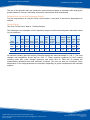
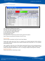
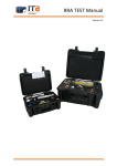
PROPRIETARY INFORMATION
Engines for Thin Film Innovation
NorthStar™ ALD Operation Manual
THIS DOCUMENT CONTAINS PROPRIETARY INFORMATION OF SVT ASSOCIATES, INC.
AND SHALL NOT BE USED, DISCLOSED OR REPRODUCED, IN WHOLE OR IN PART,
WITHOUT THE PRIOR WRITTEN CONSENT OF SVT ASSOCIATES, INC.
7620 Executive Drive | Eden Prairie, MN 55344-3677 | USA
Phone: 952-934-2100 | Fax: 952-934-2737 | Email: [email protected] | www.svta.com
SVT Associates Proprietary Information
©2012 SVT Associates, Inc. All Rights Reserved
Page 1 of 11
Engines for Thin Film Innovation
PROPRIETARY INFORMATION
Table of Contents
ALD System Operation ............................................................................................................................. 3
ALD Operation Principle ........................................................................................................................ 3
Depositing a film using ALD ...................................................................................................................... 4
Preparation ............................................................................................................................................ 4
Establish Good Vacuum and Temperature Stability .............................................................................. 5
Set up a Recipe ..................................................................................................................................... 5
Run the Recipe ...................................................................................................................................... 6
Extract the Substrate ............................................................................................................................. 6
ALD System Safety ................................................................................................................................... 7
Safety Interlocks .................................................................................................................................... 7
Precursor Bubbler Handling .................................................................................................................. 7
Heating up a Bubbler ............................................................................................................................. 8
Mechanical Pump Safety/Maintenance ................................................................................................. 8
Emergency Shutdown Procedure .......................................................................................................... 8
ALD System Shutdown for Extended Period of Time ............................................................................... 9
Complete System Shutdown ................................................................................................................. 9
Precautions ........................................................................................................................................... 9
Chamber Cleaning ................................................................................................................................ 9
Warranty and Limitations of Remedies ................................................................................................... 10
Return Policy ........................................................................................................................................... 10
Returning Equipment for Repair or Servicing ......................................................................................... 11
7620 Executive Drive | Eden Prairie, MN 55344-3677 | USA
Phone: 952-934-2100 | Fax: 952-934-2737 | Email: [email protected] | www.svta.com
Version 12.09.26
SVT Associates Proprietary Information
©2012 SVT Associates, Inc. All Rights Reserved
Page 2 of 11
Engines for Thin Film Innovation
PROPRIETARY INFORMATION
ALD System Operation
Read all of the manuals, including the Safety sections, prior to operating the system.
ALD Operation Principle
Atomic Layer Deposition (ALD) is a vapor phase technique that deposits thin films sequentially, atomic
layer by layer. ALD has been described in the literature. It is based on sequential reactions of vapor
phase chemicals with the surface of the substrate. The reactions are self-limiting. The surface is first
saturated with one chemical precursor, and the excess pumped away. It is then exposed to a second
chemical precursor, and the excess is pumped away. The technique provides excellent coverage of
topographical features. Relative to other techniques, in its standard mode, the deposition rate is slow.
For more information on ALD, see review articles in the literature, such as; Atomic Layer Deposition: An
Overview by Steven M. George, Chem. Rev. 2010, 110, 111–131
As an example of a thermal ALD process, Al2O3 can be deposited using precursors of trimethylaluminum
(TMA) and water. Alternative recipes and recipes for other materials can be found in the literature.
The substrate is introduced into the deposition chamber, which is evacuated. The surface of the
substrate is hydroxylated from exposure to the atmosphere.
One cycle of the deposition sequence can be described as following two half reaction cycles.
1. TMA pulse is admitted into the chamber and allowed to react with hydroxyl groups on the surface.
This reaction proceeds until the surface reaction reaches completion
2. The unreacted TMA is pumped away with the help of an inert carrier gas such as Nitrogen or
Argon.
3. A water pulse (H2O) is admitted into the chamber. The H2O reacts with the surface, removing the
CH3 groups (CH4 (methane) is formed as a gaseous byproduct), creating Al-O-Al bridges, and
passivating the surface with Al-OH once again on the surface.
4. The unreacted H2O and gaseous byproduct CH4 are pumped away with the help of the inert
carrier gas.
These 4 steps of the cycle can be set up in a recipe as a loop. Each cycle produces up to ~1.1 Å (0.11
nm) of Al2O3 depending on temperature. For recipe setup, see the SVT Associates Robo Control User’s
Manual.
The ALD process is distinct from Chemical Vapor Deposition (CVD) in that the reactions occur
sequentially. CVD mode reactions occur when both reacting precursor chemicals arrive on the surface in
the ALD chamber at the same time, and not sequentially. To avoid undesired spurious CVD reactions, it
is critical that the purging steps be complete (sufficient time) and all excess precursor be pumped away
before pulsing of the second precursor. Only one of the precursors should be exposed to the substrate at
a time. CVD reactions in the ALD system will produce non-uniform and excessive deposits.
7620 Executive Drive | Eden Prairie, MN 55344-3677 | USA
Phone: 952-934-2100 | Fax: 952-934-2737 | Email: [email protected] | www.svta.com
Version 12.09.26
SVT Associates Proprietary Information
©2012 SVT Associates, Inc. All Rights Reserved
Page 3 of 11
Engines for Thin Film Innovation
PROPRIETARY INFORMATION
Depositing a film using ALD
NorthStar ALD system may be operated in either the thermal ALD or the plasma enhanced ALD methods.
There are two modes of operation in the thermal ALD method:
1. Regular mode with continuously flowing carrier gas and pulsing precursor chemicals while
continuously pumping.
2. Soak mode for very high aspect ratio structures: Pulsing a precursor with the exhaust valve
closed to allow sufficient exposure and saturation of all the surfaces, and then opening the valve
to pump/purge. This is then repeated for the other precursor.
In thermal mode, a small internal chamber with lid is preferred.
Plasma enhanced ALD mode (PEALD) – A remote plasma source is designed to enhance the reactivity
of many gas species such as N2, O2, H2, NH3, etc. and lower growth temperatures. A reactive gas,
sometimes balanced with Ar in order to boost plasma efficiency is used. PEALD and thermal ALD can be
switched easily by removing or putting on an internal lid.
Key growth parameters include precursor pulse time, pulse strength, and purge time for each precursor.
Carrier gas and sealing gas flow rates are also important. There are parameter tradeoffs in an ALD
process. Longer precursor pulse times can assure that the surface to be coated is saturated with the
precursor, but precursor consumption will go up and cycle time is prolonged. Higher carrier gas flow
rates help purge the excess precursor faster but may increase base pressure in the chamber thus
reducing precursor pulse strength.
In the NorthStar ALD system there is an internal deposition chamber within the vacuum chamber. A flow
of inert gas from the top of the chamber into the outer chamber space is used as a “sealing gas” in the
thermal mode to help seal the internal lid and suppress precursor from leaking out of the internal
chamber.
Preparation
Make sure the system has been properly outgassed:
• run the in-vacuum heaters at >100 ºC to outgas all internal surfaces
• the precursor bubblers should be installed and any headspace between the manual shutoff
valves and the ALD valves evacuated.
Check and make sure the cooling water line o-rings for the Growth Chamber and the Plasma Source are
sealing. Make sure the carrier gas and gases for the Plasma source are ready.
Power up the system, pumps, and computer. Start the Robo Control software program and turn on the
system electronics.
Prior to any use of chemical precursors, the Hot Trap should be on and operating. Leave the Hot Trap on
during the use of precursors.
If you are working in the thermal ALD mode, the internal lid cover must be in place and properly sealed; if
you are working in plasma enhanced ALD mode, remove the internal lid or insert.
Introduce the Substrate into the ALD Chamber – Vent the deposition chamber to atmosphere and open
the outer vacuum chamber lid. Internal surface should be kept >100 °C to suppress moisture adsorption
during exposure to atmosphere. Caution: to avoid injury, avoid touching hot surfaces. Place the
substrate on the pedestal. Close the lid and evacuate the system.
7620 Executive Drive | Eden Prairie, MN 55344-3677 | USA
Phone: 952-934-2100 | Fax: 952-934-2737 | Email: [email protected] | www.svta.com
Version 12.09.26
SVT Associates Proprietary Information
©2012 SVT Associates, Inc. All Rights Reserved
Page 4 of 11
Engines for Thin Film Innovation
PROPRIETARY INFORMATION
The use of the optional Load-Lock Introduction system allows exchange of substrates while keeping the
growth chamber in vacuum, minimizing exposure to moisture and other contaminants.
Establish Good Vacuum and Temperature Stability
Turn the lamp heaters on using the Robo control system. It may take 30 minutes for temperatures to
stabilize.
Set up a Recipe
See Robo Control User’s Manual, “Creating Recipes”
The following are two examples of Al2O3 deposition recipes in both thermal and plasma enhanced modes
for your reference.
Outer
Carrier
Ar
Chamber Internal
TMAI Pulse
H 2O
Gas Top/Sealing
Gauge Gauge Growth Bubbler
Target
Pulse Strength Purge Pulse Purge Flow Gas Flow
Reading Reading Temp Temp
Materials Mode Time(s) (Torr) Time(s) Time(s) Time(s) (sccm) (sccm)
RF-02
(Torr)
(Torr)
(ºC)
(ºC)
Thermal
Al2O3
ALD
0.02 0.04-0.1 15
0.02
15
4
2
*
1.1
0.17 120-250 RT
RT or
Al2O3 PEALD 0.5 0.04-0.1 30
15
5
10
10
2
0.25
0.2 Higher
RT
*Internal lid or insert on for thermal mode, the lid or insert removed for plasma mode
All manifolds including precursor delivery lines and exhaust line should be heated to >100 °C. The outer
chamber wall temperature should also be >100 °C. These exposure conditions for Al2O3 coating
including pulse time, pulse strength (pressure) and purge time for TMAl and O2 plasma are
experimentally determined and meet saturation conditions. You may use them as a reference. Some
adjustments of the recipe parameters are necessary depending on growth temperatures and individual
systems.
7620 Executive Drive | Eden Prairie, MN 55344-3677 | USA
Phone: 952-934-2100 | Fax: 952-934-2737 | Email: [email protected] | www.svta.com
Version 12.09.26
SVT Associates Proprietary Information
©2012 SVT Associates, Inc. All Rights Reserved
Page 5 of 11
Engines for Thin Film Innovation
PROPRIETARY INFORMATION
An example of a recipe program
Table 1. A sample recipe for PEALD Al2O3 in RoboALD program format
TMAl: ALD valve for TMAl precursor source;
SS1-SS2: ALD valves for spare precursor sources;
CG: carrier gas on/off valve for MFC control;
P1: Auto stop valve for exhaust and pump;
S1-S2: spare function controls;
RF: plasma power control;
RFV: On/off valve for top sealing Ar gas and reactive gases for RF plasma.
See RF Plasma source Manual for operation of the RF source
Run the Recipe
Start the recipe as described in the Robo Control User’s Manual.
Always make certain that the Hot Trap is in operation and at desired temperature before starting a
recipe. Make certain that all utilities such as exhaust abatement and cooling water, etc. are in operation
before starting a recipe.
Upon completion of the recipe, turn off the bubbler manual shutoff valves; set the growth parameters in
the standby mode either manually or by recipe (not provided). Suggested standby conditions include
setting up the substrate temperatures to >100 °C for overnight, running low carrier gas flow constantly.
Extract the Substrate
Reverse the procedure of introducing a sample.
7620 Executive Drive | Eden Prairie, MN 55344-3677 | USA
Phone: 952-934-2100 | Fax: 952-934-2737 | Email: [email protected] | www.svta.com
Version 12.09.26
SVT Associates Proprietary Information
©2012 SVT Associates, Inc. All Rights Reserved
Page 6 of 11
Engines for Thin Film Innovation
PROPRIETARY INFORMATION
ALD System Safety
Safety Interlocks
The system has 3 safety interlocks to handle possible emergency situations
1. Growth chamber interlock – If the growth chamber has any leaks or the pressure rises above a
set level (say 5 Torr) in the middle of the growth process, the controller and the pneumatic throttle
valve software can automatically shut down and isolate all ALD valves and MFCs so no precursor
vapor or by product can leak into the growth chamber or leak outside if the system is vented.
2. Emergency stop button – There is a manual stop button. In case of an emergency, push the
emergency stop button. All ALD valves, MFCs and the pneumatic throttle valve will shut down
and the growth chamber is sealed to prevent any possible precursor vapor leaking outside.
3. Exhaust for the console – There is an exhaust port for the console. All precursor bubblers are
located in the console. In case of precursor bubbler leakage, the exhaust can prevent the vapor
from leaking outside. Make sure both front and back doors of the console are properly closed at
all the times to maximize the exhaust flow.
It is strongly recommended that a gas sensor/alarm system working for a specific vapor material be
installed near the ALD system. For example, if you work with chloride such SiCl4 material, an HCl sensor
should be installed inside the console or near the growth chamber.
Precursor Bubbler Handling
The source of the precursor chemicals is generically referred to as a “bubbler”. A bubbler passes a
carrier gas through a liquid chemical to pick up the chemical. Alternatively, for high vapor pressure
materials, it is not necessary to pass the carrier gas through the liquid, but simply have a cylinder of the
material, at a controlled temperature, which feeds directly into the ALD valve, called direct vapor drawing.
Know the nature of the precursors with which you are working and read the Material Safety Data Sheet
(MSDS), which is available from the chemical supplier. Many ALD precursors are flammable, corrosive or
toxic. For example, TMA is pyrophoric; it burns upon exposure to air. It is thus crucial to handle the
precursor bubblers safely, which includes knowing how to connect and disconnect a bubbler to the ALD
valve and how to store a bubbler if it is not in use.
When connecting a filled bubbler to an ALD valve, make sure to wear a proper mask or respirator, clear
the ALD area of irrelevant personnel; double check to make sure the manual on/off valve on the bubbler
is closed tightly before loosening the VCR fitting; Loosen the VCR sealing cap in a chemical hood with
proper vent system. Ideally there should be a gas sensor around to check if there is a possible leakage
from the bubbler. Immediately transfer the bubbler to the ALD console and connect to the ALD fitting,
and tighten it. Make sure the line between ALD valve and the bubbler is purged, by opening the ALD
valve for a short period of time before you open the manual on/off switch (assuming the system is under
vacuum). If the base pressure is not recovered and is higher than the original point, there could be
leakage from the bubbler connecting area.
When disconnecting a filled bubbler from an ALD valve, make sure to wear proper mask or respirator,
clear the ALD area of irrelevant personnel; double check to make sure the manual on/off valve on the
bubbler is closed tightly before loosening the VCR fitting; purge the line between ALD valve and the
bubbler to remove any residual precursor in the line; loosen the connecting fitting and cap the bubbler
immediately with a VCR cap and gasket.
7620 Executive Drive | Eden Prairie, MN 55344-3677 | USA
Phone: 952-934-2100 | Fax: 952-934-2737 | Email: [email protected] | www.svta.com
Version 12.09.26
SVT Associates Proprietary Information
©2012 SVT Associates, Inc. All Rights Reserved
Page 7 of 11
Engines for Thin Film Innovation
PROPRIETARY INFORMATION
When a filled precursor bubbler is taken out of use, it is the best to put it back in the original package and
store in a safe, properly vented area or chemical hood area. Make sure the on/off valve is tightly sealed
and the VCR cap is tightened.
Heating up a Bubbler
Depending on precursor volatility, a bubbler sometime has to be heated to certain temperatures to get
sufficient vapor pressure (~1 Torr), for example Hf precursors of TDMAH, TEMAH and TDEAH. Please
pay attention to the key properties such as working temperature, decomposition temperatures and
maximal ALD growth temperature of the precursor used. This information may be found in the literature.
Make sure the thermocouple of a bubbler heater has good thermal contact with the bubbler, and has
good measurement stability and accuracy so that the temperature readings are real; ensure the working
temperature never goes beyond the decomposition temperature; in addition, when heated, it is
recommended that you keep the precursor constantly at the working temperature or slightly below, this
minimizes the thermal cycling of a precursor to avoid degradation.
Mechanical Pump Safety/Maintenance
1. In principle the ALD process should work in a slightly over-saturated exposure condition, and
almost 100% of the precursors are consumed and very little excessive vapor going into the
exhaust and the pump. The saturation condition for an ALD system has to be experimentally
determined. However, if precursor vapor pulses are oversaturated too much or too excessively, or
there is not sufficient purge, a severe CVD reaction can happen which generates a lot of powders
or particles inside the growth chamber, down the exhaust and even into the pump. It is thus
strongly recommended that you use recipes approved by SVT Associates or minimize precursor
use to avoid exhaust problems. This is the fundamental, the most important, root protection for
the pump;
2. In practice, it is hard to identify exact saturation conditions or it takes many test runs.
Condensation of excessive precursors, particles or other by-products could still be built up
gradually along the exhaust line or even precursor delivery lines. If the exhaust line is heated and
there is not any filter or trap installed down the exhaust line, most are dumped in the pump. A hot
trap or filter is needed which becomes the secondary defense line. A hot trap is capable of
decomposing or neutralizing excessive metal organic precursor vapor into less volatile products
and hydrocarbon gas, which do not harm the pump and reduce hazard.
3. A chemical corrosive resistant pump/use of Fomblin oil are recommended. Fomblin is ideal but
expensive. However it is a trade off of the oil price and pump repair cost. If ordinary mechanical
oil is used, frequent replacement is necessary (once a month or even more frequent if in heavy
use or very aggressive chemicals are used). Some other types of pump oil which are resistant to
O2/H2O and metal organics such as AJ Elite Z synthetic vacuum pump fluid from A&J vacuum
can last longer than the ordinary one.
Emergency Shutdown Procedure
In an emergency situation such as system malfunction, power shut down, system vent failure:
• Stop the program if you are in the middle of the growth;
• Manually shut down shutoff valves of all bubblers in use;
• When the RF plasma unit is on, turn off, zero all MFCs and switch off all master pneumatic valves
to prevent any gas in; and shut down the gas cylinder;
• Shut down the lamp heater, manifold heater, exhaust heater and chamber wall heater;
• Close the automatic throttle valve to isolate from the pump and shut down the pump itself
manually.
• Identify the reason of the failure or malfunction and correct it before restarting the system
7620 Executive Drive | Eden Prairie, MN 55344-3677 | USA
Phone: 952-934-2100 | Fax: 952-934-2737 | Email: [email protected] | www.svta.com
Version 12.09.26
SVT Associates Proprietary Information
©2012 SVT Associates, Inc. All Rights Reserved
Page 8 of 11
Engines for Thin Film Innovation
PROPRIETARY INFORMATION
ALD System Shutdown for Extended Period of Time
Certain ALD precursors can degrade with repeated heat and cool cycles.If precursors must be cooled, or
are accidentally cooled as a result of a power failure, we recommend the precursors remain at room
temperature until needed to run process.
Complete System Shutdown
• Confirm that the manual precursor isolation valves are closed.
• Close manual gate valve between chamber and loadlock
• Set all MFC flows to 0 sccm
• Close Process gas isolation valves
• Shut off all heaters (Lamp heater, chamber wall heater, manifold heaters, exhaust heater, hot
trap, and precursor heaters)
• Close load-lock roughing valve
• Close chamber pumping gate valve
• Turn off the turbo pump, leave the Turbo backing pump run until the turbo stops spinning
• Turn off the load-lock rough pump
• Power down Eurotherms, RF power supply, Ozone generator
• Turn off water
• Close air supply to system
• Close Robo program
• Shut off computer
• Remove main power to the system
Precautions
Do not heat the ALD system to temperatures above those recommended by the manufacturer. Note the
maximum temperature settings for different parts. ALD pulse valves are rated to 200 ºC and should not
be heated above that temperature. The lamp heater maximum temperature is 500 ºC, while outer
chamber wall heaters should not be set > 150 – 200 ºC because of the o-ring. The precursor delivery
lines and exhaust lines should not be heated above 200 ºC. Temperature of the precursors should not
exceed safety or decomposition temperature of the chemical used. The maximum temperature for the
precursor heater jacket is 200 ºC.
Chamber Cleaning
After many depositions are performed in the ALD system, deposits build up on the internal surfaces.
Depending on the materials deposited, thermal cycling of the system can eventually cause cracking and
flaking of the deposit. If flakes are visible, clean the chamber with a lint free cloth using the appropriate
solvents.
On systems that are equipped with the plasma source, an Oxygen plasma can be used to clean (by
combustion) excessive organic deposits in the chamber. Similarly, a Hydrogen plasma can be used to
prepare an ALD chamber for nitride deposition to suppress oxygen inclusion into the film.
7620 Executive Drive | Eden Prairie, MN 55344-3677 | USA
Phone: 952-934-2100 | Fax: 952-934-2737 | Email: [email protected] | www.svta.com
Version 12.09.26
SVT Associates Proprietary Information
©2012 SVT Associates, Inc. All Rights Reserved
Page 9 of 11
Engines for Thin Film Innovation
PROPRIETARY INFORMATION
Warranty and Limitations of Remedies
SVT Associates warrants that all equipment manufactured by it shall be free from defects in materials
and workmanship under normal use and service for a period of twelve (12) months from the date of
shipment from SVT Associates manufacturing facility. This warranty is subject to SVT Associates
equipment being installed, maintained, and operated in accordance with the operating and maintenance
instructions accompanying each item manufactured by SVT Associates. Warranty shall be void if SVT
Associates equipment is modified by the CUSTOMER or used in other than the recommended manner or
applications. Purchased equipment incorporated into any item supplied by SVT Associates will be
covered by said manufacturer’s warranty.
SVT Associates warrants that, at the time of delivery, any other products processed or manufactured and
sold by it hereunder are free of defects in material and workmanship and conform to COMPANY
specifications. No warranty is provided by SVT Associates for products sold hereunder which are not
manufactured or processed by SVT Associates, but the manufacturer’s warranty for such products, if
any, shall be assigned to the CUSTOMER without recourse to SVT Associates The foregoing warranties
are in lieu of and exclude all other warranties not expressly set forth herein, whether expressed or
implied by law or otherwise, including without limitation any warranty of merchantability or fitness for a
particular purpose. In no event will SVT Associates be liable for any consequential damages.
IN THE EVENT OF SVT ASSOCIATES LIABLITY, WHETHER BASED ON CONTRACT, TORT
(INCLUDING BUT NOT LIMITED TO NEGLIGENCE AND STRICT LIABLITY) OR OTHERWISE, THE
CUSTOMER’S SOLE AND EXCLUSIVE REMEDY WILL BE LIMITED; SVT ASSOCIATES HAS THE
FOLLOWING OPTIONS; TO REPAIR OR REPLACEMENT (F.O.B. SVT ASSOCIATES
MANUFACTURING PLANT) BY THE COMPANY OF ANY NON-CONFORMING ITEM FOR WHICH
CLAIM IS MADE BY THE CUSTOMER OR TO REPAYMENT OF THE PORTION OF THE PURCHASE
PRICE PAID BY THE CUSTOMER ATTRIBUTABLE TO THE NON-CONFORMING ITEM. SVT
ASSOCIATES WILL NOT BE LIABLE FOR ANY OTHER DAMAGES, WHETHER DIRECT,
INCIDENTAL, CONSEQUENTIAL OR OTHERWISE.
Return Policy
Any request by the CUSTOMER for return of standard products other than for warranty claims under
warranty hereof, for all or any part of purchase order accepted by SVT Associates, shall be subject to the
following conditions:
A. Notification must be made to SVT Associates by the CUSTOMER within thirty (30) days of
original shipping date.
B. A “RETURN GOODS AUTHORIZATION” number must be assigned to and accompany all goods
or materials being returned by the CUSTOMER to SVT Associates. Said number must be
assigned by SVT Associates prior to any and all returns. Goods not accompanied by a “RETURN
GOODS AUTHORIZATION” number will be refused by SVT Associates and returned at the
CUSTOMER’S expense.
C. CUSTOMER shall prepay shipping charges for products being returned to SVT Associates.
D. Products being returned to SVT Associates should be properly crated for shipment, and the
CUSTOMER shall bear the risk of loss until delivered to SVT Associates.
E. Products being returned to COMPANY must be returned in the condition originally received by
the CUSTOMER and free from damage, use or modification which would render the product
unusable for resale by SVT Associates.
F. All applicable taxes, duties, insurance, and shipping charges shall be the sole responsibility of the
CUSTOMER.
7620 Executive Drive | Eden Prairie, MN 55344-3677 | USA
Phone: 952-934-2100 | Fax: 952-934-2737 | Email: [email protected] | www.svta.com
Version 12.09.26
SVT Associates Proprietary Information
©2012 SVT Associates, Inc. All Rights Reserved
Page 10 of 11
Engines for Thin Film Innovation
PROPRIETARY INFORMATION
G. Goods being returned for other than warranty repair shall be subject to a restocking charge of
twenty (20) percent of the original sales price of the returned item.
Returning Equipment for Repair or Servicing
Before shipping equipment for repair or servicing, obtain a Return Authorization Number assigned by
SVT Associates, Inc.
Liability Disclaimer
SVT Associates, Inc. takes steps to assure that its published specifications and manuals are correct; however,
errors do occur. SVT Associates, Inc. reserves the right to correct any such errors and disclaims liability resulting
therefrom.
No Liability for Consequential Damage
In no event shall SVT Associates, Inc. or anyone else involved in the creation, production, or delivery of the
accompanying product (including hardware and software) be liable for any damages whatsoever (including, without
limitation, damages for loss of business profits, business interruption, loss of business information, or other
pecuniary loss) arising out of the use of or the results of use of or inability to use such product, even if SVT
Associates, Inc. has been advised of the possibility of such damages.
7620 Executive Drive | Eden Prairie, MN 55344-3677 | USA
Phone: 952-934-2100 | Fax: 952-934-2737 | Email: [email protected] | www.svta.com
Version 12.09.26
SVT Associates Proprietary Information
©2012 SVT Associates, Inc. All Rights Reserved
Page 11 of 11