1
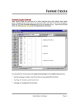
Cipher-201
Programmable
Terminal
User’s Guide
CipherLab Co., Ltd.
1
1. Packing
This packing includes:
(1)
This User's Guide
(2)
The Cipher-201 main unit
(3)
Optional LCD display and Calendar of Cipher-520
main unit(by order)
(4)
Power Adaptor (110VAC or 220VAC)
(5)
Default System Master Card (1234567890)
2
2. Components
2.1. Front View
C1
DC Jack
C2
Power
Switch
Speaker
Ready LED
LCD
Good Read
LED
JP10
Reader 1
AUX232
Reader 2
External/Keyboard
Note:
The data memory can be a 32KB or 128KB SRAM. However, to
accommodate different pin assignments, The SRAM type must
be selected via the jumper (JP10) on the main board.
3
3. Installation
3.1. Power Source
The Cipher-201 can be powered 8 to 20V from the DC jack and +5V from
C1 or C2. In case this host power is not available or not adequate, a wall
adaptor (in the range of 8 to 20V) can be fed via the DC-jack.
3.2. Reader Ports
There are totally 2 reader ports provided, each can be either a Wand,
Barcode slot reader, Barcode Scanner with Laser emulation or up to
dual-track magnetic card reader.
3.3. External Keyboard Port
An external AT-compatible keyboard can be attached for handy data
entry. The connector and pin assignment conforms to PC/AT
standards.
3.4. RS232 Connection
The factory settings of the RS232 port are 9600 baud rate with 8 data
bits, no parity, and 1 stop bit. And the Cipher-201s delivered from
factory all have the line connection setting been set to multi-station
on-line master. User can use Aux232 or C1 or C2 to connect
computer and transfer data.
4
AUX232
RS232
C2
C1
RS-232 Configuration
3.5. RS485 Connection
The RS485 ports are used to connect multiple Cipher-201s. Every
Cipher-201 station is connected to the RS485 bus line in a daisy
chain style.
PC
RS232
RS485
C2
RS485
Connect Others
C1
RS-485 Connection between Cipher-201s
5
3.6. Digital I/O
The Cipher-201 provides 2-digitsal inputs and 2-digitsal outputs for
controlling and monitoring external devices. These inputs and outputs
are photo-isolated and share the same DB-25 connector as the
COM2
13. Digital Output 1
14. Digital Output 0
15. Digital Input 1
16. Digital Input 0
COM2 Port Connector and Digital Pin Assignment
3.7. Speaker
A low power speaker is supported and the sound level is 4-level
tunable. This speaker electrically behaves like a capacitor, which
implies
that
current
flows
only
when
states
are
changed
(charge/discharge capacitor) and very little power is consumed.
However, a higher voltage, e.g. 10V is needed to drive it.
3.8. LED Indicator
There are totally 2 LEDs on the panel for showing system
status.
⋅
⋅
READY, Red
GOOD READ, Green
6
3.9. LCD Display
A 2 x 20 LCD is used to display current system time, scanned card ID,
system message and so on. This is an easy-to-read wide viewing
angle LCD equipped with LED back light and can easily be read even
in a dim environment. The viewing angle can be adjusted via a
variable resistor as depicted in the Nomenclature.
7
4. Programming System Parameters
The system parameters of Cipher-201 Terminal can be programmed
manually or by RS232 commands. Manually programming the Cipher-201
terminal system is described in this section and programming the Cipher-201
via RS232 commands will be described under the section RS232
Command.
4.1. Manually programming
Power on the Cipher-201 and scan the master card. Now Cipher-201
is waiting for entry of the password. However, if the password was set
to none, this message will not be shown and this step is simply
ignored. The system manager must key in the password now. If the
password is correctly entered, Cipher-201 will be in the System
Management mode where 2 major tasks can be done as follows,
1. Setup
System Manager
1.Setup
(1) Press the ENTER key and now the Cipher-201 is in the setup
mode and is ready to accept system parameter modification.
The Cipher-201 will show the name of parameter on the upper
side of the display and the original setting value on the lower
side.
2. Line Connection:
=Master
(2) Press ENTER key then you can change the setting value of
this parameter. Use the ” ” and “ ” keys for selecting a new
setting value or type in a new value via numeric keys. Then
press ENTER key to conclude the new setting value.
1. Line Connection:
-><Single>
(3) After all the system parameter modification are completed, the
F1 key must be pressed to update these modifications and
8
save the new settings into the program memory. System will
restart with the new settings. If F2 key instead of F1 key is
pressed, all modifications of the system parameters will be
discarded and retain the original settings.
(4) Followings are the system parameters,
a. Station ID Setting
b. Line Connection Setting
c.
Max. Station ID Setting
d. Manager Card Setting
e. Manager Password Setting
f.
LCD backlight Setting
g. Master Card Setting
h. Password Setting
i.
Buzzer Volume Setting
j.
Time Setting
k.
Timer Fine Tune Setting
l.
COM1 Setting
m. COM3/AUX Setting
n. Sybologies Setting
o. Rdader1 Setting
p. Reader2 Setting
q. Time Stamp Setting
r.
ID Stamp Setting
s.
Source Stamp Setting
2. Self Test
This mode provides a simple but yet efficient way for diagnostic.
Press
ENTER key for executing the following items test one by one,
⋅
⋅
⋅
⋅
Flash test
SRAM test
Beeper test
LCD test
9
⋅
⋅
⋅
⋅
⋅
⋅
⋅
⋅
⋅
⋅
⋅
⋅
⋅
LED test
DI & DO test
COM1 test
COM2 test
COM3 test
485 test
Wedge test
ADC test
Calendar test
Reader test
Keypad test
AT Keyboard test
Shutdown test
3. Init System
This is used to set all system parameters to their default value
and initialize the file systems. Care should be taken, as this
will destroy all data stored in the memory.
4. Flash Clone
This is used to copy the program in FLASH memory to another
terminal. Usually it is used for diagnostic or software update.
5. Flash Download
This is used to update program code stored in the flash memory.
The code can be downloaded from a PC using the “MDL6” or as
described in the previous section, from another machine. Also,
the RS232 has been fixed to 38400,N,8.
10
4.2. Host Command
The host computer can get access to terminals on the RS485 nets via
COM1 of the master station.
Basic characteristics of the Cipher-201 are listed below,
4.2.1 Command Format
Each command is composed as <CC><ss><p..p>^,where,
<CC>
command code string
<ss>
2 digits station ID depending on command code
<p..p>
parameters
^
delimiter carriage return, hex 0d
4.2.2 Command for master station
The following commands are for master station only and thus NO station ID
should specified.
Command
Code
ONLINE
Parameter Operation
Echo
null
inquire on-line-status
READ
null
read one record
REMOVE
null
remove one record
MAXID
null or =ss inquire/set maximum
station IDs to be polled
null or
inquire/set system time
=YYMMD
Dhhmmss
aa,bb,..,cc
lists of all station Ids that are
currently on-lined including the
master station itself
d…d: if available
OVER: if empty
NEXT: done
OVER: done and data file now
empty
ss: 2 digits maximum ID
TIME
YYMMDDhhmmss: system time
after command execution. Once
set, all stations on the net are
11
modified.
Note:
1. The command REMOVE is effective only after current record has been read by
Command READ, else the data file remains unchanged even NEXT is echoed.
2. When command TIME was issued, the master automatically issues a broadcasting
Command to update all stations.
^
4.2.3
delimiter carriage return, hex 0d
Command for Individual station
Individual station can be accessed via these commands and 2-digit station ID MUST be
specified.
Command
Parameter
Operation
Echo
inquire on-line status
aa,bb,..,cc
Code
DCOUNT null
stored in the data file
TTUNE
null or = offset inquire/fine tune calendar
d..d: value of the tuning register
offset = offset value from
–128 to +127
MCARD
null or = tm..m inquire/set master card
tm..m: updated master card
t: code type
m..m: up to 20 characters
card ID
PWD
null or = p..p
inquire/set password
p..p: updated password
BL
null or = d
inquire/set backlight level
d: updated backlight level
d: 0 to 3
VOL
null or = d
inquire/set buzzer volume
d: updated buzzer volume
12
d: 0 to 3
COM1
null or = b,p,d,h inquire/set COM1 setting
b,p,d,h: updated settings
b: baud rate from 0 to 7
p: parity from 0 to 3
d: data bits from 0 to 1
h: handshake from 0 to 3
COM3
null or = b,p,d,h inquire/set COM3 setting
b,p,d,h: updated settings
b,p,d,h: as above
BCODE
null or = p..p
inquire/set symbologies
p..p: updated setting
p..p: 20 digits for each
symbologies
READER1 null or = s,t,r
inquire/set reader1
s,t,r: updated setting
s: scan mode from 0 to 7
t: time out from 0 to 225
r: redundancy from 0 to 3
READER2 null or = s,t,r
inquire/set reader 2
s,t,r: updated setting
s,t,r: as above
TMSTP
null or = d
inquire/set time stamp
d: update setting
d: 1/0, enable/disable
IDSTP
null or = d
inquire/set IDstamp
d: update setting
d: 1/0, enable/disable
SRSTP
null or = d
inquire/set source stamp
d: update setting
d: 1/0, enable/disable
13
Cipher-201
Hardware Reference Manual
V1.1
April 18, 2007
© 1995, CipherLab Co., Ltd.
Cipher-201 Hardware Reference Manual
1.
Table Of Contents
1. Table Of Contents .................................................................................................2
2. List Of Figures......................................................................................................3
3. Preface..................................................................................................................4
4. General Features ...................................................................................................5
5. Characteristics.......................................................................................................6
5.1. Electrical...................................................................................................6
5.2. Environmental...........................................................................................6
5.3. Physical ....................................................................................................6
6. Nomenclature........................................................................................................7
7.PCB .......................................................................................................................8
8. Power Circuit ........................................................................................................9
9. Reset ...................................................................................................................10
10. Program Memory (Flash) ..................................................................................11
11. Data Memory (SRAM)......................................................................................12
12. Calendar chip ....................................................................................................13
13. Memory and Calendar Backup Battery ..............................................................14
14. LCD..................................................................................................................15
15. Reader...............................................................................................................16
16. External Keyboard ............................................................................................17
17. Membrane Keypad ............................................................................................18
18. Interface C1 ......................................................................................................19
18.1. COM2...................................................................................................20
18.2. Wedge emulation ..................................................................................20
18.3. Power Pins ............................................................................................20
18.4. Loop Back Tester ..................................................................................20
19. Interface C2 ......................................................................................................21
19.1. COM1...................................................................................................22
19.2. Digital Input..........................................................................................22
19.3. Digital Output .......................................................................................22
19.4. Power Pins ............................................................................................22
19.5. Loop Back Tester ..................................................................................23
20. RS232 (COM3).................................................................................................24
21. LED ..................................................................................................................25
22. Speaker .............................................................................................................26
Table Of Contents
Cipher-201 Hardware Reference Manual
2.
List Of Figures
Figure 1. Nomenclature.............................................................................................7
Figure 2. PCB ........................................................................................................8
Figure 5. SRAM type selector ..............................................................................12
Figure 6. SRAM connection.................................................................................12
Figure 7. LCD Connector.....................................................................................15
Figure 8. Reader 1 Connector...............................................................................16
Figure 9. External Keyboard Connector ...............................................................17
Figure 10. Keypad Connector...............................................................................18
Figure 11. C1 .......................................................................................................19
Figure 12. C2 .......................................................................................................21
Figure 13. COM3 .................................................................................................24
Preface
Cipher-201 Hardware Reference Manual
3.
Preface
This manual provides in-depth hardware informations of the Cipher-201 programmable
terminal and serves as a reference for hardware and maintenance engineers. Assumption
has been made that readers of this manual have basic knowledge of electric and/or
electronic theory.
Numberings of all components, including connectors, passive and active components
conforms to the PCB V3.01. However, CipherLab does not guarantee this conformity.
The numberings and locations of components might be re-arranged. For confirmation,
please refer to the PCB and its schematics. After all, this manual intends to describe the
operation theory of the circuitry utilized.
Preface
Cipher-201 Hardware Reference Manual
4.
General Features
The Cipher-201 is equipped with the follows,
• TLCS-900 16 bit CPU running at 9.8304 MHz
• Program : 128 KB flash memory
• Data memory : 32 or 128 KB SRAM
• Optional Fine-tunable calendar chip
• Memory & calendar chip backup 3.6V NiCd battery
• 2 reader ports for barcode Wand, Laser-emulation scanners or up to dual-track
magnetic card reader.
• optional 2 X 20 characters dot-matrix LCD display with adjustable back-light
and viewing angle
• optional 4 X 4 membrane keypad
• 2 digital input ports
• 2 digital output ports
• external keyboard port (AT keyboard) or keyboard emulation
• 3 serial communication ports, depending on ports, can be configured as RS232,
CMOS RS232 or RS485
General Features
-5-
Cipher-201 Hardware Reference Manual
5.
Characteristics
Basic characteristics of the Cipher-201 are listed below,
5.1. Electrical
Main Power Supply Voltage :
• 8 to 20 V DC from DC-jack
• +5V from C1 or C2
Power consumption : 0.5W maximum without LCD nor external devices attached
•
•
5.2. Environmental
•
•
•
•
•
Humidity (operating) : non-condensed 20% to 90%
Humidity (storage) : non-condensed 10% to 95%
Temperature (operating) : 0 to 50
Temperature (storage) : -20 to 70
EMC regulation : FCC class A and CE approved
5.3. Physical
•
•
•
•
Dimensions : 179 * 116 * 32 mm (without LCD)
Weight : 300 gram maximum (without LCD)
Material : ABS
Color
: Gray
Characteristics
-6-
Cipher-201 Hardware Reference Manual
6.
Nomenclature
The overall out-looking and connector locations are depicted below,
C1
DC JACK
C2
POWER SWITCH
SPEAKER
READY LED
GOOD READ LED
AUX 232
READER 1
READER 2
EXTERNAL KEYBOARD
Figure 1.
Nomenclature
Nomenclature
-7-
Cipher-201 Hardware Reference Manual
7.
PCB
The PCB and locations of major components are shown below,
C2
C1
DC-Jack
Power
Switch
LCD
Connector
flash
Speaker
SRAM
JP10
Keypad
Battery
Reader 1
Reader 2
External
Keyboard
Figure 2.
PCB
Aux
RS232
PCB
-8-
Cipher-201 Hardware Reference Manual
8.
Power Circuit
The 201 can be powered in two ways,
• 8 to 20 V from the DC jack
• +5V from C1 or C2
Later is used mostly for keyboard emulation decoders where the power can be drawn
from the host computer. In case this host power is not available or not adequate, an wall
adapter (in the range of 8 to 20V) can be fed via the DC-jack. As long as this external
power is asserted, the +5V from C1 or C2 is disconnected via an internal FET switch. A
simple buck-type switching regulator (LM2575) is followed to generate the required
system power, +5V. This regulator is capable of providing up to 1 Amp currents and
provides a reasonable typical efficiency around 70% to 80%. Low-ESR (equivalent
series resistance) type electrolytic capacitors are used both at input and output sides to
reduce ripples.
-
+
Figure 3.
Main Power Connector
The power is controlled via a dual pole dual throw (DPDT) type switch and a resistor is
used to discharge the output capacitor when switch was turned off (namely, to the OFF
side). As the 201 itself consumes very little power (typical 50mA with LCD back-light
off, no external devices attached), this ensures a sharp power up and down sequence.
DC/DC
Converter
DC-jack
DPDT
Power
Switch
+5V
Figure 4.
Power Circuit
+5V
FET
Switch
Power Circuit
-9-
Cipher-201 Hardware Reference Manual
9.
Reset
The system reset signal is generated by a voltage detector chip RICO RE5V or
compatible chips. It outputs an active low reset signal when the system power drops
below a pre-determined voltage level (Vdet-). The reset signal then changes to high
when the power is higher than another pre-determined voltage level (Vdet+). The Vdet+
is about 200 mV higher than Vdet-, this phenomenon known as hysteresis, prevents
noise to false-trigger the reset circuitry. The TLCS-900 is guaranteed to work within 5V
10% and the Vdet- is set to 4.6V. This reset signal does not only ensure the proper
operation of the CPU but is also used to reset the UART chip (NS82C50) and disables
SRAM access (connecting to SRAM CE2) during power-up and power-down. The later
is very important as the SRAM contents might be changed by unwanted spikes during
supply voltage change.
Reset
- 10 -
Cipher-201 Hardware Reference Manual
10. Program Memory (Flash)
128 Kbytes flash memory (U2) is used to store the program code and is guaranteed to
last at least 100,000 erase/program cycles. 2 kinds of flash chips can be used, the AMD
29F010 and 28F010 from Intel, MX and so on, and the access time must be 150 ns or
faster. The former is a pure +5V device whereas the later requires a +12V for
erasing/programming. U3 and accompanying passive components are used to generate
this +12V. The U3 can be a Maxim MAX660 or Linear Technology LT1262, which two
are total-compatible. Instead of inductor type switching DC/DC converter, these chips
utilize a capacitor switching type circuitry and features smaller PCB space, lower ripple
and lower EMI emission.
The +12V generation is controlled by a CPU output pin and types of flash memory
utilized is automatically identified by software (refer to software manual, routine
download() ). That is, if 29F010 is used, this circuit is not enabled. During normal read,
this DC/DC converter is disabled and the voltage stays at 0V.
Program Memory (Flash)
- 11 -
Cipher-201 Hardware Reference Manual
11. Data Memory (SRAM)
The data memory can be a 32KB or 128KB SRAM. However, to accommodate
different pin assignments, the SRAM type must be selected via the jumper, JP10 as
follows,
256 K Bit
1 M Bit
JP 10
Figure 5. SRAM type selector
Also, the SRAM should be plugged as follows,
1 M Bit
PIN 1
256 K Bit
U1
PIN 3
U1
PIN 1
Figure 6. SRAM type connection
The SRAM used must be LL type to reduce battery power consumption and with access
time 150 ns or faster. These SRAMs are backup by a NiCd battery and will be described
in detail later.
Data Memory (SRAM)
- 12 -
Cipher-201 Hardware Reference Manual
12. Calendar chip
A battery backup calendar chip is used to retain the system time even when power is
off. The chip utilized is a V3022 from EM micro-electronic Marin SA. It features the
following outstanding features,
• Very low power consumption
When powered from the battery (3.6V), the current is typically 0.9 µA and
maximally 1.5 µA.
• Wide operation voltage range
This chip works down to 2.0 V.
• On-chip high precision oscillator
This is a must for accurate time keeping as it is factory trimmed and external
oscillators tend to be effected by outside electro-magnetic noise, temperature and
so on for the long leads and traces.
• Timer Adjustment
It can also be fine tuned to compensate for a fast or slow clock. This is an
outstanding feature for those applications which need punctual system time such
as a time/clock application. The tuning of the calendar chip is done by modifying
the value of the trimming register of the calendar chip.
• Trimming Register
The frequency of the calendar chip can be tuned in units of ppm via a digital
trimming register. The trimming range is from 0 to 255 ppm. The bigger the value
of the trimming register the slower the calendar chip runs. For instance, if the
calendar chip is 1 second slow in one day then the value of the trimming register
should decrease 12 to correctly adjust the calendar chip. During system
initialization, this register is set to 186.
1 sec/ 1 day = 1000000 / (24 hours X 60 min X 60 sec) = 11.57 ppm ~= 12 ppm
• Write-protected
Unless changing calendar time is needed, it is write-protected and won't be
accidentally changed.
• Cold start detection
A cold start bit is set if power loss encountered or first power-on. The software
can then recognize this bit and initialize the calendar chip.
Calendar chip
- 13 -
Cipher-201 Hardware Reference Manual
13. Memory and Calendar Backup Battery
A 3.6V rechargeable NiCd battery is used to backup the SRAM and keeps the calendar
chip running even when system power is off. Its capacity is 60 mAh and is trickle
charged with a typical 1.2 mA current. After fully charged, it is able to sustain for more
than 15 months. For example,
•
SRAM (LL-type, SONY CXK581000), current consumed is
0.7 µA (typical) and 4.0 µA (max., 0 to 40 )
•
V3022 : 0.9 µA (typical), 1.5 µA (max.)
Time (typical) = 60 mAh / (0.7 + 0.9) = 37500 hrs = 1563 days > 52 months
Time (worst) = 60 mAh / (4.0 + 1.5) = 10909 hrs = 455 days > 15 months
Although behaves in similar ways, unlike system power, switching between +5V and
battery is done by 2 transistors and some passive components. This circuit features a
very low leakage (base to collector leakage current of the PNP transistor Q1) back to the
+5V and a low voltage drop (saturated Vce, ~0.2V). This low drop is necessary for most
CMOS chips. If you are interested in this issue, pick up some CMOS chip data sheets.
When system power is supplied, the supply voltage for these chips (SRAM & calendar)
is +5V - Vdrop. Whereas signals are directly from/to CPU and other chips, which are
supplied with +5V. However, for SRAM (a CMOS chip), the upper limit of input signal
is Vdd + 0.5V. If using diodes such as 1N4148 for switching, the voltage drop is also
0.6V which is too large and will damage these chips.
Memory and Calendar Backup Battery
- 14 -
Cipher-201 Hardware Reference Manual
14. LCD
An optional 20 X 2 LCD display can be equipped as follows,
7
P
J
2
6
1
1
5
1
X
0
2
2 X
X
0
,4
4
Figure 7.
LCD Connector
1.
2.
3.
4.
5.
6.
7.
8.
Ground
Vcc, +5V
view angle adjust
A0
A1
CS
D0
D1
9.
10.
11.
12.
13.
14.
15.
16.
D2
D3
D4
D5
D6
D7
Back-light Anode
Back-light Cathode
Note that although utilizing the same LCD display as the 510, these 2
displays are not interchangeable. Signals on the connector are mirrored,
this reversal of the power pins will destroy the display.
The LCD is equipped with LED back-light and can be 4 levels tuned. 2 high current
NPN transistors (500 mA maximum), Q8 and Q9 are used to drive the back-light and
Q8 provides twice current Q9 does. Controlling Q8 & Q9 yields current ratios from 0,
1, 2 to 3.
Iback-light = (Vcc - Vce (saturated) - Vf ) / R
Where,
Vcc = supply voltage, +5V
Vce (saturated) = transistor collector to emitter saturation voltage
Vf = LED forward voltage
R = resistor
The typical back-light current is then (5 - 0.2 - 3.8) / 20 = 50 mA. That is, from 0 to 150
mA on a 50 mA basis. As this is an STN-type LCD and the viewing angle is quite
large, view angle adjustment is unnecessary.
LCD
- 15 -
Cipher-201 Hardware Reference Manual
15. Reader
There are totally 2 reader ports provided, each can be either a Wand, Barcode slot
reader, Barcode Scanner with Laser emulation or up to dual-track magnetic card reader.
They are equivalent in both hardware and software. Their connectors and pinassignments are listed below. Beware that in order to decode barcode and magnetic card
at the same time, some signals share the same pin. However, the software is able to tell
types of the readers attached.
DB-9 Male
1
2
6
3
7
4
8
5
9
Front Veiw
Figure 8. Reader Connector
JP4 & 6
1
2
3
4
5
6
7
8
9
Reader
Barcode
Start Of Scan
Data
Good Read
Not Used
Switch
Power Enable
Ground
Not used
Vcc, +5V
Magnetic
Not used
Clock 1
Not used
Data 1
Clock 2
Not used
Ground
Data 2
Vcc, +5V
- 16 -
Cipher-201 Hardware Reference Manual
16. External Keyboard
An external AT-compatible keyboard can be attached for handy data entry. The
connector and pin assignment conforms to PC/AT standards.
DIN 5F
3
1
5
2
4
1.
2.
3.
4.
5.
clock
data
No connection
ground
+5V
Front View
Figure 9.
External Keyboard Connector
However, these signals are also used to simulate a keyboard when configured as a
wedge-type decoders. In that case, this connector should be left unconnected and the
CipherLab special wedge cable for that particular wedge emulation should be plugged
to C1. Then the original keyboard used by that host computer can be then attached to
the special wedge cable.
External Keyboard
- 17 -
Cipher-201 Hardware Reference Manual
17. Membrane Keypad
A standard 16-key membrane keypad is provided for data entry.
JP 2
8
1
Figure 10.
1.
2.
3.
4.
Membrane Keypad
In 1
In 2
In 3
In 4
Keypad Connector
5.
6.
7.
8.
Out 1
Out 2
Out 3
Out 4
- 18 -
Cipher-201 Hardware Reference Manual
18. Interface C1
This is a 25 pin D-type female connector as depicted below,
13
1
25
14
Figure 11.
1.
2.
3.
4.
5.
6.
7.
8.
9.
Ground
TxD 232, transmit data RS232 level
RxD 232, receive data RS232 level
RTS 232, RTS, RS232 level
CTS 232, CTS RS232 level
short to C2 pin 6
Ground
short to C2 pin 8
TxD CMOS, transmit data CMOS
level
10. RxD COMS, receive data, CMOS
level
11. RTS CMOS, RTS, CMOS level
12. CTS CMOS, CTS CMOS level
C1
13. keyboard-emulation signal 1
14. keyboard-emulation signal 2
15. keyboard-emulation signal 3
16. keyboard-emulation signal 4
17. keyboard-emulation signal 5
18. keyboard-emulation signal 6
19. No connection
20. short to C2 pin 20
21. RS485 +
22. RS485 23. +5V power input
24. +12V power output, directly from
DC-jack
25. +5V power output
It contains the follows,
• Serial communication COM2, one and only one of the follows can be used,
• RS232
• CMOS-level RS232
• RS485
• Wedge emulation
• External power input
• Power pins
Interface C2
- 19 -
Cipher-201 Hardware Reference Manual
18.1. COM2
This communication port can be used as RS485, RS232 or CMOS-level RS232.
However as they share the same UART, only one of them can be used at a time. On the
software part, the RS232 and CMOS-level RS232 functions the same. For details of the
RS-485 usage, please refer to Cipher-510 hardware reference manual.
18.2. Wedge emulation
Up to 6 pins are reserved for keyboard emulation use. When configured as a wedgeemulation decoders, please attach the CipherLab specified cable for that particular
machine.
18.3. Power Pins
As stated earlier, the 201 can be powered from external +5V through this connector or
an unregulated +8V to +20V through the DC-jack.
• Pin 23, +5V power input can be used to draw power from host computer, usually
when configured as a decoder. However, as stated earlier, this power source is
automatically disconnected by an FET switch if an external power is fed through the
DC-jack.
• Pin 24, +12V output : this is the power switch gated power from the DC-jack and
can be used to power external devices. However, in doing so, the overall power
consumption and adapter power rating must be examined.
• Pin 25, +5V output : this is the power switch gated +5V regulated by the on-board
DC-DC converter and can be used to power external devices. However, the onboard regulator is able to supply up to 1 Amp current. In doing so, the overall power
consumption must be examined.
18.4. Loop Back Tester
2 Loop back testers can be used accompanying self-test codes for diagnostics.
•
•
For RS232 & wedge emulation signals,
2
3
13
15
4
5
14
16
47K
47K
25
25
For CMOS RS232 & wedge emulation signals,
Interface C1
9
10
13
15
11
12
14
16
47K
47K
25
25
- 20 -
Cipher-201 Hardware Reference Manual
19. Interface C2
This is a 25 pin D-type male connector as depicted below,
1
13
C2
14
25
Figure 12.
1.
2.
3.
4.
5.
6.
7.
8.
9.
Ground
RxD 232, receive data RS232 level
TxD 232, transmit data RS232 level
CTS 232, CTS RS232 level
RTS 232, RTS, RS232 level
short to C2 pin 6
Ground
short to C2 pin 8
RxD COMS, receive data, CMOS
level
10. TxD CMOS, transmit data CMOS
level
11. CTS CMOS, CTS CMOS level
12. RTS CMOS, RTS, CMOS level
C2
13. Digital Output 1
14. Digital Output 0
15. Digital Input 1
16. Digital Input 0
17. No connection
18. No connection
19. No connection
20. short to C2 pin 20
21. RS485 +
22. RS485 23. +5V power input
24. +12V power output, directly from
DC-jack
25. +5V power output
It contains the follows,
• Serial communication COM1, one and only one of the follows can be used,
• RS232
• CMOS-level RS232
• Digital Input/output
• External power input
• Power pins
Interface C2
- 21 -
Cipher-201 Hardware Reference Manual
19.1. COM1
This communication port can be used as RS232 or CMOS-level RS232. However as
they share the same UART, only one of them can be used at a time. On the software
part, the RS232 and CMOS-level RS232 functions the same.
19.2. Digital Input
2 digital inputs are equipped. However, unlike 510, these 2 signals are not photoisolated and are directly connected to CPU Input pins, thus care must be taken in
handling these pins. Also, on the software side, the read value is inverted. That is, if this
pin is at high (2.2 ~ 5.3 V), the get_din() will return 0. Whereas 1 is returned if it is at
low (-0.3 ~ 1.5V). When floated, 2 on-board pull-up resistors keep these signals at high.
19.3. Digital Output
2 digital outputs are equipped. However, unlike 510, these 2 signals are not photoisolated and are directly connected to CPU Output pins, thus care must be taken in
handling these pins. Also, on the software side, if it is set ON by set_do(), the pin goes
to low. Whereas it goes to high when set OFF. The output drive capability is limited as
below,
• Output low voltage : maximally 0.45V if sinking 1.6 mA
• Output high voltage : minimally 2.4V if sourcing 400 µA and minimally 3.75V
if sourcing 100 µA
Buffering is strongly recommended.
19.4. Power Pins
As stated earlier, the 201 can be powered from external +5V through this connector or
an unregulated +8V to +20V through the DC-jack.
• Pin 23, +5V power input can be used to draw power from host computer, usually
when configured as a decoder. However, as stated earlier, this power source is
automatically disconnected by an FET switch if an external power is fed through the
DC-jack.
• Pin 24, +12V output : this is the power switch gated power from the DC-jack and
can be used to power external devices. However, in doing so, the overall power
consumption and adapter power rating must be examined.
• Pin 25, +5V output : this is the power switch gated +5V regulated by the on-board
DC-DC converter and can be used to power external devices. However, the onboard regulator is able to supply up to 1 Amp current. In doing so, the overall power
consumption must be examined.
Interface C2
- 22 -
Cipher-201 Hardware Reference Manual
19.5. Loop Back Tester
2 Loop back testers can be used accompanying self-test codes for diagnostics.
•
•
For RS232 & wedge emulation signals,
2
3
13
15
4
5
14
16
47K
47K
25
25
For CMOS RS232 & wedge emulation signals,
9
10
13
15
11
12
14
16
47K
47K
25
25
Connection of this tester is identical to that of the C1 except connector polarity. Thus a
one to one gender (male to female changer or female to male changer) can be used to
swap between C1 and C2.
Interface C2
- 23 -
Cipher-201 Hardware Reference Manual
20. RS232 (COM3)
An auxiliary RS232 is equipped in the front panel as below,
1.
2.
3.
4.
5.
6.
7.
8.
9.
DB-9 Male
1
2
6
3
7
4
8
5
9
Front Veiw
Figure 13.
RS232 (COM3)
No connection
Receive data, RS232 level
Transmit data, RS232 level
No connection
Ground
No connection
RTS, RS232 level
CTS, RS232 level
+5V
COM3
- 24 -
Cipher-201 Hardware Reference Manual
21. LED
There are totally 2 LEDs on the panel for showing system status.
•
READY, Red
•
GOOD READ, Green
The GOOD READ LED is activated if one or both of the reader good read LED is
activated. That is, these two reader good read signal is Ored to drive this on-board LED.
LED
- 25 -
Cipher-201 Hardware Reference Manual
22. Speaker
A low power speaker is supported and the sound level is 4-level tunable. This speaker
electrically behaves like a capacitor, which implies that current flows only when states
are changed (charge/discharge capacitor) and very little power is consumed. However, a
higher voltage, e.g. 10V is needed to drive it. To do this, the speaker is driven by a pair
of complementary CMOS-level 5V signals to produce a virtually 10V peak to peak
signals across the speaker. This peak to peak voltage level is altered to control the sound
level. Up to 4 sound levels can be set and the corresponding peak to peak voltages are
2.5 V, 5 V, 7.5 V and 10 V. The working frequency ranges from 1KHz to 6KHz and
have a peak around 4 KHz.
Speaker
- 26 -