1
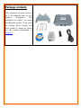
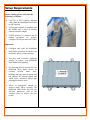
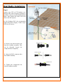
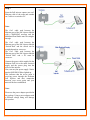
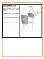
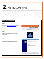
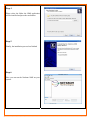
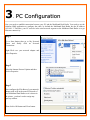
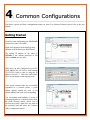
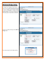
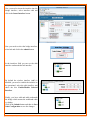
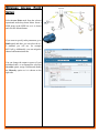
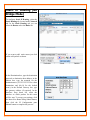
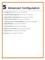
Quick Installation Guide
Multiband Dual Radio V3
Package Contents:
•
•
•
•
•
•
Multiband Dual Radio v3
Mounting Bracket (Include: 2 stainless & steel U-Bolt, 1 Bracket and 4 screw nuts)
100-240VAC – 48VDC, 350 mA PoE Injector
Power Cable
RJ45 Waterproof Connector System
CD-ROM
1 Hardware Installation
.
Warnings
•
Do not work on the system or connect or disconnect cables during periods of lightning activity.
•
NETKROM shall not be liable for incidental or consequential damages resulting from the furnishing,
performance, or use of this manual.
•
Do not locate the antenna near overhead power lines or other electric light or power circuits, or where it
can come into contact with such circuits. When installing the antenna, take extreme care not to come
into contact with such circuits, as they may cause serious injury or death.
•
Only trained and qualified personnel should be allowed to install, replace, or service this equipment.
•
To meet regulatory restrictions, the radio and the external antenna must be professionally installed. The
network administrator or other IT professional responsible for installing and configuring the unit must
be a suitable professional installer. Following installation, access to the unit should be password
protected by the network administrator to maintain regulatory compliance.
•
The Multiband Dual Radio and PoE injector can be damaged by incorrect power application. Read and
carefully follow the installation instructions before connecting the system to its power source.
Package contents
Take a moment to ensure you have
all of the following parts in your
Outdoor
Waterproof
Unit
installation kit before you begin
installing the product. If any parts
are missing, please contact your
local vendor or contact us, please
see the contact information in
Section 6.
Setup Requirements
Before starting, please verify that the
following is available:
•
CAT5/5e or FTP Outdoor Ethernet
cable (from the Multiband Dual Radio
to PoE Injector)
•
At least one computer is installed with
the NNMS and a wired or wireless
network interface adapter
•
TCP/IP protocol is installed and IP
address parameters are properly
configured on all your network’s nodes
Important!
•
Configure and verify the Multiband
Dual Radio operations first before you
mount the unit in a remote location.
•
You may need to install a lightning
arrestor to protect your Multiband
Dual Radio from lightning.
•
For choosing the best location for your
Multiband Dual Radio choose an
elevated
location
where
trees,
buildings and large steel structures will
not obstruct the antenna signals and
which offers maximum line-of-sight
propagation with the users.
•
Select an appropriate antenna to
improve range and/or coverage. The
Multiband Dual Radio also lets you
fine-tune parameters such as the
transmit power to achieve the best
results.
Dual Radio Installation
Step 1:
Connect your UTP or FTP Outdoor cat.5
Ethernet cable with waterproof connector to
the RJ-45 connector on the Multiband Dual
Radio. Then connect the other end of the
cable to the PoE injector.
For the Netkrom PoE, the recommended
length of the RJ45 Category 5 cable is up to
260 feet or 80 meters.
1.- Remove the thin enclosure nut
from the feedthru assembly. This
can be discarded. Loosen the
compression nut completely
Enclosure Nut
Feedthru Assembly
2.- Insert the RJ45 connector thru
the feedthru assembly
Compression Nut
3.- Tighten the compression nut
loosely feedthru assembly
4.- Screw the entire feedthru assembly into the RJ45ECS housing which is already mounted in the
enclosure. There should be a rubber gasket between
the two assemblies. Tighten the feedthru assembly to
create a seal.
5.- The final step is to tighten the compression nut
until the gaskets are tight around the Cat5 cable.
Always push the cable toward the connector while
tightening to ensure good strain relief of cable to
connector.
Step 2:
Connect the external antenna to the N Female
connector of the Multiband Dual Radio.
Screw in the Coaxial cable connector correctly into
the antenna connector (N-Female) located on the
MB-ROMB case.
Make sure the former line is properly done and cover
the N connectors with an insulating tape.
RJ-45 ECS Housing
Step 3
From the PoE injector connect one cat.5
Ethernet cable to the radio and another
cat.5 cable to a switch or PC.
Note:
The Cat.5 cable used between the
Ethernet port of the PoE injector labeled
with a WARNING message and the
Multiband Dual Radio must be straightthrough.
The Cat.5 cable used between the
Ethernet port of the PoE injector labeled
“Switch Hub” and the switch can be
straight-through or crossover.
The Cat.5 cable used between the
Ethernet port of the PoE injector labeled
“Switch Hub” and a PC must be
crossover.
.
Connect the power cable supplied in the
Netkrom PoE kit to the main electrical
supply and the power plug into the
socket of the injector.
Now, turn on your power supply. Notice
that the POWER LED has lighted up.
This indicates that the access point is
receiving power through the Netkrom
PoE Injector and that connection
between your access point and your
network has been established.
Note:
Please use the power adapter provided in
the package. Using a power adapter with
a different voltage rating will damage
this product.
Mounting Dual Radio
Multiband Dual Radio v3 device can be
mounted on the pole or tower as shown in
following:
1. - Mount the bracket to the pole with the Ubolts.
2. - Attach the radio to the bracket which was
mounted on the pole with the supplied nuts and
U-bolts.
3. - Tighten the U-bolts and nuts with hand
tools.
2 NETKROM NMS
.
NETKROM Network Management System (NMS) is a java based graphical user interface application, running
on any operating system, providing ability to manage the wireless device remotely over the IP network.
Its main purpose is to serve as a network tool for administrating and monitoring the wireless device. The NMS
allows the user to setup all important hardware and software parameters of the device according to the user's
requirements. Moreover, it has the ability to display information for data flow, device status, and event logging.
Installing The NMS
Step 1
Please visit http://www.netkrom.com and click
on tab Support and click on Download Drivers.
Download the latest version of the Netkrom
Network Manager.
Step 2
After the download is completed, run the
NMS installer.
Step 3
Follow the wizard installation instructions.
Step 4
Please select the folder the NMS application
will be installed and press the next button.
Step 5
Finally, the installation process has finished
Step 6
Now you can run the Netkrom NMS on your
system.
.
3 PC Configuration
.
Now you need to establish connection between your PC and the Multiband Dual Radio. You need to use the
Netkrom NMS application to configure the radio, by default the Multiband Dual Radio has the IP address
192.168.1.3. Therefore, your PC must be in the same network segment as the Multiband Dual Radio is to get
Ethernet connectivity.
Step 1
Go to Start button then go to My Network
Places and finally click on Network
Connections.
Right-Click over your network adapter and
select Properties.
Step 2
Select the Internet Protocol Option and then
click in Properties.
Step 3
Now configure the IP Address of your network
adapter with an IP in the same IP Network of
your Multiband Dual Radios as it is shown in
the picture, you don’t need to assign any
gateway address.
Then click in OK button and Close button.
4 Common Configurations
.
Find below typical and basic configurations using our units. For advanced features please refer to the user
manual.
Getting Started
In order to start configuring your MB-ROMB
you need to create a new node:
Right click anywhere in the topology map,
and then click the Insert new node button.
The default IP address of the radio is:
192.168.1.3, the default password of the
radio is: admin, use any alias.
Make sure you have configured in your PC
an IP address like 192.168.1.x with netmask
255.255.255.0 and be able to ping the IP
address 192.168.1.3. Click the Add button.
The icon will appear in the topology map.
If the newly inserted node has successfully
responded to a network probe, a green
outline appears around the icon. A red
outline indicates the node is not responding.
You can manage and configure a variety of
operating parameters of network nodes from
the Node Shortcut Menu, which can be
accessed by giving a right click any node in
the topology map and select the Advance
Node Configuration option.
Wireless Bridge Setup
By default the Multiband Dual Radio is a
router, if you want the Multiband Dual Radio
to work as bridge please read this chapter.
As soon as you manage to connect to your
Multiband Radio you can start configuring it.
Check the picture of the NMS user interface.
Create a new bridge clicking in the Add new
bridge button.
Now assign a name for the bridge interface.
Now you need to insert the interface into the
Bridge interface, select interface eth0 and
click in the Insert Interface button.
Now you need to select the bridge interface,
select br0 and click in the submit button.
.
In the interfaces field you can see the eth0
interface underneath the br0 interface.
By default the wireless interface (ath0) is
disabled, you need to enable the interface to
be operational, select the ath0 interface and
check the box Enable/Disable Selected
Interface.
Finally, you have eth0 and ath0 underneath
the bridge which means the multiband radio
is a bridge.
Click in the Submit button and then in Save
Node Configuration to save the changes.
Wireless Access Point
Setup
Select Access Point mode from the selected
operational mode drop down Menu. Insert a
SSID string in the SSID box as it is shown
and click the Submit button.
If you want to specify radio parameters go to
Radio panel and there you can select the wifi standard you will use, for example
802.11a/b/g. Additionally, you can assign the
channel and transmission rate.
You can change the output tx power of your
multiband radio, we recommend to select the
Override option, assign 24 dBm and disable
the Diversity option as it is shown on the
right side.
In order to take effect the changes made in
the configuration, click on Submit button
and then in save configuration.
In this operation mode, you can connect any
wifi client to the Access Point, CPE, Access
Point Client, Laptops, Wireless VoIP
Phones,etc.
Wireless Point to Point
& Point to Multi-Point
Setup
For this example you need 2 or more
multiband radios or other wifi wireless
devices, if you want a bridge network follow
the Wireless Bridge Setup example and
create the wireless bridges. Configure the 1st
device to operate in Access Point Mode,
please read the previous chapter.
Configure the client device to operate in
Access Point Client Mode or Station
Mode and perform a Site Survey.
Select AP Client from the Selected
Operational Mode Drop Down Menu.
Click the Site Survey button
Connect with the desired Access Point.
Select the desired ESSID from the Site
Survey Pop-up Menu.
Click the Connect button
As soon as the devices get connected, the
connection status bar informs you about the
link quality and the Signal Level.
Static IP Routing (No
Bridge Mode)
To configure Static IP Routing, select the
Static Routing tab, located under Network
tab. In the Static Routing tab you can
select the Routes tab or the Rules tab.
If you want to add static routes just click
on the add symbol as shown.
In the Destination box, type the destination
network or destination host address, in the
Subnet box, type the netmask for the
destination net. (255.255.255.255 for a host
destination and 0.0.0.0 for the default
route), in the Default Gateway box, type
the gateway address (if required), In the
Interface drop down list, select the
interface to which packets for this route
will be sent. To accept your settings, click
the Insert New Route dialog Submit button,
then click the IP Configuration pane
Submit button to complete the process.
5 Advanced Configuration
.
1. – Configuring VLANs: Please go to page 43 of User Manual.
2. - Advanced Routing Configuration: Please go to page 46 of User Manual.
3. - Advanced Wireless Configuration: Please go to page 64 of User Manual.
4. - Wireless Security Settings: Please go to page 67 of User Manual.
5. - Configuring Atheros Advanced Capabilities: Please go to page 71 of User Manual.
6. - Dynamic Routing: Please go to page 78 of User Manual.
7. - Firewall and NAT: Please go to page 82 of User Manual.
8. - DHCP Server, Client, Relay: Please go to page 96 of User Manual.
9. - Quality of Service: Please go to page 108 of User Manual.
10. - Hotspot: Please go to page 130 of User Manual.
6 Congratulations
.
With these basics steps you can enjoy your wireless link without problems, please for more information about
the capabilities and advance configuration of our product please see the user manual.
Contact Information
Address:
2134 NW 99th Avenue, Miami FL 33172
Phones:
(+1) 305-418-2232
Fax:
(+1) 305-418-9266
Sales and ordering:
American Customers: [email protected]
Worldwide Customers: [email protected]
Latin American and Spanish Customers: [email protected]
Technical Support :
Worldwide and English Customers: [email protected]
Latin American Customers: [email protected]