1
USER’S MANUAL
Revision: 0
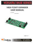
VB2X-TCDOT THERMOCOUPLE
EXPANDER /OUTPUT BOARD
Covered Models:
VB2X-4K4DOT
Divelbiss Corporation
9778 Mt. Gilead Road,
Fredericktown, Ohio 43019
Toll Free: 1-800-245-2327
Web: http://www.divelbiss.com
Email: [email protected]
2014002.0
Table of Contents
Manual Contents
Getting Started
How to Use this Manual........................................................................ 3
Install the VB2X-TCDOT Expander on the VB-2XXX Controller.............. 4
Configuring the VB2X-TC in EZ LADDER Toolkit...................................... 5
Getting to Know the VB2X-TCDOT......................................................... 7
Additional Thermocouple Types............................................................ 7
VB2X-TCDOT Features
Thermocouple Inputs............................................................................ 9
Digital Outputs..................................................................................... 10
PWM Outputs...................................................................................... 11
VB2X-TCDOT Specifications................................................................. 13
WARNING!!
The VB-2XXX with the VB2X-TCDOT installed, as with other programmable controllers must
not be used alone in applications which could be hazardous to personnel in the event of
failure of this device. Precautions must be taken by the user to provide mechanical and/or
electrical safeguards external to this device. This device is NOT APPROVED for domestic or
human medical use.
VB2X-TCDOT Expander User Manual
Document #: 2014002.0.pdf
Divelbiss Corporation • 9778 Mt. Gilead Road • Fredericktown, Ohio 43019 • 1-800-245-2327 • www.divelbiss.com
PAGE 1 of 13
Getting Started
This section explains how to read this manual and understand the symbols and information that it contains.
To begin using your VB2X-TCDOT Expander, you will need to follow these steps:
• Install the VB2X-TCDOT on the VB-2XXX Controller
• Configure the VB-2XXX Controller to use the VB2X-TCDOT in the EZ LADDER Toolkit Project Settings.
Refer to the appropriate sections of this manual for details on the above items.
Getting Started
How to Use this Manual
In this manual, the following conventions are used to distinguish elements of text:
BOLD
italic
SMALL CAPS
Denotes labeling, commands, and literal portions of syntax that must appear exactly as shown.
Used for variables and placeholders that represent the type of text to be entered by the user.
Used to show key sequences or actual buttons, such as OK, where the user clicks the OK button.
In addition, the following symbols appear periodically in the left margin to call the readers attention to specific details in the text:
Warns the reader of a potential danger or hazard associated with certain actions.
Appears when the text contains a tip that is especially useful.
Indicates the text contains information to which the reader should pay particularly close
attention.
All Specifications and Information Subject to Change without Notice
VB2X-TCDOT Expander User Manual
Document #: 2014002.0.pdf
Divelbiss Corporation • 9778 Mt. Gilead Road • Fredericktown, Ohio 43019 • 1-800-245-2327 • www.divelbiss.com
PAGE 3 of 13
Getting Started
Install the VB2X-TCDOT Expander on the VB-2XXX Controller
The VB-2XXX and VB2X-TCDOT are purchased separately. Before the VB2X-TCDOT may be used, it must be installed as the expansion option on the VB-2XXX controller. You will need full access to the VB-2XXX top and bottom. It is recommended to disconnect and un-mount the VB-2XXX prior to beginning this installation.
To Install the VB2X-TCDOT (example: VB2X-4K4DOT)
1. Un-mount and disconnect the VB-2XXX Controller
2. Using the 4 metal spacers and 4 of the screws provided, install the spacers on the VB-2XXX controller in the provided expansion
holes as shown in Figure 1-1. The male side (threaded post) of the spacer will go through the VB-2XXX board from the top to
bottom. Install 4 Lock washer and 4 nuts to the spacers (on the back side).
IN0 IN1 IN2 IN3 IN4 IN5 CA +VO
IOT VOT
ISPAN
ADJ
TX RX
IN6 IN7 IN8 IN9 IN10 IN11 CB +VO
IN0
IN1
IN2
IN3
IN4
IN5
VSPAN
ADJ
TX+ TX-
MICRO SD
CARD
SOCKET
CAN
PORT
IN6
IN7
IN8
IN9
IN10
IN11
1
ON
2
SW4
SW5
6
7
8
AN5 AN6 AN7
.
3
H L +V
1
ON
2
3
4
5
OT0
OT1
OT2
OT3
OT4
OT5
OT6
OT7
OT7 OT6 OT5 OT4 +VB OT3 OT2 OT1 OT0 +VA
VB2X Expander
Mounting Holes.
Install Spacers in
these locations.
AN0 AN1AN2 AN4
SW2
BATT
ENABLE
R330
DISPLAY
DISP
CONTRAST
SW3
SW5
3
SW6
1
2
3
ON
+VO CTA CTB CTC
D42
D41
D40
I2
I1
SW1
2
ON
1
ETHERNET
PORT
+VO
KEYPAD
STAT WD
EXP CONNECTOR
ON
1
2
3
4
5
6
7
8
VB-2XXX
+VIN +VO
Mount Spacers on
Component Side
x4
VB-2XXX
Install 4 Nuts with
Lockwashers on
solder side
Figure 1-1 - Installation of Spacers
VB2X-TCDOT Expander User Manual
Document #: 2014002.0.pdf
Divelbiss Corporation • 9778 Mt. Gilead Road • Fredericktown, Ohio 43019 • 1-800-245-2327 • www.divelbiss.com
PAGE 4 of 13
Getting Started
3. Carefully aligning the VB2X-TCDOT with the installed spacers, gently plug the VB2X-TCDOT into the EXP connector on the
VB-2XXX. Ensure proper alignment on EXP. When installed correctly, all the VB2X-TCDOT pins will be plugged into the EXP
connector and the VB2X-TCDOT will be placed against the spacers and the mounting holes will align with the spacers correctly.
Refer to Figure 1-2.
4. Install the remaining 4 screws and lockwashers provided to secure the VB2X-TCDOT to the VB-2XXX controller (installed spacers).
Install 4 Screws to
Secure VB2X Expander
Align Connector with
Connector on VB-2XXX
Align Mounting Holes
with Spacers
Terminal Blocks
removed for clarity
IN0 IN1 IN2 IN3 IN4 IN5 CA +VO
IOT VOT
ISPAN
ADJ
TX RX
IN6 IN7 IN8 IN9 IN10 IN11 CB +VO
IN0
IN1
IN2
IN3
IN4
IN5
MICRO SD
CARD
SOCKET
VSPAN
ADJ
TX+ TX-
OT7 OT6 OT5 OT4 +VB OT3 OT2 OT1 OT0 +VA
CAN
PORT
.
AN5 AN6 AN7
EXP
+
+
-
R330
AN0 AN1 AN2 AN4
+
+VA OT0 OT1 OT2 OT3
-
+
IN6
IN7
IN8
IN9
IN10
IN11
H L +V
OT0
OT1
OT2
OT3
OT4
OT5
OT6
OT7
DISPLAY
Top View after
installation of
VB2X-TCDOT
DISP
CONTRAST
3
SW5
2
3
1
2
ON
1
ON
D42
D41
D40
I2
I1
SW1
+VO CTA CTB CTC
ETHERNET
PORT
+VO
KEYPAD
STAT WD
ON
1
2
3
4
5
6
7
8
+VIN +VO
Figure 1-2 - Mounting the VB2X-TCDOT
Configuring the VB2X-TC in EZ LADDER Toolkit
It is assumed that you are familiar with the VB-2XXX before installing this expansion option. Please refer to the VB-2XXX User
Manual for details regarding the VB-2XXX.
Before you can begin using features on the VB2X-TCDOT, it must be configured as an option for the VB-2XXX target within the EZ
LADDER Toolkit. For help with installing or using EZ LADDER, please refer to the P-Series EZ LADDER Toolkit Manual.
1. In EZ LADDER, from the File Menu at the top, click PROJECT then SETTINGS. This will open the Project Settings Window.
Select VB-2000 as the target from the choices. Refer to Figure 1-3.
VB2X-TCDOT Expander User Manual
Document #: 2014002.0.pdf
Divelbiss Corporation • 9778 Mt. Gilead Road • Fredericktown, Ohio 43019 • 1-800-245-2327 • www.divelbiss.com
PAGE 5 of 13
Getting Started
Figure 1-3 - Project Settings Window
2. Click the PROPERTIES button to the right side of the window. The VB-2000 Properties Window will open. Make sure the
proper model is selected in the drop-down menu. If any expansion board was installed previously, it would be listed in
the Expansion Pane.
3. Highlight the I/O Expansion in the list and click the PROPERTIES button on the right side of the Expansion pane in
the VB-2000 Properties Window. The I/O Expansion Properties Window will open. Refer to Figure 1-4.
4. Select the VB2X-4K4DOT expansion board from the list of Expansion boards. Refer to Figure 1-4. The Details section of the
window will update with the devices supported on the expander (for reference only) that will be installed in the project
settings of the program.
Figure 1-4 - I/O Expansion Properties
5. Click OK to accept the VB2X-4K4DOT and close the I/O Expansion Properties Window.
6. Click OK to close the VB-2000 Properties window. Click OK to close the Project Settings window.
7. Save your ladder diagram using the menu FILE and SAVE or SAVE AS to save the current settings in your program.
The VB2X-4K4DOT expander is now installed. The real variables TC1-TC4 are automatically created and represent the temperature
of each thermocouple input channel (1-4) in degrees C. The four output boolean variables EXP_OT0 - EXP_OT3 are automatically
created.
VB2X-TCDOT Expander User Manual
Document #: 2014002.0.pdf
Divelbiss Corporation • 9778 Mt. Gilead Road • Fredericktown, Ohio 43019 • 1-800-245-2327 • www.divelbiss.com
PAGE 6 of 13
Getting Started
Getting to Know the VB2X-TCDOT
The VB2X-TCDOT is an expander for the VB-2XXX controller. The VBEX-TCDOT provides up to 4 Thermocouple inputs and 4 Digital
Sourcing Outputs. The following models are supported as VB2X-TCDOT expanders. See Figure 1-5.
+
Model #
Description
VB2X-4K4DOT: VB2X-TCDOT expander with 4 Type K Thermocouples, 4 Sourcing Digital Outputs
+VA OT0 OT1 OT2 OT3
TC2
+
EXP
- +
TC3
- +
-
TC4
-
TC1
Thermocouple Input
Digital Output
Digital Output
Terminals (+-)
Terminals
Power Terminal
Figure 1-5 - VB2X-TCDOT Features
Additional Thermocouple Types
Other thermocouple types, (J, N, R, S) are available upon request. Please consult the factory for availability of VB2X expansion with
these thermocouple types.
VB2X-TCDOT Expander User Manual
Document #: 2014002.0.pdf
Divelbiss Corporation • 9778 Mt. Gilead Road • Fredericktown, Ohio 43019 • 1-800-245-2327 • www.divelbiss.com
PAGE 7 of 13
VB2X-TCDOT Features
This section explains the VB2X-TCDOT Expander hardware features, options and information regarding EZ LADDER Toolkit for basic
operation.
VB2X-TCDOT Features
Thermocouple Inputs
The VB2X-TC provides up to 4 Thermocouples. The type and quantity of each thermocouple input is based on the actual Model Number of the Expander ordered.
Model #
Description
VB2X-4K4DOT: VBEX-TCDOT expander with 4 Type K Thermocouples
Each thermcouple input is represented in the EZ LADDER Toolkit ladder diagram using (Real) variables labeled TC1 - TC4. These variables were created automatically when the VB2X-TCDOT expander was configured as the expansion option for the VB-2XXX target.
Each variable (TC1- TC4) will represent the actual temperature read by the connected thermocouple in degrees Celsius. If you wish to have temperatures in degrees Fahrenheit, you must convert the values using mathematical function blocks in your ladder diagram program. Each thermocouple channel internally has all the required cold-junction
compensation and linearization required.
Thermocouple Input Connections
For each of the thermocouple inputs (TC1-TC4), a + and - terminal are provided. Refer to Figure 1.5 for locations of the thermocouple input terminals and their polarity. Figure 2-1 illustrates a typical thermocouple connection.
When connecting thermocouples, connect the thermocouple wire directly to the terminals provided. When mounted in
an enclosure, ensure that only thermocouple wire of the appropriate type is used for the connections between the VBEX-
TC thermocouple terminals and the actual enclosure entry. Failure to use the proper thermocouple wire will result in
incorrect temperature readings.
Thermocouple Connections
- +
TC1
+
Extension
Wires
-
Thermocouple
Measuring Junction
Connection
Head
Figure 2-1 - Typical Thermocouple Input Connection
The operating temperature range of the expander may vary based on model number. The VB-2XXX is rated for -40°C to +80°C, but some expanders may not operate under this full range. The controller and expander should only be installed where the temperature range of the narrowest window between the controller and the expander is sufficient.
VB2X-TCDOT Expander User Manual
Document #: 2014002.0.pdf
Divelbiss Corporation • 9778 Mt. Gilead Road • Fredericktown, Ohio 43019 • 1-800-245-2327 • www.divelbiss.com
PAGE 9 of 13
VB2X-TCDOT Features
Digital Outputs
The VB2X-TCDOT includes 4 on-board digital outputs. They are identified in the EZ LADDER Toolkit and this manual as EXP_OT0 EXP_OT3 (on the expander as OT0 - OT3) and these variables are automatically created when the VB2X-TCDOT is selected as the
VB-2XXX Expansion. These outputs are sourcing, therefore an energized output will source an output voltage equal to the controller
input voltage. Refer to Figure 2-2 for typical output connections.
An external power connection and source is required to supply power for the outputs. Power is supplied by the +VA
terminal using the 18 AWG wire or larger. The +VA terminal and expander outputs allow for expander output loads to be controlled at different voltages from the controller I/O. The expander outputs will operate at any voltage from 8-32VDC.
The Expander outputs and controller outputs may be connected to different voltages, but the power supplies connected must have the same common (ground). Failure to use the same common for the expander outputs, controller outputs and controller power may cause unwanted operation and may cause damage to the VB-2XXX.
Each output can drive a load up to maximum current rating listed in the specifications section (resistive) and includes an automatic
over-current shutdown safety. In the event an over current condition exists, the output will shut down. This shut down condition is
reset when the output is turned off (set to false) in the ladder diagram.
Each output requires a minimum load to operate correctly. Depending upon the device connected to an output, a
minimum load resistor may be required. If the output is ON or true regardless of the ladder diagram program, connect a 470Ω to 1KΩ load from the output to input power common.
To control a digital output in a ladder diagram, place and connect the appropriate coil for your needs. The DIRECT COIL and INVERTED COIL functions are used to control digital outputs in the ladder diagram. When placing the coil, verify you select the correct output address (EXP_OT0 - EXP_OT3) from the provided drop-down menu.
Digital / PWM Output Connections
LOAD
LOAD
LOAD
LOAD
OT0 OT1 OT2 OT3 +VA
+8-32 VDC
Same Load Common must be used for both the
VB-2XXX controller, VB-2XXX Outputs and the
VB2X-TCDOT Expander Outputs.
Figure 2-2 - Typical Digital / PWM Output Connections
Each expander output will may be operated as a digital on/off output or as a pulse width modulated (PWM) output. To operate one or more digital outputs as PWM output, it must must be configured in the EZ LADDER Toolkit Project Settings.
VB2X-TCDOT Expander User Manual
Document #: 2014002.0.pdf
Divelbiss Corporation • 9778 Mt. Gilead Road • Fredericktown, Ohio 43019 • 1-800-245-2327 • www.divelbiss.com
PAGE 10 of 13
VB2X-TCDOT Features
PWM Outputs
The VB2X-TCDOT’s 4 digital outputs may also be used as Pulse Width Modulation (PWM) outputs instead of digital (on/off) outputs.
The outputs whether used as digital on/off outputs or PWM outputs connect to loads the same and will only operate at the specifications listed in the Specifications section of this manual. Refer to Figure 2-2 for connections.
By default, the PWM functionality is not enabled (as it is enabled for digital on/off output functionality). Each output may only be
used as either a digital output (on/off) or PWM. Outputs to be used as PWM channels must be configured in EZ LADDER Toolkit using the Project Settings Menu.
The following are the PWM channel assignments for the digital output channels OT0 - OT3 (as listed on the expander in silkscreen).
VB2X-TCDOT Terminal Labeling
PWM Channel
Digital Output Channel / EZ LADDER Variable
OT0
PWM4
EXP_OT0
OT1
PWM5
EXP_OT1
OT2
PWM10
EXP_OT2
OT3
PWM11
EXP_OT3
It is assumed that you are familiar with the VB-2XXX before installing PWM. Please refer to the VB-2XXX User Manual for details
regarding the VB-2XXX. Refer to the P-Series EZ LADDER Toolkit Manual for more details on configuring PWM and other options in
EZ LADDER Toolkit.
1. In EZ LADDER, from the File Menu at the top, click PROJECT then SETTINGS. This will open the Project Settings Window.
Select VB-2000 as the target from the choices. Refer to Figure 2-3.
Figure 2-3 - Project Settings Window
2. Click the PROPERTIES button to the right side of the window. The VB-2000 Properties Window will open. Make sure the
proper model is selected in the drop-down menu. The VB2X-4K4DOT should already be installed prior to configuring the
PWM channels.
3. If PWM is listed under the Internal heading, then PWM has been installed (for outputs on the VB-2XXX controller). Only the
VB2X-4K4DOT PWM channels need to be configured. If PWM is listed under Internal, highlight (select) it and click
PROPERTIES, othewise, click the ADD DEVICE button. Refer to Figure 2-4.
4. The PWM Properties window will open. Refer to Figure 2-5. The channels listed were previously configured. To add additional
channels, click the ADD button. The Add PWM Dialog will open. Refer to Figure 2-6.
VB2X-TCDOT Expander User Manual
Document #: 2014002.0.pdf
Divelbiss Corporation • 9778 Mt. Gilead Road • Fredericktown, Ohio 43019 • 1-800-245-2327 • www.divelbiss.com
PAGE 11 of 13
VB2X-TCDOT Features
Figure 2-4 - VB-2XXX Properties
Figure 2-5 - PWM Properties
5. Click to highlight the channels need to add. Refer to the list of PWM channels supported on the VB2X-4K4DOT listed earlier in
this section. Holding the CTRL key while clicking on PWM channels will allow multiiple selections. Click OK to accept the
selected PWM channels.
6. Enter the base PWM frequency for the channel groups as needed (channels 0-5 use one frequency while channels 6-11 use
another frequency setting. PWM channels in each group are based on the frequency for each group. The frequencies may be
the same, but the frequency must be entered in both boxes. Refer to Figure 2-5.
7. Click OK to close the PWM Properties window. Click OK to close the VB-2000 Properties window. Click OK to close the Project
Settings window.
8. Save your ladder diagram using the menu FILE and SAVE or SAVE AS to save the current settings in your program.
The VB2X-4K4DOT PWM channel(s) are now installed. The channels may be used in the ladder diagram by the PWM and PWM_
FREQ function blocks.
Figure 2-6 - Add PWM Channels
VB2X-TCDOT Expander User Manual
Document #: 2014002.0.pdf
Divelbiss Corporation • 9778 Mt. Gilead Road • Fredericktown, Ohio 43019 • 1-800-245-2327 • www.divelbiss.com
PAGE 12 of 13
VB2X-TCDOT Features
VB2X-TCDOT Specifications
Type K Thermocouple Inputs:
Qty up to 4
Measurement Range: -270oC to 1372°C
Resolution: 14 Bit, 0.25°C per bit
Accuracy -200°C to +700°C: +/- 2°C (Ambient -20oC to 80oC)
Accuracy +700°C to +1350°C: +/- 4°C (Ambient -20oC to 80oC)
Accuracy - 270°C to +1372°C: +/- 6°C (Ambient -40oC to 80oC)
Digital I/O:
4 Digital Outputs on-board
Outputs rated 2A Max per output, Over-current protected.
LED Indicators
Sourcing as Group of 4 Outputs, External Power Source Required on +VA, 8-32VDC
Operating Temp:
-40°C to 80°C
Dimensions:
2.9” Wide x 6.4” Length x .1.35” Tall.
Mounting:
Installs on VB-2XXX Controller, Stack Mount using #6 spacers and screws
Type:
Open Board
Storage Temperature:
-40 to 85°C
VB2X-TCDOT Expander User Manual
Document #: 2014002.0.pdf
Divelbiss Corporation • 9778 Mt. Gilead Road • Fredericktown, Ohio 43019 • 1-800-245-2327 • www.divelbiss.com
PAGE 13 of 13