1
CC-Link IE Controller Network Interface Board
User's Manual (For SW1DNC-MNETG-B)
-Q80BD-J71GP21-SX
-Q80BD-J71GP21S-SX
-Q81BD-J71GP21-SX
-Q81BD-J71GP21S-SX
SAFETY PRECAUTIONS
(Be sure to read these instructions before using the product.)
Before using this product, read this manual and the relevant manuals introduced in this manual carefully
and handle the product correctly with full attention to safety.
Note that these precautions apply only to this product. Refer to the user's manual of your CPU module for
safety precautions on programmable controller systems.
In this manual, the safety instructions are ranked as "
WARNING" and "
CAUTION".
WARNING
Indicates that incorrect handling may cause hazardous conditions,
resulting in death or severe injury.
CAUTION
Indicates that incorrect handling may cause hazardous conditions,
resulting in minor or moderate injury or property damage.
Note that failure to observe the
circumstances.
CAUTION level instructions may also lead to serious results depending on the
Be sure to observe the instructions of both levels to ensure personal safety.
Please store this manual in a safe place for future reference. This manual must be forwarded to the end user.
A-1
[Design Precautions]
WARNING
Configure safety circuits external to the programmable controller to ensure that the entire system
operates safely even when a fault occurs in a personal computer. Failure to do so may result in an
accident due to an incorrect output or malfunction.
(1) Emergency stop circuits, protection circuits, and protective interlock circuits for conflicting
operations (such as forward/reverse rotations or upper/lower limit positioning) must be
configured external to the programmable controller.
(2) The station to which the board is installed may be disconnected from the data link due to a data
link error. If this occurs, the data output from the station and written to other stations before the
error will be held until the station is reconnected to the network (until its data link is restarted).
Provide a mechanism for data link status monitoring and error handling for each station that is
connected to the data link system.
For the operating status of each station after a communication failure, refer to CC-Link IE Controller
Network Reference Manual for each network. Incorrect output or malfunction due to a
communication failure may result in an accident.
When changing data during operation, configure an interlock circuit in the program to ensure that the
entire system will always operate safely. Configure an interlock circuit in the program, and determine
corrective actions to be taken between the external device and CPU module in case of a
communication failure.
Laser diodes are used in the optical transceivers of the CC-Link IE Controller Network. The laser
class (IEC 60825-1) of these laser diodes is Class 1. Do not look directly at laser light. Doing so may
harm your eyes.
CAUTION
Do not install the external power supply or communication cables together with the main circuit lines
or power cables. Keep a distance of 100mm (3.94 in.) or more between them. Failure to do so may
result in malfunction due to noise.
[Installation Precautions]
WARNING
Shut off the external power supply for the system in all phases before installing the board to or
removing it from the personal computer.
Failure to do so may result in electric shock or cause the board to fail or malfunction.
Do not touch any connectors while power is on. Doing so may cause electric shock or malfunction.
A-2
CAUTION
Use the board in an environment that meets the general specifications in this manual.
Failure to do so may result in electric shock, fire, malfunction, or damage to or deterioration of the
product.
Do not directly touch any conductive parts and electronic components of the board.
Doing so may cause malfunction or failure of the board.
When installing the board, take care not to get injured by an implemented component or a
surrounding member.
Fix the board by tighten the board-fixing screws within the specified torque range.
Undertightening may cause drop of the component or wire, short circuit, or malfunction.
Overtightening may damage the screw and/or module, resulting in drop, short circuit, or malfunction.
For the tightening torque of the board-fixing screws, refer to the manual supplied with the personal
computer.
Before handling the board, touch a conducting object such as a grounded metal to discharge the static
electricity from the human body.
Failure to do so may cause the board to fail or malfunction.
Install the board to a personal computer which is compliant with PCI standard or PCI Express®
standard (Section 2.5 Operating Environment). Failure to do so may cause a failure or
malfunction.
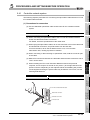
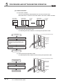
Securely insert the board into the PCI slot following the board installation instruction of the personal
computer.
Incorrect insertion of the board may lead to a malfunction, failure or drop of the board.
When installing the board, take care not to get injured by an implemented component or a
surrounding member.
When installing the board, take care not to contact with other boards.
Handle the board in a place where static electricity will not be generated.
Failure to do so may cause a failure or malfunction.
The board is included in an antistatic envelope.
When storing or transporting it, be sure to put it in the antistatic envelope.
Failure to do so may cause a failure or malfunction.
Do not drop or apply a strong impact to the board.
Doing so may cause a failure or malfunction.
A-3
[Wiring Precautions]
WARNING
Shut off the external power supply for the system in all phases before installing the board or starting
wiring.
Failure to do so may result in electric shock, damage to the product, or malfunction.
After installation of the board and wiring, attach the cover on the module before turning it on for
operation.
Failure to do so may result in electric shock.
CAUTION
Check the rated voltage and pin-out before wiring to the external power supply cable, and connect
the cables correctly.
Connecting a power supply with a different voltage rating or incorrect wiring may cause a fire or
failure.
Place the communication cable and the external power supply cable connected to the board in a
duct or clamp them.
If not, dangling cables may swing or inadvertently be pulled, resulting in damage to the board or
cables or malfunctions due to poor contact.
When disconnecting the cable from the board, do not pull the cable by the cable part.
Pulling the cable connected to the board may result in malfunction or damage to the board or cable.
Prevent foreign matter such as dust or wire chips from entering the personal computer.
Such foreign matter may cause a fire, failure, or malfunction.
Do not install the external power supply or communication cables together with the main circuit lines
or power cables.
Keep a distance of 100mm (3.94 in.) or more between them. Failure to do so may result in
malfunction due to noise.
Special skills and tools are required to connect the communication cable to the connector plug,
which is an exclusive product.
When purchasing it, please consult your local Mitsubishi representative.
Incomplete connection can result in a short, fire or malfunction.
Securely plug the communication cable to the connector of the board.
Then, check for any incomplete connection.
Poor contact may cause an erroneous input or output.
A-4
[Wiring Precautions]
CAUTION
Use a specified tool for crimping of the cable and contacting pin. Imperfect crimping may cause a
malfunction.
Verify the pin-out and fully insert the crimped contacting pin into the connector. Imperfect insertion
may cause a failure or malfunction.
Insert the wired external power supply cable into the external power supply cable connector until a
click is heard.
Imperfect insertion may cause a failure or malfunction.
Always ground the personal computer to the protective ground conductor.
Failure to do so may cause a malfunction.
[Startup/Maintenance Precautions]
WARNING
Shut off all phases of the external power supply before cleaning the board or retightening the fixing
screws. Failure to do so may result in an electric shock, or cause a failure or malfunction of the
board.
Shut off the external power supply for the system in all phases before installing the board to or
removing it from the personal computer.
Failure to do so may result in electric shock or cause the board to fail or malfunction.
Do not connect or disconnect any communication cable while power is on.
Doing so may result in a malfunction.
A-5
[Startup/Maintenance Precautions]
CAUTION
Thoroughly read the manual and ensure the safety before performing program modification during
operation, forced output, operation such as RUN, STOP and PAUSE.
An improper operation will result in mechanical damage or accidents.
Do not disassemble or modify the board.
Doing so may cause failure, malfunction, injury, or a fire.
Fix the board by tighten the board-fixing screws within the specified torque range. Undertightening
may cause drop of the component or wire, short circuit, or malfunction. Overtightening may damage
the screw and/or module, resulting in drop, short circuit, or malfunction.
For the tightening torque of the board-fixing screws, refer to the manual supplied with the personal
computer.
Before handling the board, touch a conducting object such as a grounded metal to discharge the
static electricity from the human body.
Failure to do so may cause the board to fail or malfunction.
The board is included in an antistatic envelope.
When storing or transporting it, be sure to put it in the antistatic envelope.
Failure to do so may cause a failure or malfunction.
The microprocessor built in the board will reach a high temperature during operation. Do not touch it
directly when replacing the board.
Doing so may result in a failure, malfunction or injury.
[Disposal Precautions]
CAUTION
When disposing of this product, treat it as industrial waste.
A-6
CONDITIONS OF USE FOR THE PRODUCT
(1) Mitsubishi programmable controller ("the PRODUCT") shall be used in conditions;
i) where any problem, fault or failure occurring in the PRODUCT, if any, shall not lead to any major
or serious accident; and
ii) where the backup and fail-safe function are systematically or automatically provided outside of
the PRODUCT for the case of any problem, fault or failure occurring in the PRODUCT.
(2) The PRODUCT has been designed and manufactured for the purpose of being used in general
industries.
MITSUBISHI SHALL HAVE NO RESPONSIBILITY OR LIABILITY (INCLUDING, BUT NOT
LIMITED TO ANY AND ALL RESPONSIBILITY OR LIABILITY BASED ON CONTRACT,
WARRANTY, TORT, PRODUCT LIABILITY) FOR ANY INJURY OR DEATH TO PERSONS OR
LOSS OR DAMAGE TO PROPERTY CAUSED BY the PRODUCT THAT ARE OPERATED OR
USED IN APPLICATION NOT INTENDED OR EXCLUDED BY INSTRUCTIONS, PRECAUTIONS,
OR WARNING CONTAINED IN MITSUBISHI'S USER, INSTRUCTION AND/OR SAFETY
MANUALS, TECHNICAL BULLETINS AND GUIDELINES FOR the PRODUCT.
("Prohibited Application")
Prohibited Applications include, but not limited to, the use of the PRODUCT in;
• Nuclear Power Plants and any other power plants operated by Power companies, and/or any
other cases in which the public could be affected if any problem or fault occurs in the PRODUCT.
• Railway companies or Public service purposes, and/or any other cases in which establishment of
a special quality assurance system is required by the Purchaser or End User.
• Aircraft or Aerospace, Medical applications, Train equipment, transport equipment such as
Elevator and Escalator, Incineration and Fuel devices, Vehicles, Manned transportation,
Equipment for Recreation and Amusement, and Safety devices, handling of Nuclear or
Hazardous Materials or Chemicals, Mining and Drilling, and/or other applications where there is a
significant risk of injury to the public or property.
Notwithstanding the above, restrictions Mitsubishi may in its sole discretion, authorize use of the
PRODUCT in one or more of the Prohibited Applications, provided that the usage of the PRODUCT
is limited only for the specific applications agreed to by Mitsubishi and provided further that no
special quality assurance or fail-safe, redundant or other safety features which exceed the general
specifications of the PRODUCTs are required. For details, please contact the Mitsubishi
representative in your region.
A-7
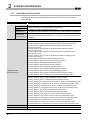
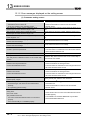
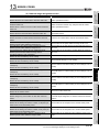
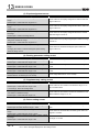
REVISIONS
*The manual number is given on the bottom left of the back cover.
Print Date
APR., 2007
*Manual Number
Revision
SH (NA)-080691ENG-A First edition
Addition
Section 8.1.2, Appendix 3
Correction
Oct., 2007
SH(NA)-080691ENG-B
GENERIC TERMS AND ABBREVIATIONS,
Section 1.2, Section 1.3, Section 2.5, Chapter 5, Section 8.1.1, Section 8.1.3,
Section 8.2, Section 8.3, Section 9.2.1, Section 9.2.3, Section 10.2.1,
Section 10.2.3, Chapter 15, Section 16.2, Section 16.3.1, Appendix 4
Section 8.1.2 changed to Section 8.1.3.
"MELSECNET/G network system" (controller network) is changed to "CC-Link
IE Controller Network"
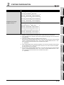
Correction
SAFETY PRECAUTIONS, PRECAUTIONS FOR USE, INTRODUCTION,
CONTENTS, MANUAL, HOW TO USE THIS MANUAL,
GENERIC TERMS AND ABBREVIATIONS, PACKING LIST, CHAPTER 1,
Section 1.1, Section 1.2, Section 1.3, Section 2.1, Section 2.2.2, Section 2.2.3,
Section 2.3, Section 2.3.2, Section 2.4, Section 2.5, Section 2.6, CHAPTER 3,
Section 3.1, Section 3.2, CHAPTER 4, Section 4.1, Section4.2, Section 4.2.1,
Section 5.1, CHAPTER 6, Section 6.1, Section 6.2, Section 6.2.1,
Section 6.2.2, Section 6.3, Section 6.4, Section 6.4.1, Section 6.5,
Section 6.5.1, Section 6.5.2, Section 6.5.3, Section 6.6, Section 6.6.1,
Section 6.6.2, CHAPTER 7, Section 7.1, Section 7.2, Section 7.3,
Section 7.3.3, Section 7.4, Section 7.5, Section 7.6, Section 7.7, Section 7.8,
Jan., 2008
SH(NA)-080691ENG-C
Section 7.9, Section 8.1, Section 8.1.1, Section 8.1.2, Section 8.1.3,
Section 8.2, CHAPTER 9, Section 9.1, Section 9.1.1, Section 9.2,
Section 9.2.1, Section 9.2.2, Section 9.2.3, Section 9.2.4, Section 9.3,
Section 9.3.1, Section 9.3.2, Section9.3.3, Section 9.4, Section 9.4.1,
Section 9.4.6, Section 9.4.7, Section 9.4.8, Section 9.5.1, Section 9.5.3,
Section 9.5.4, Section 10.1.1, Section 10.2.1, Section 10.3, Section 10.4,
Section 10.5, CHAPTER 11, Section 11.1, Section 11.1.2, Section 11.2,
Section 12.1, Section 12.4, Section 12.5, Section 12.6, Section 12.7,
Section 12.8, Section 12.9, Section 13.1.1, Section 13.2, Section 13.2.1,
Section13.3, CHAPTER 14, Section 14.2, Section 14.2.1, Section14.2.2,
Section14.2.3, Section 14.3, CHAPTER 15, Section 16.2, Section 16.3,
Section 16.3.1, Section 16.4, Section 16.4.1, Section16.4.2, Section 16.4.3,
Section 16.4.4, Section 16.4.5, Section 16.4.6, Section 16.5.2, Section 16.5.3,
Section 16.5.4, Section 16.7, APPENDICES
Addition
Section 9.4.7
A-8
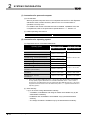
Print Date
*Manual Number
Revision
Addition
Section 9.3.4
May., 2008
SH(NA)-080691ENG-D
Correction
Section 2.5, Section 2.6, Section 6.5.1, Section 6.5.2, Section 6.5.3,
Section 6.6.1, Section 6.6.2, Section 7.1, Section 9.3.3, Section 9.4.1,
Appendix 6.2
Correction
Sep., 2008
SH(NA)-080691ENG-E
Section 2.5, Section 3.2, Section 7.1, Section 9.3.1, Section 9.4.1,
Appendix 6.1
Correction
Oct., 2008
SH(NA)-080691ENG-F
PRECAUTIONS FOR USE, GENERIC TERMS AND ABBREVIATIONS,
Section 2.5, Section 9.4.6, Section 9.4.7, Section 11.1.2
Addition
Section 7.10, Section 9.4.9, Section 16.8
Correction
SAFETY PRECAUTIONS, GENERIC TERMS AND ABBREVIATIONS,
Section 2.2.2, Section 2.3.2, Section 4.2.1, CHAPTER 5, Section 6.5.1,
Apr., 2009
SH (NA)-080691ENG-G
Section 6.5.2, Section 6.5.3, Section 6.6.1, Section 6.6.2, CHAPTER 7,
Section 7.1, Section 7.2, Section 7.5, Section 7.6, Section 7.7, Section 8.1.1,
Section 8.1.3, Section 8.2, Section 8.3, Section 9.1.1, Section 9.2,
Section 9.3.1, Section 9.3.3, Section 9.4.1, Section 9.4.6, Section 11.1.1,
Section 11.1.2, Section 12.2, Section 12.6, Section 12.7, Section 14.3,
CHAPTER 15, Section 16.4.3, Appendix 5.6, Appendix 6.1, Appendix 6.2,
Appendix 6.4
Addition
Section 6.7, Section 14.1.4
Correction
Sep., 2009
PRECAUTIONS FOR USE, Section 4.1, Section 6.1, Section 8.1.3,
SH (NA)-080691ENG-H Section 9.4.5, Section 9.4.6, Section 12.4, Section 13.1.1, Section 14,
Section 15.1, Appendix 2, Index
Deletion
Section 14.1
Section 14.2 and 14.3 are changed to Section14.1 and 14.2.
A-9
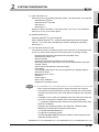
Print Date
*Manual Number
Revision
Addition
CONDITIONS OF USE FOR THE PRODUCT
Correction
SAFETY PRECAUTIONS, MANUAL,
GENERIC TERMS AND ABBREVIATIONS, Section 1.2, Section 2.5,
Section 3.1, Section 3.2, Section 5.1.2, Section 6.2.1, Section 6.2.2,
Section 6.3, Section 6.4, Section 6.4.2, Section 6.5.1, Section 6.5.2,
Section 6.5.3, Section 6.6.1, Section 6.6.2, Section 6.7.1, Section 7.1,
May, 2010
SH(NA)-080691ENG-I
Section 7.2, Section 7.3.1 to 7.3.3, Section 8.1, Section 8.1.1, Section 8.1.3,
Section 8.2, Section 8.3, Section 9.2.1, Section 9.2.3, Section 9.4.1,
Section 9.4.2, Section 9.5.1, Section 10.2.1, Section 10.2.3, Section 11.1.2,
CHAPTER 12, Section 12.3.3, Section 12.3.4, Section 12.9, Section 16.2,
Section 16.4.5, Appendix 3.1, Appendix 3.2
Deletion
Section 12.3.5, Section 12.3.6
Section 1.3 is changed to Appendix 4.
Appendix 4 is changed to Appendix 7.
Jun., 2010
SH(NA)-080691ENG-J
Dec., 2010
SH(NA)-080691ENG-K
A - 10
Correction
Section 2.6
Correction
Section 2.5
Print Date
*Manual Number
Revision
Model addition
Q81BD-J71GP21-SX, Q81BD-J71GP21S-SX
Addition
Appendix 9.3, Appendix 9.4
Correction
SAFETY PRECAUTIONS, PRECAUTIONS FOR USE, INTRODUCTION,
MANUAL, HOW TO USE THIS MANUAL,
GENERIC TERMS AND ABBREVIATIONS, PACKING LIST, CHAPTER 1,
Section 1.1, Section 1.2, Section 2.1, Section 2.4, Section 2.5, Section 3.1,
Section 3.2, Section 5.1.1, Section 6.1, Section 6.2.1, Section 6.3,
Section 6.4.1, Section 6.4.2, Section 6.5.3, Section 6.6.1, Section 6.6.2,
Section 7.9, Section 8.1.1, Section 8.1.2, Section 8.1.3, Section 9.2.1,
Section 9.3.3, Section 9.4.1, Section 9.4.8, Section 10.2.1, Section 10.6,
Jul., 2011
SH(NA)-080691ENG-L
Section 10.7, Section 10.8, Section 10.9, CHAPTER 11, Section 11.2,
Section 12.2, Section 13.1.4, Section 13.2, CHAPTER 14, Section 14.1,
Section 14.2, Section 15.2, Section 15.3, Section 15.3.1, Section 15.4.2,
Section 15.4.4, Section 15.4.5, Section 15.5.1, Section 15.6, Appendix 1,
Appendix 2.1, Appendix 3.1, Appendix 3.4, Appendix 5, Appendix 5.1,
Appendix 5.6, Appendix 7, Appendix 8
Deletion
CHAPTER 11, Section 12.3 to Section 12.9, Section 15.1, Appendix 2.1.1,
Appendix 2.1.2
CHAPTER 12 to 16 are changed to CHAPTER 11 to 15.
Section 2.6 is changed to Appendix 4 and 7. Section 15.2 and 15.3 are
changed to Section 15.1 and 15.2. Appendix 6 is changed to Appendix 3.
Appendix 4 is changed to Appendix 6. Appendix 3 is changed to Appendix 8.
Appendix 7 is changed to Appendix 9.
Jan., 2012
Correction
SH(NA)-080691ENG-M PRECAUTIONS FOR USE, Section 3.1
CHAPTER 5 is changed to Appendix 9, Appendix 9 is changed to Appendix 10
Addition
Mar., 2012
SH(NA)-080691ENG-N
Appendix 11, Appendix 12
Correction
Section 2.5, Section 7.1.1, Section 7.1.3, Section 7.2
Correction
Dec., 2012
SH(NA)-080691ENG-O
SAFETY PRECAUTIONS, GENERIC TERMS AND ABBREVIATIONS,
Section 2.5, Section 3.1, Section 3.2, Section 5.4, Section 7.1.2, Section 11.1.1,
Section 11.3, Section 14.2, Section 14.3
A - 11
Print Date
*Manual Number
Revision
Addition
Section 3.4, Section 5.3.3, Section 5.3.4, Section 8.2.3, Section 14.2.1,
Section 14.2.2, Section 14.3.3, Section 14.7.1, Section 14.7.2, Appendix 7.1,
Appendix 7.2, Appendix 8, Appendix 10.3
Correction
PRECAUTIONS FOR USE, HOW TO USE THIS MANUAL,
GENERIC TERMS AND ABBREVIATIONS, Section 1.2, Section 2.5,
Section 5.1 ~ 5.5, Section 6.7, Section 7.1 ~ 7.3, Section 8.2, Section 8.2.1,
Section 8.2.4, Section 8.3.1, Section 8.4.6, Section 9.2.1, Section 9.2.3,
CHAPTER 10, Section 12.1.4, Section 13.1.2, CHAPTER 14, Section 14.1,
Section 14.2.3, Section 14.3, Section 14.3.2, Section 14.6, Section 14.9,
Sep., 2013
SH(NA)-080691ENG-P
Appendix 5, Appendix 9.1, Appendix 9.2, Appendix 10, Appendix 10.1,
Appendix 10.2, Appendix 11, Appendix 11.2, Appendix 11.3
Section 5.2 is changed to Section 5.3,
Section 5.6.1 and 5.6.2 are changed to Section 5.5.4 and 5.5.5,
Section 5.7.1 is changed to Section 5.5.6,
Section 7.1.1 is changed to Section 7.2,
Section 7.1.3 is changed to Section 14.2.3,
Appendix 4 is changed to Appendix 7,
Appendix 5, 6, 7, 8, 9, 10, 11 and 12 are changed to Appendix 4, 5, 6, 9, 12, 13,
10 and 11
Deletion
Section 5.6, Section 5.7, Section 7.1.2, Section 10.1, Section 10.2,
Section 14.5.4
Correction
Section 2.5, Section 7.1, Section 7.2, Section 8.2.1, Section 8.4.1,
Section 9.1.1, Section 9.2, Section 9.3, Section 9.4, Section 9.6, Section 9.7,
Section 9.9, Section 12.1, Section 14.1, Section 14.2.2, Section 14.2.3,
Jun., 2014
SH(NA)-080691ENG-Q Section 14.3.2, Appendix 3.1, Appendix 7.2, Appendix 9.2, Appendix 10.2,
Appendix 10.3, Appendix 11
Section 9.9 to Section 9.11 are changed to Section 9.8 to Section 9.10
Deletion
Section 9.8
Jan., 2015
SH(NA)-080691ENG-R
Apr., 2015
SH(NA)-080691ENG-S
Sep., 2015
SH(NA)-080691ENG-T
Correction
Section 3.2, Section 8.3.4
Correction
Section 2.5, Section 7.2, Section 9.3, Section 9.4, Section 14.3.2
Correction
Section 2.5, Section 7.1, Section 14.2.3, Appendix 8
Japanese Manual Version SH-080690-T
This manual confers no industrial property rights or any rights of any other kind, nor does it confer any patent licenses.
Mitsubishi Electric Corporation cannot be held responsible for any problems involving industrial property rights which may
occur as a result of using the contents noted in this manual.
© 2007 MITSUBISHI ELECTRIC CORPORATION
A - 12
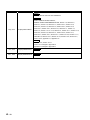
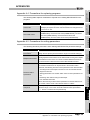
PRECAUTIONS FOR USE
(1) Interlink transfer and routing functions
The CC-Link IE Controller Network board cannot be used as a relay station for the
interlink transfer function or the routing function.
To use these functions, set a network module as a relay station.
(2) A personal computer equipped with PCI bus slot and PCI Express® slot
When CC-Link IE Controller Network board (Q80BD-J71GP21-SX,
Q80BD-J71GP21S-SX) supported with PCI bus is installed on a personal computer
which has both PCI bus slot and PCI Express® slot, link refresh time may be long
compared to when using a personal computer which has only PCI bus slot.
(3) Restrictions for functions depending on the personal computer or the
operating system
There are some restrictions for the functions or supported version depending on the
operating system or personal computer to be used.
Section 2.5 Operating Environment
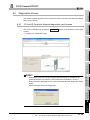
(4) Driver installation and updating
Do not install or update the driver other than the method written in the troubleshooting
in this manual.
The consistency between the driver and utility cannot be identified, and CCLink IE
Controller Network board may not operate properly.
A - 13
INTRODUCTION
Thank you for purchasing the Q80BD-J71GP21-SX, Q80BD-J71GP21S-SX, Q81BD-J71GP21-SX,
Q81BD-J71GP21S-SX CC-Link IE Controller Network interface board.
Before using this product, please read this manual and the relevant manuals carefully and develop
familiarity with the functions and performance of the Q80BD-J71GP21-SX, Q80BD-J71GP21S-SX,
Q81BD-J71GP21-SX, Q81BD-J71GP21S-SX CC-Link IE Controller Network interface board to handle the
product correctly.
CONTENTS
SAFETY PRECAUTIONS············································································································ A - 1
CONDITIONS OF USE FOR THE PRODUCT ················································································· A - 7
REVISIONS ····························································································································· A - 8
PRECAUTIONS FOR USE ········································································································ A - 13
INTRODUCTION····················································································································· A - 14
CONTENTS ··························································································································· A - 14
MANUAL ······························································································································· A - 20
HOW TO USE THIS MANUAL ··································································································· A - 21
GENERIC TERMS AND ABBREVIATIONS ·················································································· A - 22
ABBREVIATIONS AND SYMBOLS ····························································································· A - 23
PACKING LIST ······················································································································· A - 23
CHAPTER 1 OVERVIEW
1 - 1 to 1 - 4
1.1
Overview··················································································································· 1 - 1
1.2
Features ··················································································································· 1 - 2
CHAPTER 2 SYSTEM CONFIGURATION
2 - 1 to 2 - 11
2.1
System Configuration Using CC-Link IE Controller Network Board ········································ 2 - 1
2.2
Single Network System ································································································ 2 - 2
2.2.1
2.2.2
2.2.3
2.3
Configuration ······································································································· 2 - 2
Setting items ········································································································ 2 - 3
Available device ranges·························································································· 2 - 3
Multi-Network System ·································································································· 2 - 4
2.3.1
2.3.2
2.3.3
Configuration ······································································································· 2 - 4
Setting items ········································································································ 2 - 5
Available device range ··························································································· 2 - 5
2.4
Use in Multiple CPU System or Redundant CPU System ···················································· 2 - 6
2.5
Operating Environment ································································································ 2 - 7
CHAPTER 3 SPECIFICATIONS
3.1
A - 14
3 - 1 to 3 - 3
General Specifications ································································································· 3 - 1
3.2
Performance Specifications ···························································································3 - 2
3.3
Optical Fiber Cable Specifications ···················································································3 - 3
3.4
Buffer Memory ············································································································3 - 3
CHAPTER 4 FUNCTIONS
4 - 1 to 4 - 7
4.1
Function List ···············································································································4 - 1
4.2
Specifications on Cyclic Transmission Processing ······························································4 - 2
4.2.1
4.3
Cyclic transmission processing ·················································································4 - 2
Driver WDT function ·····································································································4 - 7
CHAPTER 5 PROCEDURES AND SETTINGS BEFORE OPERATION
5 - 1 to 5 - 28
5.1
Procedure before Operation···························································································5 - 1
5.2
Part Names and Settings·······························································································5 - 3
5.3
Installation··················································································································5 - 8
5.3.1
5.3.2
5.3.3
5.3.4
5.4
Wiring ····················································································································· 5 - 11
5.4.1
5.4.2
5.5
Handling precautions ······························································································5 - 8
Installation environment ··························································································5 - 9
Board installation ···································································································5 - 9
Setting Channel Numbers······················································································ 5 - 10
Controller network system ····················································································· 5 - 13
Wiring external power supply cable ········································································· 5 - 15
Test ························································································································ 5 - 17
5.5.1
5.5.2
5.5.3
5.5.4
5.5.5
5.5.6
Bus I/F test ········································································································· 5 - 18
H/W test············································································································· 5 - 19
Self-loopback test ································································································ 5 - 20
Circuit test ·········································································································· 5 - 22
Station-to-station test···························································································· 5 - 25
Communication test ····························································································· 5 - 27
CHAPTER 6 PARAMETER SETTINGS
6 - 1 to 6 - 25
6.1
Parameter Settings (Board Information Settings) ································································6 - 2
6.2
Parameter Setting Example ···························································································6 - 8
6.3
Network Range Assignment Settings ···············································································6 - 9
6.3.1
6.3.2
6.3.3
6.3.4
6.3.5
LB/LW settings ···································································································· 6 - 10
LX/LY settings····································································································· 6 - 13
Total number of link stations ·················································································· 6 - 15
Specifying I/O master station·················································································· 6 - 15
Specifying reserved stations ·················································································· 6 - 16
6.4
Equal Assignment Settings ·························································································· 6 - 17
6.5
Routing Parameter Settings ························································································· 6 - 20
6.6
Supplementary Settings ······························································································ 6 - 21
6.7
Driver Settings ·········································································································· 6 - 22
6.8
Event Settings··········································································································· 6 - 23
A - 15
6.9
Target Settings ··········································································································6 - 24
6.10 Refresh Parameter Setting···························································································6 - 25
CHAPTER 7 INSTALLING AND UNINSTALLING SOFTWARE PACKAGES
7 - 1 to 7 - 5
7.1
Installation and Uninstallation Precautions ······································································· 7 - 1
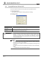
7.2
Installation ················································································································· 7 - 2
7.3
Uninstallation ············································································································· 7 - 5
CHAPTER 8 CC IE Control UTILITY
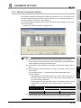
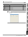
8.1
Overview··················································································································· 8 - 1
8.1.1
8.2
Board list screen ··································································································· 8 - 7
Channel number confirmation screen ········································································ 8 - 9
Board detail information screen···············································································8 - 10
Memory Test screen ·····························································································8 - 11
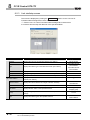
Setting Screen···········································································································8 - 12
8.4.1
8.4.2
8.4.3
8.4.4
8.4.5
8.4.6
8.4.7
8.4.8
8.4.9
8.5
Starting the utility ·································································································· 8 - 4
Ending the utility ··································································································· 8 - 5
Displaying manual································································································· 8 - 5
Checking the version information·············································································· 8 - 6
Board Information Screens···························································································· 8 - 7
8.3.1
8.3.2
8.3.3
8.3.4
8.4
List of functions ···································································································· 8 - 2
Operating Procedure ··································································································· 8 - 3
8.2.1
8.2.2
8.2.3
8.2.4
8.3
Parameter setting screen·······················································································8 - 12
Network range assignment screen···········································································8 - 15
Equal assignment screen·······················································································8 - 17
Routing parameter setting screen ············································································8 - 19
Supplementary setting screen·················································································8 - 20
Driver setting screen·····························································································8 - 21
Event setting screen ·····························································································8 - 23
Target setting screen ····························································································8 - 25
Refresh parameter setting screen············································································8 - 27
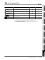
Diagnostics Screen ····································································································8 - 29
8.5.1
8.5.2
8.5.3
8.5.4
CC-Link IE Controller Network diagnostics result screen ··············································8 - 29
Communication test screen ····················································································8 - 36
Link start/stop screen····························································································8 - 38
Logging screen····································································································8 - 40
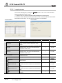
CHAPTER 9 DEVICE MONITOR UTILITY
9.1
List of the functions ······························································································· 9 - 1
Operating Procedure ··································································································· 9 - 1
9.2.1
9.2.2
9.2.3
9.2.4
A - 16
9 - 1 to 9 - 12
Overview··················································································································· 9 - 1
9.1.1
9.2
8 - 1 to 8 - 41
Starting the utility ·································································································· 9 - 2
Ending the utility ··································································································· 9 - 2
Displaying the Help screen······················································································ 9 - 2
Displaying the version information ············································································ 9 - 2
9.3
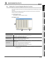
Setting the Batch Monitor Function ··················································································9 - 3
9.4
Setting the 16-point Register Monitor Function···································································9 - 4
9.5
Setting a Monitor Target································································································9 - 5
9.6
Setting a Device to be Monitored ····················································································9 - 6
9.7
Changing Word Device/Double Word Device Values···························································9 - 7
9.8
Tuning Bit Devices ON and OFF ·····················································································9 - 9
9.9
Switching a Display Format························································································· 9 - 11
9.10
Numerical Pad ········································································································· 9 - 12
CHAPTER 10 MELSEC DATA LINK LIBRARY
10 - 1 to 10 - 2
CHAPTER 11 PROGRAMMING
11 - 1 to 11 - 5
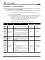
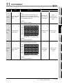
11.1
Precautions on Programming ······················································································· 11 - 1
11.1.1
11.2
Cyclic Transmission ··································································································· 11 - 3
11.2.1
11.3
Interlock related signals ························································································ 11 - 1
Station-based block data assurance ········································································ 11 - 4
Link Special Relays (SB) and Link Special Registers (SW) ················································· 11 - 5
CHAPTER 12 APPLICATION FUNCTIONS
12.1
Transient Transmission Function ·················································································· 12 - 2
12.1.1
12.1.2
12.1.3
12.1.4
12.2
Communication function ························································································ 12 - 3
Routing function ·································································································· 12 - 6
Group function ·································································································· 12 - 15
SEND/RECV function ························································································· 12 - 16
Event Setting Function······························································································ 12 - 20
CHAPTER 13 ERROR CODES
13.1
13 - 1 to 13 - 11
List of Error Messages in CC IE Control Utility ································································· 13 - 1
13.1.1
13.1.2
13.1.3
13.2
12 - 1 to 12 - 21
Error messages displayed on the board information screen ·········································· 13 - 2
Error messages displayed on the setting screen························································· 13 - 3
Error messages displayed on the diagnostics screen ·················································· 13 - 7
List of Error Messages in Device Monitor Utility······························································ 13 - 11
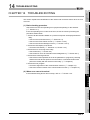
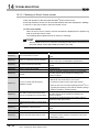
CHAPTER 14 TROUBLESHOOTING
14 - 1 to 14 - 31
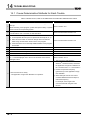
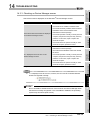
14.1
Cause Determination Methods for Each Trouble ······························································ 14 - 2
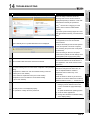
14.2
Troubleshooting of Installation/Uninstallation ··································································· 14 - 4
14.2.1
14.2.2
14.2.3
14.2.4
14.3
Installation failed·································································································· 14 - 4
Uninstallation failed ······························································································ 14 - 5
When the corrective action displayed on the screen is not effective at installation·············· 14 - 6
When the driver is not installed ··············································································· 14 - 9
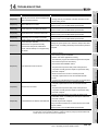
When CC-Link IE Controller Network Board did not Operate Normally ······························· 14 - 11
14.3.1
Checking personal computer and operating system ·················································· 14 - 11
A - 17
14.3.2
14.3.3
14.4
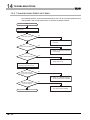
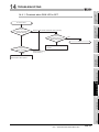
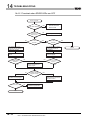
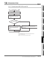
Flowchart when Data Link Failed················································································· 14 - 16
14.4.1
14.4.2
14.4.3
14.4.4
14.4.5
14.4.6
14.5
Checking on Event Viewer screen ········································································· 14 - 12
Checking on Device Manager screen ····································································· 14 - 15
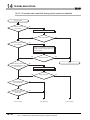
Flowchart when RUN LED is OFF ········································································· 14 - 17
Flowchart when SD/RD LEDs are OFF ··································································· 14 - 18
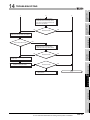
Flowchart when ERR. LED turned ON ···································································· 14 - 19
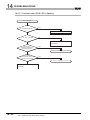
Flowchart when data link among whole system is disabled ········································· 14 - 20
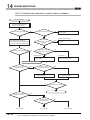
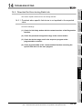
Flowchart when data link to specific station is disabled ·············································· 14 - 22
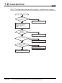
Flowchart when RUN LED is flashing ····································································· 14 - 24
Flowchart for Error during Data Link············································································· 14 - 25
14.5.1
14.5.2
14.5.3
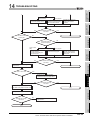
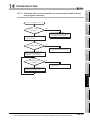
Flowchart when specific link device is not updated to the expected value ······················ 14 - 25
Flowchart when data cannot be written or read with user program································ 14 - 26
Flowchart when communications are occasionally disabled during user program
execution ········································································································· 14 - 27
14.6
When External Power Supply Function did not Correctly Operate ······································ 14 - 28
14.7
Actions for WDT Error ······························································································· 14 - 29
14.7.1
14.7.2
Board WDT error ······························································································· 14 - 29
Driver WDT error ······························································································· 14 - 29
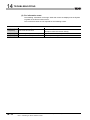
14.8
Measures for Slow Personal Computer Operation··························································· 14 - 30
14.9
Information Required for Inquiries················································································ 14 - 31
APPENDICES
App - 1 to App - 53
Appendix 1
Precautions for Accessing Redundant CPU System···············································App - 1
Appendix 2
Network Status at Power ON/OFF and Board Reset During Data Linking ················· App - 10
Appendix 2.1
Network status at power ON/OFF······························································ App - 10
Appendix 2.2
Network status at board reset ··································································· App - 15
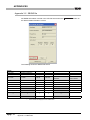
Appendix 3 File Output ·································································································· App - 16
Appendix 3.1
Parameter file ······················································································· App - 16
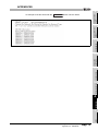
Appendix 3.2
SB/SW file···························································································· App - 17
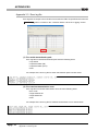
Appendix 3.3
Error log file ·························································································· App - 19
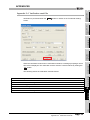
Appendix 3.4
Verification result file ·············································································· App - 20
Appendix 4 Comparison with the MELSECNET/H Board ······················································ App - 21
Appendix 4.1
Comparison of boards············································································· App - 21
Appendix 4.2
Comparison of MELSECNET utilities ························································· App - 23
Appendix 4.3
Comparison of device monitor utilities ························································ App - 23
Appendix 4.4
Precautions for replacing programs ··························································· App - 24
Appendix 4.5
Precautions for setting parameters ···························································· App - 24
Appendix 4.6
Comparison of the data link library functions················································ App - 25
Appendix 5 Combinations with Existing Software ································································ App - 26
Appendix 6
Checking Serial Number and Function Version ··················································· App - 27
Appendix 7
New and Improved Functions ·········································································· App - 29
Appendix 7.1
Change of hardware function···································································· App - 29
Appendix 7.2
Update of software package····································································· App - 29
Appendix 8 Restrictions for Operating System ···································································· App - 30
Appendix 9
Warning Message Appears on Windows® ·························································· App - 31
Appendix 9.1
Overview of warning message ·································································· App - 31
Appendix 9.2
Methods for preventing the warning message ·············································· App - 32
Appendix 10 Behavior When Personal Computer Enters Power Save Mode or Fast Startup ·········· App - 38
A - 18
Appendix 10.1
Behavior when the personal computer enters the power save mode
(standby, hibernate) ··············································································· App - 38
Appendix 10.2 Behavior when the personal computer enters the power save mode
(hibernate, sleep) ·················································································· App - 40
Appendix 10.3 Behavior when the fast startup function is enabled ······································· App - 41
Appendix 11 MELSECPowerManager ················································································ App - 42
Appendix 11.1 Installing MELSECPowerManager ···························································· App - 42
Appendix 11.2 Uninstalling MELSECPowerManager························································· App - 42
Appendix 11.3 Checking MELSECPowerManager···························································· App - 43
Appendix 12 EMC AND LOW VOLTAGE DIRECTIVE ··························································· App - 45
Appendix 12.1 Requirements for Conformance to EMC Directive········································· App - 45
Appendix 12.2 Requirements for Conformance to Low Voltage Directive······························· App - 48
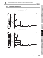
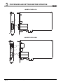
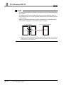
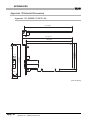
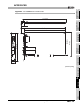
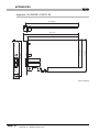
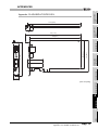
Appendix 13 External Dimensions ····················································································· App - 49
Appendix 13.1
Appendix 13.2
Appendix 13.3
Appendix 13.4
INDEX
Q80BD-J71GP21-SX ············································································· App - 49
Q80BD-J71GP21S-SX ··········································································· App - 50
Q81BD-J71GP21-SX ············································································· App - 51
Q81BD-J71GP21S-SX ··········································································· App - 52
Index - 1 to Index - 2
A - 19
MANUAL
The following is the manual relevant to this product.
Please purchase it if necessary.
Relevant Manual
Manual Number
Manual Name
(Model Code)
MELSEC-Q CC-Link IE Controller Network Reference Manual
This manual explains the system configuration, performance specification, functions, handling and wiring
instructions, and troubleshooting of the CC-Link IE Controller Network.
(Sold separately)
MELSEC Data Link Library Reference Manual
This manual explains the programming, function specifications, and sample programming of the MELSEC data
link library.
(Sold separately)
SH-080668ENG
(13JV16)
SH-081035ENG
(13JV25)
Remarks
MELSEC Data Link Library Reference Manual is stored on the CD-ROM of
software package with PDF file.
Manuals in printed form are sold separately for single purchase. Order a manual
by quoting the manual number (model code) listed in the table above.
A - 20
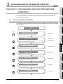
HOW TO USE THIS MANUAL
Relevant sections are listed below for each purpose for using the CC-Link IE Controller
Network board.
Refer to each section when you want to know the following:
(1) Overview and features of CC-Link IE Controller Network board (Chapter 1)
Chapter 1 gives an overview of the CC-Link IE Controller Network board and its
features.
(2) System configuration (Chapter 2)
Chapter 2 explains the system configuration.
(3) Specifications of CC-Link IE Controller Network board (Chapter 3)
Chapter 3 gives the specifications of the CC-Link IE Controller Network board.
(4) Functions of CC-Link IE Controller Network board (Chapter 4)
Chapter 4 gives the functions of the CC-Link IE Controller Network board.
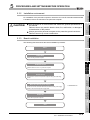
(5) Preparatory procedures and setting of CC-Link IE Controller Network
board (Chapter 5)
Chapter 5 gives the procedures and setting to be done before starting the operation.
(6) Parameter setting for CC-Link IE Controller Network board (Chapter 6)
Chapter 6 describes the parameter setting.
(7) Installing and uninstalling procedures of software package (Chapter 7)
Chapter 7 gives the procedure for installing and uninstalling the software package.
(8) Detailed operation method of each utility (Chapter 8 and Chapter 9)
Chapter 8 and Chapter 9 explain the detailed operation methods for each utility.
(9) MELSEC data link library (Chapter 10)
Chapter 10 gives overview of the MELSEC data link library.
(10)Interlock related signals (Chapter 11)
Chapter 11 explains the interlock related signals.
(11)Application functions (Chapter 12)
Chapter 12 explains application functions of the CC-Link IE Controller Network board.
(12)Error codes (Chapter 13)
Chapter 13 describes the error codes.
(13)Troubleshooting (Chapter 14)
Chapter 14 provides information on troubleshooting.
A - 21
GENERIC TERMS AND ABBREVIATIONS
Unless otherwise specified, this manual uses the following generic terms and
abbreviations to describe the CC-Link IE Controller Network interface board.
Generic Term/
Description
Abbreviation
Q80BD-J71GP21-SX
Q80BD-J71GP21S-SX
Q81BD-J71GP21-SX
Q81BD-J71GP21S-SX
CC-Link IE Controller
Abbreviation for Q80BD-J71GP21-SX CC-Link IE Controller Network interface board
Abbreviation for Q80BD-J71GP21S-SX CC-Link IE Controller Network interface board
Abbreviation for Q81BD-J71GP21-SX CC-Link IE Controller Network interface board
Abbreviation for Q81BD-J71GP21S-SX CC-Link IE Controller Network interface board
Generic term for Q80BD-J71GP21-SX, Q80BD-J71GP21S-SX, Q81BD-J71GP21-SX,
Network board
Q81BD-J71GP21S-SX CC-Link IE Controller Network interface board
CC-Link IE Controller
Network board with
Generic term for Q80BD-J71GP21S-SX, Q81BD-J71GP21S-SX CC-Link IE Controller Network
external power supply
interface board
function
SW1DNC-MNETG-B
GX Developer
GX Works2
Network module
MELSECNET/H board
MELSECNET/H module
MELSECNET/H
MELSECNET/10
Board WDT
Driver WDT
A - 22
Product name of the software package for CC-Link IE Controller Network board
General product name for SW8D5C-GPPW-E, SW8D5C-GPPW-EA, SW8D5C-GPPW-EV,
SW8D5C-GPPW-EVA
General product name for SWnDNC-GXW2-E, SWnDNC-GXW2-EA
("n" denotes the version number.)
Abbreviation for CC-Link IE Controller Network module
Generic term for Q80BD-J71LP21-25, Q81BD-J71LP21-25, Q80BD-J71LP21S-25,
Q80BDJ71LP21G, Q80BD-J71LP21GE, Q80BD-J71BR11 MELSECNET/H interface board
Abbreviation for Q series MELSECNET/H network module
Abbreviation for Q series MELSECNET/H network system
Abbreviation for AnU or QnA/Q4AR series MELSECNET/10 network system
Abbreviation for the watchdog timer that monitors the operation of network board
Abbreviation for the watchdog timer that monitors the communication status between a network
board and a personal computer, or operating status of a personal computer
ABBREVIATIONS AND SYMBOLS
The following abbreviations and symbols are used in this manual.
(1) Abbreviations for control station and normal station, and symbol format
This section explains abbreviations for control station and normal station, and symbol
format to be used in this manual.
(a) Abbreviations
Abbreviation
Station status
MP
Control station
NS
Normal station
(b) Symbol format
MP
Station number (1 to 120)
Abbreviation
Network No. (1 to 239)
[Example]
1) Network No.3, control station and station number 6: 3MP6
2) Network No.5, normal station and station number 3: 5NS3
PACKING LIST
The packing list of the CC-Link IE Controller Network board is given below.
Item
Board
Quantity
1
Connector set (for external power supply cable)
(Q80BD-J71GP21S-SX, Q81BD-J71GP21S-SX only)
"Before Using the Product"
Software package
(CD-ROM)*1
Software license agreement
1
1
1
1
*1: Manuals are stored on the CD-ROM in PDF format.
A - 23
1
OVERVIEW
CHAPTER 1 OVERVIEW
This manual explains the specifications, functions, preparatory procedures and setting,
programming, and troubleshooting of the CC-Link IE Controller Network board.
When applying program examples introduced in this manual to the actual system, it is
necessary to perform a sufficient examination to make sure they don't cause any error in
the system control.
For construction of the CC-Link IE Controller Network, refer to the following manual.
CC-Link IE Controller Network Reference Manual
1.1
Overview
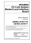
The CC-Link IE Controller Network board allows connection of a personal computer to a
CC-Link IE Controller Network, realizing high-speed and large-volume data
communications between the computer and programmable controllers.
High-speed and
large-volume data
communication
CC-Link IE Controller Network
(CC-Link IE Controller Network board)
POINT
(1) The CC-Link IE Controller Network is a system developed to improve the
MELSECNET/H network system (PLC-to-PLC network), allowing
communications of a larger data volume at a higher speed.
For details of the comparison between the CC-Link IE Controller Network
board and the MELSECNET/H board, refer to the following Appendix.
Appendix 4 Comparison with the MELSECNET/H Board
(2) CC-Link IE Controller Network boards, MELSECNET/H boards, and
MELSECNET/H modules cannot be mixed in the same network.
(Must be separated into different networks.)
• CC-Link IE Controller Network board:
Used for CC-Link IE Controller Network
• MELSECNET/H board or MELSECNET/H module:
Used for MELSECNET/H or MELSECNET/10
1-1
1.1 Overview
1
OVERVIEW
1
OVERVIEW
Features
The features of the CC-Link IE Controller Network board are shown below.
(1) Personal computer can be incorporated into CC-Link IE Controller
Network.
By installing the CC-Link IE Controller Network board to a personal computer, the
personal computer can be used as a control station or normal station of the CC-Link
IE Controller Network.
(2) Universal PCI, PCI Express® are applicable.
SYSTEM
CONFIGURATION
2
3
SPECIFICATIONS
(a) Q80BD-J71GP21-SX, Q80BD-J71GP21S-SX
The following PCI slots are applicable.
• 5 V slot
• 3.3 V slot
• 64-bit slot
• PCI-X slot
4
(b) Q81BD-J71GP21-SX, Q81BD-J71GP21S-SX
To utilize the CC-Link IE Controller Network board, just install it to a personal
computer and install the software package.
Using the CC IE Control utility, various settings such as channel numbers and station
numbers can be configured easily.
5
PROCEDURES AND
SETTINGS BEFORE
OPERATION
(3) Operation is easy.
FUNCTIONS
PCI Express® is applicable.
PARAMETER
SETTINGS
6
INSTALLING AND
UNINSTALLING
SOFTWARE PACKAGES
7
8
CC IE Control
UTILITY
1.2
1.2 Features
1-2
1
OVERVIEW
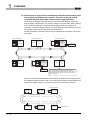
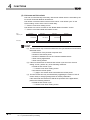
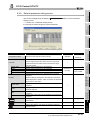
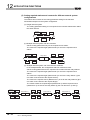
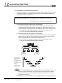
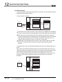
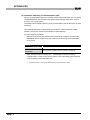
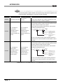
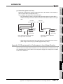
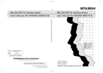
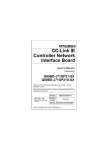
(4) External power supply allows continuous network communication even
during power-off of personal computer. (Function of the CC-Link IE
Controller Network board with external power supply function)
Since power is supplied externally, the CC-Link IE Controller Network board with
external power supply function can continue network communication (baton passing)
even if a personal computer is powered off and data link cannot be performed.
Therefore, a normally operating station connected between other stations with poweroff computers will not be disconnected from the data link.
Another advantage is that the link scan time is stabilized since loopback can be also
prevented.
Control station (No.1)
Normal station (No.2)
Q80BD-
QCPU
J71GP21-SX
Normal station (No.3)
QJ71GP21
Q80BD-
-SX
J71GP21S-SX
Q81BD-
Q81BD-
J71GP21-SX
J71GP21S-SX
Normal station (No.6)
Normal station (No.5)
External power
supply
QCPU
External power
supply
QJ71GP21
-SX
Normal station (No.4)
Since external power is supplied to stations No.3 and
No.5, networking of all stations continues normally.
If the boards on stations No.3 and No.5 do not have the
external power supply function, they are disconnected
from the network.
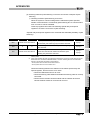
When CC-Link IE Controller Network boards without the external power supply function
are installed to station number 3 and 5, and if personal computers of these stations are
powered off, station number 3, 4, and 5 will be disconnected from the network.
Personal computer
Station No.1
Station No.2
Station No.3
Station No.6
Station No.5
Station No.4
Personal computer
1-3
1.2 Features
Disconnected
OVERVIEW
1
The event function monitors link devices using the CC-Link IE Controller Network
board, and notifies events to the user program when the set conditions are met.
(7) Keeping application portability with MELSECNET/H board
By only changing settings such as the total number of boards (CC-Link IE Controller
Network boards) installed to a personal computer and channel numbers, any existing
user program created by a MELSECNET/H or MELSECNET/10 board can be utilized.
(8) Drivers are available for each OS.
Since various types of drivers are available, a system suitable to the user environment
can be easily constructed.
For details on the compatible operating system, refer to Section 2.5.
2
SYSTEM
CONFIGURATION
(6) Supporting event function
3
SPECIFICATIONS
Any type of CC-Link IE Controller Network boards including those with external power
supply occupies only one slot.
OVERVIEW
(5) Occupying one PCI bus slot
4
With supported Microsoft® Visual Basic® and Microsoft® Visual C++® functions,
remote control of programmable controllers and device reading/writing can be
performed, and user programs can be created easily.
FUNCTIONS
(9) User programming functions are available.
By specifying a logical station number with the CC IE Control utility, a multiple CPU
system is accessible.
PROCEDURES AND
SETTINGS BEFORE
OPERATION
5
(10)Supporting Multiple CPU system
PARAMETER
SETTINGS
6
INSTALLING AND
UNINSTALLING
SOFTWARE PACKAGES
7
8
CC IE Control
UTILITY
1
1.2 Features
1-4
2
SYSTEM CONFIGURATION
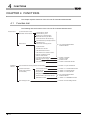
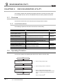
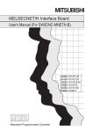
CHAPTER 2 SYSTEM CONFIGURATION
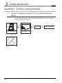
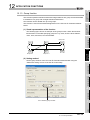
2.1
System Configuration Using CC-Link IE Controller Network
Board
A system configuration where the CC-Link IE Controller Network board is installed to a
personal computer is shown below.
Installed
Connection
Connection
Optical fiber
cable
Personal computer
CC-Link IE Controller
Network board
Installed
SW1DNC-MNETG-B
2-1
2.1 System Configuration Using CC-Link IE Controller Network Board
CC-Link IE Controller Network
2
SYSTEM CONFIGURATION
1
Configuration
3
IN
OUT
QJ71
GP21-SX
IN
4
OUT
FUNCTIONS
OUT
QCPU
5
PROCEDURES AND
SETTINGS BEFORE
OPERATION
IN
QJ71
GP21-SX
6
PARAMETER
SETTINGS
Q80BDJ71GP21-SX
QCPU
Normal station
Station No.n n < 120
7
INSTALLING AND
UNINSTALLING
SOFTWARE PACKAGES
Personal
computer
Normal station
Station No.2
8
CC IE Control
UTILITY
Control station
Station No.1
SPECIFICATIONS
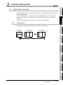
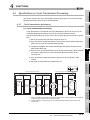
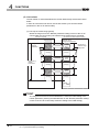
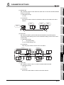
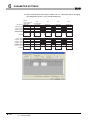
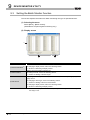
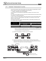
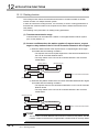
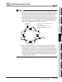
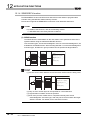
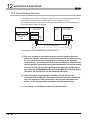
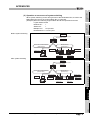
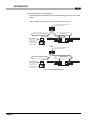
A configuration example of a single network system is shown below.
Power supply
2.2.1
2
SYSTEM
CONFIGURATION
A single network system is a system that connects a control station and normal stations
with optical fiber cables.
A total of 120 stations, 1 control station and 119 normal stations, can be connected.
A control station can be any station No.s. (One control station can be connected per
network.)
In the system chart below, the station No.1 is set as the control station.
OVERVIEW
Single Network System
Power supply
2.2
2.2 Single Network System
2.2.1 Configuration
2-2
2
SYSTEM CONFIGURATION
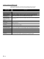
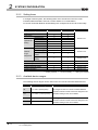
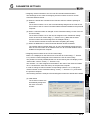
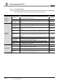
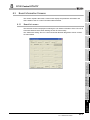
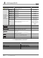
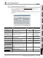
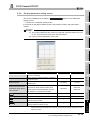
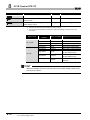
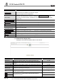
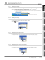
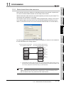
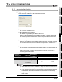
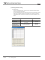
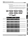
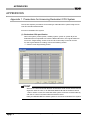
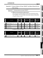
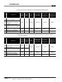
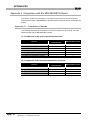
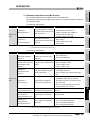
2.2.2
Setting items
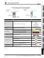
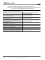
In a single network system, the following items are to be set when the CC-Link IE
Controller Network board is used as a control station or a normal station.
CC-Link IE Controller Network board settings are configured in the CC IE Control utility.
Setting item
Target board specification
Board
Channel No.
Network type
Mode
Operational
Network No.
setting
Group No.
Station No.
LB/LW settings
LX/LY settings
Network
Specify reserved
range
station
assignment
Supplementary
Control station
Normal station
Section 8.4.5
Section 8.4.6
Section 8.4.7
Section 8.4.8
Section 8.4.9
Section 8.4.4
setting
Driver setting
Event setting
Target setting
Refresh parameter setting
Routing parameter
Reference
Section 8.4.1
Section 8.4.2
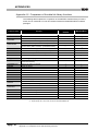
: Setting required : Set as necessary : Setting not required
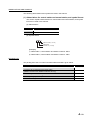
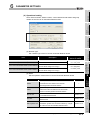
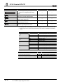
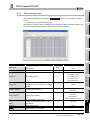
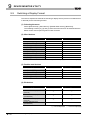
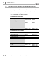
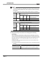
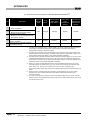
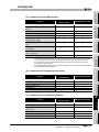
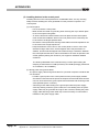
2.2.3
Available device ranges
The following device ranges can be used on the CC-Link IE Controller Network board.
Device
LB
Available range
0H to 7FFFH (32768 points)
Remarks
The ranges for each CC-Link IE Controller Network
board and network module need to be assigned in the
LW
0H to 1FFFFH (131072 points)
parameter setting for the control station.
LX
0H to 1FFFH (8192 points)
The ranges for each CC-Link IE Controller Network
LY
0H to 1FFFH (8192 points)
board and network module need to be assigned in the
2-3
2.2 Single Network System
2.2.2 Setting items
parameter setting for the control station.
2
SYSTEM CONFIGURATION
1
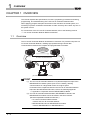
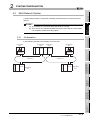
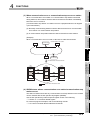
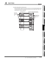
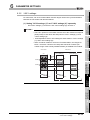
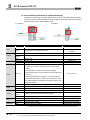
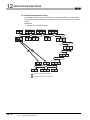
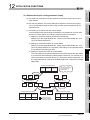
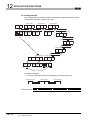
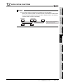
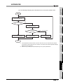
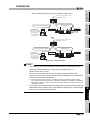
A multi-network system is composed of multiple networks that are connected by relay
stations.
2
POINT
(1) Any network No. can be set within the range of 1 to 239.
(2) The CC-Link IE Controller Network board cannot be used as a relay station.
Use a network module as a relay station.
3
Configuration
SPECIFICATIONS
2.3.1
In the following example, two networks are connected.
Power supply
Network No.1
QCPU
Control station
2MP1
QJ71
QJ71
GP21-SX
GP21-SX
Normal station
2NS2
4
Q80BDJ71GP21-SX
FUNCTIONS
Normal station
1NS2
Control station
1MP1
Q80BDJ71GP21-SX
OVERVIEW
Multi-Network System
SYSTEM
CONFIGURATION
2.3
Network No.2
PROCEDURES AND
SETTINGS BEFORE
OPERATION
QJ71
GP21-SX
Normal station
2NS3
6
PARAMETER
SETTINGS
Normal station
1NS3
QCPU
7
INSTALLING AND
UNINSTALLING
SOFTWARE PACKAGES
QJ71
GP21-SX
8
CC IE Control
UTILITY
QCPU
Power supply
Power supply
5
2.3 Multi-Network System
2.3.1 Configuration
2-4
2
SYSTEM CONFIGURATION
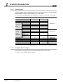
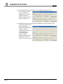
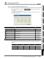
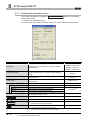
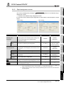
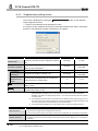
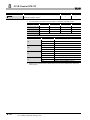
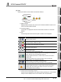
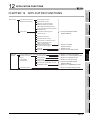
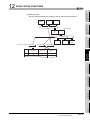
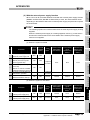
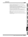
2.3.2
Setting items
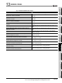
In a multi-network system, the following items are to be set when the CC-Link IE Controller
Network board is used as a control station or a normal station.
CC-Link IE Controller Network board settings are configured in the CC IE Control utility.
Setting item
Target board specification
Board
Channel No.
Network type
Mode
Operational
Network No.
setting
Group No.
Station No.
LB/LW settings
LX/LY settings
Network
Specify reserved
range
station
assignment
Supplementary
Control station
Normal station
Section 8.4.5
Driver setting
Event setting
Target setting
Section 8.4.6
Section 8.4.7
Section 8.4.8
Refresh parameter setting
Routing parameter
Section 8.4.9
Section 8.4.4
setting
Reference
Section 8.4.1
Section 8.4.2
: Setting required : Set as necessary : Setting not required
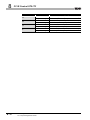
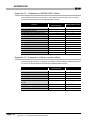
2.3.3
Available device range
The same device ranges as those of a single network system can be used.
Section 2.2.3 Available device ranges.
2-5
2.3 Multi-Network System
2.3.2 Setting items
2
SYSTEM CONFIGURATION
1
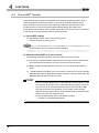
POINT
3
SPECIFICATIONS
When a CC-Link IE Controller Network board with a serial number whose first five
digits are 10091 or lower, or an SW1DNC-MNETG-B with the software Version
1.04E or earlier is used, the redundant CPU system cannot be accessed directly
with the CC-Link IE Controller Network interface board.
Relay the MELSECNET/H network system to access the redundant CPU system.
2
SYSTEM
CONFIGURATION
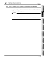
To access a multiple CPU system or redundant CPU system, the "Target setting" screen
setting must be completed.
Section 8.4.8 Target setting screen
OVERVIEW
Use in Multiple CPU System or Redundant CPU System
FUNCTIONS
4
PROCEDURES AND
SETTINGS BEFORE
OPERATION
5
PARAMETER
SETTINGS
6
INSTALLING AND
UNINSTALLING
SOFTWARE PACKAGES
7
8
CC IE Control
UTILITY
2.4
2.4 Use in Multiple CPU System or Redundant CPU System
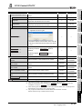
2-6
2
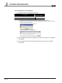
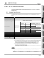
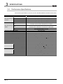
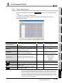
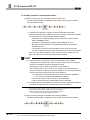
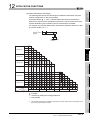
2.5
SYSTEM CONFIGURATION
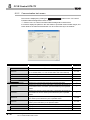
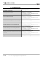
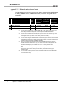
Operating Environment
The following table shows the operating environment for the CC-Link IE Controller
Network board.
Item
Personal computer
Description
Windows® supported personal computer
CPU
System requirements of the operating system must be met.
Required memory
PCI bus
For Q80BD-J71GP21-SX, Q80BD-J71GP21S-SX
• Compliant with PCI standard Rev.2.2 (3.3VDC/5VDC, 32-bit bus, Basic clock 33MHz)
specifications
For Q81BD-J71GP21-SX, Q81BD-J71GP21S-SX
PCI Express®
• Compliant with PCI Express® standard Rev.1.1 (3.3VDC, Link width 1lane, Basic clock
bus specifications
100MHz)
Microsoft® Windows® 2000 Professional Operating System Service Pack4 or later*3
Microsoft® Windows® XP Home Edition Operating System Service Pack2 or later*5
Microsoft® Windows® XP Professional Operating System Service Pack2 or later*5
Microsoft® Windows Server® 2003 R2, Standard Edition Operating System
Service Pack2 or later*5
Microsoft® Windows Server® 2003 R2, Enterprise Edition Operating System
Service Pack2 or later*5
Microsoft® Windows Server® 2003 R2, Standard x64 Edition Operating System
Service Pack2 or later*5
Microsoft® Windows Server® 2003 R2, Enterprise x64 Edition Operating System
Service Pack2 or later*5
Microsoft® Windows Vista® Home Basic Operating System*5
Microsoft® Windows Vista® Home Premium Operating System*5
Microsoft® Windows Vista® Business Operating System*5
Microsoft® Windows Vista® Ultimate Operating System*5
Microsoft® Windows Vista® Enterprise Operating System*5
Microsoft® Windows Server® 2008 Standard Operating System*5
Operating system
*1 *2
(English version)
Microsoft® Windows Server® 2008 Enterprise Operating System*5
Microsoft® Windows Server® 2008 Standard x64 Edition Operating System*5
Microsoft® Windows Server® 2008 Enterprise x64 Edition Operating System*5
Microsoft® Windows Server® 2008 R2 Standard Operating System
Microsoft® Windows Server® 2008 R2 Enterprise Operating System
Microsoft® Windows® 7 Home Premium (32-bit version / 64-bit version) Operating System
Microsoft® Windows® 7 Professional (32-bit version / 64-bit version) Operating System
Microsoft® Windows® 7 Ultimate (32-bit version / 64-bit version) Operating System
Microsoft® Windows® 7 Enterprise (32-bit version / 64-bit version) Operating System
Microsoft® Windows Server® 2012 Standard Operating System
Microsoft® Windows Server® 2012 R2 Standard Operating System
Microsoft® Windows® 8 (32-bit version / 64-bit version) Operating System
Microsoft® Windows® 8 Pro (32-bit version / 64-bit version) Operating System
Microsoft® Windows® 8 Enterprise (32-bit version / 64-bit version) Operating System
Microsoft® Windows® 8.1 (32-bit version / 64-bit version) Operating System
Microsoft® Windows® 8.1 Pro (32-bit version / 64-bit version) Operating System
Monitor
Hard disk space
2-7
Microsoft® Windows® 8.1 Enterprise (32-bit version / 64-bit version) Operating System
Resolution: 1024 768 dots or higher
1GB or more
2.5 Operating Environment
2
SYSTEM CONFIGURATION
1
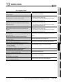
Description
®
OVERVIEW
Microsoft Visual Basic 6.0
Microsoft® Visual Basic® .NET 2003
Microsoft® Visual Studio® 2005 Visual Basic®
2
Microsoft® Visual Studio® 2008 Visual Basic®
®
Microsoft Visual Studio 2010 Visual Basic
®
SYSTEM
CONFIGURATION
®
Microsoft® Visual Studio® 2012 Visual Basic®
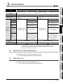
Programming language
Microsoft® Visual Studio® 2013 Visual Basic®
(English version)*2 *4
Microsoft® Visual C++® 6.0
Microsoft® Visual C++® .NET 2003
3
Microsoft® Visual Studio® 2005 Visual C++®
SPECIFICATIONS
Microsoft® Visual Studio® 2008 Visual C++®
Microsoft® Visual Studio® 2010 Visual C++®
Microsoft® Visual Studio® 2012 Visual C++®
Microsoft® Visual Studio® 2013 Visual C++®
*1: Windows® XP (64-bit version) and Windows Vista® (64-bit version) are not supported.
*2: For a combination of the operation system and the programming language, refer to the Microsoft®
Knowledge Base.
*3: Applicable to Q80BD-J71GP21-SX, Q80BD-J71GP21S-SX only.
Not supported by SW1DNC-MNETG-B Version 1.16S or later. When using one of these operating
system, use SW1DNC-MNETG-B Version 1.15R or earlier. SW1DNC-MNETG-B Version 1.15R
and its supported manual are stored on the CD-ROM of this product.
(Appendix 8)
*4: When creating 64-bit version Visual Basic application to be used for the MELSEC data link library,
use Visual Studio® 2010 or later because .NET Framework 4.0 or .NET Framework compatible
with .NET Framework 4.0 is required.
*5: Not supported by SW1DNC-MNETG-B Version 1.19V or later. When using one of these operating
system, use SW1DNC-MNETG-B Version 1.18U or earlier. SW1DNC-MNETG-B Version 1.18U
and its supported manual are stored on the CD-ROM of this product.
(Appendix 8)
4
FUNCTIONS
®
5
PROCEDURES AND
SETTINGS BEFORE
OPERATION
Item
PARAMETER
SETTINGS
6
INSTALLING AND
UNINSTALLING
SOFTWARE PACKAGES
7
CC IE Control
UTILITY
8
2.5 Operating Environment
2-8
2
SYSTEM CONFIGURATION
(1) Instructions for personal computer
(a) PCI standard
When a personal computer which is not compliant with the PCI or PCI Express®
standard is used, troubles caused by failures such as a contact failure or
operation error may occur.
For details of the number of boards that can be installed, installation slots, and
occupied slots, refer to the performance specifications in Section 3.2.
(b) Added operating environment
Operating environment
Supported version of SW1DNC-MNETG-B
Multiprocessor
Version 1.05F or later
(2) Instructions for operating system
(a) Supported version of SW1DNC-MNETG-B
Supported version of SW1DNC-MNETG-B
Operating system
Windows® 2000
Windows®
XP
Windows Server® 2003 R2 (32-bit version)
Windows Server® 2003 R2 (64-bit version)
Windows
Vista®
Q80BD-J71GP21-SX,
Q81BD-J71GP21-SX,
Q80BD-J71GP21S-SX
Q81BD-J71GP21S-SX
Version 1.15R or earlier
(Not supported)
Version 1.18U or earlier
Version 1.12N to 1.18U
Version 1.02C to 1.18U
Windows Server® 2008 (32-bit version)
®
Version 1.11M to 1.18U
Windows Server 2008 (64-bit version)
Version 1.12N to 1.18U
Windows®
Version 1.11M or later*1
7 (32-bit version)
Windows Server® 2008 R2
®
Windows 7 (64-bit version)
Version 1.12N to 1.18U
Version 1.12N or later*1
Version 1.12N or later*1
Windows Server® 2012
Windows® 8
Version 1.16S or later
Version 1.16S or later
Windows Server® 2012 R2
Windows® 8.1
Version 1.17T or later
Version 1.17T or later
*1: When using SW1DNC-MNETG-B Version 1.19V or later, apply Service Pack1 and Windows®
security update program KB3033929. Use SW1DNC-MNETG-B Version 1.18U or earlier, if
Service Pack1 and KB3033929 cannot be applied. SW1DNC-MNETG-B Version 1.18U and its
supported manual are stored on the CD-ROM of this product. (Appendix 8 Restrictions for
Operating System)
(b) User authority
Log on as a user having administrator authority.
• Installation, uninstallation and usage of utilities are available only by the
administrator's authority.
• Installation and uninstallation are available only by the administrator's
authority.
• The Usage of utilities is available only by the administrator's authority.
2-9
2.5 Operating Environment
SYSTEM CONFIGURATION
When updating Windows® 8.1, install SW1DNC-MENTG-B with the software
Version 1.17T or later after uninstalling the software package and updating
Windows® 8.1.
(e) The functions cannot be used
The following functions of operating system cannot be used. If an attempt is made
to use any of the following functions, this product may not operate normally.
•
•
•
•
•
•
•
•
•
•
•
•
•
•
Activating the application with Windows compatible mode.
Simplified user switch-over
Remote desktop
Large font size (Advanced setting of screen property)
DPI setting other than 100% (set the size of text and illustration other than
[smaller-100%])
Power save mode (Standby, Hibernate, Sleep)
Fast startup
The language switching function set by Regional and Language Options
Windows XP Mode
Windows Touch or Touch
Modern UI
Client Hyper-V
Server Core Installation
Upgrade the operating system
SYSTEM
CONFIGURATION
Updating Windows® 8.1 is not supported.
3
SPECIFICATIONS
(d) Update Windows® 8.1
2
4
FUNCTIONS
• Windows Server® 2012
• Windows Server® 2012 R2
• Windows® 8
• Windows® 8.1
Enable the .NET Framework 3.5 (including .NET 2.0 or 3.0) in "Turn Windows
features on or off" on the control panel.
5
PROCEDURES AND
SETTINGS BEFORE
OPERATION
(c) .NET Framework 3.5
When using one of the following operating system, .NET Framework 3.5 is required.
OVERVIEW
1
6
2.5 Operating Environment
2 - 10
7
INSTALLING AND
UNINSTALLING
SOFTWARE PACKAGES
• When exiting the operating system, always shut down the computer.
• The behavior of the board and the personal computer when the personal
computer enters the power save mode differs according to the operating
system.
For details of error codes and messages when the power save mode set
by a user or a program is entered, refer to the following appendix.
Appendix 10 Behavior When Personal Computer Enters Power Save
Mode or Fast Startup
• Upgrading the operating system is not supported. Install SW1DNCMNETG-B by following the procedure shown below.
1) Uninstall SW1DNC-MNETG-B.
2) Upgrade the operating system.
3) Install SW1DNC-MNETG-B with the software version supporting the
upgraded operating system.
PARAMETER
SETTINGS
Remarks
8
CC IE Control
UTILITY
2
2
SYSTEM CONFIGURATION
(3) Instructions for user program
(a) Supported version of SW1DNC-MNETG-B
User program
Supported version of
SW1DNC-MNETG-B
32-bit version user program
*1
All versions
64-bit version user program
*2
Version 1.12N or later
*1: Programs can be created and executed on the 64-bit version operating system.
*2: Programs can be created on the 32-bit version operating system, however, the following screen
appears and cannot be executed.
<When using Windows® XP (32-bit version)>
<When using Windows® 7 (32-bit version)>
(b) User programs created in the Japanese environment work only in the Japanese
environment.
(c) User programs created in the English environment work only in the English
environment.
2 - 11
2.5 Operating Environment
3
SPECIFICATIONS
1
This chapter explains general and performance specifications of CC-Link IE Controller
Network board.
The following table shows the general specifications of CC-Link IE Controller Network
board.
3
Specification
0 to 55 °C
SPECIFICATIONS
-25 to 75 °C
5 to 95 % RH, non-condensing
Under intermittent vibration
Constant
Frequency
Compliant with
Vibration resistance
JIS B 3502 and
acceleration
3.5 mm
8.4 to 150 Hz
9.8 m/s2
—
5 to 8.4 Hz
—
8.4 to 150 Hz
4.9 m/s2
1.75 mm
m/s2,
—
directions
Sweep count
—
3 times each in X, Y, Z directions)
No corrosive gases
0 to 2000 m
Inside a control panel
*2
5
6
II or less
Pollution degree*3
4
each in X, Y, Z
Under continuous vibration
Constant
Half amplitude
acceleration
Compliant with JIS B 3502 and IEC 61131-2 (147
Operating altitude*1
Installation location
*1: Do not use or store the board under pressure higher than the atmospheric pressure of altitude 0m.
Doing so may cause malfunction.
*2: This indicates the section of the power supply to which the equipment is assumed to be connected
between the public electrical power distribution network and the machinery within premises.
Category II applies to equipment for which electrical power is supplied from fixed facilities.
The surge voltage withstand level for up to the rated voltage of 300V is 2500V.
*3: This index indicates the degree to which conductive material is generated in terms of the
environment in which the equipment is used.
Pollution degree 2 is when only non-conductive pollution occurs. A temporary conductivity caused
by condensing must be expected occasionally.
Remarks
PARAMETER
SETTINGS
2 or less
7
8
The general specifications both CC-Link IE Controller Network board and a
personal computer must be satisfied after installation.
CC IE Control
UTILITY
Overvoltage category
10 times
—
Frequency
Operating atmosphere
Sweep count
5 to 8.4 Hz
IEC 61131-2
Shock resistance
Half amplitude
FUNCTIONS
Storage ambient temperature
Operating ambient humidity
Storage ambient humidity
PROCEDURES AND
SETTINGS BEFORE
OPERATION
Item
Operating ambient temperature
SYSTEM
CONFIGURATION
2
General Specifications
INSTALLING AND
UNINSTALLING
SOFTWARE PACKAGES
3.1
OVERVIEW
CHAPTER 3 SPECIFICATIONS
3.1 General Specifications
3-1
3
3.2
SPECIFICATIONS
Performance Specifications
Performance specifications of the CC-Link IE Controller Network board are shown below.
Item
LB
Max. link points per LW
LX
network
LY
LB
Max. link points per
station
LW
LX
LY
Transient transmission capacity
Communications speed
Number of stations per network
Connection cable
Overall cable distance
Station-to-station distance (max.)
Max. number of networks
Max. number of groups
Transmission path
Optical fiber specifications
Standard
Extended mode:32K points (32768 points, 4K bytes)
Normal
: 16K points ( 16384 points, 32K bytes)
Extended mode:128K points (131072 points, 256K bytes)
8K points (8192 points, 1K byte)
8K points (8192 points, 1K byte)
Up to 1920 bytes
1G bps
120 stations (Control station: 1; Normal station: 119)
Optical fiber cable (Multi-mode fiber)
66000 m (When 120 stations are connected)
550 m (Core/clad = 50/125 ( m))
239
32
Duplex loop
1000BASE-SX(MMF) optical fiber cable
IEC60793-2-10 Types A1a.1(50/125
Transmission loss (max.)
3.5 (dB/km) or less (
Transmission band (min.)
500 (MHz • km) or more (
Connector specifications
Standard
Connection loss
Polished surface
Laser class (IEC 60825-1)
3-2
Specification
32K points (32768 points, 4K bytes)
128K points (131072 points, 256K bytes)
8K points (8192 points, 1K byte)
8K points (8192 points, 1K byte)
Normal
:16K points (16384 points, 2K bytes)
3.2 Performance Specifications
m multimode)
= 850nm)
= 850nm)
Duplex LC connector
IEC61754-20: Type LC connector
0.3 (dB) or less
PC (Physical Contact) polishing
Class 1 laser product
3
SPECIFICATIONS
1
OVERVIEW
Q81BD-J71GP21S-SX
Up to 4*1
Occupied slots
1 slot
Installation slot
PCI bus slot or PCI-X slot
PCI Express® x1, x2, x4, x8, x16 slot
(Half size)
(Half size)
Voltage
Current
Connector
Applicable
External
Allowable
power
momentary
supply*2
power
DC20.4 to DC31.2V
0.27A
Connector set
DC20.4 to DC31.2V
0.27A
Connector set
(accessory)
(accessory)
0.50 to
cable size
1.25mm2
0.50 to 1.25mm2
[AWG20-16]
No external power
supply function
2
[AWG20-16]
No external power
1ms (level PS1)
supply function
1ms (level PS1)
failure time
Noise
durability
Internal current
Noise voltage 500Vp-p
Noise width 1 s
Noise width 1 s
(by the noise simulator
(by the noise simulator
with noise frequency
with noise frequency
25 to 60Hz)
25 to 60Hz)
1.10A (5VDC)
consumption
Weight
Noise voltage 500Vp-p
0.12kg
2.07A (3.3VDC)
0.14kg
0.13kg
0.14kg
*1: This indicates the number of CC-Link IE Controller Network boards that can be installed to a
personal computer, not including any other boards such as MELSECNET/H boards.
Note that it cannot exceed the number of physical PCI slots of the personal computer.
*2: Use the power complies with CLASS2.
3.3
Optical Fiber Cable Specifications
SYSTEM
CONFIGURATION
can be installed
3
SPECIFICATIONS
Number of boards that
4
FUNCTIONS
Q80BD-J71GP21-SX
Specification
Q80BD-J71GP21S-SX Q81BD-J71GP21-SX
5
PROCEDURES AND
SETTINGS BEFORE
OPERATION
Item
6
Buffer Memory
7
INSTALLING AND
UNINSTALLING
SOFTWARE PACKAGES
For buffer memory, refer to the following manual.
CC-Link IE Controller Network Reference Manual
8
CC IE Control
UTILITY
3.4
PARAMETER
SETTINGS
For optical fiber cables, refer to the following manual.
CC-Link IE Controller Network Reference Manual
3.3 Optical Fiber Cable Specifications
3-3
4
FUNCTIONS
CHAPTER 4 FUNCTIONS
This chapter explains functions of the CC-Link IE Controller Network board.
4.1
Function List
The following lists the functions of the CC-Link IE Controller Network board.
Basic functions
Cyclic transmission function
Communication by LB/LW
(Periodical communication)
Communication by LX/LY
Assurance of cyclic data integrity
(Block data assurance per station
(station-based block data assurance))
Cyclic transmission punctuality assurance
Constant link scan
RAS functions
Control station switching function
Loopback function
CC-Link IE Controller Network
Reference Manual
Automatic return function
Cable fault detection function
Cable insertion error detection function
Detection of duplicated control
station or station number
Prevention of station failure by
using external power supply
Application
functions
Offline test
Section 1.2 Features
Section 5.4 Wiring
Section 5.5 Test
Driver WDT function
Section 4.3 Driver WDT function
Cyclic transmission function (Periodical communication)
Transient transmission
Communication function
Section 12.1.1 Communication function
function (Non-periodical
Routing function
Section 12.1.2 Routing function
communication)
Group function
Section 12.1.3 Group function
Changing number of transient transmissions
Read from/write to other station devices
SEND/RECV function
Event Setting Function
4-1
Section 11.2 Cyclic Transmission
4.1 Function List
CC-Link IE Controller Network
Reference Manual
Section 12.1.4 SEND/RECV function
Section 12.2 Event Setting Function
4
FUNCTIONS
1
This section explains the cyclic transmission processing using the CC-Link IE Controller
Network board in the CC-Link IE Controller Network.
Cyclic transmission is performed using the LB/LW/LX/LY devices of the CC-Link IE
Controller Network board and the CC-Link IE Controller Network module.
The steps shown below are for the case of the link relay (B) on the personal computer
side.
1) B0 on the sending side (personal computer) turns on.
2) By a link refresh, the B0 information is stored in the refresh data storage area
(LB) of the CC-Link IE Controller Network board.
3) The B0 information in the refresh data storage area (LB) is stored in the link
data storage area (LB).
4) By a link scan, the B0 information in the link data storage area (LB) is stored in
a link device (LB) of the CC-Link IE Controller Network module on the
receiving side.
5) By a link refresh, the B0 information is stored in a device (B) of the CPU
module.
PROCEDURES AND
SETTINGS BEFORE
OPERATION
B0
Y10
6)
Personal computer
Receiving side (programmable controller)
CC-Link IE Controller Network board
LB
6
CPU module
CC-Link IE
Controller Network
module
LB
4
5
6) B0 of the receiving side CPU module turns on.
Sending side (personal computer)
3
SPECIFICATIONS
(1) Cyclic transmission processing
SYSTEM
CONFIGURATION
2
Cyclic transmission processing
FUNCTIONS
4.2.1
OVERVIEW
Specifications on Cyclic Transmission Processing
B
LB
Sequence scan
2)
CC-Link IE
Write
Controller Network
driver buffer
Link
refresh *2
Refresh
data storage
area
3)
Link data
storage
area *1
4)
Link scan
Link device
5)
Device
Link
refresh
EN
7
D
*1: If the CC-Link IE Controller Network board is a control station, configure settings on the "Network
range assignment" screen of the CC IE Control utility.
*2: Configure settings of refresh ranges on the “Refresh parameter setting” screen of the CC IE
Control utility.
INSTALLING AND
UNINSTALLING
SOFTWARE PACKAGES
User
program
PARAMETER
SETTINGS
1) B0 turns ON.
8
CC IE Control
UTILITY
4.2
4.2 Specifications on Cyclic Transmission Processing
4.2.1 Cyclic transmission processing
4-2
4
FUNCTIONS
(2) Link scan and link refresh
Link scan is executed 'asynchronously' with the link refresh which is executed by the
CC-Link IE Controller Network board driver.
Link refresh is executed at the interval of time set for "Link refresh cycle" on the
"Driver setting" screen of the CC IE Control utility.
Section 8.4.6 Driver setting screen
Link refresh time can be checked on the "Board detail information" screen.
Section 8.3.3 Board detail information screen
Link
refresh cycle
(Set time)
Link refresh
(Set time)
Link refresh
(Set time)
(Set time)
Link refresh
Link scan
POINT
(1) The link refresh may not be executed in the set cycle because of such factors
described below.
• Performance of the personal computer CPU
• Number of set refresh points
• Number of installed CC-Link IE Controller Network boards
• Other running applications
• Other running boards
(2) If the link refresh time exceeds the link refresh cycle set on the "Device
setting” screen, perform any of the following measures.
• Extend the link refresh cycle.
Section 8.4.6 Driver setting screen
• Decrease the refresh points.
(5)(b) in this section How to decrease the refresh points
(3) The link refresh time may be shortened by upgrading the version of CC IE
Control utility or changing assignments of refresh parameters.
If the shortened link refresh time effects the operation of the applications,
perform the following measure.
• Extend the link refresh cycle.
Section 8.4.6 Driver setting screen
4-3
4.2 Specifications on Cyclic Transmission Processing
4.2.1 Cyclic transmission processing
FUNCTIONS
1
(a) Normally communicating stations hold the data received from a communication
error station or a communication stop station.
(b) A communication stop station holds the data received from other stations.
2
SYSTEM
CONFIGURATION
When a communication error station or a communication stop station is detected
during data link, other stations hold the data received from the station immediately
before the error occurrence.
("Communication stop station" is a station to which a peripheral device has stopped
cyclic transmission.)
OVERVIEW
(3) When communication error or communication stop occurs on station
3
(Example)
Disconnected
SPECIFICATIONS
When a communication error occurred in 1NS2 due to cable disconnection
Communication error station
1NS2
1MP1
Disconnected
Link data status after disconnection
1NS3
Link data
1MP1
1MP1
1MP1
1NS2
1NS2
1NS2
1NS3
1NS3
1NS3
PROCEDURES AND
SETTINGS BEFORE
OPERATION
1NS2
Link data
6
PARAMETER
SETTINGS
1NP1
Link data
5
Area in which link data are held
(4) SB/SW status when a communication error station/communication stop
station occurs
The status of whether there are any communication error/stop stations on the network
can be checked with the link special relay/register (SB/SW).
Use the link special relay and link special register shown in the following.
Section 11.1.1 Interlock related signals
For interlock program examples, refer to the following manual.
CC-Link IE Controller Network Reference Manual
7
INSTALLING AND
UNINSTALLING
SOFTWARE PACKAGES
1NS3
FUNCTIONS
4
8
CC IE Control
UTILITY
4
4.2 Specifications on Cyclic Transmission Processing
4.2.1 Cyclic transmission processing
4-4
4
FUNCTIONS
(5) Link refresh
The link refresh is executed between the refresh data storage area and the driver
buffer.
In order to execute the link refresh, set the link refresh cycle and the refresh
parameters in the CC IE Control utility.
(a) Concept of refresh range (points)
Within the range set on the "Refresh parameter setting" screen of the CC IE
Control utility, the range set by the network range assignment is refreshed.
CC-Link IE controller Network board
Personal computer
Network range
assignment parameter
Device buffer
Range to be
actually
refreshed
Link refresh
Range set by
network range
assignment
(Empty)
(Empty)
Link refresh
Range set by
refresh
parameters
Station
No.1
Station
No.2
(Empty)
(Empty)
Link refresh
(Empty)
Station
No.3
(Empty)
POINT
The range from the first to the last addresses is set as the initial setting of the
refresh parameter. (Clicking the Default button on the "Refresh parameter setting"
screen of the CC IE Control utility resets the setting to the initial setting.)
4-5
4.2 Specifications on Cyclic Transmission Processing
4.2.1 Cyclic transmission processing
FUNCTIONS
(b) How to decrease the refresh points
Up to 256 refresh ranges can be set for the CC-Link IE Controller Network board.
The refresh points can be decreased by setting only the ranges that need to be
refreshed in the refresh parameter.
Link refresh
Station
No.1
Range set by
network range
assignment
SPECIFICATIONS
3
Link refresh
Station
No.2
4
Link refresh
FUNCTIONS
Station
No.3
PROCEDURES AND
SETTINGS BEFORE
OPERATION
5
PARAMETER
SETTINGS
6
7
INSTALLING AND
UNINSTALLING
SOFTWARE PACKAGES
Set refresh
parameters for
required part
only
2
CC-Link IE controller Network board
Network range assignment parameter
SYSTEM
CONFIGURATION
Personal computer
Driver buffer
OVERVIEW
1
8
CC IE Control
UTILITY
4
4.2 Specifications on Cyclic Transmission Processing
4.2.1 Cyclic transmission processing
4-6
4
4.3
FUNCTIONS
Driver WDT function
Driver WDT function monitors the operation of the software (operating system, driver)
inside the hardware by the timer function on CC-Link IE Controller Network board.
When the driver cannot reset the timer of the board within the specified driver WDT
monitoring time, CC-Link IE Controller Network board detects driver WDT error.
Driver WDT function detects driver operation delay due to the access error from the driver
to CC-Link IE Controller Network board or system high load.
(1) Driver WDT settings
For the setting methods, refer to the following section.
Section 8.4.6 Driver setting screen
Remarks
The driver WDT function is set to invalid as a default.
(2) When the driver WDT error has occurred
The following shows the operation when driver WDT error has occurred.
(a) CC-Link IE Controller Network board and the driver stop communication and are
disconnected from the network in order to avoid an erroneous output.
(b) RUN LED flicks and RD LED turns ON on the CC-Link IE Controller Network
board.
(c) "-28158 (9202H) Driver WDT error" occurs when accessing CC-Link IE Controller
Network board from the application program in which the CC IE Control utility and
MELSEC data link library function are used.
POINT
• When the multiple applications in which MELSEC data link library is used
are executed, driver WDT error is returned to all the programs. However,
only the CC-Link IE Controller Network board in which the driver WDT
error has occurred is recognized as an error station on the network.
When using driver WDT function, set the monitoring timer considering the
margin of the personal computer load.
• For the troubleshooting, refer to the following chapter.
Chapter 14 TROUBLESHOOTING
4-7
4.3 Driver WDT function
5
PROCEDURES AND SETTINGS BEFORE OPERATION
1
OVERVIEW
CHAPTER 5 PROCEDURES AND SETTINGS BEFORE
OPERATION
This chapter explains the procedures and settings before operating the CC-Link IE
Controller Network board.
Start
Check
Install the software package
Section 7.2
4
Install the board
FUNCTIONS
Install the software package on a personal computer.
Section 5.3.3
Install the board to a slot on a personal computer.
For the CC-Link IE Controller Network board with external power supply
function, wire the external power supply cable.
3
SPECIFICATIONS
The following flowchart explains the procedure before operating the CC-Link IE Controller
Network board.
SYSTEM
CONFIGURATION
Procedure before Operation
Section 5.4.2
Set the channel number
PROCEDURES AND
SETTINGS BEFORE
OPERATION
5
Section 5.3.4
Check the board
Section 5.5
6
Section 5.4
PARAMETER
SETTINGS
Set the channel number and confirm it with the utility.
Test the hardware of the installed board.
Wire the cables
Wire the network cables for the installed board.
Set the parameters
INSTALLING AND
UNINSTALLING
SOFTWARE PACKAGES
7
Chapter 6
Set the parameters and confirm them with the utility.
Check the network
8
Section 5.5
Test the cable connection and data link on the network.
CC IE Control
UTILITY
5.1
2
5.1 Procedure before Operation
5-1
5
PROCEDURES AND SETTINGS BEFORE OPERATION
Execute a user program
Execute a user program or utility.
Operation
5-2
5.1 Procedure before Operation
5
PROCEDURES AND SETTINGS BEFORE OPERATION
1
Part Names and Settings
2
SYSTEM
CONFIGURATION
This section explains each part name and setting of the CC-Link IE Controller Network
board.
<Q80BD-J71GP21-SX>
OVERVIEW
5.2
3
1)
SD
IN
SPECIFICATIONS
RUN ERR.
RD
2)
4
OUT
FUNCTIONS
BD808C
318G51
5
PROCEDURES AND
SETTINGS BEFORE
OPERATION
<Q80BD-J71GP21S-SX>
E.PW
4)
3)
6
E.PW
PARAMETER
SETTINGS
RUN
ERR.
1)
SD
IN
RD
2)
INSTALLING AND
UNINSTALLING
SOFTWARE PACKAGES
7
OUT
E.PW
+24VDC
24G
NC
BD808C
317G51
CC IE Control
UTILITY
8
5.2 Part Names and Settings
5-3
5
PROCEDURES AND SETTINGS BEFORE OPERATION
<Q81BD-J71GP21-SX>
1)
RUN ERR.
SD
IN
RD
2)
OUT
BD808C
318G51
<Q81BD-J71GP21S-SX>
E.PW
4)
3)
E.PW
RUN
ERR.
1)
SD
IN
RD
2)
OUT
E.PW
+24VDC
24G
NC
BD808C
317G51
5-4
5.2 Part Names and Settings
5
PROCEDURES AND SETTINGS BEFORE OPERATION
1
1)
Name
Indicator LED
Description
OVERVIEW
No.
Indicates the operating status of the CC-Link IE Controller Network board.
(1) in this section
Connector for connecting optical fiber cable
2
SYSTEM
CONFIGURATION
The cable terminal is as shown below.
IN Reverse loop transmission
2)
IN Forward loop reception
Optical fiber cable
connector
OUT Forward loop transmission
3
SPECIFICATIONS
OUT Reverse loop reception
For wiring of an optical fiber cable, refer to the following section.
Section 5.4 Wiring
3)
External power supply Indicates the status of external power supply.
LED
(2) in this section
Connector for connecting external power supply cable
4
(Board top)
5
24V
PROCEDURES AND
SETTINGS BEFORE
OPERATION
24G
E.PW
6
PARAMETER
SETTINGS
cable connector
7
INSTALLING AND
UNINSTALLING
SOFTWARE PACKAGES
External power supply
8
CC IE Control
UTILITY
4)
FUNCTIONS
The cable terminal is as shown below.
5.2 Part Names and Settings
5-5
5
PROCEDURES AND SETTINGS BEFORE OPERATION
(1) Indicator LED
Display the operating status of the CC-Link IE Controller Network board.
RUN ERR.
SD
RD
(a) When the RUN LED is ON or OFF
The same LED display as a network module.
Name
RUN
Status
Description
ON
Operating normally
One of the following error has occurred.
OFF
• Board WDT error (Hardware error)
• Board resetting (The driver is not started.)
Communication error
Confirm the error displayed on "Select station network device status
ERR.
display" on the "CC-Link IE Controller Network diagnostics result"
ON
screen of CC IE Control utility.
(Section 8.5.1 CC-Link IE Controller Network diagnostics result
SD
RD
OFF
screen)
Operating normally
ON
OFF
ON
OFF
Sending data
Data not sent
Receiving data
Data not received
(b) When the RUN LED is flashing
An error which is peculiar to boards has occurred.
Refer to the troubleshooting and take appropriate measures.
Name
Status
RUN
ON
ERR.
RD
ON
ON
Description
One of the following error has occurred.
(Check ERR.LED and RD LED.)
PCI bus error has occurred.
Driver WDT error has occurred.
(c) When checking channel number
The status is displayed as shown below according to the current channel number
while opening the "Channel No. Setting" screen. (Section 8.3.2)
<151>
<152>
<153>
<154>
RUN ERR. RUN ERR. RUN ERR. RUN ERR.
SD RD
5-6
5.2 Part Names and Settings
SD RD
SD RD
SD RD
PROCEDURES AND SETTINGS BEFORE OPERATION
1
(2) External power supply
OVERVIEW
Display the status of external power supply.
E.PW
2
SYSTEM
CONFIGURATION
SPECIFICATIONS
3
FUNCTIONS
4
PROCEDURES AND
SETTINGS BEFORE
OPERATION
5
6
PARAMETER
SETTINGS
E.PW
Status
Description
OFF
External power supply is not supplied.
ON
External power supply is being supplied.
7
INSTALLING AND
UNINSTALLING
SOFTWARE PACKAGES
Name
8
CC IE Control
UTILITY
5
5.2 Part Names and Settings
5-7
5
PROCEDURES AND SETTINGS BEFORE OPERATION
5.3
Installation
This section explains precautions for handling and installation environment of the CC-Link
IE Controller Network board.
5.3.1
Handling precautions
The following explains precautions for handling the CC-Link IE Controller Network board.
5-8
WARNING
Do not touch any connectors while power is on. Doing so may cause
electric shock or malfunction.
CAUTION
Do not directly touch any conductive parts and electronic components of the
board. Doing so may cause malfunction or failure of the board.
Do not disassemble or modify the board. Doing so may cause failure,
malfunction, injury, or a fire.
Before handling the board, touch a conducting object such as a grounded
metal to discharge the static electricity from the human body. Failure to do
so may cause the board to fail or malfunction.
Handle the board in a place where static electricity will not be generated.
Failure to do so may cause a failure or malfunction.
The board is included in an antistatic envelope.
When storing or transporting it, be sure to put it in the antistatic envelope.
Failure to do so may cause a failure or malfunction.
Do not drop or apply a strong impact to the board.
Doing so may cause a failure or malfunction.
Prevent foreign matter such as dust or wire chips from entering the personal
computer. Such foreign matter may cause a fire, failure, or malfunction.
When disposing of this product, treat it as industrial waste.
5.3 Installation
5.3.1 Handling precautions
PROCEDURES AND SETTINGS BEFORE OPERATION
1
For installation of the personal computer in which the CC-Link IE Controller Network board
is installed, refer to the manual for the personal computer.
CAUTION
2
3
SPECIFICATIONS
Board installation
The following flowchart shows the board installation procedure.
Start
FUNCTIONS
4
Power OFF
Power OFF the personal computer.
PROCEDURES AND
SETTINGS BEFORE
OPERATION
5
Install the board
Install the board to a slot on a personal computer.
Fix the board
6
Wire the external power supply
PARAMETER
SETTINGS
Fix the board to a slot on the personal computer using the board-fixing
screws.
Section 5.4.2
For the CC-Link IE Controller Network board with external power supply
function, wire the external power supply cable.
7
INSTALLING AND
UNINSTALLING
SOFTWARE PACKAGES
5.3.3
Use the board in an environment that meets the general specifications in
this manual.
Failure to do so may result in electric shock, fire, malfunction, or damage to
or deterioration of the product.
Always ground the personal computer to the protective ground conductor.
Failure to do so may cause a malfunction.
OVERVIEW
Installation environment
SYSTEM
CONFIGURATION
5.3.2
Power ON
Power ON the personal computer.
8
End
CC IE Control
UTILITY
5
5.3 Installation
5.3.2 Installation environment
5-9
5
PROCEDURES AND SETTINGS BEFORE OPERATION
WARNING
Shut off the external power supply for the system in all phases before
installing the board to or removing it from the personal computer.
Failure to do so may result in electric shock or cause the board to fail or
malfunction.
CAUTION
Fix the board by tighten the board-fixing screws.
Tighten the board-fixing screws within the specified torque range.
Undertightening may cause drop of the component, short circuit, or
malfunction.
Overtightening may damage the screw and/or board, resulting in drop, short
circuit, or malfunction.
For the tightening torque of the board-fixing screws, refer to the manual
supplied with the personal computer.
Before handling the board, touch a conducting object such as a grounded
metal to discharge the static electricity from the human body. Failure to do
so may cause the board to fail or malfunction.
Install the board to a personal computer which is compliant with PCI standard
or PCI Express® standard (Section 2.5 Operating Environment). Failure
to do so may cause a failure or malfunction.
Securely insert the board into the PCI slot following the board installation
instruction of the personal computer.
Incorrect insertion of the board may lead to a malfunction, failure or drop of
the board.
When installing the board, take care not to get injured by an implemented
component or a surrounding member.
5.3.4
Setting Channel Numbers
Channel number is set per board, and used to identify the board. The channel number can
be set within the range of 151 to 154.
Channel numbers being set are used to specify the target boards in setting parameters
and performing the MELSEC data link library function.
(1) Setting method
Channel No. is assigned to the CC-Link IE Controller network board installed in a
personal computer in order of PCI slot number automatically. The desired channel No.
can be assigned on the "Parameter setting" screen (Section 8.4.1) of CC IE
Control utility. (Section 6.1)
5 - 10
5.3 Installation
5.3.4 Setting Channel Numbers
5
PROCEDURES AND SETTINGS BEFORE OPERATION
1
This section explains precautions for connecting cables to the CC-Link IE Controller
Network board.
When disconnecting the cable from the board, do not pull the cable by the
cable part.
Pulling the cable connected to the board may result in malfunction or
damage to the board or cable.
Prevent foreign matter such as dust or wire chips from entering the personal
computer.
Such foreign matter may cause a fire, failure, or malfunction.
Always ground the personal computer to the protective ground conductor.
Failure to do so may cause a malfunction.
3
SPECIFICATIONS
CAUTION
Shut off the external power supply for the system in all phases before
installing the board or starting wiring.
Failure to do so may result in electric shock, damage to the product, or
malfunction.
After installation of the board and wiring, attach the cover on the module
before turning it on for operation.
Failure to do so may result in electric shock.
SYSTEM
CONFIGURATION
2
(1) Precautions for general wiring
WARNING
OVERVIEW
Wiring
4
FUNCTIONS
5.4
6
PARAMETER
SETTINGS
Place the communication cable and the external power supply cable
connected to the board in a duct or clamp them.
If not, dangling cables may swing or inadvertently be pulled, resulting in
damage to the board or cables or malfunctions due to poor contact.
Special skills and tools are required to connect the communication cable to
the connector plug, which is an exclusive product.
When purchasing it, please consult your local Mitsubishi representative.
Incomplete connection can result in a short, fire or malfunction.
Securely plug the communication cable to the connector of the board. Then,
check for any incomplete connection.
Poor contact may cause an erroneous input or output.
7
INSTALLING AND
UNINSTALLING
SOFTWARE PACKAGES
CAUTION
PROCEDURES AND
SETTINGS BEFORE
OPERATION
5
(2) Precautions for communication cable wiring
Remarks
For optical fiber cables, refer to the following manual.
CC-Link IE Controller Network Reference Manual
CC IE Control
UTILITY
8
5.4 Wiring
5 - 11
5
PROCEDURES AND SETTINGS BEFORE OPERATION
(3) Precautions for external power supply cable wiring
CAUTION
5 - 12
5.4 Wiring
Place the communication cable and the external power supply cable
connected to the board in a duct or clamp them.
If not, dangling cables may swing or inadvertently be pulled, resulting in
damage to the board or cables or malfunctions due to poor contact.
Check the rated voltage and pin-out before wiring to the external power
supply cable, and connect the cables correctly. Connecting a power supply
with a different voltage rating or incorrect wiring may cause a fire or failure.
Do not install the external power supply or communication cables together
with the main circuit lines or power cables.
Keep a distance of 100mm (3.94 in.) or more between them. Failure to do
so may result in malfunction due to noise.
Use a specified tool for crimping of the cable and contacting pin. Imperfect
crimping may cause a malfunction.
Verify the pin-out and fully insert the crimped contacting pin into the
connector. Imperfect insertion may cause a failure or malfunction.
Insert the wired external power supply cable into the external power supply
cable connector until a click is heard. Imperfect insertion may cause a
failure or malfunction.
PROCEDURES AND SETTINGS BEFORE OPERATION
1
The following explains precautions for connecting the optical fiber cables with the CC-Link
IE Controller Network board.
(b) When connecting an optical fiber cable to the CC-Link IE Controller Network
board, the cable bend radius is restricted.
For details, check the specifications of the cable used.
(c) When laying the optical fiber cables, do not touch the fiber cores of the cable-side
and board-side connectors, and protect them from dirt and dust.
If oil from the hand, dirt or dust is attached to the core, it can increase
transmission loss, causing a problem in data link.
(d) When connecting or disconnecting an optical fiber cable, hold the connector part
of the cable.
(e) Make a full connection between the cable-side and board-side connectors until a
"click" can be heard.
(f) When installing the CC-Link IE Controller Network board to the personal
computer, secure a space of around 10 mm (0.39 in.) to the right and left of the
optical connector. Depending on the adjacent boards and installing slot position,
connecting/disconnecting the optical cable may be difficult. In this case, use the
following dedicated tool.
SCT-SLM
4
5
6
Maker
Mitsubishi electric system & service Co., Ltd.
PARAMETER
SETTINGS
Model name
3
SPECIFICATIONS
Model name (maker)
QG series (Mitsubishi electric system & service Co., Ltd.)
FUNCTIONS
Type
PROCEDURES AND
SETTINGS BEFORE
OPERATION
(a) Use the dedicated optical fiber cable shown below for the controller network
system.
SYSTEM
CONFIGURATION
2
(1) Precautions for connection
Multi-mode fiber (GI)
OVERVIEW
Controller network system
7
CC-Link IE Controller Network board
INSTALLING AND
UNINSTALLING
SOFTWARE PACKAGES
5.4.1
Board-side connector
Cable-side connector
8
Connector hook
CC IE Control
UTILITY
5
5.4 Wiring
5.4.1 Controller network system
5 - 13
5
PROCEDURES AND SETTINGS BEFORE OPERATION
(2) Cable connection
(a) Connection method
Connect an optical fiber cable between OUT and IN as shown below.
Note that there is no need to connect the cables in the order of station numbers.
Station number 2
Personal
computer
CC-Link IE
Controller
Network
board
IN
QCPU
OUT
IN
CC-Link IE
Controller
Network
module
OUT
Normal station
Station number n
Power supply module
Normal station
Power supply module
Control station
Station number 1
QCPU
IN
CC-Link IE
n < 120 Controller
Network
module
OUT
(b) Connecting the optical fiber cable
The following shows the method for connecting the optical fiber cable.
Connection
Power OFF the personal computer.
Connect the cable-side connector to the
board-side one, paying attention to the
orientation. Push it until a "click" can be
heard.
CC-Link IE Controller Network board
Board-side
connector
Cable-side
connector
Connector
hook
Lightly pull it to check that it is securely
connected.
End
(c) Disconnecting the optical fiber cable
The following shows the method for disconnecting the optical fiber cable.
CC-Link IE Controller Network board
Disconnection
Board-side
connector
Power OFF the personal computer.
Press the connector hook to disconnect the
cable.
End
5 - 14
5.4 Wiring
5.4.1 Controller network system
Cable-side
connector
Connector
hook
PROCEDURES AND SETTINGS BEFORE OPERATION
1
This section explains the method for connecting external power supply cable to the CCLink IE Controller Network board with external power supply function.
OVERVIEW
Wiring external power supply cable
2
(1) Connection procedure
The following flowchart shows a procedure for connecting external power supply
cable.
Start
3
(2) Parts and tools required for external
Check the required parts.
SYSTEM
CONFIGURATION
5.4.2
SPECIFICATIONS
power supply cable in this section
(3) Making external power supply cable
Wire external power supply cable.
in this section
(4) Connecting external power supply
Connect the external power supply cable.
cable to the board in this section
4
The following parts and tools are required for making external power supply cable.
(a) Connector set (accessories)
Check that the following parts are included with the attached connector set.
Type
Connector
Contact
Model name
1-178288-3
175218-2
Applicable wire size
Quantity
—
1
AWG#20-16
3 (Spare 1)
(b) Cable
Use an external power supply cable with heat-resistant vinyl sheath of 0.5 to 1.25
(c) Tool
Use the following specified crimp tools.
Applicable wire size
7
Inquiry
INSTALLING AND
UNINSTALLING
SOFTWARE PACKAGES
Model
91558-1
AWG#20-16
6
PARAMETER
SETTINGS
mm2 [AWG#20-16].
5
PROCEDURES AND
SETTINGS BEFORE
OPERATION
(2) Parts and tools required for external power supply cable
FUNCTIONS
End
Tyco Electronics
1762956-1
8
CC IE Control
UTILITY
5
5.4 Wiring
5.4.2 Wiring external power supply cable
5 - 15
5
PROCEDURES AND SETTINGS BEFORE OPERATION
(3) Making external power supply cable
The following explains the method for making external power supply cable.
(a) Crimping a contacting pin
Using a crimp tool, crimp the cable and contacting pin.
Set the contacting pin and cable in the grooves of the crimp tool, squeeze the
handle, and make them stick together tightly.
For details of the crimp, refer to the instruction of the tool.
A strip length of the cable should be 5 to 7 mm (1/5 to 2/7 in.)
(b) Check for a crimp
Check if the cable (including a part of the sheath)
is evenly crimped to the contacting pin.
If the cable part is crimped but not the sheath part
or the cable is stuck out, the cable cut or a
malfunction may result.
Contacting pin
Cable
(c) Connecting to the connector
According to the following pin-out, fully
insert the crimped cable to the connector
until a click is heard.
Connector
Contacting pin
Pin No.
Description
1
24V
2
24G
3
Open
24V
24G
(4) Connecting external power supply cable to the board
Properly insert the wired external power supply cable to the external power supply
cable connector of the CC-Link IE Controller Network board until a click is heard.
Keep the cable away from the main circuit cable, power cables and/or the load cables
for any other than programmable controllers. Ensure a distance of 100 mm (3.94 in.)
between them.
POINT
Be sure to twist the external power supply cable.
5 - 16
5.4 Wiring
5.4.2 Wiring external power supply cable
5
PROCEDURES AND SETTINGS BEFORE OPERATION
1
The CC-Link IE Controller Network board test has the following six types.
Bus I/F test
Board confirmation
H/W test
Description
Reference
Tests the hardware of the bus I/F function of the CC-Link IE
Controller Network board.
Tests the hardware in the CC-Link IE Controller Network
board.
Tests the hardware of the CC-Link IE Controller Network
Self-loopback test
board alone, including the send/receive circuit of the
Section 5.5.1
Section 5.5.2
3
Section 5.5.3
transmission system and cables.
Checks the cable connection status, line status, and
Circuit test
parameter setting status of each station from the control
Section 5.5.4
station.
Checks the cable status connected between two stations
Station-to-station test (from OUT at the executing station to IN at the target
Section 5.5.5
station).
Checks whether the transient transmission can be routed
Communication test
correctly between the own station and specified
Section 5.5.6
communication target.
4
5
POINT
The test modes are equivalent to offline. The data link cannot be executed if one
station is set to the test mode during data link. Set the mode to "Online" when
performing data link.
PARAMETER
SETTINGS
6
INSTALLING AND
UNINSTALLING
SOFTWARE PACKAGES
7
8
CC IE Control
UTILITY
Network confirmation
SPECIFICATIONS
Test type
FUNCTIONS
Item
2
SYSTEM
CONFIGURATION
Before executing data link, check the CC-Link IE Controller Network board and cables.
Select a test item using the mode setting on the "Parameter setting" screen in the CC IE
Control utility.
OVERVIEW
Test
PROCEDURES AND
SETTINGS BEFORE
OPERATION
5.5
5.5 Test
5 - 17
5
PROCEDURES AND SETTINGS BEFORE OPERATION
5.5.1
Bus I/F test
This test checks the hardware of the Bus I/F function of the CC-Link IE Controller Network
board.
(1) In the "Parameter setting" screen of the CC IE Control utility, set Mode to
"Bus I/F test" and click the END button.
Setting
(2) The following confirmation dialog box appears.
Clicking the Yes button executes the bus I/F test.
(3) The result is displayed on Test result field of the "Board detail
information" screen.
<Normal completion>
<Abnormal completion>
If the test completes abnormally, consult your local Mitsubishi representative.
5 - 18
5.5 Test
5.5.1 Bus I/F test
PROCEDURES AND SETTINGS BEFORE OPERATION
1
This tests the hardware in the CC-Link IE Controller Network board.
(1) In the "Parameter setting" screen of the CC IE Control utility, set Mode to
2
SYSTEM
CONFIGURATION
"H/W test" and click the END button.
OVERVIEW
H/W test
Setting
SPECIFICATIONS
3
(2) The following confirmation dialog box appears.
FUNCTIONS
4
5
PROCEDURES AND
SETTINGS BEFORE
OPERATION
Clicking the Yes button executes the H/W test.
(3) The result is displayed on Test result field of the "Board detail
information" screen.
<Abnormal completion>
6
PARAMETER
SETTINGS
<Normal completion>
7
INSTALLING AND
UNINSTALLING
SOFTWARE PACKAGES
5.5.2
8
If the test completes abnormally, consult your local Mitsubishi representative.
CC IE Control
UTILITY
5
5.5 Test
5.5.2 H/W test
5 - 19
5
PROCEDURES AND SETTINGS BEFORE OPERATION
5.5.3
Self-loopback test
This tests the hardware of the CC-Link IE Controller Network board alone, including the
send/receive circuit of the transmission system and cables.
(1) Connect optical fiber cables to the IN and OUT of the CC-Link IE
Controller Network board.
(2) In the "Parameter setting" screen of the CC IE Control utility, set Mode to
"Self-loopback test" and click the END button.
Setting
(3) The following confirmation dialog box appears.
Clicking the Yes button executes the self-loopback test.
5 - 20
5.5 Test
5.5.3 Self-loopback test
PROCEDURES AND SETTINGS BEFORE OPERATION
1
<Normal completion>
OVERVIEW
(4) The result is displayed on Test result field of the "Board detail
information" screen.
<Abnormal completion>
SYSTEM
CONFIGURATION
2
SPECIFICATIONS
3
4
FUNCTIONS
If the test completes abnormally, replace the optical fiber cable and execute the test
again.
If it fails again, the CC-Link IE Controller Network board hardware may be faulty.
Please consult your local Mitsubishi representative, explaining a detailed description
of the problem.
PROCEDURES AND
SETTINGS BEFORE
OPERATION
5
PARAMETER
SETTINGS
6
INSTALLING AND
UNINSTALLING
SOFTWARE PACKAGES
7
8
CC IE Control
UTILITY
5
5.5 Test
5.5.3 Self-loopback test
5 - 21
5
PROCEDURES AND SETTINGS BEFORE OPERATION
5.5.4
Circuit test
This test checks the cable connection status and line status in the network system and
parameter setting status of each station from the control station.
The following explains a procedure for circuit test, assuming the executing station is the
CC-Link IE Controller Network board and the target station as the CC-Link IE Controller
Network module.
POINT
The circuit test can be executed only when the CC-Link IE Controller Network
board is the control station.
When it is the normal station, execute the test from the control station in the
network system to which the normal station is connected.
Remarks
This section explains CC-Link IE Controller Network board.
For the setting of network module, refer to the following manual.
CC-Link IE Controller Network Reference Manual
(1) Check for the power discontinuity
Power OFF the personal computer.
Power OFF the module.
(2) Cable connection
Connect optical fiber cables to OUT and IN of each station.
(3) Power-ON
Power ON the personal computer.
Power ON the module.
5 - 22
5.5 Test
5.5.4 Circuit test
PROCEDURES AND SETTINGS BEFORE OPERATION
1
(a) Setting the executing station
Set as follows on the "Parameter setting" screen of the CC IE Control utility.
OVERVIEW
(4) Test mode settings
2
SYSTEM
CONFIGURATION
Network type: CC IE Control (Control station)
Mode: Circuit test
Station No.: Station number for the executing station
3
SPECIFICATIONS
Setting
In the network parameter of GX Works2, set the mode to Online.*1
*1: If the CC-Link IE Controller Network board is the target station, set as follows on the "Parameter
setting" screen of the CC IE Control utility.
Network type: CC IE Control (Normal station)
Mode: Online
Station No.: Station number for the target station
FUNCTIONS
4
(b) Setting the target station
Clicking the END button on the "Parameter setting" screen of the CC IE Control
utility displays the following confirmation dialog box.
PROCEDURES AND
SETTINGS BEFORE
OPERATION
5
(5) Starting the test
PARAMETER
SETTINGS
6
Clicking the Yes button executes the circuit test.
INSTALLING AND
UNINSTALLING
SOFTWARE PACKAGES
7
8
CC IE Control
UTILITY
5
5.5 Test
5.5.4 Circuit test
5 - 23
5
PROCEDURES AND SETTINGS BEFORE OPERATION
(6) Checking the test result
The result is displayed on Test result field of the "Board detail information" screen.
<Normal completion>
<Abnormal completion>
If the test completes abnormally, check the error cause on the "CC-Link IE Controller
Network diagnostics result" screen of the CC IE Control utility, process the error with
following the troubleshooting.
Section 8.5.1 CC-Link IE Controller Network diagnostics result screen
Then, reexecute the circuit test.
5 - 24
5.5 Test
5.5.4 Circuit test
PROCEDURES AND SETTINGS BEFORE OPERATION
1
Remarks
This section explains CC-Link IE Controller Network board.
For the setting of network module, refer to the following manual.
CC-Link IE Controller Network Reference Manual
SPECIFICATIONS
3
(1) Check for the power discontinuity
Power OFF the personal computer.
Power OFF the module.
Connect an optical fiber cable to OUT at the executing station and IN at the target
station.
IN
OUT
Station
No. n + 1
IN
Side
OUT
5
PROCEDURES AND
SETTINGS BEFORE
OPERATION
Side
Target station
Optical fiber cable
(3) Power-ON
6
Power ON the personal computer.
Power ON the module.
(4) Test mode settings
(a) Setting the executing station
Set as follows on the "Parameter setting" screen of the CC IE Control utility.
Network type: CC IE Control (Control station)
Mode: Test between station
Station No.: Station number for the executing station
PARAMETER
SETTINGS
Station
No. n
FUNCTIONS
4
(2) Cable connection
Executing station
2
SYSTEM
CONFIGURATION
This test checks the cable connected between two stations (from OUT at the executing
station to IN at the target station).
The following explains a procedure for station-to station test, assuming the executing
station is the CC-Link IE Controller Network board and the target station as the CC-Link IE
Controller Network module.
OVERVIEW
Station-to-station test
7
INSTALLING AND
UNINSTALLING
SOFTWARE PACKAGES
5.5.5
8
Setting
CC IE Control
UTILITY
5
5.5 Test
5.5.5 Station-to-station test
5 - 25
5
PROCEDURES AND SETTINGS BEFORE OPERATION
(b) Setting the target station
In the network parameter of GX Works2, set the mode to Online.*1
*1: If the CC-Link IE Controller Network board is the target station, set as follows on the "Parameter
setting" screen of the CC IE Control utility.
Network type: CC IE Control (Normal station)
Mode: Online
Station No.: Station number for the target station
(5) Starting the test
Clicking the END button on the "Parameter setting" screen of the CC IE Control
utility displays the following confirmation dialog box.
Clicking the Yes button executes the station-to-station test.
(6) Checking the test result
The result is displayed on Test result field of the "Board detail information" screen.
<Normal executing >
<Abnormal completion>
If the above display remains
for about 10 seconds, the result is
normal.
If the test completes abnormally, the cable used for the station-to-station test is faulty.
Replace the cable.
5 - 26
5.5 Test
5.5.5 Station-to-station test
PROCEDURES AND SETTINGS BEFORE OPERATION
1
(1) Click the Communication test button on the "CC-Link IE Controller Network
diagnostics result" screen of the CC IE Control utility.
2
SYSTEM
CONFIGURATION
Communication test is a test to check whether the transient transmission can be routed
correctly between the own station and specified communication target.
Note that, however, this test cannot be used during the circuit test.
The following explains the procedure for a communication test.
OVERVIEW
Communication test
SPECIFICATIONS
3
4
FUNCTIONS
Click
5
PROCEDURES AND
SETTINGS BEFORE
OPERATION
(2) The "Communication test" screen is displayed.
PARAMETER
SETTINGS
6
7
INSTALLING AND
UNINSTALLING
SOFTWARE PACKAGES
5.5.6
8
CC IE Control
UTILITY
5
5.5 Test
5.5.6 Communication test
5 - 27
5
PROCEDURES AND SETTINGS BEFORE OPERATION
(3) Set the items shown below, and click the Execute test button to execute
the communication test.
Section 8.5.2 Communication test screen
Setting items
Click
(4) When the communication test is completed, a communication test result
is displayed. If an error occurs, perform the measure by following the
error message.
5 - 28
5.5 Test
5.5.6 Communication test
6
PARAMETER SETTINGS
1
Board information settings
Control station, Normal station
Such as Online and Offline
1 to 239
0 to 32
1 to 120
3
SPECIFICATIONS
No
Section 6.1 Parameter Settings
(Board Information Settings)
Is it a control station?
Yes
4
Network range assignment settings
(2) LX/LY settings
Section 6.3.1 LB/LW settings
Section 6.3.2 LX/LY settings
(3) Total number of link stations
Section 6.3.3 Total number of link stations
(1) LB/LW settings
Set the followings as necessary.
(1) I/O master station settings
Section 6.3.4 Specifying I/O master station
(2) Reserved station settings
Section 6.3.5 Specifying reserved stations
(3) Driver settings
Section 6.7 Driver Settings
(4) Supplementary settings
Section 6.6 Supplementary Settings
Section 6.5 Routing Parameter Settings
Section 6.8 Event Settings
Section 6.9 Target Settings
5
6
Section 6.10 Refresh Parameter Setting
PARAMETER
SETTINGS
Set the followings as necessary.
(1) Routing parameter settings
(2) Event settings
(3) Target settings
(when accessing the multiple CPU system or redundant
CPU system)
(4) Refresh parameter settings
FUNCTIONS
151 to 154
Operational settings
(1) Network type
(2) Mode
(3) Network No.
(4) Group No.
(5) Station No.
PROCEDURES AND
SETTINGS BEFORE
OPERATION
(1) Channel No.
2
SYSTEM
CONFIGURATION
It is necessary to set the parameters using the CC IE Control utility in order to operate the
CC-Link IE Controller Network.
The following is a flow chart for setting parameters.
OVERVIEW
CHAPTER 6 PARAMETER SETTINGS
Write parameters to the personal computer by clicking the
End button of the "Parameter setting" screen.
INSTALLING AND
UNINSTALLING
SOFTWARE PACKAGES
7
CC IE Control
UTILITY
8
6-1
6
6.1
PARAMETER SETTINGS
Parameter Settings (Board Information Settings)
This function is used to set a channel number, network type, and other settings of the CCLink IE Controller Network board to be used.
The parameter settings are set on the "Parameter setting" screen in the CC IE Control
utility.
Section 8.4.1 Parameter setting screen
(1) Target board specification
Select a number of CC-Link IE Controller Network boards to be installed in the
personal computer.
In the above screen, two CC-Link IE Controller Network boards are installed.
(2) Board
Select the CC-Link IE Controller Network board whose parameters to be set.
In the above screen, the first CC-Link IE Controller Network board is selected.
(3) Channel No.
Select a channel number to be assigned to the CC-Link IE Controller Network board
whose parameter is being set.
The channel numbers assigned to each CC-Link IE Controller Network board can be
checked on the board list screen (start screen).
Section 8.3.1 Board list screen
1) Valid setting range
151 to 154
6-2
6.1 Parameter Settings (Board Information Settings)
PARAMETER SETTINGS
(c) When an additional CC-Link IE Controller Network board is installed.
The unused channel number within 151 to 154 is automatically assigned in the
order of PCI slot number to the additional CC-Link IE Controller Network board
installed to the personal computer.
<Assigning board numbers in the CC IE Control utility>
Board 1 to 4 displayed on the start screen of the CC IE Control utility (Section
8.3.1) are the numbers assigned to the boards in the CC IE Control utility.
The positions of actually installed boards can be checked by the LED display on the
“Channel No. confirm” screen (Section 8.3.2).
The numbers 1 to 4 are assigned to the boards in the order of the channel numbers
151 to 154 which are set at the start up of the personal computer.
In order to change a channel number corresponding to Board 1 to 4, change the
channel number on the “Parameter setting” screen (Section 8.4.1), and restart
the personal computer.
The following shows the example of board assignment when two boards are installed.
SYSTEM
CONFIGURATION
4
5
6
PARAMETER
SETTINGS
(a) Initial status
The channel numbers are
automatically assigned in
the order of PCI slot
number.
3
SPECIFICATIONS
(b) When a channel number is changed on the “Parameter setting” screen of the CC
IE Control utility.
The channel numbers 151 to 154 can be assigned on the “Parameter setting”
screen of the CC IE Control utility (Section 8.4.1). (Note that the same
channel number cannot be assigned to the multiple boards.)
The set channel number becomes valid after completing the setting.
2
FUNCTIONS
(a) When the boards are activated for the first time after the software package is
installed.
The channel numbers 151 to 154 are automatically assigned in the order of PCI
slot number to the CC-Link IE Controller Network boards installed to the personal
computer.
PROCEDURES AND
SETTINGS BEFORE
OPERATION
<Assigning channel numbers to the CC-Link IE Controller Network boards>
The followings are the cases for assigning channel numbers to the CC-Link IE
Controller Network boards.
OVERVIEW
1
INSTALLING AND
UNINSTALLING
SOFTWARE PACKAGES
7
8
CC IE Control
UTILITY
6
6.1 Parameter Settings (Board Information Settings)
6-3
6
PARAMETER SETTINGS
(b) Only changing the channel number on the "Parameter setting" screen.
Even when the channel
number of Board 1 is
changed to 153, it is still
assigned to Board 1.
Board 1 operates with the
channel number 153.
(c) Restarting the personal computer after changing the channel number on the
"Parameter setting" screen.
When restarting the
personal computer after the
channel number is
changed to 153, Board 1 to
4 are assigned in
accordance with the
channel numbers.
Board 1 before the restart
and Board 3 after the
restart are the same board.
6-4
6.1 Parameter Settings (Board Information Settings)
6
PARAMETER SETTINGS
1
(4) Operational setting
OVERVIEW
Set a network number, station number, control station/normal station and group
number of the CC-Link IE Controller Network board.
SYSTEM
CONFIGURATION
2
SPECIFICATIONS
3
4
station for LB/LW
CC IE Control (Control station)
Set as a control station of the network.
LB: 16K points
CC IE Control (Normal station)
Set as a normal station of the network.
LW: 16K points
CC IE Control Extended mode (Control station)
CC IE Control Extended mode (Normal station)
Set as a control station of the network.
(Extend LB/LW assignment range.)
Set as a normal station of the network.
LB: 32K points
LW:128K points
(Extend LB/LW assignment range.)
(b) Mode
Set the operation mode of the CC-Link IE Controller Network board.
Select item
Online
Description
Normal operation mode
• Connects the own station to the network.
6
Reference
—
• Exchanges data with other stations.
Operation stop mode
Offline
• Disconnects the own station from the network.
—
• Does not exchange data with other stations.
Bus I/F test
H/W test
Checks the hardware for bus I/F function of the CC-Link
IE Controller Network board.
Checks the internal hardware of the CC-Link IE Controller
Network board.
Section 5.5.1
Section 5.5.2
Section 5.5.3
CC IE Control
UTILITY
unit of the CC-Link IE Controller Network board.
6.1 Parameter Settings (Board Information Settings)
7
8
Tests the hardware including communication circuit for
Self-loopback test transmission system and connection cables, by a single
5
PROCEDURES AND
SETTINGS BEFORE
OPERATION
Max. link points per
PARAMETER
SETTINGS
Description
INSTALLING AND
UNINSTALLING
SOFTWARE PACKAGES
Item
FUNCTIONS
(a) Network type
Set a station type of the CC-Link IE Controller Network board.
6-5
6
PARAMETER SETTINGS
Select item
Circuit test
Description
Checks the cable connection status of the network, circuit
Reference
status, and parameter setting status of each station from
Section 5.5.4
the control station.
6-6
Test between
Checks the cable status connected between two stations
station
(master station OUT to slave station IN).
6.1 Parameter Settings (Board Information Settings)
Section 5.5.5
PARAMETER SETTINGS
1) Valid setting range
1 to 239
2) Precaution
Set a same network number to all devices that are connected to the same
network.
Network
No.1
CPU
QJ71
CPU
1MP2
Network
No.1
3
QJ71 QJ71
1NS3 1NS4
1) Valid setting range
0
: No group setting
1 to 32: Group setting is set
5
Group No.2
CPU
MP1
CPU
N S2
NS8
NS3
NS6
CPU
CPU
CPU
NS7
NS4
6
CPU
Personal
computer
PARAMETER
SETTINGS
Personal
computer
PROCEDURES AND
SETTINGS BEFORE
OPERATION
2) Precaution
Only one group number can be set to one station.
Group No.1
4
FUNCTIONS
(d) Group No.
Set a group number to perform transient transmissions in specified group.
The group number setting is set on the "Parameter setting" screen in the CC IE
Control utility.
SPECIFICATIONS
Network
No.1
Network
No.1
2
SYSTEM
CONFIGURATION
(c) Network No.
Set a network number of the network to which the CC-Link IE Controller Network
board is connected.
OVERVIEW
1
NS5
7
INSTALLING AND
UNINSTALLING
SOFTWARE PACKAGES
(e) Station No.
Set a station number of the CC-Link IE Controller Network board.
1) Valid setting range
1 to 120
2) Precaution
Do not set a same station number in the same network.
8
CC IE Control
UTILITY
6
6.1 Parameter Settings (Board Information Settings)
6-7
6
6.2
PARAMETER SETTINGS
Parameter Setting Example
The following shows the parameter setting example of the CC-Link IE Controller Network
board.
(1) System example
Control Station
(1MP1) port No. 151
CC-Link IE Controller Network
Network No.1
1NS2
to
(2) Setting screen
Settings for Control station (1MP1)
6-8
6.2 Parameter Setting Example
1NS8
6
PARAMETER SETTINGS
1
SYSTEM
CONFIGURATION
2
3
SPECIFICATIONS
This function is used to set cyclic transmission ranges of devices, LB, LW, LX, and LY, that
can be sent by each station in a single network connected to the CC-Link IE Controller
Network board.
The settings are required only for the control station.
The data of the network range assignment are sent from the control station to normal
stations at start up of the network.
The network range assignment settings are set on the "Network range assignment" screen
in the CC IE Control utility.
Section 8.4.2 Network range assignment screen
OVERVIEW
Network Range Assignment Settings
FUNCTIONS
4
LB/LW settings (2)
are used for the LB/LW communication.
LX/LY settings (1)
Set the I/O ranges of LX/LY by blocks for the I/O
LX/LY settings (2)
master station used for the LX/LY communication,
Reference
Section 6.3.3
—
—
Section 6.3.1
Section 6.3.2
and between the I/O station and relevant station.
Set a value for monitoring time of link scan time.
7
Use of default value for normal operations is
Monitoring time
recommended.
—
Cannot link data if the link scan time exceeds the
monitoring time.
Specify I/O master station Set the I/O master station.
Specify reserved station Set the reserved station.
Set the send ranges for each station to which LB/LW
Equal assignment
and LX/LY are equally assigned.
Section 6.3.4
Section 6.3.5
Section 6.4
Set the constant link scan time, block data assurance
Supplementary setting
per station, punctuality assurance, and maximum
Section 6.6
number of transients in one station.
6.3 Network Range Assignment Settings
6
PARAMETER
SETTINGS
Description
Set a number of total stations in the network.
Select the assignment method of LB/LW and LX/LY.
Select a target of the range assignment.
Set the send ranges for each station in which LB/LW
6-9
INSTALLING AND
UNINSTALLING
SOFTWARE PACKAGES
Item
Total stations
Assignment method
Switch screens
LB/LW settings (1)
PROCEDURES AND
SETTINGS BEFORE
OPERATION
5
8
CC IE Control
UTILITY
6.3
6
PARAMETER SETTINGS
6.3.1
LB/LW settings
Set each station's send range in LB/LW to use it for the cyclic transmission.
(1) Setting "LB/LW settings (1)" and "LB/LW settings (2) separately"
LB/LW settings can be divided into "LB/LW settings (1)" and "LB/LW settings (2)".
Normally, setting only "LB/LW settings (1)" is enough for LB/LW communication.
Set "LB/LW settings (2)" in the following cases:
• When extending each station's send range without changing existing
assignments
• When intentionally dividing each station's send range into two (e.g. within and
outside the link refresh range)
POINT
• If "LB/LW settings (2)" is used, link scan time will be longer compared to
using "LB/LW settings (1)" only.
• The LB/LW points for each station must be set to the maximum link points
or less which are total points of "LB/LW settings (1)" and "LB/LW settings
(2)".
(2) Extending the maximum link points for each station
Select extension mode in network type of parameter setting, the maximum link points
for each station can be extended.
Section 6.1 Parameter Settings (Board Information Settings)
Network type
CC IE Control (Control station)
CC IE Control (Normal station)
CC IE Control Extended mode (Control station)
CC IE Control Extended mode (Normal station)
Max. link points per station for LB/LW
LB:16K points, LW: 16K points
LB:32K points, LW:128K points
(3) Assuring 32-bit data integrity
If settings are made with the following conditions 1) to 4) satisfied, 32-bit data integrity
will be automatically assured.
1) The start device No. of LB is a multiple of 20H.
2) The points assigned per station in LB is a multiple of 20H.
3) The start device No. of LW is a multiple of 2.
4) The points assigned per station in LW is a multiple of 2.
For details of the 32-bit data assurance, refer to the following manual.
CC-Link IE Controller Network Reference Manual
6 - 10
6.3 Network Range Assignment Settings
6.3.1 LB/LW settings
PARAMETER SETTINGS
1
1MP1
OVERVIEW
(4) Setting example
1NS2
2
1NS4
SYSTEM
CONFIGURATION
Network No.1
1NS3
(a) When assigning 512 points to each station's send range in LB/LW
("LB/LWsettings (1)")
LB0 to LB1FF Station No.1
1MP1
Link relay (LB)
1NS2
1NS3
3
1NS4
No.1 send range
Station No.1
Station No.1
Station No.1
LB200 to LB3FF
No.2
No.2
No.2 send range
No.2
No.2
LB400 to LB5FF
No.3
No.3
No.3
No.3 send range
No.3
LB600 to LB7FF
No.4
No.4
No.4
No.4
No.4 send range
SPECIFICATIONS
Network
range assignment
LB/LW setting
4
LB7FFF
No.1 send range
Station No.1
Station No.1
Station No.1
LW200 to LW3FF
LW0 to LW1FF Station No.1
No.2
No.2
No.2 send range
No.2
No.2
LW400 to LW5FF
No.3
No.3
No.3
No.3 send range
No.3
LW600 to LW7FF
No.4
No.4
No.4
No.4
No.4 send range
FUNCTIONS
Link register (LW)
LW1FFFF
PROCEDURES AND
SETTINGS BEFORE
OPERATION
5
PARAMETER
SETTINGS
6
INSTALLING AND
UNINSTALLING
SOFTWARE PACKAGES
7
8
CC IE Control
UTILITY
6
6.3 Network Range Assignment Settings
6.3.1 LB/LW settings
6 - 11
6
PARAMETER SETTINGS
(b) When extending the send range of station No.1 to 1024 points without changing
the assignment shown in (a). ("LB/LW settings (2)")
Network
range assignment
LB/LW setting
1MP1
Link relay (LB)
1NS2
1NS3
1NS4
No.1 send range
Station No.1
Station No.1
Station No.1
LB200 to LB3FF
No.2
No.2
No.2 send range
No.2
No.2
LB400 to LB5FF
No.3
No.3
No.3
No.3 send range
No.3
LB600 to LB7FF
No.4
No.4
No.4
No.4
No.4 send range
No.1 send range
Station No.1
Station No.1
Station No.1
LB0 to LB1FF Station No.1
LB800 to LB9FF Station No.1
LB7FFF
Link register (LW)
No.1 send range
Station No.1
Station No.1
Station No.1
LW200 to LW3FF
No.2
No.2
No.2 send range
No.2
No.2
LW400 to LW5FF
No.3
No.3
No.3
No.3 send range
No.3
LW600 to LW7FF
No.4
No.4
No.4
No.4
No.4 send range
No.1 send range
Station No.1
Station No.1
Station No.1
LW0 to LW1FF Station No.1
LW800 to LW9FF Station No.1
LW1FFFF
6 - 12
6.3 Network Range Assignment Settings
6.3.1 LB/LW settings
PARAMETER SETTINGS
1
For each block, set an I/O master station and I/O ranges used in the cyclic transmission
between the I/O master and relevant stations.
POINT
• The LX/LY points for each station must be set to the maximum link points
(8192 points) or less which are total points of "LX/LY settings (1)" and
"LX/LY settings (2)".
• Avoid duplication of the LX/LY settings for each station in "LX/LY settings
(1)" and "LX/LY settings (2)".
• When a network module is set as an I/O master station, the ranges for
block 1 and block 2 should not overlap with actual I/O numbers (I/O
number range of the actually installed module) of installed CPU module.
4
Link device
LX/LY setting (1)
LX/LY setting (2)
Actual
I/O
Overlap
FUNCTIONS
0
200H
2FFH
Block 1
500H
Overlap
5FFH
Block 2
7FFH
5
PROCEDURES AND
SETTINGS BEFORE
OPERATION
X/Y
3
SPECIFICATIONS
Set "LX/LY settings (1)" as block 1 and "LX/LY settings (2)" as block 2.
SYSTEM
CONFIGURATION
2
(1) Setting "LX/LY settings (1)" and "LX/LY settings (2)" separately
CPU device
OVERVIEW
LX/LY settings
6
1FFFH
1FFFH
PARAMETER
SETTINGS
1FFFH
7
INSTALLING AND
UNINSTALLING
SOFTWARE PACKAGES
6.3.2
8
CC IE Control
UTILITY
6
6.3 Network Range Assignment Settings
6.3.2 LX/LY settings
6 - 13
6
PARAMETER SETTINGS
(2) Setting example
The following example shows the I/O ranges of LX/LY for each station, when the
station number 1 is set as the I/O master station in block 1, and 512 points are
assigned to station number 2 to 4. ("LX/LY setting (1)")
1MP1
1NS2
Network No.1
1NS4
1MP1
LX
0
1NS3
1NS2
LY
LX
LY
0
1000
1000
11FF
1200
11FF
1200
13FF
1400
13FF
1400
15FF
15FF
1FFF
1FFF
Block 1
I/O master station
6 - 14
6.3 Network Range Assignment Settings
6.3.2 LX/LY settings
1NS3
LX
LY
1NS4
LX
LY
PARAMETER SETTINGS
1
Set the total number of link stations for a single network when "CC IE Control (Control
station)" or "CC IE Control Extended mode (Control station)" is selected in the "Network
type" field.
Specifying I/O master station
3
SPECIFICATIONS
The I/O master station (control station) which is used for one-to-one communication by LX/
LY, is specified in units of blocks. The I/O master station can be set regardless of the
station types, control station and normal station.
Each of block 1 and block 2 has one I/O master station, which is set by the network range
assignment of each block.
2
FUNCTIONS
4
PROCEDURES AND
SETTINGS BEFORE
OPERATION
5
PARAMETER
SETTINGS
6
7
INSTALLING AND
UNINSTALLING
SOFTWARE PACKAGES
6.3.4
OVERVIEW
Total number of link stations
SYSTEM
CONFIGURATION
6.3.3
8
CC IE Control
UTILITY
6
6.3 Network Range Assignment Settings
6.3.3 Total number of link stations
6 - 15
6
PARAMETER SETTINGS
6.3.5
Specifying reserved stations
This function is used to reserve stations (stations not actually connected, but included in
the total number of stations) to be connected afterward. The reserved stations are not
recognized as faulty stations.
6 - 16
6.3 Network Range Assignment Settings
6.3.5 Specifying reserved stations
6
PARAMETER SETTINGS
1
2
SYSTEM
CONFIGURATION
This function is used to assign devices automatically in the network range.
The equal assignment settings are set on the "Equal assignment" screen in the CC IE
Control utility.
Section 8.4.3 Equal assignment screen
OVERVIEW
Equal Assignment Settings
SPECIFICATIONS
3
4
Description
method
• Equal assignment of LB/LW
The specified link device range can be equally assigned to the send ranges of the
Equal assignment
relevant stations.
• Equal assignment of LX/LY
The specified link device range can be equally assigned to the I/O ranges between
the I/O master station and relevant stations.
• Identical point assignment of LB/LW
• Identical point assignment of LX/LY
Identical points are assigned to the I/O ranges between the I/O master station and
other stations.
PARAMETER
SETTINGS
assignment
6
Identical points are assigned to the LB/LW send ranges of each station.
7
INSTALLING AND
UNINSTALLING
SOFTWARE PACKAGES
Identical point
5
PROCEDURES AND
SETTINGS BEFORE
OPERATION
Assignment
FUNCTIONS
The following shows the two types of equal assignment.
8
CC IE Control
UTILITY
6.4
6.4 Equal Assignment Settings
6 - 17
6
PARAMETER SETTINGS
<Setting example>
(1) Equally assigning LB0 to 1FF (512 points) to the send ranges of station
number 1 to 4.
Select "Equal assignment"
and enter following values.
Start station: 1
End station: 4
Start No.: 0000
Total points assigned: 512
Devices are equally assigned in the "LB/LW setting (1)"
field of the "Network range assignment" screen.
(2) Equally assigning LX/LY1000 to 117F (384 points) to the I/O ranges
between the I/O master station and station number 2 to 4.
Select "Equal assignment"
and enter following values.
Start station: 2
End station: 4
Start No.: 1000
Total points assigned: 384
Devices are equally assigned in the "LX/LY setting (1)"
field of the "Network range assignment" screen.
6 - 18
6.4 Equal Assignment Settings
PARAMETER SETTINGS
(3) Assigning identical points of 128 to the LB/LW send ranges for each
station.
Select "Identical point
assignment" and enter
128.
OVERVIEW
1
SYSTEM
CONFIGURATION
2
3
SPECIFICATIONS
Identical points are assigned in the "LB/LW setting (1)"
field of the "Network range assignment" screen.
Select "Identical point
assignment" and enter
128.
5
PROCEDURES AND
SETTINGS BEFORE
OPERATION
(4) Assigning identical points of 128 to the LX/LY send ranges for each
station.
FUNCTIONS
4
PARAMETER
SETTINGS
6
Identical points are assigned in the "LX/LY setting (1)"
field of the "Network range assignment" screen.
INSTALLING AND
UNINSTALLING
SOFTWARE PACKAGES
7
8
CC IE Control
UTILITY
6
6.4 Equal Assignment Settings
6 - 19
6
6.5
PARAMETER SETTINGS
Routing Parameter Settings
The transmission target and relay stations of the transient transmission are set in the
routing parameter settings.
CC-Link IE Controller Network boards cannot be used as relay stations. (For relay
stations, set the network modules controlled by the programmable controller CPU.)
The routing parameter settings are set on the "Routing parameter setting" screen in the
CC IE Control utility.
Section 8.4.4 Routing parameter setting screen
POINT
For details of the routing function, refer to the following section.
Section 12.1.2 Routing function
6 - 20
6.5 Routing Parameter Settings
6
PARAMETER SETTINGS
1
SYSTEM
CONFIGURATION
2
3
SPECIFICATIONS
The supplementary settings are included in the Network range assignment setting, and it
is used to set more detailed settings.
Use the initial settings in general.
The supplementary settings (parameter settings) are required only for the control station.
The parameters are sent from the control station to normal stations at start up of the
network.
The supplementary settings are set on the "Supplementary setting" screen in the CC IE
Control utility.
Section 8.4.5 Supplementary setting screen
OVERVIEW
Supplementary Settings
FUNCTIONS
4
PROCEDURES AND
SETTINGS BEFORE
OPERATION
5
PARAMETER
SETTINGS
6
INSTALLING AND
UNINSTALLING
SOFTWARE PACKAGES
7
8
CC IE Control
UTILITY
6.6
6.6 Supplementary Settings
6 - 21
6
6.7
PARAMETER SETTINGS
Driver Settings
This function is used to set the refresh cycle of the cyclic transmission and monitoring time
of the transient transmission.
The driver settings are set on the "Driver setting" screen in the CC IE Control utility.
Section 8.4.6 Driver setting screen
6 - 22
6.7 Driver Settings
6
PARAMETER SETTINGS
1
2
SYSTEM
CONFIGURATION
This function is used to set the conditions for monitoring link device changes using the CCLink IE Controller Network board to notify events to the user program.
The event settings are set on the "Event setting" screen in the CC IE Control utility.
Section 8.4.7 Event setting screen
OVERVIEW
Event Settings
SPECIFICATIONS
3
FUNCTIONS
4
PROCEDURES AND
SETTINGS BEFORE
OPERATION
5
PARAMETER
SETTINGS
6
INSTALLING AND
UNINSTALLING
SOFTWARE PACKAGES
7
8
CC IE Control
UTILITY
6.8
6.8 Event Settings
6 - 23
6
PARAMETER SETTINGS
6.9
Target Settings
This function is used to set logical numbers for accessing the multiple CPU system or
redundant CPU system.
The target settings are set on the "Target setting" screen in the CC IE Control utility.
Section 8.4.8 Target setting screen
(1) Setting example when accessing the multiple CPU system
CPU No.2
CPU No.1
CC-Link IE Controller Network module
(Multiple CPU controlled by CPU No.2)
Setting the CPU No.1 of multiple CPU system
Station No.1
CC-Link IE Controller Network
(Network No.1)
Station No.2
(2) Setting example when accessing the redundant CPU system
CC-Link IE Controller Network module Station No.4
MELSECNET/H module Station No.5
Setting the control system of redundant CPU system
CC-Link IE Controller Network
(Network No.2)
MELSECNET/H
(Network No.1)
Control system
Standby system
Station No.3
Tracking cable
Station No.1
Station No.2
POINT
When a CC-Link IE Controller Network board with a serial number whose first five
digits are 10091 or lower, or an SW1DNC-MNETG-B with the software version
1.04E or earlier is used, the redundant CPU system cannot be accessed directly
with the CC-Link IE Controller Network interface board.
Relay the MELSECNET/H network system to access the redundant CPU system.
6 - 24
6.9 Target Settings
6
PARAMETER SETTINGS
1
2
SYSTEM
CONFIGURATION
The refresh parameters are designed to transfer link devices (LX, LY, LB, and LW) of CCLink IE Controller Network board to the driver buffers (LX, LY, LB, and LW buffers) of a
personal computer to be used in user programs.
The refresh parameter settings are set on the "Refresh parameter setting" screen of the
CC IE Control utility.
Section 8.4.9 Refresh parameter setting screen
OVERVIEW
6.10 Refresh Parameter Setting
SPECIFICATIONS
3
FUNCTIONS
4
Version to which
parameter file is written
1.07H or earlier
1.08J or later
Version from which parameter file is read
1.07H or earlier
1.08J or later
(No settings)
Initial values
File read error
Set values
(4) The refresh parameter settings are not required for SB/SW since the link
device storage area is accessed directly when reading/writing SB/SW.
6.10 Refresh Parameter Setting
6 - 25
PARAMETER
SETTINGS
7
INSTALLING AND
UNINSTALLING
SOFTWARE PACKAGES
occurs.
6
8
CC IE Control
UTILITY
(1) Set only the link devices used for the personal computer side to the link
refresh range. The link refresh time can be shortened by decreasing the link
refresh points for the personal computer side.
(2) If the network range assignment is changed, check the link refresh range as
well.
(3) When setting the refresh parameters, use the 1.08J or later version of CC IE
Control utility.
(For checking versions Appendix 6 Checking Serial Number and
Function Version)
• If the parameter file set and written on the 1.07H or earlier version of CC
IE Control utility is read by the 1.08J or later version, initial settings are
set for the refresh parameters.
• If the parameter file set and written on the 1.08J or later version of CC IE
Control utility is read by the 1.07H or earlier version, a file read error
PROCEDURES AND
SETTINGS BEFORE
OPERATION
5
POINT
7
INSTALLING AND UNINSTALLING SOFTWARE PACKAGES
CHAPTER 7 INSTALLING AND UNINSTALLING
SOFTWARE PACKAGES
This chapter explains about installing and uninstalling the software packages, and icons to
be registered.
7.1
Installation and Uninstallation Precautions
The following are the precautions when installing and uninstalling the software package.
• Log on as a user having administrator authority.
• Make sure to close other applications running on Windows® (including resident
software such as antivirus software) before installation and uninstallation.
• The installer may not work normally because the update program of operating
system or other companies' software such as Windows® Update and Java
update may start automatically. Please install the driver after changing the setting
of the update program not to start automatically.
• Check if the display settings on the [Device Manager] or other relevant functions
are correct, and install an appropriate display driver.
Or update the Windows® operating system.
• The language switching function of the operation system set by "Regional and
Language Options" on the Control Panel screen is not supported. The installation
or uninstallation may not work normally if the language setting is changed.
• When using Windows Server® 2012, Windows Server® 2012 R2, Windows® 8, or
Windows® 8.1, .NET Framework 3.5 is required.
Enable the .NET Framework 3.5 (including .NET 2.0 or 3.0) in "Turn Windows
features on or off" on the control panel.
• A network drive cannot be specified as the installation destination.
• When the parameters have been set with the utility installed, the parameters are
initialized at installation. Save the parameters with the save file function before
installing the utility.
Note that the board numbers and channel numbers which have been set may be
changed after installation.
In this case, set the board numbers and channel numbers again.
For changing the board number, restart the personal computer after changing the
channel number in "Channel No." on the "Parameter setting" screen.
For assigning the board numbers and channel numbers, refer to the following
section.
Section 6.1 Parameter Settings (Board Information Settings)(<Assigning
channel numbers to the CC-Link IE Controller Network boards>, <Assigning
board numbers in the CC IE Control utility>)
• When the software package has been installed in the environment that the
creation of 8.3 filename is disabled, the software package may not be uninstalled.
Enable the creation of 8.3 filename before installing the software package. For
the method on how to check and change the status of 8.3 filename creation to
enable/disable, refer to the website of Microsoft Corporation.
• When using SW1DNC-MNETG-B Version 1.19V or later, apply Service Pack1
and Windows security update program KB3033929 in Windows® 7 and Windows
Server® 2008 R2.
7-1
7.1 Installation and Uninstallation Precautions
7
INSTALLING AND UNINSTALLING SOFTWARE PACKAGES
1
OVERVIEW
Installation
This section explains a procedure for installing software package.
(1) Installation
2
SYSTEM
CONFIGURATION
1) Insert the CD-ROM to the CD-ROM drive.
2) Double click the "Setup.exe" file on the CD-ROM.
3) By following the on-screen instructions, select or enter the necessary
information.
(When the corrective action displayed on the screen is not effective
Section 14.4.2)
(2) When installation is completed normally
When the installation is completed normally, the following utilities are registered.
(a) Utility
When the installation is completed normally, the utilities shown below are
4
registered in the "Start" of Windows® *1.
Utility name
CC IE Control Utility
[MELSEC]
*3
Device Monitor Utility*3
Utility to setting board and displaying status.
Utility to monitoring devices and changing the device
5
value.
"CC IE Control Utility (Board)" is displayed as the icon name when using SW1DNC-MNETG-B
Version 1.17T or later.
"Device Monitor Utility (Board)" is displayed as the icon name when using SW1DNC-MNETG-B
Version 1.17T or later.
6
PROCEDURES AND
SETTINGS BEFORE
OPERATION
*2
Description
*2
EMC AND LOW
VOLTAGE DIRECTIVE
Folder
FUNCTIONS
[Start screen] - [All apps] or [Start] - [All Programs]
7
INSTALLING AND
UNINSTALLING
SOFTWARE PACKAGES
*1
SPECIFICATIONS
3
8
CC IE Control
UTILITY
7.2
7.2 Installation
7-2
7
INSTALLING AND UNINSTALLING SOFTWARE PACKAGES
(b) MELSEC Data Link Library
MELSEC data link library is used for the following software packages in common.
When the utilities are installed on the same personal computer, the newer
MELSEC data link library of the software package is enabled.
When the installation is completed normally, the manual of MELSEC data link
library is registered in the [MELSEC] folder as the same folder as the utility.
POINT
• In order to view the manuals, Adobe Reader is required.
Adobe Reader can be downloaded from the Adobe Systems Incorporated
web site.duct.
• When using 64-bit version operating system, the icon may not be
displayed even when Adobe Reader is installed.
Software package
SW0DNC-MNETH-B
SW1DNC-CCBD2-B
SW1DNC-MNETG-B
SW1DNC-CCIEF-B
*1
*2
*3
*4
*5
*6
7-3
7.2 Installation
Version
22Y or earlier
23Z or later
1.10L or earlier
1.11M or later
1.11M or earlier
Manual name*1
MELSEC Data Link Function HELP
MELSEC Data Link Library Reference Manual*2
MELSEC Data Link Function HELP
MELSEC Data Link Library Reference Manual*3
MELSEC Data Link Function HELP
1.00A
MELSEC Data Link Library Reference Manual*4
MELSEC Data Link Library Programmer’s Reference
1.02C or later
MELSEC Data Link Library Reference Manual*5 *6
1.12N or later
Depending on other installed software packages, the manuals shown above may also be
displayed. In this case, refer to the following manual.
MELSEC Data Link Library Reference Manual
"MELSEC Data Link Library Reference Manual (Board)" is displayed as the icon name when using
SW0DNC-MNETH-B Version 27D or later.
"MELSEC Data Link Library Reference Manual (Board)" is displayed as the icon name when using
SW1DNC-CCBD2 Version 1.15R or later.
"MELSEC Data Link Library Reference Manual (Board)" is displayed as the icon name when using
SW1DNC-MNETG-B Version 1.17T or later.
"MELSEC Data Link Library Reference Manual (Board)" is displayed as the icon name when using
SW1DNC-CCIEF-B Version 1.06G or later.
When SW1DNC-CCIEF-B Version 1.02C or later is installed, MELSEC Data Link Library
Programmer's Reference is deleted.
INSTALLING AND UNINSTALLING SOFTWARE PACKAGES
software package, the driver is installed automatically.*1
For Windows XP® and Windows Server 2003® R2, the driver is required to be specified on the
"Found New Hardware Wizard" screen.
Section 14.2.4
When the driver installation is completed normally, the following driver isdisplayed
on the Device Manager screen of Windows®.
Device
MELSECNET/G Device
Driver
"PCI MELSECNET/G Controller" or
2
3
"MELSEC CC-Link IE Control Controller"
(d) Service application
To prevent a personal computer entering the power save mode (hibernate, sleep),
MELSECPowerManager is installed automatically under the specific operating
system.
For details of MELSECPowerManager , refer to the following section.
Appendix 11
4
FUNCTIONS
(3) When installation is aborted or failed
SPECIFICATIONS
*1
SYSTEM
CONFIGURATION
(c) Driver
When installing the board on the personal computer after the installation of the
OVERVIEW
1
When the installation is aborted or failed, take corrective actions following the
troubleshooting. (Section 14.2)
EMC AND LOW
VOLTAGE DIRECTIVE
5
PROCEDURES AND
SETTINGS BEFORE
OPERATION
6
INSTALLING AND
UNINSTALLING
SOFTWARE PACKAGES
7
8
CC IE Control
UTILITY
7
7.2 Installation
7-4
7
7.3
INSTALLING AND UNINSTALLING SOFTWARE PACKAGES
Uninstallation
This section explains a procedure for uninstalling the software package.
(1) Uninstallation procedure
1) Uninstall the software package from the control panel of Windows®.
POINT
• If the dialog box confirming the deletion of common files appears at
uninstallation, make the setting to keep all common files.
If deleting common files, other applications may not operate normally.
• MELSECPowerManager may not be uninstalled depending on the
installation state which affects the other installed software packages.
For details of MELSECPowerManager, refer to the following appendix.
Appendix 11
(2) When uninstallation is completed normally
When the uninstallation is completed normally, the icons registered in the "Start" of
Windows® are deleted.
(3) When uninstallation is failed
When uninstallation is failed, take corrective actions following the troubleshooting.
(Section 14.2)
7-5
7.3 Uninstallation
8
CC IE Control UTILITY
1
This section explains the settings on the CC IE Control utility screen and its operating
methods.
OVERVIEW
CHAPTER 8 CC IE CONTROL UTILITY
2
SYSTEM
CONFIGURATION
Q80BD-J71GP21-SX and the CC IE Control utility installed under Windows® XP
Professional Operating System are used for screen explanations.
POINT
Log on as a user having administrator authority.
3
SPECIFICATIONS
Overview
CC IE Control utility consists of following functions.
4
(1) Board information display
FUNCTIONS
Monitors operating information and hardware information of the CC-Link IE Controller
Network board.
(2) Parameter settings
Set various parameters of the CC-Link IE Controller Network board.
5
EMC AND LOW
VOLTAGE DIRECTIVE
(3) Diagnostics
Displays link status of network and status of each station.
PROCEDURES AND
SETTINGS BEFORE
OPERATION
6
INSTALLING AND
UNINSTALLING
SOFTWARE PACKAGES
7
8
CC IE Control
UTILITY
8.1
8.1 Overview
8-1
8
CC IE Control UTILITY
8.1.1
List of functions
The following table explains the functions of the CC IE Control utility.
Function
Board
information
display
Board list
Description
Monitors operating information and hardware information of the CC-
Channel confirm
Board detail
Link IE Controller Network board.
Confirm channel numbers that are set to each station.
Displays detail information on the CC-Link IE Controller Network
information
—
board.
Set various parameters of the CC-Link IE Controller Network board.
Network range
Set the cyclic transmission ranges of link devices (LB, LW, LX, and LY)
assignment
that can be sent by each station.
Equal assignment
Assign link devices (LB, LW, LX, and LY) in identical points or equal
points.
Routing parameter Set parameters that are necessary for executing a transient
setting
Parameter
settings
Supplementary
setting
Driver setting
Event setting
transmission to other network stations in the multiple network system.
Set constant link scan time, block data assurance per station,
Section 8.3.2
Section 8.3.3
Section 8.4.1
Section 8.4.2
Section 8.4.3
Section 8.4.4
Section 8.4.5
station.
Set WDT monitoring time and time-out time.
Set parameters that are necessary for notifying events to the user
Section 8.4.6
Section 8.4.7
Section 8.4.8
Section 8.4.9
setting
Controller Network driver buffer.
—
Communication
Displays link status of network and status of each station.
Section 8.5.1
Displays a path to the specified station.
Section 8.5.2
Starts and stops data linking of the specified station.
Executes logging for transmission path switch and transient
Section 8.5.3
test
Link start/stop
Logging
8-2
Section 8.3.1
punctuality assurance, and maximum number of transients in one
program when link devices are changed.
Target setting
Set logical station numbers for accessing to other network CPUs.
Refresh parameter Set refresh ranges for the refresh data storage area and CC-Link IE
Diagnostics
Reference
transmission error of the specified station.
8.1 Overview
8.1.1 List of functions
Section 8.5.4
8
CC IE Control UTILITY
1
OVERVIEW
Operating Procedure
This section explains the operating procedure of the CC IE Control utility.
Section 8.4.1 Parameter setting
screen
When the station is used as a control station, set the parameters on
the "Network range assignment" screen.
Section 8.4.2 Network range
assignment screen
Set the parameters on the "Routing parameter setting" screen for
accessing the other network.
Section 8.4.4 Routing parameter
setting screen
Set the parameters on the "Driver setting" screen for setting
Driver WDT monitoring time and Transient timeout monitoring time.
Section 8.4.6 Driver setting screen
Set the parameters on the "Event setting" screen for using the
event function.
Section 8.4.7 Event setting screen
Set the parameters on the "Target setting" screen for using logical
station numbers.
Section 8.4.8 Target setting screen
Set the parameters on the "Refresh parameter setting" screen for
setting refresh ranges.
Section 8.4.9 Refresh parameter
setting screen
Check the status of the network link and stations on the
"CC-Link IE Controller Network diagnostics result" screen.
Section 8.5.1 CC-Link IE
Controller Network diagnostics
result screen
Check the path for communicating with the specified station on the
"Communication test" screen.
Section 8.5.2 Communication
test screen
Execute the data link start/stop for each station on the "Link start/stop"
screen.
Section 8.5.3 Link start/stop screen
Check the transmission path switch information and transient
transmission errors on the "Logging" screen.
Section 8.5.4 Logging screen
Check the channel numbers on the "Channel No. confirm" screen.
Section 8.3.2 Channel number
confirmation screen
End the CC IE Control utility.
4
5
6
7
Section 8.3.3 Board detail
information screen
INSTALLING AND
UNINSTALLING
SOFTWARE PACKAGES
Check the information on the CC-Link IE Controller Network board on
the "Board detail information" screen.
3
SPECIFICATIONS
Set the channel number and operation settings (network type, mode,
network number, group number, and station number) of the target
board on the "Parameter setting" screen.
FUNCTIONS
Section 8.2.1 Starting the utility
Start the CC IE Control utility.
EMC AND LOW
VOLTAGE DIRECTIVE
Section 5.1 Procedure before
Operation
PROCEDURES AND
SETTINGS BEFORE
OPERATION
Connect the personal computer to the CC-Link IE Controller Network.
SYSTEM
CONFIGURATION
2
Start
Section 8.2.2 Ending the utility
End
8
CC IE Control
UTILITY
8.2
8.2 Operating Procedure
8-3
8
CC IE Control UTILITY
8.2.1
Starting the utility
Start the utility by clicking the icon*2 registered in the "Start"*1 of Windows®.
*1
*2
[Start screen] - [All apps] or [Start] - [All Programs]
"CC IE Control Utility (Board)" is displayed as the icon name when using SW1DNC-MNETG-B
Version 1.17T or later.
Start the CC IE Control utility.
POINT
(1) Only one utility can be run.
(2) When a utility is run while user account control (UAC) is available, the
following warning screen appears. Click the "Allow" or Yes button to run the
utility.
For details on how to prevent this screen from being displayed,
refer to Appendix 9.
8-4
8.2 Operating Procedure
8.2.1 Starting the utility
CC IE Control UTILITY
1
Ending the utility
To end the CC IE Control utility, select the Close button at the bottom of the board list
screen (start screen).
OVERVIEW
8.2.2
SYSTEM
CONFIGURATION
2
SPECIFICATIONS
3
FUNCTIONS
4
Click
This manual is displayed by clicking the Manual button on the bottom of the Board list
screen (start screen).
EMC AND LOW
VOLTAGE DIRECTIVE
5
Displaying manual
PROCEDURES AND
SETTINGS BEFORE
OPERATION
6
7
INSTALLING AND
UNINSTALLING
SOFTWARE PACKAGES
8.2.3
8
CC IE Control
UTILITY
8
8.2 Operating Procedure
8.2.2 Ending the utility
8-5
8
CC IE Control UTILITY
8.2.4
Checking the version information
To check the version information of the CC IE Control utility, click the
icon on the board
list screen (start screen) and click [Version information] in the system menu.
Click
8-6
8.2 Operating Procedure
8.2.4 Checking the version information
8
CC IE Control UTILITY
1
This section explains about the screens which display the parameter information and
online status of the CC-Link IE Controller Network board.
3
SPECIFICATIONS
The board list screen is displayed containing the own station information of the CC-Link IE
Controller Network board, when starting the CC IE Control utility.
The "Parameter setting" and "CC-Link IE Controller Network diagnostics result" screens
are also started.
SYSTEM
CONFIGURATION
2
Board list screen
FUNCTIONS
4
EMC AND LOW
VOLTAGE DIRECTIVE
5
PROCEDURES AND
SETTINGS BEFORE
OPERATION
6
7
INSTALLING AND
UNINSTALLING
SOFTWARE PACKAGES
8.3.1
OVERVIEW
Board Information Screens
8
CC IE Control
UTILITY
8.3
8.3 Board Information Screens
8.3.1 Board list screen
8-7
8
CC IE Control UTILITY
Item
Description
Displays the system menu. *1
(System menu)
Channel No.
Network No.
Group No.
Own station
information of the Station No.
CC-Link IE
Controller
Displays channel numbers of the CC-Link IE Controller
Network board.
Displays network numbers of the CC-Link IE Controller
Network board.
Displays group numbers of the CC-Link IE Controller
Network board.
Displays station numbers of the CC-Link IE Controller
Network board.
Displays station type of the CC-Link IE Controller Network
Type
board.
Network board *2
Display content
—
151 to 154*3
1 to 239*3
0 to 32*3
1 to 120*3
Control station*3
Normal station
Start data linking*3
Stop data linking
Displays communication status of the CC-Link IE
Status
Controller Network board.
Relay of data packet
No relay of data packet
Executing Offline test
Offline
Board detail information
Starts the "Board detail information" screen.
—
Start monitor
Starts monitoring. (Valid when monitoring is stopped.)
—
Stop monitor
Stops monitoring. (Valid when monitoring.)
—
Channel confirm
Starts the "Channel No. confirm" screen.
—
Starts the "CC-Link IE Controller Network diagnostics
result" screen.
Diagnostics
Section 8.5.1 CC-Link IE Controller Network
—
diagnostics result screen
Starts the "Parameter setting" screen.
Setting
Section 8.4.1 Parameter setting screen
—
Manual
Displays this manual.
—
Close
End the CC IE Control utility.
—
*1: Functions for the system menu are described below.
*2: For the assignment of Board 1 to 4, refer to Section 6.1.
*3: "—" is displayed if the mode is set to "Bus I/F test".
Move
Menu
Function
Moves the board list screen.
Minimize
Close
Device monitor utility
Version information
Manual
Minimizes the board list screen.
Closes the board list screen.
Starts the Device monitor utility.
Displays the version information of the CC IE Control utility.
Displays this manual.
8-8
8.3 Board Information Screens
8.3.1 Board list screen
8
CC IE Control UTILITY
1
This screen is displayed by clicking the Channel confirm button on the board list screen
(start screen).
Section 8.3.1 Board list screen
It is used to check channel numbers displayed in LED display status of the CC-Link IE
Controller Network board.
OVERVIEW
Channel number confirmation screen
2
SYSTEM
CONFIGURATION
8.3.2
SPECIFICATIONS
3
ERR.
Displays ERR. LED.
SD
Displays SD LED.
RD
Displays RD LED.
Close
ON, green
OFF
ON, red
OFF
ON, green
OFF
ON, green
Closes the "Channel No. confirm" screen.
—
The following table shows the LED display of main board corresponds to the channel
numbers.
Channel No.
151
152
153
154
RUN LED
ERR. LED
—
—
—
SD LED
—
RD LED
—
—
: ON
—: OFF
5
EMC AND LOW
VOLTAGE DIRECTIVE
Displays RUN LED.
6
PROCEDURES AND
SETTINGS BEFORE
OPERATION
RUN
Display content
—
151 to 154
1 to 4
OFF
7
INSTALLING AND
UNINSTALLING
SOFTWARE PACKAGES
Description
Displays the channel number and LED display status of the board.
Displays the channel number of the installed board.
Displays the number of boards.
8
CC IE Control
UTILITY
Item
LED image
Channel No.
Board n
FUNCTIONS
4
8.3 Board Information Screens
8.3.2 Channel number confirmation screen
8-9
8
CC IE Control UTILITY
8.3.3
Board detail information screen
This screen is displayed by clicking the Board detail information button on the board list
screen (start screen).
Section 8.3.1 Board list screen
It is used to display the detail information on the CC-Link IE Controller Network board.
Item
Description
Board type
Displays the type of connected CC-Link IE Controller
Network board.
Product information
Displays the product information (serial number and
function version) of the CC-Link IE Controller Network
board.
Present error
Displays the latest error code of the CC-Link IE Controller
Network board.
ROM version
Link refresh
Time (ms)
Maximum
Minimum
Current
Test result
Displays the ROM version of the CC-Link IE Controller
Network board.
Displays items related to link refresh.
Displays the time of link refresh.
Displays the maximum time of link refresh.
Displays the minimum time of link refresh.
Displays the current time of link refresh.
Displays the test result of the test selected in the mode of
the "Parameter setting" screen.
Display content
Q80BD-J71GP21-SX
Q80BD-J71GP21S-SX
Q81BD-J71GP21-SX
Q81BD-J71GP21S-SX*1
Serial number and function
version*1
Error code
No error*1
ROM version
—
—
0 to 99999*1*2
Test result
Save SB/SW
Displays the "Save SB/SW" screen.
—
Reset
Resets the specified board.
—
Memory Test
Displays the "Memory Test" screen.
Section 8.3.4 Memory Test screen
—
Closes the "Board detail information" screen.
—
Close
*1: "—" is displayed if the mode is set to "Bus I/F test".
*2: "—" is displayed if the time value exceeds over "99999".
8 - 10
8.3 Board Information Screens
8.3.3 Board detail information screen
8
CC IE Control UTILITY
1
POINT
(1) Before starting the diagnostic, remove the external cables of the target board,
and set the mode to "Offline".
Section 8.4.1 Parameter setting screen
(2) To switch the screens during the diagnostic, click the Stop button to stop
the diagnostic.
2
SYSTEM
CONFIGURATION
This screen is displayed by clicking the Memory Test button on the Board detail
information screen.
Section 8.3.3 Board detail information screen
This operation diagnoses between CC-Link IE Controller Network board and personal
computer.
OVERVIEW
Memory Test screen
3
SPECIFICATIONS
8.3.4
FUNCTIONS
4
EMC AND LOW
VOLTAGE DIRECTIVE
5
Displays the address being diagnosed, the number of times and the status of the
diagnostics.
Starts the memory diagnostics.
Stop
Stops the memory diagnostics.
7
INSTALLING AND
UNINSTALLING
SOFTWARE PACKAGES
Start
8
CC IE Control
UTILITY
Diagnosis
6
Description
PROCEDURES AND
SETTINGS BEFORE
OPERATION
Item
8.3 Board Information Screens
8.3.4 Memory Test screen
8 - 11
8
CC IE Control UTILITY
8.4
Setting Screen
This section explains about the screens which are used to set parameters of the CC-Link
IE Controller Network board.
8.4.1
Parameter setting screen
This screen is displayed by clicking the Setting button on the board list screen (start
screen).
Section 8.3.1 Board list screen
Item
Description
Target board specification Select board(s) for parameter settings.
Routing parameter
Displays a "Routing parameter setting" screen.
Section 8.4.4 Routing parameter setting screen
Default
Unchecked
Setting range
Unchecked
Checked
—
—
Board
Select a board to edit parameters.*1
—
1 to 4
Channel No.
Set a channel of the target board.
—
151 to 154
8 - 12
8.4 Setting Screen
8.4.1 Parameter setting screen
8
CC IE Control UTILITY
1
(Control station)
CC IE Control
(Normal station)
Network
type
Set a network type of the target board.
CC IE Control
CC IE Control
(Control station)
Extended mode
(Control station)
CC IE Control
Extended mode
(Normal station)
Operational
Online
setting
Offline
H/W test
Mode
Set a mode of the target board.
Online
Self-loopback test
Circuit test
Test between station
Bus I/F test
Network
No.
Group No.
Station No.
Network range assignment
Set a network number of the target board.
1
1 to 239
Set a group number of the target board.
Set a station number of the target board.
Displays the "Network range assignment" screen.
0
1
0 to 32
1 to 120
Section 8.4.2 Network range assignment
—
—
—
—
—
—
—
—
—
—
—
—
—
—
—
—
—
—
screen
Target setting
Refresh parameter
Check
Default
Section 8.4.6 Driver setting screen
Displays the "Event setting" screen.
Section 8.4.7 Event setting screen
Displays the "Target setting" screen.
Section 8.4.8 Target setting screen
Displays the "Refresh parameter setting" screen.
Section 8.4.9 Refresh parameter setting screen
Checks for incorrect settings in all parameters of the
target board.
Sets default in all parameter settings of the target
board.
6
7
INSTALLING AND
UNINSTALLING
SOFTWARE PACKAGES
IE Control utility.
Appendix 3.1 Parameter file
Saves parameter settings set in the CC IE Control
Save file
utility in a file.
Appendix 3.1 Parameter file
Verifies the parameters written to personal
8
computer and the parameters of the CC IE Control
When the verification result is a mismatch, saves
—
—
the verification result to a text file.
CC IE Control
UTILITY
Verify
utility.
4
5
Reads parameter settings saved in the file to the CC
Load file
3
EMC AND LOW
VOLTAGE DIRECTIVE
Event setting
Displays the "Driver setting" screen.
2
PROCEDURES AND
SETTINGS BEFORE
OPERATION
Driver setting
OVERVIEW
Setting range
CC IE Control
SYSTEM
CONFIGURATION
Default
SPECIFICATIONS
Description
FUNCTIONS
Item
Appendix 3.4 Verification result file
8.4 Setting Screen
8.4.1 Parameter setting screen
8 - 13
8
CC IE Control UTILITY
Item
End *2 *3 *4
Description
Saves the parameter settings set in the CC IE
Control utility to the personal computer, resets the
CC-Link IE Controller Network board, and closes
Default
Setting range
—
—
—
—
the "Parameter setting" screen.
Without saving the parameter settings set in the CC
Cancel
IE Control utility to the personal computer, closes
the "Parameter setting" screen.
*1:
*2:
*3:
*4:
Selectable only for boards that are checked in the 'Board' specification field.
Cannot set the parameter exceeds the number of CC-Link IE Controller Network boards installed.
Invalidated when the system is not logged on as a user having administrator authority.
When the checked status of Board 1 to 4 under "Target board specification" is different from the
assigned status at the start up of the utility, this function cannot be selected and the parameters
cannot be set. Change the board numbers or parameters to match with the checked status of
Board 1 to 4.For changing the board numbers, refer to the POINT in this section.
POINT
(1) The board numbers from 1 to 4 and channel numbers from 151 to 154 are
assigned automatically in numeric order of PCI slot number to the CC-Link IE
Controller Network board installed in the personal computer.
When the channel number is changed, the board number is changed as well
corresponding to the changed channel number the next time personal
computer is started.
For assigning the board numbers and channel numbers, refer to the following
section.
Section 6.1 Parameter Settings (Board Information Settings)(<Assigning
channel numbers to the CC-Link IE Controller Network boards>, <Assigning
board numbers in the CC IE Control utility>)
Check the manual of personal computer for the numeric order of PCI slot
number.
(2) When the operation settings of two or more boards are changed at the same
time, an error of duplicated station number or duplicated control number may
occur temporarily.
Reset the board on which any of the following errors is detected on the Board
detail information screen (Section 8.3.3).
• Duplication of station No. and control station setting of the own station
(error code: E508H)
• Own station No. duplication error (error code: E509H)
• Duplication of the own station's control station setting (error code: E50AH)
For details of errors, refer to the following manual.
CC-Link IE Controller Network Reference Manual
8 - 14
8.4 Setting Screen
8.4.1 Parameter setting screen
8
CC IE Control UTILITY
1
This screen is displayed by clicking the Network range assignment button on the
"Parameter setting" screen.
Section 8.4.1 Parameter setting screen
It is used to set the cyclic transmission ranges of LB, LW, LX, and LY that can be sent by
each station.
OVERVIEW
Network range assignment screen
2
SYSTEM
CONFIGURATION
8.4.2
SPECIFICATIONS
3
Assignment method
control station) within the target network.
Select the device assignment method of
network assignment range.
Default
Setting range
2
2 to 120
Points/Start
Start/End
Start/End
LB/LW setting (1)
Switch screens
Select link devices that are used to set the
network assignment ranges.
LB/LW setting (1)
LB/LW setting (2)
LX/LY setting (1)
LX/LY setting (2)
Start
End*1
Monitoring time
Specify I/O master station *2
Set points of link devices that are assigned to
the target stations.
Set the start numbers of the link devices that
are assigned to the target stations.
Set the end numbers of the link devices that
are assigned to the target stations.
Set the monitoring time of link scan time.
Set the selected station as an I/O master
station of link devices (LX/LY), or cancel it.
Select a line and each click switches set and
No setting
Range indicated by *3
No setting
Range indicated by *3
No setting
Range indicated by *3
2000
5 to 2000
—
—
—
—
—
—
cancel.
Set the selected station as a reserved station,
Specify reserved station
or cancel it. Select a line and each click
Section 8.4.3 Equal assignment screen
CC IE Control
UTILITY
Equal assignment
7
8
switches set and cancel.
Starts the "Equal assignment" screen.
6
INSTALLING AND
UNINSTALLING
SOFTWARE PACKAGES
Points*1
5
EMC AND LOW
VOLTAGE DIRECTIVE
Total stations
Description
Set the number of total stations (including a
PROCEDURES AND
SETTINGS BEFORE
OPERATION
Item
FUNCTIONS
4
8.4 Setting Screen
8.4.2 Network range assignment screen
8 - 15
8
CC IE Control UTILITY
Item
Description
Starts the "Supplementary setting" screen.
Supplementary setting
Default
Setting range
—
—
—
—
—
—
—
—
—
—
Section 8.4.5 Supplementary setting
screen
Clears the parameter settings of network range
Clear
Check
assignment, and sets default settings.
Checks for errors in the parameters of the
network range assignment.
Reflects the settings, and closes the "Network
End
range assignment" screen.
Without reflecting the settings, closes the
Cancel
"Network range assignment" screen.
*1: Set either "Points" or "Start" depending on the assignment method.
*2: Valid only when "LX/LY setting (1)" or "LX/LY setting (2)" is selected in the Switch screen field.
*3: Setting ranges of the network range assignment for each device are indicated in the following
table.
Device
LB*4
LW*4
LX
LY
Item
Points
Start
End
Points
Start
End
Points
Start
End
Points
Start
End
Setting range
16 to 32767 (multiples of 16)
0000 to 7FF0 (multiples of 16)
000F to 7FFF (multiples of 16 -1)
1 to 131072
00000 to 1FFFF
00000 to 1FFFF
16 to 8192 (multiples of 16)
0000 to 1FF0 (multiples of 16)
000F to 1FFF (multiples of 16 -1)
16 to 8192 (multiples of 16)
0000 to 1FF0 (multiples of 16)
000F to 1FFF (multiples of 16 -1)
*4: Applicable points for LB/LW per station depend on the setting of the network type.
Network type
8 - 16
Device
Max. link points per station
CC IE Control (Control station)
LB
LB: 16K points ( 16384 points)
CC IE Control (Normal station)
LW
LW: 16K points ( 16384 points)
CC IE Control Extended mode (Control station)
LB
LB: 32K points ( 32768 points)
CC IE Control Extended mode (Normal station)
LW
LW:128K points (131072 points)
8.4 Setting Screen
8.4.2 Network range assignment screen
8
CC IE Control UTILITY
1
This screen is displayed by clicking the Equal assignment button on the "Network range
assignment" screen.
Section 8.4.2 Network range assignment screen
It is used to set the network range assignment for each station in identical points or equal
points.
LB/LW setting
LX/LY setting
OVERVIEW
Equal assignment screen
2
SYSTEM
CONFIGURATION
8.4.3
SPECIFICATIONS
3
Item
Description
Default
Setting range
4
Select when assigning devices for each station in
Unchecked
assignment" screen.
LB/LW:16 to 16384
Points
Set points for Identical point assignment.
No setting
LX/LY:16 to 8192
(units of 16 points)
Select when equally dividing the entered total points
Equal assignment
of assignment, and assigning to link devices for each
Unchecked
station.*1
Start station
End station
Start No.
Total points
assigned
Set the start station for Equal assignment.
Set the end station for Equal assignment.
No setting
No setting
Set the start number of link devices for Equal
No setting
assignment.
Set the total points of assignment.
No setting
Executes Equal assignment according to the
OK
settings, and closes the "Equal assignment" screen.
Without executing Equal assignment, closes the
"Equal assignment" screen.
1 to 120
1 to 120
6
Range
indicated by
Range
*2
indicated by *2
—
—
—
—
5
7
*1: In LX/LY setting, the entered total points of assignment are assigned to LY for M station
L
station equal assignment, and to LX for M station
L station equal assignment.
*2: Setting ranges of the start number and total points of assignment for each device are indicated in
the following table.
8
CC IE Control
UTILITY
Cancel
Checked
Unchecked
FUNCTIONS
Checked
Checked
EMC AND LOW
VOLTAGE DIRECTIVE
Switch screens field of the "network range
PROCEDURES AND
SETTINGS BEFORE
OPERATION
identical points to the selected device setting in the
assignment
INSTALLING AND
UNINSTALLING
SOFTWARE PACKAGES
Identical point
8.4 Setting Screen
8.4.3 Equal assignment screen
8 - 17
8
CC IE Control UTILITY
Device
LB
LW
LX
LY
8 - 18
Item
Start number
Setting range
0000 to 7FF0 (units of 16 points, hexadecimal input)
Total points assigned 16 to 32768 (units of 16 points)
Start number
00000 to 1FFFF (units of 1 point, hexadecimal input)
Total points assigned 1 to 131072 (units of 1 point)
Start number
0000 to 1FF0 (units of 16 points, hexadecimal input)
Total points assigned 16 to 8192 (units of 16 points)
Start number
0000 to 1FF0 (units of 16 points, hexadecimal input)
Total points assigned 16 to 8192 (units of 16 points)
8.4 Setting Screen
8.4.3 Equal assignment screen
8
CC IE Control UTILITY
1
This screen is displayed by clicking the Routing parameter button on the "Parameter
setting" screen.
Section 8.4.1 Parameter setting screen
It is used to set the target network number, relay network number, and relay station
number.
POINT
2
3
SPECIFICATIONS
(1) The routing parameters are commonly used with channel numbers from 151
to 154. They cannot be set for each channel number.
(2) Up to 64 routine parameters can be set.
OVERVIEW
Routing parameter setting screen
SYSTEM
CONFIGURATION
8.4.4
FUNCTIONS
4
Relay station No.
Maximum size of transient
transmission when relaying
other networks.
*1
the transfer target.
Set the first relay station in the path to the
transfer target.
Set the maximum transmission size (960 words/
480 words) for each channel number, when
executing the transient transmission from the
Setting range
No setting
1 to 239
No setting
1 to 239
No setting
1 to 120
480 words
960 words
480 words
user program by relaying other networks.
Clear
Clears the routing parameter settings.
—
—
Check
Checks the routing parameter settings.
—
—
—
—
—
—
Reflects the settings, and closes the "Routing
End
Cancel
parameter setting" screen.
Without reflecting the settings, closes the
"Routing parameter setting" screen.
7
8
*1: The setting of 960 words is applicable only when the relay station and target station for the
transient transmission that relays other networks, are the network modules compatible with the
MELSEC-Q series.
8.4 Setting Screen
8.4.4 Routing parameter setting screen
6
PROCEDURES AND
SETTINGS BEFORE
OPERATION
Relay network No.
cannot be overlapped.
Set the first relay network number in the path to
Default
INSTALLING AND
UNINSTALLING
SOFTWARE PACKAGES
Target network No.
Description
Set the target network numbers. These numbers
8 - 19
CC IE Control
UTILITY
Item
EMC AND LOW
VOLTAGE DIRECTIVE
5
8
CC IE Control UTILITY
8.4.5
Supplementary setting screen
This screen is displayed by clicking the Supplementary setting button on the "Network
range assignment" screen.
Section 8.4.2 Network range assignment screen
It is used to set the constant link scan time, block data assurance per station, punctuality
assurance, and maximum number of transients in one station.
Item
Description
Maintains constant link scan time.
Constant scan*1
Set when a user does not wish a variation in link scan
Block data assurance
time.
Select to prevent separation of link data by each
per station is available
station at cyclic
transmission.*2
Transient setting
Punctuality is
Set the executing condition of transient transmission.
guaranteed*3
Maximum No. of
transients in one
station
Set whether punctuality is assured or not.
Default
Setting range
No setting
1 to 500
Checked
—
Unchecked
Set the number of transients that can be executed
during one scan for a single station.
Reflects the settings, and closes the "Supplementary
End
setting" screen.
Without reflecting the settings, closes the
Cancel
"Supplementary setting" screen.
Checked
Unchecked
—
Checked
Unchecked
2
1 to 10
—
—
—
—
*1: If a longer constant link scan time is set, an error may be detected on 'baton pass status of each
station' (SW00A0 to SW00A7) and 'cyclic transmission status of each station' (SW00B0 to
SW00B7) of all stations for approximately 300ms + 1 link scan time when the personal computer
or board is reset.
*2: The separation prevention refers to a prevention of link data with double words (32 bits), such as
the current value of the positioning module, from being separated to new data and old data in units
of one word (16 bits) due to the refresh timing of cyclic transmission.
*3: The following table indicates the link scan operation with or without punctuality assurance.
Link scan operation
Punctuality assurance
• Constant link scan time is maintained.
With assurance
• Link scan time is longer than the setting without assurance.
• Link scan time becomes longer as the larger number is set for "Maximum No. of transients in one station".
• A variation in link scan time occurs when a transient transmission is requested.
Without assurance
• A variation in link scan time becomes larger as the larger number is set for "Maximum No. of transients in
one station".
8 - 20
8.4 Setting Screen
8.4.5 Supplementary setting screen
8
CC IE Control UTILITY
1
Driver setting screen
2
SYSTEM
CONFIGURATION
This screen is displayed by clicking the Driver setting button on the "Parameter setting"
screen.
Section 8.4.1 Parameter setting screen
It is used to set the driver WDT monitoring time, time-out time and link refresh cycle.
OVERVIEW
8.4.6
SPECIFICATIONS
3
Default
Setting range
—
—
Use driver WDT
function
Current value
Setting value
Transient timeout
monitoring time
Current value
Setting value
Link refresh cycle
Current value
Setting value
Select when using the driver WDT function.
Unchecked
Displays the current value set for the driver WDT
No setting
1 to 32767
Set the driver WDT monitoring time.
Displays the current value of the transient time-
No setting
1 to 32767
out monitoring time and the setting value to be
—
—
15
1 to 360
15
1 to 360
—
—
15
1 to 1000
15
1 to 1000
—
—
—
—
monitoring time.
entered.
Displays the current value set for the transient
time-out monitoring time.
Set the transient time-out monitoring time.
Displays the current value of the link refresh cycle
and the setting value to be entered.
Displays the current value set for the link refresh
cycle.*1
Set the link refresh cycle. *2
Reflects the settings, and closes the "Driver
End
setting" screen.
Without reflecting the settings, closes the "Driver
Cancel
Checked
Unchecked
setting" screen.
6
7
8
*1: The current value of the operating link refresh time can be checked on the "Board detail
information" screen.
*2: The link refresh cycle cannot be set to 5ms or lower when the multiple boards are installed to a
single-core CPU.
8.4 Setting Screen
8.4.6 Driver setting screen
EMC AND LOW
VOLTAGE DIRECTIVE
5
entered.
PROCEDURES AND
SETTINGS BEFORE
OPERATION
Driver WDT Monitoring Time monitoring time and the setting value to be
INSTALLING AND
UNINSTALLING
SOFTWARE PACKAGES
Description
Displays the current value of the driver WDT
8 - 21
CC IE Control
UTILITY
Item
FUNCTIONS
4
8
CC IE Control UTILITY
POINT
The link refresh method is a method to access the CC-Link IE Controller Network
driver buffer.
The data in the link refresh storage area of the CC-Link IE Controller Network
driver buffer and the CC-Link IE Controller Network board are updated by the link
refresh function.
When the block data assurance per station is specified in the parameter of the
control station, separation*1 of link device data is prevented.
Personal computer
CC-Link IE Controller Network board
Reading
CC-Link IE
Controller Network
drive buffer
User program
Refresh data
storage area
Link refresh
Writing
*1: Separation is a condition that link data with double words (32 bits), such as the current value of the
positioning module, are separated to new data and old data in units of one word (16 bits) due to
the refresh timing of cyclic transmission.
8 - 22
8.4 Setting Screen
8.4.6 Driver setting screen
8
CC IE Control UTILITY
1
This screen is displayed by clicking the Event setting button on the "Parameter setting"
screen.
Section 8.4.1 Parameter setting screen
This function is used to set the conditions for monitoring link device changes using the CCLink IE Controller Network board to notify events to the user program.
OVERVIEW
Event setting screen
2
SYSTEM
CONFIGURATION
8.4.7
SPECIFICATIONS
3
FUNCTIONS
4
setting values.
Set the device name.
DEC
—
Setting range
DEC
HEX
LB, LX, SB, LW, SW
LB: 0000 to 7FFF
LW: 00000 to 1FFFF
Device No.
Set a device number.
—
LX: 0000 to 1FFF
SB: 0000 to 01FF
SW: 0000 to 01FF
Set points from the device number.
Device
size*1
Can be set only when a device code is a bit
—
1 to 64
device.
Detection method*2 *3
Set the detection method.
—
7
Edge detect
Level detect
Bit device:
Event condition*3
Set the event condition.
—
ON, OFF
Word device:
Equal, Unequal, Change
value*2
Event No.
Clear
Set a word device setting value.
Can be set only when a device code is a
—
0 to 65535
Set an event number.
—
1 to 64
Batch-deletes the event settings
—
—
8
word device.
8.4 Setting Screen
8.4.7 Event setting screen
CC IE Control
UTILITY
Word device setting
6
PROCEDURES AND
SETTINGS BEFORE
OPERATION
Device code
Select the method for entering word device
Default
INSTALLING AND
UNINSTALLING
SOFTWARE PACKAGES
Input format
Description
EMC AND LOW
VOLTAGE DIRECTIVE
5
Item
8 - 23
8
CC IE Control UTILITY
Item
Check
Description
Default
Setting range
—
—
—
—
—
—
Checks the event settings.
Reflects the settings, and closes the "Event
End
setting" screen.
Without reflecting the settings, closes the
Cancel
"Event setting" screen.
*1: Set the device number and device points -1 not to exceed the range of device number.
*2: Cannot be set when the "Event condition" is set to "Change".
*3: The following table indicates the combination of the event settings and timing of the event
occurrence.
Device code
LB, LX, SB
Detection
Event condition
Timing of event occurrence
method
Level detect
Level detect
Edge detect
Edge detect
ON
OFF
ON
OFF
While ON
While OFF
At rising pulse
At falling pulse
Level detect
Level detect
Equal
Unequal
Edge detect
Equal
When setting values match
When setting values mismatch
When setting values match
Edge detect
Unequal
LW, SW
—
Change
(for first detection only)
When setting values mismatch
(for first detection only)
When previous setting values
mismatch
POINT
When the multiple events occur at the same time, smaller setting number is the
priority to be notified.
8 - 24
8.4 Setting Screen
8.4.7 Event setting screen
8
CC IE Control UTILITY
1
This screen is displayed by clicking the Target setting button on the "Parameter setting"
screen.
Section 8.4.1 Parameter setting screen
It is used to set logical station numbers for accessing the multiple CPU system or
redundant CPU system.
OVERVIEW
Target setting screen
2
SYSTEM
CONFIGURATION
8.4.8
SPECIFICATIONS
3
Default
Setting range
5
—
0 to 239
Network No.
changed.
Set a network number of the access target.
Set a station number of the network module
—
1 to 239
Station No.
that is controlled by the multiple CPU system
—
1 to 120
Multiple PLC
Redundant PLC
or redundant CPU system.
Specify the CPU number in the multiple CPU
system of the access target CPU.
Specify the system specification for the
redundant system of the access target CPU.
—
No specification
CPU NO. 1 to CPU NO. 4
No specification
Control system
—
Standby system
System A
System B
Batch-deletes the target settings.
—
—
Check
Checks the target settings.
—
—
—
—
—
—
Reflects the settings, and closes the "Target
End
setting" screen.
Without reflecting the settings, closes the
Cancel
"Target setting" screen.
7
INSTALLING AND
UNINSTALLING
SOFTWARE PACKAGES
Clear
*1: Logical station numbers are logical numbers that are set to station numbers in the Device monitor
utility and user program (MELSEC data link function library). Logical station numbers are used
when accessing from the target board (channel number) to the other station CPU (other CPU
modules of multiple CPU system or system specified CPU module of redundant CPU system).
When directly accessing the CPU module that controls other stations (station number 1 to 120)
and their CC-Link IE Controller Network module, use not logical numbers but station numbers
used for CC-Link IE Controller Network.
8.4 Setting Screen
8.4.8 Target setting screen
6
PROCEDURES AND
SETTINGS BEFORE
OPERATION
Logical station No.*1
Description
Enter a logical station number to be set or
8 - 25
8
CC IE Control
UTILITY
Item
EMC AND LOW
VOLTAGE DIRECTIVE
FUNCTIONS
4
8
CC IE Control UTILITY
POINT
When a CC-Link IE Controller Network board with a serial number whose first five
digits are 10091 or lower, or an SW1DNC-MNETG-B with the software version
1.04E or earlier is used, the redundant CPU system cannot be accessed directly
with the CC-Link IE Controller Network interface board.
Relay the MELSECNET/H network system to access the redundant CPU system.
8 - 26
8.4 Setting Screen
8.4.8 Target setting screen
8
CC IE Control UTILITY
1
Refresh parameter setting screen
2
SYSTEM
CONFIGURATION
This screen is displayed by clicking the Refresh parameter button on the "Parameter
setting" screen.
Section 8.4.1 Parameter setting screen
It is used to set device ranges to execute refreshes.
OVERVIEW
8.4.9
SPECIFICATIONS
3
Start/End
Start/End
Set device ranges to be refreshed.
Link side
Device name
Points
Start
End
Device ranges can be set to Trans.1 to 64 as a group of
consecutive devices. Make sure that each device range
does not overlap.
Set the name of link device to be refreshed.
Set the points of link device to be refreshed.
Set the start of link device to be refreshed.
Set the end of link device to be refreshed.
Displays device ranges to be refreshed on the personal
—
All ranges of
LB, LW*1
—
LB, LW, LX, LY*3
Ranges shown
in the *2 table.
6
computer.
PC side
Displays settings correspond to the settings of "Link side".
Values displayed in "Points", "Start", and "End" are the same
Device name
Points
Start
End
Default
Check
as the ones in "Link side".
Displays the device name to be refreshed on the personal
computer.
Displays the points of device to be refreshed on the
—
7
computer.
Displays the end of device to be refreshed on the personal
initial values.
Checks the settings of "Link side" and "PC side" for errors.
Reflects the settings, and closes the "Refresh parameter
End
—
personal computer.
Displays the start of device to be refreshed on the personal
computer.
Changes the settings of "Link side" and "PC side" to the
settings" screen.
5
PROCEDURES AND
SETTINGS BEFORE
OPERATION
Select the input method for device ranges.
Setting range
Points/Start
EMC AND LOW
VOLTAGE DIRECTIVE
Default
—
—
—
—
—
—
8.4 Setting Screen
8.4.9 Refresh parameter setting screen
8 - 27
INSTALLING AND
UNINSTALLING
SOFTWARE PACKAGES
Assignment method
Description
8
CC IE Control
UTILITY
Item
FUNCTIONS
4
8
CC IE Control UTILITY
Item
Cancel
Description
Without reflecting the settings, closes the "Refresh
parameter settings" screen.
Default
Setting range
—
—
*1: The initial values of the refresh parameter setting are indicated in the following table.
Setting item
Trans.1
Trans.2
Trans.3
Trans.4
Trans.5 to 256
Device name
LB
LW
LX
LY
Points
Start
32768
0000
131072
0000
8192
0000
8192
0000
(No settings)
End
7FFF
1FFFF
1FFF
1FFF
*2: The setting ranges of the refresh parameter for each device are indicated in the following table.
Device
LB
LW
LX
LY
Points
Start
End
Points
Item
Setting range
16 to 32767 (multiples of 16)
0000 to 7FF0 (multiples of 16)
000F to 7FFF (multiples of 16 -1)
1 to 131072
Start
End
Points
Start
End
Points
Start
End
00000 to 1FFFF
00000 to 1FFFF
16 to 8192 (multiples of 16)
0000 to 1FF0 (multiples of 16)
000F to 1FFF (multiples of 16 -1)
16 to 8192 (multiples of 16)
0000 to 1FF0 (multiples of 16)
000F to 1FFF (multiples of 16 -1)
*3: SB/SW cannot be selected for the refresh setting since they are accessed directly without the
refresh process.
8 - 28
8.4 Setting Screen
8.4.9 Refresh parameter setting screen
8
CC IE Control UTILITY
1
This section explains about the screens which are used to check the link status and station
status of the network.
This screen is displayed by clicking the Diagnostics button on the board list screen (start
screen).
Section 8.3.1 Board list screen
SYSTEM
CONFIGURATION
2
CC-Link IE Controller Network diagnostics result screen
SPECIFICATIONS
3
FUNCTIONS
4
EMC AND LOW
VOLTAGE DIRECTIVE
5
When two or more CC-Link IE Controller Network boards are installed in the
personal computer, the following "Select diagnostics destination" screen is
displayed before displaying the "CC-Link IE Controller Network diagnostics result"
screen.
Select the target network for diagnostics.
PROCEDURES AND
SETTINGS BEFORE
OPERATION
6
POINT
7
INSTALLING AND
UNINSTALLING
SOFTWARE PACKAGES
8.5.1
OVERVIEW
Diagnostics Screen
8
CC IE Control
UTILITY
8.5
8.5 Diagnostics Screen
8.5.1 CC-Link IE Controller Network diagnostics result screen
8 - 29
8
CC IE Control UTILITY
Item
Description
Displays the "Select diagnostics destination" screen when two or more CC-Link IE Controller
Network boards are installed in the personal computer.
Change board
Change the target network for diagnostics.
Changes to the entered station number by clicking the Change select station button.
Select station
The status of the selected station is displayed in the "Select station network device status
display" field.
Change select station
Set the selected station that is entered in the "Select station" field.
Start monitor
Starts updating the "CC-Link IE Controller Network diagnostics result" screen.
Stop monitor
Stops updating the "CC-Link IE Controller Network diagnostics result" screen.
Network info display field
Select station network
device status display
Refer to (1) in this section.
Refer to (4) in this section.
Communication test
Displays "Communication test" screen. (Section 8.5.2 Communication test screen)
Link start/stop
Displays "Link start/stop" screen. (Section 8.5.3 Link start/stop screen)
Logging
Displays "logging" screen. (Section 8.5.4 Logging screen)
Close
Closes the "CC-Link IE Controller Network diagnostics result" screen.
(1) Network info display field
Displays the link status and station status of the network.
Item
Board
Network No.
Total No. of stations
Description
Displays the board number of the network being diagnosed.
Displays the network number of the network being diagnosed.
Displays the total number of the connected stations and reserved
I/O master station
Link scan time
stations.
Displays I/O master station number of the network being diagnosed.
Displays the current link scan time.
Network type
Displays the network type currently set.
Icon
Displays the status of each station and between stations.
Refer to (2) in this section.
Display content
1 to 4
1 to 239
1 to 120
1 to 120
—
CC IE Control
CC IE Control Extended mode
—
Prev
Use these buttons to switch screens when the total number of
—
Next
stations is 61 or more.
—
8 - 30
8.5 Diagnostics Screen
8.5.1 CC-Link IE Controller Network diagnostics result screen
CC IE Control UTILITY
1
(2) Icon
OVERVIEW
Displays the status of each station and between stations.
1)
1) Station number
Displays station number of the CC-Link IE Controller Network module or CCLink IE Controller Network board.
2) Connected station
"Connected" is displayed at the back of the station number for connected
stations.
3) Icon
The following table shows the description of station icons displayed.
Icon
3
4
Description
Normally operating station
Faulty station (Although cyclic transmission is in operation, an error is
5
EMC AND LOW
VOLTAGE DIRECTIVE
occurring in boards, modules or cables.)
Faulty station (Cyclic transmission is stopped.)
Disconnected station (black)
Reserved station (gray)
6
Selected station (green edged station icon)
• Can be selected by clicking a station icon, or moving the focus with the
right or left arrow key, and clicking the space bar.
• Displays detailed information in "Select station network device status
display" field.
• Disconnected stations and reserved stations cannot be selected.
7
Focusing (Station icon edged with dotted line)
• Clicking a space bar changes to a selected station.
• Disconnected stations and reserved stations cannot be selected.
Communication error
• Displays detailed information in "Select station network device status
display" field, when selecting the station next to the one in which a
communication error is occurring.
8
4) Present Control and Assign Control
Present Control: Displayed to the station actually operating as a control station.
Assign Control: Displayed to the control station set in the parameter.
8.5 Diagnostics Screen
8.5.1 CC-Link IE Controller Network diagnostics result screen
SYSTEM
CONFIGURATION
4)
SPECIFICATIONS
3)
2
4
FUNCTIONS
Present Control
Assign Control
3
PROCEDURES AND
SETTINGS BEFORE
OPERATION
2)
INSTALLING AND
UNINSTALLING
SOFTWARE PACKAGES
1 Connected
8 - 31
CC IE Control
UTILITY
8
8
CC IE Control UTILITY
(3) Display position of disconnected station
(a) When normal connection information has been obtained *1
The disconnected station is displayed in the position where it was connected
when operated normally.
1) Conditions and timing for normal connection information acquisition
When all of the following conditions are met, the normal connection information
is stored in the CC-Link IE Controller Network module.
• All stations are in data link status. (Cyclic transmission status of each
station (SB00B0) is OFF.)
• No station is loopbacked. (Loopback status (SB0065) is OFF.)
• No station has a parameter error. (Parameter status of each station
(SB00E0) is OFF.)
• The number of actually connected stations is the same as the total
number of stations (except for reserved stations) set on the control station.
After any of the above conditions was not met, if all the conditions are met
again, the normal connection information will be updated.
POINT
(1) After acquisition of the normal connection information, if the network
configuration is changed with a cable or station disconnected, the changed
network configuration cannot be displayed correctly.
Update the normal connection information by the following.
(If the network has an error, however, the normal connection information
cannot be obtained. Therefore, the screen display is as in the case where the
normal connection information has not been obtained.)
• Turn ON Normal connection information refresh instruction (SB000C).
CC-Link IE Controller Network Reference Manual
• Power OFF and then ON or reset the connected station.
• Take corrective actions to set all stations into normal state.
(2) If a station that is not included in the normal connection information is added,
the station is displayed on the IN side of the connected station.
*1
For acquisition of the normal connection information, there are restrictions on the version of the
CC-Link IE Controller Network module on the connected station.
Check the version of the CC-Link IE Controller Network module.
CC-Link IE Controller Network Reference Manual
(b) When normal connection information has not been obtained
The disconnected station is displayed on the IN side of the connected station.
8 - 32
8.5 Diagnostics Screen
8.5.1 CC-Link IE Controller Network diagnostics result screen
8
CC IE Control UTILITY
1
(4) Select station network device status display
OVERVIEW
Displays detailed information of the selected station.
For boards
For modules
SYSTEM
CONFIGURATION
2
Item
Group No.
Description
Displays a group number of the selected station.
Display content
0 to 32
Online
Offline
Mode
Displays the mode of the selected station.
H/W test
Self-loopback test
SPECIFICATIONS
3
4
Test between station
Network type
Displays the network type currently set.
CC IE Control
CC IE Control Extended mode
Normal operation
5
Operation error (data link continued) (yellow)
EMC AND LOW
VOLTAGE DIRECTIVE
Operating status
Operation error (data link discontinued) (red)
Select station network
device status LED display
Refer to (5) in this section.
6
PROCEDURES AND
SETTINGS BEFORE
OPERATION
Data linking
Cable disconnection
Communication status
Communication error (other than cable disconnection)
7
Module error (CC-Link IE Controller Network parameter
Displayed at faulty parts.
Refer to (6) in this section.
INSTALLING AND
UNINSTALLING
SOFTWARE PACKAGES
setting error or transient transmission error)
Such as the
button
8
CC IE Control
UTILITY
Error details buttons
FUNCTIONS
Circuit test
8.5 Diagnostics Screen
8.5.1 CC-Link IE Controller Network diagnostics result screen
8 - 33
8
CC IE Control UTILITY
(5) Select station network device status LED display
Displays the LED status on the top part of the CC-Link IE Controller Network module
and CC-Link IE Controller Network board according to the device status in the "Select
station network device status display" field.
For boards
For modules
Name
RUN
MODE
SD
LED status
For modules
ON, green
Operating normally
OFF
Hardware error or watchdog timer error
ON, green
Flashing,
Online mode
green
OFF
ON, green
OFF
Test mode
Offline mode
Sending data
Not sending data
• Received data is a fault. (Receive frame error)
For boards
Operating normally
WDT error occurred, or board
resetting
—
—
—
Sending data
Not sending data
• A frame error over the certain level occurred in between
stations.
• Control stations or station numbers are overlapped.
ERR.
ON, red
• Cable disconnection, incorrect cable connection between IN
and OUT.
Error occurred
• Network parameters are corrupted , or some settings are
inconsistent between the control and normal stations. (Such
as reserved station specification, total station numbers, and
OFF
PRM
D.LINK
RD
EXT.PW*1
ON, green
OFF
ON, green
Flashing,
network numbers)
Normal status
Normal status
Operating as a control station.
Operating as a normal station.
Operating data link (cyclic transmission operated)
—
—
—
Operating data link (cyclic transmission stopped)
—
green
OFF
ON, green
OFF
Not operating data link (Disconnected from network)
Receiving data
Not receiving data
ON, green
OFF
External power supplied
External power not supplied
—
Receiving data
Not receiving data
External power supplied
External power not supplied
*1: Displayed only when the target module or board is equipped with a external power supply.
8 - 34
8.5 Diagnostics Screen
8.5.1 CC-Link IE Controller Network diagnostics result screen
CC IE Control UTILITY
1
(6) Error details buttons
OVERVIEW
Displays the "Error details" screen by clicking the button.
Displays detail information, error factor, and troubleshooting.
SYSTEM
CONFIGURATION
2
SPECIFICATIONS
3
FUNCTIONS
4
EMC AND LOW
VOLTAGE DIRECTIVE
5
PROCEDURES AND
SETTINGS BEFORE
OPERATION
6
INSTALLING AND
UNINSTALLING
SOFTWARE PACKAGES
7
8
CC IE Control
UTILITY
8
8.5 Diagnostics Screen
8.5.1 CC-Link IE Controller Network diagnostics result screen
8 - 35
8
CC IE Control UTILITY
8.5.2
Communication test screen
This screen is displayed by clicking the Communication test button on the "CC-Link IE
Controller Network diagnostics result" screen.
Section 8.5.1 CC-Link IE Controller Network diagnostics result screen
It is used to display the path from the own station to specified communication target, and
check whether the transient transmission can be routed correctly in the network.
Item
Communication test details
Network No.
Station No.
Description
Set the communication target and communication data.
Set a network number of the communication target.
Set a station number of the communication target.
(0: I/O master station, 1 to 120: control station and normal stations)
Length
Communication count
W.D.T
Execute test
Communication test result
<<Outward>>
Set a data length of the communication data.
Set a number of communications.
Set a time-out time of the communication test.
Set/Display
—
1 to 239
0 to 120
1 to 900
1 to 100
1 to 100
Executes the communication test.
—
Displays the communication target and communication data.
Displays the network number and station number that was relayed on
—
the outward from the own station (connected station) to the specified
—
station.
Displays the network number and station number that was relayed on
<<Inward>>
the inward from the own station (connected station) to the specified
—
station.
Network No.
Station No.
station (connected station) to the specified station.
Own station
Network No.
Station No.
8 - 36
Displays the network number that was relayed at loopback from the
own station (connected station) to the specified station.
Displays the station number that was relayed at loopback from the own
Displays the information of the own station (connected station).
Displays the network number of the own station (connected station).
Displays the station number of the own station (connected station).
8.5 Diagnostics Screen
8.5.2 Communication test screen
1 to 239
0 to 120
—
1 to 239
1 to 120
8
CC IE Control UTILITY
Closes the "Communication test" screen.
0 to 120
—
2
SYSTEM
CONFIGURATION
target specification.
1 to 239
3
POINT
On the initial screen, only setting fields of the communication test are displayed as
shown below.
FUNCTIONS
4
EMC AND LOW
VOLTAGE DIRECTIVE
5
6
PROCEDURES AND
SETTINGS BEFORE
OPERATION
Close
target specification.
Displays the station number that is entered for the communication
7
INSTALLING AND
UNINSTALLING
SOFTWARE PACKAGES
Station No.
Displays the network number that is entered for the communication
Set/Display
—
1 to 100
1 to
—
8
CC IE Control
UTILITY
Network No.
Description
Displays the communication information.
Displays the number of communications.
Displays the communication time.
Displays the information of the communication target.
SPECIFICATIONS
Item
Communication information
Communication count
Communication time
Destination
OVERVIEW
1
8.5 Diagnostics Screen
8.5.2 Communication test screen
8 - 37
8
CC IE Control UTILITY
8.5.3
Link start/stop screen
This screen is displayed by clicking the Link start/stop button on the "CC-Link IE
Controller Network diagnostics result" screen.
Section 8.5.1 CC-Link IE Controller Network diagnostics result screen
It is used to start and stop the data link of the specified station.
Item
Network info.
Network
Description
Displays the information of the selected network (own station).
Displays the name of the selected network (own station).
Display content
—
CC IE Control
Controller network
Type
Displays the station type of the selected network (own station).
Network No.
Group No.
Station No.
Displays the network number of the selected network (own station).
Displays the group number of the selected network (own station).
Displays the station number of the selected network (own station).
Displays the information of each station connected to the selected
control station
Controller network
normal station
All station status*1
Selective status
Station
No.*2
Link status
Group
Type
8 - 38
network (own station).
Displays the status selected as a target of the link start/stop.
Displays the station number in the specified network.
Displays the link status in the specified network.
Displays the group number to which stations in the specified network
belongs.
Displays the station type in the specified network.
8.5 Diagnostics Screen
8.5.3 Link start/stop screen
1 to 239
0 to 32
1 to 120
—
Selected
Not-selected
1 to 120
Linking (blue)
Stopping (red)
0 to 32
Control Station
Normal Station
8
CC IE Control UTILITY
Default
—
Link start
Select to execute link start to the selected station.
ON
Link stop
Select to execute link stop to the selected station.
OFF
Force link start*3
Select to execute forced link start to the selected
station.
An operation selected for Link start/stop is executed
Closes the "Link start/stop" screen.
ON
OFF
ON
OFF
—
—
—
—
*1: A pop-up menu screen to select from "Select group", "Select all", and "Cancel Select all", is
displayed when right-clicking the mouse on the line where each group in the "All station status"
field are displayed. Selective status can be changed on this pop-up menu.
*2: Reserved stations are not displayed.
*3: Link start can be also executed from the stations other than the stop request stations.
2
3
FUNCTIONS
4
EMC AND LOW
VOLTAGE DIRECTIVE
5
PROCEDURES AND
SETTINGS BEFORE
OPERATION
6
7
INSTALLING AND
UNINSTALLING
SOFTWARE PACKAGES
Close
to the selected station.
OFF
8
CC IE Control
UTILITY
Execute
OFF
Setting range
—
ON
SYSTEM
CONFIGURATION
Description
Specifies link start and stop.
SPECIFICATIONS
Item
Link start/stop
OVERVIEW
1
8.5 Diagnostics Screen
8.5.3 Link start/stop screen
8 - 39
8
CC IE Control UTILITY
8.5.4
Logging screen
This screen is displayed by clicking the Logging button on the "CC-Link IE Controller
Network diagnostics result" screen.
Section 8.5.1 CC-Link IE Controller Network diagnostics result screen
It is used to monitor the transmission path switch of the connected stations and transient
transmission error history. It is also used to clear the error information.
<<Monitor detail>>
Item
Display station
Network No.
<<Error clear>>
Description
Displays the information of the connected station.
Displays the network number displayed on the "CCLink IE Controller Network diagnostics result"
Default
—
Set/Display
—
—
1 to 239
—
0 to 32
—
1 to 120
—
—
—
—
screen.
Displays the group number of the connected station
Group No.
displayed on the "CC-Link IE Controller Network
diagnostics result" screen.
Displays the station number of the connected station
Station No.
displayed on the "CC-Link IE Controller Network
diagnostics result" screen.
<<Monitor detail>>
Switch transmission path*1
Loop Status
Displays the transmission path switch and transient
transmission errors.
Displayed when the transmission path is changed.
Displays the transmission path information of the
whole network.
Normal
—
Loopback
All station error
Displays the station number in which an IN side
Loopback station IN
loopback occurred at loopback of the transmission
—
1 to 120
—
1 to 120
—
—
path.
Displays the station number in which an OUT side
Loopback station OUT
loopback occurred at loopback of the transmission
path.
Date
8 - 40
Displays the time when the transmission path is
changed.
8.5 Diagnostics Screen
8.5.4 Logging screen
8
CC IE Control UTILITY
Transient transmission error*1
Error code
Description
Displayed when a transient transmission error
occurs.
Displays a transient error code.
Displays the network number of transient request
Target Net
target when the transient error occurred.
Displays the station number of transient request
Target Station
target when the transient error occurred.
Displays the time when the transient error occurred.
Saves data of the Monitor detail in the CSV file.
Date
Default
Set/Display
—
—
—
—
—
1 to 239
—
1 to 120
—
—
Appendix 3.3 Error log file
2
SYSTEM
CONFIGURATION
Item
OVERVIEW
1
Save error log *2
—
—
• Drive/Path: specify a save location of the CSV file.
• File name: specify the CSV file name to be saved.
SPECIFICATIONS
3
4
(*.csv)
Starts and stops the contents of the Logging screen.
validated.
validated.
Clears errors.
Select to clear the communication error counter.
Counter
Clear IN side Transmission
Select to clear the IN side transmission error
Error Counter
Clear OUT Side Transmission
counter.
Select to clear the OUT side transmission error
Error Counter
counter.
Clear Loop Switch Counter
Clear Transient Transmission
Close
*4
—
—
Checked
Checked
Checked
Checked
Select to clear the loop switch counter.
Checked
Select to clear the transient transmission errors.
Checked
Unchecked
Checked
Unchecked
Checked
Unchecked
Checked
Unchecked
Checked
Unchecked
Execute to clear the selected information.
—
—
Closes the "Logging" screen.
—
—
*1: The maximum number of logs displayed is 100, and older logs are deleted.
*2: When the communication error occurred, the
Start monitor
button and
Stop monitor
button are
invalidated, and only the Save error log button is validated.
*3: When switching from the <<Error clear>> tab to the <<Monitor detail>> tab, a monitoring starts
automatically as in the startup of the "Logging" screen.
*4: Only 16 logs are retained and the rests are deleted when the screen is closed.
Execute "Save error log" to retain more than 16 logs.
5
6
7
8
CC IE Control
UTILITY
Clear Error info
—
Monitoring stopped: Start monitor button is
<<Error clear>>
Clear Communication Error
Error
—
FUNCTIONS
*2 *3
EMC AND LOW
VOLTAGE DIRECTIVE
Stop monitor
Monitoring executed: Stop monitor button is
PROCEDURES AND
SETTINGS BEFORE
OPERATION
*2 *3
INSTALLING AND
UNINSTALLING
SOFTWARE PACKAGES
Start monitor
8.5 Diagnostics Screen
8.5.4 Logging screen
8 - 41
9
DEVICE MONITOR UTILITY
CHAPTER 9
DEVICE MONITOR UTILITY
This chapter explains the operating and setting method for the Device monitor utility.
For accessible devices, refer to the "MELSEC Data Link Library Reference Manual".
9.1
Overview
This function sets devices to be monitored, and changes device values.
9.1.1
List of the functions
The following explains the functions of the Device monitor utility.
Function
Batch monitor
Description
Batch monitors one type of devices.
Monitors multiple devices simultaneously in units of 16
16-point register monitor
points.
Set the programmable controller CPU or CC-Link IE
Setting a monitor target
Controller Network board to be monitored.
Set devices to be monitored.
Changes word device/double word device values.
Setting monitor devices
Data changing
Changes sequenced word devices/double word
Continuous Change in Data
Section 9.4
Section 9.5
Section 9.6
Section 9.7
devices to a same value.
Turning bit devices ON and OFF
Changing a display format
Turns bit devices ON and OFF.
Changes a display format (such as in hexadecimal or
in decimal) of a device monitor.
Numerical pad
9.2
Reference
Section 9.3
Input numerical values with the numerical pad.
Section 9.8
Section 9.9
Section 9.10
Operating Procedure
This section explains the operating procedure for the Device monitor utility.
Start
Select [Setting] - [Network setting], and set the
channel to be used.
Set the device to be monitored.
Change the monitoring method, device value or
display format as necessary.
End
9-1
9.1 Overview
9.1.1 List of the functions
Section 9.5 Setting a Monitor Target
Section 9.6 Setting a Device to be Monitored
Section 9.3 Setting the Batch Monitor Function
Section 9.4 Setting the 16-point Register Monitor Function
Section 9.7 Changing Word Device/Double Word Device
Values
to
Section 9.10 Numerical Pad
DEVICE MONITOR UTILITY
9.2.1
Starting the utility
Start the utility by clicking the icon*2 registered in the "Start"*1 of Windows®.
[Start screen] - [All apps] or [Start] - [All Programs]
"Device monitor utility (Board)" is displayed as the icon name when using SW1DNC-MNETG-B
Version 1.17T or later.
Starts the Device monitor utility.
9.2.2
10
MELSEC DATA LINK
LIBRARY
*1
*2
DEVICE MONITOR
UTILITY
9
Ending the utility
11
PROGRAMMING
To end the Device monitor utility, select [Menu] - [Exit].
Click the Yes button.
APPLICATION
FUNCTIONS
12
Click
13
Displaying the Help screen
ERROR CODES
9.2.3
To display the Help screen of the Device monitor utility, select [Help] - [Help].
TROUBLESHOOTING
14
Click
A
Displaying the version information
APPENDICES
9.2.4
To confirm the version of the Device monitor utility, select [Help] - [Version].
I
Click
INDEX
9
9.2 Operating Procedure
9.2.1 Starting the utility
9-2
9
9.3
DEVICE MONITOR UTILITY
Setting the Batch Monitor Function
This section explains the method for batch monitoring one type of specified devices.
(1) Selecting the menu
Select [Menu] - [Batch monitor].
(Selectable at 16-point register monitoring only.)
(2) Display screen
1)
2)
Item
3)
Description
Displays the current device status.
1) Device information*1
For changing a display format, refer to the following section.
Section 9.9 Switching a Display Format
Displays the network status currently set.
2) Network status
For setting networks, refer to the following section.
Section 9.5 Setting a Monitor Target
Displays type of device (word device, duble word device, or bit device) being displayed and
display format.
3) Data format
For changing a device type, refer to the following section.
Section 9.6 Setting a Device to be Monitored
For changing a display format, refer to the following section.
Section 9.9 Switching a Display Format
*1: The number of displayed columns will differ depending on the settings of a connection target CPU
and display format.
9-3
9.3 Setting the Batch Monitor Function
9
DEVICE MONITOR UTILITY
9.4
Setting the 16-point Register Monitor Function
10
MELSEC DATA LINK
LIBRARY
This section explains the method for monitoring multiple devices simultaneously in units of
16 points.
This function can monitor up to five types of bit devices and one type of word device/
double word device simultaneously.
DEVICE MONITOR
UTILITY
9
(1) Selecting the menu
Select [Menu] - [16 point register monitor].
(2) Display screen
PROGRAMMING
11
1)
APPLICATION
FUNCTIONS
12
ERROR CODES
Item
13
3)
Description
Displays the current device status.
For changing a display format, refer to the following section.
Section 9.9 Switching a Display Format
14
Displays the network status currently set.
2) Network status
For setting networks, refer to the following section.
Section 9.5 Setting a Monitor Target
Displays type of devices (word device, duble word device, or bit device) being displayed and
display format.
For changing a device type, refer to the following section.
Section 9.6 Setting a Device to be Monitored
A
For changing a display format, refer to the following section.
Section 9.9 Switching a Display Format
*1: The number of displayed columns will differ depending on the settings of a connection target CPU
and display format.
I
INDEX
3) Data format
APPENDICES
1) Device information*1
TROUBLESHOOTING
2)
9.4 Setting the 16-point Register Monitor Function
9-4
9
DEVICE MONITOR UTILITY
9.5
Setting a Monitor Target
This section explains the method for setting a programmable controller CPU or CC-Link IE
Controller Network board to be monitored.
Set a target when starting the device monitor utility.
(1) Selecting the menu
Select [Setting] - [Network setting].
(2) Setting screen
Item
Description
used.*1
Channel
Set the channel to be
Network Setting
Set the own and other stations along with a network number and station number.
*1: Select the channel number from 151 to 154 when connecting to the CC-Link IE Controller Network,
and select the channel number from 51 to 54 when connecting to the MELSECNET/10, H.
POINT
(1) When accessing to the multiple CPU system, select the other station, and
enter "0" for the network number and a value of "logical station number" which
was set in the each utility for the station number.
(2) When the own station is selected in the network setting, network number "0"
and station number "255" are displayed as the network status.
9-5
9.5 Setting a Monitor Target
9
DEVICE MONITOR UTILITY
9
Setting a Device to be Monitored
DEVICE MONITOR
UTILITY
9.6
This section explains the method for setting a device to be monitored.
(1) Selecting the menu
10
MELSEC DATA LINK
LIBRARY
Select [Setting] - [Device setting].
(2) Setting screen
For Batch monitor
For 16-point register monitor
PROGRAMMING
11
APPLICATION
FUNCTIONS
12
Item
13
Description
ERROR CODES
Set a type of devices to be monitored.
• Enter a block number for ER.
• Enter a network number for LX, LY, LB, LW, LSB, and LSW.
• Enter a value of start I/O number divided by 16 in decimal for SPG.
Set the start number of the device to be monitored.
Register Device
14
(HEX: Hexadecimal, DEC: Decimal, OCT: Octal)
List*1
Displays a list of registered devices.
Setting
Register the items set in Device Type and Device No., then add it to the Register Device List.
Change
Select the device to be changed and click this button to change the registered data.
Delete
Select the device to be deleted and click this button to delete it from the Register Device List.
*1: The number of displayed columns will differ depending on the settings of a connection target CPU
and display format.
POINT
A
I
INDEX
The only devices that can be monitored using the 16-point register monitor are
ones that have random access capability.
If a device that is not capable of random access is specified, a device type error (3) will occur.
For details of the random access capability of each device, refer to the following
chapter.
MELSEC Data Link Library Reference Manual
TROUBLESHOOTING
Device No.*1
APPENDICES
Device Type
9.6 Setting a Device to be Monitored
9-6
9
DEVICE MONITOR UTILITY
9.7
Changing Word Device/Double Word Device Values
This section explains the method for changing the specified word device/double word
device value.
(1) Selecting the menu
Select [Device Write] - [Data Changing] / [Continuous change in data].
(2) Setting screen
Item
Description
Set a type of a device whose value is to be changed.
• Enter a block number for ER.
Device Type
• Enter a network number for LW and LSW.
• Enter a value of start I/O number divided by 16 in decimal for SPG.
Set a number of a device whose value is to be changed.
Device No.
(HEX: Hexadecimal, DEC: Decimal, OCT: Octal )
Enter a value to be changed. (HEX: Hexadecimal, DEC: Decimal)*1
Setting Data
Set the number of device points whose values are to be changed continuously.
Points
(HEX: Hexadecimal, DEC: Decimal, OCT: Octal)
64 or more points cannot be specified.
WARNING
When changing data during operation, configure an interlock circuit in the
program to ensure that the entire system will always operate safely.
Configure an interlock circuit in the program, and determine corrective
actions to be taken between the external device and CPU module in case of
a communication failure.
*1
9-7
When the DEC (Decimal) is selected, only signed decimal format can be specified.
9.7 Changing Word Device/Double Word Device Values
DEVICE MONITOR UTILITY
Remarks
A data of a word device/double word device can also be changed by double
clicking the device number on the monitoring screen.
DEVICE MONITOR
UTILITY
9
MELSEC DATA LINK
LIBRARY
10
11
PROGRAMMING
When the display format is set to decimal (unsigned 16 bits) or decimal (unsigned
32 bits) on the Date Changing screen displayed by double-clicking the device
column, the value same as the display format can be set.
APPLICATION
FUNCTIONS
12
ERROR CODES
13
TROUBLESHOOTING
14
APPENDICES
A
I
INDEX
9
9.7 Changing Word Device/Double Word Device Values
9-8
9
DEVICE MONITOR UTILITY
9.8
Tuning Bit Devices ON and OFF
This section explains the method for turning ON and OFF specified bit devices.
(1) Selecting the menu
Select [Device Write] - [Bit device setting] / [Bit device resetting].
(2) Setting screen
Item
Description
Set a type of a device whose value is to be changed.
Device Type
• Enter a network number for LX, LY, LB, and LSB.
Set a number of a device whose value is to be changed.
Device No.
(HEX: Hexadecimal, DEC: Decimal, OCT: Octal)
WARNING
When changing data during operation, configure an interlock circuit in the
program to ensure that the entire system will always operate safely.
Configure an interlock circuit in the program, and determine corrective
actions to be taken between the external device and CPU module in case of
a communication failure.
POINT
The only devices that can be monitored using the Bit device setting (resetting) are
ones that have random access capability.
If a device that is not capable of random access is specified, a device type error (3) will occur.
For details of the random access capability of each device, refer to the following
chapter.
MELSEC Data Link Library Reference Manual
9-9
9.8 Tuning Bit Devices ON and OFF
DEVICE MONITOR UTILITY
Remarks
10
MELSEC DATA LINK
LIBRARY
A bit device can also be turned ON and OFF by double clicking the device number
on the monitoring screen. (Note that this function is only applicable when the
display format is in "Vertical Indication".)
DEVICE MONITOR
UTILITY
9
PROGRAMMING
11
APPLICATION
FUNCTIONS
12
ERROR CODES
13
TROUBLESHOOTING
14
APPENDICES
A
I
INDEX
9
9.8 Tuning Bit Devices ON and OFF
9 - 10
9
9.9
DEVICE MONITOR UTILITY
Switching a Display Format
This section explains the method for switching a display format (such as in hexadecimal or
in decimal) for the monitoring function.
(1) Selecting the menu
Select [Data Format] - [Word device] / [Double Word device] / [Bit device].
The following sections (2), (3) and (4) show the menus that can be selected with the
Batch monitor and 16-point register monitor functions.
(2) Word devices
Display format
DEC (decimal) (signed 16 bits)
DEC (decimal) (unsigned 16 bits)
HEX (hexadecimal) (16 bits)
OCT (octal) (16 bits)
BIN (binary) (16 bits)
DEC (decimal) (signed 32 bits)
DEC (decimal) (unsigned 32 bits)
HEX (hexadecimal) (32 bits)
OCT (octal) (32 bits)
BIN (binary) (32 bits)
Batch monitor
16-point register monitor
—
—
(: Can be displayed, —: Cannot be displayed)
(3) Double word devices
Display format
DEC (decimal) (signed 32 bits)
DEC (decimal) (unsigned 32 bits)
HEX (hexadecimal) (32 bits)
OCT (octal) (32 bits)
BIN (binary) (32 bits)
Batch monitor
16-point register monitor
—
(: Can be displayed, —: Cannot be displayed)
(4) Bit devices
Display format
Vertical Indication
Horizon Indication (F-0)
(decimal)
Horizon Indication (F-0)
(hexadecimal)
Horizon Indication (0-F)
(decimal)
Horizon Indication (0-F)
(hexadecimal)
Batch monitor
16-point register monitor
—
—
—
—
—
(: Can be displayed, —: Cannot be displayed)
9 - 11
9.9 Switching a Display Format
9
DEVICE MONITOR UTILITY
9.10 Numerical Pad
A numerical pad can be used for setting device values and other numeric parameters by
selecting [Option] - [Numerical Pad].
DEVICE MONITOR
UTILITY
9
10
MELSEC DATA LINK
LIBRARY
(1) Click the numeric value input field.
(2) The numerical pad is displayed. Use the buttons to input a desired value,
12
APPLICATION
FUNCTIONS
and then click the OK button.
PROGRAMMING
11
ERROR CODES
13
TROUBLESHOOTING
14
(3) The value is input in the field.
APPENDICES
A
INDEX
I
9.10 Numerical Pad
9 - 12
10
MELSEC DATA LINK LIBRARY
CHAPTER 10 MELSEC DATA LINK LIBRARY
This chapter explains the features of the functions provided by the library.
The functions are used when creating a user program that communicates with a
programmable controller CPU.
With these functions, a user can communicate without being aware of hardware types or
communication protocols on the target.
10 - 1
MELSEC DATA LINK LIBRARY
The following table shows the list of the functions in the MELSEC data link library that is
provided with the software package.
MELSEC DATA LINK
LIBRARY
mdReceiveEx
10
Batch writes devices. (Extended function*2)
Sends data. (SEND function)*1(Extended function*2)
Batch reads devices. (Extended function*2)
Receives data. (RECV function)*1(Extended function*2)
mdRandWEx
Writes devices randomly. (Extended function*2)
mdRandREx
Reads devices randomly. (Extended function*2)
mdDevSetEx
Sets a bit device. (Extended function*2)
mdDevRstEx
Resets a bit device. (Extended function*2)
mdTypeRead
mdControl
Reads the type of programmable controller CPU.
Remote operation of programmable controller CPU.(RUN/STOP/PAUSE).
mdWaitBdEvent
mdBdRst
mdBdModSet
mdBdModRead
mdBdLedRead
mdBdSwRead
mdBdVerRead
mdInit
Waits for an event occurrence.
Resets the board.
Sets the mode of the board.
Reads the mode of the board.
Reads the LED information of the board.
Reads the switch status of the board.
Reads the version information of the board.
Refreshes the programmable controller device address.
Batch writes devices.
mdReceive
mdRandW
mdRandR
mdDevSet
mdDevRst
APPLICATION
FUNCTIONS
12
13
Sends data. (SEND function)*1
Batch reads devices.
ERROR CODES
mdSend
11
PROGRAMMING
mdSendEx
Description
Opens a communication line.
Closes a communication line.
Receives data. (RECV function)*1
Writes devices randomly.
Reads devices randomly.
Sets a bit device.
Resets a bit device.
14
*1: Supported by the 1.08J or later version of SW1DNC-MNETG-B.
*2: A function in which the access range is extended according to the extension of the device points at
the access target. It is accessible to all device numbers.
Use extended functions when creating a new program.
POINT
TROUBLESHOOTING
Function name
mdOpen
mdClose
DEVICE MONITOR
UTILITY
9
A
APPENDICES
For details of the functions, refer to the following manual.
MELSEC Data Link Library Reference Manual
I
INDEX
10
10 - 2
11
PROGRAMMING
CHAPTER 11 PROGRAMMING
11.1 Precautions on Programming
This section explains the precautions on creating programs using data on a network.
11.1.1 Interlock related signals
The following table shows a list of the interlock signal devices used in a user program.
For details of other devices to check the operating status, setting status, and other
functions of the own station and other stations, refer to the following manual.
CC-Link IE Controller Network Reference Manual
Assignment of link special relays (SB) and link special registers (SW)
Device
SB0020
Name
Board status of
own station
Description
Device status
OFF (0)
ON (1)
Stores the communication status between CCLink IE Controller Network board and personal
Normal
Abnormal
Normal
Abnormal
Normal
Abnormal
All stations are
Abnormal
normal.
station(s) exists.
computer.
Stores a baton pass status of the own station.
A transient transmission is possible even when
the Baton pass status of own station (SB0047) is
SB0047
Baton pass status
ON.
of own station
If the status is abnormal, stores the cause of the
abnormal status in the Baton pass status of own
station (SW0047) and Cause of baton pass
interruption (SW0048).
Stores a data link status of the own station.
SB0049
Data link status of
If the status is abnormal, stores the cause of the
own station
abnormal status in the Cause of data link stop
(SW0049).
Stores a baton pass status of each station.
If an abnormal station is found, stores the station
number to the Baton pass status of own station
(SW00A7).
SB00A0
11 - 1
Baton pass status
of each station
Conditions:
• Valid when the Baton pass status of own
station (SB0047) is OFF.
If the Baton pass status of own station
(SB0047) is ON (abnormal), the previous data
is maintained.
• Reserved stations, and the maximum station
number and later are out of the subject.
11.1 Precautions on Programming
11.1.1 Interlock related signals
11
PROGRAMMING
Stores a cyclic transmission status of each
station.
If a station that has not executed the cyclic
Cyclic transmission transmission is found, the station number is
status of each
stored to the Cyclic transmission status of each
station
station (SW00B0 to SW00B7).
All stations are
executing Cyclic
transmission.
Cyclic
transmission notexecuted station(s)
exists.
Conditions:
Same conditions as SB00A0.
Stores a baton pass status of each station.
11
b15 b14 to b9 b8 b7 b6 to b1 b0
SW00A0 16 15 to 10
9
8
7
to
2
1
SW00A1 32 31 to 26 25 24 23 to 18 17
SW00A2 48 47 to 42 41 40 39 to 34 33
SW00A0
to
00A7
SW00A3 64 63 to 58 57 56 55 to 50 49
Baton pass status
of each station
SW00A4 80 79 to 74 73 72 71 to 66 65
Normal baton pass
Abnormal baton
SW00A5 96 95 to 90 89 88 87 to 82 81
station
pass station
SW00A6 112 111 to 106 105 104 103 to 98 97
SW00A7 0
0
to
0
12
0 120 119 to 114 113
APPLICATION
FUNCTIONS
Numbers from1 to 120 in the table indicate
station numbers.
Numbers for b8 to b15 of SW00A7 are 0 (fixed).
Conditions:
Same conditions as SB00A0.
Stores a data link (cyclic transmission) status of
each station. (including the own station)
13
b15 b14 to b9 b8 b7 b6 to b1 b0
SW00B0 16 15 to 10
9
8
7
to
2
1
SW00B1 32 31 to 26 25 24 23 to 18 17
SW00B2 48 47 to 42 41 40 39 to 34 33
SW00B3 64 63 to 58 57 56 55 to 50 49
Normal cyclic
Abnormal cyclic
SW00B4 80 79 to 74 73 72 71 to 66 65
transmission
transmission
SW00B5 96 95 to 90 89 88 87 to 82 81
station
station
SW00B7 0
0
to
0
14
TROUBLESHOOTING
SW00B6 112 111 to 106 105 104 103 to 98 97
0 120 119 to 114 113
Numbers from1 to 120 in the table indicate
station numbers.
Numbers for b8 to b15 of SW00B7 are 0 (fixed).
Conditions:
Same conditions as SB00A0.
A
APPENDICES
Cyclic transmission
status of each
station
I
INDEX
SW00B0
to
00B7
10
MELSEC DATA LINK
LIBRARY
Device status
OFF (0)
ON (1)
Description
PROGRAMMING
SB00B0
Name
ERROR CODES
Device
DEVICE MONITOR
UTILITY
9
11.1 Precautions on Programming
11.1.1 Interlock related signals
11 - 2
11
PROGRAMMING
11.2 Cyclic Transmission
The link scan of the CC-Link IE Controller Network and the execution of the user program
are operated asynchronously.
When using data more than 32 bits (double words) indicated below, new data and old data
may be mixed in units of 16 bits (1 word) depending on the execution timing of a user
program.
• Floating point data
• Current values and command speed of the positioning module.
CC-Link IE Controller Network provides the following functions for not mixing new data
and old data.
• 32-bit data assurance
32-bit data are assured by link refreshing the link device whose conditions of 32bit data assurance are satisfied.
For details, refer to the following manual.
CC-Link IE Controller Network Reference Manual
• Station-based block data assurance
Cyclic data are assured per station by handshaking between the personal
computer and CC-Link IE Controller Network board, and executing the link
refresh.
For details, refer to the following.
Section 11.2.1 Station-based block data assurance
11 - 3
11.2 Cyclic Transmission
PROGRAMMING
Block data are assured per station by handshaking between the personal computer and
CC-Link IE Controller Network board, and executing the link refresh.
Station-based block data assurance (link data separation prevention by each station*1) is
executed by the handshake of cyclic data.
This function can be set in the "Parameter setting (Supplementary setting)" screen of the
CC IE Control utility, only when the CC-Link IE Controller Network board is the control
station. (It cannot be set if the CC-Link IE Controller Network board is a normal station.)
10
MELSEC DATA LINK
LIBRARY
11.2.1 Station-based block data assurance
DEVICE MONITOR
UTILITY
9
PROGRAMMING
11
By selecting [Block data assurance per station is available], an interlock is not needed for
the link data between the setting stations.
13
Station
number 1
Station
number 1
Data
assurance
Station
number 2
Station
number 2
Data
assurance
Station
number 3
Station
number 3
Data
assurance
Station
number 4
Station
number 4
Data
assurance
ERROR CODES
CC-Link IE Controller Network board,
CC-Link IE Controller Network module
link register (LW)
14
TROUBLESHOOTING
Link refresh
*1: The separation prevention refers to a prevention of link data with double words (32 bits), such as
the current value of the positioning module, from being separated to new data and old data in units
of one word (16 bits) due to the refresh timing of cyclic transmission.
POINT
Station-based block data assurance is applied only to the link refresh process.
Set an interlock when using a direct access of link devices.
A
APPENDICES
Personal computer internal buffer,
CPU module link register (W)
APPLICATION
FUNCTIONS
12
I
INDEX
11
11.2 Cyclic Transmission
11.2.1 Station-based block data assurance
11 - 4
11
PROGRAMMING
11.3 Link Special Relays (SB) and Link Special Registers (SW)
The information when linking data is stored in link special relays (SB) and link special
registers (SW).
Faulty areas and causes of errors can be investigated by using and monitoring the
information in a user program.
The following table shows the specific use for these devices.
For more details, refer to the following manual.
CC-Link IE Controller Network Reference Manual
(1) Information on the own station
Item
Personal computer status of the own station
(normal/abnormal)
External power supply status of the own station
Communication status between CC-Link IE
Controller Network board and personal computer
SB
SW
SB004AH, SB004BH
SW004BH
SB0042H
—
SB0020H
SW0020H
SB0040H to 0044H,
SW0040H to 0046H,
Setting status of the CC-Link IE Controller
SB005CH, SB005DH,
SW0054H to 005DH,
Network board
SB0060H
SW0063H,
SB00C0H
SW00C0H to 00C7H
SB0047H to 0049H
SW0047H to 004AH
Running status of the CC-Link IE Controller
Network board
(2) Information on the entire network
Item
CPU and personal computer status of each
station (normal/abnormal)
CPU and personal computer operating status of
each station (RUN/STOP)
Cyclic transmission status of each station
External power supply status of each station
Communication mode
SB0100H
SB
SW
SW0100H to 0107H,
SB0110H
SW0110H to 0117H
SB00F0H
SW00F0H to 00F7H
SB00B0H
SB0047H
SB0060H
SW00B0H to 00B7H
SW0190H to 0197H
SW0063H
SW0054H to 0057H,
SB0054H to 0056H,
Setting status of the network
SB005CH, 005DH,
SW0059H to 005DH,
Running status of the network
SB0060H, SB00C0H
SB00A0H
SW00C0H to 00C7H
SW00A0H to 00A7H
SW0065H,
Line status
SB0064H to 0065H
SW0070H to 0071H,
SW0080H to 0081H
11 - 5
11.3 Link Special Relays (SB) and Link Special Registers (SW)
12
APPLICATION FUNCTIONS
9
Basic functions
Cyclic transmission function
(Periodical communication)
DEVICE MONITOR
UTILITY
CHAPTER 12 APPLICATION FUNCTIONS
Communication by LB/LW
Communication by LX/LY
10
Assurance of cyclic data integrity
MELSEC DATA LINK
LIBRARY
(Block data assurance per station
(station-based block data assurance))
Cyclic transmission punctuality assurance
Constant link scan
RAS functions
Control station switching function
Loopback function
CC-Link IE Controller Network
Reference Manual
11
Automatic return function
PROGRAMMING
Cable fault detection function
Offline test
Section 5.4 Wiring
Section 5.5 Test
Driver WDT function
Section 4.3 Driver WDT function
Transient transmission
Communication function
Section 11.2 Cyclic Transmission
Section 12.1.1 Communication function
function
Routing function
Section 12.1.2 Routing function
(Non-periodical
Group function
Section 12.1.3 Group function
communication)
Changing number of transient transmissions
SEND/RECV function
Event Setting Function
CC-Link IE Controller Network
Reference Manual
Section 12.1.4 SEND/RECV function
Section 12.2 Event Setting Function
13
14
TROUBLESHOOTING
Read from/write to other station devices
A
APPENDICES
Cyclic transmission function (Periodical communication)
12
I
INDEX
Application
functions
Section 1.2 Features
APPLICATION
FUNCTIONS
Detection of duplicated control
station or station number
Prevention of station failure by
using external power supply
ERROR CODES
Cable insertion error detection function
12 - 1
12
APPLICATION FUNCTIONS
12.1 Transient Transmission Function
This function performs data communication with other station's programmable controller
when a request is made from the MELSEC Data Link Library.
Chapter 10 MELSEC DATA LINK LIBRARY
Communication can be made with programmable controllers on the same or other
networks.
An access to other stations from the CC-Link IE Controller Network Device Monitor Utility
is performed in transient transmission.
In the CC-Link IE Controller Network, data communication can be performed with other
stations on the same network (where the own station is connected), as well as with
stations on other networks.
Note that the specification range of the target station number differs depending on the
CPU module of the own station.
Own station (request source)
Universal model QCPU,
High Performance model QCPU
LCPU, RCPU
Target station
Station No. 1 to 64
Station No. 65 to 120
*1
: Available, : N/A
*1: When the own station is in multiple CPU system, it can access the station numbers 65 to 120 via
the CC-Link IE Controller Network module under control of the High Performance model QCPU by
connecting peripherals to the Universal model QCPU.
(a) Transient transmission to a station on the same network
1MP1
1NS2
1NS3
Network No.1
1NS6
1NS5
1NS4
(b) Transient transmission to a station on another network (routing function)
When accessing a station on another network, the routing parameter setting is
required for the request source and the relay stations.
Request
source
1MP1
1NS2
Required
Request
target
3MP1
1NS3
Required
Network No.3
Network No.1
Relay station
1NS6
1NS5
3NS2
Required
1NS4
Relay station
2MP1
2NS3
3NS4
3NS3
Network No.2
2NS2
Stations that the routing
parameter setting is required.
12 - 2
12.1 Transient Transmission Function
APPLICATION FUNCTIONS
9
DEVICE MONITOR
UTILITY
12.1.1 Communication function
(1) Supplementary setting
Set the execution conditions for the transient transmission.
MELSEC DATA LINK
LIBRARY
10
(d) Maximum No. of transients in one station.
Set the number of transient transmissions that one station can be executed in one
link scan.
Change the number of transient transmissions executed in one link scan as
necessary. (See POINT below)
Setting value
Setting item
Constant scan
Block data assurance per station
Punctuality is guaranteed.
Transient transmission Maximum No. of transients
in one station.
Initial value
Setting range
None
Checked
Checked
1 to 500 ms
Checked/Unchecked
Checked/Unchecked
2
1 to 10
POINT
(1) By increasing the number of transients, multiple transient instructions can be
executed at the same time (in one link scan).
(2) If the number of transients is increased and the transient request was issued
in each station at the same time, the link scan time becomes temporarily
longer and the cyclic transmission is also affected. Do not set unnecessarily
large values.
APPLICATION
FUNCTIONS
13
ERROR CODES
(c) Punctuality is guaranteed.
When the "Punctuality is guaranteed" checkbox is checked, each station executes
the transient transmission for the number of times specified in "Maximum No. of
transients in one station", which keeps the link scan time constant.
12
14
TROUBLESHOOTING
(b) Block data assurance per station
Set whether to guarantee cyclic data in station units.
When the "Block data assurance per station is available" checkbox is checked,
link refresh is performed handshaking between the personal computer and the
CC-Link IE Controller Network board.
A
APPENDICES
(a) Constant scan
Set a time for constant link scan.
PROGRAMMING
11
I
INDEX
12
12.1 Transient Transmission Function
12.1.1 Communication function
12 - 3
12
APPLICATION FUNCTIONS
(2) Transient transmission range
In a multiple network system of the CC-Link IE Controller Network, communication
can be performed with a station in a maximum of eight networks away by setting the
routing
parameters.
Section 12.1.2 Routing function
QCPU 1MP1
(Relay station 1)
(Relay station 2)
(Relay station 3)
QCPU 1NS2 2MP1
QCPU 2NS2 3NS3
QCPU 3NS2 4MP1
Network No.1
Network No.2
Network No.4
Network No.3
(Relay station 4)
1NS3
QCPU 1NS4
QCPU 2NS3
QCPU 3MP1
QCPU 4NS2 5MP1
Personal
computer
Network No.5
(Relay station 5)
QCPU 5NS2 6MP1
Network No.6
(Relay station 6)
QCPU 7MP1 6NS2
Network No.7
(Relay station 7)
QCPU 9NS2
QCPU 8NS4
Network No.9
QCPU 9NS3
QCPU 8MP1 7NS2
Network No.8
QCPU 9MP1 8NS2
QCPU 8NS3
: Transient transmission possible
: Transient transmission not possible
12 - 4
12.1 Transient Transmission Function
12.1.1 Communication function
12
APPLICATION FUNCTIONS
In the table below, , , and indicate whether the transient transmission
between the request source (destination) listed in the column at the left and the
request destination (source) listed in the row at the bottom is possible.
For example, the transient transmission from 9NS2 of network number 9 to 1NS2
of network number 1 is *1.
Request source 9NS2
(target)
*1
11
1NS2
Own
station
Own
station
Own
station
2NS2
*1
2NS3
*1
3MP1
Own
station
Own
station
*1
3NS2
*1
3NS3
Own
station
Own
station
13
Own
station
Own
station
Own
station
8MP1
Network No.8
Own
station
8NS3
Own
station
8NS4
Own
station
9MP1
9NS2
*1
*1
9NS3
*1
*1
Request source
(target)
1MP1 1NS2 1NS3 1NS4
Request target
(source)
Network No.1
2MP1 2NS2 2NS3 3MP1 3NS2 3NS3
Network No.2
Own
station
Own
station
Own
station
A
8MP1 8NS2 8NS3 8NS4 9MP1 9NS2 9NS3
Network No.3
Network No.8
Network No.9
: Possible
: Possible by setting the routing parameters
: Not possible
*1: The transient transmission is possible by specifying a network module close to the request source
of the same programmable controller.
I
INDEX
Network No.9
14
Own
station
8NS2
TROUBLESHOOTING
Network No.3
Own
station
APPLICATION
FUNCTIONS
2MP1
Own
station
ERROR CODES
1NS4
Network No.2
12
Own
station
1NS3
APPENDICES
1NS2
Network No.1
PROGRAMMING
Request target
(source)
1MP1
10
MELSEC DATA LINK
LIBRARY
[Transient transmission valid range]
The following table shows the valid ranges of transient transmission using the
network configuration on the previous page.
DEVICE MONITOR
UTILITY
9
12.1 Transient Transmission Function
12.1.1 Communication function
12 - 5
12
APPLICATION FUNCTIONS
12.1.2 Routing function
The routing function allows the transient transmission to a station located on another
network number in a multiple network system.
In order to execute the routing function, it is necessary to set the "routing parameters" to
associate the network number of the request source and the station that functions as a
relay station.
The following is the precautions on setting routing parameters.
(1) Transient transmission range
Communication can be made with a station on the eighth farthest network system.
(No. of relay stations: 7)
(2) Access conditions when the station number of request source, request
target or relay station of the CC-Link IE Controller Network is 65 or higher
1) When the station number of the request source or request target is 65 or higher
Accessible with the following conditions
• The request source and request target are the Universal model QCPUs or
CC-Link IE Controller Network board.
• The relay station of the CC-Link IE Controller Network is the Universal
model QCPU.
(Relay station)
1MP1
1NS64
2MP1
CC-Link IE Controller Network
(Request target)
2NS64
E.g. MELSECNET/H
1NS65
1NS120
QCPU: Universal model QCPU
(Request source)
2) When the relay station number of the CC-Link IE Controller Network is 65 or higher
Accessible with the following conditions
• The request source is the Universal model QCPU or CC-Link IE Controller
Network board.
• The relay station of the CC-Link IE Controller Network is the Universal
model QCPU.
(Request source)
1MP1
2NS64
CC-Link IE Controller Network
1NS120
1NS65
E.g. MELSECNET/H
2MP1
(Relay station)
1NS64
QCPU: Universal model QCPU
(Request target)
POINT
The CC-Link IE Controller Network board cannot be used as a relay station. Use the
network module connected to the programmable controller CPU for the relay station.
12 - 6
12.1 Transient Transmission Function
12.1.2 Routing function
APPLICATION FUNCTIONS
(c) The setting is not required for the request target.
In the example where the transient transmission is executed from 1NS3 to 3NS4
shown in the figure below, the setting is required for the three stations:
1) Setting for 1NS3 that requests the transient transmission
Specify (3) for the Target Network No., (1NS4) for the Relay Station No., and
(1) for the Relay Network No.
2) Setting for 1NS4 that functions as a relay station
Specify (3) for the Target Network No., (2NS4) for the Relay Station No., and
(2) for the Relay Network No. The return route setting is not required because
it is specified in the setting for 2NS4.
3) Setting for 2NS4 that function as a relay station
The route setting to the transfer target is not required because the own station
is on the same network with the transfer target network No. (3). However, the
return route setting is required. Specify (1), the transfer source network No., for
the Target Network No., (2MP1) for the Relay Station No., and (2) for the Relay
Network No.
10
MELSEC DATA LINK
LIBRARY
(b) For the relay stations, two routing settings are required: one from the request
source to the request target, and the other from the request target back to the
request source.
11
PROGRAMMING
(a) The setting is required for both the transient transmission request source and
relay stations.
12
APPLICATION
FUNCTIONS
(3) Stations that require routing parameter setting
DEVICE MONITOR
UTILITY
9
13
Target
Network No.
Relay
Network No.
Relay
Station No.
3
1
4
ERROR CODES
Routing parameter setting
The setting is required
only for the Target
Network No.3.
Request source
1NS2
3MP1
1NS3
Network No.1
1NS6
1NS5
14
3NS2
TROUBLESHOOTING
1MP1
Network No.3
1NS4
2MP1
2NS4
3NS5
3NS4
3MP3
A
Request target
Network No.2
Target
Network No.
Relay
Network No.
Relay
Station No.
3
2
4
2NS2
2NS3
Stations that the
routing parameter
setting is required.
Routing parameter setting
Target
Network No.
Relay
Network No.
Relay
Station No.
1
2
1
APPENDICES
Routing parameter setting
I
INDEX
12
12.1 Transient Transmission Function
12.1.2 Routing function
12 - 7
12
APPLICATION FUNCTIONS
(4) Routing parameter setting
(a) Setting screen
Up to 64 "Target Network No." can be set on the "Routing Parameter Setting"
screen of the CC IE Control utility.
The same target network number cannot be set more than one (multiple). For this
reason, the own station may become a request source, and up to 64 types of
"Target Network No." can be used to access to other stations through the own
station.
Setting item
Target network No.
Relay network No.
Relay station No.
Maximum size of transient
transmission when
relaying other networks.
12 - 8
12.1 Transient Transmission Function
12.1.2 Routing function
Description
Set a network No. of another network.
Set a network No. of own network.
Set a station No. of the relay station in
own network.
Valid setting range
1 to 239
1 to 239
1 to 120
Set the maximum transmission size
960 words
of transient transmission.
480 words
APPLICATION FUNCTIONS
DEVICE MONITOR
UTILITY
9
(b) Setting method
Set the routing parameters according to the procedure described below.
Request
source
MELSEC DATA LINK
LIBRARY
10
Network No.
Relay station
11
PROGRAMMING
Network No.
Request
target
12
Relay
Station No.
APPLICATION
FUNCTIONS
Relay
Network No.
must be relayed first.
13
ERROR CODES
Target
Network No.
of Network No.
14
TROUBLESHOOTING
", the station No.
A
APPENDICES
To access the station in "Network No.
I
INDEX
12
12.1 Transient Transmission Function
12.1.2 Routing function
12 - 9
12
APPLICATION FUNCTIONS
(5) Setting required stations and contents for different network system
configurations
The stations and contents of the routing parameter setting for the transient
transmission depend on the system configuration.
(a) Single network system
The routing parameter setting is not required for the transient transmission within
the same network.
Request
source
Network No.1
Request
target
(b) Multiple network system: with two networks
Set the routing parameters only for the request source station.
The route to the request target (Network No.2) is set for the request source
station.
Request
source
Relay station
Network No.1
Network No.2
Request
target
(c) Multiple network system: with more than two networks
In the example below, the configuration with four networks is used.
Set the routing parameters for the request source station and the relay stations.
The route to the request target (Network No.4) is set for the request source
station.
The route to the request target (Network No.4) is set for the relay station 1) (the
one which is the closest to the request source).
The route to the request source (Network No.1) is set for the relay station 2) (the
one which is the closest to the request target).
The routes to both the request target (Network No.4) and the request source
(Network No.1) are set for the relay station 3) (the one other than 1) and 2)).
Request
source
Network No.1
Relay station 1)
Relay station 3)
Network No.2
Relay station 2)
Network No.3
Network No.4
Request
target
12 - 10
12.1 Transient Transmission Function
12.1.2 Routing function
APPLICATION FUNCTIONS
(1) When networks are connected in a loop as shown in the figure below, make
sure to set the routing parameters so that the same relay stations are routed
for both the "route from the request source to the request target" and the
"route back from the request target to the request source". Do not set the
parameters so that the route to and from goes around the entire loop. Since
the first relay station in the return path from the request target is determined
by the station relayed in the forward path, data cannot be transferred to a
station in the different path, which results in an error.
A indicates the path from the request source to
the request target.
B and C indicate the path from the request
target to the request source.
Avoid path C when setting the return path.
No.8
3
3
C
2
No.2
No.7
4
2
1
1
B
No.6
No.3
A
1
2
5
No.4
3 4
PROGRAMMING
1
2 4
12
APPLICATION
FUNCTIONS
No.1
11
Request
target
3
No.5
13
(2) When transient transmission is performed to a remote network using the
routing parameters, the amount of transmission data and the number of
transmissions may affect the entire system since data is transferred through
many networks. For example, in networks No.2 to 5 in the figure above, the
link scan time may become temporarily longer and the transient transmission
within the own station may be delayed because of the transient transmissions
from other networks. When using the routing parameters, design the route
considering the entire system.
ERROR CODES
1
14
TROUBLESHOOTING
Request
source
10
MELSEC DATA LINK
LIBRARY
POINT
DEVICE MONITOR
UTILITY
9
APPENDICES
A
I
INDEX
12
12.1 Transient Transmission Function
12.1.2 Routing function
12 - 11
12
APPLICATION FUNCTIONS
(6) Setting example
The routing parameter setting examples (A and B) are explained using the system
configuration described in Section 12.1.1(2).
QCPU 1MP1
2) Relay station
3) Relay station
4) Relay station
QCPU 1NS2 2MP1
QCPU 2NS2 3NS3
QCPU 3NS2 4MP1
Network No.1
Network No.2
Network No.3
Network No.4
5) Relay station
1NS3
QCPU 1NS4
QCPU 2NS3
QCPU 3MP1
QCPU 4NS2 5MP1
Personal
computer
1) Request source
Network No.5
6) Relay station
QCPU 5NS2 6MP1
B
Network No.6
7) Relay station
QCPU 7MP1 6NS2
Network No.7
9) Request target
QCPU 9NS2
QCPU 8NS4
Network No.9
QCPU 9NS3
8) Relay station
QCPU 8MP1 7NS2
Network No.8
8NS3
QCPU 9MP1 8NS2
12) Request target
11) Relay station
Personal
computer
10) Request source
A
(a) Setting example A
The routing parameter setting is required for the request source 10).
10) Request source
8NS3
11) Relay station
8NS2
9MP1
12) Request target
9NS3
.
10) Request source
12 - 12
No.
1
Target network No.
[9]
12.1 Transient Transmission Function
12.1.2 Routing function
Relay network No.
[8]
Relay station No.
[2]
12
APPLICATION FUNCTIONS
2NS2
7) Relay station
7MP1
7NS2
No.
Target network
No.
3NS2
6) Relay station
6NS2
8) Relay station
3NS3
6MP1
4MP1
11
5) Relay station
5NS2
5MP1
PROGRAMMING
2MP1
4NS2
9) Request target
8MP1
12
8NS4
Relay network No.
Relay station No.
1
[8]
[1]
[2]
Used when sending a request
2) Relay station
1
[8]
[2]
[2]
Used when sending a request
3) Relay station
1
2
[8]
[1]
[3]
[2]
[2]
[1]
Used when sending a request
Used when sending a response
4) Relay station
1
2
[8]
[1]
[4]
[3]
[2]
[3]
Used when sending a request
Used when sending a response
5) Relay station
1
2
[8]
[1]
[5]
[4]
[2]
[1]
Used when sending a request
Used when sending a response
6) Relay station
1
2
[8]
[1]
[6]
[5]
[2]
[1]
Used when sending a request
Used when sending a response
7) Relay station
1
2
[8]
[1]
[7]
[6]
[2]
[1]
Used when sending a request
Used when sending a response
8) Relay station
1
[1]
[7]
[1]
Used when sending a response
13
14
A
I
INDEX
1) Request source
APPLICATION
FUNCTIONS
1NS2
4) Relay station
ERROR CODES
1NS3
3) Relay station
TROUBLESHOOTING
2) Relay station
APPENDICES
1) Request source
10
MELSEC DATA LINK
LIBRARY
(b) Setting example B
The routing parameter setting is required for the request source1), relay station 2),
relay station 3), relay station 4), relay station 5), relay station 6), relay station 7),
and relay station 8).
In addition, two types of routing parameters can be set; one is for sending data
from the request source to the request target (when sending a request), and the
other for returning from the request target to the request source (when sending a
response). Either setting or both settings must be required for each station.
DEVICE MONITOR
UTILITY
9
12.1 Transient Transmission Function
12.1.2 Routing function
12 - 13
12
APPLICATION FUNCTIONS
(7) Calculation of transmission delay time
The processing time to access a station on another network using the MELSEC Data
Link Library functions in a multiple network system can be obtained by adding the
following transmission delay factors.
(Routing transmission delay time) = (processing time from request source to relay station)
+ (processing time from relay station to request target)
(a) Processing time from request source to relay station
This is the transmission delay time from the request source (the station that
executed the function) to the routing relay station. In the following example, it is
the time required for the data to be transmitted from station 1MP1 to station 1NS3.
For the calculation of translation delay time, refer to the following manual.
CC-Link IE Controller Network Reference Manual
(b) Processing time from relay station to request target
This is the transmission delay time from the relay station to the request target (the
station to be accessed). In the following example, it is the time required for the
data to be transmitted from station 2MP1 to station 2NS3.
For the calculation of translation delay time, refer to the following manual.
CC-Link IE Controller Network Reference Manual
1NS3
Network No.1
1MP1
1NS2
Request
source
Personal computer
processing time of
request source
Function execution
2MP1
Network No.2
2NS2
2NS3
Request
target
Function completion
Link scan on request
source side
Link scan on request
target side
Sequence scan of
request target side
Remarks
When more than two networks are relayed using the routing function, add the
processing time from one relay station to the other relay station to the routing
transmission delay time.
12 - 14
12.1 Transient Transmission Function
12.1.2 Routing function
APPLICATION FUNCTIONS
This function specifies transient transmission target stations as a group and transmits data
to all stations in a group with a single transient transmission.
One network can be divided into up to 32 groups.
This function is used for the Network diagnostics on the CC-Link IE Controller Network
board.
(1) Visual representation of the function
The following figure shows an example of the group function. When the transient
transmission is executed specifying group No.1 by 1NS2, all of the three stations,
1NS3, 1NS5, and 1NS6, can read the data.
1MP1
1NS2
1NS3
1NS6
1NS5
1NS4
Group No.1
Group No.1
11
PROGRAMMING
Group No.1
10
MELSEC DATA LINK
LIBRARY
12.1.3 Group function
DEVICE MONITOR
UTILITY
9
APPLICATION
FUNCTIONS
12
(2) Setting method
Set the group number of the CC-Link IE Controller Network board using the
"Parameter setting" screen of the CC IE Control utility.
ERROR CODES
13
TROUBLESHOOTING
14
APPENDICES
A
I
Set a desired group number.
INDEX
12
12.1 Transient Transmission Function
12.1.3 Group function
12 - 15
12
APPLICATION FUNCTIONS
12.1.4 SEND/RECV function
The SEND/RECV function sends/receives data to/from other station's programmable
controller using the MELSEC data link library function.
This function supports the SEND/RECV instruction of link dedicated instruction.
POINT
For details of the functions, refer to the following manual.
MELSEC Data Link Library Reference Manual
(1) SEND function
The SEND function sends data from the own station to the specified channel of the
specified station using the mdSend/mdSendEx function.
Two execution types, "arrival acknowledgment" and "no arrival acknowledgment", are
available for the SEND function. When sending data with "no arrival acknowledgment"
execution type, all stations in group numbers can be specified as target stations.
Board
CPU module Target station
RECV
Driver
Channel 1
Channel 2
Channel 3
Channel 4
Channel 5
Channel 6
Channel 7
Channel 8
Channel 1
Channel 2
Channel 3
Channel 4
Channel 5
Channel 6
Channel 7
Channel 8
User application
main() {
mdOpen( 151, -1, &path );
mdSendEx( path, 1, 1,
);
,
mdClose( path );
}
POINT
(1) An error occurs when data are sent to the same channel which is being used.
Board
CPU module Target station
RECV
Channel 1
Channel 2
Channel 3
Channel 4
Channel 5
Channel 6
Channel 7
Channel 8
Error
Channel 1
Channel 2
Channel 3
Channel 4
Channel 5
Channel 6
Channel 7
Channel 8
Driver
User application
main() {
mdOpen( 151, -1, &path );
mdSendEx( path, 1, 1,
);
,
mdClose( path );
}
(2) Only an even number byte can be specified for a send data size.
(3) Logical station numbers cannot be specified.
(4) Even if the process of data send is completed normally with "arrival
acknowledgment" execution type, data may not be received when the target
station is a board. For details, refer to the RECV function.
12 - 16
12.1 Transient Transmission Function
12.1.4 SEND/RECV function
APPLICATION FUNCTIONS
(5) The multiple network modules are installed on the target station
Specify the network number and station number of the network module which
is to be received request from the own station. Specify 1NS2 in the following
example. (2MP1 cannot be specified.)
1NS2
Network No.1
2NS2
Network No.2
Specify 1NS2 as the target station.
2MP1 cannot be specified.
1NS3
PROGRAMMING
11
APPLICATION
FUNCTIONS
12
13
ERROR CODES
1NS4
2MP1
14
TROUBLESHOOTING
1MP1
(Target station)
A
APPENDICES
(Own station)
10
MELSEC DATA LINK
LIBRARY
POINT
DEVICE MONITOR
UTILITY
9
I
INDEX
12
12.1 Transient Transmission Function
12.1.4 SEND/RECV function
12 - 17
12
APPLICATION FUNCTIONS
(2) RECV function
The RECV function reads data received by the board from the other station using the
mdReceive/mdReceiveEx function.
< RECV function overview >
Driver
User application
Reception buffer of driver
Board
Received data of Channel 3
Received data storage (data)
Received data of Channel 7
Send source network No.
Received data of Channel 1
Sending station
Data sent from
other station by
the SEND
instruction
1
Received data
are stored to the
target station
channel specified
by the sending
station.
Channel 1
Channel 2
Channel 3
Channel 4
Channel 5
Channel 6
Channel 7
Channel 8
Send source station No.
3
Send source channel No.
Received data of Channel 5
2
Received data of Channel 4
RECV
instruction
*1
Read by the
mdReceive/
mdReceiveEx
function
Received message
(Actual data)
Received data can
be stored up to 128
disregarding the channel numbers.
*1: Executed automatically by the driver.
1
The board receives data sent from the other station by the SEND instruction/SEND
function, and stores data to the target station channel specified at the sending side.
2
After the board receives the data, the driver automatically executes the RECV
instruction and stores the received data to the reception buffer of the driver. All data
received and individually stored to channels of the board are stored to the one
reception buffer of the driver which can store up to 128 of data.
3
Reads data of the specified channel number in the received order from the data
stored in the reception buffer of the driver using mdReceive/mdReceiveEx
function.
< Operation when 128 received data are already stored in the reception buffer of the
driver >
When 128 received data are already stored in the reception buffer of the driver, the
subsequent data are received by the board once, but the driver automatically discards
those received data at the time of storage to the reception buffer of the driver.
When the sending side sent data with "arrival acknowledgment" execution type, the
process of send data is completed normally at the sending side, but data are
discarded.
Driver
Reception buffer of driver
Received data of Channel 3
Board
Received data of Channel 7
Received data of Channel 1
Sending station
Data sent from
other station by
the SEND
instruction
Channel 1
Channel 2
Channel 3
Channel 4
Channel 5
Channel 6
Channel 7
Channel 8
Received data of Channel 5
Received data of Channel 4
Received data of Channel 2
Received data of Channel 6
Received data can be stored
up to 128 disregarding the
channel numbers.
Discards received data
12 - 18
12.1 Transient Transmission Function
12.1.4 SEND/RECV function
APPLICATION FUNCTIONS
MELSEC DATA LINK
LIBRARY
PROGRAMMING
When attempting data send consecutively, an error, "Channel busy (dedicated
instruction) error", occurs at the sending station because the channel is being used
by the driver and thus the sent data cannot be received.
Follow the measures described below.
(a) Retry the operation after waiting for a while.
(b) Change the target station channel.
11
12
13
ERROR CODES
3
When attempting data read by executing the mdReceive/mdReceiveEx function
immediately after the send data completion at the sending station, an error, "71
(0047H): No reception data error", occurs because the driver has not completed
the RECV function and thus the receive data have not yet stored to the reception
buffer of the driver.
Retry the operation after waiting for a while.
10
14
TROUBLESHOOTING
2
When receiving data to the multiple channels of the board, create a user program
to read data from all channels that receive data.
If a channel from which data are not read exists in the channel from which data are
received, the received data of the channel from which data are not read are
accumulated in the reception buffer of the driver and all area of 128 data are
occupied.
In this case, the received data of other channels cannot be read because the driver
automatically discards subsequent data received by the board.
A
APPENDICES
1
APPLICATION
FUNCTIONS
< Precautions for using RECV function >
DEVICE MONITOR
UTILITY
9
I
INDEX
12
12.1 Transient Transmission Function
12.1.4 SEND/RECV function
12 - 19
12
APPLICATION FUNCTIONS
12.2 Event Setting Function
The event function monitors link devices using the CC-Link IE Controller Network board,
and notifies events to the user program when the set conditions are met.
By using this function, the link devices can be monitored efficiently without reading link
devices regularly by the user program.
Personal computer
CC-Link IE Controller
Network board
User program
Event notification
Receives the event
notification using the
mdWaitBdEvent
function.
Monitors link
device data.
QCPU
(Q mode)
CC-Link IE Controller
Network module
Link device
data change
CC-Link IE Controller Network
The following shows the features of the event function.
(1) The user program to read and check link devices regularly does not
need to be created, since the event function monitors link devices using
the CC-Link IE Controller Network board according to the specified
event settings. The satisfaction of the event conditions is notified in the
user program by performing the process that waits for the events issued
from the CC-Link IE Controller Network board when the conditions are
met, using the mdWaitBdEvent function of the MELSEC data link library.
Therefore, the link devices can be monitored efficiently.
(2) In the parameter for the detection condition of link devices, the
maximum total of 4086 (64 x 64) points of bit devices can be monitored,
since the maximum of 64 events can be set, and the maximum of 64
points can be registered per event when specifying bit devices.
(3) The changes of word device values can be monitored.
12 - 20
12.2 Event Setting Function
APPLICATION FUNCTIONS
(1) Events are notified every link refresh cycle.
Section 8.3.3 Board detail information screen
Section 8.4.6 Driver setting screen
(2) Set the refresh parameter as link devices for monitoring are included in the
refresh range. If they are not included in the refresh range, events are
notified, but the devices for monitoring cannot be accessed.
Section 8.4.9 Refresh parameter setting screen
(3) For details of the functions, refer to the following manual.
MELSEC Data Link Library Reference Manual
10
MELSEC DATA LINK
LIBRARY
POINT
DEVICE MONITOR
UTILITY
9
PROGRAMMING
11
APPLICATION
FUNCTIONS
12
ERROR CODES
13
TROUBLESHOOTING
14
APPENDICES
A
I
INDEX
12
12.2 Event Setting Function
12 - 21
13
ERROR CODES
CHAPTER 13 ERROR CODES
This chapter explains error codes and error messages returned when errors occur.
For error codes of the MELSEC data link library functions, refer to the following manual.
MELSEC Data Link Library Reference Manual
13.1 List of Error Messages in CC IE Control Utility
The following explains the corrective actions to error messages in the CC IE Control utility.
(1) Common error message
Error message
An error occurred in communication with the CC-Link IE
Corrective action
Refer to the error code of MELSEC Data Link Library
Controller Network board of board X.
Reference Manual, and take a corrective action
Error code : XX (XXXXH)
corresponding to the error code.
13 - 1
13.1 List of Error Messages in CC IE Control Utility
13
ERROR CODES
Error message
Only one CC IE Control utility can be started.
Corrective action
The CC IE Control utility has already been activated.
CC IE Control utility has already been started.
Execute after completing the activated CC IE Control utility.
The installation of SW1DNC-MNETG-B may be failed.
Reinstall SW1DNC-MNETG-B.
Driver is not started.
The installation of SW1DNC-MNETG-B may be failed.
Reinstall SW1DNC-MNETG-B.
Check if the driver is started.
• Check if the CC-Link IE Controller Network board is
A CC-Link IE Controller Network board is not mounted.
Mount a board then start utility.
mounted.
• Start the CC IE Control utility after mounting the CC-Link IE
Controller Network board.
The installation of SW1DNC-MNETG-B may be failed.
Failed to read the version information.
Reinstall SW1DNC-MNETG-B.
12
(2) Channel number confirmation screen
Please set the mode besides bus I/F test.
Corrective action
APPLICATION
FUNCTIONS
Error message
LED cannot be displayed because of boardXX is bus I/F test.
Set the mode other than bus I/F test.
(3) Board detail information
Error message
It failed in the save of SB/SW. There is a possibility of failing
Corrective action
The installation of SW1DNC-MNETG-B may be failed.
in the installation.
Reinstall SW1DNC-MNETG-B.
It failed in the acquisition of SB/SW.
The installation of SW1DNC-MNETG-B may be failed.
It is not possible to preserve it in the file.
Reinstall SW1DNC-MNETG-B.
The file path cannot be set exceeding 255 characters.
Please select it again.
Read-only save target.
Please confirm save target and execute it again.
It failed in the save of the SB/SW file.
Set the file path within 255 characters.
Cancel the write protection at save location.
• Restart the CC IE Control utility.
Failed to read the data.
13
14
Change the file to be specified.
Confirm the position of the save file.
11
ERROR CODES
Failed to start up the Device monitor utility.
• The installation of SW1DNC-MNETG-B may be failed.
Reinstall SW1DNC-MNETG-B.
TROUBLESHOOTING
Failed to open the Help file.
10
MELSEC DATA LINK
LIBRARY
(1) Board list screen (start screen)
PROGRAMMING
13.1.1 Error messages displayed on the board information screen
DEVICE MONITOR
UTILITY
9
A
The board is reset. All right?
• The installation of SW1DNC-MNETG-B may be failed.
Reinstall SW1DNC-MNETG-B.
Disk space of destination is not enough.
Reserve the disc space of the write destination.
I
INDEX
Please specify other destination.
APPENDICES
• Restart the CC IE Control utility.
13.1 List of Error Messages in CC IE Control Utility
13.1.1 Error messages displayed on the board information screen
13 - 2
13
ERROR CODES
13.1.2 Error messages displayed on the setting screen
(1) Parameter setting screen
Error message
Failed to read parameters. The probable causes are:
Corrective action
• Write the parameters.
• Parameters have not been set.
• Check the H/W failure on the CC-Link IE Controller
• There is a problem in the operating system.
Network board.
The network No. setting value is outside the range.
Set the value for the network number within the range of 1 to
Please input the value within the range 1-239.
239.
The group No. setting value is outside the range.
Set the value for the group number within the range of 0 to
Please input the value within the range 0-32.
The station No. setting value is wrong. Please input a value
32.
Set the value for the station number within the range of XX to
in the range XX - YY.
YY.
The channel No. XX is overlapping.
Please correct the settings.
The network No. XX is overlapping.
Please correct the settings.
Set the channel numbers not to overlap.
Set the network numbers not to overlap.
• Check the specified file.
Unable to open the specified file.
• The total number of characters for the file location and file
name should be less than 128.
The specified file is not a CC IE Control utility parameter file. Check the specified file.
The specified file cannot be read.
Install the utility same version as the CC IE Control utility in
The utility version is different from the CC IE Control utility
which the file was created.
version.
• Check the free space of the storage location.
Failed to save the parameter file.
• Check the media of the storage location.
Confirm the destination to save.
• The total number of characters for the storage location and
file name should be less than 128.
• Check the free space of the storage location.
Failed to save the file.
• Check the media of the storage location.
Confirm the destination to save.
• The total number of characters for the storage location and
file name should be less than 128.
Specified file pass exceeds 255 characters.
Please specify it again.
Failed to write parameters. The probable causes are:
• A Windows logon user does not have administrator
authority.
Specify the file pass within the 255 characters.
• Check if Windows® is logged on as an administrator
authorized user.
• Check the H/W failure on the CC-Link IE Controller
• The operating system is faulty.
Network board.
An error occurred in CC-Link IE Controller Network board X
during reset.
Error code: XXXX
The probable causes are:
• CC-Link IE Controller Network board is not mounted
properly.
• Check whether the CC-Link IE Controller Network board is
installed properly.
• The installation of SW1DNC-MNETG-B may be failed.
Reinstall SW1DNC-MNETG-B.
• CC IE Control utility is not installed properly.
13 - 3
13.1 List of Error Messages in CC IE Control Utility
13.1.2 Error messages displayed on the setting screen
ERROR CODES
Corrective action
Select one station number only, and press the I/O master
Please select the I/O master station set/erase station No.
station specification button.
Two or more stations are selected for the I/O master station
set/erase station No.
Select one station number only, and press the I/O master
Please select 1 station for the I/O master station set/erase
station specification button.
station No.
The reserved station set/erase station No. is not selected.
Select the station number, and press the Reserve station
Please select the reserved station set/erase station No.
specification button.
The specified station No. is set as the I/O master station.
Erase the I/O master station and set the reserved station.
11
station.
Set the value for the points within the range of XX to YY.
The start device No. setting value is outside the range.
Set the value for the start device number within the range of
Please input the value within the range XX-YY.
The end device No. setting value is outside the range.
XX to YY.
Set the value for the end device number within the range of
Please input the number within the range XX-YY.
XX to YY.
The LB/LW settings 1 are overlapping.
12
Set the LB/LW settings 1 not to overlap.
Please set them so that they do not overlap.
The LB/LW settings 2 are overlapping.
Please set them so that they do not overlap.
The L station to M station setting in LX/LY settings 1 are
overlapping.
Set the LB/LW settings 2 not to overlap.
Set the L station to M station setting in LX/LY settings 1 not to
overlap.
Please set them so that they do not overlap.
The M station to L station setting in LX/LY settings 1 are
overlapping.
13
Set the M station to L station setting in LX/LY settings 1 not to
overlap.
Please set them so that they do not overlap.
The L station to M station setting in LX/LY settings 2 are
overlapping.
Set the L station to M station setting in LX/LY settings 2 not to
overlap.
Please set them so that they do not overlap.
The M station to L station setting in LX/LY settings 2 are
overlapping.
Set the M station to L station setting in LX/LY settings 2 not to
overlap.
Please set them so that they do not overlap.
Master station XX is not set.
Set the I/O master station XX.
Please set the master station.
PROGRAMMING
Please input the value within the range XX-YY.
APPLICATION
FUNCTIONS
The number of points setting value is outside the range.
Can not set all stations as "Reserved station".
Change one or more specified reserved station that is set as
Please change any of the station to other than reserved
a network range assignment, to stations other than reserved
station.
stations.
ERROR CODES
Please erase the I/O master station and set the reserved
10
MELSEC DATA LINK
LIBRARY
Error message
The I/O master station set/erase station No. is not selected.
DEVICE MONITOR
UTILITY
9
(2) Network range assignment screen
14
TROUBLESHOOTING
13
A
Please set the settings so that the number of LB points per
Set the value for the LB points not to exceed 16384 points.
station does not exceed 16384 points.
The number of LW points per station exceeds 16384 points.
Please set the settings so that the number of LW points per
Set the value for the LW points not to exceed 16384 points.
station does not exceed 16384 points.
Set the value for the monitoring time within the range of 5 to
Please input the value within the range 5-2000.
2000.
I
INDEX
The monitoring time setting value is outside the range.
APPENDICES
The number of LB points per station exceeds 16384 points.
13.1 List of Error Messages in CC IE Control Utility
13.1.2 Error messages displayed on the setting screen
13 - 4
13
ERROR CODES
(3) Equal assignment screen
Error message
The equally assigned end station setting value is outside the
range.
Please input a value within the range XX-YY.
The equally assigned start station setting value is outside the
range.
Please input a value within the range XX-YY.
The equally assigned start device No. setting value is outside
the range.
Please input a value in the range XX-YY.
The setting value for the number of equally assigned points
assigned is outside the range.
Please input a value within the range XX-YY.
Corrective action
Set the value for the equally assigned end station within the
range of XX to YY.
Set the value for the equally assigned start station within the
range of XX to YY.
Set the value for the equally assigned start device number
within the range of XX to YY.
Set the value for the equally assigned points within the range
of XX to YY.
The number of identical assigned points setting is outside the
range.
Set the value for the identical assigned points within the
Changing the number of identical assigned points setting
range of XX to YY.
within the range XX-YY.
(4) Routing parameter setting screen
Error message
The Target network No. setting value is outside the range.
Corrective action
Set the value for the Target Network No. within the range of 1
Please input a value within the range 1-239.
to 239.
The relay network No. setting value is outside the range.
Set the value for the Relay Network No. within the range of 1
Please input a value within the range 1-239.
The relay station No. setting value is outside the range.
to 239.
Set the value for the Relay Station No. within the range of 1
Please input a value within the range 1-120.
to 120.
The Target network Nos. are overlapping.
Please set them so that they do not overlap.
Set the Target Network No. not to overlap.
(5) Supplementary setting screen
Error message
The constant scan setting value is outside the range.
Please input a value within the range 1-500.
If not setting it, leave this setting blank.
The setting value for the maximum number of transients for
one station is outside the range.
Please input a value within the range 1-10.
Corrective action
Set the value for the constant scan within the range of 1 to
500, or leave it blank.
Set the value for the maximum number of transients for one
station within the range of 1 to 10.
(6) Driver setting screen
Error message
The link refresh cycle setting value is outside the range.
Corrective action
Set the value for the link refresh cycle within the range of 1 to
Please input the value within the range 1-1000.
The Driver WDT monitoring time setting value is outside the
1000.
range.
Please input a value within the range 1-32767.
The transient timeout monitoring time setting value is outside
the range.
Please input a value within the range 1-360.
13 - 5
Set the value for the driver WDT monitoring time within the
range of 1 to 32767.
Set the value for the transient timeout monitoring time within
the range of 1 to 360.
13.1 List of Error Messages in CC IE Control Utility
13.1.2 Error messages displayed on the setting screen
ERROR CODES
Corrective action
Set the value for the event number within the range of 0 to 63.
Please input a value within the range 0-63.
The device No. is outside the range.
Set the values for the device number within the following
Please input each device within the following ranges.
ranges to each device specified by device codes.
LB:0000-7FFF
LB:0000-7FFF
LW:0000-1FFFF
LW:0000-1FFFF
LX:0000-1FFF
LX:0000-1FFF
SB:0000-01FF
SB:0000-01FF
SW:0000-01FF
SW:0000-01FF
The device size is outside the range.
10
Set the value for the device size within the range of 1 to 64,
Please input it on the following conditions.
Input within the range of 1-64. (device No. + device size - 1)
must not exceed the upper bound of device No.
and (device No. + device size - 1) should not exceed the
maximum value of the device number.
The word device is outside the range.
Set the value for the word device within the range of 1 to
Please input a value within the range 1-65535.
65535.
The event No. XX is overlapping. Please correct the
settings.
Set the event numbers not to overlap.
MELSEC DATA LINK
LIBRARY
Error message
The event No. is outside the range.
DEVICE MONITOR
UTILITY
9
(7) Event setting screen
11
PROGRAMMING
13
12
Set the value for the logical station within the range of 0 to 239.
Please input a value within the range 0-239.
The network No. setting value is outside the range.
Set the value for the network number within the range of 1 to
Please input the value within the range 1-239.
239.
The station number setting value is outside the range.
Set the value for the station number within the range of 0 to
Please input a value within the range 0-120.
The logical station number XX is overlapping.
120.
Set the logical station numbers not to overlap.
Please correct the settings.
Specification of PLC is unsuitable. Please specify PLC.
Specify the programmable controller CPU.
14
(9) Refresh parameter setting screen
Corrective action
Set the value for link side number of points within the range of
Set it within the range of XX to YY.
XX to YY.
Link side start device No. is out of range.
Set the value for link side start device number within the range
Set it within the range of XX to YY.
Link side end device No. is out of range.
of XX to YY.
Set the value for link side end device number within the range
Set it within the range of XX to YY.
of XX to YY.
Set the device ranges not to overlap.
I
INDEX
Correct these settings.
A
APPENDICES
Error message
Link side number of points is out of range.
Device setting is overlapping.
13
ERROR CODES
range.
Corrective action
TROUBLESHOOTING
Error message
The logical station number setting value is outside the
APPLICATION
FUNCTIONS
(8) Target setting screen
13.1 List of Error Messages in CC IE Control Utility
13.1.2 Error messages displayed on the setting screen
13 - 6
13
ERROR CODES
13.1.3 Error messages displayed on the diagnostics screen
(1) CC-Link IE Controller Network diagnostics result screen
Error message
Retrieving window creation failed. Network diagnostics will
now end.
• The installation of SW1DNC-MNETG-B may be failed.
Reinstall SW1DNC-MNETG-B.
No CC-Link IE Controller Network board in connecting
station. Diagnostics will now end.
Network information screen creation failed. Network
diagnostics will now end.
Creation of network information display failed. Network
diagnostics will now end.
Entered station No. is reserved station.
Entered station No. does not exist on network.
Entered Sta. No. is disconnected station.
Enter value within the range from 1 to 120.
Board is not Online mode. Please set Online mode.
Network parameters are not set correctly.
After setting network parameters, please execute again.
13 - 7
Corrective action
• Restart the CC IE Control utility.
• Restart the CC IE Control utility.
• The installation of SW1DNC-MNETG-B may be failed.
Reinstall SW1DNC-MNETG-B.
• Restart the CC IE Control utility.
• The installation of SW1DNC-MNETG-B may be failed.
Reinstall SW1DNC-MNETG-B.
• Restart the CC IE Control utility.
• The installation of SW1DNC-MNETG-B may be failed.
Reinstall SW1DNC-MNETG-B.
Enter the station number other than the reserved station
number.
Enter the station number exists on the network.
Enter the station number other than the disconnected station
number.
Enter the value within the range of 1 to 120.
Set the board to Online mode.
Set the network parameters correctly.
13.1 List of Error Messages in CC IE Control Utility
13.1.3 Error messages displayed on the diagnostics screen
13
ERROR CODES
Error message
Communication test was not normally done.
Corrective action
Check the settings of the routing parameter.
Specify the value for the network number within the range of
Network No. value is not entered.
Specify network No. value in one-byte number within the
1 to 239.
Specify the value for the network number within the range of
range from 1 to 239.
1 to 239.
Specify the value for the station number within the range of 0
Station No. value is not entered.
to 120.
Specify station No. in one-byte number within the range from Specify the value for the station number within the range of 0
0 to 120.
to 120.
Specify the value for the data length within the range of 1 to
Data length value is not entered.
11
Specify the value for the data length within the range of 1 to
range from 1 to 900.
900.
Specify the value for the communication count within the
range of 1 to 100.
Specify communication count value in one-byte number
Specify the value for the communication count within the
within the range from 1 to 100.
range of 1 to 100.
Communication monitor time value is not entered.
Specify the value for the communication monitor time within
Specify communication monitor time value in one-byte
the range of 1 to 100.
Specify the value for the communication monitor time within
number within the range from 1 to 100.
the range of 1 to 100.
As the number of network to specified destination station
Set the number of networks to the specified destination
exceeds 8, the result cannot be shown.
station within the range.
parameter setting.
As relay station information to specified destination station is
Check the settings of the routing parameter.
13
ERROR CODES
The inward and outward paths are different! Check routing
12
APPLICATION
FUNCTIONS
Communication count value is not entered.
PROGRAMMING
900.
Specify data length value in one-byte number within the
Check the settings of the routing parameter.
TROUBLESHOOTING
14
APPENDICES
A
I
INDEX
incorrect, the result cannot be shown.
10
MELSEC DATA LINK
LIBRARY
(2) Communication test screen
DEVICE MONITOR
UTILITY
9
13.1 List of Error Messages in CC IE Control Utility
13.1.3 Error messages displayed on the diagnostics screen
13 - 8
13
ERROR CODES
(3) Link start/stop screen
Error message
Target station is not selected.
After selecting, execute it again.
Corrective action
Select the target station.
• Set the network parameters correctly.
Network type cannot be retrieved.
• Restart the CC IE Control utility.
• The installation of SW1DNC-MNETG-B may be failed.
Reinstall SW1DNC-MNETG-B.
• Set the network parameters correctly.
Station information retrieval failed.
• Restart the CC IE Control utility.
• The installation of SW1DNC-MNETG-B may be failed.
Reinstall SW1DNC-MNETG-B.
• Set the network parameters correctly.
Retrieval of station No. and group No. of the connecting
• Restart the CC IE Control utility.
station failed.
• The installation of SW1DNC-MNETG-B may be failed.
Reinstall SW1DNC-MNETG-B.
• Set the network parameters correctly.
Retrieval of link status of the connecting station failed.
• Restart the CC IE Control utility.
• The installation of SW1DNC-MNETG-B may be failed.
Reinstall SW1DNC-MNETG-B.
• Set the network parameters correctly.
Retrieval of station type of the connecting station failed.
• Restart the CC IE Control utility.
• The installation of SW1DNC-MNETG-B may be failed.
Reinstall SW1DNC-MNETG-B.
• Set the network parameters correctly.
Retrieval of link status after executing link operation START/
• Restart the CC IE Control utility.
STOP failed.
• The installation of SW1DNC-MNETG-B may be failed.
Network No. value in connected station is incorrect.
Group No. value in connected station is incorrect.
Station No. value in connected station is incorrect.
Set the network number correctly.
Set the group number correctly.
Set the station number correctly.
Reinstall SW1DNC-MNETG-B.
13 - 9
13.1 List of Error Messages in CC IE Control Utility
13.1.3 Error messages displayed on the diagnostics screen
13
ERROR CODES
• Set the network parameters correctly.
10
Error message
The item to clear is not selected. After selecting the item,
execute it again.
Corrective action
• Restart the CC IE Control utility.
Unexpected error occurred. Cannot monitor.
• The installation of SW1DNC-MNETG-B may be failed.
Reinstall SW1DNC-MNETG-B.
• Set the network parameters correctly.
Logging screen cannot be displayed correctly. Return to
• Restart the CC IE Control utility.
diagnostics screen.
• The installation of SW1DNC-MNETG-B may be failed.
Reinstall SW1DNC-MNETG-B.
• Set the network parameters correctly.
Data to display includes incorrect value. Monitoring is
• Restart the CC IE Control utility.
stopped.
• The installation of SW1DNC-MNETG-B may be failed.
Reinstall SW1DNC-MNETG-B.
Characters that are not allowed for the File name are used.
The characters, /, :, ,, ;, *, ?, \, ", <, >, and | cannot be used
Use characters other than the disabled characters for file
for the File name.
names.
11
PROGRAMMING
(4) Logging screen
MELSEC DATA LINK
LIBRARY
Select the item to be cleared.
DEVICE MONITOR
UTILITY
9
12
This file name is for reserved device and cannot be used. Set
another file name.
Please specify the Drive/Path/File name (including
extension) with in 150 characters.
Use a file name other than the used ones.
Specify the Drive/Path/File name within 150 characters.
13
A directory cannot be created. The likely causes are as
follows. Please check the write destination.
ERROR CODES
Cancel the write protection, or prepare the drive.
• It is write protected.
• The drive is not ready.
As project path is not set, it cannot be executed.
After setting project path, execute it again.
Drive/Path/File name has not been set.
Set the path for the project.
14
TROUBLESHOOTING
Set the Drive/Path/File name.
Please set the Drive/Path/File name.
\ has been specified in succession in the directory
specification.
Do not specify \ in succession.
Do not specify \ in succession.
Reserve the disc space of the write destination.
A
APPENDICES
(Note: XX indicates a file name.)
I
INDEX
Disk full while accessing XX.
APPLICATION
FUNCTIONS
Abnormal for the Space character of all File Name.
13.1 List of Error Messages in CC IE Control Utility
13.1.3 Error messages displayed on the diagnostics screen
13 - 10
13
ERROR CODES
13.2 List of Error Messages in Device Monitor Utility
The following explains the corrective actions to error messages in the Device monitor
utility.
Error message
DEC input range error.
Input 0-9.
HEX input range error.
Input 0-9, A-F.
Input Error.
Corrective action
Input a decimal number in the range of 0 to 9.
Input a hexadecimal number in the range of 0 to 9, A to F.
Input a octal number in the range of 0 to 7.
Input 0-7
Station No. is not input.
Station No. is out of the range.
The device that can use in this function dose not exist.
Setting points are out of the range.
Setting data are not input.
It cannot communicate XX : YY
Input a station number.
Check the range of the station number, and Input.
Select a device that can be used for the function.
Check the range of the setting point, and Input.
Input a setting data.
Refer to the error list of MELSEC Data Link Library
Error code : ZZ (signed decimal)
Reference Manual.
• Update the parameter again.
Channel information is not register.
• Restart the developing environment (personal computer).
• Reinstall SW1DNC-MNETG-B.
• Update the parameter again.
It is fail to get the channel information.
• Restart the developing environment (personal computer).
Device data are out of the range.
Device No. is not input.
• Reinstall SW1DNC-MNETG-B.
Check the setting of the device data.
Input a device number.
• Check the device number and set.
• Check the block number of the specified device (device
Device No. is out of the range.
type).
• Check if the specified device and block number are valid
for the specified target.
Points are not input.
Network No. is not input.
Network No. is out of the range.
Block No. / Network No. is not input.
Block No. / Network No. is out of the range.
The necessary information is not found at the time of starting
up.
Install again.
13 - 11
Input a point.
Input a network number.
Check the range of the network number, and input.
Input a block number.
Check the range of the block number, and input.
The installation of SW1DNC-MNETG-B may be failed.
Reinstall SW1DNC-MNETG-B.
13.2 List of Error Messages in Device Monitor Utility
14
TROUBLESHOOTING
CHAPTER 14 TROUBLESHOOTING
This section explains the identification of the causes and corrective actions when an error
occurred.
DEVICE MONITOR
UTILITY
9
(2) When error cannot be solved
If the troubleshooting above does not help, refer to Section 14.9.
PROGRAMMING
11
APPLICATION
FUNCTIONS
12
13
ERROR CODES
Check if there is the corresponding error symptom depending on the situation.
(Section 14.1)
If the corresponding error could not be found, check the cause by following the
procedure shown below.
1. Check if all the boards installed on a personal computer are displayed with the
utility.
• Check on the board list screen (Section 8.3.1)
• Check on the Event Viewer screen (Section 14.5.2)
• Check on the Device Manager screen (Section 14.5.3)
2. Check the LED display of the board.
• Check the LED status (Section 8.5.1, Section 14.3)
3. Check the error occurring at the utility.
• Check with test (Section 5.5)
• Check with CC-Link IE Controller network diagnostics (Section 8.5.1)
4. Check the access target device.
• Check if the board operates as set to the parameter or program by checking
whether the link devices perform communication, or transient send/receive
performs normally with the device monitor utility. (Chapter 9)
5. Check the user program.
• Check the arguments of the communication function (Chapter 12)
• Check the returned values of the communication function (Chapter 13)
MELSEC DATA LINK
LIBRARY
10
(1) Basic checking procedure
TROUBLESHOOTING
14
APPENDICES
A
INDEX
I
14 - 1
14
TROUBLESHOOTING
14.1 Cause Determination Methods for Each Trouble
When a trouble occurs, refer to the table below for methods to determine the cause.
No.
Trouble description
Determination method/Action
The CC-Link IE Controller Network board did not normally operate at
1
start-up.
When executing a user program, system down (blue screen) or system
Refer to Section 14.3.
reset occurred on the operating system.
2
Although the CC-Link IE Controller Network board, control station, and
normal stations were connected, the data link failed.
An error occurred during data link.
Refer to the flowchart in Section 14.5.
1) An unexpected value is input to a specific link device (B, W, X, Y).
3
2) Data cannot be written or read even though device access was
made using communication function in the user program.
Refer to the flowchart in Section 14.6.
3) Communications are occasionally disabled while the user program
is executed.
4
5
6
7
The external power supply function did not correctly operate.
Action for Driver WDT error
The software is not normally installed.
The software is not normally uninstalled.
Refer to Section 14.7.
Refer to Section 14.8.
Refer to Section 14.2.1.
Refer to Section 14.2.2.
The driver is not normally installed.
8
A " ! " mark is displayed next to the icon of the driver on the Device
Refer to Section 14.3.3.
Manager screen.
1) Start "Windows Task Manager",
Windows® standard function, and select
the application of high CPU utilization on
the <<Performance>> or <<Processes>>.
2) Reduce the operation frequency
9
Load of the PC CPU is heavy.
• The application of high CPU utilization is in operation.
(performance) of the application of high
CPU utilization.
3) When interrupts from the CC-Link IE
Controller Network board are frequent,
reduce the frequency.
For example, set a longer event
occurrence interval using the event
function.
14 - 2
14.1 Cause Determination Methods for Each Trouble
14
TROUBLESHOOTING
Trouble description
The User Account Control screen is displayed when the utility is activated.
Determination method/Action
When the utility is activated, and if the
following User Account Control screen is
displayed requesting a selection of user with
administration authority and password
entry*1, the user who is logging on to the
10
system does not have an administrator
authority.
Log off the system and login again as a user
with administrators authority, and activate the
utility.*2
10
MELSEC DATA LINK
LIBRARY
No.
DEVICE MONITOR
UTILITY
9
11
not supported for CC-Link IE Controller
System standby error or system hibernation error is displayed.
Network board.
Configure the settings of the "Power Options"
in the control panel to avoid the computer
11
from activating the power save mode (stand
by, hibernate).
PROGRAMMING
The power save mode (stand by, hibernate) is
12
power button is pressed, and the settings of the
uninterruptible power supply system (UPS).
CPU modules other than QCPU (Q mode)
12
CPU modules other than QCPU cannot be accessed.
cannot be accessed to the 64-bit version of
user application. Use 32-bit version of user
APPLICATION
FUNCTIONS
Check the setting for when the computer's
13
• Duplication of station No. and control station setting of the own
13
station (error code: E508H)
• Own station No. duplication error (error code: E509H)
• Duplication of the own station's control station setting
(error code: E50AH)
boards are changed at the same time, an
error of duplicated station number or
duplicated control number may occur
temporarily.
Reset the board on which any of the errors
described on the left is detected on the Board
detail information screen ( Section 8.3.3).
1) Check if the display settings on the [Device
Manager] or other relevant functions are
correct, and install an appropriate display
The utility screen is not displayed properly.
driver.
The operations of utility cannot be performed.
Or update the Windows® operating system.
2) Close the other applications.
3) Change the Hardware accelerator setting
of the display setting.
A
I
INDEX
14
14
TROUBLESHOOTING
setting.
When the operation settings of two or more
APPENDICES
Any of the following errors occurred at the completion of the parameter
ERROR CODES
application.
14.1 Cause Determination Methods for Each Trouble
14 - 3
14
TROUBLESHOOTING
1) Install the board.
2) Check if the board is recognized normally
on the "Device Manager" screen
15 The driver does not start up.
(Section 14.3.3)
3) When the board is recognized normally
on the Device Manager screen, check if
an error has been occurred on the Event
Viewer screen. (Section 14.3.2)
*1: If only one user account with administrator authority is available, the User Account Control screen
requests the password entry of its user only.
*2: For details on how to prevent this screen from being displayed, refer to Appendix 9.
14.2 Troubleshooting of Installation/Uninstallation
The following explains the troubleshooting for error at installation or uninstallation.
• Installation failed(Section 14.2.1)
• Uninstallation failed(Section 14.2.2)
14.2.1 Installation failed
When the installation is aborted or failed, reinstall the utility by the following procedure.
1. Check the installation/uninstallation precautions.Section 7.1
2. Restart the personal computer.
3. If the utility can be uninstalled, uninstall it.Section 7.2
After the uninstallation, restart the personal computer.
4. Install the utility again by following the installation procedure. (When the corrective
action displayed on the screen is not effectiveSection 14.2.3)
5. If the personal computer does not operate normally after the reinstallaion, check if the
personal computer has any problems.
• Operating EnvironmentSection 2.5
• Checking personal computer and operating systemSection 14.3.2
If the troubleshooting above does not help, refer toSection 14.9.
14 - 4
14.2 Troubleshooting of Installation/Uninstallation
14.2.1 Installation failed
TROUBLESHOOTING
When the uninstallation is failed, uninstall the utility after the reinstallation by the following
procedure.
1. Check the installation/uninstallation precautions. Section 7.1
If the creation of 8.3 filename is disabled, perform the operation (1) in this section.
2. Insert the CD-ROM in the CD-ROM drive.
3. Display the "Run" screen from the "Start" of Windows® or Quick Access Menu.
4. Append "-A" and execute "Disk1\Setup.exe" of the CD-ROM.
5. Install the utility again by following the installation procedure.
6. Perform the uninstallation.
7. If the utility cannot be uninstalled normally, check if the personal computer has any
problems.
11
PROGRAMMING
• Operating EnvironmentSection 2.5
10
MELSEC DATA LINK
LIBRARY
14.2.2 Uninstallation failed
DEVICE MONITOR
UTILITY
9
• Checking personal computer and operating systemSection 14.3.2
If the troubleshooting above does not help, refer toSection 14.9.
1. Enable the creation of 8.3 filename.
2. Insert the CD-ROM in the CD-ROM drive.
3. Display the "Run" screen from the Start menu or Quick Access Menu of Windows®.
4. Append "-G" and execute "Disk1\Setup.exe" on the CD-ROM.
5. Perform the uninstallation.
APPLICATION
FUNCTIONS
12
(1) Operation for the creation of 8.3 filename is disabled
13
The option to append "-G" to Setup.exe is supported only by SW1DNC-MNETG-B
Version1.17T or later.
ERROR CODES
POINT
TROUBLESHOOTING
14
APPENDICES
A
I
INDEX
14
14.2 Troubleshooting of Installation/Uninstallation
14.2.2 Uninstallation failed
14 - 5
14
TROUBLESHOOTING
14.2.3 When the corrective action displayed on the screen is not effective at
installation
The following table shows the corrective actions when the screen is displayed.
(1) Using Windows Vista®/Windows Server® 2008/Windows Server® 2008 R2/
Windows® 7/Windows Server® 2012/Windows Server® 2012 R2/
Windows® 8/Windows® 8.1
Screen
Corrective action
This screen is displayed when user account control is enabled.
Click "Allow" or the Yes button.
Click the Yes button.
MELSECPowerManager is installed and the Windows® Power Options settings
are changed automatically.
For details of MELSECPowerManager, refer to the following appendix.
Appendix 11 MELSECPowerManager
If this screen is displayed during the installation or at the installation completion,
click "This program installed correctly”.
If this screen is displayed when the installation is aborted, click the Cancel
button and close the screen.
Do not select "Reinstall using recommended settings". An incorrect module may
be installed.
Click "Install this driver software anyway"
14 - 6
14.2 Troubleshooting of Installation/Uninstallation
14.2.3 When the corrective action displayed on the screen is not effective at installation
TROUBLESHOOTING
9
Corrective action
Confirm the publisher is "MITSUBISHI ELECTRIC CORPORATION",
and click the Install button.
This screen may be displayed a couple of times.
DEVICE MONITOR
UTILITY
Screen
When installing "Environment of MELSOFT", this screen may be
displayed. Click the Enable button.
MELSEC DATA LINK
LIBRARY
10
"Environment of MELSOFT" is a 16-bit application.
Execute "\EnvMEL\EnvMELENG\SETUP.EXE" in the CD-ROM after
searching "16-bit Application Support" on the control panel and setting to
"Enable".
PROGRAMMING
11
12
2.0 and 3.0) is set to disabled.
Reinstall the utility after searching the "Turn Windows features on or off"
on the control panel and enabling the function of ".NET Framework 3.5
(including .NET 2.0 and 3.0)".
APPLICATION
FUNCTIONS
The message is displayed when .NET Framework 3.5 (including .NET
13
is disabled is the same procedure as MELSOFT products. For details of
the procedure, refer to the technical bulletin FA-A-0153.
ERROR CODES
The procedure when .NET Framework 3.5 (including .NET 2.0 and 3.0)
Displays when Windows Management Instrumentation service is
stopped in Windows® 7 and Windows Server® 2008 R2.
Open the "Service" screen from [Control Panel] -> [Administrative Tools],
right-click the "Windows Management Instrumentation", and then select
TROUBLESHOOTING
14
Click "Install this feature"
A
the "Start" from the menu. After starting the Windows Management
APPENDICES
Instrumentation, execute the setup again.
I
INDEX
14
14.2 Troubleshooting of Installation/Uninstallation
14.2.3 When the corrective action displayed on the screen is not effective at installation
14 - 7
14
TROUBLESHOOTING
(2) Windows® XP/Windows Server® 2003 R2
Screen
Corrective action
Click the Yes button.
This screen is displayed at the first installation.
Click Continue Anyway button.
The operation test has been conducted by Mitsubishi.
(Problems do not occur after the installation.)
The following screen may appear behind another screen.
Then, press the Alt + Tab keys to bring it to the front.
For Windows Server® 2003 R2, one of the screens shown on the left is displayed
at the first installation.
Click the Yes button.
For Windows Server® 2003 R2, the screen shown on the left is
displayed.
Click the Yes button and continue the installation.
14 - 8
14.2 Troubleshooting of Installation/Uninstallation
14.2.3 When the corrective action displayed on the screen is not effective at installation
TROUBLESHOOTING
9
Corrective action
For operating system of Windows® XP Service Pack2 or later, the confirmation
screen for connection to Windows® Update may be displayed.
DEVICE MONITOR
UTILITY
Screen
10
MELSEC DATA LINK
LIBRARY
Select "No, not this time" and click the Next button.
installation. Refer to Section 14.2.4 and install the driver.
When the utility has been started up, restart the utility after installing the
driver.
11
PROGRAMMING
The "Found New Hardware Wizard" screen is displayed after the board
For Windows XP® and Windows Server 2003® R2, the following operation is required.
1) The "Found New Hardware Wizard" screen is displayed after
installing the board and starting up the personal computer.
Select "Install from a list or specific location (Advanced)" and click
the Next > button
13
ERROR CODES
The driver is installed automatically when installing the board on the personal computer
after installing the software package.
APPLICATION
FUNCTIONS
12
14.2.4 When the driver is not installed
2) Select "Search for the best driver in these locations".
<For 32-bit version operating system*1>
Check "Include this location in the search" and specify "\Drivers\x86"
of the CD-ROM drive to be used.
TROUBLESHOOTING
14
A
<For 64-bit version operating system*1>
Check "Include this location in the search" and specify "\Drivers\x64"
of the CD-ROM drive to be used.
(Example: "D:\Drivers\x64")
APPENDICES
(Example: "D:\Drivers\x86")
I
*1: The operating system can be checked by Windows system
information. For details, refer to the Microsoft® Knowledge Base.
http://support.microsoft.com/kb/827218/ (As of August 2013)
(End)
INDEX
14
14.2 Troubleshooting of Installation/Uninstallation
14.2.4 When the driver is not installed
14 - 9
14
TROUBLESHOOTING
When the "Found New Hardware Wizard" screen is not displayed automatically after
the board installation, update the driver on the "Device Manager" screen.
1) Open the Windows® Device Manager screen. Right-click on
"Network Controller" and select "Update Driver Software
2) Click "Install from a list or specific location (Advanced)".
3) Insert the CD-ROM of the software package to the CD-ROM drive.
4) Select "Search for the best driver in these locations".
<For 32-bit version operating system*1>
Check "Include this location in the search" and specify "\Drivers\x86"
of the CD-ROM drive to be used.
(Example: "D:\Drivers\x86")
<For 64-bit version operating system*1>
Check "Include this location in the search" and specify "\Drivers\x64"
of the CD-ROM drive to be used.
(Example: "D:\Drivers\x64")
*1: The operating system can be checked by Windows system
information. For details, refer to the Microsoft® Knowledge Base.
http://support.microsoft.com/kb/827218/ (As of August 2013)
(End)
If the troubleshooting above does not help, refer to Section 14.9
POINT
If "Block - Never install unsigned driver software" is selected under
[Control Panel] -[System] - [Hardware] - [Driver Signing], the driver may not be
installed.
Select "Ignore - Install the software anyway and don't ask for my approval", or
"Warn - Prompt me each time to choose an action", and install the driver.
14 - 10
14.2 Troubleshooting of Installation/Uninstallation
14.2.4 When the driver is not installed
14
TROUBLESHOOTING
When the personal computer on which the board is installed is not started, or the system
shut down or system reset is occurred, check the items following the procedure shown
below.
1. Uninstall the board and check if the personal computer is started.
• Checking personal computer and operating systemSection 14.4.1
2. After restarting the personal computer, check if there is any error.
• Checking on Event Viewer screenSection 14.3.2
3. Install the board and restart the personal computer.
If the troubleshooting above does not help, refer toSection 14.9.
After starting the personal computer on which the board is installed, check the items
following the procedure written in Basic checking procedure. (Chapter 14)
(1) The system shutdown occurred when driver is uninstalled or disabled
Do not uninstall or disable the driver on the "Device Manager" screen when the board
is normally recognized.
If it is uninstalled or disabled, the operating system may shut down (blue screen).
Corrective action
Check the power outlet and power cable of the
personal computer.
• Change the installation location of the board.
• Check the resource acquisition status of other
Does the board operate normally if uninstall
board and change the resource on the BIOS
the other optional boards?
setting screen or Device Manager screen.
• Reinstall the driver of the other optional boards.
• Replace the other optional boards.
14
TROUBLESHOOTING
Check if the personal computer or operating system have any problems.
ERROR CODES
13
14.3.1 Checking personal computer and operating system
Is the power supply ensured?
12
APPLICATION
FUNCTIONS
• Checking on Device Manager screenSection 14.4.3
PROGRAMMING
11
• Checking the board installation statusSection 5.3.3
Item
10
MELSEC DATA LINK
LIBRARY
14.3 When CC-Link IE Controller Network Board did not Operate
Normally
DEVICE MONITOR
UTILITY
9
A
personal computer?
• Repair or replace the personal computer.
For the problem of the personal computer or operating system, contact the personal
computer or operating system manufacturer.
APPENDICES
Does the board operate normally on another • Reinstall the operating system after formatting HD.
INDEX
I
14.3 When CC-Link IE Controller Network Board did not Operate Normally
14.3.1 Checking personal computer and operating system
14 - 11
14
TROUBLESHOOTING
14.3.2 Checking on Event Viewer screen
Check the operation of the board with Windows® Event Viewer screen.
Event logs related to the CC-Link IE Controller Network board are displayed as "AMnetg"
or "Mccien" in the Source field on the Event Viewer screen.
(1) For error events
When an error occurs in a driver, the error description is displayed in the System Log
field on the Event Viewer screen.
The following table explains actions for each error message.
POINT
When multiple errors occur, check the chronological order (time of occurrence) on
the Event Viewer screen and handle the errors in the order.
Event ID.
Error message
257(0101H)
The I/F board was not found.
258(0102H)
There is no response from the hardware.
259(0103H)
Too many boards were detected.
262(0106H)
264(0108H)
Failed to link the device name.
Failed to register the interrupt.
268(010CH)
An error occurred during the receive
process.
Corrective action
Check installed status of the CC-Link IE Controller Network
board.
The board may be a failure.
Please consult your local Mitsubishi representative.
Remove the boards by the number exceeding the allowable
number.
Reinstall the OS.
Reinstall the OS.
Check the personal computer program or programmable
controller program which requests processing to the
personal computer.
• Restart the personal computer after installing SW1DNCMNETG-B, and confirm that no error occurs.
279(0117H)
An error occurred while the registry
• Increase the system memory and/or disk capacity.
database is written.
• When the error has occurred at updating Windows® 8.1 or
upgrading the operating system with the software package
installed, reinstall the software package.
280(0118H)
282(011AH)
286(011EH)
Own station received the request which
was not processable from another station.
Failed to map the I/O port.
Failed to allocate memory area for driver
start.
Check the personal computer program or programmable
controller program which requests processing to the
personal computer.
The I/O port is overlapped with that of another resource.
Remove the other option board.
Increase the memory.
Set a parameter with the CC IE Control utility and reset the
287(011FH)
No parameter or abnormal data
288(0120H)
Driver WDT error occurred.
Refer to Driver WDT error. (Section 14.7.2)
• Remove another I/F board.
291(0123H)
Failed to map the shared memory area.
• Change the I/O port address of another I/F board on the
board.
BIOS setting screen.
14 - 12
14.3 When CC-Link IE Controller Network Board did not Operate Normally
14.3.2 Checking on Event Viewer screen
14
TROUBLESHOOTING
The I/O port of the I/F board overlaps with
that of another hardware.
295(0127H)
Board WDT error occurred.
296(0128H)
Clock stop error occurred in the board.
297(0129H)
Target abort error occurred in the board.
304(0130H)
Data parity error occurred in the board.
Corrective action
• Remove another I/F board.
• Change the I/O port address of another I/F board on the
BIOS setting screen.
The board may be a failure.
Please consult your local Mitsubishi representative.
The board may be a failure.
Please consult your local Mitsubishi representative.
The board may be a failure.
Please consult your local Mitsubishi representative.
The board may be a failure.
Please consult your local Mitsubishi representative.
Entering sleep mode or hibernation mode,
or fast startup is detected.
305(0131H)
The board is not operated normally
because the sleep mode, hibernation
mode, and fast startup is not supported by
Change the power option not to enter the sleep mode, hibernation mode, or enabling fast startup and restart the personal
computer.
the board.
10
MELSEC DATA LINK
LIBRARY
294(0126H)
Error message
11
PROGRAMMING
Event ID.
DEVICE MONITOR
UTILITY
9
12
• Reset the board.
• The memory may be insufficient.
• Terminate the program and restart the personal computer.
• Check the free space of the memory.
• Check the board installation status.
307(0133H)
Link refresh error had occurred.
• The personal computer is faulty when other personal
computers normally operate. Repair or replace the faulty
APPLICATION
FUNCTIONS
Please close other applications running.
13
computer, replace the CC-Link IE Controller Network
board.
• Consult your local Mitsubishi service center or representative.
• When the same error occurs in another personal
computer, replace the CC-Link IE Controller Network
512(0200H)
PCI bus error occurred.
board.
• The personal computer is faulty when other personal
computers normally operate. Repair or replace the faulty
personal computer.
• Change the power option not to enter the sleep mode,
hibernation mode, or enabling fast startup and restart the
14
TROUBLESHOOTING
• When the same error occurs in another personal
ERROR CODES
personal computer.
A
The breakdown of hardware was detected. • Restart the personal computer.
If any of the above actions do not solve the error, the board
may be a failure.
Please consult your local Mitsubishi representative.
I
INDEX
*1: The event 256(0100H) may be registered to the log as an error when the versions of the driver and
the application that are installed are different. Install the software package (SW1DNC-MNETG-B)
whose version is the same as that of the installed driver.
APPENDICES
personal computer.
539(021BH)
14.3 When CC-Link IE Controller Network Board did not Operate Normally
14.3.2 Checking on Event Viewer screen
14 - 13
14
TROUBLESHOOTING
(2) For information event
The following "information event logs" other than errors are displayed in the System
Log field on the Event Viewer screen.
The corrective actions are not required for the following events.
Event No.
Description
1024(0400H)
Driver started normally.
1025(0401H)
Board reset was executed.
1026(0402H)
1027(0403H)
Network range assignment was updated.
State information was updated.
14 - 14
Output timing
At driver startup
At board reset
(Except for board reset at driver startup)
At parameter transmission by control station
At driver operation log update
14.3 When CC-Link IE Controller Network Board did not Operate Normally
14.3.2 Checking on Event Viewer screen
TROUBLESHOOTING
9
DEVICE MONITOR
UTILITY
14.3.3 Checking on Device Manager screen
Check if the board is displayed on the Windows® Device Manager screen.
Corrective action
The board or driver is not installed.
10
• If the board is not installed, install the board.
If the board is already installed, check the board
installation status and reinstall the board.
Is the driver name of the board not displayed
on the Device Manager screen?
• Reinstall the software package.
• If the board operates normally on other personal
computer, the personal computer may have any
MELSEC DATA LINK
LIBRARY
Item
11
personal computer.
• If the board does not operate normally on other
personal computer, replace the board.
The board installation failed.
• Reinstall the software package.
• Check the board installation status and reinstall
PROGRAMMING
problems. In this case, repair or replace the
12
Device Manager screen?
• If the board operates normally on other personal
computer, the personal computer may have any
problems. In this case, repair or replace the
personal computer.
• If the board does not operate normally on other
APPLICATION
FUNCTIONS
the board.
Is "!" displayed next to the icon on the
13
"?" is displayed next to the icon, however, the CC-Link IE Controller Network
board is recognized normally.
POINT
Do not uninstall or disable the driver of the board on the Device Manager when
the board is normally recognized. If it is uninstalled or disabled, the operating
system may shut down (blue screen).
14
TROUBLESHOOTING
Remarks
A
APPENDICES
If any of the above actions do not solve the error, refer toSection 14.9.
ERROR CODES
personal computer, replace the board.
I
INDEX
14
14.3 When CC-Link IE Controller Network Board did not Operate Normally
14.3.3 Checking on Device Manager screen
14 - 15
14
TROUBLESHOOTING
14.4 Flowchart when Data Link Failed
The following shows a check flowchart although the CC-Link IE Controller Network board,
control station, and normal stations were connected, the data link failed.
Start
Check the LED on the CC-Link IE Controller
Network board.
Is the "RUN" LED ON?
YES
Section 14.4.1 Flowchart when RUN
LED is OFF
NO
Is the "RUN" LED flashing?
YES
Section 14.4.6 Flowchart when RUN
LED is flashing
NO
Is the "SD/RD" LEDs OFF?
YES
Section 14.4.2 Flowchart when
SD/RD LEDs are OFF
NO
Start the CC IE Control utility and
select Diagnostics from the menu.
Could perform data link
among the whole system?
NO
Section 14.4.4 Flowchart when data
link among whole system is disabled
YES
Could perform data link to
the specific station?
NO
YES
End
14 - 16
14.4 Flowchart when Data Link Failed
Section 14.4.5 Flowchart when data
link to specific station is disabled
14
TROUBLESHOOTING
9
DEVICE MONITOR
UTILITY
14.4.1 Flowchart when RUN LED is OFF
An error occurred.
NO (The "RUN" LED has turned OFF since power-ON.)
YES
Did the "RUN" LED turn
ON after replacing the CC-Link IE
Controller Network board?
NO
Are communications with other
stations continued?
YES
YES
11
End
PROGRAMMING
Did the LED turn OFF
even during communications
with other stations?
MELSEC DATA LINK
LIBRARY
10
Check the hardware of the personal
computer.
NO (The "RUN"
LED turned OFF during
communications.)
12
APPLICATION
FUNCTIONS
The "RUN" LED on the CC-Link IE Controller
Network board is failure. Replace it.
ERROR CODES
13
TROUBLESHOOTING
14
APPENDICES
A
INDEX
I
14.4 Flowchart when Data Link Failed
14.4.1 Flowchart when RUN LED is OFF
14 - 17
14
TROUBLESHOOTING
14.4.2 Flowchart when SD/RD LEDs are OFF
An error occurred.
Is the "ERR" LED ON?
YES
Section 14.4.3
Flowchart when ERR.
LED turned ON
NO
Does the
parameter set to the control
station correct?
NO
Review the parameter setting.
YES
NO
Did the "SD" LED
turn ON?
YES
Did the "RD" LED
turn ON?
YES
NO
Turn ON/OFF B, X, and Y
assigned to the own station on
the personal computer.
Turn OFF B, X, and Y used in
the personal computer at
other stations.
Monitor B, X, and Y from other
stations.
Monitor B, X, and Y on the
personal computer.
Do B, X, and Y turn
ON/OFF at other
stations?
NO
NO
Replace the CC-Link IE Controller
Network board installed to the
personal computer.
YES
NO
Are the monitor
conditions and user
program normal?
YES
YES
Replace the CC-Link IE Controller
Network board since the "SD" and
"RD" LEDs are failure.
Review the monitor
conditions or user program.
Did SD/RD LEDs turn ON?
NO
Please consult your local
Mitsubishi representative.
YES
End
14 - 18
Do the B, X, and Y turn
ON/OFF on the personal
computer?
14.4 Flowchart when Data Link Failed
14.4.2 Flowchart when SD/RD LEDs are OFF
Normal
TROUBLESHOOTING
9
DEVICE MONITOR
UTILITY
14.4.3 Flowchart when ERR. LED turned ON
An error occurred.
10
MELSEC DATA LINK
LIBRARY
Stop the user program and start the
CC IE Control utility.
Check "Present Error" on the "Board detail
information" screen
Section 8.3.3 Board detail information
screen
PROGRAMMING
Is an error code displayed
in the "Present Error" field?
11
NO
12
YES
Check for the error factor on the "CC IE Controller Network
diagnostics result" screen, and follow the instruction of the
troubleshooting.*1
APPLICATION
FUNCTIONS
For action of the error whose code is displayed on
the "Present Error", refer to the Error Code List in
the following manual and resolve the error.
CC-Link IE Controller Network Reference
Manual
NO
13
ERROR CODES
End
*1: For the troubleshooting of CC IE Controller Network diagnostics result,
refer to the following manual.
CC-Link IE Controller Network Reference Manual
TROUBLESHOOTING
14
APPENDICES
A
I
INDEX
14
14.4 Flowchart when Data Link Failed
14.4.3 Flowchart when ERR. LED turned ON
14 - 19
14
TROUBLESHOOTING
14.4.4 Flowchart when data link among whole system is disabled
An error occurred.
Is parameter set to the
control station?
NO
Set a parameter.
YES
NO
Is the control station mode
set to "ONLINE"?
Did data link start?
YES
NO
When the control station is a programmable
controller, correct the setting number and
reset the controller.
YES
NO
Did data link start?
YES
End
Is the monitoring time set for the
link parameter greater than the
link scan time?
NO
Correct the setting value for the monitoring time.
YES
NO
Is the "RUN" LED of the
control station ON?
Did data link start?
YES
NO
YES
Are the "RUN" LEDs
from the start to the end
stations ON?
NO
YES
14 - 20
1)
2)
3)
To the next page
To the next page
To the next page
14.4 Flowchart when Data Link Failed
14.4.4 Flowchart when data link among whole system is disabled
14
TROUBLESHOOTING
1)
2)
DEVICE MONITOR
UTILITY
9
3)
Replace the CC-Link IE Controller
Network board or network module
installed/mounted to the faulty station,
any of the control station and from the
start to the end stations.
Did data link start?
MELSEC DATA LINK
LIBRARY
NO
10
YES
Perform self-loopback test to the control
station and from the start to end stations.
PROGRAMMING
YES
Replace the CC-Link IE Controller
Network board or network module
installed/mounted to the faulty station.
NO
NO
12
YES
APPLICATION
FUNCTIONS
Does a faulty station exist?
11
Did data link start?
Check the loop line using station-tostation test.
13
YES
ERROR CODES
Did data link start?
NO
Please consult your local Mitsubishi
representative.
End
TROUBLESHOOTING
14
APPENDICES
A
I
INDEX
Replace the faulty link cable.
14.4 Flowchart when Data Link Failed
14.4.4 Flowchart when data link among whole system is disabled
14 - 21
14
TROUBLESHOOTING
14.4.5 Flowchart when data link to specific station is disabled
An error occurred.
Detect a faulty station with the
"CC-Link IE Controller Network
diagnostics result" screen.
Does a faulty station exist?
NO
Is the parameter correct?
YES
NO
Review the parameter set to the
control station.
YES
(Programmable controller)
Select the faulty station
and check the error description.
Take a corrective action corresponding
to the error details and troubleshooting.
Is the data link
disabled station a personal
computer?
NO
Review the programmable controller
program.
YES
Has data link normally recovered?
YES
NO
Did data link fail during the
monitor function execution?
NO
YES
Monitor function
User program
Review using the B, W, X, and Y in the
monitor function.
Review the user program.
End
Is the "RUN" LED of the
faulty station ON?
NO
Is the faulty station a
personal computer?
YES
NO
YES
Section 14.4.1 Flowchart when
RUN LED is OFF
NO
CC-Link IE Controller Network
Reference Manual
Has data link normally recovered?
YES
End
Is the link mode at the faulty
station set to "Online"?
YES
NO
Is the faulty station a
personal computer?
NO
YES
14 - 22
1)
2)
3)
To the next page
To the next page
To the next page
14.4 Flowchart when Data Link Failed
14.4.5 Flowchart when data link to specific station is disabled
14
TROUBLESHOOTING
2)
3)
Monitor function
Set "Online" on the
"Parameter setting" screen.
NO
User program
Stop the user program and
perform the same operation
with the monitor function.
10
YES
Has data link normally
recovered?
11
YES
PROGRAMMING
End
NO
Is the station number
correctly set?
Set data link mode for the
programmable controller to
"Online" and reset the
controller.
MELSEC DATA LINK
LIBRARY
1)
DEVICE MONITOR
UTILITY
9
NO
Is the faulty station a
personal computer?
YES
CC IE Control
utility
User program
NO
Review the user program.
Has data link normally
recovered?
YES
Check the faulty station using selfloopback test.
13
ERROR CODES
End
YES
14
Replace the CC-Link IE Controller
Network board or network module
installed/mounted to the faulty station.
NO
NO
Has data link normally
recovered?
Check the link cables connected to the
faulty station using station-to-station test.
12
TROUBLESHOOTING
Does an error exist?
Power OFF the programmable
controller, set the correct
station number, and then
power it ON.
APPLICATION
FUNCTIONS
Set the correct station
number with the
CC IE Control utility and
reset the board.
YES
A
End
Has data link normally
recovered?
NO
APPENDICES
Replace the faulty link cable.
Please consult your local Mitsubishi
representative.
I
YES
INDEX
End
14.4 Flowchart when Data Link Failed
14.4.5 Flowchart when data link to specific station is disabled
14 - 23
14
TROUBLESHOOTING
14.4.6 Flowchart when RUN LED is flashing
An error occurred.
Is the "RUN" LED ON?
YES
Section 14.7 Actions for WDT Error
NO
Is the "ERR." LED ON?
NO
Please consult your local Mitsubishi
YES
representative.
Was the status
improved by replacing the
personal computer?
YES
End
NO
Was the status
improved by replacing the CC-Link IE
Controller Network board?
YES
End
NO
Please consult your local Mitsubishi
representative.
14 - 24
14.4 Flowchart when Data Link Failed
14.4.6 Flowchart when RUN LED is flashing
14
TROUBLESHOOTING
This section explains actions for an error during data link.
14.5.1 Flowchart when specific link device is not updated to the expected
value
Check the followings.
(1) Check for link faulty station with the network monitor of the Diagnostics
function.
11
PROGRAMMING
(2) Check the parameter assignment range at the control station.
10
MELSEC DATA LINK
LIBRARY
14.5 Flowchart for Error during Data Link
DEVICE MONITOR
UTILITY
9
(3) Check the device range used in the sequence program at the
programmable controller.
12
APPLICATION
FUNCTIONS
(4) Check argument data of the communication function accessing the
specific link device in the user program.
ERROR CODES
13
TROUBLESHOOTING
14
APPENDICES
A
INDEX
I
14.5 Flowchart for Error during Data Link
14.5.1 Flowchart when specific link device is not updated to the expected value
14 - 25
14
TROUBLESHOOTING
14.5.2 Flowchart when data cannot be written or read with user program
Start
Is the return value of the
communication function
abnormal?
YES
Chapter 13 ERROR CODES
NO
Monitor the device to be accessed
using the device monitor of the
monitor function (utility).
Or write data by performing "Data
changing".
Could the device be
monitored?
(Could the data be
written?)
YES
Review the user program.
NO
Did an error occur?
YES
Chapter 13 ERROR CODES
NO
Did the error occur in
accessing to the own
station?
NO
YES
Check the CC-Link IE Controller
Network board settings.
Check the error with referring to "Section
14.4 Flowchart when Data Link Failed".
14 - 26
14.5 Flowchart for Error during Data Link
14.5.2 Flowchart when data cannot be written or read with user program
14
TROUBLESHOOTING
14.5.3 Flowchart when communications are occasionally disabled during
user program execution
10
MELSEC DATA LINK
LIBRARY
Start
Did the error code return to the
user program?
YES
Chapter 13 ERROR CODES
for the error description and check the
user program and access station.
NO
11
PROGRAMMING
Start the diagnostics function of the
CC IE Control utility.
Does a faulty station exist?
YES
12
Replace the link cable or faulty station.
NO
NO
13
Replace the link cable or connected
station added.
ERROR CODES
YES
APPLICATION
FUNCTIONS
Change the system so that the control
station and a normal station are
configured on a one-on-one basis.
Was data link normally
performed?
DEVICE MONITOR
UTILITY
9
Add adjacent stations in order and monitor
faulty stations on the "CC-Link IE Controller
Network diagnostics result" screen.
TROUBLESHOOTING
14
APPENDICES
A
INDEX
I
14.5 Flowchart for Error during Data Link
14.5.3 Flowchart when communications are occasionally disabled during user program execution
14 - 27
14
TROUBLESHOOTING
14.6 When External Power Supply Function did not Correctly Operate
When the external power supply does not operate properly, check the following items.
Item
Corrective action
• Review the wiring of the external power supply
Is the LED of external power supply OFF?
cable. Inset the connectors and contacts until they
click. (Section 5.5.2)
• Set the voltage between the pins of the connector
Is the voltage output to the connector of the
(cable side) is within the range of the specification
external power supply cable?
(Section 3.2).
• Check the external power supply.
If any of the above actions do not solve the error, refer to Section 14.9.
14 - 28
14.6 When External Power Supply Function did not Correctly Operate
14
TROUBLESHOOTING
9
DEVICE MONITOR
UTILITY
14.7 Actions for WDT Error
14.7.1 Board WDT error
Does the board operate on other personal
computer?
Corrective action
• Check the board installation status.
• After formatting the HD, install the operating
system again.
• Repair or replace the personal computer.
14.7.2 Driver WDT error
When the driver WDT error occurred, check the following items.
Item
Has the error occurred due to the system
• Reset the board. (Section 8.3.3)
overload temporarily?*1
• Restart the personal computer.
Is the same error occurred repeatedly?
(Is the system overloaded constantly?)
*1
11
PROGRAMMING
If any of the above actions do not solve the error, refer to Section 14.9.
12
Corrective action
• Remove the factor of system overload.
• Disable the driver WDT function or increase the
driver WDT monitoring time. (Section 8.4.6)
A driver WDT error may occur when the system is overloaded temporarily due to the following
factors.
13
ERROR CODES
• Windows® start processing at the personal computer startup
APPLICATION
FUNCTIONS
Item
Is the board installed properly?
MELSEC DATA LINK
LIBRARY
10
When the board WDT error occurred, check the following items.
• Operation of a device driver such as a graphic board
• Operation of other software applications
If any of the above actions do not solve the error, refer to Section 14.9.
TROUBLESHOOTING
14
APPENDICES
A
INDEX
I
14.7 Actions for WDT Error
14.7.1 Board WDT error
14 - 29
14
TROUBLESHOOTING
14.8 Measures for Slow Personal Computer Operation
This section explains the probable causes and corrective measures when the operation of
a personal computer becomes slow.
(1) Probable causes for slow personal computer operation
The following shows the probable causes for slow personal computer operation when
the processing time for the link refresh is increased in the total processing capacity.
• The link refresh cycle is short.
• There are many refresh points.
• The processing capacity of a personal computer is low.
(2) Corrective measures
The following shows the measures when the operation of a personal computer
becomes slow.
• Extend the link refresh cycle on the "Driver setting" screen of the CC IE Control
utility.
Section 8.4.6 Driver setting screen
• Decrease the refresh points on the "Refresh parameter setting" screen of the CC
IE Control utility.
Section 4.2.1 Cyclic transmission processing (5) (b)
14 - 30
14.8 Measures for Slow Personal Computer Operation
14
TROUBLESHOOTING
When the troubleshooting cannot solve the problem, or a board failure occurs, please
consult your local Mitsubishi service center or representative. Inform the following
conditions and situations when inquiring the problems.
(1) Product information
Item
Condition/Situation
Reference
Model:
Appendix 13
Model:SW1DNC-MNETG-( )
Utility
computer
—
Product information :
version
Personal
—
Rating plate :
Board
Version:
.
Personal
Manufacturer:
computer name
Personal computer name:
(Example:Intel® CoreTM2 DuoProcessor 3GHz)
CPU
Section 2.5
Memory size
Operating
11
PROGRAMMING
Product
10
MELSEC DATA LINK
LIBRARY
14.9 Information Required for Inquiries
DEVICE MONITOR
UTILITY
9
12
(Example: Windows® XP Professional)
Existence
option
(If exist, type, the number of boards and so on)
Situation checked with disconnecting other option boards
boards
—
—
13
(2) Failure content
Condition/Situation
ERROR CODES
Item
(Example: The LINK LED does not turn on even though the computer is turned on.)
Failure
description
14
Occurrence
frequency
Occurrence
If the failure occurs only in the specific case, inform the occurrence condition noticed.
condition
Inform the following descriptions.
• The result of troubleshooting performed
• The situation when checking with other boards or computers.
(Example: Event ID 295 "The Board WDT error had occurred." error is displayed on the event viewer when the
personal computer is started. It also occurs when mounting the problem board with another computer. Other boards
result
mounted with the computer works properly.)
A
APPENDICES
Troubleshooting
TROUBLESHOOTING
Other
APPLICATION
FUNCTIONS
system
INDEX
I
14.9 Information Required for Inquiries
14 - 31
APPENDICES
APPENDICES
Appendix 1 Precautions for Accessing Redundant CPU System
This section explains precautions for accessing a redundant CPU system using the CCLink IE Controller Network board.
Access to redundant CPU system
(1) Redundant CPU specification
When the system (control system, standby system, system A, system B) of the
Redundant CPU is specified to access the Redundant CPU, the Logical station No.
set on the "Target setting" screen of the CC IE Control utility is used for access.
For the Logical station No. setting, refer to the following section.
Section 8.4.8 Target setting screen
POINT
When a CC-Link IE Controller Network board with a serial number whose first five
digits are 10091 or lower, or an SW1DNC-MNETG-B with the software version
1.04E or earlier is used, the redundant CPU system cannot be accessed directly
with the CC-Link IE Controller Network interface board.
Relay the MELSECNET/H network system to access the redundant CPU system.
App - 1
Appendix 1 Precautions for Accessing Redundant CPU System
APPENDICES
When system switching occurs during access to the Redundant CPU, access to the
Redundant CPU set for the Logical station No. is continued.
(Example) When the following Logical station No.66 was specified for access
Logical station No.66
1
Network No.:
1
Station No.:
Not specified
Multiple PLC:
Redundant PLC: Control system
Before system switching
Station No.4
10
MELSEC DATA LINK
LIBRARY
(2) Operation at occurrence of system switching
DEVICE MONITOR
UTILITY
9
11
CC-Link IE Controller Network module
MELSECNET/H module
CC-Link IE Controller Network
(Network No.2)
PROGRAMMING
Station No.5
MELSECNET/H
(Network No.1)
Control system
Standby system
12
Station No.3
Station No.1
APPLICATION
FUNCTIONS
Tracking cable
Station No.2
After system switching
Station No.4
13
CC-Link IE Controller Network module
MELSECNET/H module
MELSECNET/H
(Network No.1)
Standby system
Control system
Station No.3
Standby system
Control system
Tracking cable
Station No.1
Station No.2
14
TROUBLESHOOTING
CC-Link IE Controller Network
(Network No.2)
ERROR CODES
Station No.5
APPENDICES
A
INDEX
I
Appendix 1 Precautions for Accessing Redundant CPU System
App - 2
APPENDICES
POINT
To check which system in the Redundant CPU system is being accessed by the
CC-Link IE Controller Network board, create a program to monitor the following
special relays.
(1) When checking which system is being accessed, System A or System B
• Identifies System A/System B of a redundant system.
System A
SM1511
identification
• Remains ON/OFF even if the tracking cable is disconnected while the
redundant system is running.
At the time of TRK.CABLE
flag
System A
System B
ERR.(Error code: 6120) occurrence
SM1511
ON
OFF
OFF
SM1512
OFF
ON
OFF
(System not determined.)
System B
SM1512
identification
flag
(2) When checking the operation system status
• Indicates the CPU module operation status
• Remains ON/OFF even if the tracking cable is disconnected while the
SM1515
Control/
redundant system is running.
At the time of TRK.CABLE
Standby
Control
Standby
system
system
system
SM1515
ON
OFF
OFF
SM1516
OFF
ON
OFF
status
SM1516
ERR.(Error code: 6120) occurrence
(System not determined.)
(3) Retry processing for error that occurs during system switching
processing
When the MELSEC data link library is used to access the Redundant CPU during
system switching being processed by the Redundant CPU, a system switching error
(error code: 4248H), CPU starting error (error code: 4004H), other system CPU module
error (error code: 4245H), access destination illegal error (error code: FFDFH) or
similar error occurs.
In this case, create a user program that checks the error code and performs retry
processing as necessary.
(a) The following indicates the functions that result in error if executed during system
switching.
Functions that result in error by system switching
mdDevSetEx, mdDevRstEx, mdRandREx, mdRandWEx,
MELSEC data link library
mdReceiveEx, mdSendEx,mdControl, mdDevRst, mdDevSet,
mdRandR, mdRandW, mdReceive, mdSend, mdTypeRead
App - 3
Appendix 1 Precautions for Accessing Redundant CPU System
APPENDICES
(b) The following example gives a flowchart for error occurrence at batch write.
Start
DEVICE MONITOR
UTILITY
9
MELSEC DATA LINK
LIBRARY
10
Write processing
(mdSend instruction), etc.
Did an error occur?
YES
11
NO
Does the error require retry
processing?
YES
PROGRAMMING
Check the error code.*1
Retry processing
NO
Process the error.*2
12
Execute wait processing.
APPLICATION
FUNCTIONS
Execute normal processing.
*1: For the details and corrective action of the error code, refer to "Error code returned to request
source during communication with CPU module" in the "QCPU User's Manual (Hardware Design,
Maintenance and Inspection)".
*2: Execute retry processing as required depending on the system specifications.
13
ERROR CODES
End
TROUBLESHOOTING
14
APPENDICES
A
INDEX
I
Appendix 1 Precautions for Accessing Redundant CPU System
App - 4
APPENDICES
(4) Automatic switching of communication path
When a communication error occurs during access to the Redundant CPU connected
via MELSECNET/H, the communication path is automatically switched to continue
access to the control system.
Hereinafter, this automatic switching of the communication path is referred to as path
switching.
The following describes the path switching conditions, checking method of path
switching occurrence, and access examples of path switching.
(a) Path switching conditions
When access is being processed under the following conditions, access to the
Redundant CPU is continued by path switching even though a communication
error occurs.
Operation mode
Redundant CPU
specification
Conditions for continued access
Backup mode, Separate mode
Control system, Standby system, System A, System B
Note, however, that if a tracking error*1 had already occurred at a start of
communication, access to the control system is not continued by path switching
even if tracking is recovered after that.
*1: Includes the status in which either Redundant CPU is powered OFF or reset.
App - 5
Appendix 1 Precautions for Accessing Redundant CPU System
APPENDICES
<Special relay and special registers to be monitored and estimated possibility of path
switching>
Either one is other than 0
0
Possibility of path switching
Since a system switching request from the network module
was detected, path switching may have been executed.
Since other system error occurred, path switching may have
0
been executed.
Since other system error occurred or a system switching
Either one is other than 0
request from the network module was detected, path
switching may have been executed.
2) Fig. 1
2) Fig. 2
2) Fig. 2
12
2) Fig. 1
*1: Even if SM1600 is ON, path switching does not occur when the CPU is not accessed via the
tracking cable.
*2: When using SM1600, SD1590, and SD1690 to estimate the occurrence of path switching for the
Redundant CPU connected via MELSECNET/H, check the following items on the Redundant
settings in the network parameter of GX Developer.
• Issue system switch in Cable disconnection timeout
• Issue system switch in communication error
Check the following based on the statuses of the above special relay and
special registers, and remove the error cause.
• Check the Redundant CPU for an error.
• Check the tracking cable status and whether the tracking cable is correctly
connected.
• Check both the relevant network module and the network where that
relevant network module is connected for an error.
13
14
APPENDICES
A
I
INDEX
ON
Reference
APPLICATION
FUNCTIONS
ON
SD1690*2
ERROR CODES
OFF
SD1590*2
11
TROUBLESHOOTING
SM1600*1
10
MELSEC DATA LINK
LIBRARY
1) Checking method of path switching occurrence
When the system is communicating with the redundant system specified,
whether communication is continued by path switching due to communication
error occurrence can be estimated.
Create a program that monitors the following special relay and special
registers to check the occurrence of path switching.
PROGRAMMING
(b) Checking method of path switching occurrence and access examples of path
switching
DEVICE MONITOR
UTILITY
9
Appendix 1 Precautions for Accessing Redundant CPU System
App - 6
APPENDICES
2) Access examples of path switching
The following shows examples of path switching during access to the control
system.
<When system switching occurs due to communication error>
CC-Link IE Controller Network module
MELSECNET/H module
CC-Link IE Controller Network
MELSECNET/H
Communication
error
Standby system
Control system
Connection to the
control system
Personal computer
(CC-Link IE Controller
Tracking cable
Network board)
CC-Link IE Controller Network module
MELSECNET/H module
CC-Link IE Controller Network
Connection to the
control system
MELSECNET/H
Standby system
Personal computer
(CC-Link IE Controller
Control system
Tracking cable
Network board)
Figure 1 Path switching example 1
App - 7
Appendix 1 Precautions for Accessing Redundant CPU System
APPENDICES
9
DEVICE MONITOR
UTILITY
<When system switching occurs due to standby system error>
CC-Link IE Controller Network module
MELSECNET/H module
MELSECNET/H
Standby system
Control system
Connection to the
control system
Standby system
error
Personal computer
(CC-Link IE Controller
Network board)
Tracking cable
11
Personal computer
(CC-Link IE Controller
Network board)
12
MELSECNET/H
Standby system
Control system
APPLICATION
FUNCTIONS
CC-Link IE Controller Network
PROGRAMMING
CC-Link IE Controller Network module
MELSECNET/H module
Connection to the
control system
MELSEC DATA LINK
LIBRARY
10
CC-Link IE Controller Network
Tracking cable
Figure 2 Path switching example 2
13
specified at Logical station No. is faulty at communication start*1 (A
communication error occurs.)
When a communication is faulty, refer to (4)(b) Checking method of path
switching occurrence and access examples of path switching in this section and
clear the communication disturbance.
*1: First communication after execution of the mdOpen function in the MELSEC data link library
(communications using the mdReceiveEx, mdSendEx, mdDevRstEx, mdDevSetEx, mdRandREx,
mdRandWEx, mdReceive, mdSend, mdControl, mdDevRst, MdDevSet, mdRandR. mdRandW or
mdTypeRead function).
A
APPENDICES
• If other station access (including the programmable controller CPU other than the
Redundant CPU) is made to 257 or more stations simultaneously, communication
path may not be automatically switched.
14
TROUBLESHOOTING
• Path switching is not executed when a communication to the Redundant CPU
ERROR CODES
POINT
INDEX
I
Appendix 1 Precautions for Accessing Redundant CPU System
App - 8
APPENDICES
Remarks
The following table explains details of the special relay and special registers to be
monitored when estimating the occurrence of path switching.
No.
SM1600
Name
Other system error flag
Description
OFF: No error
ON: Error
Description details
• Turns ON when an error occurs by redundant system error
check. (Turns ON when any of bits for SD1600 turns ON.)
• Remains OFF when no errors are present.
• Any of the following bits turns on corresponding to the No.
of the module for which system switching request is issued
from the network module in own system.
• Turned OFF by the system after the error of the relevant
SD1590
No. of module for
No. of module for
which system
which system
switching request is
switching request is
issued from the
issued from the
module is resolved by the user.
SD1590
b15 to b11
0
0/1
to
Module No.0: Disabled since a CPU
module uses two slots.
Module No.1: Module to the right of a
CPU module
to
network module in own network module in own
system
Each bit
0: OFF
1: ON
b1 b0
0/1 0
system
Module No.11: Rightmost module on 1
2-slot base unit
(Q312B)
• For No. of module for which system switching request is
issued from the network module in another system, refer to
SD1690.
• Any of the following bits turns on corresponding to the No.
of the module for which system switching request is issued
from the network module in another system.
• Turned OFF by the system after the error of the relevant
SD1690
No. of module for
No. of module for
which system
which system
switching request is
switching request is
issued from the
issued from the
network module in
network module in
another system
another system
module is resolved by the user.
SD1690
b15 to b11
0
0/1
to
b1 b0
0/1 0
Each bit
0: OFF
1: ON
Module No.0: Disabled since a CPU
module uses two slots.
Module No.1: Module to the right of a
to
CPU module
Module No.11: Rightmost module on
12-slot base unit
(Q312B)
• For No. of module for which system switching request is
issued from the network module in own system, refer to
SD1590.
App - 9
Appendix 1 Precautions for Accessing Redundant CPU System
APPENDICES
Appendix 2 Network Status at Power ON/OFF and Board Reset During
Data Linking
Appendix 2.1 Network status at power ON/OFF
DEVICE MONITOR
UTILITY
9
When a CC-Link IE Controller Network board without the external power supply
function (Q80BD-J71GP21-SX, Q81BD-J71GP21-SX) is used, the network status
varies depending on the ON/OFF status of the personal computer as shown below.
(a) When the system is started
2
3
driver in operation
After CC-Link IE Controller Network
board driver start-up
ON
ON
ON
Loop
*1
status
Loopback
occurred
Loopback
occurred
Normal
status)*3
status)*3
Error
Error
Normal
Error
Error
Normal*4
Normal
Normal
Normal
Communication
status (baton
Data link status
of own station
(cyclic
transmission
Data link status
other than own
station (cyclic
transmission
status)*3
status)*3
Error
Normal*4
Communication
status (baton
pass status)*2
(b) When the system is shut down
OFF
Loop
status*1
Loopback
occurred
pass status)*2
Error
14
TROUBLESHOOTING
Personal computer power OFF
Personal
computer
power
13
A
APPENDICES
4
Time frame
12
I
INDEX
No.
PROGRAMMING
Personal computer power OFF
- Before CC-Link IE Controller Network
board driver start-up
CC-Link IE Controller Network board
Personal
computer
power
Data link status
other than own
station (cyclic
transmission
APPLICATION
FUNCTIONS
1
Time frame
11
Data link status
of own station
(cyclic
transmission
ERROR CODES
No.
MELSEC DATA LINK
LIBRARY
10
(1) Without the external power supply function
Appendix 2 Network Status at Power ON/OFF and Board Reset During Data Linking
Appendix 2.1 Network status at power ON/OFF
App - 10
APPENDICES
(c) When the personal computer is restarted (Restarting Windows®)
No.
5
6
7
8
9
Personal
computer
power
Time frame
Loop
status*1
Communication
status (baton
pass status)*2
Data link status
of own station
(cyclic
transmission
Data link status
other than own
station (cyclic
transmission
status)*3
status)*3
Personal computer shut down
- Driver completion
Driver completion
- Before personal computer restart
Personal computer restart
- Before CC-Link IE Controller Network
board driver start-up
CC-Link IE Controller Network board
driver in operation
After CC-Link IE Controller Network
board driver start-up
ON
Normal
Normal
Normal
Normal
ON
Normal*5
Normal*5
Normal*5
Normal*4
ON
Normal
Normal
Normal
Normal
*1: The status can be checked on the <<Monitor detail>> tab on the "Logging" screen of the CC IE
Control utility, on the Network diagnostics of GX Developer connected to other station's
programmable controller or at special registers.
*2: The status can be checked on the board list (Start-up) screen of the CC IE Control utility, on the
Network diagnostics of GX Developer connected to other station's programmable controller or at
special registers "Baton pass status of each station (SW00A0 to SW00A7)".
*3: The status can be checked at the "Select station network device status display" on the "CC-Link IE
Controller Network diagnostics result" of the CC IE Control utility, on the Network diagnostics of
GX Developer connected to other station's programmable controller or at special registers "Cyclic
transmission status of each station (SW00B0 to SW00B7)".
*4: When a CC-Link IE Controller Network board is reconnected/disconnected to the CC-Link IE
Controller Network, the all station error may occur for the circuit control period*6 (Normal value:
50ms, Worst value: 100ms). If the all station error occurs, an error is detected in the
communication status (baton pass status) and the data link status (cyclic transmission status) of all
station.
*5: Since the board is reset during the driver operation, a brief loopback occur. An error is also
detected in the communication status (baton pass status) and the data link status (cyclic
transmission status).
*6: The circuit control period is a period to reconstruct the data link when the CC-Link IE Controller
Network board is reconnected/disconnected (such as when the cable is disconnected or the power
is turned from OFF to ON).
App - 11
Appendix 2 Network Status at Power ON/OFF and Board Reset During Data Linking
Appendix 2.1 Network status at power ON/OFF
APPENDICES
POINT
The following explains the network status when the external power supply is being
supplied.
When the external power supply is not being supplied, refer to (1) in this section
because the network status is the same status as the external power supply
function is not applied.
(a) When the system is started
- Before personal computer
OFF
OFF
ON
OFF
start-up (power-ON)
Personal computer start-up
3
4
5
(power-ON)
- Before CC-Link IE Controller
Network board driver start-up
CC-Link IE Controller Network
board driver in operation
After CC-Link IE Controller
Network board driver start-up
Data link status
other than own
station (cyclic
transmission
status)*3
status)*3
Loopback
occurred
Error
Error
Error
ON
ON
ON
ON
Loopback
occurred
Error
Error
Normal*4
ON
ON
Normal
Normal
Normal
Normal
Communication
status (baton
Data link status
of own station
(cyclic
transmission
Data link status
other than own
station (cyclic
transmission
(b) When the system is shut down
No.
Time frame
External
power
supply
Personal
computer
power
Loop
status*1
pass status)*2
status)
7
(External power supply ON)
Personal computer power OFF
(External power supply OFF)
*3
13
14
A
*3
status)
ON
OFF
Normal
Normal
Error
Normal
OFF
OFF
Loopback
occurred
Error
Error
Normal*4
I
INDEX
6
Personal computer power OFF
12
APPLICATION
FUNCTIONS
- External power supply ON
External power supply ON
pass status)*2
Data link status
of own station
(cyclic
transmission
ERROR CODES
2
External power supply OFF
Loop
status*1
Communication
status (baton
TROUBLESHOOTING
1
Time frame
Personal
computer
power
11
APPENDICES
No.
External
power
supply
10
MELSEC DATA LINK
LIBRARY
When a CC-Link IE Controller Network board with the external power supply function
(Q80BD-J71GP21S-SX, Q81BD-J71GP21S-SX) is used, the network status varies
depending on the ON/OFF status of the external power supply and personal computer
as shown below.
PROGRAMMING
(2) With the external power supply function
DEVICE MONITOR
UTILITY
9
Appendix 2 Network Status at Power ON/OFF and Board Reset During Data Linking
Appendix 2.1 Network status at power ON/OFF
App - 12
APPENDICES
(c) When the personal computer is restarted (Restarting Windows®)
No.
8
9
External
power
supply
Time frame
Personal
computer
power
Loop
status*1
Communication
status (baton
pass status)*2
Data link status
of own station
(cyclic
transmission
Data link status
other than own
station (cyclic
transmission
status)*3
status)*3
Personal computer shut down
- Driver completion
Driver completion
- Before personal computer
restart
Personal computer restart
10 - Before CC-Link IE Controller
Network board driver start-up
CC-Link IE Controller Network
11
board driver in operation
After CC-Link IE Controller
12
Network board driver start-up
ON
ON
Normal
Normal
Normal
Normal
ON
ON
Normal*5
Normal*5
Normal*5
Normal*4
ON
ON
Normal
Normal
Normal
Normal
(d) When the system is shut down (Powering ON again after powering OFF the
personal computer)
No.
Time frame
External
power
supply
Personal
computer
power
Loop
status*1
Communication
status (baton
pass status)*2
Data link status
of own station
(cyclic
transmission
Data link status
other than own
station (cyclic
transmission
status)*3
status)*3
Personal computer power OFF
13
- Before personal computer
power ON
Personal computer power ON
14 - Before CC-Link IE Controller
Network board driver start-up
CC-Link IE Controller Network
15
board driver in operation
After CC-Link IE Controller
16
Network board driver start-up
App - 13
ON
OFF
Normal
Normal
Error
Normal
ON
ON
ON
ON
Normal*5
Normal*5
Error
Normal*4
ON
ON
Normal
Normal
Normal
Normal
Appendix 2 Network Status at Power ON/OFF and Board Reset During Data Linking
Appendix 2.1 Network status at power ON/OFF
APPENDICES
MELSEC DATA LINK
LIBRARY
Controller Network, the all station error may occur for the circuit control period*6 (Normal value:
50ms, Worst value: 100ms). If the all station error occurs, an error is detected in the
communication status (baton pass status) and the data link status (cyclic transmission status) of all
station.
*5: Since the board is reset during the driver operation, a brief loopback occur. An error is also
detected in the communication status (baton pass status) and the data link status (cyclic
transmission status).
*6: The circuit control period is a period to reconstruct the data link when the CC-Link IE Controller
Network board is reconnected/disconnected (such as when the cable is disconnected or the power
is turned from OFF to ON).
10
11
PROGRAMMING
*1: The status can be checked on the <<Monitor detail>> tab on the "Logging" screen of the CC IE
Control utility, on the Network diagnostics of GX Developer connected to other station's
programmable controller or at special registers.
*2: The status can be checked on the board list (Start-up) screen of the CC IE Control utility, on the
Network diagnostics of GX Developer connected to other station's programmable controller or at
special registers "Baton pass status of each station (SW00A0 to SW00A7)".
*3: The status can be checked at the "Select station network device status display" on the "CC-Link IE
Controller Network diagnostics result" of the CC IE Control utility, on the Network diagnostics of
GX Developer connected to other station's programmable controller or at special registers "Cyclic
transmission status of each station (SW00B0 to SW00B7)".
*4: When a CC-Link IE Controller Network board is reconnected/disconnected to the CC-Link IE
DEVICE MONITOR
UTILITY
9
APPLICATION
FUNCTIONS
12
ERROR CODES
13
TROUBLESHOOTING
14
APPENDICES
A
INDEX
I
Appendix 2 Network Status at Power ON/OFF and Board Reset During Data Linking
Appendix 2.1 Network status at power ON/OFF
App - 14
APPENDICES
Appendix 2.2 Network status at board reset
The network status when the board reset from the utility or board reset from MELSEC data
link library (mdBdRst function, mdBdModSet function) is executed during data linking is
shown below.
No.
Time frame
Loop
status*1
Communication
status (baton
pass status)*2
Data link status
of own station
(cyclic
transmission
Data link status
other than own
station (cyclic
transmission
status)*3
status)*3
1
Before board reset
Normal
Normal
Normal
Normal
2
During board reset
Normal*5
Normal*5
Normal*5
Normal*5
3
After board reset
Normal
Normal
Normal
Normal
*1: The status can be checked on the <<Monitor detail>> tab on the "Logging" screen of the CC IE
Control utility, on the Network diagnostics of GX Developer connected to other station's
programmable controller or at special registers.
*2: The status can be checked on the board list (Start-up) screen of the CC IE Control utility, on the
Network diagnostics of GX Developer connected to other station's programmable controller or at
special registers "Baton pass status of each station (SW00A0 to SW00A7)".
*3: The status can be checked at the "Select station network device status display" on the "CC-Link IE
Controller Network diagnostics result" of the CC IE Control utility, on the Network diagnostics of
GX Developer connected to other station's programmable controller or at special registers "Cyclic
transmission status of each station (SW00B0 to SW00B7)".
*4: When a CC-Link IE Controller Network board is reconnected/disconnected to the CC-Link IE
Controller Network, the all station error may occur for the circuit control period*6 (Normal value:
50ms, Worst value: 100ms). If the all station error occurs, an error is detected in the
communication status (baton pass status) and the data link status (cyclic transmission status) of all
station.
*5: Since the board is reset during the driver operation, a brief loopback occur. An error is also
detected in the communication status (baton pass status) and the data link status (cyclic
transmission status).
*6: The circuit control period is a period to reconstruct the data link when the CC-Link IE Controller
Network board is reconnected/disconnected (such as when the cable is disconnected or the power
is turned from OFF to ON).
App - 15
Appendix 2 Network Status at Power ON/OFF and Board Reset During Data Linking
Appendix 2.2 Network status at board reset
APPENDICES
9
DEVICE MONITOR
UTILITY
Appendix 3 File Output
This section explains files to be saved in the CC IE Control utility.
Appendix 3.1 Parameter file
Parameters set by the current CC IE Control utility are saved in the file of the development
environment (personal computer) when the Save file button is clicked on the "Parameter
setting" screen.
12
APPLICATION
FUNCTIONS
When the Load file button is clicked, parameters saved in the file can be loaded to the
CC IE Control utility.
When the attempt to end the CC IE Control utility is made without saving a file after
changing the parameter setting, a confirmation message is displayed.
11
PROGRAMMING
The default directory for the storage location (load source) of files to be used in the CC IE
Control utility is "(install directory) \MNETG\PARAM". The default for the file name of
dialog box displayed during saving is blank.
MELSEC DATA LINK
LIBRARY
10
ERROR CODES
13
• The data to be saved in the file are the parameters of the boards checked
under "Target board specification" on the "Parameter setting" screen.
• When reading data from the file, if parameters different from the checked
status of Board 1 to 4 under "Target board specification" on the
A
I
INDEX
"Parameter setting" screen are read, the END button cannot be clicked.
Change the parameters to match with the checked status of Board 1 to 4.
For changing the board number, restart the personal computer after
changing the channel number in "Channel No." on the "Parameter
setting" screen. For assigning the board numbers and channel numbers,
refer to the following section.
Section 6.1 Parameter Settings (Board Information
Settings)(<Assigning channel numbers to the CC-Link IE Controller
Network boards>, <Assigning board numbers in the CC IE Control
utility>)
APPENDICES
POINT
TROUBLESHOOTING
14
Appendix 3 File Output
Appendix 3.1 Parameter file
App - 16
APPENDICES
Appendix 3.2 SB/SW file
All SB/SW information is saved in the CSV file format when the Save SB/SW button on
the "Board detail information" screen.
The following shows the SB/SW file format.
Group No.
Station No.
151 to 154
1 to 239
0 to 32
1 to 120
SB/SW information
Device
SB0000
Value
Device
Value
0, 1
0, 1
0, 1
SW0000
SW0001
SW0002
0000 to FFFF
0000 to FFFF
0000 to FFFF
SB01FF
0, 1
SW01FF
*:
App - 17
Type
Normal station or
Network
control station
•••
Network
CC-Link IE Controller
•••
•••
SB0001
SB0002
•••
Product information
Network No.
•••
SB/SW
Board type
Channel No.
0000 to FFFF
Actual values are displayed in the shaded area.
Appendix 3 File Output
Appendix 3.2 SB/SW file
APPENDICES
9
DEVICE MONITOR
UTILITY
An example of the file saved with the Save SB/SW button is shown below.
MELSEC DATA LINK
LIBRARY
10
PROGRAMMING
11
APPLICATION
FUNCTIONS
12
ERROR CODES
13
TROUBLESHOOTING
14
APPENDICES
A
INDEX
I
Appendix 3 File Output
Appendix 3.2 SB/SW file
App - 18
APPENDICES
Appendix 3.3 Error log file
Error log files are output in the CSV file format under the folder of specified items when the
Save error log button is clicked on the <<Monitor detail>> tab in the "Logging" screen.
(1) For switch transmission path
Error log files for switch transmission path save the following items.
• Loop status
• Loopback station (IN)
• Loopback station (OUT)
• Date
An example of the error log file for switch transmission path is shown below.
(2) For transient transmission error
Error log files for transient transmission error save the following items.
• Error code
• Target network No.
• Target station No.
• Date
An example of the error log file for transient transmission error is shown below.
App - 19
Appendix 3 File Output
Appendix 3.3 Error log file
APPENDICES
Appendix 3.4 Verification result file
Verification is performed when the Verify button is clicked on the "Parameter setting"
screen.
DEVICE MONITOR
UTILITY
9
MELSEC DATA LINK
LIBRARY
10
PROGRAMMING
11
APPLICATION
FUNCTIONS
12
Yes button.
The following shows the verification result file format.
13
ERROR CODES
When the verification result shows a verification mismatch, a message prompting a user to
save a file is displayed. The verification result is saved in a text format file by clicking the
TROUBLESHOOTING
14
CC IE Control utility
Collation result
Mismatch in No. of Channel setting of Board n.
Mismatch in network type of Board n.
Mismatch in network setting of Board n.
••
Mismatch in No. of Channel setting of Board n.
APPENDICES
A
INDEX
I
Appendix 3 File Output
Appendix 3.4 Verification result file
App - 20
APPENDICES
Appendix 4 Comparison with the MELSECNET/H Board
This section explains the comparison of functions between the CC-Link IE Controller
Network board and the MELSECNET/H board as well as utility functions provided with the
boards.
Appendix 4.1 Comparison of boards
The following describes the comparison of functions between the CC-Link IE Controller
Network board and the MELSECNET/H board.
(1) Comparison of the cyclic transmission functions
Function
CC-Link IE Controller
Network board
MELSECNET/H board
Cyclic communication function by LB/LW
Cyclic communication function by LX/LY
Interlink transfer
Link data consistency function
Punctuality guarantee function
Constant link scan function
Low-speed cyclic transmission function
(2) Comparison of the transient transmission functions
Function
CC-Link IE Controller
Number of transient transmissions
Group function
Routing function
Read from/write to other station devices
App - 21
Appendix 4 Comparison with the MELSECNET/H Board
Appendix 4.1 Comparison of boards
Network board
MELSECNET/H board
APPENDICES
Network board
MELSECNET/H board
Optical cable fault detection function
Automatic return function
*1
*1
function
Loopback function
Down station prevention function with
external power supply
Transient transmission during CPU module
error
Error detection time check of transient
transmission
Detection of duplicated station No./control
station at power-on
Driver WDT function
*1: On the CC-Link IE Controller Network board, the own station is in the disconnected status between
PC start-up (power-ON) and CC-Link IE Controller Network board driver start-up. (Loopback
occurs.) After CC-Link IE Controller Network board driver start-up, a connection returns and
normal data link is established.
On the MELSECNET/H board, after PC start-up (power-ON), normal data link is continued without
executing loopback at other stations.
10
MELSEC DATA LINK
LIBRARY
Control station switching function
Optical cable insertion error detection
CC-Link IE Controller
11
PROGRAMMING
Function
12
APPLICATION
FUNCTIONS
(3) Comparison of the RAS functions
DEVICE MONITOR
UTILITY
9
13
Network board
MELSECNET/H board
Hardware test
Self-loopback test
Circuit test
Station-to-station test
Network test
Communication test
(5) Comparison of the additional functions
Function
Visibility of system status
Event function
Cyclic transmission stop/restart and link
Network board
A
MELSECNET/H board
I
INDEX
refresh stop
Reserved station specification function
Simplified duplexing of network
Multiplex transmission
CC-Link IE Controller
14
TROUBLESHOOTING
CC-Link IE Controller
APPENDICES
Function
ERROR CODES
(4) Comparison of the diagnostics functions
Appendix 4 Comparison with the MELSECNET/H Board
Appendix 4.1 Comparison of boards
App - 22
APPENDICES
Appendix 4.2 Comparison of MELSECNET utilities
The following describes the comparison of the utility functions between the CC-Link IE
Controller Network board and the MELSECNET/H board.
Function
CC-Link IE Controller
Network board
MELSECNET/H board
Operation information monitoring function
Communication test function
Link startup/stop function
Detailed information monitoring function
Error history logging function
Memory diagnostics function
Channel number confirmation function
Driver setting function
Routing parameter setting function
Event setting function
Network range assignment setting function
Target setting function
Save file function
Load file function
Appendix 4.3 Comparison of device monitor utilities
The following describes the comparison of the Device monitor utility functions between the
CC-Link IE Controller Network board and the MELSECNET/H board.
Function
CC-Link IE Controller
Batch monitor function
16-point register monitor function
Monitor target setting function
Monitor device setting function
Word device value change function
Word device value continuous change
function
Bit device ON/OFF function
Display format change function
Numerical pad function
App - 23
Appendix 4 Comparison with the MELSECNET/H Board
Appendix 4.2 Comparison of MELSECNET utilities
Network board
MELSECNET/H board
APPENDICES
(mdOpen) is required since the channel numbers are changed from 51
to 54 to 151 to 154.
Change the read data contents of own board mode setting
Own board access
(mdBdModSet), own board mode read (mdBdModRead), own board
LED read (mdBdLedRead), own board switch status read
(mdBdSwRead), and own board version read (mdBdVerRead).
Appendix 4.5 Precautions for setting parameters
The following describes precautions when utilizing MELSECNET/H parameter settings.
Item
Low-speed cyclic
Description
The CC-Link IE Controller Network board does not have this function.
transmission
Assign the low-speed cyclic transmission range to the LB/LW setting (2).
The CC-Link IE Controller Network board does not have this function.
Multiplex transmission
The high-speed communication can be realized without using the multiplex
transmission function on the CC-Link IE Controller Network board since
the link scan time is shorter than that of the MELSECNET/H board.
When a station that is specified as a reserved station exists in the network,
the transient transmission can be performed to the relevant station.
Therefore, the following functions can be performed to the relevant station.
• Checking the error description with the CC-Link IE Controller Network
Reserved station
specification
diagnostics function
• Writing parameters from another station when incorrect parameters are
set
• Monitoring other stations using GX Developer
• Link dedicated instruction
When disconnecting a station that is specified as a reserved station from
the network, set the mode of the relevant station to "Offline".
For link points per network and link points per station, set the link points
within the range of CC-Link IE Controller Network board specifications.
12
13
14
A
APPENDICES
( Section 3.2 Performance Specifications)
11
I
INDEX
Link points
MELSEC DATA LINK
LIBRARY
Channel No.
10
PROGRAMMING
Description
A modification of the argument for opening a communication line
APPLICATION
FUNCTIONS
Item
ERROR CODES
The following table explains modifications required when utilizing MELSECNET/H user
programs.
TROUBLESHOOTING
Appendix 4.4 Precautions for replacing programs
DEVICE MONITOR
UTILITY
9
Appendix 4 Comparison with the MELSECNET/H Board
Appendix 4.4 Precautions for replacing programs
App - 24
APPENDICES
Appendix 4.6 Comparison of the data link library functions
The following table explains the comparison of the MELSEC data link library functions
which can be used both CC-Link IE Controller Network and MELSECNET/H software
packages.
Function name
mdOpen
mdClose
mdSendEx
mdReceiveEx
Function
Opens a communication line.
Closes a communication line.
Batch writes devices. (Extended function)
Sends data. (SEND function)*1(Extended function)
Batch reads devices. (Extended function)
Receives data. (RECV function)*1(Extended function)
CC-Link IE Controller
Network
MELSECNET/H
*1
*2
*1
*2
mdRandWEx
Writes devices randomly. (Extended function)
*1
mdRandREx
Reads devices randomly. (Extended function)
*1
mdDevSetEx
Sets a bit device. (Extended function)
*1
mdDevRstEx
Resets a bit device. (Extended function)
*1
mdTypeRead
Reads the type of programmable controller CPU.
*2
*2
mdControl
mdWaitBdEvent
mdBdRst
mdBdModSet
mdBdModRead
mdBdLedRead
mdBdSwRead
mdBdVerRead
mdInit
mdSend
mdReceive
mdRandW
mdRandR
mdDevSet
mdDevRst
Remote operation of programmable controller CPU.
(RUN/STOP/PAUSE).
Waits for an event occurrence.
Resets the board.
Sets the mode of the board.
Reads the mode of the board.
Reads the LED information of the board.
Reads the switch status of the board.
Reads the version information of the board.
Refreshes the programmable controller device address.
Batch writes devices.
Sends data. (SEND function)
Batch reads devices.
Receives data. (RECV function)
Writes devices randomly.
Reads devices randomly.
Sets a bit device.
Resets a bit device.
* 1: Supported by the 1.15R or later version of SW0DNC-MNETH-B.
* 2: Supported by the 1.08J or later version of SW1DNC-MNETG-B.
App - 25
Appendix 4 Comparison with the MELSECNET/H Board
Appendix 4.6 Comparison of the data link library functions
APPENDICES
Appendix 5 Combinations with Existing Software
10
MELSEC DATA LINK
LIBRARY
There is no restriction when using CC-Link IE Controller Network board with other
MELSEC interface boards or MELSOFT products on the same personal computer. For the
restrictions of the applicable operating environment or applicable access target, refer to
the manual of each product.
DEVICE MONITOR
UTILITY
9
PROGRAMMING
11
APPLICATION
FUNCTIONS
12
ERROR CODES
13
TROUBLESHOOTING
14
APPENDICES
A
INDEX
I
Appendix 5 Combinations with Existing Software
App - 26
APPENDICES
Appendix 6 Checking Serial Number and Function Version
This section explains how to check serial number, the function version, and ROM version
of the CC-Link IE Controller Network board and the SW1DNC-MNETG-B version.
(1) Checking serial number, function version, and ROM version of CC-Link
IE Controller Network board
(a) Checking serial number and function version
The function version of the CC-Link IE Controller Network board can be checked
at "Serial" section as shown below.
B
Serial No.
App - 27
Function version
Appendix 6 Checking Serial Number and Function Version
APPENDICES
(b) Checking ROM version
The ROM version of the CC-Link IE Controller Network board can be viewed on
the "Board detail information" screen in the CC IE Control utility.
DEVICE MONITOR
UTILITY
9
MELSEC DATA LINK
LIBRARY
10
PROGRAMMING
11
APPLICATION
FUNCTIONS
12
(2) Checking SW1DNC-MNETG-B version
13
ERROR CODES
To check the SW1DNC-MNETG-B version, select "Version information" from the
system menu on the board list screen (start screen) of the CC IE Control utility.
TROUBLESHOOTING
14
APPENDICES
A
INDEX
I
Appendix 6 Checking Serial Number and Function Version
App - 28
APPENDICES
Appendix 7 New and Improved Functions
Appendix 7.1 Change of hardware function
The following table shows the new and the improved functions in the CC-Link IE Controller
Network board.
New and improved function
First five digits
Software version of
of the serial number
SW1DNC-MNETG-B
Redundant CPU System support
( Appendix 1)
10092 or higher
(function version D or later)
Network type "CC IE Control Extended mode"
(Section 8.4.1)
12052 or higher
1.05F or later
1.11M or later
Appendix 7.2 Update of software package
For details of the update version software and the functions which are added or changed,
please consult your local Mitsubishi representative.
POINT
For the precautions when installing the software package, refer to Section
7.1.
App - 29
Appendix 7 New and Improved Functions
Appendix 7.1 Change of hardware function
APPENDICES
OS
Version of SW1DNC-MNETG-B
Windows® 2000
Version 1.15R
Windows® XP
Windows Vista®
Version 1.18U
Windows Server® 2003 R2
Windows Server® 2008
Do not use a function added by a version newer than the support version.
Refer to the following for the installation method of the SW1DNC-MNETG-B support
version and the support manual.
(1) Installation method for supported version
The software Version 1.15R and 1.18U SW1DNC-MNETG-B are stored in the CDROM of software package.
Install using "Setup.exe" from the folders shown in the following table.
12
\WinNT_2k
Version 1.18U
\WinXP_7
APPLICATION
FUNCTIONS
Stored folder
Version 1.15R
(2) Manual
Refer to the corresponding manual for functions and handling methods of SW1DNCMNETG-B Version 1.15R and 1.18U. The manual is stored in the following folder on
the CD-ROM of software package.
Manual
Stored folder
Version 1.15R
sh080691engo.pdf
\WinNT_2k\Manual
Version 1.18U
sh080691engs.pdf
\WinXP_7\Manual
13
TROUBLESHOOTING
14
APPENDICES
A
I
INDEX
Version of SW1DNC-MNETG-B
11
ERROR CODES
Version of SW1DNC-MNETG-B
10
MELSEC DATA LINK
LIBRARY
From the OS which can be used as an operating environment, use the SW1DNC-MNETGB version indicated in the table for the OS shown in the following table.
PROGRAMMING
Appendix 8 Restrictions for Operating System
DEVICE MONITOR
UTILITY
9
Appendix 8 Restrictions for Operating System
App - 30
APPENDICES
Appendix 9 Warning Message Appears on Windows®
Appendix 9.1 Overview of warning message
When using an operating system with the user account control function, a warning
message appears when starting the CC IE Control utility or the Device monitor utility.
(Section 8.2.1 Starting the utility)
App - 31
Appendix 9 Warning Message Appears on Windows®
Appendix 9.1 Overview of warning message
APPENDICES
POINT
The user account control (UAC) function prevents a crash (e.g. prevention of
start-up of a program which executes unintended operation).
Before setting this function, grasp that the security function offered by UAC will be
disabled and fully understand the risk.
The following two methods are available for preventing a warning message.
(1) Disabling the user account control function
The following shows a procedure for disabling the user account control function.
1)
11
PROGRAMMING
(a) Using Windows Vista® and Windows Server® 2008
10
MELSEC DATA LINK
LIBRARY
Appendix 9.2 Methods for preventing the warning message
DEVICE MONITOR
UTILITY
9
Open [Control Panel].
APPLICATION
FUNCTIONS
12
2)
ERROR CODES
13
Select [User Accounts].
TROUBLESHOOTING
14
A
APPENDICES
(To the next page)
INDEX
I
Appendix 9 Warning Message Appears on Windows®
Appendix 9.2 Methods for preventing the warning message
App - 32
APPENDICES
(From the previous page)
3)
Select [User Accounts].
4)
Select [Turn User Account Control on or off].
5)
Deselect [Turn on User Account Control (UAC) to make
your computer more secure] and click the OK button.
(Setting completion)
App - 33
Appendix 9 Warning Message Appears on Windows®
Appendix 9.2 Methods for preventing the warning message
APPENDICES
(b) Using Windows® 7, Windows Server® 2008 R2, Windows Server® 2012,
Windows Server® 2012 R2, Windows® 8, and Windows® 8.1
1)
Open [Control Panel].
DEVICE MONITOR
UTILITY
9
MELSEC DATA LINK
LIBRARY
10
2)
PROGRAMMING
11
Select [System and Security].
APPLICATION
FUNCTIONS
12
3)
Select [Change User Account Control settings].
ERROR CODES
13
TROUBLESHOOTING
14
Set the slide bar "Never notify" and click the OK button.
A
APPENDICES
4)
I
INDEX
(Setting completion)
Appendix 9 Warning Message Appears on Windows®
Appendix 9.2 Methods for preventing the warning message
App - 34
APPENDICES
(2) Allowing the warning message without showing it
The following shows a procedure for allowing a warning message without showing it.
1)
Open [Control Panel].
2)
Select [System and Security].
REMARKS
When using Windows Vista® and Windows Server® 2008,
select [Classic View].
3)
Select [Administrative Tools].
(To the next page)
App - 35
Appendix 9 Warning Message Appears on Windows®
Appendix 9.2 Methods for preventing the warning message
APPENDICES
4)
Select [Local Security Policy].
REMARKS
When user account control is enabled, the following
screen appears. Click the Continue or Yes button.
11
5)
Select [Local Policies].
PROGRAMMING
10
MELSEC DATA LINK
LIBRARY
DEVICE MONITOR
UTILITY
9
(From the previous page)
6)
Select [Security Options].
13
ERROR CODES
APPLICATION
FUNCTIONS
12
TROUBLESHOOTING
14
(To the next page)
APPENDICES
A
INDEX
I
Appendix 9 Warning Message Appears on Windows®
Appendix 9.2 Methods for preventing the warning message
App - 36
APPENDICES
(From the previous page)
7)
Select [User Account Control: Behavior of the elevation
prompt for administrators in Admin Approval Mode
Prompt for consent].
8)
Select [Elevate without prompting] on the <<Local
Security Setting>> tab, and click the OK button.
(Setting completion)
App - 37
Appendix 9 Warning Message Appears on Windows®
Appendix 9.2 Methods for preventing the warning message
APPENDICES
CC-Link IE Controller Network board does not support the power save mode (standby,
hibernate, sleep) and fast startup. The following explains the behavior of the personal
computer when the personal computer enters each mode.
Appendix 10.1 Behavior when the personal computer enters the power save
mode (standby, hibernate)
(1) Target operating system
The following operating systems have the power save mode (standby, hibernate)
11
PROGRAMMING
• Windows XP®
10
MELSEC DATA LINK
LIBRARY
Appendix 10 Behavior When Personal Computer Enters Power Save
Mode or Fast Startup
DEVICE MONITOR
UTILITY
9
(2) Behavior when entering the standby mode/hibernation mode
When the personal computer enters the power save mode (standby, hibernate), the
following message appears and the power save mode (standby, hibernate) is
disabled.
The CC-Link IE Controller Network board continues its operation and the data link
remains normal.
<When entering the standby mode>
12
APPLICATION
FUNCTIONS
• Windows Server® 2003 R2
ERROR CODES
13
<When entering the hibernation mode>
TROUBLESHOOTING
14
When the personal computer is set to enter the power save mode (standby,
hibernate), check and change the setting for when the computer's power button is
pressed, or the settings of the uninterruptible power supply system (UPS) on the
control panel.
A
APPENDICES
(3) Corrective action
INDEX
I
Appendix 10 Behavior When Personal Computer Enters Power Save Mode or Fast Startup
Appendix 10.1 Behavior when the personal computer enters the power save mode (standby, hibernate)
App - 38
APPENDICES
POINT
When using the CC-Link IE Controller Network board (Q81BD-J71GP21(S)-SX)
for PCI Express, the screen above is not displayed and a personal computer
enters the power saving mode (standby, hibernate). Do not set a personal
computer to enter the power save mode (standby, hibernate).
<Behavior when entering the power save mode>
• The CC-Link IE Controller Network board stops its operation and is
disconnected from the network.
• The board is not reconnected even after the personal computer returns
from the power save mode (standby, hibernate).
• After recovering from the power save mode (standby, hibernate), "28141(9213H) : System sleep error" occurs when accessing CC-Link IE
Controller Network board from the CC IE Control utility or an application
program, which includes MELSEC data link library function.
<Corrective action>
• Change the setting of the WindowsR Power Options settings not to enter
the standby mode or hibernation mode, and restart Windows®.
App - 39
Appendix 10 Behavior When Personal Computer Enters Power Save Mode or Fast Startup
Appendix 10.1 Behavior when the personal computer enters the power save mode (standby, hibernate)
APPENDICES
Appendix 10.2 Behavior when the personal computer enters the power save
mode (hibernate, sleep)
(1) Target operating system
The following operating systems have the power save mode (hibernation/sleep)
10
• Windows Server® 2012
MELSEC DATA LINK
LIBRARY
• Windows Vista®
DEVICE MONITOR
UTILITY
9
• Windows Server® 2012 R2
11
• Windows Server® 2008
• Windows Server® 2008 R2
• Windows® 7
The following explains the behavior of the board when the power save mode
(hibernate, sleep) is entered on the personal computer.
• The CC-Link IE Controller Network board stops its operation and is disconnected
from the network.
• The board is not reconnected even after the personal computer returns from the
power save mode (hibernate, sleep).
• After the personal computer returns from the power save mode (hibernate,
sleep), "-28141(9213H) : System sleep error" occurs when accessing CC-Link IE
Controller Network board from the CC IE Control utility or an application program,
which includes MELSEC data link library function.
(3) Corrective action
When the personal computer is set to enter the power save mode (hibernate, sleep),
the setting is changed by MELSECPowerManager.
For details of MELSECPowerManager, refer to the following section.
Appendix 11
12
APPLICATION
FUNCTIONS
(2) Behavior when entering the hibernation/sleep mode
13
ERROR CODES
• Windows 8.1
PROGRAMMING
8
®
14
TROUBLESHOOTING
•
Windows®
APPENDICES
A
INDEX
I
Appendix 10 Behavior When Personal Computer Enters Power Save Mode or Fast Startup
Appendix 10.2 Behavior when the personal computer enters the power save mode (hibernate, sleep)
App - 40
APPENDICES
Appendix 10.3 Behavior when the fast startup function is enabled
(1) Target operating system
The following operating systems have the fast startup function.
• Windows Server® 2012
• Windows Server® 2012 R2
• Windows® 8
• Windows® 8.1
(2) Behavior when the fast startup function is enabled
The following explains the behavior of the board when the fast startup function is
enabled.
• The board is not reconnected even after the fast startup.
• After the fast startup, "-28141(9213H) : System sleep error" occurs when
accessing CC-Link IE Controller Network board from the CC IE Control utility or
an application program, which includes MELSEC data link library function.
(3) Corrective action
When the fast startup function is enabled on the personal computer, the setting is
changed by MELSECPowerManager.
For details of MELSECPowerManager, refer to the following section.
Appendix 11
App - 41
Appendix 10 Behavior When Personal Computer Enters Power Save Mode or Fast Startup
Appendix 10.3 Behavior when the fast startup function is enabled
APPENDICES
MELSECPowerManager is a service application which monitors the Windows® Power
Options settings every 30 seconds to prevent the personal computer from entering the
power save mode (hibernate, sleep) or fast startup.
MELSECPowerManager is applicable for the following operating systems.
• Windows Vista®
• Windows Server® 2008
• Windows Server® 2008 R2
• Windows® 7
10
MELSEC DATA LINK
LIBRARY
Appendix 11 MELSECPowerManager
DEVICE MONITOR
UTILITY
9
11
• Windows Server® 2012
®
• Windows® 8
• Windows® 8.1
12
APPLICATION
FUNCTIONS
When a personal computer is set to enter the power save mode (hibernate, sleep) or the
fast startup function is enabled, the following message is displayed and the setting is
changed by MELSECPowerManager.
PROGRAMMING
• Windows Server 2012 R2
ERROR CODES
13
Appendix 11.2 Uninstalling MELSECPowerManager
MELSECPowerManager is uninstalled automatically when the software package is
uninstalled.
However, it is not uninstalled when another software package of MELSEC interface board
is installed to the personal computer.
Uninstall all software packages for MELSEC interface board installed on the personal
computer to uninstall MELSECPowerManager.
14
TROUBLESHOOTING
MELSECPowerManager is installed automatically when the software package is installed
to a personal computer.
The operation starts after the personal computer is restarted.
A
APPENDICES
Appendix 11.1 Installing MELSECPowerManager
INDEX
I
Appendix 11 MELSECPowerManager
Appendix 11.1 Installing MELSECPowerManager
App - 42
APPENDICES
Appendix 11.3 Checking MELSECPowerManager
The following explains how to check the installation and operating status of
MELSECPowerManager.
The following is a setting example when using Windows® 7.
1)
Open [Control Panel] - [System and Security].
2)
Select [Administrative Tools].
3)
Double-click [Services].
(To the next page)
App - 43
Appendix 11 MELSECPowerManager
Appendix 11.3 Checking MELSECPowerManager
APPENDICES
9
DEVICE MONITOR
UTILITY
(From the previous page)
4)
Check if MELSECPowerManager is registered.
MELSEC DATA LINK
LIBRARY
10
11
12
APPLICATION
FUNCTIONS
• When MELSECPowerManager is disabled, the personal computer may
enter the power save mode (hibernate, sleep) automatically depending
on the settings on the personal computer. Do not disable
MELSECPowerManager because the CC-Link IE Controller Network
board does not function normally if the personal computer enters the
power save mode (hibernate, sleep). For the behavior of the board when
the personal computer enters the power save mode (hibernate, sleep), or
the fast startup function is enabled, refer to the following appendix.
Appendix 10 Behavior When Personal Computer Enters Power Save
Mode or Fast Startup
• If MELSECPowerManager is disabled accidentally, right-click
"MELSECPowerManager" on the "Services (Local)" screen and select
"Start" from the menu.
13
ERROR CODES
POINT
PROGRAMMING
(Setting completion)
TROUBLESHOOTING
14
APPENDICES
A
INDEX
I
Appendix 11 MELSECPowerManager
Appendix 11.3 Checking MELSECPowerManager
App - 44
APPENDICES
Appendix 12 EMC AND LOW VOLTAGE DIRECTIVE
Compliance with the EMC Directive, which is one of the EU directives, has been
mandatory for the products sold within EU member states since 1996 as well as
compliance with the Low Voltage Directive since 1997.
To prove the compliance, manufactures must issue an EC Declaration of Conformity and
the products must bear a CE marking.
(1) Sales representative in EU member states
The authorized representative in EU member states will be:
Company name: Mitsubishi Electric Europe BV
Address: Gothaer Strasse 8, 40880 Ratingen, Germany
Appendix 12.1 Requirements for Conformance to EMC Directive
The final decision on the method for the EMC Directive conformance and the application
must be made by the manufacturer of the machinery. The EMC Directive sets two
requirements for compliance: emission (conducted and radiated electromagnetic energy
emitted by a product) and immunity (the ability of a product to not be influenced by
externally generated electromagnetic energy).
This section summarizes the precautions for machinery constructed with the CC-Link IE
Controller Network board to comply with the EMC Directive.
These precautions are based on the requirements of the EMC Directive and the
harmonized standards. However, they do not guarantee that the entire machinery
constructed according to the descriptions complies with the EMC Directive.
The manufacture of the machinery must determine the testing method for compliance and
declare conformity to the EMC Directive.
App - 45
Appendix 12 EMC AND LOW VOLTAGE DIRECTIVE
Appendix 12.1 Requirements for Conformance to EMC Directive
APPENDICES
(1) Standards applicable to the EMC Directive
The standards applicable to the EMC Directive are listed below.
All test items were tested by installing each device on a personal computer bearing a
CE certification logo.
space is measured.
EN61131-2:
2007
CISPR16-2-1,
The noise level which the
CISPR16-1-2
product emits to the power line is
Conducted emission *1
measured.
(measured at 10m distance) *2
• 230M to 1000MHz, QP: 47dBµV/m
(measured at 10m distance)
• 0.15M to 0.5MHz, QP: 79dB,
11
Mean: 66dB *2
PROGRAMMING
Radiated emission
the product emits to the external
*1
• 0.5M to 30MHz, QP: 73dB,
Mean: 60dB
*1: The tests were conducted installed in a control panel.
*2: QP: Quasi-peak value, Mean: Average value
12
(b) Immunity requirements
Test item
EN61000-4-2
Test description
An electrostatic discharge is
applied to the enclosure of the
equipment.
Electrostatic discharge
immunity *1
Value specified in standard
APPLICATION
FUNCTIONS
Standard
• 8kV Air discharge
• 4kV Contact discharge
80% AM modulation @1kHz
EN61000-4-3
Radiated, radio-frequency, An electric field is radiated to the • 80M to 1000MHz: 10V/m
electromagnetic field
product.
• 1.4G to 2.0GHz: 3V/m
immunity *1
13
• 2.0G to 2.7GHz: 1V/m
• AC/DC power, I/O power, and AC I/O
EN61000-4-4
Fast transient burst
Burst noise is applied to power
lines and signal lines.
immunity *1
(unshielded) lines: 2kV
• DC I/O, analog, and communication lines:
1kV
• AC power, AC I/O power, and AC I/O
EN61131-2:
(unshielded) lines: 2kV CM, 1kV DM
EN61000-4-5
Lightning surge is applied to
power lines and signal lines.
Surge immunity *1
• DC power and DC I/O power lines: 0.5kV
CM, 0.5kV DM
• DC I/O, AC I/O (shielded), analog , and
communication lines: 1kV CM
EN61000-4-6
Conducted RF immunity
*1
High-frequency noise is applied
to power lines and signal lines.
EN61000-4-8
Power-frequency
The product is immersed in the
magnetic field of an induction
*1 coil.
magnetic field immunity
0.15M to 80MHz, 80% AM modulation @1kHz,
10Vrms
50/60Hz, 30A/m
• 0%, 0.5 period, starting at zerocrossing
EN61000-4-11
Voltage dips and
interruption immunity
*1
Power voltage is momentarily
interrupted.
14
A
I
• 0%, 250/300 period (50/60Hz)
• 40%, 10/12 period (50/60Hz)
• 70%, 25/30 period (50/60Hz)
*1: The tests were conducted installed in a control panel.
INDEX
2007
ERROR CODES
The electromagnetic wave which
CISPR16-2-3
Value specified in standard
• 30M to 230MHz, QP: 40dBµV/m
TROUBLESHOOTING
Test description
APPENDICES
Test item
MELSEC DATA LINK
LIBRARY
10
(a) Emission requirements
Standard
DEVICE MONITOR
UTILITY
9
Appendix 12 EMC AND LOW VOLTAGE DIRECTIVE
Appendix 12.1 Requirements for Conformance to EMC Directive
App - 46
APPENDICES
(2) Installing devices in the control panel
Installing devices in the control panel has a considerable effect, not only securing
safety but also shielding the noise generated from the personal computer in the
control panel.
(a) Control panel
• Use a conductive control panel.
• Mask off the area used for grounding when securing the top or bottom plate
to the control panel using bolts.
• To ensure electrical contact between the inner plate and the control panel,
mask off the bolt installation areas of an inner plate so that conductivity can
be ensured in the largest possible area.
• Ground the control panel with a thick ground cable so that low impedance can
be ensured even at high frequencies.
• Keep the diameter of the holes on the control panel to 10cm or less. If the
diameter is larger than 10cm, electromagnetic wave may be emitted. In
addition, because electromagnetic wave leaks through a clearance between
the control panel and its door, reduce the clearance as much as possible. Use
of EMI gaskets (sealing the clearance) can suppress undesired radiated
emissions.
The tests by Mitsubishi were conducted using a control panel having the
damping characteristics of 37dB (maximum) and 30dB (average) (measured
at 3m distance, 30 to 300MHz).
(b) Wiring power and ground cables
The power supply cable and ground cable for a personal computer should be laid
out as follows:
• Provide a ground point to the control panel near the power supply module.
Ground the FG terminal of the personal computer and the SLD terminal of the
CC-Link Ver.2 board to the ground point with the thickest and shortest ground
cable possible (30cm or shorter).
• Twist the ground cable leading to the ground point with the power supply
cable. By twisting it with the ground cable, the noise leaking from the power
supply cable may be grounded at a higher rate. However, twisting the power
supply cable with the ground cable may not be necessary if a noise filter is
installed on the power supply cable.
App - 47
Appendix 12 EMC AND LOW VOLTAGE DIRECTIVE
Appendix 12.1 Requirements for Conformance to EMC Directive
APPENDICES
Noise filter is effective for reducing conducted noise in the 10MHz or less frequency.
(Use of a noise filter can suppress noise.)
The installation precautions are described below.
• Do not bundle the cables on the input side and output side of the noise filter. If
bundled, the output side noise will be induced into the filtered cable on the input
side.
Input side
(power supply side)
Input side
(power supply side)
10
MELSEC DATA LINK
LIBRARY
(3) Noise filter (power line filter)
DEVICE MONITOR
UTILITY
9
Induction
Filter
Filter
Output side
(device side)
Output side
(device side)
PROGRAMMING
11
12
• Ground the ground terminal of the noise filter to the ground point of the control
panel using as short wiring as possible (approximately 10cm).
Appendix 12.2 Requirements for Conformance to Low Voltage Directive
The CC-Link IE Controller Network board is out of the requirement for conformance to the
Low Voltage Directive, since it does not use the power supply in the range of 50 to 1000V
AC and 75 to 1500V DC.
APPLICATION
FUNCTIONS
Separately install the input and
output cables.
13
ERROR CODES
Noise will be induced when the input
and output cables are bundled.
TROUBLESHOOTING
14
APPENDICES
A
INDEX
I
Appendix 12 EMC AND LOW VOLTAGE DIRECTIVE
Appendix 12.2 Requirements for Conformance to Low Voltage Directive
App - 48
APPENDICES
Appendix 13 External Dimensions
Appendix 13.1 Q80BD-J71GP21-SX
174.5 (6.87)
181 (7.13)
RD
107 (4.21)
SD
IN
121 (4.76)
RUN ERR.
98.5 (3.88)
168 (6.61)
OUT
BD808C
318G51
18.5 (0.73)
(unit: mm (inch))
App - 49
Appendix 13 External Dimensions
Appendix 13.1 Q80BD-J71GP21-SX
APPENDICES
9
DEVICE MONITOR
UTILITY
Appendix 13.2 Q80BD-J71GP21S-SX
174.5 (6.87)
MELSEC DATA LINK
LIBRARY
10
181 (7.13)
168 (6.61)
E.PW
RD
12
APPLICATION
FUNCTIONS
SD
IN
121 (4.76)
RUN
ERR.
107 (4.21)
98.5 (3.88)
E.PW
PROGRAMMING
11
OUT
E.PW
+24VDC
24G
NC
13
ERROR CODES
BD808C
317G51
18.5 (0.73)
14
TROUBLESHOOTING
(unit: mm (inch))
APPENDICES
A
INDEX
I
Appendix 13 External Dimensions
Appendix 13.2 Q80BD-J71GP21S-SX
App - 50
APPENDICES
Appendix 13.3 Q81BD-J71GP21-SX
174.5 (6.87)
181 (7.13)
RD
111 (4.37)
SD
IN
121 (4.76)
RUN ERR.
98.5 (3.88)
168 (6.61)
OUT
BD808C
318G51
18.5 (0.73)
(unit: mm (inch))
App - 51
Appendix 13 External Dimensions
Appendix 13.3 Q81BD-J71GP21-SX
APPENDICES
9
DEVICE MONITOR
UTILITY
Appendix 13.4 Q81BD-J71GP21S-SX
174.5 (6.87)
MELSEC DATA LINK
LIBRARY
10
181 (7.13)
168 (6.61)
PROGRAMMING
11
SD
IN
RD
121 (4.76)
RUN
ERR.
12
APPLICATION
FUNCTIONS
E.PW
111 (4.37)
98.5 (3.88)
E.PW
13
OUT
E.PW
+24VDC
24G
NC
ERROR CODES
BD808C
317G51
18.5 (0.73)
14
TROUBLESHOOTING
(unit: mm (inch))
APPENDICES
A
INDEX
I
Appendix 13 External Dimensions
Appendix 13.4 Q81BD-J71GP21S-SX
App - 52
APPENDICES
Memo
App - 53
Appendix 13 External Dimensions
Appendix 13.4 Q81BD-J71GP21S-SX
General Specifications ··································· 3-1
Group function ··········································· 12-15
[A]
H/W test ·····················································5-19
[B]
[D]
DEVICE MONITOR UTILITY ····························9-1
Diagnostics Screen ······································ 8-29
Displaying the Help screen ······························9-2
Driver setting screen····································· 8-21
Driver Settings ············································ 6-22
Driver WDT function ·······································4-7
[E]
Ending the utility ······································ 8-5,9-2
Equal assignment screen ······························ 8-17
Equal Assignment Settings ···························· 6-17
ERROR CODES ·········································· 13-1
error messages ··········································· 13-1
Event setting screen ····································· 8-23
Event Settings ············································· 6-23
External Dimensions································· App-49
[F]
File Output·············································· App-16
Function List ·················································4-1
11
[L]
LB/LW settings ············································6-10
Link Special Registers (SW) ···························11-5
Link Special Relays (SB) ·······························11-5
Link start/stop screen ····································8-38
List of functions············································· 8-2
List of the functions········································ 9-1
Logging screen ············································8-40
Low voltage directive ································ App-45
LX/LY settings ·············································6-13
[M]
Maximum No. of transients in one station ··········12-3
MELSEC DATA LINK LIBRARY ······················10-1
Memory Test screen ·····································8-11
Multi-Network System ···································· 2-4
Multiple CPU System ····································· 2-6
[N]
Network range assignment screen ···················8-15
Network Range Assignment Settings················· 6-9
Numerical Pad ·············································9-12
[O]
Operating Environment··································· 2-7
Operating Procedure································· 8-3,9-1
Optical Fiber Cable Specifications ···················· 3-3
[P]
Parameter setting screen ·······························8-12
PARAMETER SETTINGS ·························· 6-1,6-2
Part Names and Settings ································ 5-3
Performance Specifications ····························· 3-2
Precautions for Accessing Redundant CPU
System·····················································App-1
Precautions on Programming··························11-1
Procedure before Operation ···························· 5-1
Punctuality is guaranteed ·······························12-3
PROGRAMMING
Cable Connection ········································ 5-11
CC IE Control UTILITY····································8-1
CC-Link IE Controller Network diagnostics result
screen ······················································· 8-29
Changing Word Device Values ·························9-7
Channel number confirmation screen ·················8-9
Checking the version information ······················8-6
Circuit test ·················································· 5-22
Combinations with Existing Software············ App-26
Communication test screen ···························· 8-36
Constant scan ············································· 12-3
Cyclic Transmission ····································· 11-3
Information Required for Inquiries ·················· 14-31
Installation ··················································· 7-1
Installation environment ·································· 5-9
12
APPLICATION
FUNCTIONS
[C]
[I]
13
14
A
I
INDEX
Batch Monitor················································9-3
Bit device resetting ·········································9-9
Bit device setting ···········································9-9
Block data assurance per station····················· 12-3
Board detail information ································ 8-10
Board Information Screens ······························8-7
Board list screen ············································8-7
Bus I/F test ················································· 5-18
MELSEC DATA LINK
LIBRARY
10
[H]
ERROR CODES
APPLICATION FUNCTIONS ·························· 12-1
TROUBLESHOOTING
16-point Register Monitor ································9-4
[G]
APPENDICES
Numerics
DEVICE MONITOR
UTILITY
9
INDEX
Index - 1
[R]
Redundant CPU System································· 2-6
Routing function···········································12-6
Routing parameter setting screen ····················8-19
Routing Parameter Settings····························6-20
[S]
Self-loopback test·········································5-20
SEND/RECV function·································· 12-16
Setting a Device to be Monitored ······················ 9-6
Setting a Monitor Target ································· 9-5
Single Network System ·····················2-2,2-5,12-10
Specifying I/O master station ··························6-15
Specifying reserved stations ···························6-16
Standards
Low Voltage Directive ···························· App-45
Starting the utility ····································· 8-4,9-2
Station-to-station test ····································5-25
Supplementary setting···································12-3
Supplementary setting screen·························8-20
Supplementary Settings·································6-21
Switching a Display Format ····························9-11
SYSTEM CONFIGURATION ··························· 2-1
[T]
Target setting screen ····························· 8-25,8-27
Target Settings ····································· 6-24,6-25
Total number of link stations ···························6-15
Transient Transmission Function ·····················12-2
TROUBLESHOOTING ··································14-1
Tuning Bit Devices ON and OFF ······················ 9-9
[W]
Wiring external power supply cable ··················5-15
Index - 2
Warranty
Please confirm the following product warranty details before using this product.
1. Gratis Warranty Term and Gratis Warranty Range
If any faults or defects (hereinafter "Failure") found to be the responsibility of Mitsubishi occurs during use of the
product within the gratis warranty term, the product shall be repaired at no cost via the sales representative or
Mitsubishi Service Company.
However, if repairs are required onsite at domestic or overseas location, expenses to send an engineer will be
solely at the customer's discretion. Mitsubishi shall not be held responsible for any re-commissioning,
maintenance, or testing on-site that involves replacement of the failed module.
[Gratis Warranty Term]
The gratis warranty term of the product shall be for one year after the date of purchase or delivery to a designated
place.
Note that after manufacture and shipment from Mitsubishi, the maximum distribution period shall be six (6) months,
and the longest gratis warranty term after manufacturing shall be eighteen (18) months. The gratis warranty term of
repair parts shall not exceed the gratis warranty term before repairs.
[Gratis Warranty Range]
(1) The range shall be limited to normal use within the usage state, usage methods and usage environment, etc.,
which follow the conditions and precautions, etc., given in the instruction manual, user's manual and caution
labels on the product.
(2) Even within the gratis warranty term, repairs shall be charged for in the following cases.
1. Failure occurring from inappropriate storage or handling, carelessness or negligence by the user. Failure
caused by the user's hardware or software design.
2. Failure caused by unapproved modifications, etc., to the product by the user.
3. When the Mitsubishi product is assembled into a user's device, Failure that could have been avoided if
functions or structures, judged as necessary in the legal safety measures the user's device is subject to or
as necessary by industry standards, had been provided.
4. Failure that could have been avoided if consumable parts (battery, backlight, fuse, etc.) designated in the
instruction manual had been correctly serviced or replaced.
5. Failure caused by external irresistible forces such as fires or abnormal voltages, and Failure caused by force
majeure such as earthquakes, lightning, wind and water damage.
6. Failure caused by reasons unpredictable by scientific technology standards at time of shipment from
Mitsubishi.
7. Any other failure found not to be the responsibility of Mitsubishi or that admitted not to be so by the user.
2. Onerous repair term after discontinuation of production
(1) Mitsubishi shall accept onerous product repairs for seven (7) years after production of the product is
discontinued.
Discontinuation of production shall be notified with Mitsubishi Technical Bulletins, etc.
(2) Product supply (including repair parts) is not available after production is discontinued.
3. Overseas service
Overseas, repairs shall be accepted by Mitsubishi's local overseas FA Center. Note that the repair conditions at
each FA Center may differ.
4. Exclusion of loss in opportunity and secondary loss from warranty liability
Regardless of the gratis warranty term, Mitsubishi shall not be liable for compensation of damages caused by any
cause found not to be the responsibility of Mitsubishi, loss in opportunity, lost profits incurred to the user by Failures
of Mitsubishi products, special damages and secondary damages whether foreseeable or not , compensation for
accidents, and compensation for damages to products other than Mitsubishi products, replacement by the user,
maintenance of on-site equipment, start-up test run and other tasks.
5. Changes in product specifications
The specifications given in the catalogs, manuals or technical documents are subject to change without prior notice.
A
Microsoft, Windows, Windows Vista, Windows XP, Windows Server, Visual Basic, and Visual C++, Visual Studio
are trademarks or registered trademarks of Microsoft Corporation in the United States and other countries.
Oracle and Java are trademarks or registered trademarks of Oracle and/or its affiliates.
Other company names and product names used in this document are trademarks or registered trademarks of
respective companies.
SPREAD
Copyright (C) 1999 by FarPoint Technologies, lnc.
SH(NA)-080691ENG-T(1509)KWIX
MODEL:
SW1-MNETG-B-U-E
MODEL CODE: 13JZ02
HEAD OFFICE : TOKYO BUILDING, 2-7-3 MARUNOUCHI, CHIYODA-KU, TOKYO 100-8310, JAPAN
NAGOYA WORKS : 1-14 , YADA-MINAMI 5-CHOME , HIGASHI-KU, NAGOYA , JAPAN
When exported from Japan, this manual does not require application to the
Ministry of Economy, Trade and Industry for service transaction permission.
Specifications subject to change without notice.