1
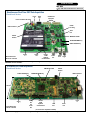
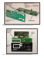
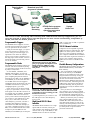
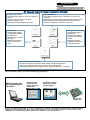
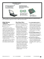
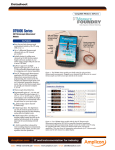
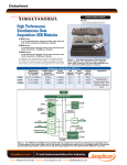
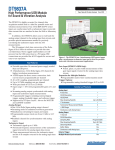
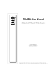
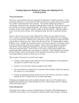
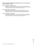
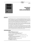
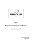
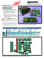
w! DT9840 Series DT9840 Series Ne on rsi e V ut p n EI IEP BUS: USB Type: DSP Real-Time Measurement and Control Simultaneous Real-Time DSP Data Acquisition DT9841 OEM Version DT9841 Noise and Vibration Applications — Eight 24-bit inputs with built-in anti-aliasing filters for superior AC performance. DT9842 Fast Control Loop Applications — Eight high-speed inputs and 2 or 8 precision outputs.. DT9841E Economical Vibration Applications — Economical 2-channel version with built-in antialiasing filters. Available start-up kit is ideal for developers and OEMs. Sleek Box Version DT9841-VIB IEPE for Accelerometers and Microphones w! Ne — Eight IEPE sensor connections. Ideal for noise, vibration, acoustics, sonar, and accelerometer measurements. In addition to the simultaneous input channels, all modules feature two or eight deglitched waveform analog outputs, 24 digital I/O lines (16 on the -VIB version), three 32-bit user counter/timers, and the Texas Instruments 300MHz TMS320C6713 DSP chip. DT9841E Low Cost, 2-Channel OEM Version Figure 1. DT9840 Series modules are available in two configurations: Sleek Box and board-level OEM version and offer a variety of analog input and output options, including IEPE sensor inputs. All modules are fully isolated to 500V. Real-Time DSP Data Acquisition Simultaneous A/D Throughput per Channel A/D Converter Type D/A Channels @500 kHz Counter/ Timers DIO Lines Signal-toNoise Ratio DT9841 8 ch @ 100kHz Sigma-Delta 2 3 24 100dB DT9842 8 ch @ 100kHz SAR 2 or 8 3 24 86dB DT9841E 2 ch @ 100kHz Sigma-Delta 2 3 24 100dB DT9841-V VIB 8 ch @ 100kHz Sigma-Delta 2 3 16 100dB Programmable Clock Clock and Trigger BNCs 2 or 8 SS&H Analog Inputs 500 Volt Isolation Barrier 2 or 8 Analog-to-Digital Converters* USB 2.0 Interface Ext Power +5 V @ 6 A Noise and Vibration, Biomedical, Fast Control Loops, Automotive Test, Acoustics/Sonar, Modal Analysis, Rotating Machinery 2 or 8 DACs 2 or 8 Digital-to-Analog Converters* 32M x 32 SDRAM FPGA TMS320C6713 300MHz DSP Isolated DC - DC FIFO 16/24 Lines DIO and 3 Counter/ Timers Applications 16-Bit Scalable Bus Port 16-Bit Scalable Bus Port 1M x 16 FLASH RAM 14-Pin JTAG 9-Pin Serial Port 1 Figure 2. The DT9840 Series is an intelligent data acquisition system optimized for the highest performance, real-time data acquisition and digital signal processing applications. A unique architecture tightly couples A/D and D/A converters to a DSP engine to allow simultaneous data collection and analysis, and host communications. DT9840 Series BUS: USB Type: DSP Real-Time Measurement and Control Simultaneous Real-Time DSP Data Acquisition Board-Level Version Power In Serial Port Scalable Bus Expansion Power and Status LED 8 LEDs for debug USB 2.0 Interface JTAG Port 500 Volt Isolation TMS320C6713 DSP 128 MB SDRAM Memory 2 MB FLASH Memory Analog In Board Dimensions 233.35 mm x 220 mm Analog Out DIO & 3 32-Bit Up/Down Counter/Timers Power Out Ext. Clock Ext. Trigger Figure 3. This figure shows the component layout and subsystem access of the board-level version of the DT9840 Series module. 2-Channel DSP Data Acquisition Board-Level Version 2 MB FLASH Memory TMS320C6713 DSP 500 Volt Isolation 128 MB SDRAM Memory USB 2.0 Interface 100 mm Analog In Board Dimensions 280 mm x 100 mm Analog Out and Power Out DIO & 3 32-Bit Up/Down Counter/Timers Power In JTAG Port Serial Port ( I/O Connectors compatible to DT9841) Figure 4. This figure shows the component layout and subsystem access of the 2-Channel DT9841E module. EP344 cables connect the DT9841E module to the EP358E accessory panel DT9841E-DK Developer’s Kit Includes: — DT9841E module — Standard USB cable — EP358E accessory panel — EP348 power supply — 2 EP344 cables EP358E accessory panel allows easy signal connections DT9841E provides a low cost solution for OEMs Figure 5. The DT9841E-DK is a startup kit for developers that allows easy signal connections. It consists of the DT9841E board, EP358E accessory panel, 2 EP344 cables, a standard USB cable, and a EP348 power supply. Eight input channel amplifiers/filters for precision IEPE excitation and AC coupling 2 24-bit SigmaDelta analog outputs IEPE compatible 4mA analog inputs Figure 6. Exploded view of the DT9841-VIB, IEPE compatible vibration measurement Sleek Box. Overview The DT9840 Series is a complete data acquisition system for real-time signal capture and processing. With a variety of I/O and programming options, the DT9840 Series provides an ideal platform for real-time applications. Four Different Models and the DT9841E and single-ended mode on the DT9841-VIB, and support an input range of +/-10 V. The DT9842/2 and DT9842/8 modules offer 8, 16-bit analog input channels (without filtering) for fast controlloop applications, such as predictive maintenance and servo loop applica- Simultaneous A/D up to 100kHz per Channel Included in the series are: DT9841 DT9841E DT9841-VIB DT9842/2 and DT9842/8 Each module contains an embedded DSP processor for real-time control and a high-speed USB 2.0 interface for communicating to a host PC. The DT9841, DT9841E, and DT9841-VIB modules feature 24-bit Sigma-Delta converters great for noise and vibration testing. The DT9842/2 and DT9842/8 modules feature 16-bit successive-approximation converters - great for fast control loop operations. Modules provide simultaneous acquisition and control of up to 8 analog input channels (2 on the DT9841E), 2 analog output channels (8 on the DT9842/8), 16 or 24 digital I/O lines, and 3 32-bit counter/timer channels at up to 100 kHz. Additionally, the DT9841-VIB accepts signals from IEPE sensors. And, if you need more I/O, simply connect up to eight DT9840 Series modules together! Two packaging configurations are available for most models to suit your application needs. Software Flexibility To get up and running quickly, use the DT Dynamic Signal Analyzer application to stream real-time data between the PC and your DT9840 Series module right out of the box - without programming! You can modify this application as you wish or configure a complete real-time system using the property pages of Measure Foundry. Or, if you need more flexibility, develop your own low-level DSP application using TI Code Composer Studio. Use DT-LV Link/RTStreaming (DT-LS) to access the power of the DSP through LabVIEW or DTxEZ/RT-Streaming (DT-XS) for easy-touse visual programming tools to access the DSP through VB, C++, VB.NET, C++.NET, or C#.NET. Select the software solution that's right for you! Simultaneous Analog Inputs The DT9841 and DT9841-VIB modules offer 8, 24-bit analog input channels. The DT9841E offers 2, 24-bit analog input channels. These modules have built-in anti-aliasing filters for superior AC performance in noise and vibration testing applications. The analog input channels are configured for differential mode on the DT9841 WWW.DATATRANSLATION .COM Analog In 24-bit A/D data conversion across the full input range. Because of their inherent filtering algorithms, though, Sigma-Delta converters also have an initial delay of 37 clock pulses (370 µs at 100 kHz) after the sample clock is first started and before the first conversion is completed. Thereafter, the data is converted without delay (at 100 kHz, sampling occurs every 10 µs). In fast control-loop applications, this initial delay is unacceptable. For these applications, successive-approximation converters are the best choice. Successive-approximation converters 2 or 8 Sigma-Delta Converters Analog In Simultaneous A/D up to 100kHz per Channel 24-bit A/D Figure 7. Simultaneous Sigma-Delta A/D converters. For each input signal provide high SNR and prevent aliasing. tions. All analog input channels are configured for single-ended mode and support an input range of +/-10 V. When clocked by either the internal or external clock, all analog input channels, digital input lines, and counter/timer channels are simultaneously sampled at up to 100 kSamples/s (800 kHz aggregate). Using software, you can scan all the analog inputs either a specified number of times or continuously. You can also read a single value from a single input channel, if desired. Internally, the DT9841, DT9841E, and DT9841-VIB modules use a SigmaDelta converter for each analog input, while the DT9842/2 and DT9842/8 modules use a successive-approximation converter for each analog input. Sigma-Delta converters offer the following advantages for analog input operations, making them ideal for noise and vibration testing applications: Reduce noise and improve accuracy by oversampling each input up to 64 times. Eliminate errors that result from aliasing and high frequency noise by using a built-in decimation filter when sampling between 200 Hz and 5 kHz. Provide excellent low-level signal-tonoise performance, which improves dynamic accuracy on low-level signals. Provide excellent differential linearity, which ensures consistently accurate US & CANADA (800) 525-8528 Analog In 8 Sucessive Approximation Register (SAR) Converters Analog In 16-bit A/D 16-bit A/D Figure 8. Fast real-time control loops use the successive approximation technique in the DT9842. always run as fast as possible because no filtering is performed (at 100 kHz, sampling occurs every 10 µs). In addition, they have extremely low aperture uncertainty (5 ns jitter) for minimal phase error and very accurate comparison/correlation of high-speed analog signals. Analog Inputs with IEPE Functions Applications that require accelerometer, vibration, noise, or sonar measurements often use IEPE sensors. The DT9841VIB module supports the following software programmable IEPE functions for each of it’s eight analog inputs. Current source — Enable or disable the use of a 4 mA current source to drive the accelerometer. AC/DC coupling — Select whether AC coupling or DC coupling is used. Filtering — Enable or disable the use of the 2-pole, 10kHz, Butterworth filter. GERMANY (49) 7142 95310 UK (44) 1256 333330 4 Waveform Quality Analog Outputs High-Speed Digital I/O Lines The DT9841, DT9841E, and DT9841VIB modules support two, 24-bit waveform analog outputs with an output range of ±10 V or ±2.5 V. A softwareselectable filter of 5 kHz or 20 kHz is available for each channel for smoothing the output value. The DT9842/2 module supports two, 16-bit waveform analog outputs and the DT9842/8 module supports eight, 16bit waveform analog outputs. Each analog output channel provides an output range of ±10 V. Each analog output is deglitched to less than 10 nV second spike for all the major and minor bit carries. The DT9841-VIB module supports two 8-bit digital I/O ports (16 lines). All other DT9840 Series modules feature three 8-bit ports (24 lines) you can program these ports for digital input or digital output operations using software. Interrupt-on-change is also supported for the first port. This feature is useful when you want to monitor critical signals or when you want to signal the host computer to transfer data to or from the module. You can also enable deglitching circuitry on this port to prevent situations where multiple interrupts can occur for one state change. 16 or 24-Bit D/A Analog Out } 24 DIO 3, 32-Bit 8 DI or DO 8 DI or DO 8 DI or DO C/T DIO DIO DIO 2 or 8 16 or 24-Bit D/A Analog Out Output Clock Up to 100kHz Figure 9. Smooth analog outputs with deglitched transitions allow very accurate waveform generation. When clocked by either the internal or external clock, all the analog outputs and digital outputs are simultaneously updated at up to 100 kSamples/s (200 kHz or 800 kHz aggregate). Using software, you can update all the analog outputs either a specified number of times or continuously. You can also generate a waveform for each analog output channel or write a single value to a single output channel, if you wish. Internally, the DT9841, DT9841E, and DT9841-VIB modules use independent Sigma-Delta converters for each analog output channel. At frequencies between 200 Hz and 5 kHz, the Sigma-Delta converters automatically interpolate between data points to eliminate any aliasing effects on the output signals. This interpolation results in a glitch-free transition. The DT9842/2 and DT9842/8 modules, in contrast, use successiveapproximation converters for unfiltered outputs with fast response times. Figure 10. The DT9841-VIB contains 16 DIO lines while all other models contain 24 DIO lines. All models have 3, 32-bit counter/timers. When clocked by either the internal or external clock, all the digital input lines, analog input channels, and counter/timer channels are simultaneously sampled at up to 100 kSamples/s. At the same time, all the digital output lines and analog output channels are updated at the same clock rate. Using software, you can read all the digital input lines or update all the digital output lines either a specified number of times or continuously. You can also read a single value from a single digital input line or update a single digital output line, if you wish. On power up or reset, no digital data is output from the modules. All the outputs include diode protection to the isolated ground and the isolated +5 V. Up/Down Counter/Timers All DT9840 Series modules provide .three 32-bit counter/timer channels with programmable C/T clocks, gates, edges, and pulse output parameters. You can use these counter/timers to perform standard counting operations, such as event counting and rate generation, as well as up/down counting, one-shot, and repetitive one-shot operations. Additionally, you can measure the period or frequency of a signal between programmable clock or gate edges. You can also read the value of all the counter/timer channels at the same time as the analog input channels and digital input lines at up to 100 kHz. Easy Channel Expansion For high-channel count applications, use the Scalable Bus connectors on the module and the shielded EP342 cable to connect up to eight modules together for up to 64 analog I/O channels, 192 digital I/O lines, and 24 counter/timer channels. (Expansion capability is available on the DT9841, DT9841-VIB, and DT9842). If you wish, you can synchronize the operation of all modules using the Scalable Bus master clock. In this configuration, one module is the master and the other modules are slaves. You can use either an internal or external clock source to pace the master module. The Scalable Bus master clock resets the slave modules and paces them at the same rate as the master module. The first and last modules in the chain must be terminated with software-selectable 100 Ohm termination resistors. Figure 11. Up to 8 Sleek Boxes can be configured for high channel count systems. Running Host Program Download your DSP program to onboard memory USB Real-Time Streaming DT9840 Series program performs real-time operations on system under test System Under Test Figure 12. Download your DSP program to SDRAM memory on the DT9840 Series module. The module can then run on its own, monitoring and controlling data. With the Flash memory configuration, you can store this program in Flash memory. The DSP program can then restart automatically, independent of the PC, each time the module powers on. Programmable Triggers The DT9840 Series supports an internal and external trigger for starting all the I/O operations on the module. Using the internal trigger, I/O operations start based on a software command. Using an external trigger, I/O operations start when the module detects a low-to-high transition on the Ext Trig input of the module. Connect a TTL-level signal to the Ext Trig connector on the module. Programmable Clocks All DT9840 Series modules support an internal and external clock for pacing I/O operations. These clocks are shared by all I/O subsystems. On the DT9841, DT9841E, and DT9841-VIB modules, the internal clock has a 36 MHz time base and supports sampling frequencies between 200 Hz and 100 kHz. On the DT9842/2 and DT9842/8, the internal clock has an 18 MHz time base and supports sampling frequencies between 0 Hz and 100 kHz. Use software to specify the sampling frequency you want. If you want to use an external clock to pace I/O operations, connect a TTLlevel signal to the Ext Clk connector on the module. For the DT9841, DT9841E, and DT9841-VIB ensure that the frequency of the external clock signal that you connect to the module has a 50% duty cycle, is 256 times the actual clock frequency you want, and has a resulting clock frequency between 200 Hz and 100 kHz. For example, if you need a sampling frequency of 100 kHz, use an external clock source with a frequency of 25.6 MHz. For the DT9842/2 and DT9842/8, the frequen- WWW.DATATRANSLATION .COM USB 1.1 ports, but at USB 1.1 performance (12 Mbits/s). 500 V Galvanic Isolation Figure 13. Removable side panel allows direct access to the JTAG port for program development and debug purposes. LEDs are also viewable for debugging through this panel. Figure 14. The EP348 power supply is included with the Sleek Box and is available as an accessory for the board-level version. cy of the signal that you connect to the Ext Clk input is the clock frequency that is used. High-Speed USB 2.0 Host Interface All DT9840 Series modules use a highspeed USB 2.0 interface, which provides transfer rates between the module and the host at up to 480 Mbits/s. The DT9840 Series can also be used with US & CANADA (800) 525-8528 Computers are susceptible to groundspikes through any external port. These spikes can cause system crashes and may even cause permanent damage to your computer. DT9840 Series modules feature 500 Volts of galvanic isolation to protect your computer from groundspikes and to ensure a reliable stream of data. Flexible Memory Configurations All DT9840 Series modules provide 128 MB of SDRAM memory and 2 MB of flash memory. You can download a DSP program from the PC directly to the SDRAM memory on the module and run it. The program resides in memory as long as the module stays powered on. The module does not need host intervention (eliminating any Windows latencies) and can run on its own, monitoring and controlling data. If the PC becomes disconnected accidentally, data is preserved, ensuring the security of mission-critical applications. Once you have run and debugged your program, you can store it in flash memory. This allows the DSP program to run automatically, independent of the PC, each time the module is powered on. Memory is shared by the I/O subsystems, onboard DSP processor, and Scalable Bus. Each subsystem has its own high-speed pathway in and out of memory, and each pathway has its own independent DMA controller. This allows I/O subsystems to operate without processor intervention. GERMANY (49) 7142 95310 UK (44) 1256 333330 6 DT9840 Series BUS: USB Type: DSP Real-Time Measurement and Control DT Dynamic Signal Analyzer Application Example Oscilloscope Panel: Spectrum Panel: Stream and analyze signals on one or all 8 channels in real-time Zoom/pan, autoscale, or freeze live signals Print or save signals to disk Open and post-analyze saved signal from disk Stream data in and perform up to a 128K point FFT on one or all 8 channels Many FFT types: spectrum analyzer, autocorrelation, power spectrum Many windows functions, including Rectangle, Hann, Blackman Select linear, logarithmic, or dB view for Y-axis scale DVM Panel: Configuration Panel: 24-bit resolution provides 6.5-digit Digital Volt Meter for all 8 channels Selectable upper- and lowerlimit range Warning LED indicator for values in or out of limit range Automatically configures DT9840 Series Selectable input sampling frequency from 10 kHz to 100 kHz Selectable input audio sampling frequencies from 11.025 kHz to 96 kHz Function Generator Panel: Generate DC, Sine Wave, Square Wave, Ramp, Triangle, and Arbitrary Waveforms Set frequency, amplitude, offset, duty cycle, sweep rate, and sweep width Load and play standard waveform signals from file (supports all .WAV, .DCF, or ASCII files) Figure 15. The DT Dynamic Signal Analyzer automatically configures DT9840 Series hardware for realtime streaming to/from a host PC without programming! DT Measure Foundry/ Measure Foundry is an RT-Streaming open, powerful applicaPoint-and-Click tion builder ... Program Development Drag and drop instrument-like panels onto your worksheet ... Configure real-time tasks using simple property pages ... USB ... and you are ready to run. Figure 16. Measure Foundry is a user configurable, real-time development package that makes developing applications simple and fast. Using property pages you can easily configure real-time tasks. The COFF file is automatically downloaded to the module in the background. Code-Based Program Development Develop host program with C++ or Visual Basic and Data Translation Host Communication library. Develop DSP program with TI Code Composer Studio and Data Translation DSP libraries. USB DT_BoardDownload( BRD_HANDLE hBoard, CHAR *pFilename, BOOL bVerifyFlag); DT_ReadADC( ULONG nADCIndex LONG *pADValue(; Figure 17. For maximum flexibility, you can develop your own low-level DSP applications using TI Code Composer Studio. You can develop DSP programs to run in stand-alone mode or to communicate with your own Windows application written in Microsoft Visual Studio. Multiple Packaging Configurations Many Software Choices DT9840 Series modules are available in two packaging configurations: Sleek Box version (-SB). Board-level version. The Sleek Box for the DT9841, DT9841-VIB, and DT9842 packages the board-level version of the DT9840 Series module in a CE-compliant box with standard signal connectors, USB cable, power supply (EP348), and fan. This configuration is great for easy signal connections. A removable side panel allows direct access to the JTAG connector for debugging purposes. The Sleek Box is not available for the DT9841E. However, a developer’s kit is available for the DT9841E. The DT9841-VIB has a special interface board designed specifically for IEPE sensor inputs. The board-level version is available for OEM embedded applications, and ships with a USB cable. A +5 V AC to DC power supply is required for operation, and is available separately as EP348. WWW.DATATRANSLATION .COM A number of software choices are provided to allow users of all levels - from programmers to application users - the ability to access the DT9840 Series: Measure Foundry is an open powerful application builder for test and measurement systems. Using property pages, you can easily configure real-time tasks like data collection, data display, signal processing, and streaming to disk. Programming blocks support custom algorithm development. Measure Foundry is also MATLAB® and Excel® compatible. Measure Foundry automatically downloads the required COFF files to the module in the background. The DT Dynamic Signal Analyzer helps you to get up and running quickly. You can stream real-time data between the PC and your DT9840 Series module right out of the box! The DT Dynamic Signal Analyzer is a Ready-to-MeasureTM application that automatically configures the DT9840 Series hardware, performs oscilloscope, spectrum analyzer, digital voltmeter, and function generator operations, and streams data to and from the host PC - all without programming! You can modify this application as you wish or configure a complete real-time system using Measure Foundry. US & CANADA (800) 525-8528 Use TI Code Composer Studio for maximum flexibility. Using Code Composer, you can develop your own low-level DSP applications to run in stand-alone mode or to communicate with your own Windows application written in Microsoft Visual Studio. Each DT9840 Series module comes with a device driver, a full set of I/O and communication API libraries for the DSP and host PC, example programs and utilities, and complete documentation. DT-LV Link/RT-Streaming (DT-LS) provides a collection of Virtual Instruments (VIs) that give programmers the ability to access the power of the DSP through LabVIEW. Use VIs to stream data from any DT9840 Series module in real-time. DT-EZ/RT-Streaming(DT-XS) provides easy-to-use visual programming tools that let programmers stream data from any DT9840 Series DSP module in real-time using Microsoft Visual Basic, Visual C++, Visual Basic.NET, Visual C++.NET, or Visual C#.NET. GERMANY (49) 7142 95310 UK (44) 1256 333330 8 DT9840 Series BUS: USB Type: DSP Real-Time Measurement and Control Easy Signal Connections DT9840 Series Documentation The Sleek Box version of the module, shown in Figure 1, provides BNCs for all the analog I/O, external trigger, and external clock signals. You can also access the analog I/O and digital I/O signals through 37-pin D-sub connectors on the front panel. A 25-pin D-sub connector is provided on the front panel for accessing the counter/timer signals. The following manuals are shipped on the CD-ROM supplied with the DT9840 Series module: The board-level version of the module, shown in Figure 1, provides two 68-pin connectors for accessing all of the analog I/O, digital I/O, and counter/timer signals, and BNCs for attaching external trigger and clock signals. The 8-channel versions of the module also provide Scalable Bus connectors for attaching up to 7 additional modules, a serial port connector and JTAG connector for easy debugging, a power input and output connector, and a USB 2.0 connector for attaching to a host computer. The DT9841E offers a startup kit for developers to allow easy access to all signal connections. The DT9841E-DK consists of the DT9841E board, EP358E accessory panel, 2 EP344 cables, standard USB cable, and an EP348 power supply. The DT9841-VIB provides BNC inputs on the front panel specifically designed to accept inputs from IEPE sensors. Additionally, a separate BNC is provided for x, y, z positioning. Getting started manual - Describes how to install and set up a module and verify that it is working properly. User's manual - Describes the hardware features of the modules. DSP library manual - Describes the I/O and communication API libraries that are provided for programming the DSP on the module with Code Composer Studio. Host communication library manual Describes the Windows library for the host that is provided for communicating with a DT9840 Series module using Microsoft Visual Studio. Technical Support As you develop your application, application engineers are available during normal business hours to discuss your requirements. Extensive information is available 24 hours a day on our web site at www.datatranslation.com, including drivers, example code, pin assignments, a searchable KnowledgeBase, and much more. Support is also available from your point of purchase. Telephone support is free for the first 90 days; you can also request support via email or fax during this time. After the initial 90 day period, a small fee is charged for additional support. Ordering Summary Accessories (Sold Separately) Each DT9840 Series module is shipped with a USB cable, device drivers for Microsoft Windows 2000/XP, DSP library, host communication library, and comprehensive manuals in PDF form. Manuals are available in hard-copy form for an additional charge. The Sleek Box version also ships with the EP348 power supply. The following accessories are available: EP342 — 0.1m shielded 50-pin cable for con- necting multiple DT9840 Series modules using the Scalable Bus. EP348 — +5V optional power supply (with includ- ed power cable). EP354 — RS-232 adapter converts serial output to standard RS-232. EP358E — 2 channel in, 2 channel out accessory panel for DT9841E; includes 2 EP344 cables. Supported Software DT Dynamic Signal Analyzer application example Measure Foundry/RT-Streaming DT-LV Link/RT-Streaming (DT-LS) DTx-EZ/RT-Streaming (DT-XS) TI Code Composer (3.0 or 3.1) Microsoft Visual Studio (6.0 or greater) System Requirements Windows 2000 (with Service Pack 4) or Windows XP Professional Edition (with Service Pack 1) USB Ports — one or more (version 2.0 or 1.1) Click here for full specifications Click here for pin assignments © Copyright 2006 Data Translation, Inc. All rights reserved. All trademarks are the property of their respective holders. Prices, availability, and specifications subject to change without notice. 03/2007 Module Ordering Summary Model Number Analog Inputs A/D Converter Resolution Analog Outputs Packaging Configuration DT9841 8 DI Sigma-Delta 24 bit 2 Board-level version DT9841E 2 DI Sigma-Delta 24-bit 2 Board-level version DT9841E-DK 2 DI Sigma-Delta 24-bit 2 Developer’s Kit DT9841-SB 8 DI Sigma-Delta 24-bit 2 Sleek Box version DT9841-VIB-SB 8 SE Sigma-Delta 24-bit 2 Sleek Box version DT9842/2 8 SE Successive-Approximation 16-bit 2 Board-level version DT9842/2-SB 8 SE Successive-Approximation 16-bit 2 Sleek Box version DT9842/8 8 SE Successive-Approximation 16-bit 8 Board-level version DT9842/8-SB 8 SE Successive-Approximation 16-bit 8 Sleek Box version