1
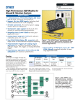
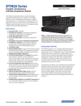
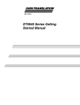
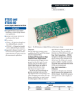
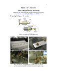
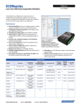
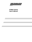
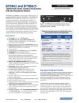
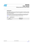
DT9837A DT9837A High Performance USB Module for Sound & Vibration Analysis Type: Noise & Vibration Analysis The DT9837A is highly accurate five channel data acquisition module that is a ideal for portable noise and vibration measurements. Four 24-bit IEPE (ICP®) sensor inputs are synchronized with a tachometer input to provide data streams that are matched in time for field or laboratory use. In addition, the DT9837A allows you to read back the analog output channel in the analog input data stream, and provides special measurement modes for precisely correlating the tachometer input with the A/D measurements. The 38 segment clock-time conversion of the DeltaSigma A/Ds is of fset in software to provide this time correlated data. These rugged small modules are selfpowered via the USB connection to a PC laptop. BNC connections are provided for all I/O signals for secure and easy-to-use operation. Key Features Portable operation. No external power supply needed. Runs on USB power. ■ 4 Simultaneous, 24-bit Delta-Sigma A/D channels for highest resolution measurements ■ 4 IEPE inputs for direct sensor connection; 4mA current source programmable per channel ■ AC or DC coupling, programmable per channel ■ Up to 52.7kHz sampling rate per channel ■ Wide pass band of 0.5 Hz to 25.8 kHz ■ Input range +/-10V with programmable gains of 1 and 10 ■ Streaming analog output synchronized with analog input and tachometer input measurements ■ Programmable triggers including external digital trigger, analog threshold trigger, and software trigger ■ Supported by DT-Open Layers... drivers for MATLAB and LabVIEW available Analog Output: ■ One 24-bit Delta-Sigma analog output channel ■ Streaming mode for unlimited waveform generation ■ Simultaneous streaming for inputs and output ■ Programmable output clock rate from 10 kHz to 52.7 kHz ■ Readback channel for synchronization with analog inputs Tachometer Input: ■ Tachometer signal up to 1 MHz ■ Period and frequency measurements of the tachometer signal returned in the analog input data stream ■ Phase measurements between the tachometer input and the A/D samples returned in the analog input data stream ■ WWW.DATATRANSLATION.COM US/CANADA (800) 525-8528 Bus: USB Figure 1. The DT9837A has 4 simultaneous IEPE sensor inputs plus a synchronous tachometer input and is ideal for portable noise and vibration measurement applications. Gate Input (DT9837A-OEM Only): ■ Period, phase, or pulse width measurements of the gate input signal returned in the analog input data stream Expansion for Multiple Modules: ■ Programmable master/slave synchronization mode Trigger Options: ■ Programmable analog threshold trigger 0.2V to 9.8V Summary of Features Analog Input 4 Channels 24-Bit Resolution AC/DC/4mA Max Sampling Rate/Ch. 1 Tachometer Tachometer Measurement Modes +/-30V Range Simultaneous with Analog Output Analog Output 1 Channel 24-Bit Resolution Sampling Rate Max Sampling Rate/Ch. Streaming Mode Buffer Mode Simultaneous with Analog Input External Trigger Multiple Module Synchronization EUROPE/ASIA +49 (0) 7142-9531–0 Up to 52.7kHz 3 Programmable Up to 52.7 kHz Yes Yes Yes Yes 4 Analog Inputs with BNC Connections 4, 24-Bit Delta-Sigma A/Ds with IEPE Conditioning Powered on High-Speed USB 2..0 Status light 24-Bit Analog Signal Output External Trigger Board Dimensions: Tachometer Input Channel 146mm x 100mm Figure 2. An OEM, board-level version of the DT9837A is available (DT9837A-OEM). These modules provide BNC connectors for easy signal connections. The DT9837A-OEM provides an additional gate input connector for precisely correlating analog input and gate input measurements. Exploded View Top Panel Marked for easy signal connection DT9837A Board CE-Compliant Enclosure Maintains signal integrity Figure 3. The DT9837A board is encased in a rugged, metal enclosure to ensure CE-compliance and maintain signal integrity. WWW.DATATRANSLATION.COM US/CANADA (800) 525-8528 EUROPE/ASIA +49 (0) 7142-9531–0 2 Block Diagram of the DT9837A Module ± 18 V Compliance Voltage 4 mA Current Source Sigma-Deltas 24-Bit A/D 1M Analog Input 0 D/A FIFO x1, 10 4 mA A/D FIFO 24-Bit A/D 1M Analog Input 1 x1, 10 Control Logic 4 mA HighSpeed USB 2.0 Interface USB 2.0 A/D Clock 24-Bit A/D 1M Analog Input 2 x1, 10 Ext Trigger and Clock RJ45 4 mA 24-Bit A/D Analog Input 3 1M x1, 10 D/A Clock D/A Output 0 24-Bit D/A SigmaDelta 10 kHz Filter Trigger D/A Readback 16-bit A/D Ext Trigger Tachometer Input Figure 4. The block diagram above shows the readback of the D/A output in the analog input data stream to allow all data to be synchronized in one data stream. The 24-bit Delta-Sigma A/D with D/A readback allows precise time correlation between D/A output and all analog inputs. WWW.DATATRANSLATION.COM US/CANADA (800) 525-8528 EUROPE/ASIA +49 (0) 7142-9531–0 3 Analog Inputs The DT9837A module supports four analog input channels and a tachometer input. Gains of 1 and 10 are supported for ef fective input ranges of +/- 10V and + /- 1V. The module uses 24-bit Delta-Sigma analog-to-digital converters (ADCs) that provide anti-aliasing filters based on the clock rate. These filters eliminate aliasing, which is a condition where high frequency input components erroneously appear as lower frequencies after sampling. You can read data from one or more analog input channels using an analog input channel list. You can enter up to 8 entries in the channel list. These include: ■ Four analog input channels ■ Tachometer counter 0 for period or frequency measurements on the tachometer input signal ■ Tachometer counter 1 for phase measurements between A/D samples and the tachometer to correlate analog input and tachometer measurements ■ On the DT9837A-OEM module only, gate counter 2 for period, frequency, or phase measurements between A/D samples and the gate input to correlate analog input and gate measurements Simultaneous A/D Up to 52.734 kHz per Channel Analog In 24-bit A/D 4 Delta-Sigma Converters Analog In 24-bit A/D Tachometer Input Analog Inputs with IEPE Functions Applications requiring accelerometers, vibration, noise, and sonar measurements often use IEPE sensors. The DT9837A module supports the following software programmable IEPE functions for each of the four analog inputs: ■ Current source ‒ Enable or disable the use of a 4mA current source to drive the IEPE sensors. ■ AC/DC coupling ‒ Select whether AC coupling or DC coupling is used. Break detection is provided if using DC coupling with the 4mA excitation current source and the voltage input is positive, full-scale. Delta-Sigma A/D Converters The DT9837A module has built-in anti-aliasing filters for superior AC performance in noise and vibration testing applications. Internally, the DT9837A module uses a Delta-Sigma converter for each analog input Delta-Sigma converters of fer the following advantages for analog input operations, making them ideal for noise and vibration testing applications. ■ Reduce noise and improve accuracy by oversampling each input. ■ Eliminate errors that result from aliasing and high frequency noise. ■ Provide excellent low-level signal-to-noise performance, which improves dynamic accuracy on low-level signals. ■ Provide excellent dif ferential linearity, which ensures consistently accurate data conversion across the full input range. WWW.DATATRANSLATION.COM US/CANADA (800) 525-8528 Figure 5. Simultaneous Delta-Sigma A/D converters and the tachometer input are synchronized through software to accommodate for the group delay of the A/D converters. Group Delay and Data Synchronization Because of the inherent filtering algorithms, Delta-Sigma converters have an initial delay of 38 clock pulses after the sample clock is first started and before the first conversion is completed, due to the group delay of converters. The tachometer data (which does not have the 38 sample group delay) is synchronized with the analog data stream. This is done through the firmware and device driver by caching the tachometer data and aligning it in time with the analog data in the userʼs data buf fers. Tachometer Input – Counter 0 The DT9837A includes support for a tachometer input in the analog input data stream for precise frequency measurements. The module accepts one ±30V, 31-bit tachometer input signal. This signal has a maximum frequency of 1MHz and a minimum pulse width of 0.4 microseconds. The threshold voltage is fixed at ±2V with 0.5V of hysteresis. Measurements are based on two consecutive edges (either rising or falling) of the tachometer input signals and is based on a 12 MHz clock frequency (with a resolution of 83 ns). The tachometer input is treated like any other channel in the analog input channel list; therefore, all the clocking, triggering, and conversion modes supported for analog input channels are supported for the tachometer input. EUROPE/ASIA +49 (0) 7142-9531–0 4 Correlating A/D and Tachometer Measurements Figure 6. By connecting a rotating device to the tachometer input of the DT9837A, you can measure the frequency or period of the rotating device. The DT9837A also provides the ability to accurately measure the time between the tachometer edge and the next A/D sample or between the A/D sample and the next tachometer edge, so that you can precisely correlate A/D data with rotation data. For example, assume that you want to correlate A/D sample X from analog channel 0 to an angular position of the rotating device. This can be accomplished by using a tachometer signal that always occurs at the top, center position of the rotating device as a reference and measuring the time between the tachometer signal and the next A/D sample (Y). Since you know the frequency of the A/D sample clock (50 kHz, in this case), you know when A/D sample X occurred in relation to A/D sample Y (t2 = 1/50kHz x num samples from Y to X). By using the Tachometer Counter 1 to measure the time (t1) between the tachometer signal and A/D sample Y, you can calculate exactly where A/D sample X occurred in time from the tachometer signal (result = t1 + t2). Given the rotation speed of Tachometer Counter 0, you can then calculate the angular position of A/D sample X. WWW.DATATRANSLATION.COM US/CANADA (800) 525-8528 EUROPE/ASIA +49 (0) 7142-9531–0 5 0dB - 3dB single pole - 6dB per octave rolloff -3dB@ .49 x Sampling Frequency (Eliminate Nyquist Aliases) Wide Band Pass - 3dB Near 0 Ripple in Pass Band (Linear Phase) AMPLITUDE Built-In Digital Filter Provides Brick Wall Roll Off Figure 7. The DT9837A provides software selectable AC and DC coupling. When AC coupling is selected, the modules provide zero ripple in the wide pass band and excellent “brick wall” anti-alias filters eliminating unwanted high frequency interference. -100dB @.55 x Sampling Frequency 0.5Hz 25.8kHz FREQUENCY Tachometer Input – Counter 1 Synchronous Operation The DT9837A provides tachometer counter 1, which allows you to measure the time from the stopping edge (rising or falling) of the tachometer input signal to the completion of the A/D samples, or the time from the completion of the A/D samples to the stopping edge (rising or falling) of the tachometer input signal. A 48 MHz clock (with a resolution of 21 ns) is used to calculate the measured time. This very precise measurement allows you to accurately correlate the tachometer pulse and IEPE input measurements. The DT9837A supports synchronous analog input, tachometer input, and analog output operations. Data is streamed synchronously to host memory. The synchronous operation allows all I/O data to be processed and correlated for all inputs and outputs. This is very valuable in determining the response across a device-under-test (DUT) to stimuli at the same exact instant. Gate Input – Counter 2 For the DT9837A-OEM module only, you can also measure the time from the A/D sample or gate input signal to the next A/D sample or gate input signal. A 48 MHz clock (with a resolution of 21 ns) signals is used to precisely correlate analog input data with external signals often used in rotation applications. Waveform Quality Analog Output The DT9837A supports one 24-bit D/A converter with an output range of +/- 10V. You can output a single value, a waveform, or a continuous user-defined output signal using a software trigger, external TTL trigger, or analog threshold trigger. A two-pole, 10kHz Butterworth filter is applied to remove clocking noise and smooth the output signal. You can generate any waveform, such as white noise, and send it to the output channel using a clock frequency from 10kHz to 52.734kHz. Great care has been used in design to minimize the glitch energy for any major or minor carry. This results in extremely smooth waveforms. You can update the analog output channel as you are acquiring analog input data for gap-free simultaneous stimulus and response. You can also read back the analog output value in the analog input data stream. Note that since the module uses a Delta-Sigma D/A converter, 29 clock pulses are required before the first D/A conversion is complete. WWW.DATATRANSLATION.COM US/CANADA (800) 525-8528 Synchronization of Multiple Modules DT9837A modules provide an RJ45 (LVDS) synchronization connector for connecting two DT9837A modules together (as shown in figure 8). In this scheme, one module is configured as the master and the other module is configured as the slave. Start the slave first; then start the master. When the master module is triggered (using any of the supported trigger sources), both the master and slave modules start acquiring data at the same time (within one A/D conversation of the clock. Figure 8. A DT9837A Master/Slave component in Measure Foundry allows two modules to operate in perfect synchronization for 8 IEPE inputs and 2 tachometer inputs. EUROPE/ASIA +49 (0) 7142-9531–0 6 Programmable Triggers You can start an analog input or analog output operation using either a software trigger, external TTL trigger, or analog threshold trigger. Using the internal trigger, I/O operations start based on a software command. Using an external trigger, analog I/O operations start when the module detects a low-to-high transition on the EXT TRIG (TTL) input of the module. Using an analog threshold trigger, analog I/O operations start when the module detects a signal on analog input channel 0 that rises above a user defined threshold level of 0.2V to 9.8V. Programmable A/D Clock Figure 9. Measure Foundry allows you to create noise and vibration applications quickly and easily using a drag and drop graphical interface. No programming required. ■ The DT9837A module supports an internal A/D clock with a maximum time base of 27MHz. Using software, you can specify the frequency (from 195.3Hz to 52.734kHz) at which to sample all the input channels. The value that you specify for the internal clock frequency is multiplied by 512 internally to set the oscillator on the module. For example, if you specify an internal clock frequency of 50kHz, the module sets the internal oscillators for the A/D converters to 25.6MHz. To eliminate aliasing, the DT9837A supports a wide pass band of 0.5Hz to 25.8kHz (0.49 x the sampling frequency), allowing you to measure low frequency signals accurately at the Nyquist sampling rate. ■ ■ Store the data to either an ASCII data file or a high performance .DCF file. Provides several window functions: Rectangle, Hanning, Hamming, Hann, Blackman, Blackman Harris 67db or 92 db. Provides digital filter functions including Bessel, Butterworth, Chebyshev, and Elliptic. Software Applet The DT9837A ships with a software applet to get you up and running right out-of-the-box. This applet supports basic operation of the module and can be easily modified for more advanced capabilities using Measure Foundry. Other Software Choices Software Many software choices are available for application development with the DT9837A. Each option of fers development capability at dif ferent levels. Choose from ready-to-measure applications to full graphical programming with Measure Foundry. The DT9837A module ships with the Omni CD that includes the following software: ■ Measure Foundry Measure Foundry is a powerful visual software environment for creating test and measurement, control, and analysis applications. It provides all the power and flexibility of a programming language in a drag and drop graphical interface. No programming or wiring is required! Measure Foundry of fers a specially designed component that allows perfect synchronization of two DT9837A modules. This saves valuable development time as two DT9837A modules in a master/slave configuration are presented in a single component as if they are one device with twice the channels. ■ ■ Measure Foundry features include: ■ ■ ■ Create noise and vibration applications quickly and easily. Spectrum analyzer panel allows you to display and analyze the frequency spectrum of an input signal. Perform an FFT, auto-correlation, or power spectrum on the input signal. WWW.DATATRANSLATION.COM US/CANADA (800) 525-8528 ■ DT-Open Layers for .NET: The DT-Open Layers for .NET Class Library is a collection of classes, methods, properties, and events that provides a programming interface for DT-Open Layers-compatible hardware devices. It can be used from any language that conforms to the Common Language Specification (CLS), including Visual Basic.NET, Visual C#, Visual C++.NET with managed extensions, and Visual J#.NET. DT-Display for .NET: DT-Display for .NET is a control for plotting data to a Windows form. It provides a powerful and user-friendly interface for rendering data. DT-Open Layers for Win32: DT-Open Layers for Win32 consists of the DataAcq SDK. The DataAcq SDK consists of the necessary header files, libraries, example programs, and documentation to develop your own DT-Open Layers data acquisition and control applications. It is intended for use with non .NET languages, such as ANSI C, Visual C++ 6.0, and Visual Basic 6.0. Drivers: The 32-bit WDM device drivers make your application cross-platform compatible. These drivers support Data Translation USB and PCI boards using Windows 2000/XP/Vista. EUROPE/ASIA +49 (0) 7142-9531–0 7 User Manual You can choose to install demo versions of the following software from the CD: ■ ■ ■ Measure Foundry is an open, powerful application builder for test and measurement systems. No programming is required! quickDAQ is a high-performance, ready-to-run application that lets you acquire, plot, analyze, and save data to disk at up to 2 MHz per channel without writing any code. quickDAQ supports applications from temperature measurement to high-speed testing and analysis. LV-Link contains all necessary VIs, examples, and documentation to use Data Translation hardware in LabVIEW 8.0 and higher. Each DT9837A module includes a userʼs manual that provides getting started and reference information about using the DT9837A. The manual is provided in electronic (PDF) format on the Data Acquisition Omni CD provided with the module. Technical Support Application engineers are available by phone and email during normal business hours to discuss your application requirements. Extensive product information, including drivers, example code, pinouts, a searchable Knowledge Base, and much more, is available 24 hours a day on our web site at www.datatranslation.com. The following software is available as a free download from out website: ■ DAQ Adaptor for MATLAB to access the visualization and analysis capabilities of MATLAB from The MathWorksTM. The DT9837A is also supported by third-party noise and vibration analysis applications. USB 2.0 Compatibility The DT9837A module uses a high-speed USB 2.0 interface, which provides transfer rates between the module and the host at up to 480 Mbits/s. This means that all acquired signals stream to and from the host at full acquisition speeds. The DT9837A can also be used with USB 1.1 ports, but at USB 1.1 performance (12 Mbits/s). Easy Signal Connections The DT9837A provides BNCs for the analog input, tachometer input, analog output, and external trigger signals. EMI and ESD Design Criteria The DT9837A has been designed to perform with the lowest noise characteristics. Damping resistors in series with every I/O line minimize ringing and EMI and provide current limits that protect against transient signals. Cross-Series Compatibility Virtually all Data Translation data acquisition boards, including the DT9837A, are compatible with the DT-Open Layers for .NET Class Library. This means that if your application was developed with one of Data Translation's software products, you can easily upgrade to a new Data Translation board. Little or no reprogramming is needed. WWW.DATATRANSLATION.COM US/CANADA (800) 525-8528 EUROPE/ASIA +49 (0) 7142-9531–0 8 Ordering Summary DT9837A – High performance USB module for sound and vibration analysis packaged in a CE-compliant enclosure. ■ DT9837A-OEM – Board-level version of the DT9837A with gate input signal. Accessories: ■ EP342 – RJ45 .1m shielded cable, 50-pin connector Software: The following software can be purchased separately: ■ Measure Foundry – Test and measurement application builder for Windows® XP/Vista. SP1300-CD. ■ quickDAQ – High-performance, readyto-run application that lets you acquire, plot, analyze, and save data to disk at up to 2 MHz per channel. SP8501-CD ■ LV-Link – Access the power of Data Translation boards through LabVIEW™. Free Software Downloads: The following software is available as a free download from our website: ■ DAQ Adaptor for MATLAB – Access the analyzation and visualization tools of MATLAB®. ■ All Data Translation hardware products are covered by a 1-year warranty. For pricing information, see the current price list, visit our website, or contact your local reseller. For more information about the DT9837A, please visit: http://www.datatranslation.com/go/DT9837A/ For specifications, drawings, and pin assignments, please visit: http://www.datatranslation.com/go/DT9837A/techinfo/ Copyright © 2009 Data Translation, Inc. All rights reserved. All trademarks are the property of their respective holders. Prices, availability, and specifications subject to change without notice. Rev 2.0A. WWW.DATATRANSLATION.COM US/CANADA (800) 525-8528 EUROPE/ASIA +49 (0) 7142-9531–0