1
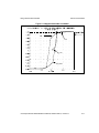
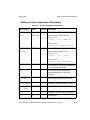
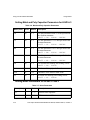
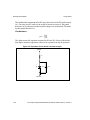
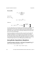
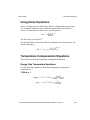
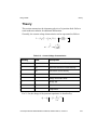
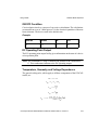
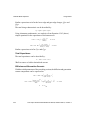
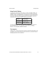
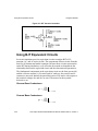
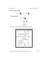
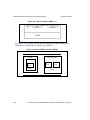
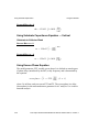
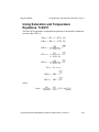
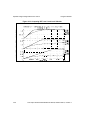
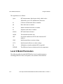
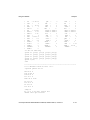
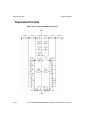
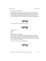
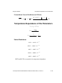
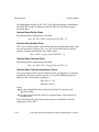
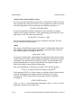
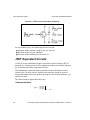
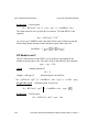
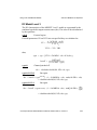
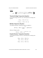
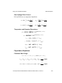
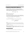
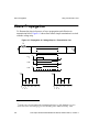
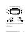
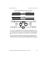
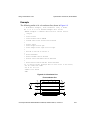
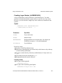
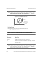
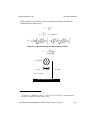
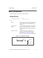
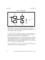
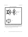
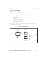
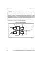
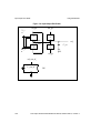
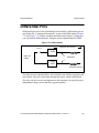
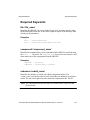
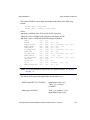
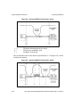
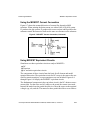
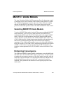
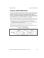
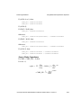
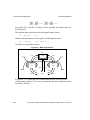
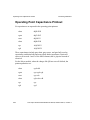
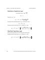
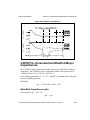
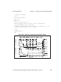
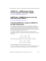
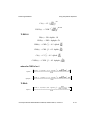
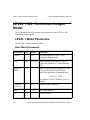
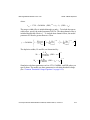
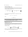
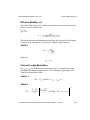
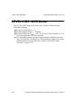
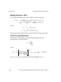
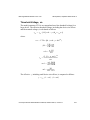
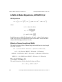
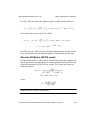
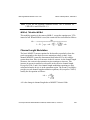
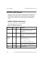
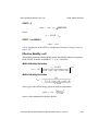
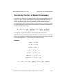
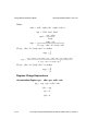
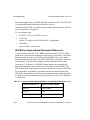
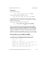
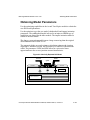
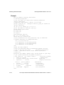
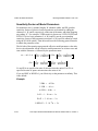
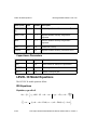
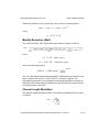
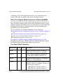
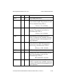
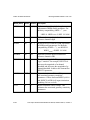
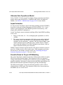
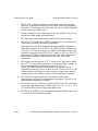
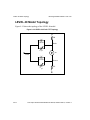
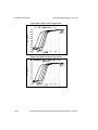
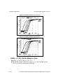
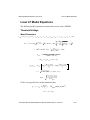
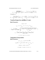
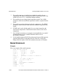
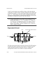
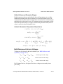
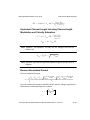
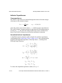
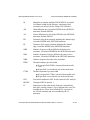
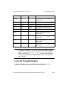
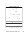
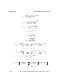
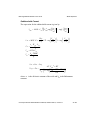
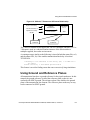
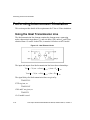
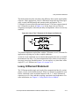
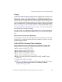
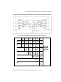
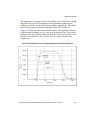
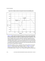
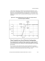
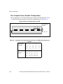
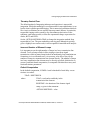
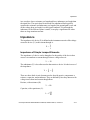
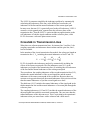
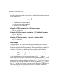
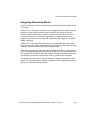
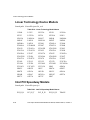
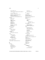
Lossy U Element Statement
The ideal transmission line only delays the difference between the signal and the
reference. Some applications, such as a differential output driving twisted pair
cable, require both differential and common mode propagation. Use a
U Element, if you need the full signal and reference. You can use approximately
two T Elements (as shown in Figure A-6). In this figure, the two lines are
completely uncoupled, so that only the delay and impedance values are correctly
modeled.
Figure A-6: Use of Two T Elements for Full Signal and Reference
out
in
outbar
You cannot implement coupled lines with the T Element, so use U Elements for
applications requiring two or three coupled conductors.
Avant! in-circuit simulation uses a transient timestep that does not exceed half
the minimum line delay. Very short transmission lines (relative to the analysis
time step) cause long simulation times. You can replace very short lines with a
single R, L, or C Element (see Figure A-1 on page A-4).
Lossy U Element Statement
The U Element models single and coupled lossy transmission lines for various
planar, coaxial, and twinlead structures. When a U Element is included in your
netlist, simulation creates an internal network of R, L, C, and G Elements to
represent up to five lines and their coupling capacitances and inductances. For
more information, see Chapter 2, “Using Passive Device Models”.
True-Hspice Device Models Reference Manual, Release 2001.4, revision A
A-11