1
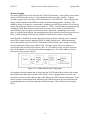
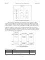
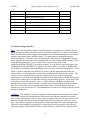
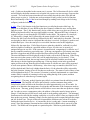
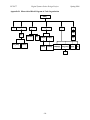
Homework 10: Software Design Considerations
Due: Friday, March 31, at NOON
Team Code Name: _______D.R.I.N.K.____________________________ Group No. __4___
Team Member Completing This Homework: ____Justin Thacker_______________________
E-mail Address of Report Author: ___jbthacke_________________________ @ purdue.edu
NOTE: This is the last in a series of four “design component” homework assignments, each of
which is to be completed by one team member. The completed homework will count for 10%
of the team member’s individual grade.
Evaluation:
Component/Criterion
Score
Multiplier
Introduction & Summary
0 1 2 3 4 5 6 7 8 9 10
X1
Software Design Considerations
0 1 2 3 4 5 6 7 8 9 10
X3
Software Design Narrative
0 1 2 3 4 5 6 7 8 9 10
X3
List of References
0 1 2 3 4 5 6 7 8 9 10
X1
Appendices
0 1 2 3 4 5 6 7 8 9 10
X1
Technical Writing Style
0 1 2 3 4 5 6 7 8 9 10
X1
Points
TOTAL
Comments:
______________________________________________________________________________
______________________________________________________________________________
______________________________________________________________________________
______________________________________________________________________________
______________________________________________________________________________
ECE 477
Digital Systems Senior Design Project
Spring 2006
1.0 Introduction
The Digital Real-time Intelligent Networked Kegerator is a complex integration of electrical
components through a microprocessor. In order for the components to communicate with the
RCM3315 along with each other, a great deal of software must be implemented. The system
will be event driven and will need to respond in real-time. When a user scans an RFID tag or
inserts a bill, the system needs to be able to respond immediately and not only make changes to
the state of the microprocessor, but make changes to peripherals such as the lcd. When a flow
meter is activated the microprocessor needs to know not only that beer is flowing from a tap, but
also which tap its flowing from and which user is using the tap. Since each component critically
relies on information supplied by the other components, the system must be kept up to date in
real-time with out over loading the processor and causing it to crash. The web server will need
to be able to handle requests from multiple users, supplying up to date information with out
causing any other components to lag and miss a read. Getting all of our components to interface
correctly with the microprocessor and communicate with each other in real-time will rely
heavily on efficiently implemented software that is robust and won’t get hung up when many
peripherals are active. Dynamic C is currently the language of choice to develop software on
the RCM3315 and has not currently lead to any unexplained issues.
2.0 Software Design Considerations
The design considerations that are guiding the software development of the project are mainly
focused on which external devices need to be real-time, interrupt driven, and time driven. Since
we are using an RCM3315, and Dynamic C handles all memory allocation management and
there is 512K of SRAM, 512K of Flash, and 4MB of Serial Flash, memory usage was not a
major design consideration.
The application code will be organized using a hybrid between polling, interrupts, and timing.
Both the rfid and bill acceptor modules will be called in a polling fashion. They will both be
placed in the main loop and when the function is called, it will check if data is available. Upon
receiving data, the rest of the routine will run and perform its function. The temperature probes
will be set to run every minute. This will be accomplished by placing the temperature probe
routine inside of a costate statement that is inside the main loop. Also inside of this costate will
be a DelaySec(60) so that the function is called once a minute or close to that. The purpose of
the costate is so that context switching between the main loop and the costate will occur keeping
the delay accurate and not halting the entire loop for a minute. A blood alcohol adjustment
routine will be called once every few minutes. It will be implemented much like the temperature
probes, in a costate statement with some sort of delay. Finally, the rpg routine as well as the
flow meter routine will be called when an interrupt occurs. The interrupt service routine for each
of the peripherals will handle the request properly. The LCD routine will be called as needed
within each of the previously stated routines. We chose to use polling for the bill acceptor and
rfid because their use is real-time and can occur at any moment. Also there were no interrupts
available to use. The flow meter routine was the only routine where an interrupt was critical to
its implementation.
-1-
ECE 477
Digital Systems Senior Design Project
Spring 2006
Memory Mapping
The main program code will be stored in the 512K of Flash memory. Since Flash is non-volatile
and has a limited number of uses, it is the optimal location to store the code file. Program
variables, program stack, and heap will be located on the 512K of SRAM. Also, web pages and
images will be loaded into the SRAM from the serial flash during program execution. This
should be plenty of memory to accommodate everything since the largest portion will be used by
images and web pages which won’t be more than 50 – 100K. User data and the consumption log
consisting of time, date, amount, and user name per entry will be written to serial flash at a
specified time so that it will be saved when the unit is shut down. Depending on how much
space is available on the SRAM, the consumption log will be added to the saved log on the serial
flash. A daily dumping of this log will probably be sufficient for memory conservation.
Since Dynamic C handles all memory mappings and layout details when the code is compiled,
most of the complex memory mapping scheme is hidden from the user. Rabbit instructions
access 64K memory spaces which use 16 bit address fields making a more compact code that
executes faster than using a larger address field. The figure below shows how memory is
accessed from the processor to the memory chip. A 16 bit address comes out of the processor
and a 20 bit address is created from the memory mapping unit. This 20 bit address is used to
directly access the memory chips[1].
Figure 2-2-1: Addressing Memory Components
All program code and constant data is stored onto the 512K Flash memory section, and variable
data and the stack and heap are stored on the SRAM. It uses a paging scheme to access code
beyond the reach of a 16 bit address using an 8K sliding page (XPC segment and register). It also
utilizes separate I and D (Instruction and Data) spaces which results in increased data and code
by sharing addresses but not the same physical memory space. This is illustrated in the figure
below.
-2-
ECE 477
Digital Systems Senior Design Project
Spring 2006
Figure 2-2-2: Separate I and D Spaces
Physical memory on the Rabbit is also separated into various segments. The Base
Segment (typically 24KB) holds short subroutines, interrupt routines and BIOS initialization
code. It is mapped to the RAM. The Data Segment (typically 28KB) is also mapped to RAM
and holds Dynamic C variables. It starts at 24KB and ends at 52KB (0xD000). Data allocation
starts at the top and moves downward. The Stack Segment typically ranges from 0xD000 to
0xDFFF, is mapped to the RAM and holds the system stack. The Extended Memory Segment is
8KB and ranges from 0xE000 to 0xFFFF. It is used to execute extended code and can also hold
data. The figure below provides an illustration.
Figure 2-2-3: Memory Segments
External Interface Mapping
Port Pins
Description
Direction
PA0,PA2,PA4,PA6 Each of 4 flow meters routed to pins
PE0
Pin for flow meter interrupt
I
I
-3-
ECE 477
PB4
PA1,PA3.PA5,PA7
PF
PB2
Serial PC
Serial PD
Serial PE
Serial PG
Digital Systems Senior Design Project
Temperature probe bus
Each of 4 solenoids routed to pins
Quadrature input for rpg
Actuator controlling compressor
Serial port for bill acceptor
Serial port for LCD screen
Serial port for RFID module
Serial port for thumb reader
Spring 2006
I
O
O
I/O
I/O
I/O
3.0 Software Design Narrative
init() – Init is the first function called in the main program. Its purpose is to initialize all ports,
pins, and global variables used in the system. It sets the serial ports C, D, and E to their proper
baud rates and settings and configures the appropriate pins for input and output for use with the
actuator, temperature probes, and flow meters. The serial ports are configured using the
following Dynamic C functions. First, serXopen(baud_rate), where X corresponds to the port
letter, opens the serial port and sets it to the baud rate specified, 9600 for RFID on port E, 9600
for the bill acceptor on port C, and 115200 for the lcd screen on port D. Then
serXparity(PARAM_EPARITY) is called to set port C to even parity for the bill acceptor, and
serXparity(PARAM_NOPARITY) is called to set ports D and E to no parity for RFID and the
lcd. Finally, serXwrflush() and serXrdflush() are used to clear out the serial port buffers. To set
up the i/o pins for read and write WrPortI() is used to write the appropriate bits to the pins
control register. Also an interrupt vector must be initialized for use with the flow meters. The
vector is set up to call flowmeter() each time a high to low or low to high occurs on the
specified pin. It will then run initialization sequences for the thermometers, RFID, bill acceptor,
and LCD to set them up for use and make sure they are functioning properly. If any device fails
to initialize correctly init() returns 0, else a 1. It also initializes any global variables used
throughout the program. Since Dynamic C handles all memory initializations and allocations,
there is no need for any code to organize the memory layout. All of the initializations are
written in test code for each device. The initializations for each device simply need to be moved
into the init() function.
validator() – The validator() function is called in a while loop in the main function. Its purpose
is to accept or reject bills inserted into the bill acceptor and credit the amounts to the correct
user account. The function waits in a loop calling serCgetc() until new data is received. It will
then use a switch statement to decode the input from the device into either a bill type, or an
error. If the bill is acceptable, serCputc(0x02) is called to tell the bill acceptor to keep the bill.
If the bill is not acceptable serCputc(0x0F) is called to tell the bill acceptor to reject the bill.
Upon receiving an acceptable bill, the add_credits() function is called with the appropriate bill
-4-
ECE 477
Digital Systems Senior Design Project
Spring 2006
code. Credits are then added to the current user’s account. The lcd function will also be called
and will display the dollar amount received on the lcd screen or an error message if an error has
occurred. Test code has been written that will successfully decode the value of the bill and
either accept or reject it. Code has not yet been written for add_credits() or the lcd function.
Basic functionality of the lcd has been tested though by sending basic strings to the lcd using
serDputc() with the lcd hooked up.
rf_id() – The rf_id() function is the first function to get called in the main while loop. Its
purpose is to determine if a new RFID tag has been scanned, validate the user, and log them
onto the system. The rf_id() function may also be called when a new user does not yet have an
RFID tag and needs to have one associated with his account. When an RFID tag is scanned, a
sequence of bytes is sent from the RI-STU-MRD1 to the rabbit. The sequence is a start byte,
01, followed by a length, 0x02, followed by the status which is 0x0C when in read mode,
followed by the 8 bytes for the ID tag, followed by the BCC mask which is discarded. The code
was designed so that it waits in a loop until the start byte is received. SerEgetc() is used to read
in individual bytes. Once the start byte is received the function waits for the length byte,
followed by the status byte. If all of these bytes are what they should be, serEread() is called
which is capable of reading in a specified number of bytes, 8 in this case, to an array of
unsigned integers in our case. If the system is in normal mode, comparetags() is called to see if
the tag scanned in matches a preexisting entry. If the tag corresponds to a preexisting entry then
that user is logged on and all bills accepted and flows tracked will be applied to that account.
The users information will be displayed on the lcd with a call to the lcd() function. If the ID tag
does not exist in the system a call to lcd() will be made displaying “access denied”. If the
system is in add user mode, the next tag scanned will be associated with the user being added
after the tag is checked against preexisting tags. If the tag already exists in the system and
option to remove the tag from the old user and associate it with the new user will be presented
as well as an option to choose a different tag. Also when a tag is scanned in, their BAC level
will be checked and if the level is higher than the limit, .08, the solenoids will be activated by
the lock() function, closing off access for that user to the taps. The status of each of these events
will be updated on the lcd. The current rf_id routine is currently implemented as a stand alone
routine which is capable of scanning in a new tag, adding that tag to the system, and then
recognizing the user when the tag is scanned again.
temp_probe() – The temp_probe() function gets called every minute from the while loop in the
main function. The function call will be placed inside a costate statement along with a
DelaySec(60) which will allow the function to be called approximately every 60 seconds. Its
purpose is to determine the temperature of each probe and determine if the compressor needs to
be run or not. The temp_probe() function will be able to access more than one probe on a single
pin. In order to access a temperature probe, the address of the probe must be known prior to
using it. Each function call will access each probe in order starting with probe1. The inittemp()
function must be called before reading each probe so it will be called 3 times per function call if
three probes are present. Inittemp() simply sets the pin being used to output and pulls the output
pin low for half a ms. The pin is then set to input and the function waits at least 60 us before
reading the input from the device. A 0 means the device is ready and a 1 means something is
wrong. Once the inittemp() function has been called the 64-bit ROM code is sent to all of the
devices. The ROM code corresponds to a particular probe. Whichever probe that the ROM
-5-
ECE 477
Digital Systems Senior Design Project
Spring 2006
code corresponds will respond. In order to transmit data each bit must be held for 45us. This is
done using the tempsendbit() function we created. Tempsendbit() uses for loops to create the
delay between reads and writes. The delay was tested using an oscilloscope. If needed, the
function my disable interrupts upon being called to keep the delay consistant. The function
tempsendbyte() uses tempsendbit() to send a byte of data. To send the ROM code
tempsendbyte(0x55) must be called to get the probe ready to read a ROM code, then
tempsendbyte() must be called 8 times with the appropriate bytes of the ROM code. Once the
ROM code has been sent tempreadbyte() must be called 8 times. The first two bytes represent
the temperature, the rest are other diagnostic information about the probe. Tempreadbyte()
returns a byte of data received from the probe. It works similarly to tempsendbyte() except that
the port is set to input rather than output and tempreadbit() is called instead of temsendbit(). It
was unsure initially as to whether or not switching the pin between input and output would
happen quickly enough but initial testing has shown that this method will work. The
temperature is stored in the first byte of data with bit 0 being the .5ºC and bit 7 being 26. The
second byte represents the sign of the data, 1 being negative and 0 being positive. The
temperature can easily be converted by right shifting the first byte and adding .5 if bit 0 is a 1.
If the temperature is found to be higher than the upper bound of the temperature range and the
compressor is not already running, a signal will be sent to the actuator through a port pin to
activate the compressor. Likewise if the compressor is running and the temperature is lower
than the lower bound of the temperature range, the compressor will be shut off. This module is
currently functional as a stand alone routine.
bac() – The bac() function will be called in the main while loop every few minutes. The time
between callings of the function is not yet known but frequent calls are not necessary for its
purpose. The purpose of this function is to go through each active user and update there BAC.
This value will be calculated and updated using the user’s weight, the amount they have drank
during the current session, and the period of time in which they have been drinking. If a user’s
BAC becomes higher than the set limit, .08, the bac() function will set a flag for the user
indicating that when they are logged in, the tap will be locked by the solenoids. This function
has not yet been implemented, but pseudo-code has been created for it.
http_handler() – This function is a routine provided by Dynamic C that handles all requests to
the embedded web server. Only initializations and cgi functions needed to be coded for the
server to work. The ip address, dns, gateway, and netmask values have to be added to
tcp_config.lib for the server to work properly. Web pages and cgi functions to be used have to
be inserted into a resource table with their corresponding handle so http_handler() can route
requests to the proper place.[3] Web pages are loaded into memory using the ximport
command, and a handle is associated with the file. CGI functions are created for pages that
display dynamic data and a parsing function was taken from the post.c sample program that
came with Dynamic C. Parse_post() can be called by a cgi function to extract data entered by a
user into a form. This is necessary for obtaining new user information as well as keg
information. Several cgi functions will be used to display user statistics, keg statistics, and
system diagnostics. The cgi functions simply write actual lines of http syntax into a buffer that
gets translated into a web page. Also a login feature will be added to the server so that only
appropriate users can modify and add user accounts. An authorized user will have access to
submit a user form to add new users as well as kegs into the system. They will also be able to
-6-
ECE 477
Digital Systems Senior Design Project
Spring 2006
modify temperature levels for the kegs. A basic webserver has been implemented that will
produce a basic user statistics page displaying dummy variables in the routine, a basic system
diagnostics page that displays dummy variables, and a login form that will accept the data
entered and compare it to a predefined user name and password. If the password checks out the
cgi produces a page that says login successful, and login failed if the password was incorrect.
rpg() – The rpg() function will be interrupt driven and called each time the rpg is turned or
pressed. The purpose of this function is to determine what kind of action was applied to the rpg
and make appropriate changes to the lcd screen. The rpg can either be rotated left or right or
pressed. It will be used to navigate through menus and make selections as needed.
flowmeters() – The flowmeters() function is interrupt driven. An ISR is called each time one of
the flow meters has a reading. Each flow meter is attached to the interrupt pin, and to an input
pin designated for each flow meter. When an interrupt is detected, the flowmeters() function
detects which flow meter caused the interrupt by comparing the previous value of the flow
meter’s pin to the current value. The corresponding keg is then decremented by 1ml, and the
user’s alcohol consumption is incremented.
4.0 Summary
This report presented the complex problem of developing a software application that will
effectively and efficiently bring all of the external components together with an RCM3315. The
details of this report lay out a detailed map to show how this problem is to be solved. The issue
of real-time operation has been addressed, and by using a polling, interrupt, timer based layout to
implement our main function, true real-time operation should be successful. Many of the small
components of the development have been implemented, such as hardware integration routines
that perform small functions and give a strong basis on which to begin developing the more
complex main program. By combining these already implemented modules the development of
the main application should be smooth and merely need to address real-time issues that arise
from too much interaction between the devices and the RCM3315.
-7-
ECE 477
Digital Systems Senior Design Project
Spring 2006
List of References
[1] Rabbit 3000 Microprocessor User’s Manual
http://www.rabbitsemiconductor.com/documentation/docs/manuals/Rabbit3000/UsersManu
al/index.htm
[2] Rabbit 3000 Microprocessor Designer’s Handbook
http://www.rabbitsemiconductor.com/documentation/docs/manuals/Rabbit3000/DesignersH
andbook/index.htm
[3] Dynamic C Function Reference Manual
http://www.rabbitsemiconductor.com/documentation/docs/manuals/DC/DCUserManual/ind
ex.htm
[4] Dynamic C User’s Manual
http://www.rabbitsemiconductor.com/documentation/docs/manuals/DC/DCUserManual/ind
ex.htm
IMPORTANT: Use standard IEEE format for references, and CITE ALL REFERENCES
listed in the body of your report. Any URLs cited should be “hot” links.
-8-
ECE 477
Digital Systems Senior Design Project
Spring 2006
Appendix A: Flowchart/
Initialize serial
ports and i/o pins
Check RFID
RFID
Scanned?
Y
Validate
Use w/
biometrics
Y
Output user data
to lcd screen
N
N
Check Bill
Acceptor
RPG ISR
Y
Bill
Accepted?
Add Credits to
user account and
update lcd screen
Determine if
rotated or
pressed
Update LCD and
assert selection
N
Update BAC for
each user and
block illegal users
Valid User?
Check Server
Staus
N
60 seconds
pass?
Y
Check
temperature
probes and run
compressor as
needed
Flow Meter ISR
Server
Request?
Y
Call appropriate
cgi or static page
loaded
Determine which
flow meter
caused the
interrupt and
increment its
counter
N
-9-
ECE 477
Digital Systems Senior Design Project
Spring 2006
Appendix B: Hierarchical Block Diagram of Code Organization
main()
init()
http_handler()
validator()
temp_probe()
rf_id()
bac()
lock()
cgi()
addcredits()
parse_data()
lcd()
lcd()
readbyte() sendbyte()
adduser()
readbit()
sendbit()
comptags()
verify_user()
bio()
-10-
login()
lcd()