1
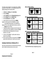
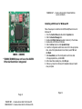
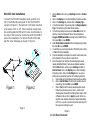
Installing LAN Drivers for Windows 98
Follow these steps to install the Intel 82559 LAN/Ethernet driver for
Windows 95:
1. From the Control Panel, double-click the System icon.
2. Click the Device Manager tab.
3. Double-click Other Devices or Network Adapters in the list area.
4. Double-click a PCI Ethernet Controller.
5. Click the Driver tab, then click Update Driver.
6. Click Next at the Update Device Driver Wizard.
7. Select "Display a list of all the drivers..." and click Next.
8. Insert the Intel adapter disk and click Have Disk.
9. Enter the appropriate drive for your disk media (A:) and click OK.
10. Click OK at the Select Device dialog box.
11. The Update Wizard displays the message that it has found the driver.
Click Next.
12. Click Finish.
13. Restart your computer when prompted.
Page 12
IBD69 / IBD693
IBD99 / IBD993
MicroPCI VGA/LAN Card
User’s Guide
LAN DRIVERS INSTALLATION
Making Floppy Disks for NetWare and Windows Installation
You need to use a floppy disk to install the LAN drivers. Use the MAKEDISK.BAT
utility located in the \LAN\I8255X\MAKEDISK directory on the CD.
MAKEDISK [operating system] [destination]
where [operating system] is the OS for which you are creating the
diskette, and [destination] is the drive letter and path (such
as A:). If no destination is specified, the A: drive will be used.
The possible [operating system] options are:
NT = Microsoft Windows NT
W2K = Microsoft Windows* 2000
W9X = Microsoft Windows* 95 and Windows 98
NW = Novell NetWare servers and clients
DOS = Microsoft DOS and IBM OS2
• IBD69/99 supports C&T 69000 (2MB
embedded)/IBD693/993 supports 69030 (4MB
embedded) VGA controller
• TFT LCD/DSTN LCD/CRT support
• Resolution / Colors / Refresh Rate
1280 x 1024 / 24bits (true color) / 60Hz
(supported by C&T 69030 only)
1280 x 1024 / 256 / 60Hz
1024 x 768 / 16bits (high color) / 85, 75, 60Hz
800 x 600 / 24bits (true color) / 85, 75, 60Hz
• Support drivers for Windows 95/98/NT4.0
Ethernet Features (IBD99/993)
•
•
•
•
Intel 82559 Single -chip Ethernet controller
10 BaseT/100 BaseTX support, full duplex
IEEE802.3, IEEE802.3U compliant
Backward Compatible with Intel 82558
Make sure you have a 1.44 MB formatted, non-bootable diskette in the floppy
drive when using this utility.
NOTE: The utility MUST be run from the\LAN\I8255X \MAKEDISK directory.
Alternately, you can use the following .BAT files (located
in the root directory on this CD) to simplify this process:
MAKEW9X.BAT -- Creates a drivers disk for Windows 95 and
Windows 98.
Page 3
Page 10
VGA Features
Installing the VGA Drivers for Windows 95/98
The following section describes the normal display driver installation
procedures for Windows 95/98. Use the following procedures when
installing the display drivers for Windows 95/98.
Click Start, then Settings, then Control Panel.
Double click Display.
Select the Settings tab, click the Change Display Type button.
Click the Change button under Adapter Type.
Click the Have Disk button and press OK.
Specify the path to the new driver and press <ENTER>:
Example 1: Insert the driver CD in the CD-ROM drive, and enter
d:\vga\ct69000\win95 (assuming D: is the CD-ROM drive.)
Example 2: If you're not sure exactly where the drivers are, click the
Browse button to find them.
7. The Select Device dialog box will appear. Select the hardware that
corresponds to the one you installed in your machine and click OK.
8. Windows 95/98 will copy the display drivers to the proper
directories on your system.
9. Continue by choosing Close. You will be asked to restart your
machine. Do so accordingly.
10. After the system has restarted, you can go back into the Display
applet and select alternate screen resolutions and color depths.
1.
2.
3.
4.
5.
6.
Installing the VGA Drivers for Windows NT 4.0
Once you are in the Windows NT 4.0 environment, follow the procedures
below to install the VGA drivers that come with your board.
JP2: LCD Power Setting
3.3V Setting
5V Setting
JP3: Onboard LAN Enable/Disable
JP3
Setting
Pin 1-2
Short/Closed
Enabled
Pin 2-3
Short/Closed
Disabled
JP4: Onboard C&T VGA Enable/Disable
JP4
Setting
VGA Function
Pin 1-2
Short/Closed
Enabled
Pin 2-3
Short/Closed
Disabled
* The SW1 DIP Switch is for manufacturing test only.
Page 5
Page 8
Jumpers and Connectors
LAN
MAKENW.BAT -- Creates a drivers disk for Novell NetWare
servers and clients.
Installing LAN Drivers for Windows 95
IBD99 / IBD993
* IBD69/IBD693 does not have the 82559
Ethernet Controller integrated
Page 2
MAKENT.BAT -- Creates a drivers disk for Windows NT.
MAKEW2K.BAT -- Creates a drivers disk for Windows 2000.
Follow these steps to install the Intel 82559 LAN/Ethernet driver for
Windows 95:
1. From the Control Panel, double-click the System icon.
2. Click the Device Manager tab.
3. Double-click Other Devices (question mark icon) in the list area.
4. Double-click a PCI Ethernet Controller.
5. Click the Driver tab, then click Update Driver.
6. Insert the Configuration and Drivers disk or CD in the appropriate
drive, and at the Update Device Driver Wizard, select "No" and
click Next.
7. Click Have Disk, insert the Configuration and Drivers disk
in the appropriate drive, and click OK.
8. At the Select Device dialog box, click OK again.
9. Follow any prompts for Windows 95 installation disks and restart
when prompted.
Page 11
MicroPCI Card Installation
1.
To insert the MicroPCI daughter cards, position it at
30° to the PCB and gently push it into the MicroPCI
connector (Figure 1). The card will not fit when inserted
at an angle of 45° or 15°. Once inserted, slowly press
the card towards the PCB until it locks on both sides to
the clips of the connector. Screw the card to the PCB to
secure the installation. To remove the MicroPCI card,
pull the ‘clips’ sideways as shown in Figure 2.
2.
3.
4.
5.
6.
7.
8.
9.
Figure 1.
Figure 2.
Page 4
Click the Start button, then go to Settings and click on Control
Panel.
Click on the Display icon to start the Display Properties window.
Click on the Settings tab, and then click on Display Type.
In the Change Display Type window, click on Change Adapter
Type. This will bring up the Select Device window.
In the Change Display window, click on Have Disk. Enter the
directory where the Windows NT driver files are located as
d:\vga\ct69000\winnt40 (assuming D: is the CD-ROM drive.)
Then select OK, or press ENTER.
Select Chips Video Accelerator from the display list provided,
then click OK or press ENTER.
You will then see a warning panel about Third Party Drivers. Click
on Yes to finish the installation.
Once the installation is complete, the system must be shut down
and restarted for the new drivers to take effect.
When the system has restarted, the default graphics mode
(usually 640x480x256color) has been automatically selected.
Click the Start button, and then go to Settings and click on
Control Panel. Click on the Display icon to start the Display
Properties window. Click on the Settings tab. A new screen
setting can be selected using either of the following methods:
A.
Use the slide-bar in the Desktop Area to select new setting.
B.
Click on List All Modes. From the list provided, select a
new setting, then click OK or press ENTER.
C.
Click on Test to test the newly selected graphics mode.
Follow the instructions given on screen. A test screen
should appear, followed by the Testing Mode window. Click
on Yes to continue. Click on Apply to switch to the new
graphics mode. Graphics modes are changed dynamically
on NT 4.0, so you do not need to shut down and restart for
the new screen settings to work.
Page 9
J1: LCD Panel Connector
Signal Name
GND
P34
P35
P30
P29
P25
P24
P23
P16
P17
P19
P13
P15
P7
5V or 3.3V
P9
P4
P3
P2
M
SHFCLK
FPVDD
FPVEE
GND
+12V
Pin #
1
3
5
7
9
11
13
15
17
19
21
23
25
27
29
31
33
35
37
39
41
43
45
47
49
Pin #
2
4
6
8
10
12
14
16
18
20
22
24
26
28
30
32
34
36
38
40
42
44
46
48
50
Signal Name
P33
P31
P32
P28
P27
P26
P21
P22
P20
P18
P14
P12
P11
P10
5V or 3.3V
P8
P6
P5
P1
P0
ENABKL
FLM(V SYNC)
LP(H S Y N C )
GND
+12V
JP1: WakeOnLAN Connector
1
2 3
Pin #
1
2
3
Signal Name
+5VSB
Ground
Wake on LAN
Page 6
Flat Panel Display Interface Pin Descriptions
Pin Name
P0
P1
P2
P3
P4
P5
P6
P7
P8
P9
P10
P11
P12
P13
P14
P15
P16
P17
P18
P19
P20
P21
P22
P23
P24
P25
P26
P27
P28
P29
P30
P31
P32
P33
P34
P35
SHFCLK
Pixels/Clk:
Mono Mono Mono Color Color Color Color Color
Color
Color
Color
Color
SS
DD
DD
TFT
TFT TFT TFT TFT+HR STN-SS STN-SS STN-DD STN-DD
8-bit 8-bit 16-bit 9/12/16 18/24 36-bit 18/24
8-bit
16-bit
8-bit
16-bit
24-bit
bit
bit
bit
(4bP)
(4bP)
(4bP)
(4bP)
D0
UD3 UD7
B0
B0
FB0 FB0
R1
R1
UR1
UR0
UR0
D1
UD2 UD6
B1
B1
FB1 FB1
B1
G1
UG1
UG0
UG0
D2
UD1 UD5
B2
B2
FB2 FB2
G2
B1
UB1
UB0
UB0
D3
UD0 UD4
B3
B3
FB3 FB3
B3
R2
UB2
UR1
LR0
D4
LD3 UD3
B4
B4
FB4 SB0
G4
G3
LR1
LR0
LG0
D5
LD2 UD2
G0
B5
FB5 SB1
R5
B2
LG1
LG0
LB0
D6
LD1 UD1
G1
B6 SB0 SB2
B5
R3
LB1
LB0
UR1
D7
LD0 UD0
G2
B7 SB1
B3
G3
LR2
LR1
UG1
LD7
G3
G0 SB2 FG0
B3
UG1
UB1
LD6
G4
G1 SB3 FG1
R4
UB1
LR1
LD5
G5
G2 SB4 FG2
G4
UR2
LG1
LD4
R0
G3 SB5 FG3
B4
UG2
LB1
LD3
R1
G4
FG0 SG0
R5
LG1
UR2
LD2
R2
G5
FG1 SG1
G5
LB1
UG2
LD1
R3
G6
FG2 SG2
B5
LR2
UB2
LD0
R4
G7
FG3 SG3
G6
LG2
LR2
R0
FG4 FR0
LG2
R1
FG5 FR1
LB2
R2 SG0
FR2
UR3
R3 SG1
FR3
UG3
R4 SG2 SR0
LR3
R5 SG3 SR1
LG3
R6 SG4 SR2
LB3
R7 SG5 SR3
FR0
FR1
FR2
FR3
FR4
FR5
SR0
SR1
SR2
SR3
SR4
SR5
SHFCL
K
SHFCL
K
SHFCL
K
SHFCLK
SHFCL
K
SHFCL
K
SHFCL
K
SHFCLK
SHFCLK
SHFCLK
SHFCLK
SHFCLK
8
8
16
1
1
2
2
2-2/3
5-1/3
2-2/3
5-1/3
8
Page 7