1
PTE P2B1-2/P5
Reference Manuals
Edition
Edition Date
Status
A Product of
:
:
:
1.0
28-03-2001
Proposed Issue
DOCUMENT IDENTIFICATION SHEET
DOCUMENT DESCRIPTION
Document Title
PTE P2B1 Reference Manual
EDITION :
Document Reference Number
1.0
EDITION DATE :
IE_PTE_P2B1_008
28-03-2001
Abstract
This document Contains a report on the Archtectural Design Phase of the development phase P2B1 of the PTE-P1/P2 tool to
fully support the FAT phase of the POEMS Ground Station. The document elaborates on the different sub modules required for
the development and details the design features of these sub modules.
Keywords
CONTACT PERSON :
A.Vander Cruyssen
TEL : +32 14 231811
:
DOCUMENT STATUS AND TYPE
STATUS
Working Draft
Draft
Proposed Issue
Released Issue
o
o
¤
CATEGORY
Executive Task
Specialist Task
Lower Layer Task
o
o
ELECTRONIC BACKUP
INTERNAL REFERENCE
NAME :
HOST SYSTEM
Mac OS 8.6 G3
Edition 1.028-03-2001 10:47
802 P2B1 Ref Manual v4.3.1.doc
MEDIA
Type : Hard disk
Media Identification :
SOFTWARE(S)
Word 98
PTE P2B1
Reference Manual
-3–
DOCUMENT APPROVAL
The following table identifies all authorities who have successively approved the present
issue of this document.
AUTHORITY
NAME AND SIGNATURE
DATE
Author
A. Vander Cruyssen
28-03-2001
Author
D. de Bal
28-03-2001
M. Vanuytven
28-03-2001
E. Moons
28-03-2001
Director ATC
Director Software
Department
Edition 1.028-03-2001 10:47
PTE P2B1
Reference Manual
-4–
TABLE OF CONTENTS
1.
Introduction ...................................................................................................................9
1.1
The PTE P2B1 Project ...........................................................................................9
1.2
Relation with PTE P2B2 Phase ..............................................................................9
1.3
Project Sections ................................................................................................... 10
1.3.1
PSR Scenario Generation: ............................................................................ 10
1.3.1.1 PSR Scenario Preparation/Generation :..................................................... 10
1.3.1.2 .S4 to Asterix/RDIF Compiler : ................................................................ 10
1.3.1.3 EDR Replay file streamer:........................................................................ 11
1.3.1.4 RDIF Protocol Viewer:............................................................................. 11
1.3.1.5 RDIF Convert:.......................................................................................... 11
1.3.2
Data Link Model B Capabilities ................................................................... 11
1.3.2.1 Data link Model B Surveillance Scenario: ................................................ 12
1.3.2.2 Data link Model B Event scenario ............................................................ 12
1.3.2.3 Data Link Analysis preparation : .............................................................. 12
1.3.3
Additional Capabilities................................................................................. 12
1.3.4
Sector Message Delay Analysis:................................................................... 12
1.3.5
Data Export.................................................................................................. 13
1.3.5.1 RFS Export: ............................................................................................. 13
1.3.5.2 I/VS Export: ............................................................................................. 13
1.3.5.3 I/RS Export : ............................................................................................ 13
1.3.5.4 A17 Export:.............................................................................................. 14
1.3.5.5 A18 Export:.............................................................................................. 14
1.3.5.6 A34 Export:.............................................................................................. 14
1.3.5.7 A48 Export:.............................................................................................. 14
2. Reference Documents.................................................................................................. 15
3. PTE - P2B1 Project Design......................................................................................... 17
3.1
Introduction ......................................................................................................... 17
3.1.1
Purpose ........................................................................................................ 17
3.1.2
Scope of PTE P2B1...................................................................................... 17
3.1.3
General Design Features.............................................................................. 20
3.2
PSR Scenario Generation ..................................................................................... 22
3.2.1
PSR scenario preparation/generation ............................................................ 22
3.2.1.1 Specifications........................................................................................... 22
3.2.1.2 Dataflow and User Interface ..................................................................... 26
3.2.1.3 Functional Description ............................................................................. 28
3.2.1.4 Generation Design Description................................................................. 29
3.2.1.4.1 1. Generation Rules ............................................................................ 29
3.2.1.4.2 False Target and Clutter Generation ................................................... 29
3.2.1.4.3 Generation of Genuine Radar Plots..................................................... 30
3.2.1.4.4 Generation of Sector Messages........................................................... 31
3.2.1.4.5 Combination of data ........................................................................... 31
3.2.2
S4 to ASTERIX/RDIF compiler................................................................... 32
3.2.2.1 Specifications........................................................................................... 32
3.2.2.2 Data Stream and User Interface ............................................................... 33
3.2.2.3 Functional description .............................................................................. 33
3.2.2.4 ASTERIX Cat001/Cat002 format ............................................................. 34
3.2.3
RDIF format................................................................................................. 34
3.2.3.1 Message transmission delay...................................................................... 35
Edition 1.028-03-2001 10:47
PTE P2B1
Reference Manual
-5–
3.2.4
EDR replay file streamer .............................................................................. 36
3.2.4.1 Specifications........................................................................................... 36
3.2.4.2 Data Stream and User Interface ................................................................ 37
3.2.4.3 Functional description .............................................................................. 37
3.2.4.4 Firmware.................................................................................................. 38
3.2.4.5 Software................................................................................................... 39
3.3
Data-Link Model B Capabilities........................................................................... 42
3.3.1
Data link model B Surveillance Scenario...................................................... 42
3.3.1.1 Specification ............................................................................................ 42
3.3.1.2 Data Stream and User Interface ................................................................ 44
3.3.1.3 Functional Description ............................................................................. 45
3.3.1.4 Detailed Description................................................................................. 47
3.3.1.4.1 Background scenario generation ......................................................... 47
3.3.1.4.2 Sector generation................................................................................ 48
3.3.2
DatalinkModel B Event Scenario Generation ............................................... 49
3.3.2.1 Specification ............................................................................................ 49
3.3.2.2 Data Stream and User Interface ................................................................ 51
3.3.2.3 Functional Description ............................................................................. 53
3.3.2.3.1 Manual Method of event generation ................................................... 53
3.3.2.3.2 Automatic Method of event generation .............................................. 55
3.3.3
Data-link model B Replay ............................................................................ 57
3.3.3.1 Specification ............................................................................................ 57
3.3.3.2 System overview ...................................................................................... 57
3.3.4
Data link Analysis ........................................................................................ 57
3.3.4.1 Specification ............................................................................................ 57
3.3.4.2 Functional Description ............................................................................. 59
3.4
Additional Capabilities ........................................................................................ 62
3.4.1.1 Specification ............................................................................................ 62
3.4.1.2 User Interface........................................................................................... 62
3.4.1.3 Functional Description ............................................................................. 63
3.4.1.4 Transponder Level Checks ....................................................................... 64
3.4.1.5 BDS 10 contents Verification ................................................................... 66
3.4.1.6 Use of colours for specific transponders. .................................................. 67
3.5
Sector message delay analysis.............................................................................. 70
3.5.1
Specifications............................................................................................... 70
3.5.2
User Interface............................................................................................... 70
3.5.3
Functional description .................................................................................. 71
3.5.4
Sector message delay recording.................................................................... 72
3.5.5
Sector message delay analysis ...................................................................... 73
3.6
Data Export.......................................................................................................... 76
3.6.1
RFS Export .................................................................................................. 76
3.6.1.1 Specifications........................................................................................... 76
3.6.1.2 User Interface........................................................................................... 77
3.6.1.3 Functional description .............................................................................. 78
3.6.1.4 RFS data format ....................................................................................... 79
3.6.2
Export of I/RS Data...................................................................................... 81
3.6.2.1 Specifications........................................................................................... 81
3.6.2.2 Functional description .............................................................................. 83
3.6.2.3 Interrogation-Reply DSS file ................................................................... 85
Edition 1.028-03-2001 10:47
PTE P2B1
Reference Manual
-6–
3.6.2.4 Interrogation/Reply Viewer tool .............................................................. 87
3.6.3
Export of I/VS Data ..................................................................................... 88
3.6.3.1 Specifications........................................................................................... 88
3.6.3.2 Functional description .............................................................................. 88
3.6.3.3 RVI redesign ............................................................................................ 88
3.6.3.3.1 Video Problems.................................................................................. 89
3.6.3.3.2 Inclusion of OBI recording in firmware and Software......................... 89
3.6.3.3.3 Retrigger Feature................................................................................ 89
3.6.3.3.4 Range Limitation................................................................................ 90
3.6.3.3.5 Digital Pulse Compression Limitation ................................................ 90
1.1.1.1.1. Miscellaneous design improvements.................................................. 90
3.6.3.4 IRD file generation................................................................................... 90
3.6.3.5 IVS export................................................................................................ 90
3.6.4
Export of ASTERIXCat 17,18,34 and 48 data .............................................. 92
3.6.4.1 Specifications........................................................................................... 92
3.6.4.2 File Format A17 Data............................................................................... 93
3.6.4.3 File Format A18 Data............................................................................... 94
3.6.4.4 File Format A34 Data............................................................................... 96
3.6.4.5 File Format A48 Data............................................................................... 97
3.6.4.6 Functional description .............................................................................. 99
3.6.4.7 File Format S18 Data ............................................................................... 99
3.6.4.8 File Format S48 Data ............................................................................. 100
Edition 1.028-03-2001 10:47
PTE P2B1
Reference Manual
-7–
TABLE OF FIGURES
Figure 3-1: POEMS Context ....................................................................................................................................17
Figure 3-2: PTE Generation overview....................................................................................................................18
Figure 3-3: POEMS Recording Data.......................................................................................................................19
Figure 3-4: PSR Scenario replay functions ............................................................................................................22
Figure 3-5: Preferences input for PSR Scenario preparation .............................................................................27
Figure 3-6: PSR Replay Preferences........................................................................................................................28
Figure 3-7: PSR Compilation Monitoring..............................................................................................................33
Figure 3-8: EDR Replay functionality ....................................................................................................................34
Figure 3-9 EDR Replay file streamer user interface ...........................................................................................37
Figure 3-10: EDR Replay Functional overview ....................................................................................................38
Figure 3-11: UTC Synchronisation for EDR Replay ............................................................................................39
Figure 3-12 Trajectory Scenario Generator Randomiser Input .........................................................................45
Figure 3-13 Example of generated Surveillance part of Datalink Scenario ....................................................46
Figure 3-14: Sector distribution...............................................................................................................................47
Figure 3-15: Event scenario Generator panel........................................................................................................52
Figure 3-16: Input of Data-Link event parameters ..............................................................................................53
Figure 3-17: Overview of datalink Event editing for Manual Datalink Model Generation ........................55
Figure 3-18: Transponder database changes for PTE P2B1.......................................................................................63
Figure 3-19: BDS 10 verification..............................................................................................................................67
Figure 3-20: Setup for EDR Recording For sector delay analysis .....................................................................72
Figure 3-21: Sector message Analysis ....................................................................................................................73
Figure 3-22: RFS Data Export functionality ..........................................................................................................78
Figure 3-23: IRS Export from Scenario Time merger ..........................................................................................84
Figure 3-24: Mode S reply at close range on bad monitor outputs ..................................................................89
Figure 3-25: Export of IVS data ...............................................................................................................................91
Figure 3-26: ASTERIX export tool overview.........................................................................................................99
Edition 1.028-03-2001 10:47
PTE P2B1
Reference Manual
-8–
EXECUTIVE SUMMARY
As part of the Mode S development program, standard analysis tools are required to evaluate
the performance of the Pre-Operational European Mode S (POEMS) stations being
developed. It is intended that the POEMS Test Environment (PTE) will fulfil this objective
by combining the capabilities of various test tools - the PTE -P1, P2A, P2B1, P2B2, P3, P4
and P5.
Intersoft Electronics was honored with the development of phases P1, P2A, P2B1 and P2B2 .
As a result, this document represents the Intersoft Ideas on the development of PTE P2B1.
This Section of the development deals with new functions for the target simulator, data
recording, data exporting and Factory Acceptance Test tool (PTE-P1/P2B1
Part of the requirements of this tool will be covered by the adaptation or upgrading of
existing PTE P1 software, whereas some subsections will require new development of tools.
Edition 1.028-03-2001 10:47
PTE P2B1
Reference Manual
-9–
1. Introduction
This document describes the Design of the P2B1 development phase of the PTE (
POEMS Test Environment) project.
The l Design is based on the specifications as laid down in the “System Requirement
Document PTE P2B1” created by Intersoft prior to creating the ADD.
Furthermore, PTE P2B1 is intended to be a preparation stage for the PTE P2B2 stage,
in which enhanced Datalink analysis will be implemented. Since Intersoft was also
honoured with the development of this further stage, some sections of this ADD will
already deal with design items intended for the PTE P2B2 stage.
1.1
The PTE P2B1 Project
As a logical enhancement of the PTE P1 tool, the PTE P2B1 project will add a
number of additional functions to the PTE set of tools.
P2B1 will especially deal with some additional data generation and the exporting
and preparation of capture P1 data.
The PTE-P2 (Phase P2B1) additional capabilities are the following :
§ PSR Scenario Generation: to Define the Characteristics of the PSR Information
that will be provided through the Real Time PSR Data Simulation.
§ data link Model B Capabilities
§ Additional Scenario Capabilities
§ Sector Message Delay Analysis
§ Data Export
Several of these functions will be embedded in existing PTE P1 functions or tools,
since this will be the most logical way of design. These changes will be visible to the
user under the form of new buttons, new user interface windows or simply an
improved functionality. Additionally, some completely new tools will emerge in the
PTE toolbox.
The Primary scenario generation will form an implicit part of the existing P1
Trajectory scenario generator. This generator will be enhanced with a simulated PSR
scenario data output. The parameters defining this scenario ( rotation speed, location
of PSR radar, jitter, clutter, etc.. ) can be entered from within the trajectory scenario
generator’s user interface.
A second part of the tool will read the generated PSR scenarios and play the data in
real time using the P1 EDR hardware platform. This will supply the POEMS radar
with Asterix Cat 1 and 2 data under LapB protocol.
A second enhancement of the trajectory scenario generator is the automatic
generation of “data link” scenarios. These scenarios are predefined by Eurocontrol
and will allow extensive testing of the data link features of any POEMS radar. The
P2B2 phase of the project will deal with the analysis of the recorded data.
1.2
Relation with PTE P2B2 Phase
For the P2B2 analysis, the P2B1 tool must combine a number of existing data files and
generate sufficient data for the automatic analysis in PTE P2B2.
Edition 1.028-03-2001 10:47
PTE P2B1
Reference Manual
- 10 –
PTE-P2B2 (Phase P2B2) is a specific tool for the assessment of the data-link
performance of the POEMS station.
The PTE-P2 (Phase P2B2) capabilities are the following :
•
Importing of Data from PTE-P1/P2B1.
•
Linking, Filtering and Managing the Imported Data.
•
Data Link Performance Analysis.
•
Display and Output of Analysis Results.
P2B1 will prepare all recorded data such that it can be analysed in the next
development phase.
1.3
Project Sections
1.3.1
PSR Scenario Generation:
A first major development task in P2B1 is the generation of Primary data. For this
purpose, the design will be split in four modules
§ PSR Scenario Preparation/Generation: Embedded in P1 Trajectory scenario
generator
§ .S4 to Asterix and RDIF Compiler : Embedded in P1 Trajectory scenario
compiler.
§ EDR replay File streamer: New user interface
Additionally, two test modules will be added, namely an RDIF protocol viewer and
an RDIF convert tool, allowing for better debugging and verification of the generated
RDIF.
1.3.1.1
PSR Scenario Preparation/Generation :
This module produces .a S4PR data file with PSR positional information, to be
converted into RDIF or Asterix
The tool is Embedded in P1 Trajectory scenario generator
As an input, the scenario generator will use the parameters specified by the user in
the trajectory scenario generator ( P1 development). These parameters are defined in
the SRD.
As an output, the Scenario generator shall create an S4 data file ( positional
information) which contains one record per generated PSR plot. The datafields will
include position, power, etc.. of each PSR plot.
1.3.1.2
.S4 to Asterix/RDIF Compiler :
This module converts the generated S4 file into Asterix Cat 001 and 002 or RDIF .
The tool is embedded in the P1 Trajectory scenario compiler..
As input, the module requires a .S4 data file. This can be generated by the trajectory
scenario generator.
Edition 1.028-03-2001 10:47
PTE P2B1
Reference Manual
- 11 –
As an output, the module produces an EDR replay file , to be replayed by the EDR
replay module.
Optionally, SSR and Mode S data can be converted into asterix Cat 048 data for test
purpose. This function will be implemented into a new user interface test tool. ( Not
part of P2B deliverable.
1.3.1.3
EDR Replay file streamer:
From the generated Asterix and RDIF EDR Replay files , the EDR replay tool will
generate live RDIF or Asterix using the EDR active playback line.
The tool will use a new user interface
As input, the module requires an EDR replay file. This can be generated by RDIF or
Asterix generator modules
As an output, the module produces RDIF or Asterix under LapB dataflow on the PTE
P1 specified hardware connections ( EDR channel)
1.3.1.4
RDIF Protocol Viewer:
For debug and test features, it is required to verify the generated RDIF data. The
protocol viewer can be tested on its own using a known data set ( e.g. DERA RDIF
data) , after which the PTE P2B1 generated RDIF can be verified using the protocol
viewer.
The tool will be embedded into the existing P1 Protocol viewer.
As an input, this module requires an RDIF recording as recorded by the P1 EDR
hardware platform.
As an output the tool produces text data and files explaining the contents of the
RDIF and other protocols.
1.3.1.5
RDIF Convert:
After RDIF generation, it is a good practise to verify the generated RDIF with the
initial S4 data set. This can be done by entering the RDIF format in the EDR Convert
program. This will allow S4 data to be generated from recorded LapB RDIF data.
This tool is embedded into the existing P1 EDR Serial Convert tool.
As an input, this module requires an RDIF recording as recorded by the P1 EDR
hardware platform.
As an output the tool produces an S4 positional datafile converted from the contents
of the RDIF protocol.
1.3.2
Data Link Model B Capabilities
A second important part of the project is the automatic generation of a datalink
scenario. This will be implemented using the existing PTE P1 scenario generator and
event scenario generator. Both tools will include new functions for the generation of
these scenarios.
Edition 1.028-03-2001 10:47
PTE P2B1
Reference Manual
1.3.2.1
- 12 –
Data link Model B Surveillance Scenario:
The trajectory scenario generator must be enhanced with a Randomiser function
which can generate a data link positional scenario as described in the SRD.
This tool is an enhancement of the existing P1 trajectory scenario generator tool.
As an input the module uses a user interface panel specifying the Random positional
parameters for the datalink model.
As an output, the module produces a scenario specification list, which can be
compiled, edited or saved using the trajectory scenario generator.
1.3.2.2
Data link Model B Event scenario
The Event scenario generator must be enhanced with a Randomiser function which
can generate a data link event scenario as described in the in the SRD .
This tool is an enhancement of the existing P1 event scenario generator tool.
As an input the module uses a user interface panel specifying the Random event
parameters for the datalink model.
As an output, the module produces an event scenario specification list, which can be
compiled, edited or saved using the event scenario generator.
1.3.2.3
Data Link Analysis preparation :
The Generated .S4EV data file from the event scenario generator shall contain some
fields entered for future data link analysis ( PTE P2B2). SRD .
This tool is an enhancement of the existing P1 event scenario generator tool.
As an input the module uses a user interface panel specifying the Random event
parameters for the datalink model.
As an output, the module produces an S4EV file, which can later be analysed using
PTE P2B2 functions.
1.3.3
Additional Capabilities
Some specific requirements have been included in PTE P2B1, which call for specific
research work to include the correct protocols for the simulation of Annex 10
amendment 69 or 71 compatible transponders.
This tool is an enhancement of the existing P1 event scenario generator tool.
Some minor changes are required to the trajectory scenario generator to allow
generation of amendment 69 or 71 transponders. Also the handling of CA fields shall
be improved with better user interface.
1.3.4
Sector Message Delay Analysis:
The sector delay analysis deals with the analysis of the delay between timestamps of
Sector messages and internal time stamping of these sector messages. This requires
an adaptation of the Asterix EDR convert tool so that it can generate “Sector”
Edition 1.028-03-2001 10:47
PTE P2B1
Reference Manual
- 13 –
message- formatted S4 records and includes time and azimuth of recording in the
required fields for such a record. The real analysis of the delays can be performed
using the inventory tool.
This tool is an enhancement of the existing EDR serial Convert tool and the existing
Inventory tool.
As an input the module uses an EDR recording containing Cat 34 radar data.
As an output, the module produces line graphs representing sector delay versus
time, scan number or azimuth, and/or histogram graphs.
1.3.5
Data Export
An important part of P2B1 is the data export feature. This requires the conversion of
generated PTE P1 data into user specified data formats ( excel formats) which can be
used for later analysis.
These export functions also include the creation of sufficient data for the PTE P2B2
project analysis features.
1.3.5.1
RFS Export:
The generated S4 data file can be exported into an Excel format after generation and
time stamping. This is done by using the “Scenario Time Merger” tool and exporting
it using the Inventory tool. This export needs an update to incorporate all data fields
present in the S4 data.
This tool is an enhancement of the existing Inventory tool.
The tool will import any .S4 data files
The tool will generate a tab spaced excel compatible data file containing all S4 fields
as an output.
1.3.5.2
I/VS Export:
The RVI-RVR recorded data must then be exported in a specific format described in
Ref. 29. This export function shall be incorporated in the “Reference Extractor”
function of the PTE tool.
This tool is an adaptation of the existing P1 “Analysise Pulse Recordings.vi” tool and
requires a new user interface tool, “Reply-Interrogation Viewer”.
The module will use RVI and RVR recorded “ Pulse recording” ( PTE P1
functionality) .
The module will produce the I/VS data from the required input.
1.3.5.3
I/RS Export :
A special tool needs to be created which creates the I/RS ( Interrogation and Reply
data , as generated from the RES result recordings ) from the current recorded RES
data files.
This tool is an adaptation of the existing P1 “Scenario Time Merger” tool
Edition 1.028-03-2001 10:47
PTE P2B1
Reference Manual
- 14 –
The tool will import RES recorded Interrogation/reply file and a scenario file .
The tool will generate a tab spaced excel compatible data file containing all
Interrogation and Reply data fields as an output.
1.3.5.4
A17 Export:
A special convert tool will be generated which creates a text file ( format described in
Ref. 29) containing all Asterix Cat 17 fields and sub-fields.
This tool a new user interface tool, “Asterix Export”.
As an input, this module requires an EDR Asterix Cat 17 recording as recorded by
the P1 EDR hardware platform.
As an output the tool generates a tab spaced excel compatible data file containing all
Asterix Cat 17 data fields as an output.
1.3.5.5
A18 Export:
A special convert tool will be generated which creates a text containing all Asterix
Cat 18 fields and subfields.
This tool a new user interface tool, “Asterix Export”.
As an input, this module requires an EDR Asterix Cat 18 recording as recorded by
the P1 EDR hardware platform.
As an output the tool generates a tab spaced excel compatible data file containing all
Asterix Cat 18 data fields as an output.
1.3.5.6
A34 Export:
A special convert tool will be generated which creates a text containing all Asterix
Cat 34 fields and subfields.
This tool a new user interface tool, “Asterix Export”.
As an input, this module requires an EDR Asterix Cat 34 recording as recorded by
the P1 EDR hardware platform.
As an output the tool generates a tab spaced excel compatible data file containing all
Asterix Cat 34 data fields as an output.
1.3.5.7
A48 Export:
A special convert tool will be generated which creates a text file ( format described in
Ref. 29) containing all Asterix Cat 48 fields and subfields.
This tool a new user interface tool, “Asterix Export”.
As an input, this module requires an EDR Asterix Cat 48 recording as recorded by
the P1 EDR hardware platform.
As an output the tool generates a tab spaced excel compatible data file containing all
Asterix Cat 48 data fields as an output.
Edition 1.028-03-2001 10:47
PTE P2B1
Reference Manual
- 15 –
2. Reference Documents
Ref. 1. Radar Surveillance in En-Route Airspace And Major Terminal Areas. 006-95
EUROCONTROL. 19 May 1995.
Ref. 2.
Ref.
EATCHIP. POEMS User requirements for tools. Edition 1.1. SUR.ET2.ST03.3110-xx-xx.
Draft. 6 May 1996.
3 .EATCHIP. Pre-Operational European Mode-S Functional
EUROCONTROL SUR-ET2-ST03.3110-SPC-01-00. Edition 2.0.
Specification.
Ref. 4.
STANAG 4193 NATO Technical characteristics of IFF MK XA and MKXII Interrogators
and Transponder’.
Ref. 5.
ICAO Annex 10, Aeronautical Communications. Volume IV, First Edition July 1995 and
including up to Amendment 71.
Ref. 6.
Radar Sensor Performance Analysis. EUROCONTROL, SUR.ET01.ST03.1000-STD-01,
Edition 0.1, June 1997 Working Draft.
Ref. 7.
ICAO Annex 10, Aeronautical Communications. Volume III, First Edition July 1995 and
including up to Amendment 71.
Ref. 8.
Manual on Mode S Specific Services ICAO document 9688-AN/952 First edition, 1997
(including amendment I).
Ref. 9.
"Manual on testing of radio navigation aids" Vol. III (Testing of Radar Surveillance
System) ICAO document 8071.
Ref. 10. RCEL Document (Ref. IC 808371/705 Dated September 97 Issue 0.C) Interface Control
Document for the interface between the Interrogator and the PTE equipment.
Ref. 11. RCEL Document (Ref. IC 808371/000 Dated October 1997 Issue A) Interface Control
Document for POEMS Ground Station
Ref. 12. Airsys Document (Ref. CDRL SE-ICD-001 Dated April 1997 Issue V01.00) Interface
Control Document.
Ref. 13. Airsys Document (Ref. CDRL SE-ICD-209 Dated 20 March 1998 Issue V01.00) Interface
Control Document.
Ref. 14.
Manual of the Secondary Surveillance Radar (SSR) Systems ICAO Document 9684 First
Edition-1997.
Ref. 15. Eurocontrol Standard Document for Radar Data Exchange Part 2a Transmission of
Monoradar Data Target Reports Ref. SUR.ET1.ST05.2000-STD-02a-01 Ed 1.0 November
1997 Released Issue.
Ref. 16. Eurocontrol Standard Document for Radar Data Exchange Part 2b Transmission of
Monoradar Service Messages Ref. SUR.ET1.ST05.2000-STD-02b-01 Ed 1.0 November
1997 Released Issue.
Ref. 17.
POEMS Document for ASTERIX Category 017 Transmission of Mode S Surveillance Coordination Function Messages Ref. SUR.ET2.ST03.3111-SPC-02-00 Ed 0.5 February 1999
Proposed Issue.
Ref. 18.
POEMS Document for ASTERIX Category 018 (Part 6) Transmission of Mode S Datalink
Function Messages Ref. SUR.ET2.ST03.3112-SPC-02-00 Ed 1.5 March 1999 Proposed
Issue.
Edition 1.028-03-2001 10:47
PTE P2B1
Ref. 19.
Reference Manual
- 16 –
POEMS Document for Radar Data Exchange Part 2b Transmission of Monoradar Service
Messages Ref. SUR.ET2.ST03.3116-SPC-02b-01 Ed 1.3 16 March 1999 Proposed Issue.
Ref. 20. POEMS Document for Radar Data Exchange Part 4 Transmission of Monoradar Target
Reports Ref. SUR.ET2.ST03.3115-SPC-04-01 Ed 1.3 12 March 1999 Proposed Issue.
Ref. 21. Radar Data Interchange Format (RDIF) CAA Paper 87002 Second Edition November
1991.
Ref. 22. PTE-P1/P2 Interface Control Document Version 2.3 Intersoft Electronics dated
22/2/2000.
Ref. 23.
User application profile for plot messages + Encoding rules for Data Items Category 1,
Ref. DFS HV SNO3 DZ, Version 1, 21.04.93.
Ref. 24. User application profile for extractor monitoring messages (Version 1, 05.08.92) +
Encoding rules for Data Items Category 2 (Version 2, 21.04.93), Ref. DFS HV SNO3 DZ.
Ref. 25. Requirement specification of the P2B development phase of the POEMS Test
Environment PTE-P1/P2 Ref. SUR.ET2.ST06.2202-SPE-02-01 Ed. 3.0 Dated 04 June 1999
Released Issue
Ref. 26.
User Manual RASS-S4 v 4.1 December 1999 Intersoft Electronics 21/12/1999
Ref. 27. Requirement specification of the PTE P2B1 Development Phase of the POEMS Test
Environment PTE-P2B; Edition 1.1 12/10/1999
Ref. 28.
PTE P2B1 Project Plan Edition 1.0 31/1/2000
Ref. 29.
PTE P2B1 System Requirement Document Second edition v 1.2 20/7/2000
Ref. 30.
PTE P2B1 Architectural Design Document Second edition v 1.2 20/7/2000
Ref. 31. PTE-P1 Architectural
14/04/1999.
Edition 1.028-03-2001 10:47
Design Document Version 4.1 Intersoft Electronics dated
PTE P2B1
Reference Manual
- 17 –
3. PTE - P2B1 Project Design
3.1
Introduction
In the first phase (P1) of the PTE (POEMS Test Environment) development the
emphasis was put on the simulation of the environment, the recording and analysis
of signals at different levels in the radar chain.
In the second stage ( P2B), additional simulation capabilities will be added and
further development effort will be put in the analysis of all recorded data.
3.1.1
Purpose
The purpose of the PTE P1/P2 is to create a test environment by mimicking the
behaviour of multiple aircraft at antenna level for MSSR/SSR and at plot level for
PSR to simulate the future environment in which a POEMS station is to be used.
Furthermore, PTE P1/2 has the task of recording all required analysis data and
formating it into the right format for further analysis. Some of this analysis can be
done on the PTE P1/P2 platform itself, other must be performed on the P4 platform
or using external analysis tools ( e.g. Excel spreadsheet program).
By recording the interrogations and output of the station for such a repeatable
“virtual“ environment, the performance of the radar can be analysed.
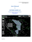
Three important parts can be distinguished :
§ 1. The generation of test signals to simulate a specific environment
§ 2. The recording of all important signals
§ 3. The Analysis of all Recorded data
1. Environment
Simulation
POEMS Station
under test
2. Recording
3. Analysis
Figure 3-1: POEMS Context
3.1.2
Scope of PTE P2B1
The scope for the P2B1 project must be seen within the general PTE P1/P2 project.
At the end of the P2 development, the PTE P1/2 shall provide the user with the
possibility of generation of a arbitrary scenario and compile this scenario into
sufficient data files to feed two types of hardware devices:
§ The RES ( or Radar Environment Simulator)
§ The EDR ( Extended Data Recorder / Replayer)
These devices will then provide in turn the required input to the POEMS radar for it
to operate under simulated conditions which are as close as possible to a future (
highly loaded) real environment. For this purpose, PTE will create scenario
information and provide the radar with SSR or Mode S replies, simulate Mode S
protocols ( among which all data link protocols) , simulate possible outputs of a colocated or nearby PSR radar (P2B1) and generate cluster information (P3).
Edition 1.028-03-2001 10:47
PTE P2B1
Reference Manual
Scenario
InfoTransponder
infoRadar
infoAircraft
infoEnvironment
infoRotational
infoPSR Info
- 18 –
Trajectory
Scenario
Generator
Event
Scenario
Generator
PSR
Driver
*
Ch1
RESDriver
GDLP
Driver
*
EDR
Events
infoData link
infoGDLP
events
ESG
Extended Scenario
Ch2
Harddisk
Cat001/002
Cat018
RIU
IF/Timing
Radar Interface
and Up convertor
LAPB
RF/Timing
Radar
*Functionalities can not be
run simultaneously!
Figure 3-2: PTE Generation overview
Once the scenario is running, PTE P1 Records data at different levels:
§ Air level: : Interrogations send by Radar captured by RFA
§ Interrogations and Replies: I/RS data : Recorded by RES at generation
§ Video Level: Interrogations and Replies and Video Data recorded by RVR/RVI
§ Digitised level: No recording performed
§ Service level: Syncro time, Pimary input,
§ Network level: Asterix Cat 34,48,17 and 18
PTE P2B1 will use this data and convert it into the necessary formats such that
analysis is possible.
Some important sections of the analysis are already available in PTE P1:
§ Pd calculation
§ Accuracy Calculation
§ Data Visualisation in numerous combinations.
§ Interrogation schedule analysis
Edition 1.028-03-2001 10:47
PTE P2B1
Reference Manual
- 19 –
POEMS
Station under test
1 Air Level Interrogations (Uplink HPD)
2. Interrogations/Replies (I/RS)
3 Rotational Information ACP / ARP
4. Video Level Replies/Interrogations
5. Surveillance Data Asterix Cat34/48
6. Data Link Asterix Cat 18
7. Cluster Information Asterix Cat17
8. Primary Data Asterix Cat1,2 / RDIF
9. Syncro Time
Simulation
Antenna system
Recording
Analysis
RFA
1
Antenna
RF level
Interrogations/
Replies
RES
RES
2
ACP/
ARP
3
Video
level
ACP
ARP
Interrogation
Interrogator
Receiver
Transmitter
4
RVI
Video Signal
Processor
Video
Sector Delay
RVR
Plot &Track
9
Radar Processing
Digitised
level
System
Management
Function
Service
level
EDR
8
Surveillance
Coordination
Function
Datalink
Function
Datalink
EDR
Converts
P1-P4
I/RS
I/VS
RFS
A17
A18
A34
A34
Network
level
6
5
7
Figure 3-3: POEMS Recording Data
Additional analysis need to be developed in PTE P2B:
§ Sector message delay analysis (P2B1)
§ Datalink analysis (P2B2)
Edition 1.028-03-2001 10:47
PTE P2B1
Reference Manual
3.1.3
- 20 –
General Design Features
The PTE P2B1 project is mostly a Software project. No real Hardware modules are to
be designed, except for a small redesign of the RVI, which is required for the correct
recording of the I/VR data.
For the creation of the software, we will make use of LabVIEW, which is the
programming language of the other PTE P1 and P2A tools. LabVIEW provides the
user of the final product with a number of build in features, such as on line
documentation using a floating window.
The user interface of PTE P2B1 will be no different from the PTE P1 design, since the
same basic building functions and user interface design will be used.
Edition 1.028-03-2001 10:47
PTE P2B1
Reference Manual
PSR Scenario Generation
Edition 1.028-03-2001 10:47
- 21 –
PTE P2B1
Reference Manual
3.2
- 22 –
PSR Scenario Generation
A large part of the PSR scenario generation already exist in the form of the PTE P1
scenario generator. As an input to the P1 scenario generator, the user can define a
arbitrary surveillance scenario in the form of “sentences” plus a set of start
conditions. On top of this, the user needs to define additional radar information such
as rotation speed, reflection definitions, etc.. All input parameters are defined in the
SRD (Ref. 29. The trajectory scenario generator will output ( after the embedded
compilation stage) sufficient data for the EDR Reply function to generate Asterix or
RDIF type messages for PSR data simulation. ( Remark: Figure 3-4 shows the S4 to
Asterix/RDIF compiler as a separate tool, but in reality it is embedded in the
existing Trajectory scenario compiler)
PSR Scenario
generator
S4PR file
Trajectory Scenario Generator
Inventory
S4 to
ASTERIX/RDIF
compiler
EDR replay file
Streamer
EDR replay file
EDR Serial Recording
EDR replay function
Figure 3-4: PSR Scenario replay functions
3.2.1
PSR scenario preparation/generation
3.2.1.1
Specifications
Following Specifications are of importance for this module of the PTE P2B1
development. Details can be found in the SRD ( Ref. 29).
[P2B1-SR-CAP-0100] An additional compiler module shall be created as a sub
module of the Trajectory scenario generator. This compiler shall generate a new S4
positional file ( . S4PR) , which includes all the specified targets. ( including clutter
etc... ) . This implies that the scenario selected in the trajectory scenario generator will
be used to generate the asterix or RDIF data. All scenario definition, loading, saving
and modifications shall be performed from the trajectory scenario generator. All
random parameters definitions of the scenario shall be embedded in the scenario
Edition 1.028-03-2001 10:47
PTE P2B1
Reference Manual
- 23 –
after compilation. If a new random seed is required, the scenario shall need to be
recompiled.
[P2B1-SR-CAP-0101] The PTE-P2B1 tool shall enable the user to specify a target
scenario on which the generation of PSR target report and radar service messages for
input to the POEMS SUT is to be based and to which it will be associated. This
selection shall be performed from within the trajectory scenario generator .vi , which
is an existing tool in P1.
[P2B1-SR-CAP-0102] The PTE-P2B1 tool shall enable the user to specify the following
parameters to be used during the PSR scenario replay run for the simulated PSR
radar . The parameters shall be selectable from within the trajectory scenario
generator.
§ user selection of either (a) simulated PSR co-mounted and synchronised with
the POEMS SUT or (b) simulated PSR co-located and not synchronised with an
azimuth start offset (in the interval 0 to 360 degrees with a granularity of 1
degrees) from the POEMS SUT
§ for selection (b) only, the simulated PSR position as the combination of a range
offset (in the interval 0 to 5 nm with a granularity of 0.01 nm) and an azimuth
offset (in the interval 0 to 360 degrees with a granularity of 0.01 degrees) from
the POEMS SUT.
§ for selection (b) only, the simulated PSR rotation speed (in the interval 4.5 to 15
rpm with a granularity of 0.1 rpm).
§ simulated PSR probability of detection (in the interval 85 to 100% with a
granularity of 0.1%)
§ simulated PSR maximum detection slant range (in the interval 0 to 256 nm with
a granularity of 1 nm)
§ simulated PSR background false target report message generation rate (in the
interval 0 to 100 false target reports per radar per scan with a granularity of 1
false target report per radar per scan)
§ simulated PSR clutter area parameters - minimum range, maximum range,
minimum azimuth, maximum azimuth and rate of false PSR target report
generation (in the interval 0 to 100 per radar scan with a granularity of 1 per
radar scan)
§ simulated PSR azimuth bias parameter (in the interval 0 to 0.2 degrees with a
granularity of 0.01 degrees)
§ simulated PSR range gain and offset bias parameters (gain in the interval 0 to 2
metres/nm with a granularity of 0.1 metres/nm, offset in the interval 0 to 150
metres with a granularity of 1metres)
§ simulated PSR time stamp bias parameter (in the interval 0 to 200 ms with a
granularity of 1 ms)
§ simulated PSR azimuth stochastic error standard deviation (interval 0 to 0.2
degrees with a granularity of 0.01 degrees)
§ simulated PSR range stochastic error standard deviation (interval 0 to 150
metres with a granularity of 1 metres)
[P2B1-SR-CAP-0103] Within the PTE-P2B1 tool, the user shall be able to define, load,
modify, save (to be retrieved in a later session) and delete these PSR scenario
parameters under one PSR scenario file name associated to the corresponding
POEMS target scenario.
[P2B1-SR-CAP-0104] The PSR scenario generation functionality of the PTE-P2B1 tool
shall enable the user to specify re-use of the same random number generator seed
values used in a previous simulation run or the use of new seed values. The intention
Edition 1.028-03-2001 10:47
PTE P2B1
Reference Manual
- 24 –
of this requirement is to enable the user to exactly duplicate or not the results of a
previously run scenario. This shall be achieved via replay of identically the same
scenario file or by recompiling the scenario.
[P2B1-SR-CAP-0105] The PSR scenario generation of the PTE-P2B1 tool shall be
capable of generating PSR target reports and service messages from a simulated
radar which is co-mounted and synchronised with the POEMS SUT when specified
in the PSR scenario.
[P2B1-SR-CAP-0106] The PSR scenario generation of the PTE-P2B1 tool shall be
capable of generating PSR target reports and radar service messages from a
simulated radar which is co-located and not synchronised with the POEMS SUT .
In this case the PSR target report messages shall take into account the user specified
PSR position using a flat earth model.
[P2B1-SR-CAP-0107] For the co-located simulation case the PTE-P2B1 tool shall
generate the PSR target report and service messages from a PSR radar head that is
offset in position from the POEMS SUT by the PSR scenario specified values.
[P2B1-SR-CAP-0108] For the co-located simulation case the PTE-P2B1 tool shall
generate the PSR target report and radar service messages from a PSR radar head
with PSR scenario specified rotation speed.
[P2B1-SR-CAP-0109] The algorithm used by the PTE-P2B1 tool in order to calculate
the time and position of the simulated PSR target shall be that currently used in the
PTE-P2B1 scenario generator for the simulated transponder target.
[P2B1-SR-CAP-0110] The PSR scenario generation of the PTE-P2B1 tool shall include
simulation of the PSR scenario specified probability of detection. This is defined as
the probability that for any particular simulated target, the radar is capable of
generating the corresponding target report message, i.e. in the event that the plot is
not detected no target report message is generated.
[P2B1-SR-CAP-0111] The PSR scenario generation of the PTE-P2B1 tool shall include
simulation of the radar’s PSR scenario specified maximum detection slant range. This
is defined as the slant range beyond which the simulated PSR will not generate PSR
target report messages for a target.
[P2B1-SR-CAP-0112] The PSR scenario generation of the PTE-P2B1 tool shall include
simulation of the PSR scenario specified background false target report message
generation. This is defined as the rate of generation of PSR target report messages for
targets that are not present in the simulation scenario over the entire radar coverage
volume.
[P2B1-SR-CAP-0113] The slant range and azimuth of every background false PSR
target report message generated by the PTE-P2B1 tool shall be independently
randomly drawn from uniform distributions in the intervals 0.5 nm to maximum
slant range and 0 to 360 degrees for the range and azimuth respectively.
[P2B1-SR-CAP-0114] The PSR scenario generation of the PTE-P2B1 tool shall include
simulation of false target report generation originating from up to one PSR scenario
specified clutter area.
[P2B1-SR-CAP-0115] Each target report generated within the defined clutter area (in
slant range and azimuth) by the PTE-P2B1 tool shall be independently randomly
drawn from uniform distributions in the PSR scenario at specified intervals between
minimum range to maximum range and minimum azimuth to maximum azimuth.
The Tenderer’s attention is drawn to the fact that in order to satisfy this requirement
the density of the false target reports generated will be a function of the size of the
clutter area.
Edition 1.028-03-2001 10:47
PTE P2B1
Reference Manual
- 25 –
[P2B1-SR-CAP-0116] The false PSR target report messages generated (either
background or clutter area) by the PTE-P2B1 tool shall be indistinguishable from the
genuine target report messages. The intent of this requirement is that as far as the
POEMS SUT is concerned it will not be possible to determine a-priori whether a PSR
target report arises from a genuine target.
[P2B1-SR-CAP-0117] The PSR scenario generation of the PTE-P2B1 tool shall include
application of separate radar bias models to determine the systematic components of
the PSR target report range and azimuth position errors, both for genuine and false
target reports. These position errors are defined as the deviations of the position
given in the target report message compared to the scenario trajectory data or false
plot position from which it was generated.
[P2B1-SR-CAP-0118] The radar bias model for azimuth systematic errors applied by
the PSR scenario generation of the PTE-P2B1 tool shall be that given in equation 1
below.
θ sys = θ true + θ biasθ sys = θ true + θ bias
Equation 1
In equation 1, the systematic component (“sys”) of the target report measured
azimuth is computed by taking the scenario trajectory or false plot component
(“true”) and adding the PSR scenario specified azimuth bias parameter (“bias”).
[P2B1-SR-CAP-0119] The radar bias model for range systematic errors applied by the
PSR plot simulation of the PTE-P2B1 tool shall be that given in equation 2 below.
=ρ
* ρ gain + ρ offset
ρ sys = ρ true *ρ ρsysgain
+ true
ρ offset
Equation 2
In equation 2, the systematic component (“sys”) of the target report measured range
is computed by taking the scenario trajectory or false plot component (“true”)
multiplying by the scenario specified range gain bias parameter (“gain”) and adding
the PSR scenario specified range offset bias parameter (“offset”).
[P2B1-SR-CAP-0120] The PSR scenario generation of the PTE-P2B1 tool shall include
application of a radar time stamp bias model to determine the detection time stamp
reported in the target report message.
[P2B1-SR-CAP-0121] The radar bias model for time stamp systematic errors applied
by the PSR scenario generation of the PTE-P2B1 tool for target report and radar
service message generation shall be that given in equation 3 below.
Tmeas = Tdet n + Tbias
Tmeas = Tdet n + Tbias
Equation 3
In equation 3, the target report detection time stamp (“meas”) component is
computed by taking the detection time (“detn”) and adding the PSR scenario
specified time stamp bias parameter (“bias”).
[P2B1-SR-CAP-0122] The PSR scenario generation of the PTE-P2B1 tool shall include
application of separate stochastic error models to determine the stochastic
components of the PSR target report range and azimuth position errors.
[P2B1-SR-CAP-0123] The error model for azimuth stochastic errors applied by the
PSR scenario generation of the PTE-P2B1 tool shall be to independently randomly
draw the stochastic error component of each simulated PSR target report from a
Gaussian distribution function with the PSR scenario specified standard deviation.
[P2B1-SR-CAP-0124] The PSR scenario generation of the PTE-P2B1 tool shall
compute the value to be used as the measured azimuth in the generated target
reports by addition of the systematic and stochastic azimuth components for each
simulated PSR target report.
Edition 1.028-03-2001 10:47
PTE P2B1
Reference Manual
- 26 –
[P2B1-SR-CAP-0125] The error model for range stochastic errors applied by the PSR
scenario generation of the PTE-P2B1 tool shall be to independently randomly draw
the stochastic range error component of each simulated PSR target report from a
Gaussian distribution function with a PSR scenario specified standard deviation.
[P2B1-SR-CAP-0126] The PSR scenario generation of the PTE-P2B1 tool shall
compute the value to be used as the measured slant range in the generated target
reports by addition of the systematic and stochastic range components for each
simulated PSR target report.
Note :
The stochastic error models applied by the PTE-P2B1 tool contain no allowance for the eventual truncation errors induced
by formatting to a particular message. Therefore the stochastic errors measured for the simulated radars by examination of
the output target report data may be greater (+ or -) than the values specified by the user for the simulation run.
3.2.1.2
Dataflow and User Interface
The P2B1 PSR scenario generation will use the user defined P1 MSSR scenario plus a
set of user defined parameters to calculate the PSR scenario.
As an output, the module produces a file containing all generated PSR plot data in
the form of the S4 format. This data can then further be processed.
It is the intention for the PTE P2B1 development to reuse most modules of the P1
scenario generator, including the main user interface ( Trajectory Scenario
generator.vi) . This means that the existing user interface of P1 Trajectory scenario
generator will be reused. The preference window will be the only visible changed
window between the P1 and P2B1 versions.
First, the user has to select the scenario he wants to use for PSR scenario creation.
This can be a new or existing scenario. This functionality is standard for the P1
Scenario generator.
Next, the user must specify that a PSR scenario is to be generated. This is the
specification of an additional output for the scenario generator compiler, namely a
PSR scenario. The user interface for the “Trajectory Scenario Generator” uses a
specific window, called via an on screen button, to specify this: The preference
window. The preference window of the P1 trajectory Scenario Generator has five
“tabs”, each of which defines a separate set of parameters. In P2B, two additional tabs
will be added:
§ PSR Generation: Used for input of all PSR plot related information
§ PSR Reply: Used for all Asterix or RDIF related data
Edition 1.028-03-2001 10:47
PTE P2B1
Reference Manual
- 27 –
Figure 3-5: Preferences input for PSR Scenario preparation
PSR Generation parameters:
§ -(a) Co-mounted and synchronised or (b) co located and not synchronised
§ -for (b) Azimuth start offset [0..360,1]
§ -for (b) Range [0..5 Nm,0.01] and Azimuth [0..360,0.01] offset for co-located PSR
§ -for (b) Simulated PSR rotation time [4..15 seconds rpm,0.01 second]
§ -Simulated PSR Pd of detection [ 85..100,0.1%]
§ -PSR max range [ 0..256, 1 Nm]
§ -PSR Minimum and Maximum background false target rate [0..100,1
targets/scan]
§ -PSR clutter area parameters ( min Range, Max range, min Azimuth, Max
Azimuth, Minimum rate, maximum rate)
§ -PSR azimuth bias (0..0.2,0.01 deg)
§ -PSR range gain [0..2 ,0.1 m/Nm]
§ -PSR range offset [0..150,1 m]
§ -PSR time stamp bias [0..200 ,1 ms] ( asterix time stamp will limit granulity to
1/128 s)
§ -PSR stochastic Azimuth error STD [0..0.2, 0.01 deg]
§ -PSR stochastic Range error STD [0..150,1 m ]
§ Default PSR run length [0.1..5,0.1 deg]
Edition 1.028-03-2001 10:47
PTE P2B1
Reference Manual
- 28 –
Figure 3-6: PSR Replay Preferences
PSR Replay parameters:
§ Format of generated data
§ Line speed of generated data
§ Sector message sending logic
§
PSR Radar SIC and SAC codes
§ Transmission delay bias, Maximum and Standard deviation
§ PSR Radar Default values for items 002/050 and 060 in North messages in
asterix. ( Optional)
All defined parameters are entered in the preference window, and are automatically
saved ( upon closing the window) in the selected scenario Folder. ( This is a folder
which contains all required PSR scenario data). At any time, the user has acces to
earlier entered parameters through this user interface. When the user reloads an
earlyer saved scenario, the parameters are automatically reloaded from disk.
3.2.1.3
Functional Description
The user specifies the scenario in exactly the same way as in P1. ( In fact, it is the P1
scenario, since the same data is used for the PTE scenario and the PSR scenario). He
can make use of sentences to define each individual trajectory. The compiler will
translate the trajectory position into S4 records ( plots) which are saved in a file with
name “xxx.S4PR”, where xxx stands for the lower case version of the Scenario folder
name . This file has a format according to Ref. 22 § 3.3.4 and shall contain at least the
following fields for every record:
§ PSR Bit
§ Polar Coordinates ( Plot_Range, Plot_Azimuth)
§ Timestamp
§ Processing Delay
Further, a number of parameters need to be defined by the user, and are copied in the
“attributes” section of the S4 file :
Edition 1.028-03-2001 10:47
PTE P2B1
Reference Manual
- 29 –
§ SIC,SAC code
§ PSR Run length
The details of the compilation are explained in the next paragraph.
Each time a scenario is recompiled, new random seeds will be used for all random S4
records to be generated. ( clutter and false targets). The user can opt for stable and
identical data set each time he replays the same scenario by not recompiling the
scenario.
Depending on the preference parameters, the scenario will be compiled for a comounted radar of for a co-located radar. Incase of the co-located radar, the scenario
will take into account the positional offset of the PSR radar toward the POEMS
radar. The scenario is always defined relative to the POEMS radar.
The possible offset shall be recalculated towards the POEMS radar using a flat earth
model. This will not generate large errors since the maximum offset defined is 5 Nm.
The rotation speed of the co-mounted radar is derived from the POEMS radar.
The rotation speed of the co-located radar is freely programmed by the user.
In both cases the rotation speed is constant and will not be derived from a rotational
scenario.
The scenario generation will include a Probability of detection algorithm.
Once the user has entered all specifications, the scenario generator can compile the
Primary scenario into a .S4PR file. This file has the standard S4 layout ( Which can be
found in the PTE P1-P2 ICD ( Ref. 22).
3.2.1.4
Generation Design Description
3.2.1.4.1
1. Generation Rules
The scenario generation will include a Probability of detection algoritm. For this
purpose, the user defined parameter Pd will be used as a threshold for a randomiser
function determining whether a certain plot is generated or not. This randomising is
repeated for every target and for every scan. ( The Pd has no influence on trajectory
in total. )
Rule1 : If rnd(1) 1* 100 >= Pd(%) then Miss = True
The compiler will take into account an individual PSR maximum range.
Rule2 : If RngPSR > MaxRng then Miss = True
3.2.1.4.2
False Target and Clutter Generation
A defined random rate of background false target plots will be programmable., The
rate will be determined using a user defined rate.
For every scan n = 0 to N
1
Rnd(1): This function results in a random number between 0 and 1 with a uniform distribution.
Edition 1.028-03-2001 10:47
PTE P2B1
Reference Manual
- 30 –
Irate
For i = 0 to I:
Plot_Range( i ,n ) = (MaxRange-0.5)*rnd(1)+0.5
Plot_Azimuth( i ,n) = 360 * rnd(1)
Plot time( i ,n) = Scan_Time * (n+Plot_Azimuth/360)
Next i
Next n
Secondly, in order to simulate clutter plots, additional false plots can be created in a
specific area . These false plots will be added on top of the background false plots
and of the genuine target plots.
For every scan n = 0 to N
I=(Max_Clut_Rate-min_clut_Rate)*rnd(1)+min_clut_rate
For i = 0 to I:
Plot_Range( i ,n ) = (Max_Clut_Range min_Clut_range)*rnd(1)+min_Clut_range
Plot_Azimuth( i ,n) =mod( (Max_Clut_Azim min_Clut_Azime)*rnd(1)+min_Clut_Azim),360)
Plot time( i ,n) = Scan_Time * (n+Plot_Azimuth/360)
Next i
Next n
No stochastic error model is applied to the azimuth and range data, since it has no
use to add stochastic errors onto issolated random positions..
Zero values are inserted in the “Delta Azimuth” and “Delta Range “ fields of the
generated S4 data .
3.2.1.4.3
Generation of Genuine Radar Plots
Genuine targets positions are derived from the parametric description of the
trajectories in the scenario and are calculated in the cartesian XYZ plane using the
PSR Radar as orgin. For this, all trajectory descriptions will receive a translation of
their start positions prior to calculating their trajectory plot positions.
Following datastructure is used: See ADD P1 (Ref. 31) §5.2.10. 2
§ -Start position : xn(m),yn(m),zn(m),tn(s),Azn(rad)
§ -Special data : { Trajectory ID, Set nr, transponder nr, Reflection nr,Aircraft
type, Transponder type}
§ -Array of trajectory sections with { Speed: vn(m/s):, heading: qn(rad), Vertical
speed:Vzn(m/s), Tangential Acceleration: aT(m/s2), Turn rate:
w(rad/s),Time:t(s) }]
Only the start position needs to be translated:
A new trajectory input will be created, containing new trajectory start positions:
Start position : xpn(m),ypn(m),zpn(m),tpn(s),Azpn(rad)
§ xpn=xn+ PSR_Range_offset*sin(Azimuth Range_offset)
§ ypn=yn+PSR_Range_offset*cos(Azimuth Range_offset)
§ zpn=zn
Edition 1.028-03-2001 10:47
PTE P2B1
Reference Manual
- 31 –
§ tpn=tn
§ Azpn=atan2 (ypn, xpn)
The scenario is then compiled identically to the SSR scenario. See ADD P1 (Ref. 31)
§5.2.10. 3.
For the calculation of the PSR target positions, the same algorithms ( and internal
subvis) are used as in the SSR ( RES) trajectory scenario generator.
This results in a number of plots described in XYZ coordinates in a flat earth model
with the PSR radar in its orgin. These coordinates are then recalculated toward PSR
Range, PSR Azimuth , PSR altitude, Detection time ( using rotation information).
A separate stochastic error model is applied to the azimuth and range data.
§ Az_out=Az_psr + Az_bias_error+Az_stoch_error*Gsn(1)3
§ Rng_out=Rng_psr * Rng_Gain + Rng_bias_error+Rng_stoch_error*Gsn(1)
§ Time_out = Time_det+Time_bias)
Az_stoch_error*Gsn(1) andRng_stoch_error*Gsn(1) are inserted in the “Delta
Azimuth” and “Delta Range “ fields of the generated S4 data for analysis purposes.
3.2.1.4.4
Generation of Sector Messages
A final set of S4 records must still be created, namely the sector messages. The user
has defined the number of sector mesassages in the scenario preferences. The tool
will add these sector messages ( as regular S4 records) to the target reports of every
scan.
A sector message only contains valid Azimuth, Timestamp and status data. ( Range
and other fields are zero)
3.2.1.4.5
Combination of data
The thus generated positional data is added to the set of random False targets and
clutter information. The calculations are scan based ( one scan is calculated in one
step), and the data is sorted towards azimuth before it is written to a xxx.S4PR data
file on scan basis. ( one record contains a full scan of data).
Following data is copied into the S4 data:
§ Range=Rng_out
§ Azimuth = Az_out
§ Timestamp=86400+Time_out
§ Delta Azimuth = Az_bias_error+Az_stoch_error*rnd(1)
§ Delta Range= Rng_bias_error+Rng_stoch_error*rnd(1)
§ Delta_Time=Time_bias
§ Track number=Target ID (genuine plots only)
§ Scan number = Mod( Timestamp,Rotation time)
2
Atan(y,x): This function is a two input function ( x and y ) resulting in the signed arc tangent of the angle y/x,
keeping correct values if x is equal to 0 ( resulting in pi/2 redsult)
3
Gsn(1) : This function generates a random number out of a gausian distributed set of numbers. The standard
deviasion of a sufficiently large set of numbers will be equal to 1.
Edition 1.028-03-2001 10:47
PTE P2B1
Reference Manual
- 32 –
§ 3D Height = PSR Altitude
§ Status = x0002 0400 for simulated PSR targets ;
Status = x0002 0410 for simulated false PSR targets
Status = x0000 0001 for sector messages
Remark: the timestamp in LabVIEW is absolute and starts with 0 on 1/1/1904. Due to display
problems when displaying times of day 1 ( around 0 ) on systems with non-UTC settings ,
resulting in negative times, the timstamp is increased with 86400 or the number of seconds in
one day.
This data is then passed to the next design module, namely the Asterix or RDIF
Generation module.
3.2.2
S4 to ASTERIX/RDIF compiler
3.2.2.1
Specifications
The following specifications are relevant for this section
[P2B1-SR-CAP-0200] The generated .S4PR file shall be converted into asterix cat 001
and 002 data. ( Asterix Convertor ) or RDIF format ( RDIF Convertor.vi) The tool
will generate PSR target reports and service messages from an input S4PR scenario
file ( generated by the scenario generator).. The file shall have a flat data structure ,
similar to the PTE P1 GDLP replya files , but shall be accompanied by a “playback”
section ( headers) , which determine the exact time , ACP and ARP of transmission of
each Asterix or RDIF message.
[P2B1-SR-CAP-0201] The PTE-P2B1 tool shall enable the user to specify the following
parameters to be used during the PSR scenario replay run for the simulated PSR
radar . The parameters shall be selectable from within the Asterix Convertor. All
parameters shall be saved and reloaded when the user selects a specific scenario.
§ selection of the message format for output of the PSR from a user selectable
choice of RDIF [Doc Ref. 21] or ASTERIX Cat 001 and 002 [Doc Ref. 15, Ref. 16,
Ref. 23 and Ref. 24].
§ simulated PSR line speed (selectable between 1.2, 2.4 , 4.8 , 9.6 , 19.2 and 38.4
kbs)
§ stochastic message transmission delay component standard deviation (in the
interval -2 to +2 seconds with a granularity of 0.1 seconds)
§ systematic message transmission delay component (in the interval 0 to 2
seconds with a granularity of 0.1 seconds)
§ maximum message transmission delay (in the interval 2 to 5 seconds with a
granularity of 0.1 seconds)
§ selection of the logic for sector crossing message (Cat 002) sending. Logic 1 : Cat
002 sector crossing Message is sent after the last Cat 001 target report message of
the previous sector is send. Logic 2 : Cat 002 sector crossing Messages is sent
when the antenna passes to the start azimuth of the corresponding sector.
[P2B1-SR-CAP-202] The PSR target report and radar service messages generated and
output by the PTE-P2B1 tool shall be produced in the PSR scenario specified message
format (either RDIF or Asterix Cat 001 & 002).
[P2B1-SR-CAP-0203] The message transmission delay imposed by the PTE-P2B1 tool
for each particular message shall be independently calculated according to the
following model :
Edition 1.028-03-2001 10:47
PTE P2B1
Reference Manual
- 33 –
§ drawing a stochastic message transmission delay component from a Gaussian
distribution with the PSR scenario specified standard deviation
§ adding the PSR scenario specified message transmission delay systematic
component
§ if the sum of these components is less than zero, setting the message
transmission delay to zero
§ if the sum of these components is greater than the PSR scenario specified
maximum transmission delay setting the transmission delay to the maximum.
3.2.2.2
Data Stream and User Interface
The Compiler itself is an embedded routine which takes generated S4 files as an
input and which produces the required EDR replay files as an output.
The tool is therefore embedded in the existing P1 Trajectory scenario generator and
will therefore not be noted by the user. The user can follow the process of
compilation using the trajectory scenario generator compiler statistics window and
follow the progress: see Figure 3-7: PSR Compilation Monitoring
Figure 3-7: PSR Compilation Monitoring
3.2.2.3
Functional description
The S4 to ASTERIX/RDIF compiler takes any S4 format file ( according to Ref. 22 §
3.3.4 ) , in this case a S4PR file from the PSR Scenario Generator, and compiles it into
an EDR replay file format ( format according to ) .
This EDR replay file format is similar as for the GDLP functionality. The EDR replay
file format consists of records, each with a replaying section and a data section. The
replaying section contains information like the size of the data section and the exact
moment of transmission relative to the start time of the scenario. The data section
contains the actual data to be transmitted. This data can be ASTERIX or RDIF
depending on the choice of the user. The exact file format of the EDR replay file can
be found in the PTE ICD (Ref. 22 § 3.5.7) under the chapter file formats.
The result of the compilation is a file ready to be streamed by the EDR replay file
streamer. All the timing information incorporated in the EDR replay file is relative to
the start time of the scenario and will be recalculated towards UTC time at the
moment of transmission. The following figure illustrates this compilation process.
Edition 1.028-03-2001 10:47
PTE P2B1
Reference Manual
- 34 –
S4 to ASTERIX/RDIF
compiler
S4PR file
EDR replay file
Figure 3-8: EDR Replay functionality
The S4 to ASTERIX/RDIF compiler is incorporated in the Trajectory Scenario
generator. The compilation process is completely transparent for the user. If the
“make PSR scenario” checkbox is checked, the PSR scenario is compiled in one go
right after the POEMS scenario and put in the correct scenario folder ready for
streaming to the serial line.
3.2.2.4
ASTERIX Cat001/Cat002 format
The ASTERIX Cat001 format contains the following items for PSR target report
generation:
§ Cat001/010 Data Source Identifier
§ Cat001/020 Target Report Descriptor
§ Cat001/040 Measured Position in Polar Coordinates
§ Cat001/141 Truncated Time of day
The standard user application profile according to the Eurocontrol standard
document for Radar Data Exchange SUR.ET1.ST05.2000-STD-02a-01 edition 1.0 dated
November 1997 (Ref. 15) is used to transmit the PSR target reports. This is compliant
with Ref. 23
The ASTERIX Cat002 format contains the following items for North marker message
and Sector crossing message generation:
§ Cat002/000 Message type
§ Cat002/010 Data Source Identifier
§ Cat002/020 Sector Number (only Sector crossing message)
§ Cat002/030 Time of Day
§ Cat002/050 Station Configuration Status (fixed, only North marker message)
§ Cat002/60 Station Processing Mode (fixed, only North marker message)
The standard user application profile according to the Eurocontrol standard
document for Radar Data Exchange SUR.ET1.ST05.2000-STD-02b-01 edition 1.0 dated
November 1997 (Ref. 16) is used to transmit the radar service messages. This is
compliant with Ref. 24
3.2.3
RDIF format
The RDIF format contains the following items for PSR target report generation:
§ Field 1 Identification
§ Field 2 Range
Edition 1.028-03-2001 10:47
PTE P2B1
Reference Manual
- 35 –
§ Field 3 Azimuth
§ Field 4 Runlength and Time in Store
The RDIF format contains the following items for sector message generation:
§ Field 1 Identification and Sector number
§ Field 2/3 Time and Time Source
The CAA Paper 87002 , Radar Data Interchange Format, dated November 1991 (Ref.
21)is used to define the RDIF format data to be transmitted.
3.2.3.1
Message transmission delay
Message transmission delay is not applicable for ASTERIX Cat002 sector crossing
messages when logic 1 is chosen: ASTERIX Cat002 sector crossing messages are sent
after the last ASTERIX Cat001 target report of the previous sector. In this case the
message transmission delay has a whole other meaning since the time inside the
sector crossing messages is the time at the beginning of the corresponding sector. In
the case of logic 1, the sector-crossing message is sent immediately after the last
target report, taking into account its message transmission delay, of the previous
sector.
In all other cases, message transmission delay is defined by a systematic component
and a stochastic component but limited between zero and a maximum value.
Messages are arranged according to their time of transmission: this is the time of
detection plus the message delay. Whenever two consecutive messages are in overlap
(taking into account their length and the transmission speed), they are transmitted
behind each other in one LAP B frame if possible in one ASTERIX message. Notice
that this message transmission delay is a theoretical calculated value. The real
message transmission delay is influenced by the status of the transmission protocol at
the moment of transmission and can not be predicted at compilation time.
The stochastic message transmission delay component is drawn from a Gaussian
distribution with standard deviation in the interval -2 to +2 seconds with a
granularity of 0.1 seconds. The systematic message transmission delay component is
specified in the interval 0 to 2 seconds with a granularity of 0.1 seconds. The
combination of both message delay components is limited by zero at the lower side
and by a maximum in the interval 2 to 5 seconds with a granularity of 0.1 seconds at
the higher side.
Edition 1.028-03-2001 10:47
PTE P2B1
Reference Manual
3.2.4
- 36 –
EDR replay file streamer
3.2.4.1
Specifications
The following specifications are relevant for this section
[P2B1-SR-CAP-0300] The Asterix or RDIF file generated by the PSR scenario
generation shall be spooled to the PTE P1 EDR platform for replay using the EDR
playback.vi .The tool shall load a selected scenario folder. The replay function
shouldn’t work simultaneously ( on one EDR) with the GDLP function. The tool will
not slave on radar generated ACPs and ARPs.
[P2B1-SR-CAP-0301] The PSR scenario replay functionality of the PTE-P2B1 tool
shall enable the user to replay any previously compiled PSR scenario in conjunction
with the corresponding POEMS target scenario.
[P2B1-SR-CAP-0302] The PSR scenario replay functionality of the PTE-P2B1 tool
shall be capable of generating and outputting to the POEMS SUT simulated PSR
target report and radar service messages from a simulated PSR radar. The capability
for PTE-P2B1 to replay PSR scenarios is not functional when either (a) ASTERIX Cat
018 simulation is being executed by the other components of PTE-P1/P2B1 or (b) the
PTE-P1/P2B1 is being operated in the live data environment (i.e. is slaved to the
POEMS SUT) or (c) a non-constant antenna rotation speed is defined for POEMS.
These limitations shall be clearly stated in the User Manual.
[P2B1-SR-CAP-0303] The PSR target report and service messages generated by the
PTE-P2B1 tool shall be transmitted in real time using targets as specified in the
associated POEMS target scenario as currently replayed by the PTE-P2B1 tool.
[P2B1-SR-CAP-0304] The PSR target report and radar service messages generated by
the PTE-P2B1 tool shall be output on a serial line to the POEMS SUT (the User is free
to select from either RS-232 or RS-422) at the PSR scenario defined line speed using
HDLC LAPB .
[P2B1-SR-CAP-0305] The PSR scenario replay of the PTE-P2B1 tool shall include
simulation of message transmission delay. This is defined as the delay between the
internal time stamp of the message and the transmission of the first bit of the
message on the serial line. This delay shall be defined at the Asterix or RDIF
generation stage.
It should be noted that these performance figures assume no overload conditions are
present, in the event of an overload it is acceptable for the tool to discard data before
message transmission.
[P2B1-SR-CAP-0307] The PTE-P2B1 tool shall then queue the PSR messages for later
automatic transmission over the serial line at the appropriate time.
[P2B1-SR-CAP-0308] In the event that during the course of the simulation the PSR
scenario replay experiences an overload condition on the number of messages
awaiting transmission, the PTE-P2B1 tool shall provide a visual indication on screen
to this effect for the remainder of the simulation run.
[P2B1-SR-CAP 0310] When the PSR data are sent under the Asterix format, the PSR
scenario replay of the PTE-P2B1 tool shall send the sector crossing messages (Cat 002)
according to the selection
More details about these specifications can be found in the SRD.
Edition 1.028-03-2001 10:47
PTE P2B1
Reference Manual
3.2.4.2
- 37 –
Data Stream and User Interface
The EDR Replay function will consist of a NEW user interface panel, which will be
called from the RASS-S Toolbox. The tool will read the generated EDR Reply files
and will stream them to the EDR. As an output, the tool produces Asterix and RDIF
data under Lap-B protocol.
The user interface of the tool simply requests the user to define the scenario folder
containing the EDR Replay data files. After the scenario folder is defined, the tool
also required that the connection between the SUT and EDR is accomplished. This
can be performed using the standard P1 EDR Serial Recorder tool, which must run
simultaneously with the PSR reply function. ( This also automatically creates a log
of all data send to the SUT.
.REDR
file
Figure 3-9 EDR Replay file streamer user interface
Once the link is ready, the RES must be started on the separate platform, and the
MSSR and PSR scenario will be replayed. The EDR replay file streamer will wait for
the first RES ARP to synchronise.
3.2.4.3
Functional description
The EDR Replay File Streamer streams the compiled PSR scenario (this is an EDR
replay file generated by the S4 to ASTERIX/RDIF compiler) into a queue for
automatic transmission over a serial line by the EDR hardware. This concept is
already used in the PTE GDLP function. A new feature is the real time UTC time
adjusting of the internal time stamp of the PSR messages. For this purpose, the GPS is
used in a similar way as it is used for UTC time stamping of the recorded messages.
The EDR serial recording tool and the EDR hardware are capable of supporting one
active bi-directional LAP B connection. All the functionality of the PTE Serial
Recording tool is available during the PSR scenario replay. The EDR Replay File
Streamer allows the user the select a compiled PSR scenario and streams it to the
serial line. In the case that during the course of the simulation the PSR scenario
replay experiences an overload, a visual indication to this effect is given for the
remainder of the simulation run.
The following figure illustrates the EDR Replay File Streamer in cooperation with the
EDR Serial Recording tool.
Edition 1.028-03-2001 10:47
PTE P2B1
Reference Manual
- 38 –
EDR Replay File
Streamer
EDR Replay File
EDR Serial Recording
EDR Hardware
PSR scenario replay on LAP B serial line
Figure 3-10: EDR Replay Functional overview
3.2.4.4
Firmware
The current PTE firmware used for driving the EDR Serial Recording tool is sufficient
to replay a PSR scenario on a serial line. The EDR Serial Recording tool is capable of
supporting one bi-directional LAP B connection on the RS323 or RS422 electrical
standard using line speeds up to 128 Kb/s. The moment of transmission is regulated
using the ARP/ACP signals. The compiled PSR messages are queued until their
ARP/ACP moment of transmission is reached.
There is an 8 Kb FIFO buffer available for storing the queued messages awaiting
transmission. In the case of an overload of this buffer caused by transmission
problems, additional messages are flushed from the moment their ARP/ACP stamp
of transmission is elapsed. A visual indication of this flushing is given to the user.
The firmware allows for an UTC time synchronisation using the PPS of the GPS and
the internal 50 microsecond resolution counter of the DSP. This principle is already
successfully used for UTC time stamping of the recorded messages. The same UTC
time synchronisation principle is used for adjusting the internal time stamp of the
PSR messages according the moment of transmission. This is possible because the
rotation speed is fixed (mandatory) and therefore there is a known relationship
between the PSR scenario and the corresponding POEMS scenario. The following
figure illustrates the UTC time synchronisation principle.
Edition 1.028-03-2001 10:47
PTE P2B1
Reference Manual
- 39 –
ACP signal
DSP counter
DSP counter
PPS signal
DSP counter
+
UTC time string from GPS
Figure 3-11: UTC Synchronisation for EDR Replay
Each ARP pulse is UTC time adjusted using the internal DSP counter and the UTC
time string from the GPS. With this information and the fixed rotational relationship
between POEMS and the PSR, the UTC time of day item inside the ASTERIX PSR
messages is recalculated at the moment of transmission.
3.2.4.5
Software
Just like the PTE-GDLP tool, the EDR Replay File Streamer runs in parallel with the
EDR Serial Recording tool. The set up of the transmission protocol and the adjusting
of the parameters is done using the EDR Serial recording tool interface. From the
moment the connection is established, a PSR scenario can be selected and replayed.
The actual data is spooled to the transmission queue and held there until the moment
of transmission. The PSR scenario will only start running from the moment
ARP/ACP signals are detected because these signals declare the moment of
transmission. This means that the complete set up can be prepared in advance and
then launched synchronously with one button.
Edition 1.028-03-2001 10:47
PTE P2B1
Reference Manual
Data Link model B capabilities
Edition 1.028-03-2001 10:47
- 41 –
PTE P2B1
Reference Manual
3.3
- 42 –
Data-Link Model B Capabilities
The Data link Model B definition needs to be automated in PTE P2B1. Under the
PTE P1 scenario generator, the user could already generate the required data link
model manually, but this required a lot of manual editing. It is the intention for this
project section to create an automatic input for both the trajectory scenario generator
and the event scenario generator. This input would allow the user to define the
positions of the targets for a data link model plus all frequencies and scan
numbering of certain data link events to be defined by the user.
Due to the nature of the PTE P1 Scenario generation ( using the double editor,
trajectory and events) , it is required to split the automatic scenario generation in two
modules:
§ Surveillance scenario
§ Event Scenario
3.3.1
Data link model B Surveillance Scenario
3.3.1.1
Specification
The following specifications are relevant for this section:
[P2B1-SR-CAP-0400] The Data-link model B scenario generation shall be split into
two sections:
§ -Surveillance scenario generation ( Trajectory positional information)
§ -Data-link event generation
[P2B1-SR-CAP-0401] Using the PTE-P1/P2B1, it shall be possible for the user to
generate targets and associated data-link scenarios corresponding to all of the
simulations required to fully exercise the POEMS station according to the data-link
model B section of the POEMS FS doc Ref. 3(see paragraph below).
[P2B1-SR-CAP-0402] An automatic randomiser function shall be added in the
“Trajectory Scenario Generator” in order to implement the five Data link model B
scenarios defined in the following specs.
The function shall be implemented under the “scenario randomise “ sub menu of the
trajectory scenario generator. The user interface shall be similar as the existing load
scenario generators.
Most of the functions to generate this scenario already exist in PTE P1, but a new user
interface shall be added to facilitate the creation.
Note : The tool assume the user uses a fixed scan rate ( no rotational scenario) . This is an
agreed limitation of the implementation.
[P2B1-SR-CAP-0403].Definitions applicable for the data link model B scenario
creation :
§ Run : a set of one or two adjacent peak sectors. A run is repeatable.
§ Peak sector : angular sector of 3,5° containing a number of aircraft (fixed
position). The aircraft are equally distributed in azimuth and are distributed in
range according to a given range cell distribution. A peak sector has a certain
duration (in scans) during which the targets are present.
§ Background : remaining of the space outside the peak sectors containing a
number of aircraft (fixed position). The aircraft are equally distributed in
azimuth.
Edition 1.028-03-2001 10:47
PTE P2B1
Reference Manual
- 43 –
[P2B1-SR-CAP-0404] The PTE-P1/P2B1 tool shall enable generation of surveillance
and data-link scenarios (static targets) as per the following description (see also
figure 1 and figure 2 below) (REQ_3015) :
§ Target trajectory scenario characteristics
•
•
POEMS station parameters would be : min range 5 nm, max range 150 nm,
scan period 4 seconds
traffic azimuth shall be distributed evenly
•
traffic range shall be randomly drawn from a uniform distribution for each
range cell in the peak sectors
•
traffic range shall be randomly drawn from a uniform distribution in range
cell in the backgroundPeak run characteristics :
•
•
•
•
•
•
•
the scan number4 of the first peak run PS (1..20,1) > SB.
the peak run duration in scan numbers P (1..20,1).
the number of peak runs in each scan (1..2,1)5
the number of peak sectors in the run(1..2,1)
the position (start azimuth) of the first peak sector of the run
the number NR (0..20,1) of aircraft in the peak sector(s) of the run and
in each range cell
the number of times the peak runs are repeated M (1..300,1) and its
periodicity in scan numbers N > P (1..50,1). Each peak run shall
correspond to a new random distribution of target positions.
§ Background characteristics :
§ The number (1..700,1) of aircraft located in the background
North
Background
Peak sequences
Figure 1 : Datalink Model B scenario - Aircraft partitioning
[P2B1-SR-CAP-0405] Using the parameters listed above, the PTE-P1/P2B1 shall
enable generation of the surveillance and data-link peak runs described in the
following tables :
4 Means at the time of the ARP marking the start of this scan
5 In case of 2 peak sector sequences in the scan the two peak sequences shall be diametrically opposite
Edition 1.028-03-2001 10:47
PTE P2B1
Reference Manual
Scenario 1
Range NM
Distribution
- 44 –
5-10
1
10-20
3
20-40
12
40-60
7
60-80
7
80-90
2
90-130
6
130-150
10
Scenario 2,3,4
Range NM 5-10
Distribution 1
10-20
1
20-40
6
40-60
4
60-80
3
80-90
1
90-130
3
130-150
5
Scenario 5
Range NM
Distribution
10-20
1
20-40
3
40-60
2
60-80
2
80-90
1
90-130
1
130-150
2
5-10
0
[P2B1-SR-CAP-0406] The PTE-P1/P2B1 tool shall ensure that the generated scenario
does not represent for each range cell a load higher than the POEMS maximum load
specified in the table below :
Range NM
Max
5-10
60
10-20
75
20-40
90
40-60
112
60-80
113
80-90
45
90-130
98
130-150
162
[P2B1-SR-CAP-0407] Within PTE-P1/P2B1, the user shall be able to generate, load,
modify, save (to be retrieved in a later session) and delete previously generated
surveillance scenarios.
3.3.1.2
Data Stream and User Interface
The trajectory randomiser will input a number of user parameters which define the
random scenario. This input will defined one of the five predefined Model B Data
link scenarios as defined in Ref. 29. As an output, the tool will produce a complete
scenario file. This file can be loaded, saved or compiled using the standard P1
scenario generator tools.
The generated file will comply with one of the five data link models.
An automatic randomiser function will be added in the “Trajectory Scenario
Generator” in order to implement the five Data link model B scenarios defined in the
specs. The function will be called from the existing function button “Scenario
Randomiser”. The P1 Scenario randomiser already included two options for
automatic scenario generation, namely “Load Model” and “Random area”.
A third one is added under P2B1, called “Data-Link Model B”. The template of the
user interface is shown in Figure 3-12.
Edition 1.028-03-2001 10:47
PTE P2B1
Reference Manual
Figure 3-12 Trajectory Scenario Generator Randomiser Input
3.3.1.3
Functional Description
The tool will assume the user uses a fixed scan rate ( no rotational scenario) of N
[4..16,0.1 seconds].
The tool will allow the user to define :
§ Nr_Run_Scan : Number of Runs per scan [1..2,1 runs]
§ Nr_sec : Number of sectors in one run
§ BG_Load : Background activity load [ 1 .. 700 ,1targets]
§ Az_start_peak: Peak sequence position
§ Peak_width : Peak sector width [0..7,0.1deg]
§ N_cell : Number of range cells
§ R_cell i : Range cell distribution range cells 5..150,0.1Nm],
§ T_cell i :Number of targets per sector cell [ 0..50,1 targets/cell]
§ T_ring_max i : Maximum target load per range ring ( for total scenario)
§ S_0 : Start Scan nr of first sequence [ 1..20,1scan]
§ S_tot_Seq: sequence duration [1..20,1scans]
§ N_Runs: Repeat factor run [1..300,1]
§ S_period: Sequence periodicity [2..50,1scans]
§ Rot_time: Scenario rotation time [4..16,0.1 seconds]
§ S_BG_start_address : S address of first target in Background
§ S_Sec_start_address: S address of first target in Sectors
Edition 1.028-03-2001 10:47
- 45 –
PTE P2B1
Reference Manual
- 46 –
§ A_BG_start: A code of first target in Background
§ A_Sec_start: A code of first target in Sectors
§ A_incr: Increment of consecutive A codes
All entered randomising parameters are saved along with the scenario preferences.
This allows simple checking of the type of scenario that was generated, and this
allows the event scenario generator to use some of this information in later event
distribution.
The load distribution and maximum load shall be entered separately for each range
cell. The tool will ensure the maximum load is not surpassed is each cell.
Figure 3-13 Example of generated Surveillance part of Datalink Scenario
The generated scenario will be a static scenario. ( Using the sentence Aircraft… Flies x
seconds” for targets with static aircraft ( speed = 0) , where x is derived from the Peak
sector or background load duration and the rotation speed) . The data link
randomiser will generate random start positions.
After generation, the target data will be generated and compiled. A special type of
compilation will be created, since the datalink scenario is actually a repetion of the
same targets each time at a different position. Therefore the S address and target ID
of each sector sequence will remain the same.
The Data link model is assumed to operate on a constant rotation speed of 4 seconds,
but can also be created for different constant rotation speeds. No rotational scenario
is allowed, since this would unnecessarily complicate later analysis of the scenario.
In all cases, the flight times are adjusted automatically according to the number of
programmed scans.
Edition 1.028-03-2001 10:47
PTE P2B1
Reference Manual
3.3.1.4
- 47 –
Detailed Description
3.3.1.4.1
Background scenario generation
After input of the user parameters, following data is calculated:
Sector 1 ] Run 1
Sector 2 ]
Run 2 ( in 1st sequence)
[ Sector 3
[ Sector 4
( in 1st sequence)
Note: See also illustration of
sequences on next page!
sequence 1
Start
scan
t=0
sequence2
Duration
Periodicity
Figure 3-14: Sector distribution
§ T_seq i : Number of targets per range ring in sectors
§ T_max_BG i : Maximum number of targets in background per range ring
For i = 1 to N_cell
T_seq i = T_cell i * Nr_Run_scan * Nr_sec
T_max_BG i = T_ring_max i - T_seq i
Next i
§ T_BG i : # of target in background generation per range ring
For i = 1 to N_cell
T_BG i =T_max_BG i / ∑ T_max_BG *BG_Load
Next i
§ Start and end azimuth of all sectors. ( up to 4 sectors: A,B,C,D) and load of
targets outside these sectors: N_A,N_B,N_D
A= Az_start_peak;
N_A = BG_Load*A/(360-Peak width*N_sec*N_seq)*BG_Load
B= (Az_start_peak+Peak width*N_sec)
C=(Az_start_peak+180deg
N_B=(C-B) /(360-Peak width*N_sec*N_seq)*BG_Load
D=(Az_start_peak+Peak width*N_sec+180)
N_D=(360-D) /(360-Peak width*N_sec*N_seq)*BG_Load
§ Azimuthal distribution of background targets:
n=0
For i = 0 to N_A
Az n = i /N_A *A
Edition 1.028-03-2001 10:47
PTE P2B1
Reference Manual
- 48 –
n=n+1
Next i
For i = 0 to N_C
Azn=B + i/N_C * (C-B)
n=n+1
Next i
For i = 0 to N_D
Az n = D+ i/N_D * (360-D)
n=n+1
Next i
Scramble indexes of Az imuth array
§ Range distribution calculation:
m=0
For i = 0 to N_cell-1
For j = 0 to T_BG i
Range m = R_cell i + (R_cell i +1 - R_cell i )*rnd(1)
m=m+1
Next j
Next i
§ Now the background distribution is calculated. ( BG_load) targets are created,
each with start position a randomly drawn azimuth from the azimuth array Az n
and range from the range array Rng m .
The start time of all targets is put to 0 seconds.
The heading is made equal to the azimuth
The sentenses are all : Target BGN xxx flies 0 Nm/h ; Target BGN xxx flies
N_Seq * S_period * Rot_time where xxx is a 3 character string from 001 to 700 (
or the number of targets in backgroud)). In case of a rotational scenario, the
flight time is calculated according to the rotational scenario. ( starting from the
number of scans)
§ All targets in the background have unique S addresses which are normally
numbered from S_BG_start and incremented by S_incr for each new target. The
same applies for A codes: A_BG_start and incremented by A_incr.
3.3.1.4.2
Sector generation
Each sector is calculated individual and separately
The procedure is repeated N_Run times. Each time, the same targets are reused.
§ Calculate Total Targets in one sector:
T_sect= ∑ T_cell i
§ Generation of Sectors and sequences
For q=0 to N_Seq-1
Sequence repitition loop
For i = 0 to N_seq-1
Sequence loop
For j=0 to N_sec-1
Sector loop
For k = 0 to T_sector–1
Target loop
Az k = Az start + j*Peak_width +i*180+Peak_width *k/T_sect
Next k
Randomise Az k array ( in position)
m=0
For r=0 to N_cell
For each range cell
For n = 1 to T_cell i
Generate ranges for cells
Rng m = R_cell r +(R_cell r+1 – R_cell r)* rnd(1)
Azimuth m =Az m
T0 m = (S_0 +q) * S_period*Rot_time
m=m+1
Next n
Next r
Edition 1.028-03-2001 10:47
PTE P2B1
Reference Manual
- 49 –
Next i
Next q
§ Use Rng m , Azimuth m and T0 m data to create targets with sentence
The start time of all targets is put to T0 m seconds.
The heading is made equal to the azimuth = Azimuth m
The sentenses are all : Target DTL xxx flies 0 Nm/h ; Target DTL xxx flies
S_tot_peak* Rot_time where xxx is a 3 character string from 001 to 048 ( or the
number of targets in the sectors). In case of a rotational scenario, the flight time
is calculated according to the rotational scenario. ( starting from the number of
scans)
§ All targets in the sectors have unique S addresses which are normally numbered
from S_Sec_start and incremented by S_incr for each new target. The same
applies for A codes: A_Sec_start and incremented by A_incr.
§ After the generation of one sequence , the same target Ids and S addresses are
reused for the next generation. Only their positions are recalculated.
§ Special care will be given to the use of the “Set” variable in the target
generation. Each of the possible four sectors is attributed a set number between
1 and 4. Set 5 is reserved for background data. This allows simple datalink
definition for all peak sectors.
3.3.2
DatalinkModel B Event Scenario Generation
3.3.2.1
Specification
The following specifications are relevant for this section:
[P2B1-SR-CAP-0450] An automatic randomiser function shall be added in the
“Event Scenario Generator” in order to implement the five Data link model B
scenarios defined in the specs.
[P2B1-SR-CAP-0451] The PTE-P1/P2B1 tool shall enable the automatic generation of
data-link scenarioas per the following description (see also figure 1 and figure 2
below) (REQ_3015) :
§ the POEMS station will operate in multi-site (data link model B) or non selective
(other purposes) mode and each data-link transaction will include all
consequent protocols (reservation, close-out, etc.)
§ all requested BDS registers shall end in ‘0’. Only BDS registers above and
including 0x40 will be used. ( 0x40,0x50,0x60 etc.. ) for the datalink generation,
and all transponders shall provide 100 % probability of reply.
§ Peak run characteristics :
•
For the first ( and optionally third) peak sector of the run, (1..10,1) data link
events of the following types :
•
GICB request - a GICB rate GP (0..5,1) shall be requested for all aircraft in
the peak sector at SG (1..20,1) scan number6 during the run (only one event
of this type shall be allowed).
•
The GICB shall be definable using the following parameters: ( Valid
for all used events)
•
•
GICB number start and increment ( number shall be automatically
incremented for each transaction)
BDS Code
6 Means at the time of the ARP marking the start of this scan
Edition 1.028-03-2001 10:47
PTE P2B1
Reference Manual
•
•
- 50 –
•
GICB Periodicity (optional)
•
GICB Properties ( Priority, PC,AU,NE flags, RD field) (Optional)
UELM request - for a selected aircraft, an UELM (multi-segment Comm C)
of NC (1..16,1) segments shall be requested through a Cat 018 message at SC
(1..20,1) scan number3 during the sequence and ∆azimuth (-90..+90°,0,1°)
relative to the theoretical time of POEMS beam interception with the target.
The UELM Parameters shall be definable using the following
parameters: ( Valid for all used events)
•
•
•
Packet number start and increment ( number shall be automatically
incremented for each transaction)
•
Packet Priority
•
Packet type
•
Packet Contents
DELM request - for a selected aircraft a DELM (multi-segment Comm D) of
ND (1..16,1) segments shall be announced from SD scan number3 during the
sequence.
The DELM Parameters shall be definable using the following
parameters: ( Valid for all used events)
•
Packet Contents
•
Used II code ( Directed or Non directed DELM)
§ For the aircraft located in the second ( and optionally fourth) peak the
background GICB rate GB shall be requested from SG scan number3
•
Background characteristics :
•
GB rate of (0..5,1) GICB per scan for all these aircraft,
•
SB (1..10,1) scan number3 from which GICB are requested.
N scans
P scans
P scans
SG, SC, SD scans
SG, SC, SD scans
Repetition of sequence
M times
Peak sector
sequence
Peak sector sequence
Background scenario
Scan 0
Scans
Start of first
peak sector in
run 1 PS
Start of datalink
transactions in the peak
sector
Figure 2 : Datalink Model B scenario – Data link transaction timing
[P2B1-SR-CAP-0452] Using the parameters listed above, the PTE-P1/P2B1 shall
enable generation of the surveillance and data-link peak sector sequences described
in the following table :
Edition 1.028-03-2001 10:47
PTE P2B1
Sequence
type
1
Reference Manual
- 51 –
Number of
Peak sectors description
adjacent peak
sectors
1
Traffic density : 48 aircraft in 3.5 degree sector, GICB rate : 1
GICB per aircraft, Data-link transactions : 4 comm-C and 4
comm-D on three of them.
2
2
Traffic density : 24 aircraft in 3.5 degree sector, GICB rate : 3
GICBs per aircraft
3
2
Traffic density : 24 aircraft in 3.5 degree sector, GICB rate : 2
GICBs per aircraft, Data-link transactions : 16 comm-C on
seven two of them.
4
2
Traffic density : 24 aircraft in 3.5 degree sector, GICB rate : 2
GICBs per aircraft, Data-link transactions : 16 comm-D on
one of them.
5
2
Traffic density : 12 aircraft in 3.5 degree sector, GICB rate : 3
GICBs per aircraft, Data-link transactions : 16 comm-C on
three aircraft and 16 comm-D on three other aircraft.
[P2B1-SR-CAP-0453] Within PTE-P1/P2B1, the user shall be able to generate, load,
modify, save (to be retrieved in a later session) and delete previously generated datalink scenarios.
[P2B1-SR-CAP-0454] The PTE-P1/P2B1 tool shall generate Comm C respectively
Comm D messages. The contents of the MC and MD packets is according toAnnex
10 Vol III (am 71) §5.2.7.3 for both downlink and uplink Mode S packets, the short
form is used, the channel (M/CH field) is set to 8 and the user data (UDfield)
contains x0C or x0D in the first byte, run number (between 1 and M or 2*M) in the
second byte and the segment number in the third byte of every segment. A segment
contains 80 bits for Comm D and 76 bits for Comm C. =[P2B1-SR-CAP-0455] The
PTE-P1/P2B1 tool shall transmit Comm D segments in order of increasing segment
numbers (i.e. lowest segment number first followed by the next highest segment
number).
3.3.2.2
Data Stream and User Interface
The Data Link event generation can be performed in two ways:
-Manual generation
-Automatic generation
In both methods, the input of the process are a number of user defined parameters
plus a precompiled surveillance scenario.
As an output, the tool will produce the event scenario, which can be saved, loaded or
compiled using the standard P1 Event scenario tools.
Edition 1.028-03-2001 10:47
PTE P2B1
Reference Manual
- 52 –
The event scenario generator already allows the manual generation of all required
data link scenario events. This method is described under §3.3.2.3.1.
No intrusive user interface changes have to be implemented under P2B. For
simplicity reasons, an additional “Wrap” parameter has been added in the event
scenario generator user interface. This parameter allows a set of defined events to be
automatically repeated after a predefined number of scans. Furthermore, the event
scenario generator now also supports the use of a different colour per set. This is
handy for the selection between “Background” and “Sector” targets. Typically, each
of the four sectors in use will have a different colour.
Finally, a button is added to evoke the automatic data link randomiser function.
Figure 3-15: Event scenario Generator panel
A second method which was included in P2B development is the automatic data link
model generation. This method is evoked using an additional button in the event
scenario generator, called “Model B Data link”. This button in turn evokes a separate
window which allows user input of the required parameters.
Edition 1.028-03-2001 10:47
PTE P2B1
Reference Manual
- 53 –
Figure 3-16: Input of Data-Link event parameters
3.3.2.3
Functional Description
3.3.2.3.1
Manual Method of event generation
The event scenario generator already allows extensive editing of data link events. It
also allows the definition of different types of data link events for different sets of
targets. Using this function, the user can define complex data link scenarios. The
intention for this method is to create scenario which are more complex than the ones
described in the P2B1 SRD. The simple scenarios desribed in the SRD will be
generated automatically as described in §3.3.2.3.2.
The manual method uses the following steps:
1) Load the generated trajectory scenario
2) Select the first target from the first sector ( recognisable by its color , set name and
target ID)
Define the data link events for the first sector using the standard user interface of the
event scenario generator using this first target: Enter the “Wrap “ parameter with a
value N, which means that they will be repeated every Nth scan. N shall be the
S_period: Sequence periodicity parameter ( see § 3.3.1.3).
( New feature, to be included in PTE P2B1).
This way the user only needs to define once the data link events for the complete
scenario of up to 300 repetitions.
§ -From 1 to 10 (or more) events can be defined for the target: Following events
can be used:
•
Edition 1.028-03-2001 10:47
GICB: Ground Initiated Comm B ( BDS Extractions): In order to create a
“rate” ( as defined in the SR ) , multiple GICB extraction events must be
created in the same scan.
PTE P2B1
Reference Manual
•
•
GICB Periodicity [0..100,1 scans]7
•
GICB relative start scan nr [0..20,1]
•
GICB BDS register
•
GICB Priority parameters
UELM : Uplink ELM Packets
•
•
UELM request Nc segments [2..16,1]
•
UELM relative scan number [1..20,1]
•
UELM ∆azimuth [-90..+90,0.1deg]
•
UELM Packet numbering
•
UELM Packet type
•
UELM Priority
DELM
•
•
•
•
- 54 –
DELM request Nd segments [2..16,1]
DELM relative scan number [1..20,1]
DELM DII code
DELM ∆azimuth [-90..+90,0.1deg]
§ The Comm C and Comm D data contents will be as follows:
•
first byte = 0C or 0D ; second byte peak sector sequence number,
third byte segment number
Next, evoke the “event duplication” tool. This tool will allow the user to duplicate
the edited data link events to all other targets of the first set ( or peak sector).
Next, select a target from the second sector. Again, define for the targets in this sector
( or set) the required data link events:
§ -For each target in the second sector:
•
•
S_period: Sequence periodicity [2..50,1]
GICB:Ground Initiated Comm B ( BDS Extractions)): In order to create a
“rate” ( as defined in the SR ) , multiple GICB extraction events must be
created in the same scan.
•
•
•
•
GICB Periodicity [0..100,1 scans]
GICB relative start scan nr [0..20,1]
GICB BDS register
GICB Priority parameters
Continue with the duplication of the defined data links for all targets of sector 2.
Finally, define the data link actions for the background set:
§ The user will be able to define :
•
GICB: Ground Initiated Comm B ( BDS Extractions)): In order to create a
“rate” ( as defined in the SR ) , multiple GICB extraction events must be
created in the same scan.
•
•
•
7
Background GICB Periodicity [0..100,1 scans]
Start scan nr for GICB request[ 1...20,1 scans]
Background GICB periodicity parameters
The BDS periodicity is entered in scans and is recalculated towards seconds to be included in the Cat 18
messages using the constant rotation speed.
Edition 1.028-03-2001 10:47
PTE P2B1
Reference Manual
•
- 55 –
GICB BDS register
Continue with the duplication of these parameters for the background targets.
Figure 3-17: Overview of datalink Event editing for Manual Datalink Model Generation
After definition, the tool allows the user to display the targets and the created data
link events.
Once all events are defined, the scenario can be compiled and run on the RES. This
functionality is inherited from PTE P1.
3.3.2.3.2
Automatic Method of event generation
Under P2B, the event scenario generator will allow the automatic generation of a
complete set of data link events. Using this function, it is simple for the user to define
the requested data link scanarios as described in the P2B1 SRD.
1) Load the generated trajectory scenario
2) Click the “DataLink Model “ button in the event scenario generator toolbar.
Now define all following parameters in the user interface:
§ For Sector 1 and 3:
•
GICB: Ground Initiated Comm B ( BDS Extractions):
•
•
Edition 1.028-03-2001 10:47
GICB rate [0..5,1] In order to create a “rate” ( as defined in the SR ) ,
multiple GICB extraction events will be created in the same scan.
GICB Periodicity [0..100,1 scans]
PTE P2B1
Reference Manual
- 56 –
•
•
•
GICB Relative start scan nr [0..20,1]
GICB BDS start register[x40…xF0,x10]: depending on the “rate”
parameter, one or more BDS extraction commands will be issued.
The BDS code for each of these commands will be taken from the
“GICB BDS start register: “ parameter plus i times 0x10.
•
GICB Priority parameters
•
Start GICB Packet number [0…Inf,1] and Increment [1..1000,1]
UELM : Uplink ELM Packets
•
•
Nr of Targets with UELM events
•
UELM request Nc segments [2..16,1]
•
UELM relative scan number [1..20,1]
•
UELM ∆azimuth [-90..+90,0.1deg]
•
Start UELM Packet number [0…Inf,1] and Increment [1..1000,1]
•
UELM Packet type
•
UELM Priority
DELM
•
•
•
•
•
•
Nr of targets with DELM
Flag to indicate if targets must be unique or may also have UELM
events attributed to them.
DELM request Nd segments [2..16,1]
DELM relative scan number [1..20,1]
DELM DII code
DELM ∆azimuth [-90..+90,0.1deg]
§ The Comm C and Comm D data contents will be as follows:
•
first byte = 0C or 0D ; second byte peak sector sequence number,
third byte segment number
§ -For Sector 2 and 4:
•
GICB: Ground Initiated Comm B ( BDS Extractions):
•
•
•
•
•
•
GICB rate [0..5,1]
GICB Periodicity [0..100,1 scans]
GICB Relative start scan nr [0..20,1]
GICB BDS start register[x40…xF0,x10
GICB Priority parameters
Start GICB Packet number [0…Inf,1] and Increment [1..1000,1]
For the background set:
•
GICB: Ground Initiated Comm B ( BDS Extractions):
•
•
•
•
•
•
GICB rate [0..5,1]
GICB Periodicity [0..100,1 scans]
GICB Relative start scan nr [0..20,1]
GICB BDS start register[x40…xF0,x10]:
GICB Priority parameters
Start GICB Packet number [0…Inf,1] and Increment [1..1000,1]
Once the user clicks the Ok confirmation in the window, the program will create all
required data link events automatically.
Edition 1.028-03-2001 10:47
PTE P2B1
Reference Manual
3.3.3
- 57 –
Data-link model B Replay
3.3.3.1
Specification
The following specifications are relevant for this section:
[P2B1-SR-CAP-0460] When replaying any data-link scenario, the PTE-P1/P2B1 tool
shall automatically generate all of the required command signals for the Interrogator
related Events through the ASTERIX Cat 018 / GDLP interface and for the
Transponder related events through the RES interface. This functionality is already
supported by PTE P1. ( EDR GDLP function and RES scenario replay. Datalink
Analysis
3.3.3.2
System overview
The data link scenario replay functionality is already supported by the PTE P1
project. No development has to be done for this purpose.
All required hardware and software is described in the User Manual of the PTE P1 v
4.1 platform.
3.3.4
Data link Analysis
3.3.4.1
Specification
The following specifications are relevant for this section:
[P2B1-SR-CAP-0470] The PTE-P1/P2B1 tool shall enable replay and analysis of the
results of scenarios.
[P2B1-SR-CAP-0471] For this purpose, some data link scenario information shall be
entered into the scenario S4EV file, generated by the event scenario generator. Under
P2B1 following extra fields with the following data shall be entered, allowing for
data link analysis from the inventory tool:
One record per target per scan in the RES10 field of the S4 file ( see PTE P1 ICD)
§ -2 bits counter: # of Broadcast Comm B events ( [0..3,1] )
§ -2 bits counter: # of Resolution advisory events ( [0..3,1] )
§ -4 bits counter: # of Ground Initiated CommB ( BDS extraction) events [0..15,1]
§ -2 bits counter: # of Air Initiated CommB events [0..3,1]
§ -2 bits counter: # of single element Comm A events [0..3,1]
§ -2 bits counter: # of multiple element Comm A events [0..3,1]
§ -2 bits counter: # of Comm C events ( [0..3,1] )
§ -2 bits counter : # of Comm D events ([0..3,1])
§ -1 bit counter : # of A Code Change events ([0..1,1])
§
[P2B1-SR-CAP-0472] All of these fields shall be shown in the inventory tool, using
the “any field vs any field” option.
Edition 1.028-03-2001 10:47
PTE P2B1
Reference Manual
- 58 –
§ [P2B1-SR-CAP-0473] Additionally, the scenario time merger tool ( as created
under P1-ECP Pd & Accuracy) shall time stamp the created S4EV file and will
therefore also time stamp the events. This tool will also link the data link result
data ( as found in the “xxx.rlg” file, see Error! Reference source not found., ch
IV § 3.5.6 ) into the S4EV file. This shall add the following data in the scenario
file: -1 bit flag: Comm B broadcast closeout ([0..1,1])
§ -2 bits counter: # AICB closeout([0..4,1])
§ -2 bits counter : Comm A acknowledge ([0..15,1])
§ -2 bits counter : Comm C acknowledge ([0..2,1])
§ -2 bits counter : Comm D closeout ([0..2,1])
Both the event scenario generator as the data link scenario merger will fill certain
bits in the “Data link type” field of the S4EV or S4SC file. The “inventory tool” allow
filtering and selection on these bits:
DataLink type field ( byte 125..127
•
•
•
•
•
•
•
•
•
•
•
•
•
•
•
•
•
•
•
•
•
•
•
•
•
•
•
•
•
•
•
•
•
Edition 1.028-03-2001 10:47
Bit
0
1
2
3
4
5
6
7
8
9
10
11
12
13
14
15
16
17
18
19
20
21
22
23
24
25
26
27
28
29
30
31
Use
Broadcast Comm B Announcement
Broadcast Comm B Extraction
Broadcast Comm B Reply
Resolution Advisory Announcement
Resolution Advisory Extraction
Resolution Advisory Reply
Ground Initiated Comm B Extraction
Ground Initiated Comm B Reply
Air Initiated Comm B Announcement
Air Initiated Comm B Reservation
Air Initiated Comm B Extraction
Air Initiated Comm B Reply
Air Initiated Closeout
Comm A sgl el Transmission
Comm A sgl el Reply
Comm A mlt el Transmission 1 sgmnt
Comm A mlt el Transmission n sgmnt
Comm A mlt el Reply last el
Comm C Reservation
Comm C Delivery 1st seg
Comm C Delivery n th seg
Comm C Delivery last seg
Comm C Technical Acqnowledgement
Comm C Closeout
Comm D Announcement
Comm D Reservation
Comm D Extraction
Comm D Reply Intermediate
Comm D Reply last segment
Comm D Closeout
Code Change
Broadcast Comm A
PTE P2B1
Reference Manual
3.3.4.2
- 59 –
Functional Description
The data link scenario will be entered into the scenario S4EV file, generated by the
event scenario generator. No User interface changes are anticipated.
The P2B1 event scenario generator will fill some extra fields with the following
data, allowing for data link analysis from the inventory tool:
One record per target per scan in the RES10 field of the S4 file ( see PTE P1 ICD)
§ -2 bits counter: # of Broadcast Comm B events ( [0..3,1] )
§ -2 bits counter: # of Resolution advisory events ( [0..3,1] )
§ -4 bits counter: # of Ground Initiated CommB ( BDS extraction) events [0..15,1]
§ -2 bits counter: # of Air Initiated CommB events [0..3,1]
§ -2 bits counter: # of single element Comm A events [0..3,1]
§ -2 bits counter: # of multiple element Comm A events [0..3,1]
§ -2 bits counter: # of Comm C events ( [0..3,1] )
§ -2 bits counter : # of Comm D events ([0..3,1])
§ -1 bit counter : # of A Code Change events ([0..1,1])
All of these fields can be shown in the inventory tool, using the “any field vs any
field” option.
Additionally, the scenario time merger ( as created under P1-ECP Pd & Accuracy)
will time stamp the created S4EV file and will therefore also time stamp these events.
This tool will also link the data link result data ( as found in the .rlg , see PTE P1 ICD
v 2.2, ch IV § 3.5.6 ) into the S4EV file. This can add the following data in the
scenario file:
§ -1 bit flag: Comm B broadcast closeout ([0..1,1])
§ -2 bits counter: # AICB closeout([0..4,1])
§ -2 bits counter : Comm A acknowledge ([0..15,1])
§ -2 bits counter : Comm C acknowledge ([0..2,1])
§ -2 bits counter : Comm D closeout ([0..2,1])
Both the event scenario generator as the data link scenario merger will fill certain
bits in the “Data link type” field of the S4EV or S4SC file. The “inventory tool” allow
filtering and selection on these bits:
Edition 1.028-03-2001 10:47
PTE P2B1
Reference Manual
•
Additional capabilities
Edition 1.028-03-2001 10:47
- 61 –
PTE P2B1
Reference Manual
- 62 –
•
3.4
Additional Capabilities
3.4.1.1
Specification
The following specifications are relevant for this section:
[P2B1-SR-CAP-0500] IE shall verify under this contract that the PTE P1 can operate
accordingly the two versions of Annex 10 ( am 69 and 71). The transponder database
shall be enhanced such that it will become easier to distinguish between am 69 and
am71 transponders.
[P2B1-SR-CAP-0501] The PTE-P2B1 shall enable the user to select, and hence
simulate, targets as either Amendment 69 or 71 transponders as specified in ICAO
Annex 10 Volume III Part 1.
[P2B1-SR-CAP-0502] The PTE-P2B1 shall propose user friendly methods to
distinguish between Amendment 69 and 71 transponder equipped targets to the user
i.e. use of colour. The current implementation of PTE P1 already allows the use of
colour to distinguish between two sets of targets. It shall be made possible to
automatically link the set number to the type of transponder used.
[P2B1-SR-CAP-0503] The PTE-P2B1 shall set the Mode S Sub-network Version
Number default parameter to ‘1’ for Mode S transponders. The Mode S subnetwork
version number shall be verified and put to 1 as default for am 71 transponders. A
warning shall be issued when incorrect combinations are made between the Mode S
subnetwork version number and the CA field of the transponder. These warnings
shall be as defined in the next specification:
§ [P2B1-SR-CAP-0504] If the User sets the Mode S Sub-network Version Number
to 0 and the CA sub-field to 4, 5 or 6 (x), the PTE-P2B1 shall display the warning
“The combination of Mode S Sub-network Version Number = 0 and CA subfield = (x) is not ICAO compliant. Continue Y/N” and allow the user to
continue (Y) or re-edit (N). If the User sets the Mode S Sub-network Version
Number to 1 or 2 (y) and the CA sub-field to 1, 2 or 3 (x), the PTE-P2B1 shall
display the warning “The combination of Mode S Sub-network Version Number
= (y) and CA sub-field = (x) is not ICAO compliant. Continue Y/N” and allow
the user to continue (Y) or re-edit (N).
3.4.1.2
User Interface
The Transponder properties of generated trajectories are defined in the “Transponder
Database” tool.
Under PTE P2B1 the transponder database shall be enhanced such that it will become
easier to distinguish between am 69 and am71 transponders. Furthermore, the user
interface will note the user of the fact that certain combinations of level and CA field
setting or Capability Report settings are in contradiction with Annex 10. If , for any
reason ( e.g. Spec P1191, end note, which calls for simulation of data link actions on
transponders not properly equiped for such actions) , the user wishes to change the
relation between real simulated transponder level and transponder level forwarded
to the interrogator using the CA field and BDS 10, he can still overrule the user
interface which requests to auto-correct the data.
Edition 1.028-03-2001 10:47
PTE P2B1
Reference Manual
- 63 –
Figure 3-18: Transponder database changes for PTE P2B1
The only change for the user is the replacement of the “Default CA” field type from a
numerical input field into a menu.
3.4.1.3
Functional Description
IE verified under this contract that the PTE P1 can operate accordingly the two
versions of Annex 10 ( amendment 69 and amendment 71). From the study,
following differences are noticed:
§ The different use of the CA field for am 69 and am71 transponders
§ The different definition of “level” in both versions
§ The lack of level 5 transponders in am 69. ( and therefore also the lack of the
“enhanced” protocol for ELM and COMMB.
§ The difference in the “Mode S Sub network number”
§ The difference in BDS 10 definition between am 69 and 71 transponders
Under PTE P1, most of these items were already dealt with in the following way:
§ The user could already discriminate between am 69 and am 71 transponders
using the “default CA” and “ TP level” input field of the transponder database.
The RES Firmware correctly distinguishes between am 69 transponders and am
71 transponders using the “default CA” field as an input. No simple user
interface was provided to link the two inputs.
§ The definition of the TP level under PTE P1 was according to am 71 ( level 1
through 5)
§ Level 5 transponders do not really differ from level 4 transponders for the RES,
since no multiple II codes for one interrogator are allowed and the RES is a
single sensor test equipment.
§ The definition of BDS 10 was according to am 71. The Mode S Sub network
number could be entered freely by the user using the BDS 10 editing function,
hereby simulating an am 69 transponder. All other bits should remain set at 0. .
Edition 1.028-03-2001 10:47
PTE P2B1
Reference Manual
- 64 –
In order to improve this user interface, a number of things are required:
§ A simpler link between the TP level and the default CA field
§ A clear indication when a Transponder was am 69 or am 71 compliant
§ A link and automatic check between the contents of the “TP level” and “default
CA “ fields of the transponder database and the contents of the programmed
BDS 10 ( data link capability report)
3.4.1.4
Transponder Level Checks
For amendment 69 transponders, following behavior is defined:
•
•
•
•
If default CA is put to 0 and TP level is set to 1, the transponder will be
simulated as a surveillance only Mode S transponder. This transponder will
only reply to UF 4,5 and 11 and only replies using DF 4,5 and 11. It will
perform all actions required under §3.8.2.5.2.2.1 of Annex 10 Vol I am 69.:
•
Mode A identity and Mode C pressure altitude reporting
•
Inter mode and Mode S all-call transactions
•
Addressed surveillance altitude and identity transactions
•
Lockout protocols
•
Flight status protocol
•
Capability reporting in CA field, which remains at 0 for all replies.
If default CA is put to 1 and TP level is set to 2, the transponder will be
simulated as capability level 1 am 69 Mode S transponder. This transponder
will only reply to UF 4,5, 20 , 21 and 11 and only replies using DF 4,5,20,21
and 11. It will perform all actions required and §3.8.2.5.2.2.1 of Annex 10 Vol
I am 69.
Additionally to the surveillance only TP it will perform:
•
Standard length Comm A and Comm B data link
•
Data link capability reporting
•
Aircraft Identification reporting
•
Capability reporting in CA field, which remains at 1 for all replies.
If default CA is put to 2 and TP level is set to 3, the transponder will be
simulated as capability level 2 am 69 Mode S transponder. This transponder
will reply to UF 4,5, 20 , 21,24 and 11 and replies using DF 4,5,20,21,24
and 11. It will perform all actions required under §3.8.2.5.2.2.1 of Annex 10
Vol I am 69.
Additionally to the capability level 1 TP it will perform:
•
Ground to air (Uplink) Extended Length Message Communications
•
Capability reporting in CA field, which remains at 2 for all replies.
If default CA is put to 3 and TP level is set to 4, the transponder will be
simulated as capability level 3 am 69 Mode S transponder. This transponder
will reply to UF 4,5, 20 , 21,24 and 11 and replies using DF 4,5,20,21,24
and 11. It will perform all actions required under §3.8.2.5.2.2.1 of Annex 10
Vol I am 69.
Additionally to the capability level 2 TP it will perform:
•
•
Air to Ground (Down link) Extended Length Message Comm.
Capability reporting in CA field, which remains at 3 for all replies.
For amendment 71 transponders, following behavior is defined:
•
Edition 1.028-03-2001 10:47
If default CA is put to 0 and TP level is set to 1, the transponder will be
simulated as a surveillance only Mode S transponder. This transponder will
only reply to UF 4,5 and 11 and only replies using DF 4,5 and 11. It will
perform all actions required under § 2.1.5.1.1 of Annex 10 Vol IV am 71.
PTE P2B1
Reference Manual
•
- 65 –
•
Mode A identity and Mode C pressure altitude reporting
•
Inter mode and Mode S all-call transactions
•
Addressed surveillance altitude and identity transactions
•
Lockout protocols
•
Flight status protocol
•
Capability reporting in CA field, which remains at 0 for all replies.
If default CA is put to 4,5 or 6 and TP level is set to 2, the transponder will
be simulated as level 2 am 71 Mode S transponder. This transponder will
only reply to UF 4,5, 20 , 21 and 11 and only replies using DF 4,5,20,21 and
11. It will perform all actions required under 2.1.5.1.2 of Annex 10 Vol IV am
.
Additionally to the level 1 TP it will perform:
•
•
•
•
•
•
•
Standard length Comm A and Comm B data link
Data link capability reporting
Aircraft Identification reporting
Capability reporting in CA field, which is set at the default CA value
( 4,5 or 6 ) and changes to 7 in case of DR ≠ 0 or FS = 2,3,4 or 5
If default CA is put to 4,5 or 6 and TP level is set to 3, the transponder will
be simulated as level 3 am 71 Mode S transponder. This transponder will
reply to UF 4,5, 20 , 21,24 and 11 and replies using DF 4,5,20,21,24 and 11.
It will perform all actions required under 2.1.5.1.3 of Annex 10 Vol IV am 71.
Additionally to the level 2 TP it will perform:
•
Ground to air (Uplink) Extended Length Message Communications
If default CA is put to 4,5 or 6 and TP level is set to 4, the transponder will
be simulated as level 4 am 71 Mode S transponder. This transponder will
reply to UF 4,5, 20 , 21,24 and 11 and replies using DF 4,5,20,21,24 and 11.
It will perform all actions required under 2.1.5.1.4 of Annex 10 Vol IV am .
Additionally to the level 3 TP it will perform:
•
Air to Ground (Down link) Extended Length Message Comm.
If default CA is put to 4,5 or 6 and TP level is set to 5, the transponder will
be simulated as level 5 am 71 Mode S transponder. This transponder will
reply to UF 4,5, 20 , 21,24 and 11 and replies using DF 4,5,20,21,24 and 11.
It will perform all actions required under 2.1.5.1.5 of Annex 10 Vol IV am .
Additionally to the level 4 TP it will perform:
•
Enhanced Extended Length Message Comm. ( limited to one
interrogator II code at one time)
Obviously, several erroneous combinations could be entered by the user without any
error message or warning. A level 4 transponder with its CA set to 1 could cause
strange behavior from the POEMS radar. The same can happen if the user specifies a
level 1 transponder with its CA field set to 3. Therefore the following design is
presented:
First, the “default CA” parameter in the transponder database is changed from a
numerical input towards a menu input. This menu is presented Figure 3-18. This
does not change the database structure on disk, which is very important for
compatibility reasons between PTE P1 and P2B1. The menu clearly differentiates
between am 69 and am 71 transponders.
Next, the user interface is changed such that the user can no longer accidentaly enter
an erroneous combination of CA code and transponder level. If he changes the TP
level input, the corresponding CA data is checke. If an erroneous condition is
present, the user is warned. He can opt for an automatic change or no change.
If the CA data is changed, it is checked against the TP level and again a warning is
issued upon an error. Following procedure is followed:
§ If user changed TP level:
Edition 1.028-03-2001 10:47
PTE P2B1
Reference Manual
•
•
•
•
•
•
- 66 –
Changed to SSR: No change required to CA
Changed to level 1: Set CA to 0
Changed to level 2 : If 0 < previous CA < 4 : Set CA to 1
Changed to level 3 : If 0 < previous CA < 4 : Set CA to 2
Changed to level 4 : If 0 < previous CA < 4 : Set CA to 3
Changed to level 5 : If 0 < previous CA < 4 : Set CA to 5
§ If user changed CA field:
•
•
•
•
•
•
•
Changed to CA=0 : Set TP level to 1
Changed to CA = 1: Set TP level to 2
Changed to CA=2: Set TP level to 3
Changed to CA =3: Set TP level to 4
Changed to CA =4: If TP level =1 : Set TP level to 2; else no change
Changed to CA =5: If TP level =1 : Set TP level to 2; else no change
Changed to CA =6: If TP level =1 : Set TP level to 2; else no change
§ All changes are detected and require confirmation by the user before
implementation. This is done by using a dialog box
3.4.1.5
BDS 10 contents Verification
Once the transponder level and version of Annex 10 are correctly defined, the user
can enter the contents of the data link capability report ( BDS 10) using the BDS
editor, called from the PTE P1 transponder database.
The BDS input user interface will be updated such that it complies with Ref. 7Annex
10 Vol.IV §4.3.8.4.2.2.2. ( coding of ACAS bit in BDS 10)
In P1, there was no verification over the correct input of the BDS 10 contents and the
TP level. Under PTE P2B1, following checks will be implemented:
•
•
•
•
•
Verification of am69 or am 71 type of BDS input. If tp is am 69 type,
limited nr of input fields are definable.
Verification of Mode S subnetwork version number: If CA is 1,2 or 3
Mode S sub network number must be 0. If Ca is 4,5 or 6 the number
may be 1 or higher.
Verification of the Transponder level bit in BDS 10. If TP level = 2
through 4 bit must be set to 0. Level 5 sets the bit to 1.
Verification of the UELM throughput. If TP level is higher than 2 ,
UELM throughput must be at least equal to 1
Verification of DELM throughput. If TP level is higher than 3 , DELM
throughput must be at least equal to 1
Each error will be reported through a warning dialog. The user will have the option
of auto-correction or can opt for manual correction. ( or he may still opt to use the
non-ICAO compliant data anyway.
Edition 1.028-03-2001 10:47
PTE P2B1
Reference Manual
- 67 –
Figure 3-19: BDS 10 verification
3.4.1.6
Use of colours for specific transponders.
The current implementation of PTE P1 already allows the use of colour to distinguish
between two sets of targets.
It is up to the user to specify a specific transponder for a specific target. The tool also
allows an easy way to change the transponder type for a specific set of targets.
Therefore the PTE P1 tool already complies with this requirement.
In order to put e.g. two specific colours for two types of transponders ( e.g. am 69 and
am 71 level 4 transponder) create two sets and name them according to the two
selected transponder names. Now create several targets and attribute each target to
a specific set. Next, use the property randomiser to atribute all targets of the first set
the first selected transponder and all targets of the second set the second
transponder.
Edition 1.028-03-2001 10:47
PTE P2B1
Reference Manual
Sector Message Delay Analysis
Edition 1.028-03-2001 10:47
- 69 –
PTE P2B1
Reference Manual
3.5
- 70 –
Sector message delay analysis
3.5.1
Specifications
The following specifications are relevant for this section
[P2B1-SR-CAP-0600] Sector messages to be analyses shall be derived from PTE P1
(EDR) recorded asterix data containing asterix Cat 002 or Cat034 data.
A difference shall be made between real North messages , south messages and sector
0 messages ( if available), using flag bits.
The processed sector messages shall allow time and azimuthal information
comparison to calculate sector message delay and sector message azimuth offset (
sector message leap).
[P2B1-SR-CAP-0601] The sector delay analysis shall be conducted from the
inventory tool by using the standard PTE filter techniques The PTE-P2B1 Sector
message delay analysis shall provide a facility to filter the ASTERIX Cat 034 recorded
messages to be analysed as follows :
§ no filter,
§ only the North Marker Messages,
§ only the sector 0 sector Messages.
[P2B1-SR-CAP-0602] The PTE-P2B1 Sector message delay analysis shall calculate (by
comparison of the time stamping of the relevant ASTERIX Cat 034 filtered and
recorded messages and of the time stamping of the corresponding ACP/ARP
recorded data) the delay (in seconds with a granularity of 0,01 s, and in number of
scans and degrees - e.g. 1 scan and 12° - with a granularity of 1°).
[P2B1-SR-CAP-0603] The inventory tool shall show sector message delay in time or
azimuth versus time or scan number in a line chart. The inventory histogram can be
used to produce statistical analysis and histogram data. When the Sector message
delay analysis calculation results are presented in the inventory tool, the PTE-P2B1
tool shall enable, as user selectable options, presentations as histogram (x-axis delay,
y-axis number of corresponding occurrences) and/or line chart (x-axis scan number,
y-axis delay) displays.
[P2B1-SR-CAP-0604] The histogram function of the inventory tool shall calculate
and display statistics (sample size ; minimum, maximum, mean and rms. values ;
standard deviation around the mean) on this delay.
[P2B1-SR-CAP-0605] The Sector message delay analysis calculation and display
processing time shall depend on the amount of data to be processed. A recording of
2.5 hours of asterix data recorded at maximum line speed should be processed in less
than 10 minutes when run on the PTE P1 Platform ( Macintosh G3).
[P2B1-SR-CAP-0606] When the Sector message delay analysis calculations have been
completed, the PTE-P2B1 tool shall present the results to the user.
3.5.2
User Interface
For the purpose of sector message delay analysis, no new hardware or changes to
existing hardware are necessary. Likewise, no new software tools need to be
developed. Specific adjustments to existing software tools allow a complete sector
message delay analysis as required in PTE P2B1.
Edition 1.028-03-2001 10:47
PTE P2B1
Reference Manual
3.5.3
- 71 –
Functional description
The ASTERIX Cat034/Cat002 radar service messages are recorded together with the
ASTERIX Cat048/001 messages using the existing PTE EDR hardware. This means all
functionality of the PTE EDR recording is available. Each of the Cat034/002 radar
service messages is UTC time stamped at the moment of recording by means of the
PTE GPS hardware. Additionally each of the radar service messages gets a 14 bit
ACP stamp at the moment of recording.
According to the POEMS document for Radar Data exchange SUR.ET2.ST03.3115SPC-04-01 edition 1.3 dated 16 March 1999, one and only one North marker message
and exactly 32 sector crossing messages are transmitted. The North marker message
signals the local geographical north and contains the UTC time of day of the crossing
of the local geographical north by the antenna. The sector crossing messages signal
the beginning of the respective sector and contain a sector number and UTC time of
day.
The difference between the ASTERIX UTC time of day and the recording UTC time
stamp defines the radar service message delay expressed in time and the difference
between the sector number based azimuth and the ACP stamp at the time of
recording defines the radar service message delay expressed in degrees.
By use of the PTE EDR serial convert tool, the North marker messages and Sector
crossing messages are converted towards the S4 format (S4RD file). (file has a format
according to Ref. 22 § 3.3.4) This means that all functionality for S4 analysis is
available.
Sector messages have a specific structure in the S4 fields:
All fields are set to 0 except
•
•
•
•
•
•
Edition 1.028-03-2001 10:47
Azimuth: Azimuth of start of sector
Range: 0 if North marker message, 256 if Sector crossing message
Time : Entered with time of recording
Time of detection: As found in asterix data
Delta Azimuth: Running Azimuth of detection
Status: Sector message=1 ( bit 0)
PTE P2B1
Reference Manual
3.5.4
- 72 –
Sector message delay recording
The following set up is necessary to record data obligatory for sector message delay
analysis according to PTE P2B1.
SMA
PC 1
RJ45
assive
thernet
ub
Ethernet
RJ45
CSI
RJ45
GPS
RECEIVE
R
12V
POWER
SUPPLY
Ethernet
COMMUNICATION
PORT
B37m
ellow = Vl
lack = Clk
ed = Vr
Digital I/O
Power
Input Range:
85 to 264 VAC
120 to 370 VDC
requency :
7 - 440 Hz
V
E
Analog
Outputs
V
L
Power
put Range:
RVI
n
requency :
7 - 440 Hz
∑
∆
L
lk
R
B15HDm
RVI
Power
Ω
CH 3
CH 4
CH 5
CH 6
Frequency :
47 - 440 Hz
V
E
xt. Rf
nput
Radar Data Recorder
h1
Ch 3
B25m
Harddisk
RJ45
B15HDm
A
∆
Input :
18 ... 36V
DC
Ω
utputs
RIU (ACP/ARP)
S485
RJ45 5 m
cable
dB9m
dB15HDm
ACP/ARP FAN
OUT UNIT
AFU352
ower SK1 SK4- ARP Type
-3
6
∑
EVENT
85 to 264 VAC
20 to 370 VDC
Radar Interface
and Upconvertor
Couplerp
ort
Ω
dB25m
ESG Digital
I/O
put Range:
Made in Belgium
∆
Serial
port
CSI
ACP/A
RF
interface
∑
dB25f
PC 2
dB37m
Vide
o
Ou
t
RJ45 5 or
50 m
cable
xt.
LK
Extended Scenario
Generator
85 to 264 VAC
20 to 370 VDC
dB25m
VR
xdB15HDm
Antenna
ANTENNA
INPUT
GPS251
SK
1
RS485
SK
2
K3
SK
4
SK
5
SK
6
dB15HDm
to RVR*
RFT/RIU
igital port
VR
dB25m
RJ45
Asterix
Figure 3-20: Setup for EDR Recording For sector delay analysis
ARP
ACP
Trigger
Event
ARP
ACP
Threshold
Range
dB15HDm
For RVR connections, see Vol 5, Chapter III
dB9 or dB37
Edition 1.028-03-2001 10:47
Compressed
B15HDm
RVI 299
RADAR VIDEO
INTERFACE
Event
Rotate clockwise to decrease
Normal
Gain Ω
Gain OBA
Gain ∆
Offset OBA
∑
∆
Ω
OBA
P1-P3
ARP out
ACPout
(OBI)
PPS
Gain ∑
Radar
nalog port
VR
adar Timing Signals
Trigger
SGR
Radar Video Signals
Monitor
RFT/RIU
PTE P2B1
Reference Manual
- 73 –
For more details about making an UTC time stamped EDR recording , please consult
the RASS-S User Manual version 4.1, Volume 4, Data Recording and Analysis,
chapter VI, Pd and Accuracy (Ref.26).
The time stamping is done with a resolution of 50 microseconds and the ACP
stamping is done with a 14 bit resolution. The UTC timing is corrected with the PPS
pulse of the GPS. This concept is already used and approved in PTE P1. In case that
the GPS information is not available, sector message delay analysis based on azimuth
information (delay in degrees) is still feasible. In this case the recording of ACP and
ARP together with the ASTERIX data is sufficient to insure a sector message delay
analysis based on azimuth.
Notice that sector message delay analysis based on ACP/ARP information is
completely independent form sector message delay analysis based on UTC time
stamping. Therefore both methods can have different analysis results although they
originated from the same test run.
3.5.5
Sector message delay analysis
The following software tools are necessary to execute a sector message delay analysis
according to PTE P2B1.
EDR recording
S4RD File
EDR Convert serial recording
Histogram
Site info
Inventory
Figure 3-21: Sector message Analysis
The EDR recording containing the ASTERIX Cat034/002 messages, the ACP and ARP
pulses and the GPS UTC information is converted towards an S4RD file format using
the EDR Convert Serial Recording tool. The Cat034/002 North markermessages and
Sector crossing messages are marked with flag bits to distinguish them from
ordenary target reports. For this conversion, site information like SIC and SAC
parameters, used protocol and lines stored in the site information file is used. The
result of the conversion is a S4RD file containing the information necessary for the
sector message delay analysis. This analysis can be done using the Inventory tool. For
this purpose two new filter items are added to the existing filter item list:
§ North message [Boolean] = to filter out North marker messages
§ Sector message [Boolean] = to filter out sector crossing messages
By specifying an azimuth value in the filter, individual sector crossing messages can
be filtered out.
Edition 1.028-03-2001 10:47
PTE P2B1
Reference Manual
- 74 –
For displaying the sector message delay analysis, two new custom definable fields
are added to the list:
§ Processing leap [deg] = delay in degrees
§ Fractional scan number = scan numbering with integer and fractional part
The field “Processing delay [s] (delay in seconds)” is already available as a custom
definable field.
By means of the Histogram function available in the Inventory tool, statistics on the
sector message delay can be calculated and displayed.
Edition 1.028-03-2001 10:47
PTE P2B1
Reference Manual
•
Data Export
Edition 1.028-03-2001 10:47
- 75 –
PTE P2B1
Reference Manual
3.6
- 76 –
Data Export
3.6.1
RFS Export
3.6.1.1
Specifications
The following specifications are relevant for this section:
[P2B1-SR-CAP-0700] The PTE P2B1 Tool is not required to export IRS and IVS data
correctly for duplicate S addressed targets within one beam. This limitation is
implied by the RES since it will not store more than one reply field per roll call
interrogation. ( This does not mean that the scenario should not be generated.
Duplicate S address generation is an inherrent PTE P1 capibility)
If the scenario does contain duplicate S addresses scheduled whithin one beam, the
trajectory scenari generator shall issue a warning to the user.
[P2B1-SR-CAP-0701] The PTE-P2B1 tool shall be capable of off-line exporting of the
following data :
§ “RFS” – the R/F Scenario replay data containing the target information
resulting of a scenario simulation
§ “I/RS” – Mode S Interrogations/Replies containing the Mode S interrogations
produced by the station (recorded by PTE-P1) and the corresponding Mode S
replies generated by the PTE-P1 tool.
§ “I/VS” – Mode S Interrogations/Video replies containing the Mode S
interrogations produced by the station (recorded by PTE-P1) and the
corresponding Mode S replies derived from the recorded video.
§
“A17” – Asterix Cat 017 containing the Surveillance co-ordination information
(ASTERIX Cat 017 messages) sent and received by the station and recorded by
the PTE-P1 tool.
§ “A18” – Asterix Cat 018 containing the Data link information (ASTERIX Cat 018
messages) ) sent and received by the station and recorded by the PTE-P1 tool.
§ “A34” – Asterix Cat 034 Radar service data information (ASTERIX Cat 034
messages) sent by the station and recorded by the PTE-P1 tool.
“A48” – Asterix Cat 048 Target report information (ASTERIX Cat 048 messages) sent
by the station and recorded by the PTE-P1 tool.
[P2B1-SR-CAP-702] The PTE-P2B1 tool shall provide a facility to the operator to
select the scenario/campaign , the starting scan SS, the ending scan SE and the type of
data to be exported and then to export the corresponding data to an external file to be
further interpreted and exploited by Excel, with a user specified file name.
[P2B1-SR-CAP-0710] The P2B1 tool requires the export of the scenario data. This
consists of the generated Scenario replay file ( Generated by the P1 Scenario
generator) , which is linked with the UTC time stamp recording ( as recorded by the
EDR) . This function was developed under the Pd_Acc ECP contract.
Following additional valuable data is not yet provided by the trajectory scenario
generator under P1 and shall be included in the data:
§ -Resolution case (flag)
-Duplicate S address (flag) ( This allows elimination of such targets in the export)
Edition 1.028-03-2001 10:47
PTE P2B1
Reference Manual
- 77 –
[P2B1-SR-ITF-800] The file shall be structured in lines separated by a “Carriage
Return” (CR).
[P2B1-SR-ITF-801] A line shall be constituted by the fields described in the tables
below.
[P2B1-SR-ITF-0802] Fields shall be separated by one tab even if the field is not
present (except if it is located at the end of the line).
[P2B1-SR-ITF-0803] The first line of an exported file shall contain the content of the
cells of the Field name row of the corresponding table.
The DI row of the following tables provides a reference to the corresponding data
item in the case of Asterix message.
[P2B1-SR-ITF-0804] The value and size of each individual field shall be derived from
its encoding rule and format and from the size of the corresponding data item or subfield data item for Asterix messages (cf. Doc Ref. 17, Ref. 18, Ref. 19 & Ref. 20) or from
the size of the corresponding interrogation/reply field or sub-field for interrogations
and replies (cf. Doc Ref. 5). E.g. a two byte Asterix data item formatted in Char Hex
will be a 4 character string, the same data item formatted in Char Dec or Int will be a
5 character string (< 65535).
[P2B1-SR-ITF-0805] The Unit row of the following tables provides the unit in which
the value shall be expressed (if needed).
[P2B1-SR-ITF-0806] The Format row of the following tables provides the format(s)
under which the field shall be represented in the exported file.
[P2B1-SR-ITF-0807] When several formats are specified (e.g. Char Hex Bin), the field
shall be repeated in as many formats as indicated (e.g. AB 10101011).
[P2B1-SR-ITF-0808] Each column of the following tables represent one or several
fields (if several formats are specified see above), each field shall be separated by a
tab.
[P2B1-SR-ITF-0809] In case of repetitive field without a maximum number of
repetition (except DI 120 Raw doppler speed for cat 048) defined, the corresponding
data shall be exported as several identical lines except for the field corresponding to
the repetitive DI. In this case the data item shall be preceded by a counter showing
the number in the repetition. They are written in italics in the following tables.
[P2B1-SR-ITF-0810] For DI 120 raw doppler speed in cat 048 this repetitive DI shall
be exported as a flag indicating that it is present. It is written in italics.
In case of repetitive field with a maximum number of repetition (M) defined, the
corresponding data can be exported. In this case M fields are foreseen to cover all the
cases.
3.6.1.2
User Interface
The scenario reference data (RFS data) generated by the PTE-P1 Scenario Generator
consists of a S4 format file. This file has to be synchronised in time according to the
actual moment of generation. This is done using the Time Merge tool developed
under the Pd & Acc ECP contract. The time-synchronised file can be loaded in the
Inventory tool. All functionality of the Inventory tool can be used to select and filter a
particular part of the RFS data.
Edition 1.028-03-2001 10:47
PTE P2B1
Reference Manual
3.6.1.3
- 78 –
Functional description
A “S4 export function” with corresponding “S4 export button” integrated in the
Inventory tool HMI allows the user to export the selected data according the RFS
format. All the general data export specifications (par.3.6.1 of the SRD) are relevant
for the RFS format export function.. The following Figure 3-22 illustrates the RFS data
format export function.
.arp file
EDR recording of
Scenario
Scenario
Reference FileS4
format
P2B1 Scenario Time
Merger
.S4SC file
Inventory tool
Scenario Result Files
.int and .rlg
RFS data formatexport file
Figure 3-22: RFS Data Export functionality
Edition 1.028-03-2001 10:47
PTE P2B1
Reference Manual
3.6.1.4
- 79 –
RFS data format
[P2B1-SR-ITF-0811] The R/F Scenario replay data file shall be structured as a RASSS4 target report file corresponding to the output of the scenario generator. This
format is described in the PTE-P1/P2 Interface Control Document Version 2.2
Range
Delta Range
Azimuth
Delta Azimuth
s
Nm
Nm
°
°
Int
T6
R3
R3
R4
R4
Power
Detection Time
ft
Plot Quality
Altitude
Mode 3/A
Mode 2
Mode 1
Scan
Track
Target ID
Recording Date
Recording Time
Nidex
Field Name
The format of the RFS data is as follows:
DI
Unit
False Plot
Reflection
Mil Emergency
Mil Ident
Mode S Data
RFM
Simulated
RA Present
SPI
Hijack
Radio Fail
Emergency
Int
Int
Int
Int
Int
Int
Int
Int
Int
Int
Int
Int
Int
Int
Int
Int
Garbled S
Garbled 2
Garbled 1
Garbled 3D
Garbled C
Garbled A
Valid S
Valid 2
Valid 1
Valid 3D
Valid C
Valid A
Char
Bin
A Code Swap
Char Char Char
Oct Oct Oct
Track
Int
All Call
Int
Plot
Int
Roll Call
Date
PSR
T.6
Sector Message
Int
dBm
SSR
Field Name
Format
s
Int
Int
Int
Int
Int
Int
Int
Int
Int
Int
Int
Int
Int
Int
Int
Int
DI
Unit
Field Name
Format
DI
Unit
Format
Edition 1.028-03-2001 10:47
Int
CDM
MAH
DOU
R2
Edition 1.028-03-2001 10:47
Int
Int
Int
Int
Int
Int
Char
Int
Int
Char Char
AC Identity
R2
AC ID Present
R3
#MB Data
R3
Resolution
Format
Duplicate Mode S
°
Manual Designation
Heading
kt
Aquisition
Velocity
Nm
CNF
Y Position
Nm
Char Char Char R6
Hex Hex Bin
Int
Int
s
Int
Rotation Speed
Set
Overlap
Target Gen.
Delta Time
Com. ACAS and FL ST
MB data
Mode S Address
# PSR/Roll Call BFReply
# SSR/Roll call replies
X Position
Field Name
Unit
RAD
TRE
Format
GHO
Unit
SUP
DI
TCC
Field Name
PTE P2B1
Reference Manual
- 80 –
DI
°/s
R3
Int
Int
Int
Int
Int
Int
Char
PTE P2B1
Reference Manual
3.6.2
- 81 –
Export of I/RS Data
3.6.2.1
Specifications
The following specifications are relevant for this section:
[P2B1-SR-CAP-0720]] The Interrogation _Reply Merger.vi shall provide the export
of both the Mode S interrogation data and the Mode S ( Roll call only ) reply data as it
is recorded and generated by the PTE P1 RES . This tool shall take the interrogation
file, the UTC time stamp file and the Data link scenario as an input.
The tool shall export the required interrogation / reply data files.
[P2B1-SR-CAP-0721] The Mode S interrogation / reply “line” shall be structured in
two parts. The first part corresponds to the interrogation and is described in § Error!
Reference source not found.. The second part corresponds to the reply to the
corresponding interrogation (if generated) and is also described in § Error! Reference
source not found.
[P2B1-SR-CAP-0722] For IRS data in case of All Call or SSR interrogations, one
record per target is entered in the file, showing the number of SSR or All Call replies
per target. If one or more targets replied in a certain scan this will indicate how
many replies were generated . The Time stamp, Range and azimuth will be derived
from the scenario data.
[P2B1-SR-CAP-0723] If no reply is generated by the PTE-P1 tool for a given Mode S
interrogation (e.g. UELM), the reply part shall be blank.
[P2B1-SR-CAP-0724] If several replies are generated by the PTE-P1 tool for a given
Mode S interrogation (e.g. DELM), the interrogation part corresponding to the last
replies shall be blank..
P2B1-SR-ITF-0812] The format of the Interrogation part of the I/RS and I/VS file shall be as follows :
Note:The meaning of the different field names used below is defined in ICAO Annex 10 Vol. III and IV (Doc
Ref. 7 and Ref. 5).
.
Edition 1.028-03-2001 10:47
MES
Int
Int
IIS
DI
Int Bool Int Char Int Bool Int
Dec
Bin
MBS
SD
RR
Int
PC
RL
AQ
UF
S Address
Scan N°
Interrogation
power
Interrogation
SRS
MC
Int
NC
CL
Int
RC
II/IC
Int
MA
PR
Int
AP
RRS
LSS
Int
R.2 Char
Hex
SIS
Int
Int
SAS
TCS
R.4
TMS (bits 30-32 )
T.6 Date
Format Bool Int
LOS
- 82 –
°
RSS
Format Int
Field Name
Azimuth (ACP) of
Mode S interrogation
Interrogation type*
Date of interrogation
s
RCS
Unit
Time of interrogation
Reference Manual
Index
Field Name
PTE P2B1
Unit
Int
Int
Int Bool
Int Char Int
Hex
Int Char Int Char
Hex
Hex
If no interrogation is found ( e.g. FRUIT reply), all fields will be empty.
* Interrogation type: List of No Interrogation,
1,2,A,C,A+SP4,A+LP4,C+SP4,C+LP4,UF4,UF5,UF20,UF21,UF24
[P2B1-SR-ITF-0813] The format of the Reply part of the I/RS and I/VS file shall be
as follows :
Edition 1.028-03-2001 10:47
R.4
Int
Char
Hex
Int
Int
Int
Bool
Int
IDS
IIS
UM
DR
FS
DF
S Address
Scan N°
Azimuth (ACP) of Mode S
reply
Reply
Type*
Date Char
V
Int
Decoded AC
T.6
deg
Decoded AC
Format
deg
OBA Value
s
Azimuth of Target
Unit
Date of reply
Time of reply
Field Name
The format of the Reply part of the I/RS for Roll Call replies and I/VS for any reply
data is as follows :
ft
m
Int
Int
ND
MD
TAS
Int
Int
Int
Char
Hex
Int
Rep;ly data
KE
- 83 –
AIS
MB
PI
AA
CA
Reference Manual
ID
Field Name
PTE P2B1
Unit
Format Char
Octal
Int
Char Char Char
Hex Hex Hex
Char
Hex
If no reply was found, All fields except “Reply type” will be empty.
* Reply type: List of: No Reply, 1,2,A,C,DF4,DF5,DF11,DF20,DF21,DF24
The format of the Reply part of the I/RS for All Call and SSR replies are all empty
fields, since the RES does not remember the details of these replies.
Format
T.6
ft
m
Int
Int
deg
Date Char
3.6.2.2
Int
Char
Hex
t
l
Functional description
The export function of data called “I/RS” actually comprises of two parts:
•
•
Export of interrogation data
Export of Reply data
Under the PTE P1 development, sufficient preparation was taken for the logging
and recording of both interrogations and replies of Mode S roll calls. Unfortunately,
the RES has not sufficient capacity to include logging of generated SSR or Mode S all
call replies. In that case, multiple replies need to be linked to one interrogation, which
causes a too high overflow risk for the target processors. This would seriously
endanger the generation capabilities of the RES.
For this reason, a decission was made during the presentation of the IE proposal for
the P2B1 implementation not to include the full SSR or All Call replies in the I/RS
data. The main purpose of the IRS data is to serve as input for the PTE P2B2
development ( data link analysis function) . In that case, the I/RS data will only be
used after filtering of roll call interrogations anyway, so this limitation is not critical.
Edition 1.028-03-2001 10:47
Target A Code
Not Used
Not Used
Not Used
Not Used
Not Used
Not Used
S Address Target
Not Used
Azimuth of Target
Scan N°
Not Used
Target AC
s
Tartget AC
Unit
Reply
Type*
Date of target
Time of Target
Field Name
Optionally, one record line per target can be foreseen, containing the number of
replies in all call or SSR the target produced in that scan:
Cha
Octa
PTE P2B1
Reference Manual
- 84 –
Under P1, the RES already stores critical data for the interrogations and replies.
This data is:
•
•
•
•
•
Timestamp of interrogation , relative to start of generation
ACP(16 bit) and ARP relative to start of generation
Type of interrogation ( 1,2,A,C,intermode,All Call, UF x… )
Mode S interrogation data contents ( 14 bytes)
First 32 bits ( 4 bytes) of Mode S reply data
The data is stored in the xxx.int file , where xxx is the lower cased name ( only first 25
characters) of the SCENARIO RESULT Folder.
If we want to convert this data to the IRS data as stated in the SRD (Ref. 29) §4.2.3,
following data needs to be added:
•
•
•
•
UTC time of every ARP crossing
Range of target ( to determine time of reply)
Tangential speed of target ( to determine azimuth of reply)
Last 10 bytes of reply data ( to determine MB or MD data)
This extra data must be extracted from the scenario data file and the .arp file ( as
recorded by the EDR, ( see also §3.5.4)
.arp file
EDR recording of
Scenario
P2B1 Scenario Time
Merger
.TI
.TD
.DLBR
.DLCB
.DLCD
Datalink scenario
Definition files
Scenario Result Files
.int and .rlg
.IRD
file
Reply Viewer tool
( preliminar user
interface)
I/RS data format
export file
Figure 3-23: IRS Export from Scenario Time merger
This gathering and combination of data will be performed in the P2B1 developed
“Scenario Time Merger” tool. This tool was originally developed under the PTE P1
Pd & Accuracy ECP, but needs be enhanced in PTE P2B1. As an output, this tool
will produce a “Reply-interrogation” file, under a specific DSS format ( see ICD P1P2 ( Ref. 22 § ) for more details on the DSS format) .
This interrogation-reply datafile can be converted to an excell type I/RS data of I/VS
data.
Edition 1.028-03-2001 10:47
PTE P2B1
Reference Manual
3.6.2.3
- 85 –
Interrogation-Reply DSS file
The contents of the Interrogation-Reply DSS file (xxx.IRD) as created by the IRS
export function in the Scenario Time Merger tool is as follows:
Bytes
8
Type
8
8
8
2
1
1
4
2
4
4
4
1
Dbl
Dbl
Dbl
U16
U8
U8
U32
U16
Sgl
Sgl
Sgl
U8
Contents
Range Reply
Azimuth(ACP)
Interrogation
UTC Time of day Int
Azimuth Reply (ACP)
Azimuth Target
Scan nr
Interrogation type
Reply Type
S address
ID/SSR Code
Interrogation Power
Reply Power
OBA Value
Reply Flag
1
4
U8
U32
#SSR/All Call Replies
Data link type
14
14
4
32
64
14*U8
14*U8
U32
8*U32
Interrogation
Reply or Code
Index
Spare IRD1..IRD8
Spare
Sgl
Dbl
Unit
µs
deg
sec
deg
deg
List
list
dBm
dBm
V
Status
field
Status
field
In the scenario time merger, the following actions are taken: Please note that the .TI
file is created by the P1 Trajectory scenario generator, the .DLBR, .DLCB ,.DLCD and
.TD files are created by the P1 event scenario generator and the .int and .rlg are
created by the P1 RES Main control tool.
§ Read .TI file ( Transponder Information) of scenario and construct a BDS table (
32 entries) for every target in the scenario. This table is two dimensional and
provides up to 2048 entries ( one per transponder or target ) in one dimension
and 32 entries ( one for every BDS register) in the second dimension.
§ Read .DLBR ( down link Broadcast ) file and create Broadcast array. Array is one
dimensional and provides up to 2048 entries ( one per transponder or target ) of
Broadcast data. The data contains 28 bytes of data ( BDS 0, 2,3 and 4 contents)
§ Read .DLCB ( downlink Comm B ) file and create Comm-B array. Array is two
dimensional and provides up to 2048 entries ( one per transponder or target )
in one dimension and 4 entries in the second dimension. ( up to 4 Comm Bs can
be processed per scan) of AICB data. The data contains 28 bytes of data ( BDS 0,
2,3 and 4 contents)
Edition 1.028-03-2001 10:47
PTE P2B1
Reference Manual
- 86 –
§ Read .DLCD ( down link Comm D ) file and create Comm-D array. Array is two
dimensional and provides up to 2048 entries ( one per transponder or target ) in
one dimension and 2 entries in the second dimension. ( up to 2 Comm Ds can be
processed per scan) of DELM data. The data contains 160 bytes of data ( 16
segments of 80 bits)
§ Read .int ( Interrogation and reply ) file and create Interrogation array. Array
contains a “window” of interrogation 10 degrees before up to 10 degrees after
the processed target.
§ For all scans in scenario file:
•
Read 1 scan of the input scenario (.S4TJ or .S4EV)
•
Read .arp file and correct timestamping of scan for all targets
•
Read TD file ( Transponder Data) and update BDS table if required for all
targets.
•
Read .DLBR file and update Broadcast array if required.
•
Read .DLCB file and update AICB array if required.
•
Read .DLCD file and update CommD array if required.
•
For all targets in scan:
•
•
•
•
•
•
•
•
•
•
•
•
•
•
•
•
Edition 1.028-03-2001 10:47
Take nth target in scan; determine azimuth
Read interrogations from interrogation data file from RES (.int file)
until azimuth interrogation > azimuth target+10 degrees.
Cut interrogation array such that 1st azimuth interrogation in array >
azimuth target –10 degrees.
This way we have created a “window” of interrogations around one
target.
In this “window”, search for the target S address in the
interrogations. If found, use target range information and speed in
scenario to determine IRD range data. Use target Azimuth
information to determine reply azimuth ( +OBA) . Use target speed
and heading to determine azimuth (ACP) of reply.
Filter out Roll Call interrogations and determine # Roll call replies
and # roll calls before first reply. Determine interrogation power
and include in .S4SC ( input for RFS export data)
For all interrogations to specific target
If SSR or All Call reply: fill “reply type” field in IRD file with
correct type. No reply data ( DF11 or A or C code) is available in the
RES logging, so this can not be entered in the IRD file.
If UF 4,5,20,21: Check DF: if DF 4 or 5: Fill “Reply” field with
first 32 bits of reply from .int file and AA from interrogation.
If UF 4,5,20,21 and DF=20 or 21: Determine MB contents:
-If RR >16: Use RR,RRS ( BDS) to index BDS array and
determine BDS contents. MB= BDS (i)
If RR=16 and RRS=0 : check DR
If DR = 1 or 3 : Read MB contents from AICB array.
If DR= 4 or 5 : Read MB contents from Broadcast array
Build Reply using 32 bits from int file and MB and AA
If UF 24 and RC<3 : Build Reply using 32 bits from int file and
AA; MD=0 ; TAS can be read from 32 bits in int file.
If UF=24 and RC=3 : Determine # of replies to be send from
SRS field. Read MD data segments from CommD array.
Create N replies using 32 bits of int file, Comm D data and AA
from int. Duplicate N IRD records.
PTE P2B1
Reference Manual
- 87 –
•
•
If UF 4,5,20,21 with PC=4 or DI=1 and MBS=2 : Closeout of AICB=>
Verify if Closeout accepted in .rlg ( result log file) ( Entry in result
log with correct target ID, ACP and ARP and Code = 1) : Increment
pointer in Comm B array to next record.
•
If UF 4,5,20,21 with PC=6 or DI=1 and MES=4,5or 7 : Closeout of
Comm D=> Verify if Closeout accepted in .rlg ( result log file) ( Entry
in result log with correct target ID, ACP and ARP and Code = 3) :
Increment pointer in Comm D array to next record.
•
If result log has entry for Broadcast CommB closeout ( Entry with
correct Target ID and code = 2) :Increment pointer in Broadcast
array to next record.
Next Target
§ Next scan
Once the .IRD file has been created, it can be loaded in the “Interrogation/Reply
Viewer” tool. This tool allows direct export of the data in the I/RS or I/VS format.
3.6.2.4
Interrogation/Reply Viewer tool
The Interrogation/Reply viewer takes the .IRD file, as generated by the Scenario
Time Merger tool, as an input and allows visualisation of interrogation and reply
data. The user can load any .IDS file and filter the data according to his wishes, using
an extensive filter including a filter on all interrogation and reply sub fields.
The tool will contain a double display, which allows replies and interrogations to be
visualised simultaneously. The upper graph will default show reply range ( in µs)
versus reply azimuth or fractional scan number. The lower graph will show by
default interrogation stagger time versus azimuth or fractional scan number.
The two x axis of this tool will be linked and can be selected from a default list of
options. ( typically scan number, fractional scan number, azimuth, ACP, time) . The
two Y scales of the graphs are independent. The tool will allow the user to select any
Reply field plus a number of calculated fields as a Y scale of the upper graph. The
tool will allow the user to select any Interrogation field plus a number of calculated
fields as a Y scale of the bottom graph.
Both graphs will have a vertical cursor line which links the interrogation with the
reply. A colour and symbol coding will differentiate between the different types of
interrogations and replies: the user can select a different symbol for SSR Mode A,
SSR Mode C, S UF/DF 11 , S UF/DF 4, S UF/DF 5, S UF/DF 20, S UF/DF 21 and S
UF/DF 24 interrogations or replies.
The cursor will also link its position with the contents of the interrogation and the
reply. The interrogation and the reply will be decoded in detail ( showing all sub
fields in a list, plus a decoding towards the data link activity ( e.g. Comm B closeout,
Multi site Comm D reservation etc.. ) .
The data shown in the interrogation/reply viewer will be linked to the scenario data ,
allowing the “multi level “ linking feature of the P1 inventory tool to be further
expanded.
All data in the IRD file can be exported into the IRS or IVS file formats, as specified in
the SRD (Ref. 22) . This data is sufficient for the export tool itself to create all fields
described in [P2B1-SR-ITF-813]
All data can also be printed to a table format or the graphs can be printed or included
in a RASS-S4 style automatic report file.
Edition 1.028-03-2001 10:47
PTE P2B1
Reference Manual
3.6.3
- 88 –
Export of I/VS Data
3.6.3.1
Specifications
The following specifications are relevant for this section:
[P2B1-SR-CAP-0730] For the generation of the export I/VS Data, the P2B1 tool shall
use the existing PTE P1 tool for the recording of video replies. The interrogations are
decoded by the RES and recorded by the RVR as well.
[P2B1-SR-CAP-0731] The decoding of the recorded Mode S video data into the I/VS
data format was not subject to any previous EC contract, and shall therefore be
treated with some care. Under PTE P2B1 , IE shall review the RVI video Recording
facility for Mode S with the aim that the I/VS data can be generated correctly
[P2B1-SR-CAP-0732] The Mode S interrogation / reply “line” of the I/VS data shall
be structured in two parts. The first part corresponds to the interrogation and is
described in §4.2.4. The second part corresponds to the reply to the corresponding
interrogation (if generated) and is described in § Error! Reference source not found.
[P2B1-SR-CAP-733] For I/VS data in case of All Call or SSR interrogations, a line
shall be created for each reply generated by PTE-P1 (including the same all-call
interrogation) given that the Mode S reply data is correctly recorded by the PTE RVR.
Limitations in the recording, such as recording under FRUIT conditions can lead to
incomplete I/VS data sets.
[P2B1-SR-CAP-0734] If no reply is generated by the PTE-P1 tool for a given Mode S
interrogation (e.g. UELM), the reply part of the I/VS data shall be blank.
[P2B1-SR-CAP-0735] If several replies are generated by the PTE-P1 tool for a given
Mode S interrogation (e.g. DELM), the interrogation part corresponding to the last
replies of the I/VS data shall be blank.
3.6.3.2
Functional description
The export function of data called “I/VS” actually comprises of two parts:
•
•
Export of interrogation data recorded by the Radar Video Recorder
(RVR)
Export of Reply data as recorded by the RVR
In fact, PTE P1 already records this type of data using the RVI connected to the RVR.
The recording was used initially for PTE P1 testing and validation, but soon became a
standard part of the PTE P1 tool. IE has experienced some problems in recording
data =. Therefore we require a small redesign of the existing RVI ( Radar Video
Interface) device to accommodate the recording of I/VS Data.
Once the RVI redesign is ready, the existing PTE P1 tool “ Analysise Pulse
RecordingS” will be used to create the above specified IRD file from the recorded
video data. The IRD file can than be exported using the interrogation/Reply viewer.
3.6.3.3
RVI redesign
The Existing RVI has some limitations when it is used to record a full POEMS Mode S
scenario( using high loads). These limitations lead to a decreased Pd (probability of
detection ) of all recorded data items. At this point, we estimate the Reply Pd of the
RVI for a Mode S ( acquired) load scenario ( e.g. 900 targets) to 99 %. In some
Edition 1.028-03-2001 10:47
PTE P2B1
Reference Manual
- 89 –
situations, the Pd will drop to lower values. ( e.g. in high FRUIT environment, or in
multiple overlap situation).
In order to determine the gravity of the limitations of the RVI, IE scheduled a few test
campaigns to each POEMS manufacturer in order to evaluate the conditions of pulse
shapes etc. On site.
A number of improvements can be made to the RVI design in order to increase the
Pd : Following items point out the known limitations and their possible solutions:
3.6.3.3.1
Video Problems
The RVI did not perform according to the required expectations when recording
Mode S replies on some types of receivers. The reason behind this lies in the fact that
these receiver monitor outputs, which serve as PTE interface points do not deliver
correct annex 10 specified Pulse shapes. ( The fall time of the pulses is longer than 200
ns
Figure 3-24: Mode S reply at close range on bad monitor outputs
This limitation creates a strange effect within a high power ( close range) Mode S
reply, namely that the zero level between two adjacent reply pulses ( belonging to the
same reply) only drops about 30 dB below the maximum power. This fact causes
that the RVI, which uses a rather simple threshold detection circuit to detect Mode S
pulses, can no longer distinguish the Mode S reply pulses in a reply when the
threshold level is put relatively low. This reduces the actual dynamic range of the
video recording to less than 30 dB.
A solution was found by creating a dynamic threshold level, which “tracks” the
maximum power of every pulse entering the RVI. This “dynamic” threshold level in
fact allows an increased dynamic range up to 50 dB.
3.6.3.3.2
Inclusion of OBI recording in firmware and Software
The RVI connected to receivers without OBA outputnow use the Sum, Delta and OBI
signal to create a pseudo-OBA signal internally. This is done by using a “piggy back”
PCB inside the RVI. A better solution would be to simply record the Sum,Delat and
OBI signal alone, and construct the OBA curve in software.
3.6.3.3.3
Retrigger Feature
The RVI has a special feature which causes strange pulseshapes ( as they occur
during garbling or overlap) to be detected by using double trigger pulses. This
feature is not supported by the processing software since it was found to cause more
problems when decoding the recorded data than it actually created gain for the Pd
of the RVI. Therefore this feature should be removed of the RVI firmware.
Edition 1.028-03-2001 10:47
PTE P2B1
Reference Manual
3.6.3.3.4
- 90 –
Range Limitation
The earliest RVI designs have a “Range” limitation. This feature was originally
intended for load reduction , such that the RVI did not produce event triggers after a
certain range limit was passed. This feature causes some problems for Mode S Roll
calls. The feature has been removed from the PCB in a production change, but should
be finalised .
3.6.3.3.5
Digital Pulse Compression Limitation
The Digital pulse compression firmware inside the RVI can produce in certain
conditions ( ACP edge within 200 ns of a Mode S interrogation edge ) a trigger
signal for the Radar Video Recorder which can not be recorded. ( two “events” are
generated closer then 200 ns ). This can cause the loss of the ACP pulse ( which is not
dramatic) or in the loss of a data bit of the Mode S interrogation ( which is not
acceptable in case of PTE P2B1 recording).
The problem will be dealt with in an improved firmware design of the RVI.
1.1.1.1.1.
Miscellaneous design improvements
The RVI can cause a power supply problem when devices are switched on in the
wrong order or not switched on at all.
The RVI PCB contains a lot of production changes, which need to be removed from
the PCB.
The Range trimmer must be removed, since it has no valid use in case of Roll – Call
Mode S recording.
The possibility of setting the RVI potentiometers under software control must be
studied, but will most probably not be subject of this redesign.
3.6.3.4
IRD file generation
Once the RVI is redesigned, the data can be read and analysed using the existing
PTE P1 Multi- level analysis tool , also called the “Reference Extractor” . This tool
already has the possibility of exporting a “reply-Interrogation file, although the
format somewhat differs from the one proposed in § 3.6.2.3. The exported file under
P1 was in fact only used internally by Intersoft to evaluate and asses RES
performance during in-house tests.
It will be a minor change to adapt the old format to the IRD format described above.
The IRD format will then be an suitable input for the “Interrogation-Reply viewer “
tool
3.6.3.5
IVS export
Once the Reference extractor data is exported as the IRD file, it will be analysised and
exported using the “Interrogation-Reply viewer “ tool , as described in §3.6.2.4.
Edition 1.028-03-2001 10:47
PTE P2B1
Reference Manual
- 91 –
.pls
Video &Int pulse
recording file
.IRD
file
.arp file
EDR recording of
Scenario
Reply Viewer tool
( preliminar user
interface)
I/VS data format
export file
Figure 3-25: Export of IVS data
Edition 1.028-03-2001 10:47
PTE P2B1
Reference Manual
3.6.4
- 92 –
Export of ASTERIXCat 17,18,34 and 48 data
3.6.4.1
Specifications
The following specifications are relevant for this section
[P2B1-SR-CAP-0740] The asterix Cat 17,18,34 and 48 data is recorded by P1 in a raw
EDR data file. It shall be decoded and time stamped by the PTE P2B1 enhanced EDR
Convert.vi tool. The tool will create additional .A17,.A18,.A34 and .A48 files . The
format of the exported ( Excel) files is hereafter.
Edition 1.028-03-2001 10:47
Heading
Counter of Mode S
address list
Mode S address in the list
list
Aircraft Address
DRN
Transponder capability
Track Status
Counter of station/node
list
station/node SAC in the
list list
station/node SIC in the list
list
CC command state
DI
Ground speed
Format
Time of day
Field Name
Unit
Int
T.6
s
Date
Unit
s
kt
°
Format
T.3
R.2
R.4
Edition 1.028-03-2001 10:47
R.4
Int
SAC
SIC
DAC
DIC
Latitude
Longitude
Mode C VG
Flight level
Mode 3/A VGL
Mode 3/A
DI
Type
Scan N°
3.6.4.2
Azimuth (ACP)
Recordding Date
Recording Time
Index
Field Name
PTE P2B1
Reference Manual
Int
Hex
Int
- 93 –
File Format A17 Data
[P2B1-SR-ITF-814] The format of the A17 file shall be as follows :
000
010
010
012
012
045
045
050
050
070
070
°
Hex
Int
°
°
R.5
R.5
ft
Char
Bin
140
200
200
210
210
220
221
230
240
350
350
350
360
Int
Char Char
Hex Hex
Int
Char Char
Bin Bin
Int
Int
Int
Int
Int
Char Char
Bin Octal
Format
BP Duration
BP Coverage
Broadcast prefix
Up/down link broadcast
GICB number
BDS code
GICB extraction
periodicity
GICB extracted
GICB property Priority
GICB property Periodicity
constraint
GICB property Async.
Update
GICB property Non
extraction
GICB property Reply
destination
Aircraft identity
Mode 3/A VGL
DI
BP Power
Transponder
communication capability
Capability report
FS
CQF
CQF method
Aircraft Rho
Aircraft Theta
Aircraft X
Aircraft Y
Packet number
Counter of packet number
Packet number
Packet priority
Packet type
Mode S packet
Broadcast number
DI
Data link report request
Field Name
Format
BP Priority
Field Name
Unit
Int
Int
T.6
Int
s
Date
Unit
Int
Edition 1.028-03-2001 10:47
R.4
Format Char Char Char Bool
Bin Bin Bin
Int
Int
Cause
Diag
Time of day
Former II
Current II
S address
Counter of Mode S
address list
Mode S address in the list
Data link command
Data link status
DI
Type
Scan N°
3.6.4.3
Azimuth (ACP)
Recordding Date
Recording Time
Index
Field Name
PTE P2B1
Reference Manual
°
Char Char Char
Hex Hex Hex
Unit
Int
s
Char Hex Char
Bin
Hex
Int
Hex
- 94 –
File Format A18 Data
[P2B1-SR-ITF-0815] The format of the A18 file shall be as follows :
000
001
001
002
004
004
005
006
006
007
008
s
R.3
Int
Int
Int
Char
Hex
Int
Char Char Char
hex Bin Bin
009
010
011
012
012
013
014
014
015
015
016
017
017
018
018
019
020
NM
°
NM
NM
R.3
R.4
R.3
R.3
Int
Int
Int
Int
Int
Char
Hex
Int
021
021
021
021
032
023
025
027
028
029
030
030
030
030
030
031
032
s
Char
Hex
Int
Bool Bool Bool
Int
Char Char
Bin
Mode C VG
Aircraft height
Aircraft speed
Aircraft heading
SAC
SIC
DAC
DIC
DI
Reference Manual
Aircraft Mode A
Field Name
PTE P2B1
032
033
033
034
035
036
036
037
037
Unit
Format Char Char
Octal Bin
Edition 1.028-03-2001 10:47
ft
kt
°
Int
R.2
R.4
Hex
Int
Hex
Int
- 95 –
Counter 7
Counter 8
Counter 9
Counter 10
Counter 11
Counter 12
Counter 13
Counter 14
Counter 15
Counter 16
Format
Counter 6
Unit
Counter 5
DI
Counter 4
SPM SSR
SPM MDS
Range collimation error
Azimuth collimation error
Generic polar window rho
start
Generic polar window rho
end
Generic polar window
theta start
Generic polar window
theta end
Data filter
Source height
Source latitude
Source longitude
Counter 0
Counter 1
Counter 2
DI
SPM PSR
Field Name
Format
Counter 3
Field Name
Unit
Int
T.6
s
Date
Unit
Format Char Char Char
Bin Bin Bin
Edition 1.028-03-2001 10:47
R.4
Int
SAC
SIC
Sector number
Time of day
Antenna Rotation period
SCS COM
SCS PSR
SCS SSR
SCS MDS
SPM COM
DI
Type
Scan N°
3.6.4.4
Azimuth (ACP)
Recordding Date
Recording Time
Index
Field Name
PTE P2B1
Reference Manual
°
Int
Hex
Int
- 96 –
File Format A34 Data
[P2B1-SR-ITF-0816] The format of the A34 file shall be as follows :
000
010
010
020
030
041
050
050
050
050
060
°
s
s
R.2
R.3
R.3
NM
°
NM
NM
°
°
R.3
R.3
R.3
R.3
R.4
R.4
Int
Char Char Char Char Char
Bin Bin Bin Bin Bin
060
060
060
090
090
100
100
100
100
110
120
120
120
070
070
070
m
°
°
Int
R.5
R.5
Int
Int
Int
070
070
070
070
070
070
070
070
070
070
070
070
070
070
Int
Int
Int
Int
Int
Int
Int
Int
Int
Int
Int
Int
Int
Int
Mode 2 code confidence
factor
Mode 1 code confidence
factor
Mode 3/A VGL
Mode 3/A code
Mode 3/A code confidence
factor
Mode C VG
Flight level
Mode C code
Mode C code confidence
factor
Measured height
Calculated doppler speed
Presence of raw doppler
speed
SSR Plot runlength
Number of received (M)
SSR replies
DI
Mode 1 code
Format
Mode 1 VGL
Field Name
Unit
Int
s
T.6
Edition 1.028-03-2001 10:47
Date
R.4
Int
SIC
Target report descriptor
Warning/error condition
Rho measured position
Theta measured position
X calculated position
Y calculated position
Mode 2 VGL
Mode 2 code
DI
SAC
Scan N°
Azimuth (ACP)
3.6.4.5
Recordding Date
Recording Time
Index
Field Name
PTE P2B1
Reference Manual
Hex
Int
Unit
Format Char Char Char Char Char Char Char Char
Bin Octal Bin Bin Bin Octal Bin Bin
- 97 –
File Format A48 Data
[P2B1-SR-ITF-0817] The format of the A48 file shall be as follows :
010
010
020
030
040
040
042
042
050
050
°
Char Char
Bin Bin
ft
Int
NM
°
NM
NM
R.3
R.5
R.3
R.3
Gray
ft
m/s
Char Char
Hex Bin
Octal
Bin
Int
Int
Char Char
Bin Octal
055
055
060
065
070
070
080
090
090
100
100
110
120
120
130
130
°
Bool
R.3
Int
Mode S MB data
ACAS RA Report
Unit
Counter of Mode S MB
data
DI
Aircraft identification
Field Name
Primary Plot runlength 8
Amplitude of primary plot
Difference in range
between PSR and SSR
Time of day
Track number
DI
130
130
130
130
130
140
161
Unit
dBm
°
dBm
NM
°
s
Format
Int
R.3
Int
R.3
R.3
R.3
240
250
250
260
Format Char
Int
Char Char
Hex Hex
Edition 1.028-03-2001 10:47
Unit
dBm
°
dBm
Format
Int
R.3
Int
Int
Char
Bin
Communication/ACAS
capability and flight status
080
Aircraft address
Mode 3/A code confidence
factor
070
Track quality sigma H
Mode 3/A code
070
Track quality sigma V
Mode 3/A VGL
065
Track quality sigma Y
Mode 1 code confidence
factor
130
Track quality sigma X
Amplitude of primary plot
130
Calculated heading
Primary Plot runlength 8
130
Calculated ground speed
Amplitude of (M) SSR
reply
Field Name
DI
Track status
Difference in azimuth
between PSR and SSR
Amplitude of (M) SSR
reply
Field Name
Number of received (M)
SSR replies
Int
SSR Plot runlength
ft
Presence of raw doppler
speed
100
Calculated doppler speed
090
Measured height
Mode C code
090
Mode C code confidence
factor
Flight level
Char Char Char Char Char
Bin Bin Octal Bin Bin
Mode C VG
PTE P2B1
Reference Manual
- 98 –
100
110
120
120
130
130
Gray
ft
m/s
Char Char
Hex Bin
Octal
Bin
Int
Int
°
Bool
R.3
Int
170
200
200
210
210
210
210
220
230
kt
°
NM
NM
kt
°
R.2
R.4
R.2
R.2
R.2
R.2
Char Char
Hex Bin
PTE P2B1
Reference Manual
3.6.4.6
- 99 –
Functional description
In the light of the forthcoming PTE P2B2 development (data linking and merging
function), it is opportune not to include the PTE P2B1 data export function in the
EDR Convert tool. Moreover, a separate data export tool eliminates the interaction
with the existing EDR convert tool currently used in PTE.
The A17, A18, A34 and A48 raw data is recorded and time stamped using the PTE
EDR hardware and the EDR Serial Recording tool currently used in PTE. A separate
A17, A18, A34 and A48 data format export tool with a dedicated user interface allows
the user to export the raw data into the file formats defined in par. 4.2 of the SRD. All
the general data export specifications (§.3.6.1 of the SRD) are relevant for the A17,
A18, A34 and A48 data format export function. The following figure illustrates the
A17, A18, A34 and A48 data format export function.
A17 data format export file
A18 data format export file
EDR raw recording
A17, A18, A34 and A48
export tool
A34 data formatexport file
A48 data format export file
Figure 3-26: ASTERIX export tool overview
3.6.4.7
File Format S18 Data
The Data will also be copied in a DDS type data file (called xxx.S18 file ) for further
processing and linking under PTE P2B2. The format of this file is presented hereafter:
DDS File
Size
8
4
1
1
4
4
2
4
2
2
Format
Dbl
U32
U8
U8
U32
U32
U16
U32
U16
U16
Contents
Timestamp
ARP/ACP
Type
Message type
Mode S address
FSPEC18 H
FSPEC18 L
Number ( Packet)
Source
Destination
Message dependent data
Edition 1.028-03-2001 10:47
unit
[s]
list
PTE P2B1
Reference Manual
3.6.4.8
- 100 –
File Format S48 Data
The Data will also be copied in a DDS type data file (called xxx.S48 file ) for further
processing and linking under PTE P2B2. The format of this file is presented hereafter
Bytes
A48 Record
8
4
4
4
1
1
2
4
2
2
2
2
2
2
2
2
2
2
2
4
4
2
1
1
1
1
1
1
1
3
2
2
2
4
4
4
4
4
4
2
8
3
1
Type
Contents
Unit
Dbl
U32
U32
U32
U8
U8
U16
U32
U16
U16
U16
U16
U16
U16
U16
U16
U16
U16
U16
I32
I32
U16
U8
U8
U8
U8
U8
U8
U8
U32
U16
U16
U16
U16
U8
U8
U8
U8
U32
U16
8*U8
U24
U8
Time of recording
FSPEC48
Status
ARP/ACP
SAC
SIC
Target Report descriptor
Warning/Error
Rho Measured
Theta Measured
X calculated position
Y calculated position
Mode 2
Mode 1
Mode 2 code confidence
Mode 1 code confidence
Mode A
Mode A code confidence
Mode C
Altitude
Measured Height by 3D radar
Presence of raw Doppler speed
SSR plot run length
Nr of received SSR replies
Amplitude of SSR reply
Primary plot run length
Amplitude of PSR reply
Difference in range SSR-PSR
Difference in Az SSR-PSR
Time of detection
Track nr
Track status
Calculated Ground Speed
Calculated Heading
Track Quality Sigma x
Track Quality Sigma y
Track Quality Sigma v
Track Quality Sigma h
Aircraft address
Com/ACAS/flight
8 BDS registers of MB data found in Cat48
MB index
Mb count
[s]
Edition 1.028-03-2001 10:47
See 1)
18 bits
(ft)
(ft)
Boolean
[deg]*0.44
[dBm]
[deg]*0.44
[dBm]
[Nm]
[deg]
[sec]/256
[Nm/h]
[deg]
[Nm]
[Nm]
[Nm/h]
[deg]
PTE P2B2
Reference Manual
Edition
:
Edition Date :
Status
:
A Product of
1.1
15-03-2001
Proposed Issue
DOCUMENT IDENTIFICATION SHEET
DOCUMENT DESCRIPTION
Document Title
PTE P2B2 Reference Manual
EDITION :
Document Reference Number
1.1
EDITION DATE :
IE_PTE_P2B2_009
15-03-2001
Abstract
As part of the Mode S development program, standard analysis tools are required to evaluate the performance of the PreOperational European Mode S (POEMS) stations being developed. It is intended that the integrated POEMS Test Environment
(PTE) will fulfil this objective. The creation of this Tool is broken into various phases - the target simulator, data recording and
FAT support tool (the PTE phases P1 and P2B1), the transmitter test tool (PTE phase P2A), the data link performance assessment
tool (PTE phase P2B2), the cluster simulation and testing tool (PTE phase P3), the radar site performance analysis tool (PTE
phase P4) and a further element to ensure that a network or cluster of Modes S ground stations are functioning together (PTE
phase P5).
Keywords
CONTACT PERSON :
A.Vander Cruyssen
TEL : +32 14 231811
:
DOCUMENT STATUS AND TYPE
STATUS
Working Draft
Draft
Proposed Issue
Released Issue
o
o
CATEGORY
Executive Task
Specialist Task
Lower Layer Task
o
o
¤
ELECTRONIC BACKUP
INTERNAL REFERENCE
NAME :
HOST SYSTEM
Mac OS 9.0G4
Edition 1.1
15-03-2001
803 P2B2 Ref Manual v4.3.1.doc
MEDIA
Type : Hard disk
Media Identification :
SOFTWARE(S)
Word 98
2
PTE P2B2
Reference Manual
-3–
DOCUMENT APPROVAL
The following table identifies all authorities who have successively approved the present
issue of this document.
AUTHORITY
Author:
NAME AND SIGNATURE
A. Vander Cruyssen
Software
Development
D. De Bal
Director ATC
M. Vanuytven
Director Software
Department
Edition 1.1
15-03-2001
DATE
E. Moons
3
PTE P2B2
Reference Manual
-4–
TABLE OF CONTENTS
1.
INTRODUCTION ..............................................................................................................................................8
1.1
THE PTE P2B2 PROJECT ............................................................................................................................8
1.2
PTE P2B2 COMPONENTS............................................................................................................................8
1.2.1
Data Recording.................................................................................................................................8
1.2.2
Data Import.......................................................................................................................................8
1.2.3
Data Conversion and Merging.........................................................................................................9
1.2.4
Data Linking .....................................................................................................................................9
1.2.5
Data Analysis....................................................................................................................................9
1.2.6
Data Displaying..............................................................................................................................10
2.
REFERENCE DOCUMENTS ........................................................................................................................10
3.
PTE - P2B2 PROJECT DESIGN ..................................................................................................................12
3.1
INTRODUCTION ..........................................................................................................................................12
3.1.1.1
General ....................................................................................................................................................... 12
3.1.2
Purpose ...........................................................................................................................................12
3.1.3
Scope of PTE P2B2 ........................................................................................................................13
3.2
GENERAL DESIGN FEATURES...................................................................................................................16
3.2.1
Related Specs ..................................................................................................................................16
3.2.2
User Interface .................................................................................................................................16
3.2.3
File structure...................................................................................................................................17
3.2.3.1
3.2.3.2
3.2.3.3
3.2.3.4
3.2.4
General ....................................................................................................................................................... 17
File structure Simulated (SCENARIO) data............................................................................................. 19
File structure life data recordings.............................................................................................................. 20
File definition for TRD data ...................................................................................................................... 21
File definition for S48 data ............................................................................................................26
3.2.4.1
3.2.4.2
File definition for S18 data........................................................................................................................ 27
File definition for IRD data ....................................................................................................................... 27
3.3
DATA IMPORT ............................................................................................................................................28
3.3.1
Related Specs ..................................................................................................................................28
3.3.2
Importing functionality...................................................................................................................28
3.3.2.1
3.3.2.2
3.3.2.3
3.3.2.4
3.3.2.5
.S4SC from RFS.txt Generation................................................................................................................ 29
.S48 from A48.txt generation .................................................................................................................... 30
.S18 from A18.txt generation .................................................................................................................... 31
.IRD from I/RS.txt generation................................................................................................................... 32
.IRD from I/VS.txt generation................................................................................................................... 33
3.4
DATA LINK MODULE ................................................................................................................................34
3.4.1
Related Specs ..................................................................................................................................34
3.4.2
Data Link Module...........................................................................................................................35
3.4.2.1
User Interface............................................................................................................................................. 35
3.4.2.2
RES generated data ( Non life recording)................................................................................................. 36
3.4.2.2.1
S 48 Linking ...................................................................................................................................... 37
3.4.2.2.2
S18 linking......................................................................................................................................... 37
3.4.2.2.2.1
Logic 1: .................................................................................................................................... 37
3.4.2.2.2.2
Logic 2: .................................................................................................................................... 38
3.4.2.2.3
IRD Linking....................................................................................................................................... 39
3.4.2.3
Life Recorded data..................................................................................................................................... 40
3.5
DATA FILTERING .......................................................................................................................................40
3.5.1
Related Specs ..................................................................................................................................40
3.5.2
Data Filtering Principles ...............................................................................................................41
3.5.2.1
3.5.2.2
3.5.2.3
3.5.2.4
3.5.2.5
3.5.2.6
General ....................................................................................................................................................... 41
Sources for Filtering .................................................................................................................................. 42
Hexadecimal data items in filter................................................................................................................ 43
Octal data items in filter ............................................................................................................................ 44
Filter Usage ................................................................................................................................................ 44
Filter storage............................................................................................................................................... 45
3.6
COMPUTATION OF ADDITIONAL FIELDS ...................................................................................................45
3.6.1
Related Specs ..................................................................................................................................45
3.6.2
Calculated Fields............................................................................................................................46
3.6.2.1
Edition 1.1
Target Type ................................................................................................................................................ 47
15-03-2001
4
PTE P2B2
Reference Manual
3.6.2.2
3.6.2.3
3.6.2.3.1
3.6.2.3.2
3.6.2.3.3
3.6.2.3.4
3.6.2.3.5
3.6.2.4
3.6.2.5
3.6.2.6
3.6.2.7
3.6.2.8
-5–
Interrogation counters................................................................................................................................ 47
Data link Activity Counters from Cat 18................................................................................................. 48
CA short Uplink packets, Uplink Packet Acknowledge.................................................................. 49
CC Long Uplink packet, Uplink Packet Acknowledge, Comm D Down link Packet ................... 49
AICB down link Packet .................................................................................................................... 50
Down link Broadcast......................................................................................................................... 50
GICB extract commands................................................................................................................... 50
Data link Activity Counters from Interrogation /Replies........................................................................ 50
Data link type flags .................................................................................................................................... 51
Data link message flags ............................................................................................................................. 53
Data link state flags.................................................................................................................................... 54
Manual Designation Flag........................................................................................................................... 55
3.7
DATA ANALYSIS .......................................................................................................................................55
3.7.1
General statistical analysis ............................................................................................................55
3.7.1.1
3.7.1.2
3.7.2
3.7.3
Data Link Analyzer tool .................................................................................................................57
Data-link Activity Measure ............................................................................................................57
3.7.3.1
3.7.3.2
3.7.4
Related Specs ............................................................................................................................................. 55
General Analysis....................................................................................................................................... 55
Related Specs ............................................................................................................................................. 57
Implementation .......................................................................................................................................... 58
Data link Exchange Analysis .........................................................................................................59
3.7.4.1
Related Specs ............................................................................................................................................. 59
3.7.4.1.1
Broadcast Comm-B ........................................................................................................................... 61
3.7.4.1.2
GICB (BDS >= 4,0) .......................................................................................................................... 62
3.7.4.1.3
AICB.................................................................................................................................................. 62
3.7.4.1.4
AICB multi element .......................................................................................................................... 63
3.7.4.1.5
Comm-A (single-segment)................................................................................................................ 63
3.7.4.1.6
ACAS RA extraction......................................................................................................................... 64
3.7.4.1.7
Comm-A (multi-segment)................................................................................................................. 64
3.7.4.1.8
Comm-C (UELM) ............................................................................................................................. 65
3.7.4.1.9
Comm-D (DELM)............................................................................................................................. 65
3.7.4.2
Data Link Exchange Measure ................................................................................................................... 67
3.7.5
Data Link Delay Analysis...............................................................................................................71
3.7.5.1
Throughput delays ..................................................................................................................................... 72
3.7.5.1.1
Related Specs..................................................................................................................................... 72
3.7.5.1.2
ACode Change throughput delay...................................................................................................... 73
3.7.5.1.3
ACAS throughput delay.................................................................................................................... 74
3.7.5.1.4
AICB throughput delay..................................................................................................................... 75
3.7.5.1.5
Broadcast Comm B data link Throughput delay.............................................................................. 76
3.7.5.1.6
Broadcast Comm B Surveillance Throughput delay ....................................................................... 77
3.7.5.1.7
Comm D throughput delay................................................................................................................ 78
3.7.5.1.8
COMM A thoughput delay ............................................................................................................... 79
3.7.5.1.9
COMM C throughput delay .............................................................................................................. 80
3.7.5.2
Processing Delay........................................................................................................................................ 81
3.7.5.2.1
Related Specs..................................................................................................................................... 81
3.7.5.2.2
GICB processing delay ..................................................................................................................... 82
3.7.5.2.3
COMM A processing delay .............................................................................................................. 83
3.7.5.2.4
COMM C processing delay .............................................................................................................. 84
3.7.5.3
Delivery Delays.......................................................................................................................................... 85
3.7.5.3.1
Related Specs..................................................................................................................................... 85
3.7.5.3.2
Broadcast Comm B delivery delay................................................................................................... 86
3.7.5.3.2.1
GICB delivery delay................................................................................................................ 87
3.7.5.3.3
AICB delivery delay.......................................................................................................................... 88
3.7.5.3.4
Comm D delivery delay .................................................................................................................... 89
3.7.5.4
Data link Duration...................................................................................................................................... 90
3.7.5.4.1
Related Specs..................................................................................................................................... 90
3.7.5.4.2
Comm C Duration ............................................................................................................................. 91
3.7.5.4.3
Comm D duration.............................................................................................................................. 92
3.7.5.4.4
Comm A duration.............................................................................................................................. 93
3.7.5.5
Data link Delay Result representation ...................................................................................................... 94
3.7.6
Data Link Failure Analysis ............................................................................................................96
3.7.6.1
General ....................................................................................................................................................... 96
3.7.6.2
Related Specs ............................................................................................................................................. 97
3.7.6.3
Implementation .......................................................................................................................................... 98
3.7.6.3.1
A code Change failure....................................................................................................................... 98
3.7.6.3.2
ACAS RA failure .............................................................................................................................. 99
Edition 1.1
15-03-2001
5
PTE P2B2
Reference Manual
3.7.6.3.3
3.7.6.3.4
3.7.6.3.5
3.7.6.3.6
3.7.6.3.7
3.7.6.3.8
3.7.7
-6–
AICB failure ...................................................................................................................................... 99
Broadcast Comm B failure.............................................................................................................. 100
Comm D failure............................................................................................................................... 100
Comm A failure............................................................................................................................... 101
Comm C failure ............................................................................................................................... 101
Results.............................................................................................................................................. 102
Data Link Broadcast Comm A Analysis ......................................................................................104
3.7.7.1
3.7.7.2
3.7.7.3
3.7.8
Interrogation-Reply Analyzer tool .......................................................................................................... 104
Related Specs ........................................................................................................................................... 104
Implementation ........................................................................................................................................ 104
Data Link Pd Comm B Analysis...................................................................................................105
3.7.8.1
3.7.8.2
3.7.8.3
3.7.9
General ..................................................................................................................................................... 105
Related Specs ........................................................................................................................................... 105
Implementation ........................................................................................................................................ 106
Data Link Com C/D Segment Retransmission Analysis..............................................................108
3.7.9.1
General ..................................................................................................................................................... 108
3.7.9.2
Related Specs ........................................................................................................................................... 109
3.7.9.3
Implementation ........................................................................................................................................ 109
3.7.9.3.1
Comm C Segment Retransmission ................................................................................................. 109
3.7.9.3.2
Comm D Segment Retransmission................................................................................................. 109
3.7.9.3.3
Results.............................................................................................................................................. 110
3.7.10
Data link model B compliance Analysis ......................................................................................111
3.7.10.1
3.7.10.2
3.7.10.3
3.7.10.3.1
3.7.10.3.2
3.7.10.3.3
3.7.10.3.4
3.7.10.4
3.7.11
General................................................................................................................................................ 111
Related Specs...................................................................................................................................... 112
Data Link Model B Compliance Analysis: ...................................................................................... 113
GICB Model B compliance......................................................................................................... 114
Comm C Model B compliance ................................................................................................... 114
Comm D Model B compliance ................................................................................................... 115
Global Model B compliance figure ............................................................................................. 116
Implementation................................................................................................................................... 116
Re-Interrogation Rate Calculation ..............................................................................................119
3.7.11.1
3.7.11.1.1
3.7.11.1.2
3.7.11.1.3
3.7.11.1.4
3.7.11.1.5
3.7.11.2
3.7.11.2.1
3.7.11.2.2
Introduction ........................................................................................................................................ 119
Background................................................................................................................................... 119
Definition ...................................................................................................................................... 119
TRD data structure ....................................................................................................................... 119
Assumptions.................................................................................................................................. 120
Results........................................................................................................................................... 120
Method of assessment of roll call re-interrogation rate .................................................................... 121
Calculations .................................................................................................................................. 121
Calculation and display of results................................................................................................ 122
3.8
DISPLAY AND OUTPUT CAPABILITIES OF “TRD” RECORDS....................................................................124
3.8.1
General..........................................................................................................................................124
3.8.2
Related Specs ................................................................................................................................124
3.8.2.1
3.8.2.2
3.8.2.3
3.8.2.4
3.8.2.5
3.8.3
Implementation .............................................................................................................................127
3.8.3.1
3.8.3.2
3.8.3.3
3.8.3.4
3.8.3.5
3.8.3.6
3.8.3.7
3.8.3.8
3.8.3.9
3.8.3.10
3.8.3.11
3.8.3.12
3.8.3.13
3.8.3.14
3.8.3.15
3.8.3.16
3.8.3.17
Edition 1.1
General Display........................................................................................................................................ 124
Geographical Display of “TRD” records................................................................................................ 125
Tabular display of “TRD” records .......................................................................................................... 126
Export and printing of results.................................................................................................................. 126
Display of analysis results ....................................................................................................................... 126
Display...................................................................................................................................................... 127
Geographical Displaying ......................................................................................................................... 129
Symbology ............................................................................................................................................... 130
Data Subsets ............................................................................................................................................. 131
Legends .................................................................................................................................................... 131
Manual Designation Flag......................................................................................................................... 131
Zoom Functions ....................................................................................................................................... 132
Geographical Position Axis..................................................................................................................... 132
Cartesian Coordinates.............................................................................................................................. 132
Axis Scaling........................................................................................................................................ 133
Manual Setting of axis ....................................................................................................................... 133
Default Axis........................................................................................................................................ 133
Polar Gridlines.................................................................................................................................... 133
Lines Joined........................................................................................................................................ 134
Multiple Representations ................................................................................................................... 134
Replay Mode....................................................................................................................................... 135
Tabular Display .................................................................................................................................. 135
15-03-2001
6
PTE P2B2
Reference Manual
3.8.3.18
3.8.3.19
3.8.3.20
Edition 1.1
15-03-2001
-7–
Tabular Display Sort .......................................................................................................................... 136
TRD Data Export................................................................................................................................ 136
Data Printout....................................................................................................................................... 136
7
PTE P2B2
Reference Manual
-8–
1. Introduction
Sophisticated radar analysis and testing capabilities are required for evaluating
current and future generations of SSR systems.
As part of the Mode S development program, standard analysis tools are required to
evaluate the performance of the Pre-Operational European Mode S (POEMS) stations
being developed. It is intended that the POEMS Test Environment (PTE) will fulfil
this objective by combining the capabilities of various test tools - the PTE -P1, P2A,
P2B1, P2B2, P3, P4 and P5.
Each of these tools will be validated and accepted for use as part of the Factory
Acceptance Testing (FAT) and Site Acceptance Testing (SAT) phases by the various
interested parties including EUROCONTROL, National Authorities and Industry.
As well as being employed as development aid and test tools, the PTEs are also
envisaged as an optimization, maintenance and fault finding tool kit for use in
operational Mode S deployments and site support.
1.1
The PTE P2B2 Project
The POEMS Test Environment (PTE) is an assembly of test tools, each designed to
fulfil a specific requirement. It consists of a tool to simulate targets and to export
recorded data, to test the performance of the radar, its data capture and its data
processing (the PTE phases P1 and P2B1) and for further analysis by other PTEs, of a
transmitter test tool (PTE phase P2A), of a data link performance assessment tool
(PTE phase P2B2), of the cluster simulation and test tool (PTE phase P3), of a further
analysis tool (PTE phase P4) to assess mono-radar processing at the radar site and a
further element to ensure that a network or cluster of Modes S ground stations are
functioning together (PTE phase P5).
1.2
PTE P2B2 Components
1.2.1
Data Recording
In the first step, all required data for a data link analysis is recorded. Typically, this
step requires the running of a RES scenario containing the data link events. An
alternative is the recording of life data, but in most cases life data will not contain a
lot of data link activity in order to allow a proper analysis of the radar performance.
This step involves the recording of at least the radar surveillance output ( asterix cat
048). Preferably, the radar data link output ( asterix cat 18) will also be recorded .
Both these data sets are recorded by means of the RASS EDR and GPS .
A second important source of data are the Mode S ( roll call ) interrogations and
replies. For this purpose, the RES will record all the interrogations and all its replies
in a special file. Alternatively, the interrogations and replies can be recorded at video
level by using the RVR.
1.2.2
Data Import
The role of the Data import is to convert data which is possibly provided in a TSF
format into the internal PTE P2B2 DSS format, used for the analysis. The TSF files
can be created by the PTE P2B1 tool and optionally changed by COTS spreadsheet
software. After modification, the data can be re-imported using the data import
Edition 1.1
15-03-2001
8
PTE P2B2
Reference Manual
-9–
feature. This import is optional since the intermal format for PTE P2B2 is also
directly produced by the PTE P2B1 tool. The tool will be able to create.S4SC,
.A48,.A18 and .IRD files.
1.2.3
Data Conversion and Merging
Once all data is recorded, it needs to be converted into a usable format for analysis.
This conversion is performed by one single tool, called the “Scenario Time Merger”.
This tool was already part of previous PTE configurations ( P1 and P2B1) but has
been enhanced under the PTE P2B2 amendment. The tool produces a .S4SC (
scenario data with UTC time stamping) .S48 ( asterix cat 048), .S18 ( asterix cat 18)
and .IRD ( Interrogations/Replies) . The data can be visualised immediately by
means of the proper display tools ( Inventory, GDLP-DLF Viewer, Asterix Cat48
viewer and Interrogation-Reply viewer ) or can be further processed.
1.2.4
Data Linking
The merged data set ( resident in a RESULT folder ) can now be linked. The term
linking relates to the combination of related data items in different recorded data
files. A single plot return has several related data items:
One plot , or Target Reference Data (TRD) item, has one related Scenario position
data field. This can be found in the S4SC file. The TRD also has one S48 record, the
output of the plot by the radar. This data can be found in the S48 file.
Depending on the data link activity to the target, the TRD can also have one or more
Asterix Cat 18 messages related to it. These can be found in the S18 file. Finally, each
plot has one or more Interrogations and Replies related to it. This information can be
found in the IRD file.
The Data Linker searches all converted data files ( S4SC,S48,S18,IRD) for related data
records and reconstructs a new logical file , named .TRD, which holds records of all
related plot data for each target. The TRD file allows the simple loading of all related
data per target . This allows simple and straight forward analysis.
The new logical data file is in fact a combination of 6 physical files (.TRD, .S48, .S18,
.IRD, .pac, .BDS ) , which are all stored in a single new Folder which is put under the
“LINKED_DATA” three of the Campaign structure. The LINKED _DATA files ,
further references to as .TRD files, ( although we actually mean the combination of
the six files, we will only refer to the .TRD file) can be displayed in the “Data Display
“ tool , or can be further processed in the Data Link Analyser.
1.2.5
Data Analysis
The .TRD file forms the basis of the data link analysis. Since the TRD data is created
target based , the tool actually loads all related data target per target and calculates a
number of important parameters for the data link assessment:
-Data Link Activity
-Data Link Exchange
-Data Link Delay
-Data Link Failure
-Data Link GICB Pd
-Data Link Comm C/D segment retransmission
Edition 1.1
15-03-2001
9
PTE P2B2
Reference Manual
- 10 –
-Data Link model B compliance
-Surveillance Re-interrogation rate
1.2.6
Data Displaying
The results of these analysis can be viewer immediately in the “Result Viewer” tool,
in a number of graphs or tables, but are also included as calculated fields in the TRD
data set itself. This allows the user to visualise the calculated data link fields ( such
as delays , activity, .. ) as a function of a recorded or other calculated field in the data
display tool.
This tool is derived from the PTE P1 inventory tool but allows the loading of TRD
data , which has a lot more fields available than the original inventory tool. Any field
in each of the related data items ( Scenario data, Radar Data, Interrogation and reply
data ) can be visualised in relation to any other field. Sometimes this leads to 1-N
relations. These are shown in a scatter diagram as N points.
The data display allows the printing of data , histogram calculations, 3D views, etc..
2. Reference Documents
Ref. 1. Radar Surveillance in En-Route Airspace And Major Terminal Areas. 006-95
EUROCONTROL. 19 May 1995.
Ref. 2.
EATCHIP. POEMS User requirements for tools. Edition 1.1. SUR.ET2.ST03.3110-xx-xx.
Draft. 6 May 1996.
Ref.
3 .EATCHIP. Pre-Operational European Mode-S Functional
EUROCONTROL SUR-ET2-ST03.3110-SPC-01-00. Edition 2.0.
Specification.
Ref. 4.
STANAG 4193 NATO Technical characteristics of IFF MK XA and MKXII Interrogators
and Transponder’.
Ref. 5.
ICAO Annex 10, Aeronautical Communications. Volume IV, First Edition July 1995 and
including up to Amendment 71.
Ref. 6.
Radar Sensor Performance Analysis. EUROCONTROL, SUR.ET01.ST03.1000-STD-01,
Edition 0.1, June 1997 Working Draft.
Ref. 7.
ICAO Annex 10, Aeronautical Communications. Volume III, First Edition July 1995 and
including up to Amendment 71.
Ref. 8.
Manual on Mode S Specific Services ICAO document 9688-AN/952 First edition, 1997
(including amendment I).
Ref. 9.
"Manual on testing of radio navigation aids" Vol. III (Testing of Radar Surveillance
System) ICAO document 8071.
Ref. 10. RCEL Document (Ref. IC 808371/705 Dated September 97 Issue 0.C) Interface Control
Document for the interface between the Interrogator and the PTE equipment.
Ref. 11. RCEL Document (Ref. IC 808371/000 Dated October 1997 Issue A) Interface Control
Document for POEMS Ground Station
Ref. 12. Airsys Document (Ref. CDRL SE-ICD-001 Dated April 1997 Issue V01.00) Interface
Control Document.
Ref. 13. Airsys Document (Ref. CDRL SE-ICD-209 Dated 20 March 1998 Issue V01.00) Interface
Control Document.
Edition 1.1
15-03-2001
10
PTE P2B2
Reference Manual
Ref. 14.
- 11 –
Manual of the Secondary Surveillance Radar (SSR) Systems ICAO Document 9684 First
Edition-1997.
Ref. 15. Eurocontrol Standard Document for Radar Data Exchange Part 2a Transmission of
Monoradar Data Target Reports Ref. SUR.ET1.ST05.2000-STD-02a-01 Ed 1.0 November
1997 Released Issue.
Ref. 16. Eurocontrol Standard Document for Radar Data Exchange Part 2b Transmission of
Monoradar Service Messages Ref. SUR.ET1.ST05.2000-STD-02b-01 Ed 1.0 November
1997 Released Issue.
Ref. 17.
POEMS Document for ASTERIX Category 017 Transmission of Mode S Surveillance Coordination Function Messages Ref. SUR.ET2.ST03.3111-SPC-02-00 Ed 0.5 February 1999
Proposed Issue.
Ref. 18.
POEMS Document for ASTERIX Category 018 (Part 6) Transmission of Mode S Datalink
Function Messages Ref. SUR.ET2.ST03.3112-SPC-02-00 Ed 1.5 March 1999 Proposed
Issue.
Ref. 19.
POEMS Document for Radar Data Exchange Part 2b Transmission of Monoradar Service
Messages Ref. SUR.ET2.ST03.3116-SPC-02b-01 Ed 1.3 16 March 1999 Proposed Issue.
Ref. 20. POEMS Document for Radar Data Exchange Part 4 Transmission of Monoradar Target
Reports Ref. SUR.ET2.ST03.3115-SPC-04-01 Ed 1.3 12 March 1999 Proposed Issue.
Ref. 21. Radar Data Interchange Format (RDIF) CAA Paper 87002 Second Edition November
1991.
Ref. 22.
PTE P1/P2 Interface Control Document Version 2.2 Intersoft Electronics dated 21/04/99.
Ref. 23.
User application profile for plot messages + Encoding rules for Data Items Category 1,
Ref. DFS HV SNO3 DZ, Version 1, 21.04.93.
Ref. 24. User application profile for extractor monitoring messages (Version 1, 05.08.92) +
Encoding rules for Data Items Category 2 (Version 2, 21.04.93), Ref. DFS HV SNO3 DZ.
Ref. 25. Requirement specification of the P2B development phase of the POEMS Test
Environment PTE P1/P2 Ref. SUR.ET2.ST06.2202-SPE-02-01 Ed. 3.0 Dated 04 June 1999
Released Issue
Ref. 26.
User Manual RASS-S4 v 4.2 June 2000 Intersoft Electronics 20/6/2000
Ref. 27. Requirement specification of the PTE P2B1 Development Phase of the POEMS Test
Environment PTE P2B; Edition 1.1 12/10/1999
Ref. 28.
PTE P2B1 Project Plan Edition 1.0 21/2/2000
Ref. 29.
PTE P2B1 System Requirement Document v 2.0 22/6/2000
Ref. 30.
PTE P2B1 Architectural Design Document v 1.1 19/6/2000
Ref. 31.
PTE P1 Architectural Document Version 4.1 Intersoft Electronics dated 14/04/1999.
Ref. 32. PTE P2B Interface Control Document Second Edition Version 2.1 Intersoft Electronics
dated 20/08/00. ( Replaces Ref. 22)
Ref. 33.
PTE P2B1 Test Plan v 1.0 Dated 9/5/2000
Ref. 34.
PTE P2B1 Test Specifications v 1.0 Dated 2/6/2000
Ref. 35.
PTE P2B1 Test Report v 0.16 Dated 19/6/2000
Ref. 36.
PTE P2B2 Project Plan Edition v1.0 02/5/2000
Ref. 37.
PTE P2B2 System Requirement Document v 1.1 17/10/2000
Edition 1.1
15-03-2001
11
PTE P2B2
Reference Manual
- 12 –
Ref. 38.
PTE P2B2 Architectural Design Document v 1.0 18/10/2000
Ref. 39.
PTE P2B2 Test Specifications v 0.3
Ref. 40.
PTE P2B2 Test Report 0.1
17/10/2000
21/10/2000
3. PTE - P2B2 Project Design
3.1
Introduction
3.1.1.1
General
In the first phase (P1) of the PTE (POEMS Test Environment) development the
emphasis was put on the simulation of the environment, the recording and analysis
of signals at different levels in the radar chain.
In the first part of the second stage (PTE P2A ) , a POEMS transmitter test tool was
created.
In the second part of the second stage ( P2B1), additional simulation capabilities have
been be added and all recorded result data has been made available for export into
tab delimited text files.
In the third part of the second stage (P2B2) the effort will be put on the analysis of the
data. This stage will allow the user to visualize and analyze all levels of the results of
the POEMS performance on data link level ( POEMS phase 2) , including Target
report level, ( Asterix Cat 48) data link communication level ( Asterix Cat 18) and
Interrogations and Reply data ( Video level).
3.1.2
Purpose
The purpose of the PTE P1/P2 is to create a test environment by mimicking the
behavior of multiple aircraft at antenna and PSR input level to simulate the future
environment in which a POEMS station is to be used. Furthermore, PTE P1/2 has the
task of recording all required analysis data and formatting it into the right format for
further analysis. Some of this analysis can be done on the PTE P1/P2 platform itself,
other must be performed on the P4 platform or using external analysis tools ( e.g.
spreadsheet program).
By recording the interrogations and output of the station for such a repeatable
“virtual“ environment, the performance of the radar can be analyzed.
Three important parts can be distinguished :
1. The generation of test signals to simulate a specific environment
2. The recording of all important signals
3. The Analysis of all Recorded data
1. Environment
Simulation
POEMS Station
under test
2. Recording
3. Analysis
Figure 3-1: POEMS Purpose
Edition 1.1
15-03-2001
12
PTE P2B2
Reference Manual
3.1.3
- 13 –
Scope of PTE P2B2
The scope for the P2B2 project must be seen within the general PTE P1/P2 project.
At the end of the P2 development, the PTE P1/2 shall provide the user with the
possibility of generation of a arbitrary scenario and compile this scenario into
sufficient data files to feed two types of hardware devices:
The RES ( or Radar Environment Simulator)
The EDR ( Extended Data Recorder / Replayer)
These devices will then provide in turn the required input to the POEMS radar for it
to operate under simulated conditions which are as close as possible to a future (
highly loaded) real environment. For this purpose, PTE will create scenario
information and provide the radar with SSR or Mode S replies, simulate Mode S
protocols ( among which all data link protocols) ( GDLP simulation) , simulate
possible outputs of a co-located or nearby PSR radar (P2B1
Transponder info
Radar info
Aircraft info
Trajectory info
Environment info
Rotational info
PSR info
Events
Data link
GDLP events
GDLP
Driver
PSR replay
Driver
Trajectory
Scenario
Generation
Event
Scenario
Generator
Antenna
Diagram
Editor
RES
Driver
Interrogation
Viewer
Ch1
Ch2
ESG
EDR
Harddisk
Extended Scenario
Generator
IF/Timing
n
RIU
X25/LAPB
Radar Interface
and Up convertor
RF/Timing
Radar
Figure 3-2: PTE Generation overview
Edition 1.1
15-03-2001
13
PTE P2B2
Reference Manual
- 14 –
Once the scenario is running, PTE P1 Records data at different levels:
Air level: : Interrogations send by Radar captured by RFA
Interrogations and Replies: I/RS data : Recorded by RES at generation
Video Level: Interrogations and Replies and Video Data recorded by RVR/RVI
Digitised level: No recording performed
Service level: Syncro time, Pimary input,
Network level: Asterix Cat 34,48,17 and 18
PTE P2B1 will use this data and convert it into the necessary formats such that
analysis is possible.
Some important sections of the analysis are already available in PTE P1:
Pd calculation
Accuracy Calculation
Data Visualisation in numerous combinations.
Interrogation schedule analysis
PTE P2B1 added following analysis features to the list:
Sector message delay analysis
PTE P2B2 adds following analysis features to the list:
•
•
•
•
•
•
•
•
•
Edition 1.1
15-03-2001
General Analysis
Data Link Activity Measure
Data Link exchange Analysis
Data Link Cancellation Analysis
Data Link Broadcast CommA Analysis
Data Link Pd CommB Analysis
Data Link Comm C/D segment Retransmission Analysis
Data Link Model B Compliance Analysis:
Re-Interrogation Rate Calculation
14
PTE P2B2
Reference Manual
1 Air Level Interrogations (Uplink HPD)
2. Interrogations/Replies (I/RS)
3 Rotational Information ACP / ARP
4. Video Level Replies/Interrogations
5. Surveillance Data Asterix Cat34/48
6. Data Link Asterix Cat 18
7. Cluster Information Asterix Cat17
8. Primary Data Asterix Cat1,2 / RDIF
9. Syncro Time
Station under test
1
- 15 –
Recording
RFA
Analysis
Antenna
RF level
Interrogations/
Replies
RES
Simulation
RES
Scenario
2
ACP/
ARP
3
Video
level
ACP
ARP
Interrogation
Interrogator
Receiver
Transmitter
4
RVI
Video Signal
Processor
Video
Sector Delay
RVR
Plot &Track
9
Radar Processing
Digitised
level
Datalink
System
Management
Function
Service
level
EDR
8
5
7
Converts
P1-P4
Surveillance
Coordination
Function
Datalink
Function
6
EDR
I/RS
I/VS
Network
level
RFS
A17
A18
A34
A34
Figure 3-3: POEMS Recording Data
Edition 1.1
15-03-2001
15
PTE P2B2
Reference Manual
3.2
- 16 –
General Design Features
3.2.1
Related Specs
The PTE P2B2 tool provides the operator with measures of the data analysis
performance of the POEMS station under test (SUT). These is based principally upon
an assessment of the SUTs’ outputs and other data as processed and recorded by the
PTE P1/P2B1 tool.
[PTE-SR-P2B2-CAP-0100] The PTE P2B2 tool shall provide off-line capabilities for
data link analysis functions.
[PTE-SR-P2B2-CAP-0101] The PTE P2B2 tool shall be able to quantify the various
performance levels for the SUT by comparison of the data output by the SUT (and
recorded by the P1/P2B1 tool) against a “reference” data set (also provided by the
P1/P2B1 tool).
[PTE-SR-P2B2-CAP-0102] The “reference” data used by the PTE P2B2 tool to
evaluate the POEMS SUT performance, in case of simulated traffic, shall be the - RFS
– R/F Scenario replay data containing the target information resulting of a scenario
simulation and the - IRD – Mode S Interrogations/Replies Data recorded and
generated by the RES tool running under the PTE P1/P2B1 tool. A link shall be
established from the reference data towards the recorded Asterix Cat 48 and Cat 018
data.
[PTE-SR-P2B2-CAP-0103] The “reference” data used by the PTE P2B2 tool to
evaluate the POEMS SUT performance, in case of live traffic , shall be the – A48
Asterix Cat 048 Target report information containing the target information resulting
of the recording of the POEMS station output and the - IRDV – Mode S
Interrogations/Replies Data containing the Mode S interrogations produced by the
station and the corresponding Mode S replies derived from the recorded video. A
link shall be established from the reference data towards the recorded Asterix Cat 48
and Cat 018 data.
[PTE-SR-P2B2-CAP-0104] The PTE P2B2 tool shall import data as specified in the
PTE P1/P2B1 ICD (Ref. 32 )
[PTE-SR-P2B2-CAP-0105] The PTE 2B2 tool shall include an on-line help function.
3.2.2
User Interface
The PTE P2B2 project is a Software only project. No Hardware modules are to be
designed.
For the creation of the software, we will make use of LabVIEW, which is the
programming language of the other PTE P1 and P2 tools. LabVIEW provides the user
of the final product with a number of build in features, such as on line
documentation using a floating window.
The user interface of PTE P2B will be no different from the PTE P1 design, since the
same basic building functions and user interface design will be used.
Edition 1.1
15-03-2001
16
PTE P2B2
Reference Manual
3.2.3
- 17 –
File structure
3.2.3.1
General
The most important step in designing the PTE P2B2 tool was the correct definition of
the data structure and the proof of its ability to include all required data items and
allow easy , fast and correct access and filtering of the data.
In order to understand the data structure , we will start by explaining the four mayor
parts of the structure:
Target Reference Data ( TRD ) positional and calculated result information
Target Asterix 48 Data (A48) positional information
Target Asterix 18 (A18) data link information
Target Interrogation and Reply data (IRD)
Reference
Target Data
.S4 record
.Sext record
1-1
1-N
1-N
.S48 record
Asterix Cat48
Target Data
.S18 records
.IRD records
Datalink
Asterix cat18
Data
InterrogationReply ( roll
Call) data
Figure 3-4: General Data structure
The TRD data has in principle one record entry per target per beam ,unless in specific
cases, such as North crossings, reflections, etc.. These will not be dealt with in the
PTE P2B2 analysis. ( The original S4 records might contain sector messages or North
messages, but they are removed by the Data Link module when creating the TRD
data)
The Asterix A48 data should have a zero or one to one correlation with the TRD data;
in cases where no radar data is produced ( miss) or a false target is created, no link is
present between TRD and A48 ( 0 to 1 ) and if radar data is found, a 1-1 link is
present..
The Asterix cat 18 data should have a N to 1 relation with the TRD data, unless in
cases where data link messages are programmed to non existing targets or nor target
Edition 1.1
15-03-2001
17
PTE P2B2
Reference Manual
- 18 –
related messages have been created. These messages are not retained in the created
TRD record structure.
The IRD data also has a N to 1 relation with the TRD data file, unless duplicate S
address targets are present in the same beam. These cases will NOT be dealt with by
PTE P2B2. All Non Roll Call IRD records and IRD records not belonging to targets in
the TRD dataset will not be linked and removed by the Data link module.
Edition 1.1
15-03-2001
18
PTE P2B2
Reference Manual
3.2.3.2
- 19 –
File structure Simulated (SCENARIO) data
In case the data at the input of the PTE P2B2 is the result of a scenario playback, the
data structure is filled as follows:
Reference
Target Data
RES
Scenario data
TRD
record
EDR
UTC/ARP data
TRD
extention
1-0..1
1-0..N
1-0..N
RES
interrogation log
Datalink
Asterix cat18
Data
Interrogation-Reply
( roll Call) data
RES
resultlog
Figure 3-5: Simulated scenario data structure
In case of simulated scenario data, the “Reference Target Data” is extracted from the
RES scenario and the EDR UTC time stamping information of the scenario playback
session.
Simultaneously, the EDR has recorded the resulting data of the radar into a raw EDR
file. The PTE P2B1 export tool has converted this data into a S48 file, containing all
Asterix cat 48 data and a S18 file, containing all data link messages exchanged
between the GDLP and DLF.
Finely the reference data is completed with a set of IRD ( interrogation reply data)
records, created by an other PTE P2B1 tool ( Scenario time merger) from RES result
data.
The linking between the target reference data input ( S4SC data) , the S48 , S18 and
IRD records into one TRD record is dealt with by the PTE P2B2 Data Linker module.
Each scenario S4SC record ( which contains reference target position, time etc.. ) will
be extended by a record which contains all index pointers to the three other filesplus
all additional calculated fields and counters required for the analysis section of PTE
P2B2. The S4SC records combined with the extensions are put into a new file with the
.TRD extension. The link between the TRD positional information and the Asterix cat
48 data is stored in a first “index48” value in TRD extension.
The link to the Cat 18 data is created by means of a “index18” value and a
“counter18” . The index points to the first record in the Cat 18 file that contains cat 18
data for that TRD record ( same S address, same scan ) and the counter tells us how
many records are stored that match the link. The S18 file is sorted by time of
recording and S address, which causes all messages linked to the same TRD record so
be stored sequentially one after the other.
Edition 1.1
15-03-2001
19
PTE P2B2
Reference Manual
- 20 –
The link to the IRD data is created by means of a “indexIRD” value and a “counter
IRD” . The index points to the first record in the IRD file that contains Interrogation
and reply data for that TRD record ( same S address, same scan ) and the counter
tells us how many records are stored that match the link. The IRD file is sorted by
time of recording and S address, which causes all messages linked to the same TRD
record so be stored sequentially one after the other.
3.2.3.3
File structure life data recordings
For life data, we will maintain the same type of structure, only in this case the
reference data is taken from the converted S4RD data. For the time being, the S48
and the TRD data will contain the same data. An improvement could be made by
providing a reference from e.g. P4 reference trajectories or SASS-C multi radar
trackers
As a logical extension to PTE P2B2, the TRD data set for life data could contain
tracked data which was filtered and fitted , similar to the current P4 implementation.
EDR UTC/ARP
data
TRD
extention
1-0..N
1-0..N
RVR video
interrogation
log
Figure 3-6: Life data structure
Simultaneously, the EDR has recorded the resulting data of the radar into a raw EDR
file. The PTE P2B1 export tool has converted this data into a S48 file, containing all
Asterix cat 48 data and a S18 file, containing all data link messages exchanged
between the GDLP and DLF.
Finely the reference data is completed with a set of IRDV ( interrogation reply data
recorded at Video level) records, created by the “Analyze Pulse recording” tool.
The linking between the target reference data input ( S4RD data) , the S48 , S18 and
IRDV records into one TRD record is dealt with by the PTE P2B2 Data Linker
module. Each P2B1 defined S4RD record ( which contains target position, time etc..
derived from life traffic by the radar) will be extended by a record which contains all
index pointers to the three other files plus all additional counters required for the
analysis section of PTE P2B2. The S4RD records combined with the extensions are
put into a new file with the .TRD extension.
The link between the TRD positional information and the Asterix cat 48 data is stored
in a first “index48” value in TRD extension.
Edition 1.1
15-03-2001
20
PTE P2B2
Reference Manual
- 21 –
The link to the Cat 18 data is created by means of a “index18” value and a
“counter18” . The index points to the first record in the Cat 18 file that contains cat 18
data for that TRD record ( same S address, same scan ) and the counter tells us how
many records are stored that match the link. The S18 file is sorted by time of
recording and S address, which causes all messages linked to the same TRD record so
be stored sequentially one after the other.
The link to the IRDV data is created by means of a “indexIRD” value and a
“counterIRD” . The index points to the first record in the IRDV file that contains
Interrogation and reply data for that TRD record ( same S address, same scan ) and
the counter tells us how many records are stored that match the link. The IRDV file is
sorted by time of recording and S address, which causes all messages linked to the
same TRD record so be stored sequentially one after the other.
3.2.3.4
File definition for TRD data
Bytes
S4 Record
8
2
2
4
2
2
2
4
4
4
4
4
4
2
4
4
4
4
4
4
1
1
4
7
1
1
1
4
1
1
2
4
2
2
4
4
4
8
Type
Contents
Unit
Dbl
U16
U16
U32
U16
U16
U16
I32
U32
Sgl
Sgl
Sgl
Sgl
U16
Sgl
U32
Sgl
Sgl
Sgl
Sgl
U8
U8
U32
U8
U8
U8
U8
Sgl
U8
U8
U16
U32
U16
U16
U32
U32
U32
8*char
Time of recording (since 12:00 1/1/1904)
Target ID
Track number
Scan number
Mode 1 code
Mode 2 code
Mode A code
Altitude
Time of detection(Radar time)
Range
Delta Range
Azimuth
Delta Azimuth
Plot Quality
Power
Status
X coordinate
Y coordinate
Velocity
Heading
# PSR Reflections
# SSR Reflections
Mode S Address
MB Data
Comm Cap/Flight Status/ACAS
Delta Time
Overlap
Target Generator (RES)
Transponder nr (RES)
3dB Beamwidth (RE)
Reflector nr (RES)
Set number (RES)
Asterix multi level index
Data link Counters
Status2
Target ID
s
Ft
1/256s
Nm
Nm
° (degrees)
° (degrees)
?
dBm
See 1)
Nm
Nm
Nm/h
° (degrees)
Bytes
4
U32
Data link type
4
4
4
4
1
1
1
U32
U32
U32
U32
U8
U8
U8
Index TRD
Index A48
Index A18
Index IRD
Count A48
Count A18
Count IRD
Edition 1.1
15-03-2001
3/3/2 bits
s
0-255
1-4
mdeg
bytes
See 4)
See 2)
See 3)
21
PTE P2B2
Reference Manual
1
0.5
0.5
0.5
0.5
0.5
0.5
0.5
0.5
4
4
8
1
1
0.5
0.5
0.5
0.5
1
1
1
1
2
1
1
0.5
0.5
0.5
0.5
0.5
0.5
0.5
0.5
0.5
0.5
0.5
0.5
0.5
0.5
0.5
0.5
4
4
4
4
4
4
4
4
4
4
4
4
4
0.5
0.5
0.5
0.5
0.5
U8
U4
U4
U4
U4
U4
U4
U4
U4
U32
U32
dbl
U8
U8
U4
U4
U4
U4
U8
U8
U8
U8
U16
I8
I8
U4
U4
U4
U4
U4
U4
U4
U4
U4
U4
U4
U4
U4
U4
U4
U4
U32
sgl
sgl
sgl
sgl
sgl
sgl
sgl
sgl
U32
U32
U32
U16
U4
U4
U4
U4
U4
0.5
U4
0.5
0.5
0.5
U4
U4
U4
Edition 1.1
15-03-2001
- 22 –
N1 spare
UF4 count
UF5 count
UF20 count
UF21 count
UF24 UELMcount
UF24 DELM count
UF11 count
SSR count
Data link state
Data link message
S48 Time of detection
Re-interrogation rate Ni
Re-interrogation rate Nei
Broadcast comm B activity count
GICB Activity Count
AICB Activity Count
ACAS RA Activity Count
Nr of Comm A segments count
Nr of Comm C initial or intermediate segments
Nr of Comm C final segments count
Nr of Comm D segments count
Run nr
Comm C segment retransmissions count
Comm D segement retransmissions count
Short Uplink Packets in Cat18 count
Long Uplink Packets in Cat18 count
Cancel Packet in Cat 18 count
Uplink Packet Acqnowledge in Cat 18 count
Short Downlink Packets in Cat18 count
Long Downlink Packets in Cat18 count
Down link Braodcast in Cat 18 count
GICB extraction commands in Cat 18 count
Spare
Mode A code Change Failure count
ACAS RA failure count
AICB failure count
Broadcast Comm B failure count
Comm D failure count
Comm A invalid sequence count
Comm C failure count
FSPEC delay values see 5)
delay1
delay2
delay3
delay4
delay5
delay6
delay7
delay8
TRD8 spare
TRD9 spare
TRD10 spare
TRD 11 spare
Announcement Brcast CommB Exchange count
Announcement ACAS RAExchange count
Announcement AICB Exchange count
Announcement Comm D Exchange count
Brcast CommB Started and Non Completed
Exchange count
Brcast CommB Started and Completed Exchange
count
Brcast CommB Ongoing Exchange count
Brcast CommB Completed Exchange count
GICB Started and Non Completed Exchange
count
22
PTE P2B2
Reference Manual
0.5
0.5
0.5
0.5
U4
U4
U4
U4
0.5
U4
0.5
0.5
0.5
U4
U4
U4
0.5
U4
0.5
0.5
0.5
U4
U4
U4
0.5
U4
0.5
U4
0.5
U4
0.5
U4
0.5
0.5
0.5
0.5
U4
U4
U4
U4
0.5
0.5
0.5
U4
U4
U4
- 23 –
GICB Started and Completed Exchange count
GICB Ongoing Exchange count
GICB Completed Exchange count
ACAS RA Started and Non Completed Exchange
count
ACAS RA Started and Completed Exchange
count
ACAS RA Ongoing Exchange count
ACAS RA Completed Exchange count
Comm A 1 segment Started and Non Completed
Exchange count
Comm A 1 segment Started and Completed
Exchange count
Comm A 1 segment Ongoing Exchange count
Comm A 1 segment Completed Exchange count
Comm A multiple segments Started and Non
Completed Exchange count
Comm A multiple segments Started and
Completed Exchange count
Comm A multiple segments Ongoing Exchange
count
Comm A multiple segments Completed Exchange
count
Comm C Started and Non Completed Exchange
count
Comm C Started and Completed Exchange count
Comm C Ongoing Exchange count
Comm C Completed Exchange count
Comm D Started and Non Completed Exchange
count
Comm D Started and Completed Exchange count
Comm D Ongoing Exchange count
Comm D Completed Exchange count
Table 3-1; TRD data contents
1) Status:
bit 31
bit 30
bit 29
bit 28
bit 27
bit 26
bit 25
bit 24
bit 23
bit 22
bit 21
bit 20
bit 19
bit 18
bit 17
bit 16
Valid A
Valid C
Valid 3D
Valid 1
Valid 2
Valid S
Garbled A
Garbled C
Garbled 3D
Garbled 1
Garbled 2
Garbled S
Track
Plot
PSR detect
SSR detect
bit 15
bit 14
bit 13
bit 12
bit 11
bit 10
bit 9
bit 8
bit 7
bit 6
bit 5
bit 4
bit 3
bit 2
bit 1
bit 0
Emergency 7500
Radio fail 7600
Hijack 7700
SPI
RA_Present (=BDS 30 data present)
Simulated
RFM
MODE S Data
Mil ident
Mil emergency
Reflection
False Plot
A code swap
All-Call
Roll-Call detect
Sector Message
2) Status2
bit 24 BDS20: BDS 20 (AC ID) data present
bit 19/16 #MB data found in Asterix
bit 14: Resolution flag
bit 13: Duplicate S address
bit 12: Manual Designation flag
bit 11: Acquisition
bit 10 CNF: 0=Confirmed Track/1=Tentative Track
bit 9/8 RAD: Type of sensor : 00=Combined;01=PSR;10=SSR/S Track;11=Invalid
bit 7 DOU: Confidence ( 0= Normal;1=Low)
bit 6 MAH: Maneuver detection Hor sense
bit5/4CDM:Climbing/Descend Mode:00=Maintaining;01=Climbing;10=Descending;11=Invalid
Edition 1.1
15-03-2001
23
PTE P2B2
Reference Manual
- 24 –
bit 3 TRE: End of Track?
bit 2 GHO: Ghost track?
bit 1 SUP: Track from neighbor Node in cluster
bit 0 TCC: Type of plot coordinate transform (1=Slant range corr)
3)Data link type:
bit 31 Broadcast Comm A
bit 30 Code Change announcement
bit 29 Comm D Closeout
bit 28 Comm D Reply last segment
bit 27 Comm D Reply intermediate segment
bit 26 Comm D Extraction
bit 25 Comm D Reservation
bit 24 Comm D Announcement
bit 23 Comm C Closeout
bit 22 CommC technical acknowledge
bit 21 CommC Delivery last segment
bit 20 CommC Delivery n th segment
bit 19 Comm C Delivery 1st segment
bit 18 Comm C Reservation
bit 17 Comm A multi element Acknowledge
bit 16 Comm A multi element Tx nth element
bit 15 Comm A multi element Transmission 1st el
bit 14 Comm A 1 element Acknowledge
bit 13 Comm A 1 element Transmission
bit 12 Air Initiated Comm B Closeout
bit 11 Air Initiated Comm B Reply
bit 10 Air Initiated Comm B Extraction
bit 9 Air Initiated Comm B Reservation
bit 8 Air Initiated Comm B Announcement
bit 7 Ground Initiated CommB Reply
bit 6 Ground Initiated CommB Extraction
bit 5 Resolution Advisory Reply
bit 4 Resolution Advisory Extraction
bit 3: Resolution Advisory Announcement
bit 2 Broadcast CommB Reply
bit 1 Broadcast comm B Extraction
bit 0 Broadcast commB Announcement
4)Data link counters
Edition 1.1
15-03-2001
24
PTE P2B2
Reference Manual
Bits
bit 0..1:
bit 1..2:
bit 3..6:
bit 7..8:
bit 9..10:
bit 11..12:
bit 13..14:
bit 15..16:
bit 17:
bit 18:
bit 19..20:
bit 21..22:
bit 23..24:
bit 25..27:
Events
BcCB events
RA events
GICB events
AICB events
CA 1el events
CA m el events
CommC events
CommD events
Code events
BRCB Closeout
AICB Closeout
CA Acknowledge
CC Acknowledge
CD Closeout
5)Data link Delay FSPEC
The data link delay values are stored in 8 random usage delay fields, named delay1
through delay 8. For each of these fields, one FSPEC bit is reserved in the Delay
FSPEC. If the bit in the FSPEC is 1, the next delay field is filled with the corrsponding
delay value. e.g. If FSPEC is x22, this means delay1 field is filled with a Comm D
delivery delay and delay2 field is filled with a Comm D duration.
Bits in FSPEC
31.
30.
29.
28.
27.
26/25.
24/23.
22/21.
20/19/18/17.
16/15.
14/13.
12.
11/10/9/8.
7
6
5/4.
3/2.
1/0.
Edition 1.1
Timers:
A Code Change throughput delay
ACAS throughput delay
AICB throughput delay
Broadcast Comm B A18 throughput delay
Broadcast Comm B A48 throughput delay
Comm D throughput delay
COMM A throughput delay
Comm C throughput delay
GICB processing delay
COMM A processing delay
COMM C processing delay
Broadcast Comm B delivery delay
GICB delivery delay
AICB delivery delay
Comm A duration
Comm D delivery delay
Comm C duration
Comm D duration
15-03-2001
nr
(1/TRD)
(1/ TRD)
(1/ TRD)
(1/ TRD)
(1/ TRD)
(2/ TRD)
(2/ TRD)
(2/ TRD)
( 4/ TRD)
(2/ TRD)
(2/ TRD)
(1/ TRD)
(4/ TRD)
(1/ TRD)
(1/ TRD)
(2/ TRD)
(2/ TRD)
(2/ TRD)
25
PTE P2B2
Reference Manual
3.2.4
File definition for S48 data
Bytes
A48 Record
8
4
4
4
1
1
2
4
2
2
2
2
2
2
2
2
2
2
2
4
4
2
1
1
1
1
1
1
1
3
2
2
2
4
4
4
4
4
4
2
8
3
1
Type
Contents
Unit
Dbl
U32
U32
U32
U8
U8
U16
U32
U16
U16
U16
U16
U16
U16
U16
U16
U16
U16
U16
I32
I32
U16
U8
U8
U8
U8
U8
U8
U8
U32
U16
U16
U16
U16
U8
U8
U8
U8
U32
U16
8*U8
U24
U8
Time of recording
FSPEC48
Status
ARP/ACP
SAC
SIC
Target Report descriptor
Warning/Error
Rho Measured
Theta Measured
X calculated position
Y calculated position
Mode 2
Mode 1
Mode 2 code confidence
Mode 1 code confidence
Mode A
Mode A code confidence
Mode C
Altitude
Measured Height by 3D radar
Presence of raw Doppler speed
SSR plot run length
Nr of received SSR replies
Amplitude of SSR reply
Primary plot run length
Amplitude of PSR reply
Difference in range SSR-PSR
Difference in Az SSR-PSR
Time of detection
Track nr
Track status
Calculated Ground Speed
Calculated Heading
Track Quality Sigma x
Track Quality Sigma y
Track Quality Sigma v
Track Quality Sigma h
Aircraft address
Com/ACAS/flight
8 BDS registers of MB data found in Cat48
MB index
Mb count
[s]
4
U32
status 1 ( see above)
See 1)
18 bits
(ft)
(ft)
Boolean
[deg]*0.44
[dBm]
[deg]*0.44
[dBm]
[Nm]
[deg]
[sec]/256
[Nm/h]
[deg]
[Nm]
[Nm]
[Nm/h]
[deg]
Table 3-2:File definition for S48 data
Edition 1.1
15-03-2001
26
PTE P2B2
Reference Manual
3.2.4.1
File definition for S18 data
This file type has a header of 32 bytes which is fixed for all message types plus a
message dependant section :
Size
8
4
1
1
4
4
2
4
2
2
Format
Dbl
U32
U8
U8
U32
U32
U16
U32
U16
U16
Contents
Timestamp
ARP/ACP
Type
Message type
Mode S address
FSPEC18 H
FSPEC18 L
Number ( Packet)
Source
Destination
unit
[s]
list
Message dependent data; see annex A
Table 3-3: File definition for S18 data
Furthermore, the file can contain a reference index to a second file containing the Up
link and down link packets. This file has a fixed 160 byte record length and contains
the packet data.
3.2.4.2
File definition for IRD data
Bytes
T
y
p
e
Contents
Unit
8
Sgl
Dbl
Range Reply
Azimuth(ACP) Interrogation
µs
deg
8
8
8
2
1
1
4
2
4
4
4
1
1
4
14
14
4
4
28
Dbl
Dbl
Dbl
U16
U8
U8
U32
U16
Sgl
Sgl
Sgl
U8
U8
U32
14*U8
14*U8
U32
U32
7*U32
UTC Time of day Int
Azimuth Reply (ACP)
Azimuth Target
Scan nr
Interrogation type
Reply Type
S address
ID/SSR Code
Interrogation Power
Reply Power
OBA Value
Reply Flag
#SSR/All Call Replies
Data link type( see Table 3-5)
sec
deg
deg
List
list
dBm
dBm
V
Status field
Status field
Interrogation
Reply or Code
Index
Data link transaction flags
Spare IRD2..IRD8
Status field
Table 3-4:File definition for IRD data
Edition 1.1
15-03-2001
27
PTE P2B2
Reference Manual
3.3
Data import
3.3.1
Related Specs
[PTE-SR-P2B2-CAP-0201] The PTE P2B2 tool shall be capable of off-line
importing of data from the following individual sources (these
interfaces are further discussed in P1/P2B1 ICD (Ref. 32)):“RFS” –
(xxx_RFS.txt file to S4SC file) the R/F Scenario replay data containing
the target reference information resulting of a scenario simulation (not
available for live traffic).
“IRD” (xxx_IRS.txt to .IRD file)– Mode S Interrogations/Replies data containing
the Mode S interrogations produced by the station and the
corresponding Mode S replies generated by the PTE P1 tool as
generated by the RES in Scenario replay.
“IRDV” –(xxx_IVS.txt to .IRDV file) Mode S Interrogations/Video replies
containing the Mode S interrogations produced by the station and the
corresponding Mode S replies derived from the recorded video .
“A18” – (x_A18.txt to .S18 file) Asterix Cat 018 containing the Data link
information (ASTERIX Cat 018 messages) sent and received by the
station and recorded by the PTE P1 tool.
“A48” – (x_A48.txt to .S48 file) Asterix Cat 048 Target report information
(ASTERIX Cat 048 messages) sent by the station and recorded by the
PTE P1 tool.
[PTE-SR-P2B2-CAP-0202] The PTE P2B2 tool shall be capable of importing 1 G Byte
of data from these various sources.
3.3.2
Importing functionality
The Data Import module is used to import TSF (Tab Separated File)/DSS (Internal
RASS file) format data files into the Data link module. The structure of these TSF
format files is described in the ICD. The Data Import module converts the TSF format
files into the corresponding DSS format to be used by the Data Link module.
Notice that the TSF format is an intermediate format that is not mandatory for the
Data Link process. The TSF format allows the user to view and edit the data in a
spreadsheet program before importing it into the Data Link module.
In some cases, the selected TSF may not contain all datafields ( or columns) . If this is
the case, the user will be warned. In case the missing fields are not mandatory, the
import merely skips the fields and leaves them empty. If mandatory fields ( typically
S address, time , date, Azimuth, Range, etc.. ) are not present , the import is aborted.
PTE P2 B1
Data Export
DSS format
TSF format
Data Import
&
Data Linker
TSF format
Spreadsheet
Program
Figure 3-7: General Data import structure
Edition 1.1
15-03-2001
28
PTE P2B2
Reference Manual
The “TRD Import Export.vi” tool allows the selection of a Source folder containing
one or more TSF files.
The tool automatically reads all files in the folder and presents them in a list. The user
can select one or more of these files to be imported. The tool will import the RFS,
A48,A18 and IRS/IVS files separately one by one.
3.3.2.1
.S4SC from RFS.txt Generation
The .S4SC format is the result of a Scenario Time Merge of a .S4TJ (Trajectory
Scenario), .S4EV (Event Scenario) or .S4PR (Primary Scenario) format and an EDR
ASTERIX Cat034/048 recording of the corresponding scenario. This .S4SC format can
be exported towards the RFS.txt format (PTE P2B1 functionality) to be read/edited
by a spreadsheet program. This export module is incorporated in the Inventory tool.
Edition 1.1
15-03-2001
29
PTE P2B2
Reference Manual
Scenario
Generator
.S4TJ
.S4EV
.S4PR
.S4SC
Time
Merger
Data Import
&
Data Linker
.S4SC
.S4SC
Inventory
RFS.txt
RFS.txt
Spreadsheet
Program
Figure 3-8: RFS Data import
3.3.2.2
.S48 from A48.txt generation
The .S48 format is the result of a DSS export of an EDR ASTERIX Cat048 recording.
The EDR ASTERIX Cat048 recording can also be exported (TSF) towards the A48.txt
format (PTE P2B1 functionality) to be read/edited by a spreadsheet program. This
export module is incorporated in the EDR Export tool.
Edition 1.1
15-03-2001
30
PTE P2B2
Reference Manual
EDR
Serial Recorder
.EDR
.ARP
.UTC
EDR
Export
.S48
A48.txt
Data Import
&
Data Linker
A48.txt
Spreadsheet
Program
Figure 3-9: A 48 Data import
3.3.2.3
.S18 from A18.txt generation
The .S18 format is the result of a DSS export of an EDR ASTERIX Cat018 recording.
The EDR ASTERIX Cat018 recording can also be exported (TSF) towards the A18.txt
format (PTE P2B1 functionality) to be read/edited by a spreadsheet program. This
export module is incorporated in the EDR Export tool.
Edition 1.1
15-03-2001
31
PTE P2B2
Reference Manual
EDR
Serial Recorder
.EDR
.ARP
.UTC
EDR
Export
.S18
A18.txt
Data Import
&
Data Linker
A18.txt
Spreadsheet
Program
Figure 3-10: S18 Data import
3.3.2.4
.IRD from I/RS.txt generation
The .IRD format can be the result of a Scenario Time Merge of a Data link Scenario,
an EDR ASTERIX Cat034/048 recording of the scenario and the corresponding
Scenario Result files. This .IRD format can be exported towards the I/RS.txt format
(PTE P2B1 functionality) to be read/edited by a spreadsheet program. This export
module is incorporated in the IRD Viewer tool.
Edition 1.1
15-03-2001
32
PTE P2B2
Reference Manual
EDR
Serial Recorder
EDR
ARP
UTC
Scenario Folder
Data Import
&
Data Linker
.IRD
Scenario
Time Merger
IRD
INT
RLG
RES Main
IRD
Viewer
IRS.txt
RS.txt
Spreadsheet
Program
Figure 3-11: IRD Data import
3.3.2.5
.IRD from I/VS.txt generation
The .IRD format can be the result of a Pulse Recording Analysis taking into account
the corresponding EDR ASTERIX Cat034/48 recording. This .IRD format can be
exported towards the I/VS.txt format (PTE P2B1 functionality) to be read/edited by a
spreadsheet program. This export module is incorporated in the IRD Viewer tool.
Edition 1.1
15-03-2001
33
PTE P2B2
Reference Manual
EDR
Serial Recorder
.EDR
.ARP
.UTC
Data Import
&
Data Linker
.IRD
Analyse Pulse
Recording
.IRD
.PLS
IRD
Viewer
A18.txt
IVS.txt
IVS.txt
A18.txt
Video Pulse
Recording
Spreadsheet
Program
Figure 3-12; IVS data import
3.4
Data Link Module
3.4.1
Related Specs
[PTE-SR-P2B2-CAP-0301] After the individual recorded files defined above have
been selected and imported, the PTE P2B2 tool shall be capable of “linking” this data
so that all data derived from any individual target, irrespective of source file or input
format, is unambiguously associated together using its Mode S address and its time.
The logical data structure resulting from this linking containing all of the associated
data for any particular target is discussed below.
[PTE-SR-P2B2-CAP-0302] When linking data the PTE P2B2 tool shall associate each
processed data item either to a single logical “Target Reference Data” (TRD) record.
Details of the selected structure is provided in the PTE P2B2 ADD. (Ref. 38 )
[PTE-SR-P2B2-CAP-0304] For A18 data, two linking logic’s shall be available and
based on the recording time stamping of the A18 data and on target report detection
date :
Logic 1: Any cat 18 message containing a Mode S address and sent to POEMS
DLF is linked to the next TRD with the same Mode S address. Any cat
18 message containing a Mode S address, coming from POEMS DLF
Edition 1.1
15-03-2001
34
PTE P2B2
Reference Manual
with DI 000 equal to 22h (uplink packet acknowledge) or 42h (GICB
extraction acknowledge) and with DI 001 D_Result-Cause equal to
Accepted (0h) or Rejected (1h) is linked to the next TRD with the same
Mode S address. Any other cat 18 message containing a Mode S address
and coming from POEMS DLF is linked to the previous TRD.
Logic 2: Any cat 18 message containing a Mode S address and received or sent
sent to POEMS DLF is linked to the next target reference data beam
TRD”.
[PTE-SR-P2B2-CAP-0305] The proposed specification of the linking algorithm
resulting from the prototyping exercise shall be presented by the Contractor in the
ADD ( Ref. 38 ), along with the results of the testing, at the SDR.
[PTE-SR-P2B2-CAP-0306] The data linking and combination shall be completed in
less than 10 ifor up to 50 Mb of input data, running on the minumum platform
required for PTE P2B2 ( Macintosh Powerbook G3 @ 350Mhz and 192 Mb internal
RAM.)
[PTE-SR-P2B2-CAP-0308] A “TRD” record shall be characterised by, the following
data-fields:
Position,
Mode S address,
Mode A Code,
Scan number,
Time.
Furthermore, the TRD record shall contain all fields currently defined in the S4 type
file ( see ICD P1 (Ref. 22) , All fields defined in the IRD data record ( see ICD P2B,
Ref. 32 ) and those defined in the Cat 18 data. (See ICD P2B)
Furthermore, the TRD records shall be described in the PTE P2B ICD ( see ICD P2B,
Ref. 32 )
[PTE-SR-P2C-CAP-0309] The position of a “TRD” Data record shall be derived from
the Scenario position in case of SCENARIO replay. The difference between Asterix
and Scenario (A48-SCEN) in position is stored in two calculated fields, namely delta
R and delta Az.
[PTE-SR-P2C-CAP-0310] The position of a “TRD” Data record shall be derived from
the Asterix Cat 48 data in case of LIFE recording. The calculated fields delta R and
delta Az shall be set to zero.
[PTE-SR-P2B2-CAP-0311] The time / (azimuth + scan number) information of a
“TRD” record shall be derived from the Scenario time in case of SCENARIO replay.
The difference between Asterix and Scenario (A48-SCEN) in time is stored in a
calculated field, namely delta T.
[PTE-SR-P2C-CAP-0312] The time / (azimuth + scan number) of a “TRD” Data
record shall be derived from the Asterix Cat 48 data in case of LIFE recording. The
calculated field delta T shall be set to zero.
3.4.2
Data Link Module
3.4.2.1
User Interface
The PTE P2B2 Data Linker Module will create the TRD data structure defined in
§3.2.3. depending on the type of input data, RES generated of Life recorded data, the
operation will be slightly different.
Edition 1.1
15-03-2001
35
PTE P2B2
Reference Manual
The Data link is a separate module called from the RASS-S toolbox is run after the
PTE P2B1 Scenario time merger , Analyse Pulse recordings or Data convert tool.
The tool will asks the user to define a RESULT folder. In this folder, the user has to
make sure a S4 type data file, an S48 type data file ,S18 type data file and an IRD type
data file is present. These can be created by eigther the Scenario time merger , , Data
Import module , Analyse Pulse recordings or Data convert tools.
All files related with the TRD data will be stored together in one folder in the selected
Campaign folder, under the subfolder LINKED_DATA. This folder will be named
the same as the result folder.
Following parameters are to be entered in the “Data Link” module:
•
•
•
•
•
•
RESULT folder
Time window for Linking[0.1…4,0.1s]
Time between two runs in same scenario
Time error compensation for delta calculation
Comm C required or not
Cat 18 linking mechanism[Tx next/Rx prev OR Tx,Rx next
The definition of the RESULT folder is required to define the path of the files to be
linked.
The Time window for the target linking is used to define the maximum time
difference between a TRD record ( scenario reference position ) and its corresponding
S48 record. The time window is also used to define the maximum time difference
between a TRD record ( scenario reference position ) and its corresponding
interrogation and replies. ( besides that, S address is used as second link parameter).
The Cat 18 linking mechanism needs to be defined to know to which TRD record a
certain Cat 18 message is to be linked; two definitions are available.
3.4.2.2
RES generated data ( Non life recording)
For RES generated data, the Data Link tool will read the S4SC file located inside the
RESULT folder. If no such file is present ( even after checking for TST files), a
warning message is created and shown in a dialog box. The Linking is aborted in
that case.
Edition 1.1
15-03-2001
36
PTE P2B2
Reference Manual
The same applies for the S48, S18 and IRD data, but the missing of one or more of
these files will not abort the linking. It will merely limit the number of present fields
in the TRD file.
The Linker starts by indexing the S4SC, the S48 file, the S18 file and the IRD file file
and create lists of S address, Time of detection/generation/recording and Index to
original file. These lists are sorted and cut into pieces, resulting in separate sets of
lists per target ( or per S address). The lists are sorted towards time, because all
identical S addresses will have been put in one set..
3.4.2.2.1
S 48 Linking
The Linking process starts by reading all S4 records of the first target. ( S address)
and all S48 records of the same S address. Each S4 record is passed through a loop
and its contenst is copied in the top section of the TRD data. A matching S48 record
is searched for . If a match is found and Time of GenerationS4 –Window < TOD S48
< Time of GenerationS4+window , the S48 index is written in the TRD data and the
S48 record is copied into a new S48 file, inside the LINKED_DATA folder. .
3.4.2.2.2
S18 linking
Next, the S18 data is linked. For this the list of all S18 messages of the selected target (
from the S4 record) is loaded in memory . Depending on the user selection of the
“Cat18 linking” parameter, the messages are linked differently:
•
•
logic 1: Cat 018 received message is linked to the previous target
reference Data scan TRD. Cat 018 sent message is linked to next
target reference Data scan TRD.
logic 2Cat 018 received or sent message is linked to the next target
reference data scan TRD”.
In the first option, all “unlinked” received messages in the buffer are searched
against following criteria: (t18=time of recording of Cat 18 message; t ref= time of
detection of reference target; P= 1 scan period.)
-t 18 >= tref & t18 < tref + P
AND S address 18 = S address ref
In the both options, all “unlinked” send messages and in the second option also all
received messages in the buffer are searched against following criteria:
-t 18 > tref-P & t18 <= tref
AND S address 18 = S address ref
3.4.2.2.2.1
Logic 1:
The Cat 18 Uplink messages ( e.g. GICB extractions, Uplink packets) are linked to the
NEXT record ( time S18n <= time TRDn ) ;
Edition 1.1
15-03-2001
37
PTE P2B2
Reference Manual
Any cat 18 message containing a Mode S address, coming from POEMS DLF with DI
000 equal to 22h (uplink packet acknowledge) or 42h (GICB extraction acknowledge)
and with DI 001 D_Result-Cause equal to Accepted (0h) or Rejected (1h) is linked to
the next TRD with the same Mode S address. Any other cat 18 message containing a
Mode S address and coming from POEMS DLF is linked to the previous TRD. ( time
S18n >= time TRD ).
3.4.2.2.2.2
Logic 2:
The Cat 18 Uplink messages ( e.g. GICB extractions, Uplink packets) are linked to the
NEXT record ( time S18n <= time TRDn ) ;
Edition 1.1
15-03-2001
38
PTE P2B2
Reference Manual
Cat 18 Down link messages ( e.g. GICB acknowledge, Down link packets ) are are
linked to the NEXT record ( time S18n <= time TRDn ).
A new record in a new S18 file ( in the LINKED_DATA folder) is added with all the
matching S18 records writen as one block.)
The index of the record is added to the TRD record as “index18” and the number of
matching records is put in the “count 18” field. If no matches are found, the index is
filled with –1. The data link counters and data link type flags in the TRD record are
updated.
3.4.2.2.3
IRD Linking
Next, the IRD records are linked: The index list is searched for all IRD data that
corresponds to the following criteria: ( T recIRD = time of recording of Interrogation,
t ref= time of detection of reference target; pbeam= time window for one beam)
Tref –pbeam < T record IRD < tref + pbeam
AND S address Int = S address reply
All matching IRD records are written as one block to a newly created IRD file (
inside the LINKED-DATA folder).
The index of the record is added to the TRD record as “indexIRD” and the number of
matching records is put in the “count IRD” field. If no matches are found, the index is
filled with –1. Once the linking is ready for all files, the TRD record is written to file
and the next record is linked.
The tool continues with all other targets in the list of S4 records..
Edition 1.1
15-03-2001
39
PTE P2B2
Reference Manual
3.4.2.3
Life Recorded data
A similar principle is used for life recordings. The S4SC file is substituted by the
S4RD file and the IRD file is substituted by a IRDV file. The result is the same as
with RES data, only this time a 1-1 relation exists between the S48 and TRD file, since
their contents is the same.
3.5
Data filtering
3.5.1
Related Specs
[PTE-SR-P2B2-CAP-0320] After the data linking/combination ), the PTE P2B2 tool
shall enable the user to filter the imported and linked data at the level of the
individual “TRD” logical data records on the basis of “parametric filters”.
[PTE-SR-P2B2-CAP-0321] The effect of the “parametric filtering” carried out by the
PTE P2B2 tool shall be that all and only those data items associated to the “TRD”
logical data items passing the filter criteria will be passed to further functions
described in the following paragraphs of this document.
[PTE-SR-P2B2-CAP-0322] The PTE P2B2 tool shall enable the user to apply any
parametric filter to the imported and linked data immediately prior to executing any
of the analysis or display functions.
Remark: Once the input data is imported, linked and the TRD records are created, it
is possible for the user to apply some filtering (i.e. the usual PTE-P1/P2 parametric
filtering).However because of the nature of the linking and of the analysis requested
(e.g. delay assessment) it will only be possible to apply filtering on Mode S address
prior to request any datalink analysis facility.
Once the analysis is performed and the corresponding results are included in the
TRD records it will be possible to filter the data as usual.
The corresponding warning needs to be included in the PTE-P2B2 UM.
[PTE-SR-P2B2-CAP-0323] Within PTE P1/P2, the user shall be able to specify a
parametric filter as the logical combination of, as a minimum, 8 “OR” of 8 “AND” set
of elementary filter criterion
[PTE-SR-P2B2-CAP-0324] An elementary filter criterion shall be composed of :
a user selectable source field
a user selectable data field
a user specified arithmetic logical relation (>,>=,<,<=, =,<>) applicable on
decimal, integer and flag fields
a user specified logical relation (=,<>,Contains) applicable on string fields
a user specified value
[PTE-SR-P2B2-CAP-0325] Data items which can be used in a PTE P2B2 filter criterion
shall comprise (as a minimum) :
all fields of the imported data items ;
all characteristics or additional fields computed and logically associated to a
“TRD” record by the PTE P2B2 tool .
When a filter criterion is associated to a data item for which several
occurrences can be present in a single “TRD”, the “TRD” will pass the filter
criterion if at least one of its associated data field passes the filter criterion.
Note :
[PTE-SR-P2B2-CAP-0326] For any filter criterion whose data item is the Mode S
address, the user shall be able to define values in either hexadecimal or binary
format.
Edition 1.1
15-03-2001
40
PTE P2B2
Reference Manual
[PTE-SR-P2B2-CAP-0328] For a filter criterion whose data item is the Mode A code,
the user shall be able to define a value in octal format.
[PTE-SR-P2B2-CAP-0329] After a filter has been applied within PTE P1/P2B2, the
user shall be able to save (to be retrieved in a later session) the resulting filtered data
set under a user specified data set name and associate a comment to this file.
[PTE-SR-P2B2-CAP-0330]] When editing a previously saved data set the user shall
be able to display and/or print the following characteristics of the data set
date of recording,
date of saving,
filters applied,
user comment,
name of the file.
[PTE-SR-P2B2-CAP-0331]] Within PTE P1/P2B2, the user shall be able to define,
load, modify, save (to be retrieved in a later session) and delete parametric filters.
[PTE-SR-P2B2-CAP-0332] The data filtering shall be completed in less than 10 for up
to 50 Mb of input data. running on the minimum platform required for PTE P2B2 (
Macintosh Powerbook G3 @ 350Mhz and 192 Mb internal RAM.)
3.5.2
Data Filtering Principles
3.5.2.1
General
The data filtering module allows the user to filter the imported and linked data at the
level of the individual TRD logical data records on the basis of parametric filters. The
effect of parametric filtering is that only those TRD logical data records passing the
filter criteria are passed to further processing. The parametric filtering can be applied
to the imported and linked data before executing any of the analysis or display
functions. A parametric filter is a logical combination (OR, AND) of a set of
elementary filter criterion. An elementary filter criterion is composed of a user
selectable source field (TRD, S48, S18, IRD, CALC), a user selectable data field (this
list depends on the selection of the user selectable source field), a user specified
arithmetic logical relation (>, >=, <, <=, =, <>, [], <>[]) applicable to decimal, integer,
list and flag fields and a user specified value. The arithmetic logical relations []
(contains) and <>[] (does not contain) are only applicable to string type fields The
user is able to define, load , save, modify and delete parametric filters.
Figure 3-13: Filter example
Edition 1.1
15-03-2001
41
PTE P2B2
Reference Manual
The complete filter is a logical combination of multiple “OR” of multiple “AND” sets
of elementary filter criterion. This logical combination is made clear by using
brackets.
A parametric filter can be specified as the logical combination of “OR” of multiple
“AND” set of elementary filter criterion. The number of logical combinations is
virtually unlimited (only limited is computer memory) for both the “OR” and
“AND” sets. For display purposes, “AND” sets are surrounded by brackets to allow
a visual feedback of the logical combination rule between “AND and “OR”. The
following figure illustrates this concept.
3.5.2.2
Sources for Filtering
The following user selectable sources are available:
- .TRD, .S18, .S48, .IRD
This selection defines which user selectable data fields are presented to the user. Each
of the user selectable sources has a matching set of user selectable data fields. This
makes the total number of user selectable data fields more manageable and long
selection lists are avoided.
User Selectable Source
.TRD
.S48
.S18
.IRD
User
Selectable
data fields for
.TRD
User
Selectable
data fields for
.S48
User
Selectable
data fields for
.S18
User
Selectable
data fields for
.IRD
Figure 3-14: TRD structure filtering
The result of a parametric filter is a new .TRD file that is a subset of the original .TRD
file. The corresponding .S18, S48 and .IRD files remain the same. This is necessary to
keep the reverse links from the .S48, .S18 or .IRD file to .TRD file intact. It also avoids
to have multiple copies of large files present on the disk. The following figure
illustrates the corresponding file structure.
Edition 1.1
15-03-2001
42
PTE P2B2
Reference Manual
eference
arget Data
S4 record
Sext record
-1
1-N
1-N
.S48 record
S18 records
Asterix Cat48
Target Data
atalink
sterix cat18
ata
.IRD records
InterrogationReply ( roll
Call) data
Figure 3-15: File structure TRD
A disadvantage of this filtering algorithm is the fact that a specific search in the .S48,
.S18 or .IRD file will take longer because these files stay intact even after parametric
filtering. To overcome this, data fields from the .S48, .S18 or .IRD files that are used
often can be transferred into the .TRD file. The number of fields that can be
transferred to the .TRD file is limited by the .TRD record size. This transfer procedure
will speed up the filter and search process. Because the .IRD file is rebuild according
to the parametric filter and the .S48, .S18 or .IRD files need not to be consulted any
more to acquire the necessary data.
All the PTE P1 features of the filter module will remain. This means that the loading,
saving and editing of parametric filters is done with a similar user interface as for
PTE P1.
3.5.2.3
Hexadecimal data items in filter
For any filter criterion whose data item is the Mode S address, the user is able to
define values in hexadecimal.
Whenever a data item containing a Mode S Address is chosen, the value-input field is
marked with an X as an indication that the value to inputted has to in Hex and only
Hex.
The following Mode S Address data items can be chosen;
TRD: Mode S Address
S48: Mode S Address (I048/220)
Edition 1.1
15-03-2001
43
PTE P2B2
Reference Manual
S18: Mode S Address (I018/005), Mode S Address list (I018/006)
IRD: Mode S Address
3.5.2.4
Octal data items in filter
For a filter criterion whose data item is the Mode A code, the user is able to define a
value in octal format.
Whenever a data item containing a Mode A Code is chosen, the value-input field is
marked with an O as an indication that the value to inputted has to in octal and only
octal.
The following Mode A Code data items can be chosen;
TRD: Mode A Code
S48: Mode A Code (I048/070)
S18: Mode A Code (I018/032)
IRD: Mode A Code
FIL10 will be demonstrated and verified during FAT.
3.5.2.5
Filter Usage
After a filter has been applied within PTE P1/P2B2, the user is able to save (to be
retrieved in a later session) the resulting filtered data set under a user specified data
set name and associate a comment to this file. This saving procedure can be done
using the PTE P2B2 Data Display tool. The PTE P2B2 Data Display tool allows the
user to load a data set applying a parametric filter and display this data set. The save
button in the Data Display tool
sub set function can be executed by clicking the
It takes into account the pan and zoom boundaries of the chosen display to define the
data subset to be saved. A user comment can be associated with the data sub set (see
FIL 12)
Edition 1.1
15-03-2001
44
PTE P2B2
Reference Manual
The right figure is a representation using the Data Display tool of the original data set
(green) and the saved sub set (blue), containing only those records with an azimuth
smaller that 180 degrees.
3.5.2.6
Filter storage
When loading a previously saved data set, the user is able to display the date of
recording, the date of saving, the filters applied, the user comment and the name of
the file by clicking the
(View Attributes) button in the load data dialog box.
The user is able to define, load, modify, save (to be retrieved in a later session) and
delete parametric filters.
3.6
Computation of Additional fields
3.6.1
Related Specs
[PTE-SR-P2B2-CAP-0350] After the data linking process has been completed, the
PTE P2B2 tool shall automatically derive the following information (where available
from the imported data) and logically associate it as additional fields within each
individual “TRD” level logical data item.
•
•
Edition 1.1
15-03-2001
Type (Mode S only, Mode S & SSR) , contained in Status flags
the number of interrogations categorised by Mode S UF (4, 5, 20, 21,
24), derived from the imported IRD (simulated traffic) or IRDV (live
traffic) information.
45
PTE P2B2
Reference Manual
•
•
•
•
•
•
the number and types of data-link requests as derived from the
“A18” imported data
the numbers of data-link exchanges (Broadcast Comm-B, GICB (BDS
>= 4,0), AICB, ACAS Resolution Advisory extraction, Comm-A,
Comm-C, Comm-D) as derived from the imported IRD (simulated
traffic) or IRDV (live traffic) information.
manual designation flag field (set to 0 by default)
duplicate Mode S address flag as derived from the “RFS” imported
data (simulated traffic).
Data link type flags ( one bit per type of data link found in IRD data),
see for detailed list ICD P2B (Ref. 32)
Delta Range, azimuth and time , calculated as reference value ( TRD)
– radar data ( S48_).
[PTE-SR-P2B2-CAP-0351] The computation of additional data-fields shall be
completed in less than 10 minutes for up to 50 Mb of input data. running on the
minimum platform required for PTE P2B2 ( Macintosh Powerbook G3 @ 350Mhz and
192 Mb internal RAM.)
3.6.2
Calculated Fields
The Data Link tool links four different sources of data into one “virtual” data set (
containing up to 6 separate files). While performing this linking, the tool already
includes a number of calculated fields in the data set. ( in the TRD extended section
of the record, see ADD for details. ). The calculated fields can be visualized from the
data Display ( a field for the X,Y or Z scale) and can be queried to get the detailed
values using the “TRD Info” window.
Figure 3-16: Data Display Info showing calculated fields
The Data Link module will add a number of calculated fields to the TRD data. These
fields are the following:
-Target Type ( Mode S only, Mode S &SSR, SSR only) : This field can only be
determined from the scenario file. ( Not for life data) .
–Interrogation counters: 8 counters are updated to reflect the number of
interrogations of each type ( UF4,5,20,21,UELM UF24,DELM UF24) are linked to the
TRD record.
Edition 1.1
15-03-2001
46
PTE P2B2
Reference Manual
–Data link ActivityCounters: 12 Counters are updated to count the data link activity
on the targets: The counters can be updated by the scenario file ( in case of scenario
reply) or by using the IRD and Cat18 data.
-Data link type flags: 32 flag fields that indicate which type of data link actions ( as
found in the IRD data) are linked to the current record of the TRD.
–Data link message flags: 25 flags indicating which type of cat 18 messages are linked
to the current record in the file and which type of data link data is present in the
Cat48 data.
–Data link status field: 24 bits ( 3 bits per data link type) are updated to reflect the
status of a data link transaction.
–Manual designation flag: this field can be set or reset from the data-display. Beware:
the data set must be resaved for this purpose!
–Duplicate S address flag : This flag is derived from the scenario data.
–Re interrogation rate: The re-interrogation rate as defined in the PTE P2B2 ECP
“Assessment of the Roll Call Re-interrogation Rate Whithin PTE P2B2”
-The calculated fields delta azimuth, delta range and delta time are calculated by the
linking tool.
3.6.2.1
Target Type
The linking tool adds a “Type” field to the TRD record, denoting the Target type. ( ModeS
only, Mode S & SSR). The Type field is encoded in the “Status” field of the TRD record.
The type field can be visualized using the data display info query.
3.6.2.2
Interrogation counters
The linking tool adds 8 count fields denoting the number of interrogations cataloged by UF
code field to the TRD . The counters will count UF4,UF5,UF20,UF21,UF24U,UF24D and
UF11 or SSR ( if available in IRD data).
These count fields can be visualised using the data display Info window:
Edition 1.1
15-03-2001
47
PTE P2B2
Reference Manual
The values are verified using the Data Display Status display.
The data can also be used as a X,Y or Z axis of the data display:
3.6.2.3
Data link Activity Counters from Cat 18
The data link counters are updated by the Data Link module while linking the data
and count the following fields:
Cat 18 derived exchanges:
-# Comm A Packets ( Uplink packets with # bytes <= 27)
-# Comm C Packets (Uplink packets with # bytes >27)
-# Uplink Packet Acknowledge
-# AICB Downlink Packets ( Downlink packets with # bytes <= 27)
-# AICB Downlink Packets ( Downlink packets with # bytes > 27)|
-# Uplink broadcast
-# Downlink broadcast
The linking tool adds 8 count fields denoting the number of data link transaction derived from
the Asterix Cat 18 data to the TRD . The counters count the CA short Uplink packets, CC
Long Uplink packet, Cancel Uplink Packet, Uplink Packet Acknowledge, AICB down link
Packet, Comm D Down link Packet, Down link Broadcast and GICB extract commands.
This data is counted in the calculated fields and can be visualized in the data display
info field or as a X,Y or Z axis of the Data Display.
Edition 1.1
15-03-2001
48
PTE P2B2
Reference Manual
3.6.2.3.1
CA short Uplink packets, Uplink Packet Acknowledge
3.6.2.3.2
CC Long Uplink packet, Uplink Packet Acknowledge,
Comm D Down link Packet
Edition 1.1
15-03-2001
49
PTE P2B2
Reference Manual
3.6.2.3.3
AICB down link Packet
3.6.2.3.4
Down link Broadcast
3.6.2.3.5
GICB extract commands
3.6.2.4
Data link Activity Counters from Interrogation /Replies
IRD derived exchanges:
-# Broadcast Comm B exchanges ( count data link type bit 2 Broadcast CommB Reply)
-# GICB (BDS >=40) ( count data link type bit 7 Ground Initiated CommB Reply)
-# AICB (Count data link type bit 11 Air Initiated Comm B Reply)
Edition 1.1
15-03-2001
50
PTE P2B2
Reference Manual
-# Res Advisory (Count data link type bit 5 Resolution Advisory Reply)
-# Comm A exchanges ( # segments) ( Count data link type bit 13 Comm A 1 element
Transmission OR bit 15 Comm A multi element Transmission 1st el OR bit 16 Comm A
multi element Tx nth element)
-# Comm C initial/intermediate exchanges ( # segments) ( Count data link type bit 19
Comm C Delivery 1st segment OR bit 20 CommC Delivery n th segment)
-# Comm C final exchanges ( # segments) ( Count data link type bit 21 CommC
Delivery last segment)
-# Comm D exchanges ( # segments) ( Count data link type bit 27 Comm D Reply
intermediate segment OR bit 28 Comm D Reply last segment)
All these counters can be viewed and put in graphs by means of the data-display
module.
3.6.2.5
Data link type flags
In order to simplify the data link analysis later the IRD records already have a “Data
link type” field present in the data record. This data link type field is filled with bits
the are the result of a set of tests on the Interrogation-reply pair. This is a PTE P2B1
feature and is performed by the tool that creates the IRD data ( Scenario time merger
and Analyze Pulse recordings tool.) The bits are used in the data link analysis
section to simplify the analysis. The data link tool ( see above) creates a similar field
in the TRD data ( data link type) . This field is an OR function of all IRD records that
have been linked to the TRD record.
The table below shows the way the bits are determined. ( a comma sign means an or
condition, an & symbol means an AND condition: e.g.: Reply; DF=4,5,20,21 & DR=4,5
means “A Reply with ( DF = 4 OR DF=5 OR DF=20 OR DF=21) AND ( DR=4 OR 1
0 DR=5) . “
Data link type bit/flag
Condition for setting of flag
bit 0 Broadcast commB Announcement
Reply; DF=4,5,20,21 & DR=4,5
bit 1 Broadcast comm B Extraction
Int; UF=4,5,20,21 &( RR=16 &DI=0,1,2) OR (RR=16 &
DI=3,7 & RRS=0) & DR=4,5
Reply DF 20,21 to Int; UF=4,5,20,21 &( RR=16 &DI=0,1,2)
OR (RR=16 & DI=3,7 & RRS=0)
Reply; DF=4,5,20,21 & DR=2,3,6,7
bit 2 Broadcast CommB Reply
bit 3: Resolution Advisory Announcement
bit 8 Air Initiated Comm B Announcement
Int; UF=4,5,20,21 &( RR=19 &DI=0,1,2) OR (RR=19 &
DI=3,7 & RRS=0)
Reply DF 20,21 to Int; UF=4,5,20,21 &( RR=19 &DI=0,1,2)
OR (RR=19 & DI=3,7 & RRS=0)
Int; UF=4,5,20,21 &( RR>19 & RR<32 &DI=0,1,2) OR
(RR>19 & RR,<32 & DI=3,7 & RRS=0)
Reply DF 20,21 to Int; UF=4,5,20,21 &( RR>19 & RR<32
&DI=0,1,2) OR (RR>19 & RR,<32 & DI=3,7 & RRS=0)
Reply; DF=4,5,20,21 & DR=1
bit 9 Air Initiated Comm B Reservation
Int; UF=4,5,20,21 & DI=1 & MBS=1
bit 10 Air Initiated Comm B Extraction
bit 12 Air Initiated Comm B Closeout
Int; UF=4,5,20,21 &( RR=16 &DI=0,1,2) OR (RR=16 &
DI=3,7 & RRS=0) & DR=1
Reply DF 20,21 & DR=1 to Int; UF=4,5,20,21 &( RR=16
&DI=0,1,2) OR (RR=16 & DI=3,7 & RRS=0)
UF=4,5,20,21 & PC=4 OR (DI=1 & MBS=2 )
bit 13 Comm A 1 element Transmission
UF=20,21 & DI = 1,7 & TMS=0
bit 14 Comm A 1 element Acknowledge
Reply DF 4,5,20,21 to UF=20,21 & DI = 1,7 & TMS=0
bit 15 Comm A multi element Transmission 1st el
UF=20,21 & DI = 1,7 & TMS=1
bit 16 Comm A multi element Tx nth element
UF=20,21 & DI = 1,7 & TMS=2,3,4,5,6
bit 4 Resolution Advisory Extraction
bit 5 Resolution Advisory Reply
bit 6 Ground Initiated CommB Extraction
bit 7 Ground Initiated CommB Reply
bit 11 Air Initiated Comm B Reply
Edition 1.1
15-03-2001
51
PTE P2B2
Reference Manual
bit 18 Comm C Reservation
Reply DF 4,5,20,21 to UF=20,21 & DI = 1,7 &
TMS=2,3,4,5,6
Int; UF=4,5,20,21 & DI=1 & MES=1,5
bit 19 Comm C Delivery 1st segment
UF=24 & RC=0
bit 20 CommC Delivery n th segment
UF=24 & RC=1
bit 21 CommC Delivery last segment
UF=24 & RC=2
bit 22 CommC technical acqnowledge
Reply DF=24 & KE=1 to UF=24 & RC=2
bit 23 Comm C Closeout
UF=4,5,20,21 & PC=5 OR (DI=1 & MES=2,6,7 )
bit 24 Comm D Announcement
Reply; DF=4,5,20,21 & DR>=16
bit 25 Comm D Reservation
Int; UF=4,5,20,21 & DI=1 & MES=3,6
bit 26 Comm D Extraction
UF=24 & RC=3
bit 27 Comm D Reply intermediate segment
Reply DF=24 & KE=0 &RC≠0 to UF=24 & RC=3
bit 28 Comm D Reply last segment
Reply DF=24 & KE=0 &RC=0 to UF=24 & RC=3
bit 29 Comm D Closeout
UF=4,5,20,21 & PC=6 OR (DI=1 & MES=4,5,7 )
bit 30 Code Change announcement
DF=4,5,20,21 & FS=2,3,4
bit 31 Broadcast Comm A
UF =20,21 & AA=FFFFFF
bit 17 Comm A multi element Acknowledge
Table 3-5: Data link type definitions
The data type flags are used as primary source for data link exchange analysis in the
analysis tools, so the correct implementation of these flags is required for the correct
implementation of all the data link exchange counters. Once these are proven
correct, the calculated bits are also verified.
The data bits can be verified using the Data Display info display, or by using them as
flags for cursor types in the third view of the data display tool.
Edition 1.1
15-03-2001
52
PTE P2B2
Reference Manual
3.6.2.6
Data link message flags
In a similar way the Data link messages ( Asterix Cat 18) that are linked to the TRD
are flagged in the “Data link message” field in each TRD record. If a certain data link
message is linked to a TRD record, the corresponding bit is set. ( multiple messages
of the same type will not be distinguishable in this way )
In a similar way, the presence of data link data in the linked Cat 48 data will be
flagged: Bits 24 through 27 are used for this purpose. The presence of these fields is
determined by looking at the S48 FSPEC48 field. A code changes are also monitored
by comparison of the S48 Acode with the previous A code.
The table below shows the way the bits are determined.
Data link message bit
bit 0 Associate Request
bit 1 Associate response
bit 2 Release request
bit 3 Release response
bit 4 Abort request
bit 5 Keep alive
bit 6 Aircraft report
bit 7 Aircraft command
bit 8 II code Change
bit 9 Uplink Packet
bit 10 Cancel uplink Packet
bit 11 Uplink Packet acknowledge
bit 12 Downlink Packet
bit 13 Data Xon
bit 14 Data Xoff
bit 15 Uplink broadcast
bit 16 Cancel Uplink Broadcast
bit 17 Uplink Broadcast Acknowledge
bit 18 Downlink Broadcast
Bit 19 GICB_Extraction
Bit 20 Cancel GICB Extraction
Bit 21 GICB_Extraction_Acknowlegde
Bit 22 GICB responce
Bit 23 A Code Swap
Bit 24 ACAS
Bit 25 AI
Bit 26 BDS10
Bit 27 BDS20
Bit 28
Bit29
Bit30
Bit31
Condition for setting of flag
Cat018/000=x00
Cat018/000=x01
Cat018/000=X02
Cat018/000=X03
Cat018/000=X04
Cat018/000=X05
Cat018/000=X10
Cat018/000=X11
Cat018/000=X12
Cat018/000=X20
Cat018/000=X21
Cat018/000=X22
Cat018/000=X23
Cat018/000=X26
Cat018/000=X27
Cat018/000=X30
Cat018/000=X31
Cat018/000=X32
Cat018/000=X34
Cat018/000=X40
Cat018/000=X41
Cat018/000=X42
Cat018/000=X43
A code changed in Cat48
ACAS Res Advisory present in Cat 48
Aircraft Identification found in Cat 48
BDS 10 data found in Cat 48
BDS 20 data found in Cat 48
BDS 40 data found in Cat 48
BDS 50 data found in Cat 48
BDS 60 data found in Cat 48
other BDS data found in Cat 48
Table 3-6: Data link message field in TRD
The data link message flags are used as primary source for data link exchange
analysis in the analysis tools, so the correct implementation of these flags is required
for the correct implementation of all the data link exchange and delay counters.
Once these are proven correct, the calculated bits are also verified.
The data bits can be verified using the Data Display info display, or by using them as
flags for cursor types in the third view of the data display tool.
Edition 1.1
15-03-2001
53
PTE P2B2
Reference Manual
3.6.2.7
Data link state flags
From the IRD data and the data link state in the previous scan of the same target, the
new data link state can be determined according to the timing and state diagrams
hereafter. The “data link state” field in the TRD reflects the state at the end of the
current beam dwell.
Each of the eight types of data link can be in “start” ( or announced) , “intermediate”(
or ongoing) or “end” ( completed) state. Two exceptions exist:: GICB has no
intermediate status and the Comm C has two “end “ states and therefore a fourth
state bit : Technical acknowledge and closeout. Each state is reflected in a bit. Using
these bits, the data link analyzer tool can count the number of targets in a specific
state per scan.
The table below shows the way the bits are determined.
TRD Data link state
flag
bit 0 Broadcast Comm
B Start
bit 1 Broadcast Comm B Intermediate
bit 2 Broadcast Comm B End
bit 3 Resolution Advisory Start
bit 4 Resolution Advisory Intermediate
bit 5 Resolution Advisory End
bit 6 Ground Initiated CommB Start
bit 7 Ground Initiated CommB End
bit 8 Air Initiated CommB Start
bit 9 Air Initiated CommB Intermediate
Bit 10: Not used
bit 11 Air Initiated CommB End
bit 12 CommA 1 sgmt start
bit 13 Not used
bit 14 CommA 1 sgmt end
bit 15 CommA m sgmt start
bit 16 CommA m sgmt intermediate
bit 17 CommA m sgmt end
bit 18 Comm C start
bit 19 Comm C intermediate
bit 20 Not Used
bit 21 Not Used
bit 22 Comm C End Technical Ackn
bit 23 Comm C End Closeout
bit 24 CommD Start
bit 25 Comm D Intermediate
bit 26 Not Used
bit 27 Not Used
bit 28 Not Used
bit 29 Comm D end
bit 30 Not Used
bit 31 Not Used
Condition of data link state flag in
IRD to initiate state in TRD
bit 0 Broadcast commB Announcement
bit 1 Broadcast comm B Extraction
bit 2 Broadcast CommB Reply
bit 3: Resolution Advisory Announcement
bit 4 Resolution Advisory Extraction
bit 5 Resolution Advisory Reply
bit 6 Ground Initiated CommB Extraction
bit 7 Ground Initiated CommB Reply
bit 8 Air Initiated Comm B Announcement
bit 9 Air Initiated Comm B Reservation OR
bit 10 Air Initiated Comm B Extraction
bit 12 Air Initiated Comm B Closeout
bit 13 Comm A 1 element Transmission
bit 14 Comm A 1 element Acknowledge
bit 15 Comm A multi element Transmission 1st el
bit 16 Comm A multi element Tx nth element
Last bit 17 Comm A multi element Acknowledge
bit 18 Comm C Reservation
bit 19 Comm C Delivery 1st segment
bit 22 CommC technical acknowledge
bit 23 Comm C Closeout
bit 24 Comm D Announcement
bit 25 Comm D Reservation OR
bit 26 Comm D Extraction
bit 29 Comm D Closeout
Table 3-7: Data link status fields in TRD.
The data state flags are used as primary source for data link exchange analysis in the
analysis tools, so the correct implementation of these flags is required for the correct
implementation of all the data link exchange and delay counters. Once these are
proven correct, the calculated bits are also verified.
The data bits can be verified using the Data Display info display, or by using them as
flags for cursor types in the third view of the data display tool.
Edition 1.1
15-03-2001
54
PTE P2B2
Reference Manual
3.6.2.8
Manual Designation Flag
The Data Display allows the setting and resetting of the manual designation flag.
The manual designation flag is set or reset using the data display tool. The flag is
written in the original file and can be used afterwards as filter.
3.7
Data Analysis
3.7.1
General statistical analysisRelated Specs
[PTE-SR-P2B2-CAP-0410] In response to a user command, the PTE P2B2 tool shall
carry out a general statistical analysis on the “TRD” records specified by the user
defined filtering (including the no filter option).
[PTE-SR-P2B2-CAP-0411] The PTE P2B2 general statistical analysis shall be based on
any user specified numeric / flag field associated to the structure of the imported
data from the choice of:
all fields and sub-fields of the imported data items with the exception of subfields of the MB data
all characteristics or additional fields computed and logically associated to a
“TRD” record by the PTE P2B2 tool.
[PTE-SR-P2B2-CAP-0412] The PTE P2B2 general statistical analysis shall calculate
and display descriptive statistics (sample size; minimum, maximum, mean and rms.
values; standard deviation around the mean) for the population of the user specified
numeric field type associated to the structure of the imported data.
[PTE-SR-P2B2-CAP-0413] The PTE P2B2 general statistical analysis shall count
(sample size, number of flagged records) for the population of the user specified flag
field type associated to the structure of the imported data.
[PTE-SR-P2B2-CAP-0414] The PTE P2B2 general statistical analysis shall display in a
histogram form the number of “TRD” records for which the value of the selected
field falls in a specified interval.
3.7.1.2
General Analysis
The General Statistical Analysis ( histogram , counting , etc.. ) is performed from the
Data Display. The analysis itself is identical to the analysis that was defined in the
Edition 1.1
15-03-2001
55
PTE P2B2
Reference Manual
“histogram” function , present in the PTE P2B1 tool. The histogram function allows
the counting and histogram function on any of the three (X,Y or Z) scales of the data
display. The histogram function itself has not changed since B1, so the use of this
type of function needs to be concentrated on demonstrating the correlation between
the data shown in the data display and that presented in the histogram. Once this
relation has been proven, a number of analysis results can be verified.
This general statistical analysis allows the user to select ±500 different imported or
calculated fields for a general XY or X-Y-Z ( color coded) graph. Once the graph is
drawn on the screen, the user can zoom in on a section of the data and create a
histogram of the section. The histogram also provides the general statistical values
(sample size; minimum, maximum, mean and rms. values; standard deviation
around the mean) .
Figure 3-17: Histogram
The General statistical Analysis is based on any user specified numeric / flag field of the TRD
data structure, all fields and sub-fields of the imported data items with the exception of subfields of the MB data, all characteristics or additional fields computed and logically associated
to a “TRD” record by the PTE P2B2 tool.
The general analysis can be performed on any of the three selected axis of the data
display. These can consist of any field, sub field or calculated field as found in the
TRD data.
The PTE P2B2 general statistical analysis calculates and displays descriptive statistics
(sample size; minimum, maximum, mean and rms. values; standard deviation around the
mean) for the population of the user specified numeric field of the TRD data structure.
The histogram function of the Data Display presents the user with population,
minimum value, maximum value, mean, RMS, STD, for the selected population.
The PTE P2B2 general statistical analysis counts (sample size, number of flagged records) for
the population of the user specified flag field type associated of the TRD data structure.
The general analysis can count user specified flags by selecting a specific filter for
this flag.
The PTE P2B2 general statistical analysis displays in a histogram form the number of “TRD”
records for which the value of the selected field falls in a specified interval.
The histogram function in the data display implicitly creates a histogram graph.
Edition 1.1
15-03-2001
56
PTE P2B2
Reference Manual
3.7.2
Data Link Analyzer tool
The Data Link analyzer tool will comply to the main part of the analysis
specifications. It will perform the following analysis:
•
•
•
•
•
•
•
Data Link Activity
Data Link Exchange
Data Link Delay
Data Link Cancellation
Data Link Pd Comm B Analysis
Data Link Comm C / Comm D segment retransmission analysis
Data Link model B compliance Analysis
These analysis are run on a complete TRD data set, but the tool allows the user to
exclude a number of targets using a filter on S address.
The Data link Analyzer tool also adds some additional calculated fields to the TRD
records:
•
•
•
Data Link Exchange
Data Link Cancellation counters
Data Link Delay counters
The Data Link Analyzer tool will parse the complete TRD data set and will create a
“RESULT” file inside the TRD folder. This result file contains all analysis results per
target. The Result Viewer tool, to be called from the data analyzer, can be used to
visualize the results per target or per scan.
3.7.3
Data-link Activity Measure
3.7.3.1
Related Specs
[PTE-SR-P2B2-CAP-0420 In response to a user command, the PTE P2B2 tool shall
carry out a data-link performance analysis on the “TRD” records specified by the
user defined filtering (including the no filter option).
[PTE-SR-P2B2-CAP-0421] The PTE P2B2 data-link performance analysis shall assess
(from the Mode S Interrogation / Reply information – IRD (simulated traffic) or
IRDV (live traffic) information) the instantaneous data link activity derived from
interrogations by computing the following information per radar scans:
A)
B)
C)
D)
E)
number of extracted COMM-B
number of transmitted COMM-A segments
number of transmitted initial or intermediate COMM-C segments
number of transmitted final COMM-C segments
number of requested COMM-D (derived from the content of the
interrogation)
F) the sum of the numbers above (this data only provide an indication of the
data link activity for the scan, it does not have a physical meaning)
§
0A
0B
0C
0D
0E
Event to be counted
Interrogation UF 4, 5, 20 or 21 with 16 <= RR <= 31 to request a Comm-B
Interrogation UF 20 or 21 (Comm-A)
Interrogation UF 24 with RC = 0 or 1 (initial or intermediate Comm-C segment)
Interrogation UF 24 with RC = 2 (final Comm-C segment)
After the reservation of a down link ELM POEMS sends an interrogation UF 24
RC = 3, within the MC field the SRS sub-field indicates the number of requested
Comm-D’s
[PTE-SR-P2B2-CAP-0422] In addition, it shall calculate and display statistics (sample
size; minimum, maximum, mean values; standard deviation around the mean, plus
Edition 1.1
15-03-2001
57
PTE P2B2
Reference Manual
minimum, mean and population of non zero values) on these counters for all the
scan.
[PTE-SR-P2B2-CAP-0423] The result of the above analysis shall be available:
in a tabular display (one row per scan) form for all the targets included in the
data set.
in a line chart display form, using a specific colour/symbol for each target/type,
scan nr on x-axis.
3.7.3.2
Implementation
The Data link Activity measure determines the data link Activity using 5 different
counters:
- A)
number of extracted COMM-B
- B)
number of transmitted COMM-A segments
- C)
number of transmitted initial or intermediate COMM-C segments
- D)
number of transmitted final COMM-C segments
- E)
number of requested COMM-D (derived from the content of the interrogation)
-F) the sum of the numbers above (this data only provide an indication of the data link activity
for the radar beam, it does not have a physical meaning)
Almost the same counters are already available as a calculated field in the TRD
records ( as calculated by the data linker). Therefore the data link activity analysis
uses these calculated fields as a source to calculate the data per target and per scan.
The Data link Activity Analysis can be performed by the user in response to a click on the
start button of the "Data Link Analyzer" tool. The tool allows the definition of a filter on S
address or no filter.
The data is extracted and presented in the Data link Result Viewer window:
The result is available:
- in a tabular display (one row per radar scan) form for all the targets included in the
data set.
- in a line chart display form, using a specific colour/symbol for each target/type,
scan number on x-axis.
Edition 1.1
15-03-2001
58
PTE P2B2
Reference Manual
The tool calculates and displays statistics (sample size; minimum, maximum, mean values;
standard deviation around the mean) on these counters for all the radar scans.
The tool includes the result of these activity analysis in the calculated fields of each individual
TRD record. These results can be visualized in the data display as a selected X Y or Z scale
value.
The Data Display has these values in its X,Y,or Z definitions. They can also be shown
directly in the Data display Info window ( under the heading Interrogation Data link
Activity)
3.7.4
Data link Exchange Analysis
3.7.4.1
Related Specs
PTE-SR-P2B2-CAP-0430] The PTE P2B2 data-link performance analysis shall
calculate (from the Mode S interrogation / reply information – IRD (simulated traffic)
or IRDV (live traffic) information) the number of data-link exchanges during each
beam dwell (i.e. for a single target reference point “TRD”) per target and per radar
beam classified according to the following definitions :
remark1) the"Announced" status is only applicable to Air Initiated data link
transactions (i.e.broadcast Comm B, AICB, ACAS RA and Comm D). The start of a
transaction,either uplink or down link, is then defined by the first
interrogationperformed by the station and forming part of the transaction
(reservation ingeneral)
remark2): it should be noted that in case of down link transaction it can start in the
same beam where it is announced
Edition 1.1
15-03-2001
59
PTE P2B2
Reference Manual
Exchange classification
a) Broadcast Comm-B1
b) GICB (BDS >= 4,0)
c) AICB
d) Comm-A (singlesegment)1
e) ACAS RA extraction1
f) Comm-A (multisegment)
g) Comm-C (UELM)
h) Comm-D (DELM)
Edition 1.1
15-03-2001
A
Y
Y
Y
Y
S-C
Y
Y
Y
Y
S-NC
Y
Y
Y
Y
O
Y
Y
Y
Y
C
Y
Y
Y
Y
Y
Y
Y
Y
Y
Y
Y
Y
Y
Y
Y
Y
Y
Y
Y
Y
60
PTE P2B2
Reference Manual
The definitions of the abbreviations for exchange classification used in the table are
A : the exchange was announced during the beam dwell
S-C : the exchange was started and completed during the beam dwell
S-NC : the exchange was started but not completed during the beam dwell
O : the exchange was ongoing (neither started nor completed) during the beam
dwell
C: the exchange was completed during the beam dwell (but not started).
a Y in any column of the table indicates that an individual counter for that
exchange classification is required.
The definitions of the above exchanges are:
Broadcast Comm-B: between the corresponding announcement and reply
corresponding to the Comm-B.
GICB (BDS >= 4,0) : between the interrogation requesting the BDS and the reply
containing the BDS
AICB: between the corresponding reservation and close-out.
Comm-A single-segment : between the single segment/interrogation and the
reply to the single segment/interrogation
ACAS RA: between the corresponding announcement/reply and reply
corresponding to the BDS 3,0.
Comm-A multi-segment : between the first segment/interrogation and the reply
to the last segment/interrogation
Comm-C (UELM): between the corresponding reservation/interrogation and
close-out/interrogation (default).
Comm-C (UELM): between the corresponding reservation and technical
acknowledge reply (alternative selectable by the operator).
Comm-D (DELM): between the corresponding announcement/reply and closeout/interrogation.
3.7.4.1.1
Broadcast Comm-B
ADLP / Scenario
Broadcast Comm B
event
TP / RES
Ints
roadcast Comm B
Announcement
Replies
Broadcast
Comm B Reply
Broadcast Comm B
Extraction
BC CB
Announcement
BC CB
Announcement
POEMS
DLF
Downlink broadcast
message
Asterix Cat 18
GDLP / Scenario
Asterix Cat 48
Local User /
Surveillance data
Time
Announcement
Start
End
Figure 3-18: Broadcast Comm-B state
Edition 1.1
15-03-2001
61
PTE P2B2
Reference Manual
3.7.4.1.2
GICB (BDS >= 4,0)
ADLP / Scenario
TP / RES
GICB Reply
GICB
Extraction
Ints
Replies
POEMS
DLF
Asterix Cat 18
GICB
Response
GICB
Extraction
GICB
Acknowledge
GDLP / Scenario
Asterix Cat 48
Local User /
Surveillance data
MB data in Cat 48
Time
Announcement
Start
End
Figure 3-19:GICB states
3.7.4.1.3
AICB
ADLP / Scenario
AICB 1 segment
event
TP / RES
Ints
Replies
POEMS
DLF
AICB
AICB Reply
Reservation
AICB
1 st segment
Confirmation
Announcement
AICB
AICB
Extraction
Reservation
1 st segment
AICB
Closeout
Confirm
AICB
Closeout
Downlink packet
Asterix Cat 18
GDLP / Scenario
Asterix Cat 48
Local User /
Surveillance data
Time
Announcement
Start
Intermediate
End
Figure 3-20:AICB 1 segment states
Edition 1.1
15-03-2001
62
PTE P2B2
Reference Manual
3.7.4.1.4
AICB multi element
ADLP / Scenario
AICB 3 segment
event
TP / RES
AICB
AICB
Ints
GICB
AICB
Announcement
Reservation
Reply
Reply
Confirm.
Replies
AICB
GICB
AICB
Reservation
Extraction
Extraction
(BDS02)
1 st segment
POEMS
DLF
GICB
Reply
GICB
Extraction
(BDS03)
AICB
Closeout
Confirmation
GICB
Reply
GICB
Extraction
(BDS04)
AICB
Closeout
Downlink packet
Asterix Cat 18
GDLP / Scenario
Asterix Cat 48
Local User /
Surveillance data
Time
Announcement
Start
End
Intermediate
Figure 3-21:AICB multi element states
3.7.4.1.5
Comm-A (single-segment)
ADLP / Scenario
Comm A Data
(result log RES)
TP / RES
Ints
Comm A
1 Element
Acknowledge
Comm A
1 Element
Transmission
Replies
POEMS
DLF
Uplink Packet
Acknowledge
Uplink
packet
Asterix Cat 18
GDLP / Scenario
Asterix Cat 48
Local User /
Surveillance data
Time
Start
End
Figure 3-22: Comm A single segment states
Edition 1.1
15-03-2001
63
PTE P2B2
Reference Manual
3.7.4.1.6
ACAS RA extraction
ADLP / Scenario
BDS 30 Change
TP / RES
RA Announcement
Ints
RA Reply
RA Extraction
Replies
RA
Announcement
RA
Announcement
POEMS
DLF
RA message (in CAT 48)
Asterix Cat 18
GDLP / Scenario
Asterix Cat 48
Local User /
Surveillance data
Time
Announcement
Start
End
Figure 3-23: ACAS Resolution advisory States
3.7.4.1.7
Comm-A (multi-segment)
ADLP / Scenario
Comm A Data
(RES result log)
TP / RES
Comm A
Comm A
Comm A
Multi Element
Multi Element
Multi El.
Acknowledge
Comm A
Comm A
Acknowledge
Comm A
Multi El. Tx Acknowledge Multi El. Tx
Multi El. Tx
1-st Element
n-th Element
n-th Element
Ints
Replies
POEMS
DLF
Uplink packet
Uplink Packet
Acknowledge
Asterix Cat 18
GDLP / Scenario
Asterix Cat 48
Local User /
Surveillance data
Time
Start
Intermediate
End
Figure 3-24: Comm A Multi segment states
Edition 1.1
15-03-2001
64
PTE P2B2
Reference Manual
3.7.4.1.8
Comm-C (UELM)
ADLP / Scenario
Comm C Data
(RES result log)
TP / RES
Comm C
Reservation
Confirm.
Comm C
Comm C
Reservation
Delivery
1 st segm.
Ints
Replies
POEMS
DLF
Comm C
Technical
Acknowl.
Comm C
Comm C
Delivery Delivery
n-th segm. last segm.
Comm C
Closeout
Confirm.
Comm C
Closeout
Uplink Packet
Uplink Packet
Acknowledge
Asterix Cat 18
GDLP / Scenario
Asterix Cat 48
Local User /
Surveillance data
Time
Start
Intermediate
End 1
End 2
(Technical
(Closeout Acknowledge)
Acknowledge)
Figure 3-25: Comm C states
3.7.4.1.9
Comm-D (DELM)
ADLP / Scenario
Comm D event
n segment
TP / RES
Ints
Replies
Comm D
Anouncement
Comm D
Reply
Intermediate
Comm D Segment
Extraction
Comm D Reserv.
Confirmation
Comm D
Reservation
Comm D
Reply Last
Segment
Comm D
Closeout
Confirm.
Comm D
Closeout
POEMS
DLF
Downlink Packet
Asterix Cat 18
GDLP / Scenario
Asterix Cat 48
Local User /
Surveillance data
Time
nnouncement
Start
Intermediate
End
Figure 3-26: Comm D states
Edition 1.1
15-03-2001
65
PTE P2B2
Reference Manual
Exchange type
a)Data link
Exchange
Analysis of
broadcast Comm
B
Announcement
Reply DF 4, 5, 20, 21
DR = 4 or 5
(announcement)
b) Data link
Exchange
Analysis of GICB
extraction
NA
c) Data link
Exchange
Analysis of AICB
Reply DF 4, 5, 20, 21
DR = 1 (announcement)
d)Data Link
Exchange
analysis of
Coimm A single
segment
e) Data Link
Exchange
analysis ofACAS
RA extraction
f)Data Link
exchange analysis
of Comm A multi
element
NA
Interrogation UF 20, 21
DI = 1 or 7 and LAS (3 last
bits of TMS) = 0 (Comm-A
single segment)
NA
Reply DF 4, 5, 20, 21
with DR = 2, 3, 6 or 7
(announcement)
Interrogation UF 20 or 21
with RR = 19, and if
DI = 3, 7 then RRS = 0
(request of BDS 3,0)
Interrogation UF 20, 21
DI = 1 or 7 and LAS (3 last
bits of TMS) = 1 (first
segment)
next identical
nterrogation(s with or
without reply
g)Data Link
exchange analysis
of Comm C
NA
Interrogation UF 4, 5, 20,
21 DI = 1 MES = 1 or 5
(reservation)
Interrogation UF 24
RC = 0, 1 or 2 (Comm-C)
h)Data Link
exchange analysis
of Comm D
Reply DF 4, 5, 20, 21
16 <= DR <= 31
(announcement)
Number of
segments = DR - 15
Interrogation UF 4, 5, 20 or
21 with DI = 1, MES = 3 or
6 (reservation if multi-site)
interrogation UF 24
RC = 3 (indicating the
number of segments to be
down-linked NS)
Reply DF 24 KE= 0
1 <= ND <= NS (CommD)
NA
Start
Interrogation UF 4, 5, 20 or
21 with RR = 16 and
(DI = 0, 1, 2 or (DI = 3, 7
and RRS = 0)) to request a
Comm-B announced by a
broadcast Comm-B
Interrogation UF 4, 5, 20
or 21 with 20 <= RR <
=31
RR and RRS define the
BDS registers to be
extracted (Comm-B
request)
Interrogations UF 4, 5, 20
or 21 with RR = 16, and if
DI = 3, 7 then RRS = 0
[extraction 1st segment]
Replies DF 20, 21 DR = 1
(Comm-B)
Intermediate
next identical
interrogation(s) with or
without reply
Completion
Reply DF 20, 21
corresponding to the
broadcast Comm-B
next identical
interrogation(s) with or
without reply
Reply DF 20, 21
corresponding to the
requested Comm-B
(BDS)
Interrogations UF 4, 5, 20
or 21 with RR = 16 and
DI = 3, 7 ans RRS = 2,3
or 4)
Replies DF 20, 21 DR = 1
(Comm-B)
Reply toclose oit
Interrogation UF 4, 5,
20 or 21 with (PC = 4
non selective) or
(DI = 1 and MBS = 2
multi-site) (close-out
acknowledge)
Reply to Comm A
interrogation
Interrogation UF20,21
DI=1 or 7 and LAS =
2,3,4,6
Reply DF 20, 21
corresponding to the
requested Comm-B
(BDS 3,0)
Reply to the last
interrogation of one of
the following
sequences of CommA’s (after elimination
of duplicates) :
LAS = 5
LAS = 2, 6
LAS = 6, 2
LAS = 2, 3, 4
LAS = 3, 2, 4
LAS = 2, 4, 3
LAS = 3, 4, 2
LAS = 4, 2, 3
LAS = 4, 3, 2
Reply DF 24 KE = 1
(technical
acknowledgement by
transponder) or
Reply to closeout
Interrogation UF 4, 5,
20, 21 with (DI = 1
and MES = 2, 6, 7
multi-site) or (PC =5
non selective) (default)
Interrogation UF 4, 5,
20, 21 with (DI = 1
and MES = 4, 5 or 7
multi-site) or (PC = 6
non selective) (closeout)
Remark 3: Concerning the failure of datalink transaction, it is agreed that when a
datalink transaction is considered failed (cf. conditions detailed in requirement PTESR-P2B2-CAP-0460 and in § 3.4.6 of the SRD) it shall also be considered closed. This
Edition 1.1
15-03-2001
66
PTE P2B2
Reference Manual
should be clearly stated in the user manual and in the on-line help associated to the
input of the number of scans after which a transaction is "failed".
[PTE-SR-P2B2-CAP-0431] In addition, it shall calculate and display statistics (sample
size ; minimum, maximum, mean values ; standard deviation around the mean , plus
minimum, mean and population of non zero values) of these counters for all the
beams.
[PTE-SR-P2B2-CAP-0432] it shall also calculate and display the percentage of
exchanges, which were started and completed in one beam.
[PTE-SR-P2B2-CAP-0433 The result of the above analysis shall be available:
in a tabular display (one row per radar beam) form for all the targets included in
the data set of for some (maximum number TBD during design
according to size limitation) user selected targets and for all the types of
data-link
in a line chart display form, using a specific colour/symbol for each target/type,
beam number on x-axis.
Inserted as calculated fields in the resulting TRD dataset
3.7.4.2
Data Link Exchange Measure
The Data link Exchange measure determines the data link Exchange using 36
different counters:
For all Down link exchanges,( Broadcast Comm B, Air Initiated Comm B , Resolution
Advisories and Down link Comm D) a counter is kept for the number of
Announced, Started and Completed in one beam dwell, Started and not Completed
in one beam dwell, Ongoing and Completed but not started in one beam dwell
exchanges.
For all Uplink exchanges, ( Ground Initiated Comm B, Comm A single segments,
Comm A multi segments, Comm C Uplink packets) a counter is kept for the number
of Started and Completed in one beam dwell, Started and not Completed in one
beam dwell, Ongoing and Completed but not started in one beam dwell exchanges.
All these counters are inserted as extra calculated fields in the TRD ( 4 bits per
counter!) by the data link analysis tool.
The result can be viewed summed per scan or per target in the result viewer, or can
be viewed individually per target using the data display.
The Data link Exchange Analysis can be performed by the user in response to a click on the
start button of the "Data Link Analyzer" tool. The tool allows the definition of a filter on S
address or no filter.
The PTE P2B2 data-link performance analysis calculates from the linked TRD data the
number of data-link exchanges during each beam per target and per radar scan classified
according to the definitions.
The result of the analysis is available:
- in a tabular display (one row per radar scan) form for all the targets included in the data set.
- in a line chart display form, using a specific colour/symbol for each target/type, scan number
on x-axis.
The results of these tests are added in a separate test sheet , to be found in annex of
this report. Examples of each data link exchange shall be produced during FAT.
Edition 1.1
15-03-2001
67
PTE P2B2
Reference Manual
The tool calculates and displays the percentage of exchanged that were started and completed
in one scan.
The percentage is calculated and displayed for each of the 8 possible data link
exchanges in the tabular table of the “Result Viewer”. Two out of 8 possible Data link
exchanges are shown in the same graphs.
The tool calculates and displays statistics (sample size; minimum, maximum, mean values;
standard deviation around the mean) on these counters for all the radar scans.
Statistics on the counters can be found in the tabular result section of the Result
viewer.
Edition 1.1
15-03-2001
68
PTE P2B2
Reference Manual
The tool includes the result of these exchange analysis in the calculated fields of each
individual TRD record. These results can be visualized in the data display as a selected X Y or
Z scale value.
The result of these counters can also be visualized in the data display tool. Therefor
the user has the ability to select any of the 36 possible counters as a X, Y or Z scale in
the data display.
Edition 1.1
15-03-2001
69
PTE P2B2
Edition 1.1
Reference Manual
15-03-2001
70
PTE P2B2
Reference Manual
3.7.5
Data Link Delay Analysis
The Data link delay analysis determines the data link delay or duration for 17
different types of delay definition.
In most cases, the delays are determined between the occurrence of an event ( e.g.
Code change, Com D announcement, Uplink packet, and the execution of that event.
The delay analysis uses a buffer of 10 timers for each type of delay so that complex
staggered or piled data link exchanges can be analyzed. The timer is filled with the
“start” time of the exchange ( or the start condition for that type of delay value) and
its value is read back when the “end” situation of the delay condition is reached.
The definition of the delay allows for the inclusion of multiple identical delays ( e.g.
GICB processing delay ) per TRD record. The results of the delays are presented in
two ways:
•
•
1) The result can be viewed summed per scan or per target in the
result viewer, or
2 ) can be viewed individually per target using the data display. In
this case, the total number of delay values per TRD record is limited
to eight. ( e.g. 4 GICB processing delays and 1 Comm A duration
delay.
The Data link Delay Analysis can be performed by the user in response to a click on the start
button of the "Data Link Analyzer" tool. The tool allows the definition of a filter on S address
or no filter.
The data link delay analysis will be used to determine a number of delays between
the announcement of a certain event ( data link or other) and presentation of the
result of this event to the “outside world” by the radar.
The delay is calculated in seconds ( resolution 1µs) and in scans/degrees. For this
purpose, all events are time-stamped and “azimuth-stamped.
Following delays are determined: ( also showing the index for result and STATE
data):
•
•
•
•
•
•
•
•
•
•
•
•
•
•
•
•
•
•
Edition 1.1
15-03-2001
Code Change throughput delay
ACAS throughput delay
AICB throughput delay
Broadcast Comm B data link throughput delay
Broadcast Comm B surveillance throughput delay
Comm D throughput delay
COMM A throughput delay
Comm C throughput delay
GICB processing delay
COMM A processing delay
COMM C processing delay
Broadcast Comm B delivery delay
GICB delivery delay
AICB delivery delay
Comm D delivery delay
Comm C duration
Comm D duration
Comm A duration
71
PTE P2B2
Reference Manual
For this purpose, the above defined STATE array is used again. For each of the
relative events defined in the delay calculation ( e.g. Code Change announcement
and Cat 48 Code change) , a time value is stored in the T(i) field of the STATE array
while the data is being processed. A difference is made between a Start and end
event. When a start event is encountered, the time of the event is stored in the T(i)
variable ( where i is used to differentiate between the different analysis) . When an
end event is encountered, the delay is calculated by subtracting the time of the start
event from the time of the end event. The same is done with the ARP/ACP value.
Each time a delay is calculated, the value is added to a result array ( one array per
delay definition). This result is an array of a cluster of an array of a cluster with two
values: time (the time of the end event) and the delay itself ( in seconds). The first
index is used to select the analysis ( index 0..16) , the second is used to store the
different resulting delays.
3.7.5.1
Throughput delays
3.7.5.1.1
Related Specs
[PTE-SR-P2B2-CAP-0440] The PTE P2B2 data-link performance analysis shall
separately calculate (from the Mode S Interrogation/Reply information - IRD
(simulated traffic) or IRDV (live traffic) information - and ASTERIX Cat 018 and 048
message data - A18 & A48) the delay (in seconds with a granularity of 0,01 s, and in
number of scans and degrees - e.g. 1 scan and 12° - with a granularity of 1°) that the
following types of data-link exchanges took to complete:
a) announcement of a Mode A code change and the actual change in the Mode A
code reported in an ASTERIX Cat 048 target report for that target (IRD
(simulated traffic) or IRDV (live traffic – only) information - A48)
b) announcement of an ACAS RA and its output through an ASTERIX Cat 048
message for that target (IRD (simulated traffic) or IRDV (live traffic
only) information - A48)
c) announcement of an AICB and its output through an ASTERIX Cat 018
message for that target (IRD (simulated traffic) or IRDV (live traffic
only) information - A18)
d) announcement of a broadcast Comm-B and its output through an ASTERIX
Cat 018 message for that target (IRD (simulated traffic) or IRDV (live
traffic only) information - A18)
e) announcement of a broadcast Comm-B (BDS 10 or 20) and its output through
an ASTERIX Cat 048 message for that target (IRD (simulated traffic) or
IRDV (live traffic only) information - A48)
f) announcement of a Comm-D and its output through an ASTERIX Cat 018
message for that target (IRD (simulated traffic) or IRDV (live traffic
only) information - A18)
g) transmission of the first segment of a multi-segment COMM-A by the station
and the reply to the last segment by PTE P2B2 (IRD (simulated traffic) or
IRDV (live traffic only) information)
h) transmission of a COMM-C reservation by the station and transmission of a
Cat 018 message acknowledging the transaction (IRD (simulated traffic)
or IRDV (live traffic only) information – A18)
§
0a
Delay type
A code change throughput
delay
Start
Reply DF 4, 5, 20, 21 with FS =2,
3 or 4 (announcement)
0b
ACAS RA throughput
delay
AICB throughput delay
Reply DF 4, 5, 20, 21 with
DR = 2, 3, 6 or 7 (announcement)
Reply DF 4, 5, 20, 21 DR = 1
(announcement)
0c
Edition 1.1
15-03-2001
End
Next Cat 048 message with DI070
(Mode A code) different as from the
start time.
Next Cat 048 with DI260 (BDS 3,0)
present
Next Cat 018 with DI000 = 23h (down
link packet) sent by POEMS including
the down linked short packet
72
PTE P2B2
Reference Manual
§
0d
Delay type
Broadcast Comm B
throughput delay (cat 18)
Start
Reply DF 4, 5, 20, 21 DR = 4 or
5 (announcement)
0e
Broadcast Comm B
throughput delay (cat 48
Comm D throughput
delay
Reply DF 4, 5, 20, 21 DR = 4 or
5 (announcement)
Reply DF 4, 5, 20, 21 with
16 <= DR <= 31 (announcement)
0g
Comm A throughput
delay
0h
Comm C throughput
delay
Interrogation UF 20, 21 DI = 1 or
7 and LAS (3 last bits of
TMS) = 1 (first segment of a
Comm-A multi-segment)
Interrogation DF 4, 5, 20, 21
DI = 1 MES = 1 or 5 (reservation)
0f
End
Next Cat 018 message with DI000 = 34h
(down link broadcast) sent by POEMS
including the down linked short packet
Next Cat 048 with DI250 (BDS 1,0)
present or DI240 (BDS 2, 0) present
Cat 018 with DI000 = 23h is sent by
POEMS including the down linked long
packet
Next Cat 018 with DI000 = 22h (up-link
packet acknowledge) with DI001
Cause = 3h
Next Cat 018 with DI000 = 22h (up-link
packet acknowledge) with DI001
Cause = 3h
[PTE-SR-P2B2-CAP-0441] The result of the above analysis shall be available in an
histogram display form (x-axis delays/types, y-axis number of corresponding
exchanges).
[PTE-SR-P2B2-CAP-0442] In addition, it shall calculate and display statistics (sample
size ; minimum, maximum, mean values ; standard deviation around the mean, plus
minimum, mean and population of non zero values) on these delays.
3.7.5.1.2
ACode Change throughput delay
ADLP / Scenario
Code Change Event
TP / RES
Surveillance
UF
Code change
announcement
POEMS / RFA
DLF
GDLP / Scenario
Code Change in Asterix (Cat. 48)
Local User /
Surveillance data
Code Change Throughput Delay
Time
Figure 3-27: Code Change Throughput delay
The announcement of Mode A code change is found in the IRD data (data link type ;
bit 30 ) . All IRD records of the TRD are parsed; if the bit30 is set, the time of reply of
the IRD record and Azimuth/Scan of reply is copied into the T(1) field of STATE
variable.
The Mode A code change is determined by checking Bit 23 A Code Swap in the TRD
“data link message” field If a code change is detected ( bit 23 is set) , T(1) is
subtracted from time of detection of the linked S48 record and put in DELAY(1) field
of the result array.
The PTE P2B2 data-link A code change throughput delay analysis calculates from the
linked TRD data the delay that the announcement of a Mode A code change and the
Edition 1.1
15-03-2001
73
PTE P2B2
Reference Manual
actual change in the Mode A code reported in an ASTERIX Cat 048 target report for
that target took to complete:
The delay is measured by the data link analysis tool. The result is shown in the data
link display info field.
3.7.5.1.3
ACAS throughput delay
ADLP / Scenario
BDS 30 Change
TP / RES
RA Reply
RA Announcement
RA Extraction
RA
Announcement
RA
Announcement
POEMS / RFA
DLF
RA message (in CAT 48)
GDLP / Scenario
Local User /
Surveillance data
ACAS Throughput Delay
Time
Figure 3-28: ACAS throughput delay
The announcement of the ACAS RA is found in the IRD data (data link type ; bit 3) .
All IRD records of the TRD are parsed; if the bit3 is set, the time of reply of the IRD
record is copied into the T(2) field of STATE variable.
The output of the ACAS message through the Asterix Cat 48 is detected during data
linking by verifying the FSPEC field of the S48 record value ( by reading the S48
record linked by the “index48” field in the TRD data ). If bit 7 ( FRN 22, DI048/260 )
of the FSPEC48 field is set , the corresponding Bit 24 ACAS in the TRD “data link
message” field will be set. Therefore we will only monitor this bit to determine the
delay.
Edition 1.1
15-03-2001
74
PTE P2B2
Reference Manual
If Bit 24 ACAS is set, the T(2) value is subtracted from time of detection of the S48
record ( found in the TRD) and put in the DELAY(2) field of the result array.
The PTE P2B2 data-link ACAS throughput delay analysis calculates from the linked TRD
data the delay between the announcement of an ACAS RA and its output through an
ASTERIX Cat 048 message for that target:
The ACAS throughput delay is correctly measured between the first announcement
of the ACAS and its throughput through the Cat 48. All Consecutive extractions are
not measured until a new RA is announced.
3.7.5.1.4
AICB throughput delay
DLP / Scenario
AICB 1 segment
event
TP / RES
POEMS / RFA
DLF
AICB
AICB Reply
Reservation
AICB
1 st segment
Confirmation
Announcement
AICB
AICB
Extraction
Reservation
1 st segment
ICB
loseout
onfirm
AICB
Closeout
Downlink packet (Cat 018)
GDLP / Scenario
Local User /
Surveillance data
AICB Throughput Delay
Time
Figure 3-29: AICB throughput delay
The announcement of the AICB is found in the IRD data (data link type ; bit 8) . All
IRD records of the TRD are parsed; if the bit 8 is set, the time of reply of the IRD
record is copied into the T(3) field of the STATE variable.
The output of the AICB message through the Asterix Cat 18 is detected by verifying
the corresponding bit 12 Downlink Packet in the TRD “data link message” field. If the
bit is set, the S18 records linked to the TRD are parsed one by one using the TRD
“Index18” field until the downlink packet command is located. T(3) is subtracted
from the time of recording of the packet and its result is put in DELAY(3) field of the
result array.
Edition 1.1
15-03-2001
75
PTE P2B2
Reference Manual
The PTE P2B2 data-link AICB Throughput delay analysis calculates from the linked TRD
data the delay that the announcement of an AICB and its output through an ASTERIX Cat
018 message for that target took to complete:
The AICB throughput delay is correctly measured between the first announcement of
the ACAS and its throughput through a Cat 18 message. All consecutive extractions
are not measured until a new AICB is announced.
3.7.5.1.5
Broadcast Comm B data link Throughput delay
ADLP / Scenario
Broadcast Comm B
event
TP / RES
Broadcast Comm B
Announcement
Broadcast
Comm B Reply
Broadcast Comm B
Extraction
BC CB
Announcement
BC CB
Announcement
POEMS / RFA
DLF
Downlink broadcast
message (Cat 018)
GDLP / Scenario
Local User /
Surveillance data
Broadcast Comm B Data Link Throughput Delay
Time
Figure 3-30: Broadcast Comm B data link Throughput delay
The announcement of the broadcast Comm-B is found in the IRD data (data link type
; bit 0) . All IRD records of the TRD are parsed; if the bit 0 is set, the time of reply of
the IRD record is copied into T(4) field of the STATE variable.
The output of the BCCB message through the Asterix Cat 18 is detected by verifying
the corresponding bit 18 Downlink Broadcast in the TRD “data link message” field. If
the bit is set, the S18 records linked to the TRD are parsed one by one using the TRD
“Index18” field until the downlink Broadcast command is located. T(4) is subtracted
from the time of recording of the packet and its result is put in DELAY(4) field of the
result array.
Edition 1.1
15-03-2001
76
PTE P2B2
Reference Manual
The PTE P2B2 data-link Broadcast Comm B Cat 18 throughput delay analysis calculates
from the linked TRD data the delay that the announcement of a broadcast Comm-B and its
output through an ASTERIX Cat 018 message for that target took to complete:
The BrCCommB throughput delay is correctly measured between the first
announcement of the BrCCommB and its throughput through the Cat 18. All
Consecutive extractions are not measured until a new BrCCommB is announced.
3.7.5.1.6
Broadcast Comm B Surveillance Throughput delay
ADLP / Scenario
Broadcast Comm B
event
TP / RES
Broadcast Comm B
Announcement
Broadcast
Comm B Reply
Broadcast Comm B
Extraction
BC CB
Announcement
BC CB
Announcement
POEMS / RFA
DLF
Downlink broadcast
message (Cat 048)
GDLP / Scenario
Local User /
Surveillance data
Broadcast Comm B Surveillance Throughput Delay
Time
Figure 3-31; Broadcast Comm B Surveillance Throughput delay
The announcement of the broadcast Comm-B is found in the IRD data (data link type
; bit 0) . All IRD records of the TRD are parsed; if the bit 0 is set, the time of reply of
the IRD record is copied into T(5) field of the STATE variable.( same action as above).
The output of the BCCB message through the Asterix Cat 48 is detected during data
linking by verifying the presence of MB data with BDS 10 or 20 ( by reading the S48
record linked by the “index48” field in the TRD data and then further by reading the
MB data linked to the S48 record ). If BDS 10 or 20 data is found , the corresponding
Bit 26 BDS10 or Bit 27 BDS20 in the TRD “data link message” field will be set.
Therefore we will only monitor this bit to determine the delay.
Edition 1.1
15-03-2001
77
PTE P2B2
Reference Manual
If Bit 26 or Bit 27 is set, the T(5) value is subtracted from time of detection of the S48
record ( found in the TRD) and put in the DELAY(5) field of the result array.
The PTE P2B2 data-link Broadcast Comm B Cat 48 throughput delay analysis calculates
from the linked TRD data the delay that the announcement of a broadcast Comm-B (BDS 10
or 20) and its output through an ASTERIX Cat 048 message for that target took to complete:
The BrCCommB throughput delay is correctly measured between the first
announcement of the BrCCommB and its throughput through the Cat 48. All
Consecutive extractions are not measured until a new BrCCommB is announced.
3.7.5.1.7
Comm D throughput delay
ADLP / Scenario
Comm D event
n segment
TP / RES
Comm D
Anouncement
Comm D
Reply
Intermediate
Comm D Segment
Extraction
Comm D
Reply Last
Segment
Comm D Reserv.
Confirmation
Comm D
Reservation
Comm D
Closeout
Confirm.
Comm D
Closeout
POEMS / RFA
DLF
Downlink Packet (Cat 018)
GDLP / Scenario
Local User /
Surveillance data
Comm D Throughput Delay
Time
Figure 3-32: Comm D throughput delay
The announcement of the Comm-D is found in the IRD data (data link type ; bit 24) .
All IRD records of the TRD are parsed; if the bit 24 is set, the time of reply of the IRD
record is copied into T(6) field of the STATE variable.
The output of the Downlink Packet message through the Asterix Cat 18 is detected
by verifying the corresponding bit 12 Downlink packet in the TRD “data link
message” field. If the bit is set, the S18 records linked to the TRD are parsed one by
Edition 1.1
15-03-2001
78
PTE P2B2
Reference Manual
one using the TRD “Index18” field until a downlink Broadcast command with
PACKET_LENGTH > 27 is located. The T(6) is subtracted from the time of recording
of the Cat18 command and its result is put in the DELAY(6) field of the result array.
The PTE P2B2 data-link Comm D Throughput delay analysis calculates from the linked
TRD data the delay that the announcement of a Comm-D and its output through an
ASTERIX Cat 018 message for that target took to complete:
The Comm D throughput delay is correctly measured between the first
announcement of the Comm D and its throughput through a Cat 18 message. All
consecutive extractions are not measured until a new Comm D is announced.
3.7.5.1.8
COMM A thoughput delay
ADLP / Scenario
Comm A Data
(RES result log)
TP / RES
POEMS / RFA
DLF
Comm A
Comm A
Comm A
Multi Element
Multi Element
Multi
El.
Acknowledge
Comm A
Comm A Acknowledge
Comm A
Multi El. Tx Acknowledge Multi El. Tx
Multi El. Tx
n-th Element
1-st Element
n-th Element
Uplink packet
Uplink Packet
Acknowledge
GDLP / Scenario
Local User /
Surveillance data
Time
Comm A Throughput Delay
Figure 3-33 COMM A troughput
The transmission of the first segment of a multi-segment COMM-A is found in the
IRD data (data link type ; bit 15) . All IRD records of the TRD are parsed; if the bit 15
is set, the time of interrogation of the IRD record is copied into T(7) field of the
STATE variable.
The reply to the last segment of the Comm A is found in the IRD data (data link type
; bit 17) . All IRD records of the TRD are parsed; if the bit 17 is set, the LAS field is
used to check the segment number. A list is updated in the COMMA_LAS fields in
the STATE array each time a segment is detected. This list reflects the sequence of the
segments. Each time a LAS=1 is encountered, the list is cleared. The last segment is
found if the list includes one of the following sequences: 1,5 ; 1,2,6; 1,6,2 ; 1,2,3,4
;1,3,2,4; 1,2,4,3; 1,3,4,2 ; 1,4,2,3 ; 1,4,3,2. If the last segment is found, the T(7) field is
Edition 1.1
15-03-2001
79
PTE P2B2
Reference Manual
subtracted from the time of detection of the last segment reply command and its
result is put in the DELAY(7) field of the result array..
The PTE P2B2 data-link Comm A throughput delay analysis calculates from the linked TRD
data the delay between the transmission of the first segment of the Comm A and the
reception of the Cat 18 Uplink Packet Acknowledge with Cause set to 3x:
The Comm A throughput delay is correctly measured between the first transmission
of 1st segment of the Comm A and the output of a Cat 18 message Uplink Packet
acknowledge.
3.7.5.1.9
COMM C throughput delay
ADLP / Scenario
Comm C Data
(RES result log)
TP / RES
Comm C
Reservation
Confirm.
Comm C
Comm C
Reservation
Delivery
1 st segm.
POEMS / RFA
DLF
Comm C
Technical
Acknowl.
Comm C Comm C
Delivery Delivery
n-th segm. last segm.
Comm C
Closeout
Confirm.
Comm C
Closeout
Uplink Packet
Acknowledge
Uplink Packet
GDLP / Scenario
Local User /
Surveillance data
Comm C Throughput Delay
Time
Figure 3-34: COMM C throughput delay
The reservation of the Comm-C is found in the IRD data (data link type ; bit 18) . All
IRD records of the TRD are parsed; if the bit 18 is set, the time of reply of the IRD
record is copied into the T(8) field of the STATE variable.
The output of the Uplink Packet Acknowledge message through the Asterix Cat 18 is
detected by verifying the corresponding bit 17 Uplink Packet Acknowledge in the TRD
“data link message” field. If the bit is set, the S18 records linked to the TRD are
parsed one by one using the TRD “Index18” field until a Uplink Packet Acknowledge
Edition 1.1
15-03-2001
80
PTE P2B2
Reference Manual
command with is located. The T(8) is subtracted from the time of recording of the
Cat18 command and its result is put in the DELAY(8) field of the result array.
The PTE P2B2 data-link Comm C Throughput delay analysis calculates from the linked TRD
data the delay that the transmission of a COMM-C reservation by the station and
transmission of a Cat 018 message acknowledging the transaction took to complete:
The Comm C throughput delay is correctly measured between the first transmission
of a reservation of the Comm C and the output of a Cat 18 message Uplink Packet
acknowledge.
3.7.5.2
Processing Delay
3.7.5.2.1
Related Specs
[PTE-SR-P2B2-CAP-0443] The PTE P2B2 data-link performance analysis shall
separately calculate (from the ASTERIX Cat 018 message - A18 – and Mode S
Interrogation / Reply information – IRD (simulated traffic) or IRDV (live traffic)
information), individually and for all data-link exchange types, the delay (in seconds
with a granularity of 0,01 s, and in number of scans and degrees - e.g. 1 scan and 12° with a granularity of 1°) that the first up-link component of the following types of
data-link exchange were delayed :
a) GICB (BDS >= 4,0)
b) Comm-A
c) Comm-C
Note: The definition of “delay” in the previous requirement is the difference
between the time of reception of the ASTERIX Cat 018 message (i.e. time stamping of
the corresponding message) requesting the data-link exchange by the POEMS SUT
and the time stamping of the interrogation performed by the POEMS SUT
corresponding to the first component of the exchange.
Edition 1.1
15-03-2001
81
PTE P2B2
§
Reference Manual
0a
Delay type
GICB processing delay
Start
Cat 018 with DI000 = 40h
(GICB extraction) is received by
POEMS
0b
Comm-Aprocessing delay
0c
Comm-Cprocessing delay
Cat 018 with DI000 = 20h (uplink packet) is received by
POEMS including a short packet
Cat 018 with DI000 = 20h (uplink packet) is received by
POEMS including a long packet
End
Interrogation UF 4, 5, 20 or 21 with
17 <= RR <= 31
RR and RRS define the BDS registers
to be extracted which must
correspond to the BDS specified in
the Cat 018
Interrogation UF 20 or 21 (Comm-A)
Interrogation UF 4, 5, 20, 21 DI = 1
MES = 1 or 5
[PTE-SR-P2B2-CAP-0444] The result of the above analysis shall be available in an
histogram display form (x-axis delays/types, y-axis number of corresponding
exchanges).
[PTE-SR-P2B2-CAP-0445] In addition, it shall calculate and display statistics (sample
size; minimum, maximum, mean. values; standard deviation around the mean, plus
minimum, mean and population of non zero values) on these delays.
3.7.5.2.2
GICB processing delay
ADLP / Scenario
P / RES
GICB Reply
ICB
xtraction
OEMS / RFA
LF
ICB
xtraction
GICB
Response
GICB
Acknowledge
GDLP / Scenario
MB data in Cat 48
Local User /
Surveillance data
GICB Processing Delay
Time
Figure 3-35: GICB processing delay
The output of the GICB Extract command message through the Asterix Cat 18 is
detected by verifying the corresponding Bit 19 GICB_Extraction in the TRD “data link
message” field. If the bit is set, the S18 records linked to the TRD are parsed one by
one using the TRD “Index18” field until a GICB Extract command is located. The
time of recording of the command is copied into the T(9) field of the STATE array.
The transmission of the GICB extract interrogation is found in the IRD data (data link
type ; bit 6) . All IRD records of the TRD are parsed; if the bit 6 is set, the T(9) field is
subtracted from the time of interrogation of the IRD record and its result is put in the
DELAY(9) field of the result array.
Edition 1.1
15-03-2001
82
PTE P2B2
Reference Manual
The PTE P2B2 data-link GICB Processing delay analysis calculates from the linked TRD data
the delay that the that the first up-link component of GICB (BDS >= 4,0) data-link exchange
were delayed.
The GICB processing delay is correctly generated from the time difference between
the Cat 18 Uplink Packet and the extraction interrogation.
3.7.5.2.3
COMM A processing delay
DLP / Scenario
Comm A Data
(RES result log)
TP / RES
POEMS / RFA
DLF
Comm A
Comm A
Comm A
Multi Element
Multi Element
Multi
El.
Acknowledge
Comm A
Comm A Acknowledge
Acknowledge
Comm
A
Multi El. Tx
Multi El. Tx
Multi El. Tx
1-st Element
n-th Element
n-th Element
Uplink packet
Uplink Packet
Acknowledge
DLP / Scenario
Local User /
Surveillance data
Comm A Processing Delay
ime
Figure 3-36: COMM A processing delay
The output of the Short Uplink_packet command message through the Asterix Cat 18
is detected by verifying the corresponding bit 9 Uplink Packet in the TRD “data link
message” field. If the bit is set, the S18 records linked to the TRD are parsed one by
one using the TRD “Index18” field until a Short Uplink_packet command is located.
The time of recording of the command is copied into the T(10) field of the STATE
array.
The transmission of the first CommA interrogation is found in the IRD data (data
link type ; bit 15) . All IRD records of the TRD are parsed; if the bit 15 is set, the T(10)
field is subtracted from the time of interrogation of the IRD record and its result is
put in the DELAY(10) field of the result array.
The PTE P2B2 data-link Comm A Processing delay analysis calculates from the linked TRD
data the delay that the that the first up-link component of the Comm-A data-link exchange
were delayed
Edition 1.1
15-03-2001
83
PTE P2B2
Reference Manual
The Comm A processing delay is correctly measured between the Cat 18 Uplink
packet and the 1st segment of the Comm A. The test is repeated for multi segment
Comm A:
3.7.5.2.4
COMM C processing delay
ADLP / Scenario
Comm C Data
(RES result log)
TP / RES
Comm C
Reservation
Confirm.
Comm C
Comm C
Reservation
Delivery
1 st segm.
POEMS / RFA
DLF
Comm C
Technical
Acknowl.
Comm C Comm C
Delivery Delivery
n-th segm. last segm.
Comm C
Closeout
Confirm.
Comm C
Closeout
Uplink Packet
Acknowledge
Uplink Packet
GDLP / Scenario
Local User /
Surveillance data
Time
Comm C Processing Delay
Figure 3-37: COMM C processing delay
The output of the Long Uplink_packet command message through the Asterix Cat 18
is detected by verifying the corresponding bit 9 Uplink Packet in the TRD “data link
message” field. If the bit is set, the S18 records linked to the TRD are parsed one by
one using the TRD “Index18” field until a Long Uplink_packet command is located.
Edition 1.1
15-03-2001
84
PTE P2B2
Reference Manual
The time of recording of the command is copied into the T(11) field of the STATE
array.
The transmission of the CommC reservation interrogation is found in the IRD data
(data link type ; bit 18) . All IRD records of the TRD are parsed; if the bit 18 is set, the
T(11) field is subtracted from the time of interrogation of the IRD record and its
result is put in the DELAY(11) field of the result array.
The PTE P2B2 data-link Comm C processing delay analysis calculates from the linked TRD
data the delay that the first up-link component of the Comm-C data-link exchange were
delayed.
The Comm C processing delay is correctly measured between the Cat 18 message
(Uplink Packet ) and the reservation interrogation of the Comm C.
3.7.5.3
Delivery Delays
3.7.5.3.1
Related Specs
[PTE-SR-P2B2-CAP-0446] The PTE P2B2 data-link performance analysis shall
separately calculate (from the and Mode S Interrogation / Reply information – IRD
(simulated traffic) or IRDV (live traffic) information - and the ASTERIX message data
- A18 or A48), individually and for all data-link exchange types, the delay (in seconds
with a granularity of 0,01 s, and in number of scans and degrees - e.g. 1 scan and 12° with a granularity of 1°) between the end of a down-link exchange (time stamping of
the reply of last segment of last frame) and the output of the relevant ASTERIX Cat
018/048 message (time stamping of the corresponding message) for the following
data-link exchanges types :
a) broadcast Comm-B (A48)
b) GICB (BDS >= 4,0) (A48)
c) AICB (A18)
d) Comm-D (A18)
0a
§
Event to be counted
Broadcast Com mB
delivery delay
0b
GICB Delivery Delay
Edition 1.1
15-03-2001
Start
Reply DF 20, 21 corresponding
to the previous broadcast
Comm-B
Reply DF 20, 21
corresponding to the
requested BDS in
Interrogation UF 4, 5, 20 or 21
with 17 <= RR < =31
RR and RRS define the BDS
registers to be extracted
End
Cat 048 with DI250 containing BDS 1,0
or with DI240 present (BDS 2,0)
Cat 048 with DI250 containing the
requested BDS
85
PTE P2B2
§
Reference Manual
0c
Event to be counted
AICB delivery delay
0d
Comm D delivery delay
Start
Reply DF 4, 5, 20, 21
corresponding to the Comm-B
close out interrogation :
UF 4, 5, 20 or 21 with (PC = 4
non selective) or (DI = 1 and
MBS = 2 multi-site)
Reply DF 24 corresponding to
the last Comm-D segment after
successful transmission of all
other segments
End
Cat 018 with DI000 = 23h (down-link
packet) is sent by POEMS including a
short packet
Cat 018 with DI000 = 23h (down-link
packet) is sent by POEMS including a
long packet
[PTE-SR-P2B2-CAP-0447] The result of the above analysis shall be available in a
histogram display form (x-axis delays/types, y-axis number of corresponding
exchanges).
[PTE-SR-P2B2-CAP-0448] In addition, it shall calculate and display statistics (sample
size ; minimum, maximum, mean values ; standard deviation around the mean, plus
minimum, mean and population of non zero values) on these delays.
3.7.5.3.2
Broadcast Comm B delivery delay
ADLP / Scenario
Broadcast Comm B
event
TP / RES
Broadcast Comm B
Announcement
Broadcast
Comm B Reply
Broadcast Comm B
Extraction
BC CB
Announcement
BC CB
Announcement
POEMS / RFA
DLF
Downlink broadcast
message (Cat 048)
GDLP / Scenario
Local User /
Surveillance data
Broadcast Comm B Delivery Delay
Time
Figure 3-38: Broadcast Comm B delivery delay
The Reply to the broadcast Comm-B is found in the IRD data (data link type ; bit 2) .
All IRD records of the TRD are parsed; if the bit 2 is set, the time of reply of the IRD
record is copied into T(12) field of the STATE variable.( same action as above).
The output of the BCCB message through the Asterix Cat 48 is detected during data
linking by verifying the presence of MB data with BDS 10 or 20 ( by reading the S48
record linked by the “index48” field in the TRD data and then further by reading the
MB data linked to the S48 record ). If BDS 10 or 20 data is found , the corresponding
Bit 26 BDS10 or Bit 27 BDS20 in the TRD “data link message” field will be set.
Therefore we will only monitor this bit to determine the delay.
Edition 1.1
15-03-2001
86
PTE P2B2
Reference Manual
If Bit 26 or Bit 27 is set, the T(12) value is subtracted from time of detection of the S48
record ( found in the TRD) and put in the DELAY(12) field of the result array.
The PTE P2B2 data-lin kBroadcast Comm B delivery delay analysis calculates from the
linked TRD data the delay between the end of the down-link transaction and the output of the
relevant ASTERIX Cat 048 message for broadcast Comm-B
The BrCCommB delivery delay is correctly measured between the reply to extraction
of the BrCCommB and its output through the Cat 48. All extraction with correct Cat
48 data are measured.
3.7.5.3.2.1
GICB delivery delay
ADLP / Scenario
TP / RES
GICB
Extraction
GICB Reply
POEMS / RFA
DLF
GICB
Extraction
GICB
Response
GICB
Acknowledge
GDLP / Scenario
MB data in Cat 48
Local User /
Surveillance data
GICB Delivery Delay
Time
Figure 3-39: GICB delivery delay
The GICB reply is found in the IRD data (data link type ; bit 7) . All IRD records of
the TRD are parsed; if the bit 7 is set, the time of reply of the IRD record is copied into
T(13) field of the STATE variable.( same action as above). The contents of the GICB
reply is also copied into the MB field of the STATE variable.
The output of the GICB message through the Asterix Cat 48 is detected during data
linking by verifying the presence of MB data with BDS 40,50,60 or others ( by reading
the S48 record linked by the “index48” field in the TRD data and then further by
Edition 1.1
15-03-2001
87
PTE P2B2
Reference Manual
reading the MB data linked to the S48 record ). If BDS 40 ,50 or 60 data is found( the
most commonly used BDSes for this type of testing) , the corresponding Bit 28 BDS40
Bit 29 BDS50 or Bit 30 BDS60 in the TRD “data link message” field will be set. If other
BDS data is also present, Bit 31 other BDS will be set .
To simplify the analysis, the output of the GICB will therefore monitored in a first
instance by looking only at the TRD Data link message field bits 28 through 31. If bit
31 is set, the corresponding S48 record needs to be read. The S48 record contains the
BDS headers ( first byte of MB data). If BDS 40,50 or 60 is used, the bits in the TRD
are sufficient to detect the presence of the GICB message.
If Bits 28 through 31 is set, the T(13) value is subtracted from time of detection of the
S48 record ( found in the TRD) and put in the DELAY(13) field of the result array.
The PTE P2B2 data-link GICB delivery delay analysis calculates from the linked TRD data
the delay between the end of the down-link transaction and the output of the relevant
ASTERIX Cat 048 message for GICB (BDS >= 4,0)
The GICB delivery delay is correctly determined from the time between the reply to
the GICB extraction interrogation and the time of detection of the Cat 48 message
containing the GICB data.
3.7.5.3.3
AICB delivery delay
ADLP / Scenario
AICB 3 segment
event
TP / RES
AICB
Announcement
POEMS / RFA
DLF
AICB
GICB
AICB
Reservation
Reply
Reply
Confirm.
AICB
GICB
AICB
Reservation
Extraction
Extraction
(BDS02)
1 st segment
GICB
Reply
GICB
Extraction
(BDS03)
AICB
Closeout
AICB Confirmation
Closeout
Downlink packet
GDLP / Scenario
Local User /
Surveillance data
AICB Delivery Delay
Edition 1.1
15-03-2001
Time
88
PTE P2B2
Reference Manual
Figure 3-40: AICB delivery delay
The AICB Closeout confirmation is found in the IRD data (data link type ; bit 12) .
All IRD records of the TRD are parsed; if the bit 12 is set AND a Reply is present in
the IRD record, the time of reply of the IRD record is copied into the T(14) field of
the STATE variable.
The output of the AICB message through the Asterix Cat 18 is detected by verifying
the corresponding bit 12 Downlink Packet in the TRD “data link message” field. If the
bit is set, the S18 records linked to the TRD are parsed one by one using the TRD
“Index18” field until the downlink packet command is located. T(14) is subtracted
from the time of recording of the packet and its result is put in DELAY(14) field of
the result array.
The PTE P2B2 data-link delay analysis calculates from the linked TRD data the delay
between the end of the down-link transaction and the output of the relevant ASTERIX Cat
018 message for AICB
The AICB delivery delay is correctly measured between the closeout of the AICB of
the ACAS and its throughput through a Cat 18 message.
3.7.5.3.4
Comm D delivery delay
ADLP / Scenario
Comm D event
n segment
Comm D
Technical
Ackowledge
TP / RES
Comm D
Anouncement
Comm D
Reply
Intermediate
Comm D Segment
Extraction
Comm D Reserv.
Confirmation
Comm D
Reservation
Comm D
Reply Last
Segment
Comm D
Closeout
Confirm.
Comm D
Closeout
POEMS / RFA
DLF
Downlink Packet
GDLP / Scenario
Local User /
Surveillance data
Comm D Delivery Delay
Edition 1.1
15-03-2001
Time
89
PTE P2B2
Reference Manual
Figure 3-41: Comm D delivery delay
Comm D Technical acknowledge ( or reply last segment) is found in the IRD data
(data link type ; bit 28) . All IRD records of the TRD are parsed; if the bit 28 is set, the
time of reply of the IRD record is copied into T(15) field of the STATE variable.
The output of the Downlink Packet message through the Asterix Cat 18 is detected
by verifying the corresponding bit 12 Downlink packet in the TRD “data link
message” field. If the bit is set, the S18 records linked to the TRD are parsed one by
one using the TRD “Index18” field until adownlink Broadcast command with
PACKET_LENGTH > 27 is located. The T(15) is subtracted from the time of
recording of the Cat18 command and its result is put in the DELAY(15) field of the
result array.
The PTE P2B2 data-link delay analysis calculates from the linked TRD data the delay
between the end of the down-link transaction and the output of the relevant ASTERIX Cat
018 message for Comm-D
The Comm D delivery delay is correctly measured between the delivery of the
Comm D last segment of the Comm D and its output through a Cat 18 message.
3.7.5.4
Data link Duration
3.7.5.4.1
Related Specs
[PTE-SR-P2B2-CAP-0449] The PTE P2B2 data-link performance analysis shall
separately calculate (from the and Mode S Interrogation / Reply information – IRD
(simulated traffic) or IRDV (live traffic) information), the duration (in seconds with a
granularity of 0,01 s, and in number of scans and degrees - e.g. 1 scan and 12° - with a
granularity of 1°), globally for all targets, of Comm A, Comm-C and Comm-D
exchanges. The definition of the duration of a Comm A , Comm-C or Comm-D
exchange is the time delay between the relevant reservation and close-out
interrogations performed by the POEMS SUT (based on time stamping of the
interrogations). relevant reservation and the technical acqnowledge reply provided
by the transponder.
a)
§
Delay type
Comm C duration
Start
Interrogation UF 4, 5, 20, 21
DI = 1 MES = 1 or 5 (up-link
ELM reservation)
b)
Comm D duration
Interrogation UF 4, 5, 20, 21
DI = 1 MES = 3 or 6 (down-link
ELM reservation)
Edition 1.1
15-03-2001
End
Reply to UF24 & KE=1 ( Technical
acqnowledge Transponder) or
Reply to Interrogation UF 4, 5, 20, 21
with (DI = 1 MES = 2, 6 or 7 multi-site)
or (PC = 5 non selective) (up-link ELM
close-out)
Reply to Interrogation UF 4, 5, 20, 21
with (DI = 1 MES = 4, 5 or 7 multi-site)
or (PC = 6 non selective) (down-link
ELM close-out)
90
PTE P2B2
Reference Manual
§
Delay type
Comm A duration
c)
Start
Interrogation UF 20, 21 DI = 1
or 7 and LAS (3 last bits of
TMS) = 1 (first segment of a
Comm-A multi-segment)
End
Reply to the last segment if the
sequence of previous Comm-A / reply is
one of the following (after elimination
of duplicates) :
LAS = 5
LAS = 2, 6
LAS = 6, 2
LAS = 2, 3, 4
LAS = 3, 2, 4
LAS = 2, 4, 3
LAS = 3, 4, 2
LAS = 4, 2, 3
LAS = 4, 3, 2
[PTE-SR-P2B2-CAP-0450] The result of the above analysis shall be available:
in an histogram display form (x-axis duration of the exchange, y-axis number of
corresponding exchange).
Inserted as calculated fields in the resulting TRD dataset. The total number of
delay result fields shall be limited to 8 per TRD. Maximum 4 identical
delays ( e.g GICB processing delays) shall be contained in one TRD
record.
3.7.5.4.2
Comm C Duration
ADLP / Scenario
Comm C Data
(RES result log)
TP / RES
Comm C
Reservation
Confirm.
Comm C
Comm C
Reservation
Delivery
1 st segm.
POEMS / RFA
DLF
Comm C
Technical
Acknowl.
Comm C Comm C
Delivery Delivery
n-th segm. last segm.
Uplink Packet
Comm C
Closeout
Confirm.
Comm C
Closeout
Uplink Packet
Acknowledge
GDLP / Scenario
Local User /
Surveillance data
Comm C Duration (Closeout not required)
Time
Comm C Duration (Default)
Figure 3-42: Comm C Duration
The transmission of the CommC reservation interrogation is found in the IRD data
(data link type ; bit 18) . All IRD records of the TRD are parsed; if the bit 18 is set, the
time of interrogation of the IRD record is copied into T(16) field of the STATE
variable.
The Reception of the CommC closeout confirmation reply is found in the IRD data
(data link type ; bit 23) . All IRD records of the TRD are parsed; if the bit 23 is set
Edition 1.1
15-03-2001
91
PTE P2B2
Reference Manual
AND the IRD record contains a reply, the T(16) field is subtracted from the time of
reply of the IRD record and its result is put in the DELAY(16) field of the result array.
The PTE P2B2 data-link Comm C duration analysis calculates from the linked TRD data the
duration globally for all targets, of Comm-C exchanges. The definition of the duration of a
Comm-C exchange is the time delay between the relevant reservation and close-out
interrogations performed by the POEMS SUT .
The Comm C duration is correctly measured as the delay between the reservation
interrogation of the Comm C and the reply to the Comm C closeout. The delay can be
viewed in the result viewer or the Data Display. The values can be summarized in
the result viewer.
3.7.5.4.3
Comm D duration
ADLP / Scenario
Comm D event
n segment
Comm D
Technical
Ackowledge
TP / RES
Comm D
Comm D Reserv.
Reply
Confirmation
Intermediate
Comm D
Comm D Segment
Reservation
Extraction
Comm D
Anouncement
Comm D
Reply Last
Segment
Comm D
Closeout
Confirm.
Comm D
Closeout
POEMS / RFA
DLF
Downlink Packet
GDLP / Scenario
Local User /
Surveillance data
Comm D Duration
Time
Figure 3-43:Comm D duration
The transmission of the CommD reservation interrogation is found in the IRD data
(data link type ; bit 25) . All IRD records of the TRD are parsed; if the bit 25 is set, the
time of interrogation of the IRD record is copied into T(17) field of the STATE
variable.
The Reception of the CommD closeout confirmation reply is found in the IRD data
(data link type ; bit 29) . All IRD records of the TRD are parsed; if the bit 29 is set
Edition 1.1
15-03-2001
92
PTE P2B2
Reference Manual
AND the IRD record contains a reply, the T(17) field is subtracted from the time of
reply of the IRD record and its result is put in the DELAY(17) field of the result array.
The PTE P2B2 data-link delay analysis calculates from the linked TRD data the duration
globally for all targets, of Comm-D exchanges. The definition of the duration of a Comm-D
exchange is the time delay between the relevant reservation and close-out interrogations
performed by the POEMS SUT .
The Comm D duration is correctly measured between the reservation interrogation
of the Comm D and the reply to the closeout interrogation for the Comm D. The
delay can be viewed in the result viewer or the Data Display. The values can be
summarized in the result viewer.
3.7.5.4.4
Comm A duration
ADLP / Scenario
omm A Data
RES result log)
TP / RES
POEMS / RFA
DLF
Comm A
Comm A
Comm A
Multi Element
Multi Element
Multi El.
Acknowledge
Comm A
Comm A
Acknowledge
Comm A
Multi El. Tx Acknowledge Multi El. Tx
Multi El. Tx
1-st Element
n-th Element
n-th Element
Uplink packet
Uplink Packet
Acknowledge
GDLP / Scenario
Local User /
Surveillance data
Time
Comm A Duration
Figure 3-44: Comm A duration
The PTE P2B2 data-link delay analysis calculates from the linked TRD data the duration of
the transmission of the first segment of a multi-segment COMM-A by the station and the
reply to the last segment by PTE P2B2 took to complete:
Edition 1.1
15-03-2001
93
PTE P2B2
Reference Manual
The Comm A duration is correctly measured between the First segment transmission
and the reply to the last segment transmission.
The delay can be viewed in the result viewer or the Data Display. The values can be
summarized in the result viewer.
3.7.5.5
Data link Delay Result representation
The tool allows the display of the delay or duration in seconds with a granularity of 0,01 s,
and in number of scans and degrees - e.g. 1 scan and 12° - with a granularity of 1°
The delay values can be shown in two possible ways: In the result viewer or in the
data display ( and linked Data Display Info window). Only the first of the two
allows the selection between delay in seconds and degrees. The second tool only
shows the data in seconds.
Edition 1.1
15-03-2001
94
PTE P2B2
Reference Manual
The tool includes the result of these delay analysis in the calculated fields of each individual
TRD record. These results can be visualized in the data display as a selected X Y or Z scale
value. Maximum 8 different or similar delays are to be included in one TRD record.
The values shown above are all shown by means of the data display.
The tool calculates and displays statistics (sample size; minimum, maximum, mean values;
standard deviation around the mean) on these delays for all the radar scans.
This data is also available in a tabular format:
The result of the above analysis is available:
- in a histogram representing the distribution of the delays around their mean value. form (xaxis delays/types, y-axis number of corresponding exchanges).
-in a line chart display form, using a specific colour/symbol for each target/type, time or scan
nr on x axis, delay value on y axis. .
The statistical data can be derived by means of the “histogram” function called from
the result viewer.
Edition 1.1
15-03-2001
95
PTE P2B2
Reference Manual
The delays can also be viewed in a scatter diagram. ( a line chart has no value in this
case):
3.7.6
Data Link Failure Analysis
3.7.6.1
General
The Data link failure analysis determines the data link failures for 7 different
exchanges.
The failure of a certain data link transaction is detected when the end state of the
exchange ( in most cases the reporting of the result through Asterix Cat 18 or 48 has
not occurred within a certain amount of time (defined as a number of scans) or not at
all.
The failures are detected per target by verifying the start timers ( as entered by the
delay analysis) against the maximum delay defined by the user of the analyzer
software. Following typical maximums are foreseen:
A transaction shall be considered as a failure if it is not completed within the time
delays given below, from the moment when the first interrogation concerning it is
transmitted.:
Comm A (1 to 4 segments) :
N1=3 scans (typical)
Comm B & A code(1 to 4 segments) :N2=3 scans (typical)
Comm C (2 to 16 segments) :N3=4 scans (typical)
Comm D (1 to 16 segments) : N4=5 scans (typical)
Edition 1.1
15-03-2001
96
PTE P2B2
Reference Manual
1) The result can be viewed summed per scan or per target in the result viewer, or
2 ) can be viewed individually per target using the data display. The counter is 4 bits
per failure counter, so a maximum value of 15 is used. This is not a problem.
3.7.6.2
Related Specs
[PTE-SR-P2B2-CAP-0460] The PTE P2B2 data-link performance analysis shall
separately count (from the Mode S Interrogation/Reply information - IRD (simulated
traffic) or IRDV (live traffic) information - and ASTERIX Cat 018 and 048 message
data - A18 & A48) the number of the following types of data-link exchanges which
were failed
a) announcement of a Mode A code change without any change in the Mode A
code reported in an ASTERIX Cat 048 target report for that target during
the N1 (user selectable value) scans following the announcement (IRD
(simulated traffic) or IRDV (live traffic) information - A48)
b) announcement of an ACAS RA without any output through an ASTERIX Cat
048 message for that target during the N2 (user selectable value) scans
following the announcement (IRD (simulated traffic) or IRDV (live
traffic) information - A48)
c) announcement of an AICB without any output through an ASTERIX Cat 018
message for that target during the N2 (user selectable value) scans
following the announcement (IRD (simulated traffic) or IRDV (live
traffic) information - A18)
d) announcement of a broadcast Comm-B without any output through an
ASTERIX Cat 018 message for that target during the N2 (user selectable
value) scans following the announcement (IRD (simulated traffic) or
IRDV (live traffic) information - A18)
e) announcement of a Comm-D without any output through an ASTERIX Cat
018 message for that target during the N4 (user selectable value) scans
following the announcement (IRD (simulated traffic) or IRDV (live
traffic) information - A18)
f) invalid sequence of multi-segment Comm-A interrogations (IRD (simulated
traffic) or IRDV (live traffic) information)
g) transmission of a COMM-C reservation by the station without transmission of
the close-out acknowledgement or technical acqnowledge ( Defined by
user) reply provided by the transponder.by PTE P2B2 (IRD (simulated
traffic) or IRDV (live traffic) information) during the N3 (user selectable
value) scans following the reservation.
§
b)
Failure type
Mode A code change
failure
ACAS RA failure
c)
AICB failure
d)
broadcast Comm-B
failure
Comm-D failure
a)
e)
Edition 1.1
15-03-2001
Start
Reply DF 4, 5, 20, 21 with FS =2,
3 or 4
Reply DF 4, 5, 20, 21 with
DR = 2, 3, 6 or 7
Reply DF 4, 5, 20, 21 DR = 1
Reply DF 4, 5, 20, 21 DR = 4 or
5
Reply DF 4, 5, 20, 21 with
16 <= DR <= 31 (announcement)
End
No new DI070 in Cat48 within N0 scans
No Cat 48 with DI260 within N2 scans
No Cat 018 with DI000 = 23h sent by
POEMS within N2 scans
No Cat 018 message with DI000 = 34h has
been sent by POEMS whithin N2 scans
No Cat 018 message with DI000 = 23h has
been sent by POEMS in the N4 scans
following the announcement
97
PTE P2B2
§
Reference Manual
f)
Failure type
invalid sequence of multisegment Comm-A
Start
Interrogation UF 20, 21 DI = 1 or
7 and LAS (3 last bits of
TMS) = 1
g)
Com C failure
Interrogation UF 4, 5, 20, 21
DI = 1 MES = 1 or 5 (reservation)
End
Invalid Sequence of Comm-A’s found: (
sequence is not one of the following (after
elimination of duplicates) :
LAS = 5
LAS = 2, 6
LAS = 6, 2
LAS = 2, 3, 4
LAS = 3, 2, 4
LAS = 2, 4, 3
LAS = 3, 4, 2
LAS = 4, 2, 3
LAS = 4, 3, 2 or
No reply to last segment
No reply to comm C closeout or technical
acqnowledgement within N3 scans.
[PTE-SR-P2B2-CAP-0461] The result of the above analysis shall be available in a
histogram display form (x-axis types, y-axis number of corresponding exchanges).
3.7.6.3
Implementation
The data link cancellation analysis will count for a given TRD dataset the number of
data link exchanges that were canceled. All of these cancellation analysis will need a
maximum timeout value in seconds [ 1..100,0.1,18] or scan numbers. This value is
entered in the Data link Analysis HMI. If the timeout is entered in scans, the value is
recalculated towards time using the calculated ( constant) rotation speed .
Following cancellation exchanges will be counted:
•
•
•
•
•
•
•
a)Mode A change loss
b) ACAS RA loss
c) AICB loss
d)Broadcast Comm B loss
e)Comm D loss
f) Comm A invalid sequence
g) Comm C
The result of the Cancellation analysis is put in the CANCEL(i) result array.
For this purpose, the above defined STATE array is used again. For each of the
relative events defined in the cancellation analysis ( e.g. Code Change announcement
not found in Cat 48) , a time value is stored in the T(i) field of the STATE array while
the data is being processed. This defines a Start. When a start event is encountered,
the time of the event is stored in the T(i) variable ( where i is used to differentiate
between the different analysis) . When an end event is NOT encountered within a
certain timeout, the exchange is counted as CANCELED and the CANCEL(i) array is
incremented.
The result is presented in a graph showing the number of cancellations in the Y
scale and the type in the X scale. The same data can also be transferred to a TSF ( Tab
separated File) for analysis by spreadsheet programs.
3.7.6.3.1
A code Change failure
The PTE P2B2 data-link failure analysis calculates from the linked TRD data the number of
announced Mode A code changes without the actual change in the Mode A code reported in
an ASTERIX Cat 048 target report for that target during the N2 scans following the
announcement.
The counting of the Mode A change loss is performed simultaneously with the Code
Change Throughput delay ( see § 3.7.5.1.2). If the difference between the T(1) and the
Edition 1.1
15-03-2001
98
PTE P2B2
Reference Manual
time of detection of the linked S48 records becomes larger than the TIMEOUT
parameter, a Cancellation is counted in the CANCEL(1) result array.
3.7.6.3.2
ACAS RA failure
The PTE P2B2 data-link failure analysis calculates from the linked TRD data
the number of announced ACAS RA without the actual output through an ASTERIX Cat
048 message for that target during the N2 scans following the announcement.
The counting of the ACAS RA loss is performed simultaneously with the ACAS
Throughput delay ( see §3.7.5.1.3). If the difference between the T(2) and the time of
detection of the linked S48 records which does NOT contain a RA field becomes
larger than the TIMEOUT parameter, a Cancellation is counted in the CANCEL(2)
result array.
In this case the RA was not extracted by the interrogator; This caused a failure after 4
scans.
3.7.6.3.3
AICB failure
The PTE P2B2 data-link failure analysis calculates from the linked TRD data the number of
announced AICBs without any output through an ASTERIX Cat 018 message for that target
during the N2 scans following the announcement.
The counting of the AICB loss is performed simultaneously with the AICB
Throughput delay ( see §3.7.5.1.4). If the difference between the T(3) and the time of
detection of the last linked S18 record in the TRD which does NOT contain a short
down-link packet message becomes larger than the TIMEOUT parameter, a
Cancellation is counted in the CANCEL(3) result array.
Edition 1.1
15-03-2001
99
PTE P2B2
Reference Manual
This case was tested with a directed AICB ( to II 1 ) using a non selective protocol. ( II
0). This caused the AICB not to be closed ( the interrogator closes the AICB using II 0;
this is not allowed since the AICB is reserved for II1). This action causes a AICB
failure after 4 scans.
3.7.6.3.4
Broadcast Comm B failure
The PTE P2B2 data-link failure analysis calculates from the linked TRD data the number of
announced broadcast Comm-B without any output through an ASTERIX Cat 018 message
for that target during the N2 scans following the announcement.
The counting of the Broadcast Comm B loss is performed simultaneously with the
BCCB Throughput delay ( see §3.7.5.1.5). If the difference between the T(4) and the
time of detection of the last linked S18 record in the TRD which does NOT contain a
down-link broadcast message becomes larger than the TIMEOUT parameter, a
Cancellation is counted in the CANCEL(4) result array.
This case was tested using a Broadcast Comm B which was not extracted by the
radar. The failure was detected by the analysis software and counted.
3.7.6.3.5
Comm D failure
The PTE P2B2 data-link failure analysis calculates from the linked TRD data the number of
announced CommD- without any output through an ASTERIX Cat 018 message for that
target during the N4 scans following the announcement
The counting of the Comm D loss is performed simultaneously with the Comm D
Throughput delay ( see §0). If the difference between the T(6) and the time of
detection of the last linked S18 record in the TRD which does NOT contain a long
down-link packet message becomes larger than the TIMEOUT parameter, a
Cancellation is counted in the CANCEL(5) result array.
Edition 1.1
15-03-2001
100
PTE P2B2
Reference Manual
This was tested by using a Comm D which was not extracted by the radar. As can be
seen above, after N4 scans the Comm D is still not extracted. The failure is declared
after N4+1 scans.
3.7.6.3.6
Comm A failure
The PTE P2B2 data-link failure analysis calculates from the linked TRD data the number of
invalid sequences of multi-segment Comm-A interrogations.
The determination of the Comm A Invalid sequence is performed simultaneously
with the Comm A duration analysis ( see § Error! Reference source not found. ) .
A list of Comm A segments is updated in the COMMA_LAS fields in the STATE
array each time a segment is detected during the . Comm A duration analysis. This
list reflects the sequence of the segments. Each time a LAS=1 is encountered, the list
is cleared. The last segment is found if the list includes one of the following
sequences: 1,5 ; 1,2,6; 1,6,2 ; 1,2,3,4 ;1,3,2,4; 1,2,4,3; 1,3,4,2 ; 1,4,2,3 ; 1,4,3,2. If the list
contains an invalid sequence ( or if the last segment was not detected yet and a new
LAS=1 interrogation is send) , the CANCEL(6) counter is incremented.
In this example the reply to the Comm A second segment was never received. (
Normally, the radar would be required to re-interrogate the Comm A completely, but
this was not done in this case. ). Therefore a Comm A failure was detected 4 scans
after the Comm A.
3.7.6.3.7
Comm C failure
The PTE P2B2 data-link failure analysis calculates from the linked TRD data the number of
transmissions of a COMM-C reservation the station without transmission of the close-out
acknowledgement by PTE P2B2 during the N3 scans following the reservation.
The counting of the COMM-C cancellation is performed simultaneously with the
COMM C Throughput delay ( see §3.7.5.1.9). If the difference between the T(8) and
the time of detection of the last linked IRD record in the TRD which does NOT
contain a Comm C closeout acknowledge becomes larger than the TIMEOUT
parameter, a Cancellation is counted in the CANCEL(7) result array.
Edition 1.1
15-03-2001
101
PTE P2B2
Reference Manual
In this example, no Comm C closeout reply was detected. A comm C failure is
declared after 4 scans.
3.7.6.3.8
Results
The tool includes the result of the failure analysis in the calculated fields of each individual
TRD record. These results can be visualized in the data display as a selected X Y or Z scale
value .
The data shown above is taken from the calculated TRD fields.
In the example below, the # of failed ACAS RA data was put as the z ( color) axis.
Cursors are defined to show the different states of the the ACAS data link event.
The tool calculates and displays statistics (sample size; minimum, maximum, mean values;
standard deviation around the mean) on these counters for all the radar scans.
The data link result viewer allows us to view the number of cancelations in a scatter
graph ( # of failures versus scan nr, S address or Run nr );
A general counting of all failures is performed and shown in the table underneath the
graph.
Edition 1.1
15-03-2001
102
PTE P2B2
Reference Manual
The result of the analysis is available:
- in a histogram representing the distribution of the failure counters around their mean value.
form (x-axis delays/types, y-axis number of corresponding exchanges).
- in a line chart display form, using a specific colour/symbol for each target/type, time or scan
nr on x axis, counter value on y axis. .
The result data can also be shown in a histogram by calling the histogram function
from the result viewer of data display.
The line chart has no value in this case since the all points are not related. A scatter
diagram is a better solution.
Edition 1.1
15-03-2001
103
PTE P2B2
Reference Manual
3.7.7
Data Link Broadcast Comm A Analysis
3.7.7.1
Interrogation-Reply Analyzer tool
A last analysis is incorporated in the “Interrogation Reply Analyzer”. This tool was
already tested under the PTE P2B1 contract, but was enhanced with an extra analysis
feature.:
Data Link Broadcast Comm A Analysis
This is because the Broadcast Comm A interrogations are not linked specifically to a
target TRD record, but are separate interrogations not aimed at a specific target. This
last analysis requires the user to load the original IRD or IRDV data file and perform
the analysis.
3.7.7.2
Related Specs
[PTE-SR-P2B2-CAP-0470] The PTE P2B2 data-link performance analysis shall
calculate (from the and Mode S Interrogation / Reply information – IRD (simulated
traffic) or IRDV (live traffic) information), individually for each broadcast Comm-A
and globally for all broadcast Comm-As, the number of broadcast Comm-A
interrogations per fraction of scan (selectable between 1/32 and 1 scan). The
definition of an individual broadcast Comm-A, for the purposes of this requirement,
is all Comm-A interrogations with identical content .
Activuty
Broadcast Comm A
Event to be counted
Interrogation UF 20, 21 corresponding to Mode S
address = ‘FFFFFF’ hex (broadcast Comm-A)
[PTE-SR-P2B2-CAP-0471] The result of the above analysis shall be available
in a tabular display (one row per radar scan fraction) form.
in a line chart display form, scan fraction number on x-axis.
3.7.7.3
Implementation
The Data link Broadcast Comm A analysis can be performed by the user in response
button of the “Interrogation-reply” tool. The Data link Broadcast
to a click on the
Comm A analysis window automatically appears and the data loaded into the
Interrogation-reply Analyzer tool (including the selected filter) is processed
according to the settings of the Data link Broadcast Comm A analysis tool
The PTE P2B2 Data link Broadcast Comm A analysis calculates individually for each
broadcast Comm-A and globally for all broadcast Comm-As, the number of
broadcast Comm-A interrogations per fraction of scan (selectable between 1/32 and 1
scan). The definition of an individual broadcast Comm-A, for the purposes of this
requirement, is all Comm-A interrogations with identical content.
The scan fraction can be entered from 1/32 of a scan up to 32/32 of a scan. The
analysis is automatically redone and the results are redrawn when the scan fraction is
changed.
The type of analysis (general or individual) can be selected from the Analysis Types
list. The analysis is automatically redone and the results are redrawn when the
analysis type is changed.
Edition 1.1
15-03-2001
104
PTE P2B2
Reference Manual
The result of the Data link Broadcast Comm A Analysis is displayed as a line chart.
When “general analysis” is selected, there is one line representing all broadcast
comm A data link events counted per fraction of a scan, with the scan fraction
number on the x-axis. When “individual analysis” is selected, there is one line for
each broadcast comm A data link with a different contents.
The line chart can be converted into a tabular display by clicking the
button.
There is a column per individual broadcast comm A data link and one row per radar
3.7.8
Data Link Pd Comm B Analysis
3.7.8.1
General
The Data link Probability of Ground Initiated Comm B analysis determines the
probability of correct GICB extraction per target. For this purpose, the number of
different extracted GICB s found in the Asterix Cat 48 is compared to the number of
requested GICB s. The later parameter is calculated using the assumed start and end
scan nr of the GICB extraction and a user inputted GICB update rate( in scans) . A
maximum GICB acquisition time ( or scan nrs) is taken into account.
The Pd is only calculated for those trajectories where a specific GICB is extracted at
least 1 time.
3.7.8.2
Related Specs
[PTE-SR-P2B2-CAP-0472] The PTE P2B2 data-link performance analysis shall
calculate (from the ASTERIX Cat 048 message) individually for each target the
probability of successful Comm-B delivery through Cat 048. This probability is
defined as the ratio of the number of ASTERIX Cat 048 messages containing the user
selected BDS in the “Mode S MB data” data item of Cat 048 compared to number of
beam dwells during which the MB field was requested . This number shall be
calculated as follows: (tend - tstart)/ TGICB,
Tend is the time of the last TRD of that target and tstart is the minimum of the time of
the first TRD of that target containing an interrogation requesting that BDS and the
time of the first cat 048 for that target supplemented by a user defined maximum
delay. This delay is determined from a user input number of scans (Max acquisition scans
GICB) recalculated towards time using calculated rotation speed.
TGICB is the ordered periodicity of Comm-B BDS extraction (input by the user). The
parameters is only calculated for targets with at least 1 GICB extraction found for that
track.
[PTE-SR-P2B2-CAP-0473] The result of the above analysis shall be available:
in a tabular display (one row per target) form.
[PTE-SR-P2B2-CAP-0474] The PTE P2B2 data-link performance analysis shall
calculate and display statistics (sample size; minimum, maximum, mean. values;
Edition 1.1
15-03-2001
105
PTE P2B2
Reference Manual
standard deviation around the mean , plus minimum, mean and population of non
zero values) of the probability of successful Comm-B delivery through Cat 048 for all
targets of the data set.
3.7.8.3
Implementation
The Data Link Pd CommB Analysis shall calculate the probability of successful
Comm B delivery through Cat 48 data.
For this purpose the software will determine the PdCommB
For this purpose, two numbers must be determined individually for each target:
-The number of times a specific BDS registers data was present in the Cat 48 data
–The number of times the BDS was requested.
The first number can easily be determined by counting per individual TRD record
the number of times a BDS data is present. For this purpose, the most common BDS
registers are already included in the “data link message” field of the TRD record by
the data link tool. ( bits 26,27,28,29,30). These bits show the presence of BDS
10,20,40,50 and 60 data in the Cat 48 data. Bit 31 is used to identify “other” BDS
registers.
If this bit is set, the S48 field must be read and verified for BDS contents. Since the S48
data is limited to 8 different MB fields, only 8 counters are updated. A counter is
updated per BDS register and per target. Therefore the counter array is as follows:
While parsing the TRD data, an array of counters is updated. Each time a new target
is encountered, a record in the counter array is added and its start time is recorded in
the “t start”variable in the counter array. Every encountered TRD record will update
the counter array. If the target is found in the array ( it was already started) , the t end
value is updated and the BDS counters are updated. If the target can not be found, a
new record will be added to the counter array.
At the end of the operation , 8 Pd values can be as follows:
Pd = Count value / [(t end – t start)/BDS update rate]
(t start is the mimimum of two numbers: a user input value ( maximum GICB
acquisition time ) and the time of detection of the first GICB extraction of that BDS.
For this purpose, the user must include the BDS update rate for each of the 8 registers
prior to starting the analysis in a user input field.
The Data link GICB PdAnalysis can be performed by the user in response to a click
on the start button of the "Data Link Analyzer" tool. The tool allows the definition of
a filter on S address or no filter.
The PTE P2B2 data-link performance analysis calculates individually for each target
the probability of successful Comm-B delivery through Cat 048.
The parameters is only calculated for targets with at least 1 GICB extraction found for
that track.
The PTE P2B2 data-link performance analysis calculates and displays statistics
(sample size; minimum, maximum, mean values; standard deviation around the
mean) of the probability of successful Comm-B delivery through Cat 048 for all
targets of the data set.
Edition 1.1
15-03-2001
106
PTE P2B2
Reference Manual
The result of the analysis is available in a histogram representing the distribution of
the Pd values.
The result of the analysis is available in a tabular display (one row per target) form.
Edition 1.1
15-03-2001
107
PTE P2B2
Reference Manual
The result of the analysis is available in a line chart display form, using a specific
color/symbol for each target/type, target nr or S address nr on x axis, Pd value on y
axis. .
3.7.9
Data Link Com C/D Segment Retransmission Analysis
3.7.9.1
General
The Data link comm C segment retransmission analysis is based on the calculation of
the difference between the number of programmed Comm C segments and the real
number transmitted by the radar.
The Data link comm D segment retransmission analysis is based on the calculation of
the difference between the number of announced Comm D segments and the real
number of replies send by the target.
The difference between the two numbers is added to the TRD data in the calculated
fields. ( If multiple exchanges are present on one TRD record, the data is added).
The Data link Comm C and Comm D segment retransmission Analysis will
determine the number of segments that have been retransmitted in a Comm C or
Comm D transaction. For this purpose, two counters per transaction are maintained:
-Number of requested segments ( in first interrogation or Comm D reservation reply)
–Number of transmitted segments between reservation and closeout of the same
transaction.
For this purpose, Four additional fields have been added to the STATE variable:
-COMMC_REQ: number of requested segments
–COMMC_SEND: number of send segments
-COMMD_REQ: number of requested segments
–COMMD_SEND: number of send segments
Each time a closeout is detected, the two parameters are subtracted and put in the
COMMC_RETRANS or COMMD_RETRANS result arrays. These arrays are arrays of
a cluster of a time value and a count value. The time value is the time of closeout of
the data link.
Edition 1.1
15-03-2001
108
PTE P2B2
Reference Manual
3.7.9.2
Type
Com C retransmission
Comm D retransmission
Related Specs
Event to be counted
Difference between the number of transmitted Comm-C’s before close-out and the
number of Comm-C’s specified in the first Comm-C
Difference between the number of generated Comm-D’s and the number of CommD’s specified in the reservation
[PTE-SR-P2B2-CAP-0480] The PTE P2B2 data-link performance analysis shall
separately calculate (from the Mode S Interrogation / Reply information – IRD
(simulated traffic) or IRDV (live traffic) information), individually for Comm-C and
Comm-D exchanges, the number of segment re-transmissions.
[PTE-SR-P2B2-CAP-0481] The result of the above analysis shall be available:
in a histogram display form (x-axis number of segment retransmissions, y-axis r
of corresponding exchanges).
[PTE-SR-P2B2-CAP-0482] The PTE P2B2 data-link performance analysis shall
calculate and display statistics (sample size; minimum, maximum, mean. values;
standard deviation around the mean, plus minimum, mean and population of non
zero values) on the number of segment re-transmissions during Comm-C and
Comm-D exchanges.
3.7.9.3
Implementation
3.7.9.3.1
Comm C Segment Retransmission
the number of segments that have been retransmitted between a COMM-C
reservation by the station and reception of Comm C Closeout confirmation Reply.
The transmission of the CommC 1st segment interrogation is found in the IRD data
(data link type ; bit 19) . All IRD records of the TRD are parsed; if the bit 19 is set, the
number of segments( found in the NC field+1) of the IRD record is copied into
COMMC_REQ field of the STATE variable. The COMMC_SEND parameter is set to
1.
The transmission of the CommC intermediate segments interrogation is found in the
IRD data (data link type ; bit 20 or 21) . All IRD records of the TRD are parsed; if the
bit 20 or 21 is set, the COMMC_SEND parameter of the STATE variable is
incremented by 1.
The Reception of the CommC closeout confirmation reply is found in the IRD data
(data link type ; bit 23) . All IRD records of the TRD are parsed; if the bit 23 is set
AND the IRD record contains a reply, the COMMC_REQ field is subtracted from the
COMMC_SEND field and its result is put in the COMMC_RETRANS result array
along with the time of detection of the closeout reply
The Data link CommC and CommD Analysis can be performed by the user in response to a
click on the start button of the "Data Link Analyzer" tool. The tool allows the definition of a
filter on S address or no filter.
The PTE P2B2 data-link performance analysis calculates individually for Comm-C exchanges
the number of segment re-transmissions.
3.7.9.3.2
Comm D Segment Retransmission
The number of segments that have been retransmitted between a COMM-D
reservation by the station and reception of Comm D Closeout confirmation Reply.
Edition 1.1
15-03-2001
109
PTE P2B2
Reference Manual
The reservation of the CommD interrogation is found in the IRD data (data link type ;
bit 25) . All IRD records of the TRD are parsed; if the bit 25 is set AND a reply is
found in the corresponding IRD record, the number of segments (found in the DR
subfield-15) of the IRD record is copied into COMMD_REQ field of the STATE
variable. The COMMD_SEND parameter is set to 1.
The reception of the CommD intermediate segments interrogation is found in the
IRD data (data link type ; bit 27 or 28) . All IRD records of the TRD are parsed; if the
bit 27 or 28 is set, the COMMD_SEND parameter of the STATE variable is
incremented by 1.
The Reception of the CommD closeout confirmation reply is found in the IRD data
(data link type ; bit 29) . All IRD records of the TRD are parsed; if the bit 29 is set
AND the IRD record contains a reply, the COMMD_REQ field is subtracted from the
COMMD_SEND field and its result is put in the COMMD_RETRANS result array
along with the time of detection of the closeout reply
The PTE P2B2 data-link performance analysis calculates individually for Comm-D exchanges
the number of segment re-transmissions
3.7.9.3.3
Results.
The requirement has been met by using the “data link result Viewer.” This tool
allows us to see the number of segment retransmissions per target or generally in
time per transaction. The later allows to make statistics per target or per transaction.
Edition 1.1
15-03-2001
110
PTE P2B2
Reference Manual
The PTE P2B2 data-link performance analysis calculates and display statistics (sample size;
minimum, maximum, mean. values; standard deviation around the mean) on the number of
segment re-transmissions during Comm-C and Comm-D exchanges
The result of the above analysis is available:
- in a histogram display form (x-axis number of segment retransmissions, y-axis r of
corresponding exchanges).
- in a line chart display form, using a specific colour/symbol for each target/type, target nr or
S address nr on x axis, # segments on y axis. . .
3.7.10
Data link model B compliance Analysis
3.7.10.1 General
The data link Model B compliance analysis verifies whether the scenario complies to
the programmed Model B model. The original spec of PTE B2 requires the input of
Edition 1.1
15-03-2001
111
PTE P2B2
Reference Manual
the criteria of the model B scenario. This has proven to be not required, since the
Model B scenario can only be generated by means of the PTE tool itself ( no life data
will ever comply to the model B). Therefore it is sufficient that the Model B can be
defined at compilation using the existing PTE P2B1 tools, and that this information is
correctly passed to the analysis tool.
For this , three types of data link exchanges must be verified:
•
•
•
-GICB extractions
-Comm C
-Comm D
For the model B compliance analysis, the analysis tool must verify whether all Comm
C and CommD exchanges are completed within a predefined number of scans ( in
most cases 1 ) and that a user defined number of GICB s are extracted.
The data link model B compliance status shall be equal to the percentage of
successful run within a scenario.
a run shall be declared successful if:
•
•
all the data link transactions (Comm. C and Comm. D) are
completed(reservation to close-out) in less than the maximum duration
(in scan number, default 1) specified by the user;
a user defined percentage (default 100) of the requested GICB extractions
have been performed each scan on all the targets (in the peak sector(s)
and in the background) during the run.
3.7.10.2 Related Specs
[PTE-SR-P2B2-CAP-490] The PTE-P2B2 Data link model B compliance status
calculation shall provide a facility to the operator to input the characteristics of the
data link model B scenario to be analyzed (more details on the structure and
characteristics of data link model B scenarios can be found in Doc.
Alternatively, the scenario information can be embedded in the scenario file provided
by the PTE P2B1 tool.
mode of operation: multi-site / non selective
GICB background rate GB (0..5,1)
Scan number of the start of GICB request SB (1..10,1)
Number of peak sequence in the scan (1..2,1)
Number of peak sector in the sequence (1..2,1)
Azimuth position of the first peak sector
Scan number of the first peak sector sequence PS (1..20,1) > SB
Peak sequence duration in scan numbers P (1..20,1)
Number of data-link events defined for the sequence
Number of repetition of the peak sequence(s)
Period of repetition of the peak sequence(s)
Characteristics of successive data-link events:
Scan number SG (0..20,1) during the peak at which a GICB rate GP (0..5,1) is
requested
For selected aircraft, scan number SC (0..20,1) during the peak at which an
UELM of NC (1..16,1) segments is requested
For selected aircraft, scan number SD (0..20,1) during the peak at which a DELM
of ND (1..16,1) segments is announced
[PTE-SR-P2B2-CAP-0491] The PTE-P2B2 Data link model B compliance status
calculation shall calculate for a whole scenario (without any filter applied) the
following percentages of success of the data link exchanges performed during the
scenario run: The data link model B compliance status shall be equal to the
percentage of successful run within a complete scenario.
GICB (BDS >= 4,0)
Edition 1.1
15-03-2001
112
PTE P2B2
Reference Manual
Comm-C
Comm-D
Global (GICB + Comm-C + Comm-D) ( = model B compliance status)
A run shall be declared successful if :
all the data link transactions (Comm. C and Comm. D) are succesful.
GICB extractions has been succesful
[PTE-P2B2-CAP-0492] The PTE-P2B2 tool shall declare GICB extraction successful
for the runif the number of extracted GICB (started and completed in 1 beam) during
the run is above or equal to the user defined percentage (default 100) times the
number of targets (in the peak(s) and in the background) times the number of scans
of the run. Because the targets are not moving there is always exactly one rendezvous (beam/target) per scan.
[PTE-P2B2-CAP-0493] The PTE-P2B2 tool shall declare a Comm-C successful if
started (reservation) and completed (close-out) in less than a user defined number of
beams N3 (1..20,1). completed(reservation to close-out) in less than the maximum
duration N3 (1..20,1). (in beam number, default 1) specified by the user;
[PTE-P2B2-CAP-0494] The PTE-P2B2 tool shall declare a Comm-D successful if
completed(reservation to close-out) in less than the maximum duration N4 (1..20,1).
(in beam number, default 1) specified by the user; started (announced) and
completed (close-out) in less than a user defined number of beambeams N4(1..20,1).
[PTE-SR-P2B2-CAP-0495] The result of the above analysis shall be available:
in 9 line graphs (x-axis run nr or target nr or S address, y- axis nr of exchanges,
programmed events and errors for all three types :).
In a tabular display representing the percentages of successful runs of GICB,
Comm C and CommD.
[PTE-SR-P2B2-CAP-0496] The PTE P2B2 data-link performance analysis shall
calculate and display statistics (sample size; minimum, maximum, mean. values;
standard deviation around the mean, plus minimum, mean and population of non
zero values) on the number of GICB events, GICB exchanges, GICB errors, Comm C
exchanges, Comm C events, Comm C failures, comm D exchanges, Comm D events
and Comm D failures. The analysis shall also provide the ratio between the number
of exchanges and the number of events plus the ratio between the number of errors
and the number of events for all runs.
3.7.10.3 Data Link Model B Compliance Analysis:
The data link model B compliance analysis will be used to calculate the percentages
of successful data link transaction on GICB, Comm C and Comm D scenarios, as
generated by PTE P2B1. The Model B scenario is generated by the PTE P2B1 tool (
event scenario generator). This tool already provides the user to input all the
parameters required for automatic Model B generation. From these parameters ( see
SRD, ADD and Manual PTE P2B1) the tool will generate all required RES data for RF
playback and GDPL stream data for Asterix Cat18 generation of data link commands.
Furthermore, the tool will generate an S4EV file ( further to be translated into a S4SC
and a TRD file) containing a file representation of all target records generated by the
tool. Each target report has a number of “event” counters present in the data ( see
table in §3.2.3.4 ) . These counters contain the number of GICB extractions, Comm C
and Comm D event programmed for every target in that scan.
By comparing the value in these counters with the real values , found in the IRD data,
we can determine the percentages of success of the data link actions.
If the values of the counters are not present ( e.g. the data is imported from an RFS
file) , the user still has the option of defining the data link model himself by using the
same definition window as used in PTE P2B1 data link model B definition
Edition 1.1
15-03-2001
113
PTE P2B2
Reference Manual
Figure 3-45: Datalink Model B definition
In that case, the data link counters are calculated prior to the analysis.
3.7.10.3.1
GICB Model B compliance
The GICB model B compliance test is performed by parsing through the TRD records
one by one. If the data link counter field (bit 3..6:GICB events ) shows a number of
GICB events > 0, the IRD data for that scan is parsed. In that case the GICB EVENT
field in the STATE variable is incremented with [1/number of GICB extractions
programmed ♦]. The transmission of a GICB extract interrogation is found in the IRD
data (data link type ; bit 6), so is its reply ( bit 7). All IRD records of the TRD are
parsed; if the bit 6 and 7 are set, a counter is incremented. When all IRD records of
the target and scan have been parsed, the resulting GICB count value is compared
with the programmed value ( as found in the TRD data link counter field) . If the two
counters are not identical, the GICB COUNT field in the STATE variable is
incremented by [ 1 / the difference between the two values♦] for that target.
At the end of the analysis, this GICB COUNT field is filled with the number of
unsuccessful GICB extractions. and the GICB EVENT field is filled with the number
of requested GICB extractions. The two values are divided to result in a percentage of
successful GICB extraction for that target. All values of GICB COUNT GICB EVENT
are added for all targets to determine a value for the complete scenario.
% of unsuccessful GICB Model B exchanges=
(GICB COUNT) /( GICB EVENT) *100%
3.7.10.3.2
Comm C Model B compliance
The Comm C model B compliance test is performed by parsing through the TRD
records one by one. If the data link counter field (bit 13..14:CommC events) shows a
number of Comm C events > 0, the IRD data for that scan is parsed. In that case the
COMMC EVENT field in the STATE variable is incremented with [1/number of
Comm Cs programmed ♦] and the time of detection of the TRD record is put in the
♦
The selection between these two options is determined by the user and results in a different result.
Edition 1.1
15-03-2001
114
PTE P2B2
Reference Manual
T(18) variable of the STATE variable of that target. The transmission of a Comm C
reservation and closeout interrogation can be found in the IRD data (data link type ;
bit 18 and 23. All IRD records of the TRD are parsed; if the bit 23 is set, the time of
that IRD record is compared with the value of T(18). If the difference is < the user
defined maximum value ( to be entered prior to analysis) , the Comm C exchange is
counted as successful and the COMMC CLOSE value in the STATE variable is
incremented. This action can span several scans.
When the time of the parsed IRD records of the target becomes larger than
T(18)+Comm C timeout, the resulting COMMC CLOSE value is compared with the
programmed value ( as found in COMMC EVENT) . If the two counters are not
identical, the COMMC COUNT field in the STATE variable is incremented by [ 1 /
the difference between the two values♦] for that target.
At the end of the analysis, this COMMC COUNT field is filled with the number of
unsuccessful COMMC extractions. and the COMMC EVENT field is filled with the
number of requested COMMC exchanges. The two values are divided to result in a
percentage of unsuccessful COMMC exchange for that target. All values of COMMC
COUNT and COMMC EVENT are added for all targets to determine a value for the
complete scenario.
% of unsuccessful COMM C Model B exchanges=
(COMMC COUNT) /(COMMC EVENT) *100%
3.7.10.3.3
Comm D Model B compliance
The Comm D model B compliance test is performed by parsing through the TRD
records one by one. If the data link counter field (bit 15..16:CommD events) shows a
number of Comm D events > 0, the IRD data for that scan is parsed. In that case the
COMMD EVENT field in the STATE variable is incremented with [1/number of
Comm Ds programmed ♦] and the time of detection of the TRD record is put in the
T(19) variable of the STATE variable of that target. The transmission of a Comm D
reservation and closeout interrogation can be found in the IRD data (data link type ;
bit 25 and 29). All IRD records of the TRD are parsed; if the bit 29 is set, the time of
that IRD record is compared with the value of T(19). If the difference is < the user
defined maximum value ( to be entered prior to analysis) , the Comm D exchange is
counted as successful and the COMMD CLOSE value in the STATE variable is
incremented. This action can span several scans.
When the time of the parsed IRD records of the target becomes larger than
T(18)+Comm D timeout, the resulting COMMD CLOSE value is compared with the
programmed value ( as found in COMMD EVENT) . If the two counters are not
identical, the COMMD COUNT field in the STATE variable is incremented by [ 1 /
the difference between the two values♦] for that target.
At the end of the analysis, this COMMD COUNT field is filled with the number of
unsuccessful COMMD extractions. and the COMMD EVENT field is filled with the
number of requested COMMD exchanges. The two values are divided to result in a
percentage of successful COMMD exchange for that target. All values of COMMD
COUNT and COMMD EVENT are added for all targets to determine a value for the
complete scenario.
% of unsuccessful COMM D Model B exchanges=
(COMMD COUNT) /(COMMD EVENT) *100%
♦
The selection between these two options is determined by the user and results in a different result.
Edition 1.1
15-03-2001
115
PTE P2B2
Reference Manual
3.7.10.3.4
Global Model B compliance figure
The values of the 3 other analysis are averaged into a new general figure:
Global % of unsuccessful Model B exchanges=
(GICB COUNT / GICB EVENT +COMMC COUNT/ COMMC EVENT +COMMD
COUNT/ COMMD EVENT) 100%
3.7.10.4 Implementation
The Data link Model B Compliance Analysis can be performed by the user in response to a
click on the start button of the "Data Link Analyzer" tool. The tool allows the definition of a
filter on S address or no filter.
The Model B Compliance Analysis correctly uses the information required for the analysis
provided by the B1 scenario generator. This information mainly concerns the number of
programmed ( or requested) GICB,Comm C and Comm D exchanges. This information is
available as "event" counters in the generated S4SC and TRD data.
The PTE-P2B2 Data link model B compliance status calculation calculates for a whole
scenario (without any filter applied) the following percentages of success of the data link
exchanges performed during the scenario run : The data link model B compliance status shall
be equal to the percentage of successful run within a complete scenario.
- GICB (BDS >= 4,0)
- Comm-C
- Comm-D
- Global (GICB + Comm-C + Comm-D) ( = model B compliance status)
Edition 1.1
15-03-2001
116
PTE P2B2
Reference Manual
A run is declared successful if :
-all the data link transactions (Comm. C and Comm. D) are successful.
- GICB extractions has been successful
This is verified by means of the tabular display of a simulated Model B playback. The
example above shows individually, per run, the number of GICB commands in that
run. ( If multiple GICB extractions are required per beam dwell, this is considered as
ONE command). It also shows the number of real GICB extraction interrogations ( In
this example each command equals 3 extractions), and the number of GICB errors. A
GICb error is considered 1 if not all requested GICBs in that beam are exchanged.
From this, a general percentage G is calculated. ( G(%) = (1-(# GICB errors/# GICB
commands))*100 %. If this percentage is greater or equal to a minimum threshold (
default set to 100) , the run is considered succesful for GICB.
For Comm C and Comm D all exchanges are taken into account. If a Run contains
one exchange which is not correctly closed out within a timeout value, the Run is
considered unsuccesful for that data link type.
A general “Model B figure of compliance” per Run is calculated by logical ANDing
the three requirements. This means that if one of the three is not compliant ( GICb
rate < threshold, or any Comm C or any Comm D error in the run, a 0 % is
attributed. In case all three conditions are met, the figure is set to 100.
At the end, all figures for each run is added and averaged. This results in one general
“Model B compliance “ number.
The PTE-P2B2 tool declares GICB extraction successful for the run if depending on the
target and the scan number the number of extracted GICB (started and completed in the scan)
a user defined percentage (default 100) of the requested GICB extractions have been performed
each scan on all the targets (in the peak sector(s) and in the background) during the run.
Edition 1.1
15-03-2001
117
PTE P2B2
Reference Manual
The user can enter the percentage of requested GICB in the parameter list of the data
link analysis tool.
The PTE-P2B2 tool declares a Comm-C successful if completed(reservation to close-out) in
less than the maximum duration N3 (1..20,1). (in scan number, default 1) specified by the
user;
As the screenshot above illustrates, the data link model B scenario used in this
example has seven Runs with at least on Comm C failure and one Run with no
failure. ( This is also the result as shown in table DLAN 93. ) This caused the general
Model B compliance figure to be 12.5 %.
The PTE-P2B2 tool declares a Comm-D successful if completed(reservation to close-out) in
less than the maximum duration N4 (1..20,1). (in scan number, default 1) specified by the
user;
The result of the above analysis is available:
- in a tabular display representing the percentages of successful runs for GICB, Comm C,
Comm D and complete compliance status.
Edition 1.1
15-03-2001
118
PTE P2B2
Reference Manual
- in a line chart display form, using a specific color/symbol for each type ( # GICB, Comm C
or Comm D programmed events, exchanges and failures counted ( 9 graphs in total) : target
nr , run nr or S address on x axis, number of exchanges/ events/ failures on y axis.
3.7.11
Re-Interrogation Rate Calculation
3.7.11.1 Introduction
3.7.11.1.1
Background
In the context of POEMS evaluation the Mode S detection performance of the POEMS
ground stations will be measured by means of the performance parameter
‘Probability of Detection’. However to minimise the RF pollution, this probability of
detection shall be achieved by minimising the number of Roll Call interrogations,
while extracting from the aircraft all the requested information.
The performance parameter that indicates how well the radar succeeded in
minimising this number of roll call interrogations is the roll call re-interrogation rate.
The radar can perform more interrogations than expected because of the following
reasons:
•
•
•
•
3.7.11.1.2
- the reply was received to early in the beam, where the accuracy is
not sufficient
- the interrogation was sent before the beam was eliciting the target
- no reply was sent by the transponder
- the reply could not be successfully decoded due to garbling by fruit
Definition
The Roll Call re-interrogation rate RR is defined as the ratio between the number of
Roll Call interrogations actually performed NI and the number of expected Roll Call
interrogations NEI.
RR =
NI
N EI
The aim of this document is to explain the method of assessment of the Roll Cal reinterrogation rate and to specify the corresponding ECP to be included in PTE P2B2
as an additional off-line analysis facility.
3.7.11.1.3
TRD data structure
The analysis starts from the TRD data structure as defined in P2B2. The TRD data
structure consists of all target reports and the links to the corresponding
interrogations. Each TRD record contains one Mode S target report, and all the links
to the roll call interrogations corresponding to that target in that beam dwell (scan).
Edition 1.1
15-03-2001
119
PTE P2B2
Reference Manual
The P2B2 software allows parametric filtering and display of all the parameters
defined. The re-interrogation rate amendment will add a number of fields to this data
structure. These fields can be used in the parametric filter and display.
3.7.11.1.4
Assumptions
The tool will be used in the context of CEVAP evaluation. Because the evaluation is
restricted to Elementary and Enhanced Surveillance, a very complex tool can be
avoided by making a number of assumptions:
The calculation is only based on surveillance interrogations: UF4, UF5, including
GICB extractions2
The TRD records that contain links to AICB, broadcast Comm-B, Comm-A, Comm-C
and Comm-D interrogations are flagged, so they can be excluded from the automatic
overall calculations and be investigated separately.
The exclusion of these data link transactions will not have a large impact on the
CEVAP evaluations and when they appear they will be known.
3.7.11.1.5
Results
In the method described, for each individual target report the following figures will
be calculated:
•
The number of performed roll call re-interrogations
•
The number of expected roll-call interrogations
•
The difference between performed and expected:
NI
N EI
∆N = N I − N EI
These calculations will form the basis for the following output of results:
ΣN I
ΣN EI
The overall roll call re-interrogation rate:
•
The roll call re-interrogation rate for a selected set of target reports
(parametric filtering)
The roll call re-interrogation rate per scan, which will consist of a
graph with on the horizontal axis the scan number and on the
vertical the re-interrogation rate
The roll call re-interrogation rate per range window, as a sliding
window result (window size and step size are user defined). The
result will consist of a graph with on the horizontal axis the range
and on the vertical axis the re-interrogation rate
The display of all target reports in the inventory display, the targets
with ∆N > 0 will be displayed in a different color. This will allow
investigation when re-interrogation happens, because the target
reports can not only be display on a polar display, but ‘any to any’,
e.g. heading against range.
•
•
•
2
RRtot =
•
BDS 0,0; 0,2; 0,3; 0,4 are excluded, as they are part of the data link AICB and broadcast Comm-B
Edition 1.1
15-03-2001
120
PTE P2B2
Reference Manual
3.7.11.2 Method of assessment of roll call re-interrogation rate
The method is based on the roll call interrogations performed on one given target
during one beam dwell, and its associated target report (ASTERIX CAT048). The
association between roll call interrogations and target reports is already performed
by PTE P2B2, resulting in the TRD data structure.
3.7.11.2.1
Calculations
To calculate the roll call re-interrogation rate, for each TRD record (target report)
three values have to be calculated and associated:
NI : The total number of interrogations performed
NEI : The number of expected roll call interrogations
•
•
Additionally, for each target report the following information is stored:
∆N = NI - NEI
•
A set of data link information flags as indicated in the table below
Flag
Condition
Comm-A
UF=20 OR UF=21
AICB reservation
RR=16 & DI=1 & MBS=1
AICB intermediate segment
RR=16 & DI=7 & RRS ≥2
AICB close-out
(DI=1 & MBS=2) OR (DI=0,1 or 7 & PC=4)
Comm-B broadcast
RR=16 & (DI =0 OR (DI=1 & MBS=0) OR (DI=7
& RRS=0) )
Comm-C reservation
DI=1 & (MES=1 or 5)
Comm-C segment
UF=24 & (RC=0,1 or 2)
Comm-C close-out
(DI=1 & MES=2, 6 or 7) OR (DI=0,1 or 7 & PC=5)
Comm-D reservation
DI=1 & (MES=3 or 6)
Comm-D close-out
(DI=1 & MES=4, 5 or 7) OR (DI=0,1 or 7 & PC=6)
Comm-D transaction request
UF=24 with RC=3
Datalink transaction
True if one of the above flags is true
The calculation of NI is straight forward. It consists of counting the number of UF4,
UF5 roll call interrogations associated to the target report.
The calculation of NEI is more complicated. It consists of two steps:
•
•
Estimating which transactions were taking place
Calculating the minimum number of interrogations required to
perform these transactions
To estimate the different transactions the following steps have to be taken for each
target report:
Edition 1.1
15-03-2001
121
PTE P2B2
Reference Manual
1.
Count the total number of different GICB extractions NGICB using UF4
and UF5 interrogations
If a UF5 interrogation is present, determine if a mode A code extraction
was expected. This is the case when:
- It is the first target report of this mode S address in the file3, or
- The previous target report was indicated as a miss4, or
- A mode A code change happened. This is when the mode A code of
this target report differs from the A-code of the previous target report,
or
- The mode A code is 7500, 7600, 7700
2.
The minimum number of interrogations expected for this TRD can then be calculated
as follows:
IF ModeAExpected = true THEN NEI = max (2,NGICB) ELSE NEI = max (1, NGICB)
For display purposes also ∆N = NI - NEI is calculated
3.7.11.2.2
Calculation and display of results
To calculate and display the results, first a filter is applied that filters out all target
reports that contain data link transactions, using the Data link Transaction flag.
Overall re-interrogation rate
To calculate the overall re-interrogation, apply the following formula:
RRtot =
ΣN I
ΣN EI
The data display should show one dot in the center. Put the cursor on this dot to
determine the overall re-interrogation Rate.
3
4
Extraction of mode A is expected at track initiation
For safety reasons, because a mode A code change announcement could have been missed
Edition 1.1
15-03-2001
122
PTE P2B2
Reference Manual
Re-interrogation rate per scan
To calculate the re-interrogation rate per scan, apply the formula defined for the
overall re-interrogation rate, for the target reports of that scan
Re-interrogation rate per range window
To calculate the re-interrogation rate per range window, the following two
parameters must be defined by the user: WindowSize (0..256, 1NM) and StepSize
(0..256, 1NM)
Then the re-interrogation rate is calculated according to the formula above for all
target reports within the range window, the window is shifted by StepSize, until 256
NM is reached. All values for re-interrogation rate are displayed in a graph.
Example : WindowSize = 5 NM and StepSize is 2.5 NM
The re-interrogation rate is calculated and displayed for the following range
intervals: 0-5, 2.5-7.5, 10-15, …
Edition 1.1
15-03-2001
123
PTE P2B2
Reference Manual
3.8
Display and output capabilities of “TRD” records
3.8.1
General
The Data Display tool is an investigation tool based on the PTE P2B1 Inventory tool.
It has a similar look and feel as the PTE P2B1 Inventory tool. Any one who is familiar
with the PTEP2B1 Inventory tool will have no problems operating the PTE P2B2 Data
Display tool.
The Data Display tool is capable of displaying up to ten different user specified data
sets in the same display. These data sets are differentiated using a distinctive
symbology and coloring. All fields of the imported data items and all characteristics
or additional fields computed and logically associated to a “TRD” record can be
presented using a specific display representation.
Only those TRD records passing the Data Filtering Module are presented in the Data
Display tool. The Data Display tool allows to save subsets of the original data and to
export subsets of the original data using a Tab Separated File format.
3.8.2
Related Specs
3.8.2.1
General Display
[PTE-SR-P2B2-CAP-0600] The PTE P2B2 tool shall be able to show multiple displays
on screen. The general PTE P2B2 layout shall consist of the following screens:
-Inventory screen showing position or time information on reference and
Asterix data.
Interrogation reply screen showing interrogations and replies
Digital Display Info window
Protocol viewer
[PTE-SR-P2B2-CAP-0601] The PTE P2B2 tool shall enable the user to select either a
geographical or a tabular display of those “TRD” records passing all of the relevant
user specified filters (including the characteristics of the file (site, scan period,
number of records, types of merged data, comment) and the additional data items
added by the tool). [PTE-SR-P2B2-CAP-0602] As a user selectable feature, for
displays depicting individual logical “TRD” data items (e.g. the map display), the
PTE P2B2 tool shall use distinctive symbology and colouring to differentiate between
(as a minimum) eight user specified sub-sets of the data in the same display.
[PTE-SR-P2B2-CAP-0603] The assignment of the precise symbol and colour mapping
to user specified data sub-sets within the PTE P2B2 tool displays shall be a user
selectable feature. [PTE-SR-P2B2-CAP-0604] On user command, when displaying
multiple sub-sets of the data differentiated by symbol and colour, the PTE P2B2 tool
shall create a “legend” feature showing the mapping between data sub-sets and
colour and symbol used.
[PTE-SR-P2B2-CAP-0605] In displays depicting individual logical “TRD” data items
(e.g. the map display), the PTE P2B2 tool shall enable the user to manually designate
an individual logical “TRD” data items using the pointing device and, as a
consequence, set that logical “TRD” data item’s manual designation flag to “true”.
Edition 1.1
15-03-2001
124
PTE P2B2
Reference Manual
3.8.2.2
Geographical Display of “TRD” records
[PTE-SR-P2B2-CAP-0610] In displays depicting the geographic positions of logical
“TRD” records, the PTE P2B2 tool shall enable the user to zoom in / out and pan the
display.
[PTE-SR-P2B2-CAP-0611] In displays depicting the geographic positions of logical
“TRD” records (e.g. the map display), the PTE P2B2 tool shall enable the user to
manually designate that multiple representations of the same of logical “TRD” data
items are shown simultaneously.
[PTE-SR-P2B2-CAP-0612] When the user selects to display multiple representations
of the same logical “TRD” data items the PTE P2B2 tool shall separately calculate the
display co-ordinates for each representation of the same logical “TRD” data items
from the user specified position source for each set of representations where the
options available are:
reference trajectory position
ASTERIX Cat 048 position
interrogation recording position with the range derived from (as a user
selectable option) either ASTERIX Cat 048 or data record position
ASTERIX Cat 018 position
[PTE-SR-P2B2-CAP-0613] In geographical displays, the PTE P2B2 tool default
display co-ordinate system shall be Cartesian.
[PTE-SR-P2B2-CAP-0614] When any geographical display is created, the PTE P2B2
tool shall automatically scale the axes so that all data contained within the display
are represented on screen.
[PTE-SR-P2B2-CAP-0615] Within the PTE P2B2 the user shall be able to manually set
the axes scales for a graphical display.
[PTE-SR-P2B2-CAP-0616] When a geographical display is created the PTEP2B2 tool
shall automatically include in the display appropriate default axis labels and a title.
[PTE-SR-P2B2-CAP-0617] On user command, the PTE P2B2 tool shall create a
geographical display showing the geographical position of the individual logical
“TRD” data items and POEMS SUT and simulated PSR radar positions in Rho, theta.
[PTE-SR-P2B2-CAP-0618] In a geographical display, the PTE P2B2 tool shall enable
the user to toggle on/off display of polar gridlines centered on POEMS station
position.
[PTE-SR-P2B2-CAP-0619] In a geographical display, the PTE P2B2 tool shall enable
the user to select whether the individual logical “TRD” data items associated to the
same logical Target N data item are depicted joined in sequence or unconnected.
[PTE-SR-P2B2-CAP-0620] In a geographical display showing multiple
representations of individual logical “TRD” data items (e.g. scenario position, reply
positions, Cat 048 position, etc.), the PTE P2B2 tool shall enable the user to select
whether each set (e.g. scenario position, replies positions, Cat 048 position, etc.) of
positional representations of the same logical “TRD” data items associated to the
same logical Target N data item are shown joined in sequence or unconnected.
[PTE-SR-P2B2-CAP-0621] In a geographical display, the PTE P2B2 tool shall enable a
replay mode in which the logical “TRD” data items are displayed sequentially in time
order.
[PTE-SR-P2B2-CAP-0622] In a geographical display, the PTE P2B2 tool shall enable
the user to specify whether during replay mode the logical “TRD” data items
accumulate on the display or whether they are removed after a specified number of
beams.
Edition 1.1
15-03-2001
125
PTE P2B2
Reference Manual
[PTE-SR-P2B2-CAP-0623] In a geographical display, the PTE P2B2 tool shall enable
the user to specify the number of scans, from the range 1 to 10, for which the logical
“TRD” data items are retained on the screen during replay mode.
[PTE-SR-P2B2-CAP-0624] In a geographical display, the PTE P2B2 tool shall enable
the user to start, stop, pause, step backward and step forward the replay mode.
3.8.2.3
Tabular display of “TRD” records
[PTE-SR-P2B2-CAP-0630] On user command, the PTE P2B2 tool shall create a
tabular display depicting in text the values of a number (up to a maximum 10) of user
selected logical “TRD” data item associated fields (including additional data and
flags generated by the PTE P2B2 tool) (in columns) per logical “TRD” data item (in
rows).
[PTE-SR-P2B2-CAP-0631] When the user selects to display the “TRD” records in a
tabular form, options within the PTE P2B2 tool display creation dialogue shall enable
the user to select which fields of the data are to be displayed (from a selection of all
available).
[PTE-SR-P2B2-CAP-0632] In tabular display depicting the logical “TRD” records, the
PTE P2B2 tool shall enable to scroll (up/down) the table.
[PTE-SR-P2B2-CAP-0633] On user command, the PTE P2B2 tool shall sort the
tabular display rows using any user specified logical “TRD” data item associated
field shown within the tabular display as the sort key.
3.8.2.4
Export and printing of results
[PTE-SR-P2B2-CAP-0640] On user command, the PTE P2B2 tool shall export to an
external file to be further interpreted and exploited by Excel, with a user specified file
name, the content of the tabular display formatted as a tab delimited ASCII text file
where the sequence of rows and columns mirrors that in the tabular display.
[PTE-SR-P2B2-CAP-0641] On user command, the PTE P2B2 tool shall print any user
specified display to a color printer.
[PTE-SR-P2B2-CAP-0642] On user command, the PTE P2B2 tool shall save a copy of
any user specified display as an external Postscript formatted file under a user
specified filename.
3.8.2.5
Display of analysis results
[PTE-SR-P2B2-CAP-0700] The PTE P2B2 tool shall enable the user to specify interval
ranges as the x-values in the histogram.
[PTE-SR-P2B2-ITF-0800] The Interface Control Document, which is to be produced
after contract award in conjunction with the EUROCONTROL Agency, shall provide
a description of the functional and physical boundaries of the equipment and shall
consist of text supported by block diagrams, tables and other schematics as necessary
[PTE-SR-P2B2-ITF-0801] Other interfaces, such as those discussed below, shall also
be described within the ICD. The ICD produced under the PTE P2B1 contract (Ref.
32) is to be used as a guidance for data import
Edition 1.1
15-03-2001
126
PTE P2B2
Reference Manual
3.8.3
Implementation
3.8.3.1
Display
The Data Display tool is able to show multiple displays on screen. The general Data
Display layout can consist of the following screens: a 2D inventory screen showing
whatever information is selected in a XY display type, a 3D color display adding a
third color axis to the XY display, a Histogram window, a Data Display Info window
and a Datalink State window. Multi level linking from the Data Display tool to the
Protocol Viewer tool and the Reference Extractor tool are available.
The main HMI of the Data Display tool is an inventory type screen displaying the
data set chosen by the user.
By clicking the button the 3D color display can be evoked. This window allows to
add a third color axis to the YX type display of the Data Display tool.
By clicking the button the Histogram display can be evoked. This window display
a histogram of the selected data set in the Data Display tool.
Edition 1.1
15-03-2001
127
PTE P2B2
Reference Manual
From this main HMI the Data Display Info window can be evoked by clicking the
button in the lower right corner of the window. The Data Display Info window
displays all available information of the “TRD” selected by the pointing device in the
Data Display. The relevant information is spread over six separate tabs, each
grouping specific information of the selected “TRD”.
Also from the main Data Display HMI, the Datalink State window can be evoked by
clicking the button in the top row buttons of the Data Display tool HMI. The
Datalink State window displays a graphical summary of all the information linked to
the “TRD” selected by the pointing device in the Data Display tool
By selecting to corresponding link, the Protocol Viewer tool or the Reference
Extractor tool can be linked to the “TRD” selected by the pointing device in the Data
Display tool.
Edition 1.1
15-03-2001
128
PTE P2B2
Reference Manual
The Protocol Viewer tool will display the relevant Digital recording information
associated with the selected “TRD”
The Reference Extractor tool will display the relevant Video recording information
associated with the selected “TRD”.
DIS1 will be demonstrated and verified during FAT.
3.8.3.2
Geographical Displaying
The Data Display tool enables the user to select either a geographical or a tabular
display of those “TRD” records passing the all of the relevant user specified filters.
The “TRD” records are filtered during the loading process and then automatically
displayed in a user specified geographical display.
Edition 1.1
15-03-2001
129
PTE P2B2
Reference Manual
To evoke the Tabular display, the user has to click the
button in the top row
buttons of the Data Display tool HMI. After specifying the column contents, a tabular
display window is shown containing the requested information. The source of the
information shown in the tabular display corresponds to that of the geographical
display taking into account the pan and zoom boundaries of the geographical
display.
DIS2 will be demonstrated and verified during FAT.
3.8.3.3
Symbology
As a user selectable feature, for displays depicting individual logical “TRD” data
items (e.g. the map display), the Data Display tool uses distinctive symbology and
coloring to differentiate between (as a minimum) eight user specified sub-sets of the
data in the same display. In fact, the user can define up to ten sub sets in the same
display. For each sub set a distinctive symbol and color can be chosen to differentiate
between the subsets.
The following 16 symbols are available:
The following 216 predefined colors are available:
Edition 1.1
15-03-2001
130
PTE P2B2
Reference Manual
DIS3 will be demonstrated and verified during FAT.
3.8.3.4
Data Subsets
The assignment of the precise symbol and color mapping to user specified data subsets within the Data Display tool displays is a user selectable feature. The following
rules are applied for the assignment of the Data Display preferences (including
symbol and color):
The last known preference settings are automatically used except if a new campaign
is started
A new campaign always starts with the factory default preferences.
At all time specific user defined preferences can be loaded and saved
DIS4 will be demonstrated and verified during FAT.
3.8.3.5
Legends
At all times, when displaying multiple sub-sets of the data differentiated by symbol
and color, the Data Display tool creates a “legend” feature showing the mapping
between data sub-sets and color and symbol used at the right hand side of the HMI.
DIS5 will be demonstrated and verified during FAT.
3.8.3.6
Manual Designation Flag
In displays depicting individual logical “TRD” data items (e.g. the map display), the
Data Display tool enables the user to manually designate an individual logical “TRD”
data items using the pointing device and, as a consequence, set that logical “TRD”
data item’s manual designation flag to “true”. At all times, when an individual
logical “TRD” data item is selected using the pointing device, its Manual Designation
Flag (on/off) contents is displayed in the Data Display HMI.
Off:
On:
At all times, the contents of the Manual Designation Flag of an individual logical
“TRD” data item which is selected using the pointing device, can be changed. The
dataset is immediately updated with the new contents of the Manual Designation
Flag for the an individual logical “TRD” data item which is selected using the
pointing device. There is no extra manipulation needed to save this information.
DIS6 will be demonstrated and verified during FAT.
Edition 1.1
15-03-2001
131
PTE P2B2
Reference Manual
3.8.3.7
Zoom Functions
In displays depicting the geographic positions of logical “TRD” records, the Data
Display tool enables the user to zoom in / out and pan the display. These are
standard LabVIEW functions . The Data Display tool is compliant with the
specifications stated above.
3.8.3.8
Geographical Position Axis
In displays depicting the geographic positions of logical “TRD” records (e.g. the map
display), the Data Display tool enables the user to manually designate that multiple
representations of the same of logical “TRD” data items are shown simultaneously.
This is accomplished by loading the same data set in multiple layers (one layer for
each representation of the same of logical “TRD” data item) and then assigning a
specific representation to each of these layers. This assignment can be done in the
Data Display preferences window. For each layer there is a choice between the
following representations of the same of logical “TRD” data item: TRD (scenario), S48
(Radar Data) S18 (Data Link), IRD Int (interrogation) and IRD rep (reply). If now a so
called “shared” axis type is selected by the user, each layer will get the value for the
same of logical “TRD” data item from its designated source (TRD, S48, S18, IRD Int,
IRD Rep).
For the moment the following “Shared” axis types can be selected:
Slant X
Slant Y
Range
Azimuth
The following figure illustrates a Shared:SlantX/Shared:SlantY type display with in
layer 1: TRD (scenario = green), layer 2: S48 (radar data = blue), layer 3: S18 (data link
= black), layer 4: IRD Int (interrogation = orange) and in layer 5: IRD rep (Reply =
purple).
3.8.3.9
Cartesian Coordinates
In geographical displays, the Data Display tool default display co-ordinate system is
Cartesian. In fact, any geographical display can be put as default by selecting it as a
first element in the geographical display selection list and then saving this list as
default geographical display selection list.
Edition 1.1
15-03-2001
132
PTE P2B2
Reference Manual
3.8.3.10 Axis Scaling
When any geographical display is created, the Data Display tool automatically scales
the axes so that all data contained within the display are represented on screen. In
fact, whenever a new data set is loaded into the Data Display tool, the axes are
automatically scaled so that all data contained within the display are represented on
screen. From that moment on, the Data Display tool remembers the axes scale
settings belonging to a particular display (including that latest zoom and pan) and
reuses these settings each time that particular display type is chosen.
3.8.3.11 Manual Setting of axis
Within the Data Display tool the user is able to manually set the axes scales for a
graphical display. These are standard LabVIEW functions that were already present
in the PTE P1 software. Therefore, we can conclude that the Data Display tool is
compliant with the specifications stated above.
3.8.3.12 Default Axis
When a geographical display is created the Data Display tool automatically includes
in the display appropriate default axis labels and a title. The axis labels are
predefined and automatically adjusted to whatever choice of the display type. For
example, if the range item from the S48 file is chosen then the axis label will be:
“S48: Range [Nm]”.
A title is automatically presented (corresponding to the chosen display type) but can
be manually changed at any time. For example, an azimuth from the TRD file on the
X-axis and a range from the S48 file on the Y-axis would result in:
“S48: Range [Nm] = f(TRD: Azimuth [deg]).
At any time the this title can be changed to:
“Whatever the user wants”
DIS13 will be demonstrated and verified during FAT.
3.8.3.13 Polar Gridlines
In a geographical display, the Data Display tool enables the user to toggle on/off
display of polar gridlines centered on the POEMS station by clicking the Background
button in the Data Display HMI. The data Display tool toggles between polar
gridlines centered on the POEMS station and a rectangular mesh of gridlines. One of
both is always present. The following two figures illustrate both modes
Edition 1.1
15-03-2001
133
PTE P2B2
Reference Manual
DIS14 will be demonstrated and verified during FAT.
3.8.3.14 Lines Joined
In a geographical display, the Data Display tool enables the user to select whether the
individual logical “TRD” data items associated to the same logical “Target N” data
item are depicted joined in sequence or unconnected. This can be accomplished by
selecting “Track”(connected) or “None” (unconnected) in the connection mode
selector in the preferences window. This selection can be made for each layer
individually. The following figure illustrates this “Track” connect mode.
3.8.3.15 Multiple Representations
In a geographical display showing multiple representations of individual logical
“TRD” data items (e.g. scenario position, reply positions, Cat 048 position, etc.), the
Data Display tool enables the user to select whether each set (e.g. scenario position,
replies positions, Cat 048 position, etc.) of positional representations of the same
logical “TRD” data items associated to the same logical “Target N” data item are
shown joined in sequence or unconnected. . This can be accomplished by selecting
“Target”(connected) or “None” (unconnected) in the connection mode selector in the
preferences window. This selection can be made for each layer individually. The
following figure illustrates this “Target” connect mode.
Edition 1.1
15-03-2001
134
PTE P2B2
Reference Manual
3.8.3.16 Replay Mode
In a geographical display, the Data Display tool enables a replay mode in which the
logical “TRD” data items are displayed sequentially in time order. The tool enables
the user to specify whether during replay mode the logical “TRD” data items
accumulate on the display or whether they are removed after a specified number of
scans. The user can specify the number of scans, from the range 1 to 10, for which the
logical “TRD” data items are retained on the screen during replay mode. The Data
Display tool enables the user to start, stop, pause, step backward and step forward
the replay mode. All these features were already present in the PTE P1 Inventory
software. The Data Display tool completely inherited this functionality from the PTE
P1 Inventory tool including the HMI. In fact, there is no difference between the PTE
P1 Inventory tool and PTE P2B2 data Display tool when it comes to replay mode.
The first thing to do is to switch the corresponding layer from static to dynamic,
together with the start scan, the history length, the step size and the replay speed. All
these values are entered in the preferences window. Each layer can have its own
individual dynamic mode parameter settings. From that moment on the dynamic
behaviour can be controlled with the following buttons from the top row button in
the Data Display HMI:
Play ,
Pause,
Stop,
Step backward and
Step forward
These buttons act on all layers that are in dynamic mode.
DIS17/18/19/20 will be demonstrated and verified during FAT.
3.8.3.17 Tabular Display
On user command, the Data Display tool creates a tabular display depicting in text
the values of a number (up to a maximum 10) of user selected logical “TRD” data
item associated fields (including additional data and flags generated by the PTE P2B2
tool) (in columns) per logical “TRD” data item (in rows). When the user selects to
display the “TRD” records in a tabular form, options within the Data Display tool
display creation dialogue enables the user to select which fields of the data are to be
displayed (from a selection of all available).
button the in the Data Display HMI. An
This can be accomplished by clicking the
export selection window is shown that allows the user to select which fields of the
data are to be displayed in a tabular form. At the left side of the window there is a list
with all the available items that can be selected. There is such a list for each type of
“TRD” sub file: TRD, S48, S18, IRD, CALC. By simply double clicking an item, it is
transferred to the right side of the window and consequentially will be displayed in
the tabular display. By clicking the OK button, the tabular display is created. The
following two figures illustrate the selection window and the tabular display
window.
Edition 1.1
15-03-2001
135
PTE P2B2
Reference Manual
In tabular display depicting the logical “TRD” records, the Data Display tool enables
to scroll (up/down) the table with the scroll bars at the right side of the tabular
display window. Accordingly, in tabular display depicting the logical “TRD” records,
the Data Display tool enables to scroll (left/right) the table with the scroll bars at the
bottom side of the tabular display window
DIS20/21/22 will be demonstrated and verified during FAT.
3.8.3.18 Tabular Display Sort
On user command, the Data Display tool sorts the tabular display rows using any
user specified logical “TRD” data item associated field shown within the tabular
display as the sort key. This can be accomplished by selecting a logical “TRD” data
item associated field with the
button in the top row of the tabular display HMI.
This selector contains a list with the respective header of each column. By selecting
one of the headers, the table is sorted in ascending order according to this column.
The following two figures illustrate the sorting by column procedure. The firsttable is
sorted by index (first column), the second figure is sorted by range (fourth column).
DIS23will be demonstrated and verified during FAT.
3.8.3.19 TRD Data Export
On user command, the Data Display tool exports to an external file to be further
interpreted and exploited by Excel, with a user specified file name, the content of the
tabular display formatted as a tab delimited ASCII text file where the sequence of
rows and columns mirrors that in the tabular display. This feature was already
present in the PTE P1 tabular display and is not changed for the PTE P2B2 software.
Therefore, we can conclude that the PTE P2B2 tabular display is compliant with this
requirement.
DIS24 will be demonstrated and verified during FAT.
3.8.3.20 Data Printout
On user command, the Data Display tool prints any user specified display to a color
printer. Every window that has a
button in the HMI can be printed to any kind
of printer. For all the other windows a screen/window dump can be used.
DIS25 will be demonstrated and verified during FAT.
Edition 1.1
15-03-2001
136
PTE P1-P2-P5
Reference Manual Part 3: PTE P5
Edition
:
Edition Date :
Status
:
A Product of
1.0
16-01-2002
Proposed Issue
DOCUMENT IDENTIFICATION SHEET
DOCUMENT DESCRIPTION
Document Title
PTE P5 reference Manual
EDITION :
Document Reference Number
1.0
EDITION DATE :
IE_PTE_P5_Refman_010
16-01-2002
Abstract
As part of the Mode S development program, standard analysis tools are required to evaluate the performance of the PreOperational European Mode S (POEMS) stations being developed. It is intended that the integrated POEMS Test Environment
(PTE) will fulfil this objective. The creation of this Tool is broken into various phases - the target simulator, data recording and
FAT support tool (the PTE phases P1 and P2B1), the transmitter test tool (PTE phase P2A), the data link performance assessment
tool (PTE phase P2B2), the cluster simulation and testing tool (PTE phase P3), the radar site performance analysis tool (PTE
phase P4) and a further element to ensure that a cluster of POEMS ground stations are inter operable (PTE phase P5).
Keywords
CONTACT PERSON :
A.Vander Cruyssen
TEL : +32 14 231811
:
DOCUMENT STATUS AND TYPE
STATUS
Working Draft
Draft
Proposed Issue
Released Issue
o
o
CATEGORY
Executive Task
Specialist Task
Lower Layer Task
o
o
¤
ELECTRONIC BACKUP
INTERNAL REFERENCE
NAME :
HOST SYSTEM
Mac OS 9.2.1G4
Edition 1.0
01-02-2002
P5 Reference manual v1.0.doc
MEDIA
Type : Hard disk
Media Identification :
SOFTWARE(S)
Word 98
2
DOCUMENT APPROVAL
The following table identifies all authorities who have successively approved the present
issue of this document.
AUTHORITY
NAME AND SIGNATURE
Author:
A. Vander Cruyssen
Author:
D. De Bal
Director ATC
Director Software
Department
Edition 1.0
01-02-2002
DATE
M. Vanuytven
E. Moons
3
DOCUMENT CHANGE RECORD
The following table records the complete history of the successive editions of the present
document.
DATE
0.1
15/01/2002
New document ; based on ADD v 0.9
All
1.0
18/1/2002
Proposed Issue
All
Edition 1.0
01-02-2002
REASON FOR CHANGE
SECTIONS
PAGES
AFFECTED
EDITION
4
TABLE OF CONTENTS
1.
INTRODUCTION
9
1.1.
The PTE P5 Project
9
1.2.
General Overview of P5 system
9
REFERENCE DOCUMENTS
10
2.
2.1.
EC documents
10
2.2.
ICAO documents
11
2.3.
Additional Intersoft Documents
11
2.4.
Abbreviations and acronyms
11
2.5.
Definitions
12
3.
PTE – P5 PROJECT DESIGN
3.1.
3.1.1.
3.1.2.
3.1.3.
Introduction
General
Purpose
System Concepts
14
14
14
14
14
3.2.
File structure
3.2.1.
General
3.2.2.
File definition for TRD5 data
3.2.2.1.
S4 part:
3.2.2.2.
TRD part:
3.2.2.3.
Status:
3.2.2.4.
Status2
3.2.2.5.
Data link type
3.2.2.6.
Data link counters:
3.2.3.
S48 data
3.2.3.1.
.S48 file
3.2.3.2.
.BDS file
3.2.4.
S17 data
3.2.5.
IRD data
3.2.6.
File definition for SCF Analysis result data file
16
16
18
18
19
21
21
21
22
22
22
23
23
25
27
3.3.
P5 Modules
3.3.1.
Recording of data
3.3.1.1.
Center Based Recording
3.3.1.2.
Endless Loop Recording
3.3.1.3.
Recording setup details
3.3.1.4.
HMI for Data Recording
3.3.1.5.
Specifications for data recording
3.3.1.5.1.
Endless Loop Duration
3.3.1.5.2.
Data Recall
3.3.1.5.3.
Definition of Time Sections
3.3.1.5.4.
Recording Formats
3.3.1.5.5.
Active and Passive recording
3.3.1.6.
Endless loop Interrogation Recording (RFTS/RES)
29
29
29
30
31
33
33
33
34
34
35
35
35
Edition 1.0
01-02-2002
5
3.3.1.6.1.
Endless loop Interrogation Recording duration
3.3.1.6.2.
Definition of Time sections
3.3.1.6.3.
Recoriding File Formats
3.3.2.
Processing of data
3.3.2.1.
Principles of data processing
3.3.2.2.
Linking of data on sensor level
3.3.2.3.
Centralization of data
3.3.2.4.
Linking of data (on cluster level)
3.3.2.4.1.
Principles of data linking
3.3.2.4.2.
Duplicate S address data linking
3.3.2.4.3.
Map import and coverage flags
3.3.2.4.4.
TRD5 calculated fields
3.3.2.5.
HMI for Time Merger and Linker
3.3.2.6.
Data Processing Related Specifications
3.3.2.6.1.
Asterix Convert
3.3.2.6.2.
Map data Conversion
3.3.2.6.3.
Import of pre-compiled S48 or S17 files
3.3.2.6.4.
Import of pre-compiled IRD files
3.3.2.6.5.
Spilt up of NNCOP messages
3.3.2.7.
Data Linking Related Specifications
3.3.2.7.1.
General Linking
3.3.2.7.2.
Inter station linking of data
3.3.2.7.3.
Coverage Flags
3.3.2.7.4.
Linking using EDR recordings
3.3.2.7.5.
Linking using pre-compiled S48,S17 and IRD data
3.3.2.7.6.
NNCOP message Linking
3.3.3.
PTE P5 Analysis
3.3.3.1.
Analysis and Calculation of Flags
3.3.3.2.
Analysis and Calculation of Delays and Counters
3.3.3.2.1.
Cluster Acquisition and Station re- acquisition delays
3.3.3.2.2.
Track Acquisition and Track Support Delay
3.3.3.2.3.
Roll Call Interrogation analysis
3.3.3.2.4.
New Node/Node Change over procedure
3.3.3.2.5.
Track Data Stop Procedures Assessment
3.3.3.3.
Data Analyser HMI
3.3.3.4.
Data Analyser Related Specifications
3.3.3.4.1.
Roll Call Count
3.3.3.4.2.
Example 1: TAP
3.3.3.4.3.
Example 2: TSP
3.3.3.4.4.
TASP Procedures vrs. Roll Call Count
3.3.3.4.5.
TASP status flags
3.3.3.4.6.
Example 1: TSP
3.3.3.4.7.
Example 2: TAP
3.3.3.4.8.
NNCOP flags
3.3.3.4.9.
Example 1: NNCOP with reply: no TAP expected.
3.3.3.4.10.
Example 2: NNCOP with no reply: TAP expected.
3.3.3.4.11.
Example 3: NNCOP reply without NNCOP: TAP expected.
3.3.3.4.12.
Start of Track/End of Track flags
3.3.3.4.13.
Track Data Stop Flags
3.3.3.4.14.
Counters For Occurrences of TASPs
3.3.3.4.15.
Track Acquisition Duration Calculation
3.3.3.4.16.
Track Data Cancellation Reaction Time Calculation
3.3.3.4.17.
Track Support Procedure Duration Calculation
3.3.3.4.18.
Track Data Request Reaction Delay Calculation
3.3.3.4.19.
Track Data Cancellation Reaction Delay Calculation
3.3.3.4.20.
Cluster Acquisition Delay Calculation
3.3.3.4.21.
Station Re-Acquisition Delay Calculation
3.3.3.4.22.
Track Data Stop Delay
3.3.3.4.23.
Track Acquisition Roll Call Reaction Time Calculation
3.3.3.4.24.
NNCOP Duration Calculation
Edition 1.0
01-02-2002
36
36
37
38
38
39
39
39
39
40
41
42
43
43
43
45
46
47
47
47
47
48
48
49
50
50
52
52
53
53
55
56
57
58
59
59
59
60
61
61
62
63
63
63
64
64
65
65
66
67
68
70
70
72
73
74
74
75
76
76
6
3.3.3.4.25.
NNCOP Flags
3.3.3.4.26.
Transmission Delay Calculation
3.3.3.4.27.
SCF Network Load Calculation
3.3.4.
Data Filtering
3.3.5.
Data Visualization
3.3.5.1.
S file Viewer
3.3.5.1.1.
Cat 17 Viewer and Analyzer
3.3.5.1.2.
Cluster Stability Display
3.3.5.2.
P5 General Data Display
3.3.5.2.1.
Third View display
3.3.5.2.2.
Tabular display of data
3.3.5.2.3.
1D Histogram View
3.3.5.2.4.
2D Histogram View
3.3.5.2.5.
SCF Status display
3.3.5.3.
Data Display Related Specifications
3.3.5.3.1.
Display Types
3.3.5.3.2.
Histogram Displays
3.3.5.3.3.
Geographical Display Zooming
3.3.5.3.4.
Background Cell Colour Displays
3.3.5.3.5.
Scatter Diagrams
3.3.5.3.6.
Layers
3.3.5.3.7.
Connection of Dots
3.3.5.3.8.
Event Display
3.3.5.3.9.
Status Display Contents for TAP
3.3.5.3.10.
Status Display Contents for TSP
3.3.5.3.11.
Manual Designation Flags
3.3.5.3.12.
Statistics
3.3.5.3.13.
Information displays for NNCOP
3.3.5.3.14.
Information displays for TASPs
3.3.5.3.15.
Delta values Display
3.3.5.3.16.
Delta Calculation
3.3.5.3.17.
Statistics Display
3.3.6.
PTE –P5 Export features
3.3.6.1.
General
3.3.6.2.
Export Related Specifications
3.3.6.2.1.
Saving of Subset of data
3.3.6.2.2.
TSF export
3.3.6.2.3.
Meta File export
3.3.6.2.4.
Printing of Data
Edition 1.0
01-02-2002
77
77
78
80
81
81
81
82
83
86
87
88
88
88
89
89
94
94
94
95
95
96
96
98
98
99
100
101
101
101
102
102
104
104
104
104
104
104
104
7
EXECUTIVE SUMMARY
As part of the Mode S development program, standard analysis tools are required to evaluate
the performance of the Pre-Operational European Mode S (POEMS) stations being
developed. It is intended that the POEMS Test Environment (PTE) will fulfil this objective
by combining the capabilities of various test tools - the PTE -P1, P2A, P2B1, P2B2, P3, P4
and P5.
Intersoft Electronics was honoured with the development of phases P1, P2A,P2B1, P2B2
and P5.
PTE-P5 is currently only foreseen to be used during the Common EVAluation Project of the
POEMS stations (CEVAP) to prove the concept of data sharing between clustered ground
stations
Edition 1.0
01-02-2002
8
1. Introduction
Sophisticated radar analysis and testing capabilities are required for evaluating
current and future generations of SSR systems.
As part of the Mode S development program, test and analysis tools are required to
evaluate the performance of the Pre-Operational European Mode S (POEMS) stations
being developed. It is intended that the POEMS Test Environment (PTE) will fulfil
this objective by combining the capabilities of different tools - the PTE - P1, P2A,
P2B1, P2B2, P3, P4 and P5.
PTE-P5 is currently only foreseen to be used during the Common EVAluation Project
of the POEMS stations (CEVAP) to prove the concept of data sharing between
clustered ground stations. It has been accepted by the Agency and informally
validated as fit for purpose in the course of its usage during the cluster test phase of
the POEMS CEVAP.
As well as being employed as development aids, acceptance test tools and evaluation
test tools, the PTEs could potentially be used as an optimisation, maintenance and
fault finding tool kit for use in operational Mode S deployments and site support.
1.1.
The PTE P5 Project
The PTE - P5 stage contains the development that enables the inter-operability testing
and analysis of an integrated POEMS radar cluster in live environment and
functioning in distributed mode.
This testing can not be seen as an automated process, but rather on intuitive and
interactive process between specialist user and the cluster environment. The testing
shall require huge amounts of data to be gathered at each node of the cluster under
test. After data acquisition, the data can be processed and analysed.
The processed data can be analysed “manually”, by using extensive data
visualisation tools, or automatically, by using calculation tools which asses the
performance parameters of the cluster. The P5 tool will not be able to provide the
user with one and unique performance figure. The complexity of the environment of
a POEMS cluster is such that it requires a lot of specialist input to determine a final
judgement on the cluster performance.
1.2.
General Overview of P5 system
The PTE P5 tool is a logical extension to the existing PET P1-P2 tool and has been
developed using the same look and feel. The tool uses LabVIEW v4.1. as
development platform.
The P5 tool consists of the following sub modules:
Edition 1.0
•
Recording of data
•
Processing of data
•
Linking of data on sensor level
•
Centralisation of data
•
Linking of data on cluster level
•
Analysis and Calculation of Calculated fields and Flags
•
Data Visualisation
01-02-2002
9
2. Reference Documents
2.1.
EC documents
EC. 1. User Requirement Document for the support of the cluster test phase of POEMS CEVAP
SUR/PTE5/ST04/1250/001 Edition 1.2 dated 22/09/2000.
EC. 2. EATCHIP. Pre-Operational European Mode-S Functional Specification. Eurocontrol SURET2-ST03.3110-SPC-01-00. Edition 2.0.
EC. 3. EATCHIP. Intersite Co-ordination ICD for POEMS Eurocontrol SUR-ET2-ST03.3110-SPC-0200 Edition 1.9 dated 3 June 98.
EC. 4. Radar Sensor Performance Analysis. Eurocontrol, SUR.ET01.ST03.1000-STD-01, Edition 0.1,
June 1997 Working Draft.
EC. 5. POEMS Document for ASTERIX Category 017 Transmission of Mode S Surveillance Coordination Function Messages Ref. SUR.ET2.ST03.3111-SPC-02-00 Ed 0.5 February 1999
Proposed Issue.
EC. 6. POEMS Document for ASTERIX Category 018 (Part 6) Transmission of Mode S Datalink
Function Messages Ref. SUR.ET2.ST03.3112-SPC-02-00 Ed 1.5 March 1999 Proposed
Issue.
EC. 7. POEMS Document for Radar Data Exchange Part 2b Transmission of Monoradar Service
Messages Ref. SUR.ET2.ST03.3116-SPC-02b-01 Ed 1.3 16 March 1999 Proposed Issue.
EC. 8. POEMS Document for Radar Data Exchange Part 4 Transmission of Monoradar Target
Reports Ref. SUR.ET2.ST03.3115-SPC-04-01 Ed 1.3 12 March 1999 Proposed Issue.
EC. 9. Coverage Map Interface Control Document for POEMS stations, Ref. SUR-ET2-ST03.3113SPC-01.00, version 1.11 15 March 1999.
EC. 11. PTE-P2B Interface Control Document, Ref. TBD Edition 2.0 Dated 10/07/2000.
EC. 12. PTE-P4 Software User Manual, Ref. AOA089D012-1.3 Dated 26/04/2000
EC.13. POEMS Test Environment Phase 3 - User Manual, Ref.
DERA/LSB1(ATC)/P3/DEL/WP7/UM/1.1 Dated August 2000
EC. 14. PTE-P1/P2 User Manuals :
a. RASS-S4 User Manual Volume 1 - Introduction and Technical Specifications Version 4.3.3 Dated
Oct 2001
b. RASS-S4 User Manual Volume 2 Antenna Diagram Measurement Version 4.3.3 Dated Oct 2001
c. RASS-S4 User Manual Volume 3 Video Recordings and Analysis Version 4.3.3 Dated Oct 2001
d. RASS-S4 User Manual Volume 4 Data Recordings and Analysis Version 4.3.3 Dated Oct 2001
e. RASS-S4 User Manual Volume 5 Radar Environment Simulator Version 4.3.3 Dated Oct 2001
f. RASS-S4 User Manual Volume 6 RF Test Set and Special Tools Version 4.3.3 Dated Oct 2001
g. PTE-P2A User Manual Volume 7 TTT User Manual Version 4.3.3 Dated Oct 2001
EC. 15. SES - Architectural Design Document for POEMS SMGET, Ref. DOC0631 Issue B Dated
30/05/2000
EC. 16. SES – User Manual for POEMS SMGET, Ref. ?????
Edition 1.0
01-02-2002
10
EC. 17. Project Requirement Specification For the Development of the POEMS Test Environment
Phase 5 (PTE P5 Tool ). PTE/SPE/001 Edition 1.0 Dated 13/10/2000 Released Issue
EC. 18. NMP Stability Assessment Issue CLARIFICATION; Ref SUR/POEMS.TSC.RII/NE007 ; Version
0.3; dated 7/02/2000
EC. 19. NNCOP Issue CLARIFICATION; Ref SUR/POEMS.TSC.RII/NE008 ; Version 0.1; dated
7/02/2000
2.2.
ICAO documents
IC. 1. ICAO Annex 10, Aeronautical Communications. Volume IV, First Edition July 1995 and
including up to Amendment 71.
IC. 2. ICAO Annex 10, Aeronautical Communications. Volume III, First Edition July 1995 and
including up to Amendment 71.
IC. 3. Manual on Mode S Specific Services ICAO document 9688-AN/952 First edition, 1997.
IC. 4. Manual on testing of radio navigation aids Vol. III (Testing of Radar Surveillance System)
ICAO document 8071.
IC. 5. Manual of the Secondary Surveillance Radar (SSR) Systems ICAO Document 9684 Second
Edition 1998.
2.3.
Additional Intersoft Documents
Ref. 1.
PTE P1/P2 Interface Control Document Version 2.2 Intersoft Electronics dated 21/04/99.
Ref. 2.
User Manual RASS-S4 v 4.2 June 2000 Intersoft Electronics 20/6/2000
Ref. 3.
PTE P2B1 Project Plan Edition 1.0 21/2/2000
Ref. 4.
PTE P2B1 System Requirement Document v 2.0 22/6/2000
Ref. 5.
PTE P2B1 Architectural Design Document v 1.1 19/6/2000
Ref. 6.
PTE P1 Architectural Document Version 4.1 Intersoft Electronics dated 14/04/1999.
Ref. 7.
PTE P2B Interface Control Document Second Edition Version 2.1 Intersoft Electronics
dated 20/08/00. ( Replaces Ref. 22)
Ref. 8.
PTE P2B1 Test Plan v 1.0 Dated 9/5/2000
Ref. 9.
PTE P2B1 Test Specifications v 1.0 Dated 2/6/2000
Ref. 10.
PTE P2B1 Test Report v 0.16 Dated 19/6/2000
Ref. 11.
PTE P2B2 Project Plan Edition v1.0 02/5/2000
Ref. 12.
PTE P2B2 System Requirement Document v 1.1 17/10/2000
Ref. 13.
PTE P2B2 Architectural Design Document v 1.0 18/10/2000
Ref. 14.
PTE P2B2 Test Specifications v 0.3
Ref. 15.
PTE P2B2 Test Report 0.1
2.4.
17/10/2000
21/10/2000
Abbreviations and acronyms
See Annex A - List of abbreviations and acronyms applicable to the PTE projects.
Edition 1.0
01-02-2002
11
2.5.
Definitions
The definitions below are to be read in conjunction with document EC. 3 where the
Track Acquisition and Support Protocol (TASP) is specified.
Edition 1.0
•
A track acquisition procedure (TAP) is an actual implementation of TASP
between two POEMS stations in the case of the acquisition through coordination of a specific Mode S target.
•
A track support procedure (TSP) is an actual implementation of TASP
between two POEMS stations in the case of the support through coordination of a specific Mode S target.
•
A TAP from station B to station A is expected when station B outputs,
without the support of station A, a category 048 target report a Mode S target
located in the overlapping coverage of A and B whereas the previous target
report reported by B for the same Mode S address was not located in the
overlapping coverage of A and B.
•
A TAP procedure is expected from station A to station B for target T (i.e. A
will send cat 17 track data for target T to station B) if T is currently detected
by A, is in the overlapping coverage of A and B as seen by A andthe Mode S
address of target T is not present either in the NNCOP message or the
NNCOP reply message sent by B to A.
•
A TAP from station B to station A is initiated if station B sends a track data
message (category 017) to A whereas A has not requested previously support
(through track data request category 017 message) for that Mode S target.
•
A TAP from station B to station A is completed if station A sends a
cancellation of track data message (category 017) to B or when station B
sends a track data stop message (category 017) to A.
•
A TAP from station B to station A is successful if it was expected, if it has
been initiated and if it has been completed by station A by sending a
cancellation of track data message (category 017) to B.
•
The duration of a successful TAP of target T from station B to station A is
defined as the difference between the time of output by station A of a
cancellation of track data message for target T and the time of output of the
first track data message for target T sent by station B to station A.
•
A TSP from station B to station A is expected if a Mode S target which is
located in the common overlapping coverage of A and B is reported by A, for
the first time, through a target report which was not being updated with a
Mode S measured position.
•
A TSP from station B to station A is initiated if A sends a track data request
message (category 017) to station B for a Mode S target located in the
overlapping area of A and B.
•
A TSP from station B to station A is completed if station A sends a
cancellation of track data message (category 017) to B or when station B
sends a track data stop message (category 017) to A.
•
A TSP is successful from station B to station A if it was expected, if it has
been initiated and if it has been completed by station A sending a
cancellation of track data message (category 017) to B.
•
The duration of a successful TSP of target T from station B to station A is
defined as the difference between the time of output by station A of a
cancellation of track data message for target T and the time of output of the
first track data request message for target T sent by station A to station B.
•
A map mismatch occurs when the overlapping area between two stations is
not identical in both station coverage maps (see Figure 1 below)
01-02-2002
12
•
The cluster acquisition delay of target T by station A is defined as the
difference between the time of detection (DI 140) of the first target report
showing a Mode S Roll-Call detection for target T output by A and the time
of detection (DI 140) of the first target report for target T output by any other
or one particular station of the cluster showing that target T is in the
coverage of A.
•
The station re-acquisition delay of target T by station A is defined as the
difference between the time of detection (DI 140) of the first target report
showing a Mode S Roll-Call detection for target T output by A after a period
of misses and the time of detection (DI 140) of the first target report for target
T showing a miss output by station A.
•
The Track Data Request reaction delay of target T by station A is defined as
the difference between the time of detection (DI 140) of the first target report
for target T showing a miss output by station A and the time of output of the
first track data request message for target T sent by station A to station B.
•
The Track Data Cancellation reaction delay for TAP s of target T by station A
is defined as the time of detection (DI 140) of the first target report showing a
Mode S Roll-Call detection for target T output by station A and the time of
output of the track data cancellation message for target T sent by station A to
station B.
•
The Track Data Cancellation reaction delay for TSP s of target T by station A
is defined as the time of detection (DI 140) of the first target report showing a
Mode S Roll-Call detection for target T after a period of misses output by
station A and the time of output of the track data cancellation message for
target T sent by station A to station B.
Note : The definitions of the cluster acquisition and re-acquisition delays are
independent of the cluster mode, either central or distributed.
Edition 1.0
01-02-2002
13
3. PTE – P5 Project Design
3.1.
Introduction
3.1.1. General
In the first phase (P1) of the PTE (POEMS Test Environment) development the
emphasis was put on the simulation of the environment, the recording and analysis
of signals at different levels in the radar chain.
In the first part of the second stage (PTE P2A), a POEMS transmitter test tool was
created.
In the second part of the second stage (P2B1), additional simulation capabilities have
been be added and all recorded result data has been made available for export into
tab delimited text files and internal format structures (DSS files) allowing detailed
analysis in the next stage..
In the third part of the second stage (P2B2) an effort was made on the analysis of data
link related data. This stage allowed the user to visualize and analyze all levels of the
results of the POEMS performance on data link level (POEMS phase 2), including
Target report level, (ASTERIX Cat 48) data link communication level ( Asterix Cat 18)
and Interrogations and Reply data ( Video level).
The P5 stage will add the same functionality, but on the cluster level, hereby
integrating all data recorded in the cluster (on multiple stations) into one huge data
set and allowing detailed analysis of the actions going on in the cluster. P5 will no
longer rely on simulated data, but will emphasis on recorded data in a life
environment.
3.1.2. Purpose
The purpose of the PTE P5 is to evaluate the performance of a cluster in distributed
mode by recording data at all entry points of the cluster, there be it surveillance data,
SCF data and interrogation data of the radar towards the targets.
After centralization of this data, a general analysis can be made by means of the P5
tool.
3.1.3. System Concepts
The idea behind the Intersoft Electronics’ implementation of P5 is one of maximum
re-use of existing hardware and software, developed under previous PTE contracts.
The P1 system are currently installed in six different locations, and can as such be
used to record all required data for P5. The P5 system requires three sources of data:
Asterix Cat 48, Asterix Cat 17 and Interrogation (Roll Call) data.
All this data can be collected using two different devices: The PTE P1 EDR and the
PTE P1 RES. Alternatively, the RES can be swapped for the PTE P1 RFTS. (NOT the
SASS-S RFTS, since it does not have the required hardware modifications performed
under PTE). The recorded data can be centralized using several possible media (CDRW, ftp, E-mail, etc.. ) and can then be further processed using one central P5 System
. This P5 system shall be a High performance Macintosh G4 workstation with 21”
screen.
Edition 1.0
01-02-2002
14
The figure hereunder shows how these devices are distributed over the different
stations. This only provides one possible setup, since other setups are also possible.
E.g. are setups where no interrogations are recorded at one or more sites, or where
no Cat 17 of one or more sites is available. In each of these cases, PTE P5 will perform
the possible analysis and shall exclude the analysis requiring the missing data.
PTE P1
RFTS or RES
PTE P1
RFTS or RES
POEMS B
POEMS A
SCF SCF ATC ATC
a
b
a
b
DTE
SCF SCF ATC ATC
a
b
a
b
DTE
6
6
PTE P1
EDR
DCE
PTE P1
EDR
DCE
DCE
DCE
PTE P5
x25.3 SCN
DCE
DCE
PTE P1
RFTS or RES
PTE P1
RFTS or RES
POEMS C
SCF SCF ATC ATC
a
b
a
b
PTE P1
EDR
POEMS D
DTE
SCF SCF ATC ATC
a
b
a
b
DTE
6
6
DCE
PTE P1
EDR
DCE
Figure 3-1: Setup for Central P5 system
Edition 1.0
01-02-2002
15
3.2.
File structure
3.2.1. General
The most important step in designing the PTE P5 tool was the correct definition of
the data structure and the proof of its ability to include all required data items and
allow easy, fast and correct access and filtering of data.
The data used for analysis in PTE P5 is file based. This means that we do not directly
use relational database tools to access the data, but create our own mechanisms of
linking the data.
In order to understand the data structure, we will start by explaining the five mayor
parts of the structure:
•
•
•
•
•
Target Reference Data for P5 ( TRD5 ) positional information
Target Asterix cat 48 Data (S48) positional information
SCN Asterix cat 17 (S17) data link information
Target Interrogation and Reply data (IRD)
SCF Analysis result File
.S4 record
SIC/SACn
TRD extension
1-0,1
1-0,1
IC/SACn
48 record
-N
SIC/SACn
IC/SACn
1-N
IC/SACn
IC/SACn
CF record
=
17 record
17 records
RD records
Figure 3-2: General Data structure
The “TRD 5’ data structure contains the main bundle of information and contains a
repetition of multiple records, one for every detection of the target by any of the
POEMS in the cluster. A combination of all TRD5 records of one particular target is
combined into one TRD5 set and stored as a whole in the TRD5 file. The file therefore
consists of multiple TRD5 sets, which in turn consist of multiple records. Each record
has a one to one relation to a target detection. Previous developments for PTE created
a whole library of access tools to read, write, create and manipulate the file structure
created in this way.
Edition 1.0
01-02-2002
16
TRD datastructure
Header
Target 1; Sx100000
TRD1;Scan1
Node1
TRD1;Scan1
Node2
Target 2; Sx200000
TRD1;Scan1
Node3
TRD1;Scan2
Node1
Target 3; Sx300000
TRD1;Scan2
Node2
TRD1;Scan2
Node3
TRD1;Scan3
Node1
trec=15:02:45.786 TRD5
S=x200000
A=o1200
Az=158.15deg
Rng=42.45Nm
Lat=51.78417deg
Long=4.617478deg
Delay1=514.56ms
TRD index=15
etc...
I048/140=15:02:45.251
S48
I048/220=x200000
I048/070=o1200
I048/040=89.15degl 1425.45Nm
I048/010=x6534
I017/000=10
I017/010=x6534
S17
I017/000=10
I017/12=x3420
I017/010=x6534
I017/45=51.784deg,4.6174deg
I017/12=x3420
etc...
I017/45=51.784deg,4.6174deg
etc...
trec=15:02:45.200
trec=15:02:45.200
UF=4
UF=4S=x200000
S=x200000
A=o1200
A=o1200
Az=158.15deg
Az=158.15deg
Int=x48124846881122
Int=x58134846891001
IRD
Figure 3-3: TRD file structure for P5
The file format is called “DSS” and is described in detail hereafter . It allows for the
storage of multiple variable size records (TRD sets) and the storage of “Attributes” or
single elements of data to be kept in the file. (e.g. Time of recording, number of
records, index tables, etc.. )
Each recording the DSS file contains the “reference” position, which is derived from
the detected position of the target by one of the POEMSs , and all calculated fields (
such as target longitude and latitude, delays and flags.
The positional information is determined by Lat, Long, Altitude, Range, Azimuth,
Speed, Heading, etc… Latitude and longitude information is referenced towards the
Cluster Origin ( to be defined by the user. ). The Range, Azimuth and XY information
are re-calculated towards the cluster center coordinates.
The formulas used for this purpose are the ones described in Ref EC5.
The TRD5 record has a one to one link to one S48, multiple S17 and multiple IRD
records. The link is made quite simple: All records with the same S address (except
duplicate S addresses) are stored in one set. All S48 records are converted into TRD5
records (after calculations of long, lat, X, Y, R, Az, etc..) , which creates an one to one
link with the S48.
All S17 records are linked to the TRD5 with a TOD (derived from the S48) that is the
closest to the TOD or Time of recording of the S17 data.
The Analysis results are separately stored in the SCF result file.
Edition 1.0
01-02-2002
17
3.2.2. File definition for TRD5 data
3.2.2.1.
S4 part:
Bytes
TRD
Record
8
2
2
4
2
2
2
4
4
4
4
4
4
1
1
4
4
4
4
4
4
1
4
1
1
1
1
1
1
1
1
1
1
4
1
1
2
1
Used
Type
Contents
*
P2B2
P5
*
*
*
*
*
*
*
P2B2
*
P2B2
P5
P5
*
*
*
*
*
*
*
*
P5
P5
P5
P5
P5
P5
P2B2
*
P2B2
P2B2
*
*
*
P5
Dbl
U16
U16
U32
U16
U16
U16
I32
U32
Sgl
Sgl
Sgl
Sgl
U8
U8
Sgl
U32
Sgl
Sgl
Sgl
Sgl
U16
U32
U8
U8
U8
U8
U8
U8
U8
U8
U8
U8
Sgl
U8
U8
U16
U8
Time of recording (since 12:00 1/1/1904)
Target ID
Source/Destination
Scan number
Mode 1 code
Mode 2 code
Mode A code
Altitude
Time of detection(Radar time)
Range relative to cluster center
Delta Range Asterix-Reference
Azimuth relative to cluster center
Delta Azimuth Asterix-Reference
Source
Cluster State
Power
Status
X coordinate relative to cluster center
Y coordinate relative to cluster center
Velocity
Heading
Duplicate S address Ref nr
Mode S Address
MB0: Coverage at current position seen by Node1
MB1: Coverage at current position seen by Node2
MB2: Coverage at current position seen by Node3
MB3: Coverage at current position seen by Node4
MB4: Coverage at current position seen by Node5
MB5: Coverage at current position seen by Node6
MB6: Map Mismatch flags per Node
Comm A/C segments
Comm Cap/Flight Status/ACAS
Comm B/D segments
Delta Time Asterix-Reference
RES2Hh: Overlap
RES2Hl: Target Generator (RES)
RES2LTransponder nr (RES)
RES3Hh: Surveillance Coverage flags
1
1
1
2
2
4
4
4
8
4
P5
P5
P5
*
*
*
P2B2
P2B2
*
P2B2
U8
U8
U8
U16
U16
U32
U32
U32
8*char
U32
RES3Hl: DataLink Coverage flags
RES3Lh: Lockout Coverage flags
RES3Llh: Lockout override flags
RES4H:Reflector (RES)
RES4L:Set number (RES)
RES5:Asterix multi level index
RES6:Data link Counters
RES7:Status2
RES8/9:Target ID
RES10:Data link type
Edition 1.0
01-02-2002
Name
Unit
s
Ft
1/256s
Nm
Nm
° (degrees)
° (degrees)
dBm
See 1)
Nm
Nm
Nm/h
° (degrees)
“
“
“
“
“
3/3/2 bits
s
0-255
1-4
bit0=Node1
bit5=Node6
same
same
same
bytes
See 4)
See 2)
See 3)
18
3.2.2.2.
Bytes
4
4
4
Used
*
P5
P5
4
1
1
1
1
0.5
*
*
*
*
*
4
4
8
1
1
2
P2B2
P2B2
*
*
*
P2B2
TRD part:
Type
U32
U32
U32
Contents
Index TRD to S48,S18,S17,IRD
Longitude
Latitude
U32
U8
U8
U8
U8
TRD Pointer ( logical Sequence number of TRD in file)
Count A48
Count A18
Count IRD
Count A17
Roll Call Count
UF4 count
UF5 count
UF20 count
UF21 count
UF24 UELMcount
UF24 DELM count
UF11 count
Data link state
Data link message
S48 Time of detection
Re-interrogation rate Ni
Re-interrogation rate Ni
Comm B counter
Broadcast CommB Counter
Ground Initiated CommB Counter
Air Initiated CommB Counter
Resolution Advisory Counter
Comm ACD count
Comm A segment Counter
Comm C 1st or intermediate segment Counter
Comm C last segment Counter
Comm D segment Counter
Run nr
Comm C segment re-transmission counter
Comm D segment re-transmission counter
S18 Count
S18 Uplink Short Packet Counter
S18 Uplink Long Packet Counter
S18 Cancel Uplink Packet Counter
S18 Uplink Packet Acqnowledge Counter
S18 Downlink Short Packet Counter
S18 Downlink Long Packet Counter
S18 Down link Broadcast message Counter
S18 GICB extraction Message Counter
Failure
Spare
Mode A change Failure
ACAS RA failure
AICB failure
Broadcast Comm B failure
Comm D failure
Comm A invalid sequence
Comm C failure
FSPEC delays P2B2
delay1
delay2
delay3
delay4
delay5
delay6
delay7
delay8
U4
U4
U4
U4
U6
U6
U4
U32
U32
dbl
U8
U8
U4
U4
U4
U4
4
2
1
1
4
P2B2
P2B2
P2B2
P2B2
P2B2
U8
U8
U8
U8
U16
U8
U8
U4
U4
U4
U4
U4
U4
U4
U4
4
4
4
4
4
4
4
4
4
4
Edition 1.0
*
P2B2
*
*
*
*
*
*
*
*
01-02-2002
U4
U4
U4
U4
U4
U4
U4
U4
U32
Sgl
Sgl
Sgl
Sgl
Sgl
Sgl
Sgl
Sgl
Unit
180/2^31
180/2^31
19
4
U32
Index to TRD info
4
4
2
Sgl
Sgl
delay9
Delay10
An_Link Analysis Link fields ( 4*U4)
An Link Spare 3
An Link Spare 2
An Link Spare 1
An Link SCF ( Count # of SCF analysis fields (0/1)
Broadcast Comm B Announcement Count
Res Advisory Announcement Count
Air Initiated Comm B Announcement
Comm D Announcement
Broadcast Comm B Started&Completed Count
Broadcast Comm B Started& Not Completed Count
Broadcast Comm B Ongoing Count
Broadcast Comm B Completed Count
GICB Started&Completed Count
GICB Started& Not Completed Count
GICB Ongoing Count
GICB Completed Count
Res Advisory Started&Completed Count
Res Advisory Started& Not Completed Count
Res Advisory Ongoing Count
Res Advisory Completed Count
AICB Started&Completed Count
AICB Started& Not Completed Count
AICB Ongoing Count
AICB Completed Count
CommA single segment Started&Completed Count
CommA single segment Started& Not Completed Count
CommA single segment Ongoing Count
CommA single segment Completed Count
CommA multi segment Started&Completed Count
CommA multi segment Started& Not Completed Count
CommA multi segment Ongoing Count
CommA multi segment Completed Count
Comm C Started&Completed Count
Comm C Started& Not Completed Count
Comm C Ongoing Count
Comm C Completed Count
Comm D Started&Completed Count
Comm D Started& Not Completed Count
Comm D Ongoing Count
Comm D Completed Count
P5
2
P2B2
2
P2B2
2
P2B2
2
P2B2
2
P2B2
2
P2B2
2
P2B2
2
P2B2
2
P2B2
U4
U4
U4
U4
U4
U4
U4
U4
U4
U4
U4
U4
U4
U4
U4
U4
U4
U4
U4
U4
U4
U4
U4
U4
U4
U4
U4
U4
U4
U4
U4
U4
U4
U4
U4
U4
U4
U4
U4
U4
Table 3-1; TRD5 data contents
Edition 1.0
01-02-2002
20
3.2.2.3.
bit 31
bit 30
bit 29
bit 28
bit 27
bit 26
bit 25
bit 24
bit 23
bit 22
bit 21
bit 20
bit 19
bit 18
bit 17
bit 16
Valid A
Valid C
Valid 3D
Valid 1
Valid 2
Valid S
Garbled A
Garbled C
Garbled 3D
Garbled 1
Garbled 2
Garbled S
Track
Plot
PSR detect
SSR detect
3.2.2.4.
Status:
bit 15 Emergency 7500
bit 14 Radio fail 7600
bit 13 Hijack 7700
bit 12 SPI
bit 11 RA_Present (=BDS 30 data present)
bit 10 Simulated
bit 9 RFM
bit 8 MODE S Data
bit 7 Mil ident
bit 6 Mil emergency
bit 5 Reflection
bit 4 False Plot
bit 3 A code swap
bit 2 Acquisition
bit 1 Roll-Call detect
bit 0 Sector Message
Status2
Bit 28: Map Mismatch flag
Bit27:: Chain Drop /End of Chain
Bit 26: Start of chain
bit25: Info field linked to TRD
bit 24 BDS20: BDS 20 (AC ID) data present
bit 19/16 #MB data found in Asterix
bit 14: Resolution flag
bit 13: Duplicate S address
bit 12: Manual Designation flag
bit 11: All Call
bit 10 CNF: 0=Confirmed Track/1=Tentative Track
bit 9/8 RAD: Type of sensor : 00=Combined;01=PSR;10=SSR/S Track;11=Invalid
bit 7 DOU: Confidence ( 0= Normal;1=Low)
bit 6 MAH: Maneuver detection Hor sense
bit5/4CDM:Climbing/Descend Mode:00=Maintaining;01=Climbing;10=Descending;11=Invalid
bit 3 TRE: End of Track?
bit 2 GHO: Ghost track?
bit 1 SUP: Track from neighbor Node in cluster
bit 0 TCC: Type of plot coordinate transform (1=Slant range corr)
3.2.2.5.
Data link type
bit 31 Broadcast Comm A
bit 30 Code Change announcement
bit 29 Comm D Closeout
bit 28 Comm D Reply last segment
bit 27 Comm D Reply intermediate segment
bit 26 Comm D Extraction
bit 25 Comm D Reservation
bit 24 Comm D Announcement
bit 23 Comm C Closeout
bit 22 CommC technical acknowledge
bit 21 CommC Delivery last segment
bit 20 CommC Delivery n th segment
bit 19 Comm C Delivery 1st segment
bit 18 Comm C Reservation
bit 17 Comm A multi element Acknowledge
bit 16 Comm A multi element Tx nth element
Edition 1.0
01-02-2002
bit 15 Comm A multi element Transmission 1st el
bit 14 Comm A 1 element Acknowledge
bit 13 Comm A 1 element Transmission
bit 12 Air Initiated Comm B Closeout
bit 11 Air Initiated Comm B Reply
bit 10 Air Initiated Comm B Extraction
bit 9 Air Initiated Comm B Reservation
bit 8 Air Initiated Comm B Announcement
bit 7 Ground Initiated CommB Reply
bit 6 Ground Initiated CommB Extraction
bit 5 Resolution Advisory Reply
bit 4 Resolution Advisory Extraction
bit 3: Resolution Advisory Announcement
bit 2 Broadcast CommB Reply
bit 1 Broadcast comm B Extraction
bit 0 Broadcast commB Announcement
21
3.2.2.6.
Data link counters:
bit 25..27:CD Closeout
bit 23..24:CC Acknowledge
bit 21..22:CA Acknowledge
bit 19..20:AICB Closeout
bit 18:BRCB Closeout
bit 17:Code events
bit 15..16:CommD events
bit 13..14:CommC events
bit 11..12:CA m el events
bit 9..10:CA 1el events
bit 7..8:AICB events
bit 3..6:GICB events
bit 1..2:RA events
bit 0..1:BcCB events
3.2.3. S48 data
The S48 data is converted 1 to 1 from the recorded Asterix data and is described in
great detail in ref doc EC 11. Multiple S48 records can exist for the same target when
it is under surveillance of multiple radars. In that case, multiple TRD5 records will be
created. A resolution and formatting of data in the S48 is the same as in the Asterix
Cat48.
All TRD5 data is derived from the S48 data. If no S48 is found, no TRD5 data will be
present. . P5 requires that the Radar outputs miss data as coasted targets. Misses that
were not outputted by the radar will NOT be filled by the P5 linker.
The format for the S48 record is described hereunder
3.2.3.1.
Bytes
A48 Record
8
4
4
4
1
1
2
4
2
2
2
2
2
1
1
2
2
2
2
2
4
4
2
2
1
1
1
1
1
Edition 1.0
.S48 file
Type
Contents
Dbl
U32
U32
U32
U8
U8
U16
U32
U16
U16
U16
U16
U16
8
U8
U16
U16
U16
U16
U16
I32
I32
U16
U8
U8
U8
U8
U8
U8
Time of recording
ARP/ACP of recording
FSPEC 48
File Offset for Prot. Viewer
SIC
SAC
Target Report descriptor
Warning/Error
Rho Measured
Theta Measured
X calculated position
Y calculated position
Mode 2
Mode 1
Mode 1 code confidence
Mode 2 code confidence
Mode A
Mode A code confidence
Mode C
Mode C Code confidence
Flight level
Measured Height by 3D radar
Presence of raw Doppler speed
Radar Plot Chars
SSR plot run length
Nr of received SSR replies
Amplitude of SSR reply
Primary plot run length
Amplitude of PSR reply
01-02-2002
Name
Unit
[s]
I048/010
I048/010
I048/020
I048/030
I048/040
I048/040
I048/042
I048/042
I048/050
I048/055
I048/065
I048/060
I048/070
I048/080
I048/100
I048/100
I048/090
I048/110
I048/120
I048/130
I048/130
I048/130
I048/130
I048/130
I048/130
18 bits
(ft)
(ft)
Boolean
[deg]*0.44
[dBm]
[deg]*0.44
[dBm]
22
1
1
3
2
2
2
4
4
4
4
4
4
2
6
U8
U8
U32
U16
U16
U16
U16
U8
U8
U8
U8
U32
U16
6*U8
Difference in range SSR-PSR
Difference in Az SSR-PSR
Time of Day ( detection)
Track nr
Track status
Calculated Ground Speed
Calculated Heading
Track Quality Sigma x
Track Quality Sigma y
Track Quality Sigma v
Track Quality Sigma h
Aircraft address
Com/ACAS/flight
AC Indent (56 bits)
I048/130
I048/130
I048/140
I048/161
I048/170
I048/200
I048/200
I048/210
I048/210
I048/210
I048/210
I048/220
I048/230
I048/240
8
8*U8
Res Advisory Message
I048/260
4
U32
MB index
4
U32
BDS registers available BDS05..24
pointer to
I048/250
flag indicating
presence of
I048/250
4
U32
S48 Spare3
4
U32
S48 Spare4
4
U32
S48 Spare5
4
U32
S48 Spare6
4
U32
BDS registers available BDS25..F0
[Nm]
[deg]
[sec]/256
[Nm/h]
[deg]
[Nm]
[Nm]
[Nm/h]
[deg]
See 2)
See 2)
Table 3-2: File definition for S48 data ( updated)
3.2.3.2.
.BDS file
The S48 file is accompanied by a .BDS file. This file is a variable length DSS file , with
records of length N*8 bytes, where N is the number of BDS register data available in
the file.
The index table is used to access the data. The field “ MB index” in the S48 data is the
record number or entry in the index table. The index table length must be retrieved
from the header information of the file. The index table contains the pointer to the
position of each data entry. If no BDS data is available ( no item 250 present in
asterix), no record is written to the BDS file.
Each record contains N*8 bytes, where the record is a copy of data item 048/220 of
the asterix item 250 ( with REP cut)
Bytes
BDS Record
1
1
1
1
1
1
1
1
Type
Contents
Name
U8
U8
U8
U8
U8
U8
U8
U8
MSB BDS data (b55-b48)
BDS data
BDS data
BDS data
BDS data
BDS data
LSB BDS data(b7-0)
BDS address high / low data
I048/250 MB1
I048/250 MB2
I048/250 MB3
I048/250 MB4
I048/250 MB5
I048/250 MB6
I048/250 MB7
I048/250 BDS
3.2.4. S17 data
The S17 data is converted one to one from the recorded Asterix data to the S17 data
format. Format for S17 is described hereunder. The format is a one-to-one flat copy
of the Asterix data. Separate fields are foreseen for each sub-field of ASTERIX
Cat017. Fields not present in the Asterix are not filled in the S17 file. The FSPEC of
the S17 can be used to determine which fields are filled.
Edition 1.0
01-02-2002
23
The only exception to this method is the NNCOP messages. For these messages, one
record per Mode S address found in item 17/210 will be created.
The linking of the S17 records with the target data is purely based on the time of
recording of the S17 data, except for Target Data messages, since the S17 data does
not always contain a TOD data element. Therefore it is ABSOLUTELY required that
the S17 data is recorded using an EDR with GPS UTC synchronization.
The linking process also links duplicate messages, since normally every message will
be recorded TWICE (a send message and a received message). This also means that
the linker can determine whether the network lost messages, and how many were
lost at any given time.
This information (if messages are lost) is included in a calculated field added to every
S17 record. This is accomplished my means of a calculated field “S17 Network
propagation delay”. If two S17 records (one for each side of the connection) are
found, the field is entered with the difference in UTC time of recording of the two
messages, and only one S17 is stored in the linked TRD5 structure. If, for any reason,
only one message is found, or only one side has been recorded, the value is filled
with a “Not-a number” error value. The data display will allow parametric filtering
on this condition, such that the number of lost messages can be counted and the valid
transmission values can be put in a graph (versus any other parameter such as range,
azimuth, time, etc.. ) or histogram. (Spec PTE-P5-FUN-REQ-0057).
S17 file format is a DSS file containing a set of A17 records. The PTE P2B1 tool “Data
Import/Export” is enhanced to import the A17 records into S17 format.
The A 17 format is described in Ref. 7
The S17 record is described in Table 3-3: File definition for S17 data.
Edition 1.0
01-02-2002
24
Bytes
A17 Record
8
4
1
1
1
1
4
4
4
1
1
1
1
Type
Contents
Dbl
U32
U8
U8
U8
U8
U32
U32
U32
U8
U8
U8
U8
Time of recording
ARP/ACP of recording
Message
Type
Number of Stations
SPI Length
Aircraft S address
FSPEC17
File Offset
SAC
SIC
DAC
DIC
1
1
1
1
1
1
1
1
1
1
1
1
4
4
2
2
4
2
2
2
2
1
1
1
1
4
2
4
4
4
4
2
4
4
4
4
4
4
4
4
U8
U8
U8
U8
U8
U8
U8
U8
U8
U8
U8
U8
Sgl
Sgl
U16
U16
U32
U16
U16
U16
U16
U8
U8
U8
U8
U32
U16
sgl
sgl
sgl
sgl
U16
U32
U32
U32
U32
U32
sgl
sgl
U32
SAC 1st station
SIC 1st station
SAC 2nd station
SIC 2nd station
SAC 3rd station
SIC 3rd station
SAC 4th station
SIC 4th station
SAC 5th station
SIC 5th station
SAC 6th station
SIC 6th station
Latitude in WGS.84
Longitude in WGS.84
Flight Level
Mode A
Time of day
Calculated ground speed
Calculated heading
I17/210 repetition
Duplicate Reference Number
Transponder capability
Track status
Cluster controller command state
Nr of duplicate messages
TASP number
Source/Destination Nodes
Delta Longitude S17-S48
Delta Latitude S17-S48
Delta Speed S17-S48
Delta Heading S17-S48
Size
S17 Link index
Spare2
Spare3
Spare4
Spare5
Delta Altitude S17-S48
S17 Propagation delay
Status
Name
Unit
[s]
I017/000
List enumerated
IO017/350
/
I017/220
I017/010
I017/010
I017/012
I017/012
IO017/350
IO017/350
IO017/350
IO017/350
IO017/350
IO017/350
IO017/350
IO017/350
IO017/350
IO017/350
IO017/350
IO017/350
IO017/045
IO017/045
IO017/050
IO017/070
IO017/140
IO017/200
IO017/200
IO017/210
IO017/210
IO017/230
IO017/240
IO017/360
Calc field
Calc field
Calc field
Calc field
Calc field
Calc field
Calc field
25ft
[sec]/256
2-14 NM/s
360/216 °
deg
deg
Nm/h
deg
ftt
sec
Table 3-3: File definition for S17 data
3.2.5. IRD data
The IRD data is almost identical to the format used in PTE P2B2. The only additional
field added to the format is the SIC/SAC address value (2 bytes), allowing later
Edition 1.0
01-02-2002
25
identification of the source of the interrogations by the linker. The PTE P2B2 IRD
format still had some spare fields, so it was easy to include these values. The SIC SAC
codes are copied from the Cluster information file upon linking the data (See later) .
The inclusion of the IRD data is optional, meaning that the user has a parameter
(checkbox) available in the linker to include or not include the final IRD data into the
“LINKED_DATA” folder. If IRD data is not included but was recorded anyway, the
TRD counters (e.g. nb of UF4 , nb of UF5 , etc) will be correctly filled but the link to
the IRD data will be lost. This has an influence on the SCF status display in the Data
Display, since this one will no longer allow linking to IRD data. (only the arrows will
be drawn, no details on IRD , such as S contents, timing etc.. will be available ).
The format for the IRD data is described in Table 3-4:File definition for IRD data
Bytes
Type
Contents
4
Sgl
8 Dbl
Dbl
Dbl
Dbl
U16
U8
U8
U32
U16
Sgl
Sgl
Sgl
U8
U8
U32
14*U8
14*U8
U32
U32
Sgl
U16
U16
U8
U8
U16
U32
U32
U32
U32
Range Reply
Azimuth(ACP) Interrogation
UTC Time of day Int
Azimuth Reply (ACP)
Azimuth Target
Scan nr
Interrogation type
Reply Type
S address
ID/SSR Code
Interrogation Power
Reply Power
OBA Value
Reply Flag
#SSR/All Call Replies
Data link type
8
8
8
2
1
1
4
2
4
4
4
1
1
4
14
14
4
4
4
2
2
1
1
2
4
4
4
4
Name
Interrogation
Reply or Code
Index
Data link transaction flags
IRD2:Relative Time in Roll Call scedule
IRD3H: Target Generator
IRD3L:Transponder number
IRD4Hh: SAC interrogator
IRD4Hl: SIC interrogator
IRD4L: Spare
IRD5 :Spare
IRD6 :Spare
IRD7 :Spare
IRD8 :Spare
Unit
µs
deg
sec
deg
deg
List
list
dBm
dBm
V
Status field
Status field
14 bytes data
14 bytes data
Status field
µs
Table 3-4:File definition for IRD data
Edition 1.0
01-02-2002
26
3.2.6. File definition for SCF Analysis result data file
The SCF analysis result file was added to the TRD structure to contain all analysis
results of the SCF analysis for PTE P5. All TRDs having S17 linked to it have an SCF
record. All TRD records with no analysis results have no physical SCF record written
to the SCF file. Those TRDs have a SCF count value of zero.
The index table of the S17 has the same size as the index table of the TRD file. All
records having a valid SCF record attached, have a valid index in the index table. All
TRDs having no SCF data attached have a zero entry in the index table of the SCF
file.
The sequence of accessing the SCF data is the same as the sequence of the TRD . Use
the “TRD pointer” index to access the SCF, not the “TRD index” ( since this is used
for access to S17,S18 and S48 data).
Bytes
Type
Contents
Na
me
TRD
Record
1
U8
TASP status station 1
1
1
1
1
1
1
U8
U8
U8
U8
U8
U8
TASP status station2
TASP status station3
TASP status station4
TASP status station5
TASP status station6
NNCOP initiated TAP expected
1
U8
FSPEC delay P5:H
*
4
U32
4
U32
Track Data Stop bits
Track Data Stop Status station1
Track Data Stop Status station2
Track Data Stop Status station3
Track Data Stop Status station4
Track Data Stop Status station5
Track Data Stop Status station6
FSPEC delay P5: L
*1
2
2
2
2
2
U16
U16
U16
U16
U16
TASP_NR_1 : Tasp nr for Node 1
TASP_NR_2 : Tasp nr for Node 2
TASP_NR_3 : Tasp nr for Node 3
TASP_NR_4 : Tasp nr for Node 4
TASP_NR_5 : Tasp nr for Node 5
Unit
Bit7:1=TAP
Bit6;1=TSP
bit5: TASP Overlap/Miss
bit4: TASP running
bit3: TASP expected
bit2: TASP initiated
bit1: TASP Completed
bit0: TASP Successfull
“
“
“
“
“
bit0=Node1
bit5=Node6
Bit 0-5 ( = FSPEC bit 32—37):
Track Acquisition Roll Call Reaction time
Bit29=TDSN1Procedure Ongoing
Bit28=TDSN1 Expected
Bit27=TDS N1 Running
Bit26=TDS N1 Initiated
Bit25=TDS N1 Completed
Bit24= TDSN2Procedure Ongoing
bit0:Cluster ack delay
bit1 Station-re acquisition delay
bit2-7: TAP duration, bit2=Node1,bit7=Node6
bit8-13: TSP duration bit8=Node1,bit13=Node6
bit 14-19:Track data Cancelation Time
bit20-25: Track data request reaction Time
bit26-31: Track Data Stop reaction Time
1
FSPEC Delay is numbered according to the following rule: the delays are entered according to the
sequence found in the FSPEC, starting with delay11 and FSPEC L bit 0. In case multiple identical delays
are present, the bit position in the FSPEC denotes the related node : e.g. in a TRD of Node 1, a TAP
duration of Node 2 will be stored in delay 11 and the bit 3 of the FSPEC L will be set.
Edition 1.0
01-02-2002
27
2
1
1
1
1
1
1
1
1
4
4
4
4
4
4
4
4
4
4
4
4
4
4
4
4
4
4
4
4
4
4
4
U16
U8
U8
U8
U8
U8
U8
U8
U8
U32
U32
U32
Sgl
Sgl
Sgl
Sgl
Sgl
Sgl
Sgl
Sgl
Sgl
Sgl
Sgl
Sgl
Sgl
Sgl
Sgl
Sgl
U32
U32
U32
U32
TASP_NR_6 : Tasp nr for Node 6
RCCnt_N1: Roll Call Count for Node 1
RCCnt_N1: Roll Call Count for Node 2
RCCnt_N1: Roll Call Count for Node 3
RCCnt_N1: Roll Call Count for Node 4
RCCnt_N1: Roll Call Count for Node 5
RCCnt_N1: Roll Call Count for Node 6
TASP Error Code 1
TASP Error Code 1
Spare4
Spare5
Spare6
Delay1
Delay2
Delay3
Delay4
Delay5
Delay6
Delay7
Delay8
Delay9
Delay10
Delay11
Delay12
Delay13
Delay14
Delay15
Delay16
Spare7
Spare8
Spare9
Spare10
See 1)
Table 3-5: SCF Analysis File structure
Edition 1.0
01-02-2002
28
3.3.
P5 Modules
3.3.1. Recording of data
The data recording will take place by means of the existing P1 equipment. Each
station involved in the cluster will require a P1 recording setup. This consists of the
following hardware tools:
•
•
•
•
•
•
•
•
•
One EDR
One GPS
One PowerBook G3/G4 computer for EDR
Cabling and connections for double T connection ( passive recording)
One RFTS or RES for interrogation recording
One PowerBook G3/G4 computer for RFTS or RES
One CD-RW drive for data distribution
A Local Ethernet Network linking the two computers ( trough a HUB)
Optionally one internet connection for email or ftp data distribution
The software involved is standard PTE P1/2 recording software, enhanced with two
methods to allow multi radar recording: Center based recording and Endless loop
recording.
3.3.1.1.
Center Based Recording
The simplest way of ensuring that a multi radar recording is synchronous is to bring
the data physically to the same position. This could be a center or one of the POEMS
stations. or in case of the limited 3 station POEMS cluster , it could be eighter the
Gatwick shelter, the Dusseldorf Shelter or the Toulouse STNA/4 Lab. In this case,
only one station will be providing interrogation data (and optionally Cat 17 data).
The Cat 48 of all stations can be recorded simultaneously.
In the STNA case, interrogations can not be recorded along with the asterix, since
they are not transmitted to the STNA lab in Toulouse.
A recording setup that shall be used during the initial test phase of the SCN
implementation is the one shown in figure 3.2. Here we see the three stations Orly,
Gatwick and Dusseldorf in the SCN cluster, and the use of leased lines to transfer the
Cat 48 data to and from the different stations. This allows the use of a local P5
system, where we record the Cat 17 and interrogations of only one station
(Dusseldorf in the example), and the Cat 48 of the two other stations. This type of
setup allows a full analysis of the correct SCN functionality of the one system
(Dusseldorf). The data of the other two stations is used in the analysis, but P5 will
not provide performance figures on these stations.
Edition 1.0
01-02-2002
29
Gatwick
Orly
SCF SCF ATC ATC
a
b
a
b
SCF SCF ATC ATC
a
b
a
b
DCE
DCE
DCE
DCE
x25.3 Network
Ints Dus.
DCE
DCE
PTE P1
RFTS or RES
Dusseldorf
SCF SCF ATC ATC
a
b
a
b
PTE P1
EDR
DTE
Cat48 Dus.
2Cat17 Dus.
Cat48 Orly
Cat48 Gatwick
PTE P5
Figure 3-4: Setup for Local P5
3.3.1.2.
Endless Loop Recording
The second method incorporated in the P5 enhanced P1 recording software is the
“endless loop” recording. In this case, the EDRs are simply started at whatever point
in time prior to the period of interest. Later, after the period of interest, the users
decide what period in time they want to copy. The tool will then automatically search
the section of interest on the EDR hard disk and copy that data. The files on all
recording sites will obviously contain the same sections. A big advantage of this kind
of recording is that the user can leave the EDR recording all the data in an endless
loop. This means that at all times, a certain amount of history is present on the disk.
The maximum size of the history period will depend on the load present on the
recorded lines.
A typical setup for this is shown in figure 3.3 hereafter. This case shall be used more
specifically by STNA, who will record the Cat 48 data of all 3 POEMS stations and
the Cat 17 to and from Orly at their HQ in Toulouse, FR,
The interrogations of the Orly station can not be recorded at Toulouse, so these are
recorded at the Orly station itself. For this to work, the Orly station must be
connected to the RES ( or RFTS) for interrogation recording, and a local EDR for UTC
time-stamping of the interrogations.
Edition 1.0
01-02-2002
30
Furthermore, a second EDR is required at Toulouse centre, since this shall be the
place where all asterix is recorded. This second EDR does NOT require a ACP/ARP
connection, but does need a separate GPS to get the “UTC time of Recording”.
PTE P1
RFTS or RES
Interrogations
Orly
Gatwick
ARP/
ACP
PTE P1
EDR
PTE P1
RFTS or RES
Interrogations
ARP/ACP
ATC SCF SCF ATC ATC
b
b
a
a
PTE P1
EDR#1
ATC ATC SCF SCF
b
b
a
a
Cat48
Gatw(HDLC)
Cat17 Gatw
Cat48 Orly(SVC)
Cat48 Duss (PVC)
IGCN
SIR
X25 leased Line
DPN
CAPSIN
DPN
Modem
Modem
RSTNA
PTE P1
RFTS or RES
Modem
Interrogations
PTE P1
EDR#2
DPN
Modem
PTE P1
EDR
ARP/
ACP
Dusseldorf
Cat48 Orly(SVC)
Cat48 Gatwick (SVC)
Cat48 Duss (SVC)
PTE P1
EDR#2
Cat17 Duss
Cat48 Orly(SVC)
Cat48 Gatwick (PVC)
SIR
Cat17
Orly<->Duss
Orly<->Gatw
ATC SCF SCF ATC ATC
b
a
a
b
RCAM
DPN
PSN
Modem
Modem
Central P5
System(s)
Figure 3-5: Mixed Recording Setup
The setup above shows one PTE per station. This is optional, since Cat 48 data is
dsitributed trough the WAN between the stations Therefore it is sufficient that each
administration records data on their own premises.
The STNA situation is specific since the interrogations are not transmitted from Orly
to Toulouse. Therefore the interrogations will be recorded seperately in the Orly
station.
The recording in Toulouse will NOT require the ACP/ARP to be connected.
3.3.1.3.
Recording setup details
The layout for the recording is already shown in figure 3.1. through 3.3. Basically,
each station requires recording of two SCF lines and two ATC lines. All recording are
of Asterix data under the HDLC, Lap-B or X25.3 protocol. The recording must be
made passively, which implies that the EDR requires two channels per SCF line. (Tx
Edition 1.0
01-02-2002
31
and Rx) The ATC lines can either be recorded active, or they can be recorded
passively on Rx side only. (no uplink stream is anticipated on this line), or optionally
passively on two lines ( Rx and Tx).
In case the ATC data is recorded passively on one channel only ( Only downlink
data), no Error recovery of re-transmitted packets can be performed. For this feature
a double channel Passive recording is required.
workstation
Antenna
SCSI
Rf-output
Rf-input
Ch1
Ch1
Ch2
Ch2
POEMS Station Under test
Radar Rf-TESTSET
SMA
ANTENNA
INPUT
GPS251
GPS
RECEIVER
Sum coupling
COMMUNICATION
PORT
workstation
Serial
port
dB25m
Receiver
SCSI
DB15HDm
BNC
RVI
Power
EVENT
nput Range:
85 to 264 VAC
20 to 370 VDC
requency :
CH 3
CH 4
CH 5
CH 6
differential to single
end conversion
7 - 440 Hz
ade in Belgium
dB25m
Ch 1
Radar Processing
Radar Data Recorder
Ch 3
System
Management
Function
Datalink
Function
Surveillance
Coordination
Function
SCF 1 CAT 17
SCF 2 CAT 17
ATC 1 CAT 48
ATC 2 CAT 48
Figure 3-6: P5 recording facilities
Edition 1.0
01-02-2002
32
Furthermore, some parts of the P5 analysis also require Roll Call information. For this
purpose, the P1/2 section needs to record at least interrogations. This can be done by
using a RFTS or ( more complex) a RES. Either of these solutions can produce the
required IRD data. The setup of these tools is described in detail in ref doc EC14 e.
and f. The recording of the data is handled by the PTE user manual, specifically
volume 5 , chapter III ( RES software) and volume 8, Chapter I, (PTE P2B1 reference
manual) , so this should not be issued here.
3.3.1.4.
HMI for Data Recording
The HMI for the PT P5 Data Recording is very similar to the one used in earlyer
versions of PTE P1/P2. The HMI use is described in detail in volume 4 of the PTE
user manual.
Figure 3-7: The PTE P5 EDR endless loop recording tool.
3.3.1.5.
Specifications for data recording
This section contains a roundup of all the PTE P5 specifications involved in the
recording, and the methods used to implement them.
3.3.1.5.1. Endless Loop Duration
The endless recording tool remains running for 2 days.
The PTE P5 allows the user to start an endless loop recording of ASTERIX or RDIF data
under Lab-B or X25.3 protocol using a fixed length wrap around buffer. The size of the buffer
is determined by the size of the hard disk of the EDR
Without a power failure the EDR endless loop recording should remain running
indefinitely. Once the end of the buffer (hard disk) is reached, the recording
continues (without any loss of data) at the start of the buffer overwriting the
previously recorded data. This means that at all times the amount of recorded data
available to the user is slightly less than the size of the buffer. Depending on the load,
the contents and number of lines to be recorded, the time period covered by the
recorded data in the buffer changes.
The PTE P5 EDR recording is always configured for endless loop recording without
any manipulation by the user. The PTE P5 EDR recording can be operated in the
same way as the PTE P1/P2 recording by using the start/stop buttons and by saving
individual files. The PTE P5 EDR recording tool will replace the PTE P1/P2 EDR
recording tool in future releases.
Edition 1.0
01-02-2002
33
3.3.1.5.2. Data Recall
The user is able to recall the recorded data at any time. The user is able to select a section in
time to be retrieved from the hard disk. The minimum time of this retrieval shall be the start
time of the recording or the wrap boundary. The maximum time shall be the time of data
retrieval
By selecting the Custom Save option ( in the EDR record user interface) , the user is
able to select a section in time to be retrieved from the buffer.
Figure 3-8: Custom Save tool for endless loop recording.
The red slider marks the start of the selected section and the blue slider marks the
end of the selected section. The corresponding time (UTC if GPS is used) is displayed
in the red and blue box. The maximum file that can be downloaded is limited to 1 Gb.
By clicking the
button and selecting a destination folder, the selected data is
saved to disk for further processing.
3.3.1.5.3. Definition of Time Sections
The endless loop recording can save data in sections of a predefined period of time and
maintain an archive of a predefined number of files
By selecting the Auto Save option, the user can program an automatic save function.
The user can predefine the size (length in time) of the files and the number of files
that are stored in an archive on a disk. Once the limit of the archive is reached, the
oldest file is deleted and replaced by the newest one. The size of the archive is limited
by the size of the destination disk.
Figure 3-9: Auto Save tool for endless loop recording.
The user can select from the following time periods and /or archive sizes:
Edition 1.0
01-02-2002
34
The tool displays the current time, the time of the next scheduled auto save and the
time of the earliest entry present in the current recording. All times are expressed in
UTC if the EDR recording tool is used in combination with a GPS. Otherwise local
computer time is used.
3.3.1.5.4. Recording Formats
The format of the recorded data is backwards compatible with the format of the previous
version of PTEP1/P2 (v 4.3.3).
The difference between the PTE P1/P2 and PTE P5 recording format is the absence of
the .UTC file in the PTE P5 recording folder. Because the UTC time stamping is done
instantaneous (during the recording in stead of during the offline processing), there
is no need for the .UTC file any more. The PTE P5 convert and export tools can
handle both recording formats. The recording format handling is completely
transparent for the user. The user can use the PTE P5 convert and export tools to
process data previously recorded with the PTE P1/P2 recording tools. The PTE P5
convert and export tools will replace the PTE P1/P2 convert and export tools in
future releases.
3.3.1.5.5. Active and Passive recording
The PTE P5 allows the active/ Y-passive recording of Asterix Cat 17 and Cat34/48 data using
Rx/Tx data, to allow for eventual re-transmission of packets or frames for data recovery/error
correction without creating duplicate messages in the resulting S48 or S17 data streams
A new type of recording is added to the two (passive/active) already existing PTE
P1/P2 recording modes: Y- passive.
By selecting this recording mode, two physical hardware lines are logically paired to
spy both the Rx and Tx side of a particular connection. The pairs are 1/2, 3/4 and
5/6. By selecting the Y-passive recording mode for hardware line 1, hardware line 2
is automatic logically paired with line 1. The user has to foresee the appropriate
hardware connections (Y-splitter) in order to record the correct signals on both lines.
The software will merge both lines during the convert/export phase without any
interference from the user. This Y-passive recording mode can be used for LAP B as
well as for X25 (using SVC and/or PVC). Multiple (maximum 32) logical X25
channels are allowed on one physical hardware channel.
3.3.1.6.
Endless loop Interrogation Recording (RFTS/RES)
The endless loop interrogation recording can be executed using the RFTS or the RES.
Both methods have a similar user interface and use the same file format to store the
recorded data. The file format is backward compatible with the format of the
previous version of PTEP1/P2. The endless loop interrogation recording is
synchronised by the endless loop EDR recording. This way, the EDR data stored in a
particular file matches the data stored in the corresponding interrogation file. The
computer controlling the EDR recording (master) and the computer controlling the
interrogation recording (slave) should be connected through an (ethernet) network.
Edition 1.0
01-02-2002
35
Figure 3-10: RFT/RES endless loop interrogation recording tool.
3.3.1.6.1.
Endless loop Interrogation Recording duration
The endless recording tool for interrogations remains running for 2 days.
The PTE P5 allows the user to start an endless loop recording of interrogations synchronous
with the endless loop EDR recording
Without a mains power failure the endless loop interrogation recording should
remain running indefinitely. The endless loop interrogation recording can be
synchronised with the endless loop EDR recording. This is done by connecting both
computers that control respectively the EDR recording and the interrogation
recording software through a network. This network connection is a standard feature
of the PTE P1/P2 platform computers. No extra hardware or software is needed and
once configured it is completely transparent for the user and will be automatically
available at start up of the system.
3.3.1.6.2. Definition of Time sections
The endless loop interrogation recording results in data sections of predefined time period.
The time period is determined by the setting of the endless loop data recording. The size is
limited by the available disk space of the computer running the recording software for RES.
The endless loop interrogation recording results in data sections of predefined time
period. The time period is determined by the setting of the endless loop data
recording. The size is limited by the available disk space of the computer running the
recording software for RFTS.
The computer controlling the EDR recording is the master and sends the computer
controlling the interrogation recording the necessary commands at the appropriate
times through the network connection. The computer controlling the interrogation
recording is the slave and only listens for the commands from the master. The names
of the corresponding EDR and interrogation files are the same and are configured as
Edition 1.0
01-02-2002
36
follows: YYMMDD_HHMM meaning the year, month, day, hour (24) and minutes of
the starting moment of the file. This way it is easy to find corresponding EDR and
interrogations files on both computers.
Although the size of the files is determined by the selected time period of the endless
loop EDR recording, the size of the archive can be selected differently for both
systems. The size of the interrogations archive is limited by the available disk space
of the computer running the interrogation recording software. Bear in mind that an
interrogation recording contains considerable more data than an EDR recording.
3.3.1.6.3. Recoriding File Formats
The format of the recorded data is backwards compatible with the format of the previous
version of PTEP1/P2 (v 4.3.1).
The format for the endless loop interrogation recording is identical to the PTE P1/P2
interrogation recording format. More details about the interrogation recording
format can be found in the ICD.
This means that all the PTE P1/P2 interrogation analysis software can be used.
Moreover the endless loop interrogation recorder can be configured to operate is
stand-alone mode (without the EDR endless loop recording synchronisation). This
allows the user to make PTE P1/P2 compatible interrogation recording with the PTE
P5 RFTS/RES interrogation recording software.
Edition 1.0
01-02-2002
37
3.3.2. Processing of data
3.3.2.1.
Principles of data processing
It is advisable to process the recorded data prior to distribution, since in that case the
recording can be repeated if something was not recorded correctly or errors were
found in any of the recorded data. This processing consist of conversion of the EDR
data into two separate files: S48 and S17. (See description above) and the conversion
of the recorded interrogation data into an IRD data file.
All these actions are taken under one user interface “shell”, namely the P5 Merger
and Linker tool. (see later). This tool translates the individual raw recordings into one
general TRD dataset.
The “P5 Merger and Linker” combines several functions:
• -Conversion of serial ASTERIX Cat 48 and 34 stream into S48
• -Conversion of serial ASTERIX Cat 17 data into S17 data
• -Conversion of raw interrogation data of RES or RFTS and merging with
UTC recording of EDR to allow UTC time stamped IRD data.
• Conversion of the SMGET generated MAP data into PTE P5 formats
• -Linking of S48, S17 and IRD into one TRD logical data-set per radar.
• Combining these data-sets into one TRD logical data-set per cluster.
• Optionally analysing the dataset
LINKED data
.TRD file
Nx RESULTS data
.S48 file
.edr file
.P5 Export Module
.S17 file
.S48 file
.utc file
.P5 Linker Module
.IRD file
.S17 file
.arp file
.Time Merger
Module
.int file
UN-LINKED data
.NIM file
.IRD file
Figure 3-11: P5 recorded data processing
The EDR ASTERIX data processing is done by an EDR Export module and integrated
in the P5 Linker and Merger.
The interrogation data, recorded by the RFTS or RES, requires some processing to
create the IRD data. This step also adds UTC time stamping to the interrogation data,
because the RFTS or RES only perform relative time stamping.
The result data of these steps is a .S48, .S17 and .IRD file contained in a RESULT
folder on the local disk of the computer. A copy of the SMGET generated map data
Edition 1.0
01-02-2002
38
(as used by the radar at the time of recording) also needs to be copied onto the
computer prior to distribution of the data towards the central P5 system.
3.3.2.2.
Linking of data on sensor level
This (optional) step allows the user to link the recorded data, for one radar, into the
TRD-5 format and check and visualize the recorded data in a copy of the P5 Data
Display ( typically run on the P1 platform). For this purpose the PTE P5 software is
merged with the PTE P1/P2 software and should be installed on the P1/2 recording
platforms as well.
The linking process is identical to the linking process defined hereafter as linking on
cluster level, but the major difference lies in the use of only one RESULT folder. For
the rest all features of the P5 Data Display shall allow the user to verify the data
recorded prior to shipping.
The measurement procedures should include this verification phase to avoid
unnecessary transferal (centralization) of corrupt or inaccurate data.
3.3.2.3.
Centralization of data
Once all data is recorded and converted into appropriate formats, the users in the
different nodes must gather the data and send it to a central point (e.g. EC HQ),
where the data can be further examined and analyzed.
In the simplified setup of Figure 3-1, where the ASTERIX Cat 48 data is centralized,
this step can be skipped.
The process of centralization can be made by several means:
•
•
•
•
•
Email
ftp site ( internet)
CD/DVD-RW
Zip disks
Jazz disks
All these means are foreseen in the PTE P1/P2 configuration, except the CD-RW
drive. A possibility exists to transfer the data to a P4 system via ftp and then write the
data to CD, but this seems to much problems. We therefore suggest to add a CD-RW
drive to each P1/2 configuration (most of these configurations already have this
extension bought by the users).
All PTE P5 Macintosh G4 -866 Mhz platforms) have a CD/DVD RW drive build in.
All P1 computers are also equipped with Internet software and 56K modems. The
customer or user is responsible for providing the Internet account. Once the
computer is online, ftp or email can be used to transfer the data.
The data to be copied consists of the RESULT folder containing the converted Asterix
data (S48, S17) and the IRD data, plus a copy of the Map data used by the station.
3.3.2.4.
Linking of data (on cluster level)
3.3.2.4.1. Principles of data linking
Once the data is copied onto the target P5 system, the linking process can start. The
linking process consists of several steps:
• Parse all S48 files of interest and create index list with fields <time><S
address><Duplicate S address Ref. nb><Source Destination><File
index><File ref. nb>; Sort list
Edition 1.0
01-02-2002
39
• Parse all S17 files of interest and create index list with messages 10,20,22,21
and 23 for fields <time><S address> <Duplicate S address Ref. nb>
<Source Destination><File index><File ref. nb; sort list
• Create separate S17 index for all S17 messages with no S address present
:00,30,31,32,33,110,111
• Parse all IRD files of interest and create index list ; <time><S address>
<Source Destination><File index><File ref. nb>;
• From S48, S17 and IRD indexes, a linking can be made per target. This
results in a new logical data set (comprising of four physical files) ,
containing one TRD5 set per target. This set is sub-divided in TRD5
records, one per radar beam dwell. ( See Figure 3-3 )
• Calculate all “Calculated Fields” of the TRD, such as lat,Long,X,Y, Range,
Az, Counters , etc..
• The records of the newly created “TRD5” files, contain a reference position
(containing lat.-long data, calculated fields etc.. ), plus one or more links
to the S48 records, S17 records and IRD records ( all of multiple sources).
• The S17 messages 00,30,31,32,33,110,111 shall not be stored in the linked
S17 datafile, but must be analysed using the original S17 file contained in
the RESULTS folder(s). These files shall be used for cluster state and
stability calculations.
The TRD5 records are basically created from the S48 records.
The S17 messages are linked to the TRD records based on Time of RECORDING of
the S17 data and Time of Detection of the S48 data. The general rule is:
‘Link All incoming ( Rx) and Outgoing ( Tx) S17 messages to the previous TRD
record (Time of Detecton TRD n +1 > Time of recording S17n ≥ Time of Detection
TRD n) except for all Received Target Data S17 messages or if no previous TRD
exists, in which cases the message should be linked to the Next TRD. “
If S17 track data message data present is present earlier in time than S48 and IRD, the
S17 is used a basis to create the TRD5 record. This record will than have no linking to
IRD or S48.
3.3.2.4.2. Duplicate S address data linking
A special rule should be applied in case duplicate S addresses are present.
These rules can be devided in three separate pieces:
• Separating duplicate S address targets per radar ( based on tracks with
Error warning I48/030 set to 16) and attribution of DRN number per
radar
• Parse S17 data and linking the correct S17 messages to the correct TRD
records
• Unifying the DRN numbers for the cluster ( making sure all duplicate S
address numbers match between radars)
All S17 messages with a DRN should be matched to the “Closest” TRD record, based
on TRD position ( Lat-Long).
All S17 messages without a DRN which can be linked to multiple (duplicate S
address) TRDs should be linked to each of the matching TRD.
See figure on next page
Edition 1.0
01-02-2002
40
Linking Algoritm for Duplicate S address
1) Create Index table for Cat48 data ( =TRD) S address<-> Time <-> DSA flag
flag all duplicate S addresses ( warning I48/030 issued )
2) Create index table for Cat 17 data S address<->Time<->Type
3) Link all records of one S address
Read TRD data of index
DS flag set?
Y
N
-Search S17 records with time
within one scan of TRD
-For all S17 records:
-Search S17 with time
within one scan of TRD
-Link all records
Is Track data Request?
Y
Is Track data?
-Link S17
More S17 found?
Y
N
Y
N
Process next S17
Is Cancel Track Data?
DRN present?
DRN in list?
Y
-Get Track nr from track-list
-Is Track nr same as TRD?
-Link S17
More S17 found?
Other S17
messages
N
Y
Y
N
Y
Process next TRD
-Link S17
More S17 found?
N
Y
Process Process
next S17 next TRD
-Link S17
-More S17 found?
N
Y
Process Process
next S17 next TRD
N
-Calc compare Positions for ALL S48
with same Address
-Is closest target?
Y
-Link S17
-Add DRN to track-list
More S17 found?
Y
N
Process next S17 Process next TRD
N
Process next S17
Figure 3-12: Duplicate Mode S address linking
3.3.2.4.3. Map import and coverage flags
The Linker also reads the System Map files stored in each of the N "map" folders (
supplied by the export function of the SMGET tool) and recalculates this data such
that is easily accessible for the Data display tool and the Linker tool. (thus into a DSS
file) . This file shall contain N * 64 maps, where N = number of Nodes (some of which
will be empty). The user interface of the Data Display will allow the user to select the
proper map from the selected Node and State. Optionally, individual maps of one
Node or “Merged” maps of all nodes (for the same State) together can be displayed.
All the map data is pre-calculated by the “Map Processing tool” and saved in a Map
DSS file. This DSS Map file is stored together with the linked data.
The cluster Node locations and configurations are read from the "Cluster.dat" File,
stored in each of the N "map" folders and are imported into the Multi-Site
Edition 1.0
01-02-2002
41
information file (.msit file) for further use in the P5 data display. (See also HMI of
Multi site File).
What is more important, is that from the recalculated System Map information, the
Linker determines the coverage flags for each TRD5 record.
In the TRD5 record, a byte is reserved for the six possible surveillance coverage
nodes. A second byte is available for the Data link responsibility node number, and
two bytes are reserved for the Lockout responsibility and Lockout override
responsibility. On top of this, the use of the "status display" requires the linker to put
the Surveillance coverage flags of as seen by all six stations in the TRD structure. A
last byte is reserved for the six possible surveillance mismatch flags. 10 bytes of
TRD5 space are used for this purpose. The flags are attributed as seen by the station
that provided the S48 data (or derived from their coverage maps) The other maps are
also verified for the targets position. If a map mismatch is present, the map mismatch
flag is set for the corresponding node.
The link tool shall also considers the contents of the NNCOP messages and set a flag
if a TAP is expected due to a channel changeover procedure message.
This allows the user to defined specific filtering.
3.3.2.4.4.
TRD5 calculated fields
Some calculated fields in the TRD5 records are calculated while linking the data. The
most important information for the TRD5 is derived from the linked S48 data:
• Longitude and Latitude of TRD5 record
• Range and Azimuth relative to cluster centre ( calculated from cluster
positions found in Map data)
• X and Y data relative to cluster centre
• Speed and Heading vectors relative to cluster centre.
• Flag indicating if target flew in map mismatch
• Delta values for Latitude, Longitude, Altitude, etc..
The positional information, longitude, latitude, etc.. are derived from the S48 data
linked to the TRD. The formulas used for this translation are derived from the
formulas found in reference doc EC5.
The delta values are only calculated for Track data messages.
The calculation is different for Transmitted Track data than for Received Track data.
In the transmitted Track data, the Cat17 data should be the same as the last detected
Cat48 position. Therefore the Cat 17 Longitude-latitude is compared with the
transformed ( towards geodesic coordinates) Cat48 position. The difference is stored
in the S17files.
In the case of Received Cat 17 Track data, the Lat-long differences are recalculated
using the TOD differences present in the S48 and S17 data and the speed vector
found in the Cat 17 data.. For this purpose the incoming Cat 17 Long-lat information
is first transformed into the local coordinate system of the Node receiving the data.
Next the time difference between the Cat 17 TOD and the NEXT Cat 48 TOD is
determined . Using this time difference, a delta X and delta Y value is determined
using the Speed and Heading vector present in the Cat17 data.
Using the delta values, a new extrapolated Cat17 position on the Time of detection of
the next Cat48 is determined in the local coordinates system. Both positions are then
re-calculated towards geodesic coordinates, after which delta Longitude and delta
latitude is determined.
Edition 1.0
01-02-2002
42
Cat48(miss?)
time2
Range2
Az2
speed2
heading2
Cat48 miss
time1
Range1
Az1
speed1
heading1
Extrapolated Cat17
position
Rx Cat17 TD
time3
Lat3
Long3
speed3
heading3
Figure 3-13: Calculation of Delta Range-Azimuth
3.3.2.5.
HMI for Time Merger and Linker
The PTE P5 "Time Merger and Linker" tool allows the user to select a wide range of
input data and convert, link and analyse this data. Consult the user manual Vol 4 for
more details.
Figure 3-14: HMI for Time Merger and linker
3.3.2.6.
Data Processing Related Specifications
3.3.2.6.1. Asterix Convert
The P5 Convert tool correctly converts all recorded Simulated and life Asterix Cat48 and Cat
17 data into S48 and S17 records.
The P5 “Time merger and linker" correctly converts the Asterix data into S48 records.
This can be verified by using the Asterix viewer and the S file viewer on a number of
test data elements.
Edition 1.0
01-02-2002
43
Figure 3-15: Comparison of Asterix data with S48 records of simulated data
.
Figure 3-16: Comparison of Asterix data with S17 records of simulated data
Edition 1.0
01-02-2002
44
Figure 3-17: View of S17 data using S file Viewer
3.3.2.6.2. Map data Conversion
The P5 Convert tool correctly converts the POEMS Map files (cluster file and system map
files) as specified in document Ref. EC09. data in a format readable using the PTE P5 data
display..
The cluster Map data is read by a specific set of sub modules of the P5 tool, ( Map
Server.vi and Sysmap to amp.vi) These tools are incorporated in the PTE P5 Time
Merger and linker.
The cluster specification file is also imported by the tool and re-written in a ".msit" or
multi - site data file. This data can later be visualised using the "View multi site" tool,
to be called from the data display.
The resulting Maps can be visualised using the Data Display.
Edition 1.0
01-02-2002
45
Figure 3-18: Map displayed in Data Display
Figure 3-19: MSIT file viewer: Data derived from the cluster.dat file of SMGET tool
3.3.2.6.3. Import of pre-compiled S48 or S17 files
The system is able to import POEMS ATCC outputs, i.e. Target Report (Asterix category
048) information or POEMS SCN inputs/outputs, i.e. Surveillance Co-ordination Messages
(Asterix category 017) information, through the use of one of the following file formats:
-Raw EDR
-S48
-S17
The Time merger will use eighter raw EDR data ( default) or pre-converted S48 or
S17 data files ..
Edition 1.0
01-02-2002
46
3.3.2.6.4. Import of pre-compiled IRD files
The system is able to import POEMS Roll Call interrogation information, through the use of
one of the following file formats:
-Raw int recording of RES
-IRD data
The Time merger will use eighter raw RES or RFTS interrogation ( see above) or preconverted IRD data.
3.3.2.6.5. Spilt up of NNCOP messages
The PTE P5 Converter tools shall prepare the NNCOP analysis by splitting all NNCOP
and NNCOP reply messages in separate messages, allowing the linking of each individual
message to the separate targets.
This can visualised using the S file Viewer showing the NNCOP messages:
Figure 3-20: NNCOP messages split into pieces
3.3.2.7.
Data Linking Related Specifications
3.3.2.7.1. General Linking
The linking tool is capable of linking all scenario reference data, Surveillance data , SCF data
and Interrogation-Reply data to one logical TRD record.
The PTE P5 Linking tool correctly creates a TRD record for every S48 detected in the asterix
data of one station.
The PTE P5 Linking tool correctly links the S48 (asterix Cat 48) and the S17 (asterix Cat
17) records of one station to its TRD records.
Using the Data Display, we can verify the correct linking of S48 and S17 records to
the TRD records. The following display shows S address of TRD versus S address in
S48 ( Item 048/220)
Edition 1.0
01-02-2002
47
Figure 3-21: S address TRD versus S address linked S48
3.3.2.7.2. Inter station linking of data
The PTE P5 Linking tool correctly links all TRDs of one station to the corresponding TRDs of
up to 5 other stations.
This can be verified using the Data display and status display. The upper layer
shows data from orly, whereas the lower layer shows data from Gatwick. The display
shows the TAP that is going on between the two stations and shows the linking of the
two datasets. ( The time cursors show the time difference between the S48 record of
Orly and that of Gatwick)
Figure 3-22: Status display showing linking between two stations
3.3.2.7.3. Coverage Flags
The PTE P5 Linking tool correctly sets the coverage flags in all TRDs of one station
corresponding to the linked coverage Maps.
Edition 1.0
01-02-2002
48
This can be verified using the Data display and Third view display. The third view
is set to put "Coverage" as third axis ( this is the number of stations in coverage at any
given time). The display hereunder shows the effect.
In case the user only wants to verify the Maps created by the SMGET tool, he can also
load map only data ( without linked data). For this purpose, the data linker can create
"dummy" TRD files.
Figure 3-23: Third View display showing coverage
3.3.2.7.4. Linking using EDR recordings
The PTE P5 Linking tool user interface allows the selection of raw recorded data ( Raw EDR
and Interrogations) of one or multiple stations for merging and linking.. After selection, the
HMI shall provide a method of starting, halting and progress monitoring of the linking
process.
The Time Merger and Linker tool allows the selection of the data using the standard
user interface items ( folder selection, Menus, buttons.. ) as used in the well known
other PTE tools.
The Linking starts using the start button ( green triangle) , can be stopped using the
stop button ( Red square) and its progress is monitored using the "Program status
window".
Edition 1.0
01-02-2002
49
Figure 3-24: HMI of Time Merger and Linker for PTE P5
3.3.2.7.5. Linking using pre-compiled S48,S17 and IRD data
The PTE P5 Linking tool user interface allows the selection of pre-linked data ( S48 ,S17,IRD)
of one or multiple stations for merging and linking. After selection, the HMI shall provide a
method of starting, halting and progress monitoring of the linking process.
The Time Merger and Linker tool allows the selection of the S file data using the
standard user interface items. The tool does not allow the individual selection of S
files per node, but requires that the RESULT folder is subdivided into N folders,
names NODEn, with n the Node number [1..6].
The Linking starts using the start button ( green triangle) , can be stopped using the
stop button ( Red square) and its progress is monitored using the "Program status
window"..
3.3.2.7.6. NNCOP message Linking
The linker and merger shall prepare the NNCOP analysis by linking all separate NNCOP
and NNCOP reply to separate targets ( TRD sets).
This feature allows the analysis of the NNCOP data. The picture below provides an
insight in this method. The status display shows that dusseldorf joins the cluster at a
certain time. Dusseldorf sends an NNCOP message to Orly, containing the S address
of the TRD of interest shown in this display, but the NNCOP reply message does not
Edition 1.0
01-02-2002
50
contain the S address. Therefore no NNCOP reply message ( split ) is linked to this
TRD and a TAP is initiated.
Figure 3-25: NNCOP transaction
Edition 1.0
01-02-2002
51
3.3.3. PTE P5 Analysis
Once the data has been linked into one TRD5 logical file, the data is be fed to the P5
analyzer tool. This tool calculates from the TRD5 data, set per set (or target per
target) the required analysis results for PTE P5.
3.3.3.1.
Analysis and Calculation of Flags
The PTE P5 Analyser first starts by calculating the TASP status flags. This process
determines the following data:
•
•
•
•
•
TSP status flags
TAP status flags
Track Data Stop status flags
0 to 5 TASP numbers ( stored in S17 fields)
Number of associated Roll Calls
The TASP status flags are available in six fold, since the TASP can be between any of
these six nodes.(one of the six always remains unused, since it will be the source
station) A set of 8 bits is available for every DESTINATION Node: ; Each set contains
two bits to distinguish between a TAP and a TSP (which never co-exist towards the
same Node) and further six flags, called "Procedure". “Expected”, "Running"
“Initiated” , “Completed” and “Successful”. This brings the total number of fields to
48 bits or 6 bytes per TRD5 record. A further 6 bits are used to indicate whether a
TAP is caused by a NNCOP procedure.
TAP flags are always put in the TRD records originating from the server side of the
procedure.
for a TAP:
• Expected is true for one TRD record ( to allow counting) at the moment the
coverage indicates a TAP is expected. ( see definition in par. 2)
• Procedure is True from the moment the TAP is expected, and goes false
again when the TAP is completed.
• Initiated is true for one TRD record ( to allow counting) at the moment the
first Track Data is send. ( see definition in par. 2)
• Running is true from the moment the TAP is initiated, and goes false
again when the TAP is completed. ( by a Track data Cancellation or
Track data stop)
• Completed is true for one TRD record ( to allow counting) at the moment
the first Track Data Cancellation or Track Data Stop is send.
• Successful is true for one TRD record ( to allow counting) at the moment
the first Track Data Cancellation is send and the Procedure bit is true ( so
the TAP was expected)
TSP flags are always put in the TRD records originating from the client side of the
procedure.
for a TSP:
• Expected is true for one TRD record ( to allow counting) at the moment the
ASTERIX Cat 48 of the client indicates a miss and thus a TSP is expected.
( see definition in par. 2)
• Procedure is True from the moment the TSP is expected, and goes false
again when the TSP is completed.
• Initiated is true for one TRD record ( to allow counting) at the moment the
first Track Data Request is send. ( see definition in par. 2)
• Running is true from the moment the TSP is initiated, and goes false again
when the TSP is completed. ( by a Track data Cancellation or Track data
stop)
• Completed is true for one TRD record ( to allow counting) at the moment
the first Track Data Cancellation or Track Data Stop is send.
Edition 1.0
01-02-2002
52
• Successful is true for one TRD record ( to allow counting) at the moment
the first Track Data Cancellation is send and the Procedure bit is true ( so
the TSP was expected)
Each linked S17 TASP related message (Track data request, Track data, Track data
cancellation, etc.. ) is attributed a unique TASP number by the Linker. (This allows
multiple TASPs to be linked to one TRD5 record). The TASP status flags are always
updated for all Nodes.
A New NNCOP message will always reset the existing TAP state flags.
3.3.3.2.
Analysis and Calculation of Delays and Counters
The following information is determined in the "Analysis" stage of PTE P5:
•
•
•
•
•
•
•
•
•
•
Cluster acquisition delay
Station re-acquisition delay
Track Acquisition procedure duration
Track Acquisition Roll Call reaction Time
Track support Procedure duration.
Track Data Request Reaction Time
Track data Cancellation Reaction Time
Cluster Stability
Counters for All conditions of the TASP
Counters for Roll Calls during TASP activities
In order to calculate the TASP related results, S17 data is required. If Only S48 data is
available, the tool informs the user by disabling these options from the analysis tool.
The same applies for roll Call assessment if no IRD data is available..
The information determined this way is presented to the user either in the data
display ( where the values can be plotted in a scatter diagram or histogram against
any other TRD5 field) or in a separate Result view graph, where the delay or duration
values are plotted against target nb or S address.
3.3.3.2.1. Cluster Acquisition and Station re- acquisition delays
These two delay values can be calculated from the TRD5 data with linked S48 data.
The cluster acquisition delay is calculated each time a target enters the coverage of
any radar. If the coverage status of a particular TRD5 record (of one given target)
changes, the tool searches for differences in TOD of the target for the different radars.
The tool has the ability to calculate these values since all S48 records are linked to the
one TRD5 data set (all TRD5 data of one target is read in one time).
The Cluster Acquisition delay value is stored in the the SCF result data linked to the
station that newly acquired the target. ( The Client station for TAP)
Edition 1.0
01-02-2002
53
ATC A
Coverage A
for A&B
TRD A3
TRD A2
TRD A1
POEMS/SCFA
Cat48
UF4
TRD A4
UF4
Cat17
Track data
cancelation
UF4
Cat17
Track data UF4
Cat48
Cat17
Track data
TP
DF4
UF4
UF4
DF4
POEMS/SCFB
TRD B1
DF4
UF4
UF4
UF4
TRD B4
TRD B3
TRD B2
DF4
TRD B5
Cat48
Cat48
Cat48
Cat48
Cat48
DF4
DF4
DF4
ATC B
Coverage B
Cluster Acquisition Delay for A
Figure 3-26: Cluster Acquisition delay; simple case
ATC A
Coverage A
for A&B
Coverage A
for B(not A)
TRD A3
TRD A2
TRD A1
POEMS/SCFA
Cat48
UF4
Cat17
Track data
cancelation
UF4
Cat17
Track data
UF4
Cat48
TRD A4
Cat17
Track data
DF4
TP
UF4
UF4
DF4
POEMS/SCFB
TRD B1
DF4
UF4
UF4
Cat48
UF4
TRD B4
TRD B3
TRD B2
Cat48
DF4
DF4
Cat48
DF4
DF4
TRD B5
Cat48
Cat48
ATC B
Coverage B
Cluster Acquisition Delay for A
Figure 3-27: Cluster Acquisition delay; case of Map mismatch
The station re-acquisition delay of the target is determined each time a target was
reported as a miss by one particular radar. The TOD of the first non-miss target
report by a radar is compared with the TOD of the first missed report for the same
target. The Station Re-acquisition delay value is stored in the the SCF result data
linked to the station that showed the missing detection for the target. (= The Client
station for the TSP)
Edition 1.0
01-02-2002
54
Figure 3-28: Station re-acquisition delay y
Both values ( if present) are stored as a delay value in the SCF result . A flag is set in
the TRD5 delay FSPEC to indicate that the timer is filled with a value. Up to 16timers
in total can be set in one SCF record. The data can be visualized in the data display
(see further).
3.3.3.2.2. Track Acquisition and Track Support Delay
These two delay values can be calculated from the TRD5 data with linked S48 data
and S17 data.
ATC A
Cat48
Cat17
Track data
TRD A3
TRD A2
TRD A1
POEMS/SCFA
UF4
UF4
UF4
Cat17
Track data
DF4
TP
UF4
UF4
DF4
POEMS/SCFB
TRD B1
DF4
UF4
Cat48
Cat48
TRD A4
UF4
Cat17
Track data
cancelation DF4
DF4
DF4
UF4
UF4
TRD B4
TRD B3
TRD B2
Cat48
Cat48
DF4
TRD B5
Cat48
Cat48
ATC B
Track Acquisition Duration
Track Cancelation
Reaction Time
Figure 3-29: Track Acquisition duration and Cancellation Reaction Time
The track acquisition delay is calculated each time a target enters the coverage of a
particular radar and acquisition is supported by an other Node in the network. The
delay is calculated by using the recording times (or TOD values where available) of
the linked S17 messages. The correct TRD5 records are located by using the TRD5
flags for TASP (expected, Initiated, Completed). These flags are also set by the linker.
Edition 1.0
01-02-2002
55
ATC A
Cat48
Cat48
TRD A1
POEMS/SCFA
UF4
UF4
DF4
Cat17 UF4
Track data
request
DF4
TP
Cat48
UF4
Cat17
Track data
Cat48
TRD A5
TRD A4
TRD A3
TRD A2
Cat48
miss
Cat48
miss
TRD A6
UF4
Cat17
Track data
cancelation DF4
UF4
Cat17
Track data
DF4
DF4
UF4
UF4
DF4
DF4
Cat48
TRD B4
TRD B3
TRD B2
Cat48
UF4
UF4
UF4
POEMS/SCFB
TRD B1
DF4
DF4
Cat48
TRD B5
Cat48
Cat48
ATC B
Track Data Request
Reaction Time
Track Support Duration
Track Cancelation
Reaction Time
Figure 3-30:Track Support Duration, Track Data Request and Cancellation Reaction Time measurements
The track support delays are calculated each time a target in overlapping coverage
shows a miss and a TSP is initiated and completed.
Both values, if present, are stored as a delay value in the TRD5 data structure. A flag
is set in the TRD5 delay FSPEC to indicate the timer is filled with a value. Up to 10
timers in total can be set in one TRD5 record. The data can be visualized in the data
display (see further).
3.3.3.2.3. Roll Call Interrogation analysis
The Data linking process already included Roll Call counters per TRD5 record.
(Counts individually each type of roll Call).
Each linked S17 TASP related message (Track data request, Track data, Track data
cancellation, etc.. ) has been attributed a unique TASP number by the Linker. (This
allows multiple TASPs to be linked to one TRD5 record). The TASP status flags are
always updated for all Nodes.
The data display allows us to visualise any X versus any Y versus any Z, so we could
for example show nb of roll calls in Y versus TASP number in X.
These individual counters can thus be grouped per TASP or counted individually
using the data display. This tool also allows a histogram view or scatter diagram
view (with color as # of Roll Calls). No extra Analysis is required.
A second type of analysis based on the Roll Call is determining the. Track
Acquisition Roll Call Reaction Time. The Data Linker also includes the “First Roll
Call detection time” in each TRD record. This allows simple calculation of delay.
To get this value, the Time of recording of the first Received Cat 17 Track data
message involved in a TAP is kept in memory.
Edition 1.0
01-02-2002
56
ATC A
Cat48
UF4
Cat17
Track data
UF4
Cat17
Track data
TRD A3
TRD A2
TRD A1
POEMS/SCFA
UF4
DF4
TP
UF4
UF4
DF4
POEMS/SCFB
TRD B1
DF4
UF4
Cat48
Cat48
TRD A4
UF4
Cat17
Track data
cancelation DF4
DF4
DF4
UF4
UF4
TRD B4
TRD B3
TRD B2
Cat48
Cat48
DF4
TRD B5
Cat48
Cat48
ATC B
Track Acquisition Roll Call
Reaction Time
Figure 3-31: Track Acquisition Roll Call Reaction Time
The Time of detection of the first Roll Call ( IRD record linked to the TRD) is
subtracted by this memory value, which results in a delay value. The difference is
stored in one of the 16 delay storage fields in the SCF result file and the
corresponding P5 delay FSPEC bit is set. Track Acquisition and Support Procedures
Assessment
The TASP procedure occurrences are found in the TRD5 flags. The Analysis tool
allows the user to count individual the number of individual TASP conditions (as
described in ref EC 17) and shows these in a separate display or in the Data Display
tool relative to other parameters.
3.3.3.2.4. New Node/Node Change over procedure
The data export (S17 export tool) splits all NNCOP and NNCOP reply messages into
separate messages, such that they can be linked multiple times to each of the TRD
sets. (One NNCOP message becomes multiple sections and each section is linked to
one TRD set (= track of one targets). On top of this, the time of the first NNCOP
message segment and the time of the last NNCOP reply segment is retained in
memory for later analysis. For all TRD records involved in the NNCOP, the
“NNCOP Started” flag is set if the TRD time falls within the NNCOP – NNCOP reply
interval.
If a TRD is linked to an NNCOP segment, the “NNCOP Initiated” flag of that TRD is
set.
If a TRD is linked to an NNCOP reply segment , the “NNCOP successfull” flag is set.
The first TRD that falls just after the last NNCOP reply segment , or the one that is
linked to a NNCOP reply segment, the “NNCOP completed” flag is set.
If a NNCOP message is send or received, and no corresponding NNCOP reply
message is found by the P5 Analyser , the NNCOP TAP expected bit is set. This
corresponds to a condition where NNCOP Initiated is true and sucessfull is false, or
visa versa ( and the NNCOP is completed).
Edition 1.0
01-02-2002
57
The flags in the TRD5 allow the filtering of TRD records on any of the five NNCOP
status flags..
The initiation of the NNCOP flag is accompanied by copying the Time of recording
of the message into a buffer. Once the TAP is completed, the time is read and
subtracted from the Time of Recording of the Track data cancellation message. The
delay value is included in the SCF result record of the TRD5 that was linked to the
Track data cancellation message.
3.3.3.2.5. Track Data Stop Procedures Assessment
The track data stop procedure is assessed in two ways:
-Determining of Track Data Stop status flags(Procedure, Running, expected,
Initiated, Completed)
Determining of Track Data Stop Acknowledge reaction time.
These two actions are performed while analyzing the data.
If a Track data stop message is expected and the procedure flag is also true , ( a target
leaves a certain coverage) , the corresponding bit is set in the TRD record. The
expected bit active for one TRD only, while the procedure is kept active as long as the
Track data stop acknowledge is not received.
If a Linked Track data Stop message is found in the TRD, the corresponding
“Initiated” and “Running” flags are set and the Time of Recording of that message is
kept in memory. The “initiated “ flag is active for one TRD only and the “Running”
flag is kept active for all next TRDs of the same target until a Completed state is
reached.
ATC A
Cat48
TRD A1
POEMS/SCFA
Cat48
TRD A2
UF4
UF4
Cat48
End of
Track
DF4
Cat17 UF4
Track data
Stop
DF4
TP
Cat17
track data
Stop Acq.
DF4
UF4
UF4
DF4
DF4
Cat48
TRD B4
TRD B3
TRD B2
Cat48
UF4
UF4
UF4
POEMS/SCFB
TRD B1
DF4
DF4
Cat48
TRD B5
Cat48
Cat48
ATC B
Track Data Stop
Reaction Delay
Figure 3-32: Track Data Stop Reaction Delay
If a Linked Track data Stop Acknowledge message is found in the TRD and the
“Running” flag is true, the corresponding “Completed” flag is set. The time of
recording of the Track data Stop message ( kept in memory) is subtracted from the
time of recording of the “track Data Stop Acknowledge” message. The difference is
Edition 1.0
01-02-2002
58
stored in one of the 16 delay storage fields in the SCF result file and the
corresponding P5 delay FSPEC bit is set.
3.3.3.3.
Data Analyser HMI
The analysis function is embedded in the "Time Merger and Linker" tool, but can also
be called separately from the RASS-S toolbox. In the later case, the tool has its own
HMI and informs the user wheter a valid analysis was carried out or not.
The Analysis feature can be started using the start button ( green triangle) , can be
stopped using the stop button ( Red square) and its progress is monitorred using the
"Program status window".
Figure 3-33: Data Analyser HMI
The results of the analysis is written into a separate file, which is linked to the TRD
data. This file is called .SCF and can be used as input for data visualisation in the data
display.
3.3.3.4.
Data Analyser Related Specifications
3.3.3.4.1. Roll Call Count
The PTE P5 Analyser provides the number of roll call interrogations per TAP or TSP
procedure for a selected data set..
The Number of roll calls can be seen in the SCF result field. following examples are
extracted from the Simulated Demo data included in the P5 delivery.
Edition 1.0
01-02-2002
59
3.3.3.4.2. Example 1: TAP
A TAP is initiated between Gatwick ( Server) and Orly ( Client). The TAP analysis
parameters are always stored at the server side ( even though the number of roll calls
is counted on the Client side). It can be observed in the status display that the TAP
uses 4 roll calls before it the Track data Cancellation is send.
Figure 3-34: example of number of roll call count for a TAP
Edition 1.0
01-02-2002
60
3.3.3.4.3. Example 2: TSP
A TSP is initiated between Gatwick ( Server) and Orly ( Client). The TSP analysis
parameters are always stored at the Client side ( and the number of roll calls is also
counted on the Client side). It can be observed in the status display that the TSP uses
8 roll calls between the Track data Request and the Track data Cancellation.
Figure 3-35: example of number of roll call count for a TSP
3.3.3.4.4. TASP Procedures vrs. Roll Call Count
The PTE P5 Analyser provides the number of track acquisition/support procedures as a
function of the number of associated roll-call interrogations for the selected data set.
The above calculated number of associated Roll Calls can be set as a function of
TASP number using the data display: The data can also be shown in a histogram.
Edition 1.0
01-02-2002
61
Figure 3-36: Data Display and histogram Showing number of Roll Calls versus TASP number
3.3.3.4.5. TASP status flags
The PTE P5 Analyser overwrites the TRD flag fields with a set of flags showing the status of
the TASPs related to each of the 6 nodes in the cluster. 12 flags per Nodes ( so in total 72
flags) are foreseen:
• TAP P : track acquisition Procedure occurrence: True as long as TAP runs,
including expected state
• TAP E :Expected track acquisition procedure occurrence,: True on first
occurance of Expected TAP
• TAP R: Running track acquisition procedure,: True as long as TAP runs
• TAP I: Iinitiated track acquisition procedure, True once , at moment TAP is
initiated
• TAP C: Completed track acquisition procedure, true once at moment TAP
is completed
• TAP S successful track acquisition procedure, true once at moment TAP is
completed and is successful
• TSP P : track support Procedure occurrence: True as long as TSP runs,
including expected state
• TSP E: Expected track support procedure occurrence, True on first
occurance of Expected TSP
• TSP R: Running track support procedure,: True as long as TSP runs
• TSP I: Iinitiated track support procedure, True once , at moment TSP is
initiated
• TSP C: Completed track support procedure, true once at moment TSP is
completed
• TSP S:Successful track support procedure. true once at moment TSP is
completed and is successful
The Flags are used throughout PTE P5, and their validity can best be witnesssed by
using an interactive view of the data in the status display.
Following pictures provide show the operation for "Standard" TAP and TSP
procedures.
Edition 1.0
01-02-2002
62
3.3.3.4.6. Example 1: TSP
A TSP is initiated between Orly( Server) and Gatwick ( Client). The TSP analysis
parameters are always stored at the Client side . It can be observed in the SCF Tab in
the info window that the TSP flags are maintained.
Figure 3-37: Example of TSP with TASP status flags
3.3.3.4.7. Example 2: TAP
A TAP is initiated between gatwick( Server) and Orly( Client). The TAP analysis
parameters are always stored at the Server side . It can be observed in the SCF Tab in
the info window that the TAP flags are maintained.
Figure 3-38:Example of TAP with status flags
3.3.3.4.8. NNCOP flags
All Flags are reset in case of a NNCOP procedure ( e.g. typically in case of channel
changeover) . In case the NNCOP message is accompanied by a TAP , The TAP will set the
TAP initiate flag, and the NNCOP will set the TAP expected flag
Edition 1.0
01-02-2002
63
The NNCOP itself also has five flags per Node: ( So in total 30 flags)
• NNCOP E :Expected NNCOP procedure occurrence,: True on first
occurance of an NNCOP message ( even not including this targets' S
address)
• NNCOPP I: Iinitiated NNCOP procedure, True on the occurence of an
NNCOP message for this target
• NNCOP C: Completed NNCOP procedure, True onlast occurance of an
NNCOPreply message ( even not including this targets' S address)
• NNCOP S successfulNNCOP procedure, True on the occurence of an
NNCOP reply message for this target
• NNCOP TAP E: NNCOP Initiated Track Acquisition Procedure: True once
at the end reception of a NNCOP procedure.
The NNCOP flags are maintained separately. They can be observed using the Data
Display Info.
3.3.3.4.9. Example 1: NNCOP with reply: no TAP expected.
This example shows the NNCOP and NNCOP reply detected. No TAP is expected.
Figure 3-39: example of NNCOP and NNCOP reply; no TAP expected
3.3.3.4.10. Example 2: NNCOP with no reply: TAP expected.
This example shows the NNCOP and no NNCOP reply detected. A TAP is expected.
and executed. by the station that joins the cluster.( duss to gatwick in this example)
Edition 1.0
01-02-2002
64
Figure 3-40: example of NNCOP without NNCOP reply and thus TAP expected
3.3.3.4.11. Example 3: NNCOP reply without NNCOP: TAP expected.
This example shows the NNCOP reply and no NNCOP detected. A TAP is
expected. and executed by the station that sends the NNCOP reply towards the
station that joins the cluster. ( Orly to dusseldorf in this example)
Figure 3-41: example of NNCOP reply without NNCOP and thus TAP expected
3.3.3.4.12. Start of Track/End of Track flags
The PTE P5 Analyser overwrites the TRD flag fields with a set of flags showing the status of
the Chain or TRD set : 3 flags are foreseen:
• Start of Track (TRD set)
• End of Track/Track Drop (TRD set)
The Start of chain and end of Chain flags can be seen in the Data Display. For this
purpose, several layers were loaded using the filter "Start of Chain" = True and "End
of Chain" is True.
Edition 1.0
01-02-2002
65
Figure 3-42: Start of Chain/ Chain drop flag in Data Display
3.3.3.4.13. Track Data Stop Flags
The PTE P5 Analyser overwrites the TRD flag field swith a set of flags showing the
status of the Track Data Stop messages related to each of the 6 nodes in the cluster. 5 flags per
Node ( so in total 18 flags) are foreseen:
• Procedure Track Data Stop occurrence,: True as long as the TDS Procedure
is running, from expected state to completed state
• Running Track Data Stop occurrence, True between ( and including) Track
Data Stop and Track Data Stop Acqnowledge
• Expected Track Data Stop occurrence, True once at the occurrence of a
Track data Stop expected state ( track moves out of the coverage of a
certain node)
• Initiated Track Data Stop procedure, True once at the occurrence of a
Track data Stop message
• Completed & Successful Track Data Stop procedure, True once at the
occurrence of a Track data StopAcqnowledge message
The contents of these flags can be seen in the data display and seen in detail on the
Info window. The data display also allows filtering on the occurrence of these flags.
The picture below illustrates the behaviour of the Track Data Stop procedure and its
flags.
Edition 1.0
01-02-2002
66
Figure 3-43: Track Data Stop Status Flags
3.3.3.4.14. Counters For Occurrences of TASPs
The PTE P5 Analyser counts, in the overlapping coverage of a selected POEMS station with
other POEMS stations of the cluster,:
•
•
•
•
•
•
•
•
the number of expected track acquisition procedure occurrences,
the number of initiated track acquisition procedure,
the number of completed track acquisition procedure,
the number of successful track acquisition procedure,
the number of expected track support procedure occurrence,
the number of initiated track support procedure,
the number of completed track support procedure,
the number of successful track support procedure.
These counters are based on the flags previously entered in the TRD data-structure.
The counting of the occurance of the TASP statuses can be counted by means of the
"Count" Function in the data display. Each flag, available in the TRD , can be
counted. The user can create as many counters as he wishes, by means of a definition
of counters. See graphs below.
A second method is by using the "Statistical Overview SCF" function in the Data
Display. see figure below.
Edition 1.0
01-02-2002
67
Figure 3-44: TRD Counter used to count TASP occurrences per scan or per time frame
Figure 3-45: general Statistics SCF overview
3.3.3.4.15. Track Acquisition Duration Calculation
The PTE P5 Analyser calculates the track acquisition procedure duration (successful cases)
for the selected data set. The results of these calculations ( maximum 5 results per TRD) are
included in the TRD record. The Data Display tool can be used to display and calculate
statistical values on the data.
Edition 1.0
01-02-2002
68
The Track acquisition procedure delay is calculated by the P5 Analyser function. The
result is included in the last TRD record related to the TAP, on the server side of the
TAP. The result can be shown in the data display as a X, Y or Z scale ( 3rd view) ,
and statistics can be determined using the "Histogram" function.
Figure 3-46: Track Acquisition Delay
Figure 3-47: TAP Duration in third View ( Z axis)
Edition 1.0
01-02-2002
69
Figure 3-48: TAP Durration histogram and statistics
3.3.3.4.16. Track Data Cancellation Reaction Time Calculation
The PTE P5 Analyser calculates the Track Data cancellation reaction delay for TAP for the
selected data set. The result of these calculations are stored in the linked data fields ( TRD
records) and can be displayed in the Data Display tool.
The Track Data Cancelation reaction delay is calculated by the P5 Analyser function.
The result is included in the last TRD record related to the TAP, on the server side of
the TAP. The result can be shown in the data display as a X, Y or Z scale ( 3rd view) ,
and statistics can be determined using the "Histogram" function.
For result data , see figure above. The same rules as for TAP duration apply.
3.3.3.4.17. Track Support Procedure Duration Calculation
The PTE P5 Analyser calculates the track support procedure duration (successful cases) for
the selected data set. The results of these calculations ( maximum 5 results per TRD) are
included in the TRD record. The Data Display tool can be used to display and calculate
statistical values on the data
The Track Support procedure duration is calculated by the P5 Analyser function. The
result is included in the last TRD record related to the TSP, on the Client side of the
TSP. The result can be shown in the data display as a X, Y or Z scale ( 3rd view) , and
statistics can be determined using the "Histogram" function.
Edition 1.0
01-02-2002
70
Figure 3-49: Track Support procedure Duration
Figure 3-50:TAP duration in Y axis of data display
Edition 1.0
01-02-2002
71
Figure 3-51: TSP duration Histogram
3.3.3.4.18. Track Data Request Reaction Delay Calculation
The PTE P5 Analyser calculates the Track Data Request reaction delay for the selected data
set. The results of these calculations ( maximum 5 results per TRD) are included in the TRD
record. The Data Display tool can be used to display and calculate statistical values on the
data
The Track Data Request Reaction Time is calculated by the P5 Analyser function. The
result is included in the first TRD record related to the TSP, on the Client side ( = side
with the miss, station requesting data from of the TSP). The result can be shown in
the data display as a X, Y or Z scale ( 3rd view) , and statistics can be determined
using the "Histogram" function.
Edition 1.0
01-02-2002
72
Figure 3-52: Track Data Request Reaction Time
3.3.3.4.19. Track Data Cancellation Reaction Delay Calculation
The PTE P5 Analyser calculates the Track Data cancellation reaction delay for the selected
data set. The results of these calculations ( maximum 5 results per TRD) are included in the
TRD record. The Data Display tool can be used to display and calculate statistical values on
the data.
The Track Data Cancelation Reaction delay for TSP is calculated by the P5 Analyser
function. The result is included in the last TRD record related to the TSP, on the
Client side of the TSP. The result can be shown in the data display as a X, Y or Z
scale ( 3rd view) , and statistics can be determined using the "Histogram" function.
Figure 3-53: Track Data Cancelation Reaction Delay
Edition 1.0
01-02-2002
73
3.3.3.4.20. Cluster Acquisition Delay Calculation
The PTE P5 Analyser calculates the cluster acquisition delay for the selected data set. The
results of these calculations ( maximum 5 results per TRD) are included in the TRD record.
The Data Display tool can be used to display and calculate statistical values on the data.
The Cluster Acquisition delay is calculated by the P5 Analyser function. The result is
included in the last TRD record related to the TAP, on the Server side of the TSP. The
result can be shown in the data display as a X, Y or Z scale ( 3rd view) , and statistics
can be determined using the "Histogram" function.
Figure 3-54: Cluster Acquisition delay
3.3.3.4.21. Station Re-Acquisition Delay Calculation
The PTE P5 Analyser calculates the station re-acquisition delay for the selected data set. The
results of these calculations ( maximum 5 results per TRD) are included in the TRD record.
The Data Display tool can be used to display and calculate statistical values on the data.
The Station Re- Acquisition delay is calculated by the P5 Analyser function. The
result is included in the last TRD record related to the TSP, on the Client side of the
TSP. The result can be shown in the data display as a X, Y or Z scale ( 3rd view) , and
statistics can be determined using the "Histogram" function.
Edition 1.0
01-02-2002
74
Figure 3-55:Station re-acquisition delay
3.3.3.4.22. Track Data Stop Delay
The PTE P5 Analyser calculates the Track data Stop delay for the selected data set. The
results of these calculations ( maximum 5 results per TRD) are included in the TRD record.
The Data Display tool can be used to display and calculate statistical values on the data.
The Station Track Data Stop delay is calculated by the P5 Analyser function. The
result is included in the last TRD record related to the TDS. The result can be shown
in the data display as a X, Y or Z scale ( 3rd view) , and statistics can be determined
using the "Histogram" function.
Figure 3-56: Track Data Stop Delay
Edition 1.0
01-02-2002
75
3.3.3.4.23. Track Acquisition Roll Call Reaction Time Calculation
The PTE P5 Analyser calculates the Track Acquisition Roll Call Reaction Time for the
selected data set. The results of these calculations ( maximum 5 results per TRD) are included
in the TRD record. The Data Display tool can be used to display and calculate statistical
values on the data.
The Track Acquisition Roll Call Reaction Time is calculated by the P5 Analyser
function.
The result is included in the first TRD record related to the TAP, on the Client side ( =
side that received track data from Server).
The result can be shown in the data display as a X, Y or Z scale ( 3rd view) , and
statistics can be determined using the "Histogram" function.
Figure 3-57: Track Acquisition Roll Call Reaction Time for TAP
3.3.3.4.24. NNCOP Duration Calculation
The PTE P5 Analyser calculates the following parameters corresponding to a connection of a
new node or to a change-over of a node :
• name of the stations,
• duration of the new node procedure from the time of output of the
NNCOP message (category 017) to the end of the acquisition of the
targets located in the overlapping area of that station (i.e. end of the last
track acquisition procedure).
The Name of the stations and the values of the duration can be displayed by means
of the data display tool.
The NNCOP delay is calculated by the P5 Analyser function. The result is included
in the last TRD record related to the TAP , caused by the NNCOP, on the Client side (
= side that received track data from Server). ( The NNCOP delay is always
calculated together with a TAP duration; If no TAPs are present ( no NNCOP
induced TAPs), no NNCOP durations will be present.
The result can be shown in the data display as a X, Y or Z scale ( 3rd view) , and
statistics can be determined using the "Histogram" function. The maximum of all the
Edition 1.0
01-02-2002
76
TAP durations ( as requested) can be shown by means ofthe data display using then
"math" function. ( showing max i.s.o. value itself).
Figure 3-58: NNCOP Duration and Station Names
3.3.3.4.25. NNCOP Flags
The PTE P5 Analyser marks specifically, for further filtering, the category 017 messages sent
and received by a station and which are due to a connection or channel change-over of that
station
The PTE P5 Analyser marks all targets involved in a NNCOP as "Expected" for the TAP
using the corresponding flag. A separate set of 6 flags is used to indicate that the "expected"
state is due to a NNCOP procedure
The Cat 17 messages involved in an NNCOP procedure are marked with the
"NNCOP E" bit. This bit can be used as a filter condition,
Figure 3-59: NNCOP filter editting
3.3.3.4.26. Transmission Delay Calculation
The PTE P5 Analyser calculates the transmission delay of category 017 messages on the SCN
. For this purpose the tool calculates the transmission delay from all double recorded messages
( Once at sending node, once at receiving node. ) This value is overwritten as a calculated
field in the S17 data structure.
Edition 1.0
01-02-2002
77
The Transmission delay is calculated in the P5 Analysis module and is added to the
S17 data file. The information can be shown in the data display info window or in the
data display as a XY or XYZ graph.
Figure 3-60: S17 Transmission delay
3.3.3.4.27. SCF Network Load Calculation
The PTE P5 Analyser calculates the load of the SCN Network. This load is defined as the
number of messages received and transmitted at one Node per second. Alternatively , the tool
could calculate the load as the number of bytes per second throughput at the Node.
The load of the SCN network can be shown in the "S file viewer" tool. For this
purpose theS17 file, present in the RESULT folder ( so the unlinked file) needs to be
used. Then select "Asterix size" as Y axis and "Time " as X axis. Next, select a
mathematical function ( sliding window sum) over a delta x of 1 second. This results
in the requested load ( in number of bytes per second) figure.
Edition 1.0
01-02-2002
78
Figure 3-61: SCN Load Calculation
The second alternative for this calculation is to set "Asterix message present" as y
scale . This creates a graph " number of Messages per second".
Edition 1.0
01-02-2002
79
3.3.4. Data Filtering
An important section of the tool shall be the filtering of the data. IE proved in the
past that the SASS-S and PTE P1/2 filter tools are strong and easy to use For PTE P5
we added a simple extension of these filters. Typically the PTE P2B2 filter was
extended with a S17 section, plus the new calculated fields will be added.
Filtering can be applied in two levels:
•
1) At the linker and
•
2) At the result display.
Prior to linking data, the user can specify a certain filter, e.g. Mode S data only, or
only data in coverage overlap, etc.. This results in a Linked_data TRD5 FILE which
contains a limited subset of data.
Once the linker and data analysis has been performed, a second level of filtering can
be performed in the data display, allowing the user to query for specific situations.
This allows the user to filter, either prior to linking or during data investigation, on
Calculated TRD5 fields (Latitude, Longitude, X, Y, altitude, Range , Azimuth ,
Coverage responsibility, Data link responsibility, TASP status, etc.. ). Any field
available in the S48 data (e.g. Cat48 Range, Azimuth, A code, etc.. refer to PTE P2B2
for details), S17 and any field of the IRD data ( e.g. UF code, RR values, etc.. refer to
PTE P2B2 for details).
The Data Filtering module carries out a parametric filtering on the linked data at the
level of the individual TRD5 record. Only those data items associated to the TRD5
record passing the filter criteria, are passed for further processing by the software.
The Data Filtering module is incorporated into the P5 Data Display tool and SCF S17
Analysis tool. This allows the user to apply any parametric filter prior to executing
any of the analysis or display functions
The Data Filtering module is based on the existing filtering module currently used in
the PTE tools. The “feel and look” stays the same. This means that the filter is build
up from the same elementary filter criteria with the addition of a new elementary
filter criteria: User selectable source
The elementary filter criteria are:
•
•
•
•
-User selectable source
- User selectable data field
- User specified arithmetic logical relation
- User specified value.
Figure 3-62: Filter example
Edition 1.0
01-02-2002
80
The complete filter is a logical combination of multiple “OR” of multiple “AND” sets
of elementary filter criterion. This logical combination is made clear by using
brackets.
The following user selectable sources are available:
- .TRD5, .S17, .S48, .IRD
This selection defines which user selectable data fields are presented to the user. Each
of the user selectable sources has a matching set of user selectable data fields. This
makes the total number of user selectable data fields more manageable and long
selection lists are avoided.
User Selectable
Source.TRD.S48.S17.IRD
User
Selectable
data fields
for .S17
User
Selectable
data fields
for .IRD
Figure 3-63: TRD5 structure filtering
3.3.5. Data Visualization
The data visualization part is the most important section of the PTE P5 tool. It will
allow the user to view the data produced by the cluster in geographical, Scatter, line
chart and histogram displays, all of them in two or three axis. The data source of each
of these axes can be selectable between all data available in the TRD55 records.
Some data can not be visualized directly in the Data Display tool, because it does not
have a target relation. (e.g. NIM data messages). For this purpose, a special viewer
tool (S File viewer) is build. Furthermore, a tool for the assessment of the cluster
stability shows this information in a separate window.
3.3.5.1.
S file Viewer
3.3.5.1.1. Cat 17 Viewer and Analyzer
This tool allows the visualization and querying of all Cat 17 data gathered in the
individual S17 files. The tool can read the linked data (target related) or the NIMs
and other non-target related messages separately and can visualize the data in a
scatter diagram. X, Y and Z scale (color) can be selected from any S17 data field (S
address, Message type, TOD, etc.. ) or a from extra information added by the EDR
recorder ( Azimuth and time of recording. ).
The tool has an interactive display, showing the S17 data in geographical (Track data
messages only) or scatter diagram. All data shown in this display can be subject to
filtering on any Asterix Cat 17 field. Each point in the scatter diagram can be queried
and traced back to the original contents of the Asterix message. The message itself is
shown in a textual manner (see figure). Histogram (1D, 2D) functions and calculation
functions are foreseen to count the number of messages of a specific type.
The complete data set or parts of the data shown in the display can always be
exported to a sub-set or a tab separated file.
The HMI of the S File Viewer tool is presented hereafter.
Edition 1.0
01-02-2002
81
Figure 3-64: Example of S17 analyzer
3.3.5.1.2. Cluster Stability Display
The concept behind the Cluster stability analysis is that the user needs to know
whether all Nodes in the cluster report the same cluster configuration in the same
way. For this purpose, the NIMs will be analyzed and the information is put in a
scatter graph. The X scale of this graph represents time of recording (UTC), while the
Y scale represents the available nodes seen from each individual node of the cluster
or the state of each of the six nodes. Both displays provide a good feedback on the
cluster stability.
The information is shown in a scatter/intensity graph, showing Available
nodes/Node State for each of the six stations in time. Scanning of this data results in
a table, listing the possible cluster instabilities.
Edition 1.0
01-02-2002
82
Figure 3-65: Cluster Stability Display
3.3.5.2.
P5 General Data Display
A last and very important tool for querying and displaying P5 data is the P5 Data
Display. This tool is an enhanced version of the PTE P2B data display and allows the
user to visualize the linked data found in the TRD5, S48 and S17 data (Except NIM
messages).
It also allows the user to see the calculated fields (see above) as a function of any
other calculated or recorded data field.
The Data Display HMI allows the user to specify the X, Y and optionally Z axes of the
display, and this for up to 18 overlaying layers. (Expansion of P2B2 tool, this had
only 10 layers).
The layers can be filled with the same or other data set, each time related to a
separate parametric filtering. (e.g. all track support procedure targets in one color, or
all targets in overlapping coverage of radar A and B in a different color or point style.
The user can define the color, style and type of the points used in each layer.
Figure 3-3-66: 18 Layer Data Display Preferences
Edition 1.0
01-02-2002
83
Depending on the type of axis selected, the graph can show a background map of
Europe, showing the borders of countries and the positions of the related radar
stations in the data set (geographical display). The X and Y axes for geographical
displays will allow longitude and latitude values, X –Y, slant X slant Y values or
Range – azimuth values (relative to one radar or relative to cluster center).
Figure3- 3-67: Data Display in Longitude-Latitude mode
The data shown in the graph(s) can be zoomed (Horizontal only, vertical only, box
zoom, center zoom in, center zoom out, undo zoom), panned or axes min and max
values can be set manually. The data can be centered automatically.
All data shown in the display can be printed to a color printer, included in a “report”
file, or the data can be copied in a picture format, which can be included in word
processor documents for further documentation.
A new feature for the P5 Data Display is the inclusion of the responsibility maps of
the cluster nodes. The user has the possibility to enable the coverage maps to be
shown as colored cells in background behind the track data in case a geographical
display is selected. Depending on the state of the Cluster at a given time (determined
by means of the time of the selected TRD5 record by the graph cursor), the
corresponding System Map data, as calculated during linking of the data, is drawn in
background. The user can select different colors for the coverage of each of the N
radars. Overlapping areas incorporating the selected node are drawn in shades of the
selected node’s base color. Overlapping areas not incorporating the selected node are
drawn in shades of gray. The number of overlapping areas determine the brightness
of the shading. Map mismatches are displayed in black.
Edition 1.0
01-02-2002
84
Figure 3-3-68: Data Display background selection HMI
A legend, visible at all times, shows the mapping between the data subsets and the
color and symbol used. Up to 18 different user specified sub-sets of data can be
displayed at the same time using distinctive symbols and coloring. Each sub-set is
accessible with a single click on the corresponding tab.
Figure 3-69: Color scales
Edition 1.0
01-02-2002
85
Figure 3-3-70: P5 Data Display with coverage map and radar data
The user can at all times query the TRD5 data in the Data Display or Third View
graphs and look at details on each record by means of the Info Window available in
the Data Displaytool . This is enhanced to support the viewing of the contents of all
the .TRD5, .S48, .S17 and .IRD data fields related to the individual TRD5 records
selected by the pointing device. It consists out of a window with a tab for each file.
This way, all relevant data is kept within one window and the user can quickly
choose between the sections of data available in the TRD5. The data content is
displayed in a text format. If multiple related records are available for a specific
TRD5 record, they are displayed in chronological sequence in the Info Window. A
scroll bar allows to view each record individually. For the .S17 and .S48 file, the
ASTERIX FSPEC is used to display only those data fields present in the file.
Figure 3-71: Data Display Info fields
3.3.5.2.1. Third View display
In case the user selects the “Third View” option, one layer is shown with a third axis
(Z) shown as a color scale. This color can typically represent calculated values ( e.g..
Latitude error S17-S48 data etc.. ). Any calculated or recorded value can be selected to
act as a third axis. On top of this, the user has the option of selecting up to 6 different
point styles for different flag settings in the recorded or calculated fields.
Edition 1.0
01-02-2002
86
Figure 3-72: Using color as third dimension in Data display graphs
3.3.5.2.2. Tabular display of data
Each sub-set created by parametric filtering and/or zooming and panning can be
saved as a separate data set. At that moment, not only the .TRD5 file but also the .S48,
.S17 and .IRD file are rebuild according to the parametric filter. This procedure
allows the user to create smaller data sets for individual analysis.
The data selected this way can also be exported into tabular displays. The data
available in this tabular display are similar to those in the PTE P2B1 exports. Each
field can individually selected to be included or rejected in the export.
Figure 3-73: Tabular displays in Data Display
Edition 1.0
01-02-2002
87
3.3.5.2.3. 1D Histogram View
A 1D histogram function allows the user to count a number of statistical values (
mean, Max, min, population, STD, RMS, mean non zero, etc.. ) plus a histogram with
selectable bin size, number of bins and upper and lower boundaries. This function
will also allow the user to count certain values like number of Roll Calls per TASP
procedure etc.. Any chosen axis can be used as an input for this 1D Histogram
function.
Figure 3-74: 1D Histogram function incorporated in Data Display
3.3.5.2.4. 2D Histogram View
A 2D histogram function allows the user to count a number of statistical values
(mean, Max, min, population, STD, RMS, mean non zero, etc.. ) plus a histogram with
selectable cell size, number of cells and upper and lower boundaries. This function
will also allow the user to count certain values like number of Roll Calls per TASP
procedure etc.. Any pair of chosen axes can be used as input for this 2D Histogram
function.
Figure 3-3-75: 2D Histogram function incorporated in the Data Display
3.3.5.2.5. SCF Status display
A final and very important investigation tool for P5 is the P5 SCF status display. The
status display shall be derived from the PTE P2B2 status display, but this time it will
show somewhat different data. Whereas in P2B2 the data levels were subdivided
Edition 1.0
01-02-2002
88
“ATC-GDLP-DLF-POEMS-TP and ADLP, in the P5 version the user shall have the
following layers:
Figure 3-76: SCF Status display example (Track Acquisition)
“Arrows “ show activities or interactions between different layers. Each color denotes
a different activity. Typically, the activities will be
Cat 48 messages ( black), Roll Call Ints ( green) , Cat 17 messages ( red, orange and
purple)
Typically, a user will use the filter or zoom and pan function of the Data Display to
locate points of interest (track acquisition or support regions) and will then put the
pointing device on one of these points. By doing so, in most cases the tool can figure
out from the calculated TASP flags (see calculated fields above) which two Stations
(hereby coded as POEMS A –POEMS B) it needs to put in the display. If this is not
clear, the user will manually select the two stations of interest.
The display will be interactively linked to the selected point in the data display, and
the user can select the timeframe of the display by selecting the number of “virtual
scans” shown in the display.
The tool is also interactively linked to the Info window, allowing details of each
interaction (be it interrogation, Cat 17 message or Cat 48 message) to be shown. The
user can use two cursor lines to calculate any time relation between two transactions
automatically.
3.3.5.3.
Data Display Related Specifications
3.3.5.3.1. Display Types
The following types of displays are available depending on the type of information to be
displayed :
• textual/tabular display (each message and its additional information (e.g.
time stamping) being decoded and displayed in a textual manner within
tables),
The Displays are all recalled from within the Data Display.
Edition 1.0
01-02-2002
89
Textual tables:
Figure 3-77: Data Display textual display
• 1D histogram display (each bar corresponding to the number of entities for
which a parameter is comprised within an interval),
:
Figure 3-78: 1 D histogram display
• 2D histogram display (each cell corresponding to the number of entities for
which two parameters are comprised within an interval)
Edition 1.0
01-02-2002
90
The 2D Histogram allows the user to see a histogram ( counting of the number of
elements) per cell :
Figure 3-79: 2D Histogram View
• geographical display of target positions (included in the different messages
: category 048 and category 017), of POEMS station locations and of
coverage map cells in a 2D Cartesian co-ordinate system representing
WGS 84 latitude and longitude,
The geographical display of targets is a standard view for the data display:
-Projected XY
-Longitude, Latitude
The data can be viualised in 2D ( multiple layers) or 3d ( using colour as Z axis)
Edition 1.0
01-02-2002
91
• scatter diagram (dot drawing of one parameter as a function of another for
the set of selected entities)
The Scatter diagram is also part of the data display tool
,
Figure 3-80: Scatter Diagram display
Edition 1.0
01-02-2002
92
• 3D colour scatter diagram (dot drawing of one parameter (using colours)
as function of two others for the set of selected entities), including
various dot types for representing different entities
The 3D scatter diagram can both be used on top of a geographical display and a
Scatter display (using the X and Y axis information.)
Figure 3-81: 3D scatter diagram
• Status display (display all related information of a specific occurrence of a
TASP)
Two status displays can be called at once, to show data from one node relative to two
others.
Figure 3-82: Status displays
Edition 1.0
01-02-2002
93
3.3.5.3.2. Histogram Displays
For histogram display, the data display provides a facility to the user to set up the width of the
intervals and the min and max values of each axis, by default the min and max values and
scale of each axis are adapted to display the results of the whole selected data set.
The histogram allows the setting of the bin size ( width of the interval)or the number
of bins , using the min and max value of the dataset on which the histogram is taken.
The min and Max values are copied from the original graph that contained the data.
Using a zoom or re-scale function , the min and Max can be modified.
Figure 3-83: Histogram parameter input
3.3.5.3.3. Geographical Display Zooming
For geographical display, the data display provides a facility to the user to provide a facility to
the user to zoom in/out and to center the display.
Zooming is a standard feature of the PTE ( LabVIEW) HMI and must not specifically
be added to any of the graphs.
Figure 3-84: Use of Zoom tool in graphs
3.3.5.3.4. Background Cell Colour Displays
For geographical display, the data display provides a facility to the user to allocate cell
background colour as a function of the stations having surveillance responsibility for that cell.
Edition 1.0
01-02-2002
94
The background for the geographical display can be selected using a special HMI.
This allows the user to select a surveillance map, datalink map, lockout or Lockout
override map. The maps can be shown for any of the available states or nodes.
In case the user only wants to verify teh Maps created by the SMGET tool, he can also
load map only data ( without linked data). For this purpose, the data linker can create
"dummy" TRD files.
Figure 3-85: Data Display Background setting
3.3.5.3.5. Scatter Diagrams
For scatter diagram displays, the data display provides a facility to the user to set up the scale
and the min/max value of each axis, by default the min and max values and scale of each axis
are adapted to display the results of the whole selected data set.
The setting of the min and Max values of any of the three axis is a standard PTE or
LabVIEW HMI feature and should not be explained.
3.3.5.3.6. Layers
T he data display provides a facility to the user to layer, on a geographical display, up to 18
different sub data sets resulting of 18 filtering (based on exclusive filtering criteria, i.e. multicriteria selection or geographical selection ) of the same data set. Additionally the system
provides a facility to the user to allocate at each layer a particular colour and a particular dot
type.
The Data display allows for the loading of data in any of the 18 available layers. Data
of all Nodes can all be loaded into one layer ( Single load) or can be loaded
individually per Node in one user operation ( cluster load). The colour, style and
properties of each layer can be set using the preferences window.
Edition 1.0
01-02-2002
95
Figure 3-86: Layer Preferences
3.3.5.3.7. Connection of Dots
T he data display provides a facility to the user to connect dots in a scatter diagram . The
feature shall be switched off or on at user request.
Dots can be switched on or off using the preferences window ( connect dots option) .
Figure 3-87: Connect dots option
3.3.5.3.8. Event Display
T he data display provides a facility to the user to make a geographical display showing the
different track data/target reports (category 017 / category 048) included in the current data
set together with the positions of the stations forming the cluster, and with the applied
coverage map and with the geographical filter applied, if any. On this display the following
events can be specifically identified using specific filtering :
• expected track acquisition procedure occurrence,
• initiated track acquisition procedure,
Edition 1.0
01-02-2002
96
•
•
•
•
•
•
completion of track acquisition procedure,
successful track acquisition procedure,
expected track support procedure occurrence,
initiated track support procedure,
completion of track support procedure,
successful track support procedure.
This complex display can be created using the "Shared axis" display. For this
purpose, select the display type "Shared axis" , X= longitude, Y= Latitude. Next
define layer 1,2,3,4,5,6 as "TRD" shared axis (thus showing Cat 48 converted lat-lon
coordinates) and select shared axis "S17" for layer 7 through 15.
Next load the data as a cluster in layer 1-6 and perform the same action in layer 7-12.
Layer 13-18 can be used to add filtered data, such as the points showing expected
TASP, etc..
The setup of the display can be saved and recalled later for retreival ( including all
the filters) .
Figure 3-88: Shared axis display
Edition 1.0
01-02-2002
97
3.3.5.3.9. Status Display Contents for TAP
T he SCF Status display provides the user with the following parameters corresponding to a
selected occurrence of a track acquisition procedure in distributed mode :
• name of the stations involved (station A performing the acquisition,
station B providing track data to A to facilitate acquisition),
• A graphical representation of the Roll Calls ( and optionally their replies)
between the Transponder and the two stations involved.
• A graphical representation of the Surveillance ATCC output
(S48)messages of both stations
• A graphical representation of the SCF ( S17) messages between the two
stations using the SCN.
• The status of the TASP (i.e. expected Y/N, initiated Y/N, completed Y/N,
successful Y/N), using a linked info window.
• a visual indication ( using colour) to indicate if the target flew in a map
mismatch area between stations A and B,
• number of roll-call interrogations ( found in TRD data) using a linked info
window
• duration of the track acquisition procedure, according to the definition
provided in § 2.3 of the SRD using a linked info window
All the points mentioned above can be seen by using the Status display along with
the info window. The validity of this spec has been proven in numerous specs
described above.
Figure 3-89: Status display showing TAP with Status flags
3.3.5.3.10.
Status Display Contents for TSP
T he SCF Status display provides the user with the following parameters corresponding to a
selected occurrence of a track support procedure in distributed mode
• name of the stations involved (station A asking for support, station B
providing track data to A to facilitate re-acquisition),
• A graphical representation of the Roll Calls ( and optionally their replies)
between the Transponder and the two stations involved.
• A graphical representation of the Surveillance ATCC output
(S48)messages of both stations
• A graphical representation of the SCF ( S17) messages between the two
stations using the SCN.
• The status (i.e. expected Y/N, initiated Y/N, completed Y/N, successful
Y/N) using a linked info window.
Edition 1.0
01-02-2002
98
• a flag to indicate if the target flew in a map mismatch area between
stations A and B,
• number of roll-call interrogations ( found in TRD data) using a linked info
window
• duration of the track support procedure, according to the definition
provided in § 2.3 of the SRD using a linked info window.
All the points mentioned above can be seen by using the Status display along with
the info window. The validity of this spec has been proven in numerous specs
described above.
Figure 3-90: Status display showing TSP and status information
3.3.5.3.11. Manual Designation Flags
T he data display provides a facility to the user to identify specifically on all displays a selected
entity
The "marking" of an entity can be performed using the "MD flag". ( Manual
designation). The user can select, using a cursor, any record ( dot) in the data display,
and set the manual designation flag for this entity. The same can be done for a set of
records, simply by zooming in until only those entities the user wants to designate
are visible. Then, the manual designation flag for all the selected entities can be set on
using the menu associated with this function.
Another posibility is to associate comment ( info ) to a certain entity. Association of
comment is done in the same way.
Once the manual designation bit is set, or comment is added, the user can filter on
the presence of the bit, or on the presence of information, or on the contents of the
information field.
Edition 1.0
01-02-2002
99
Figure 3-91: filtering on MD or Info flags
3.3.5.3.12. Statistics
T he data display provides a facility to the user to display statistics (min, max, mean, standard
deviation, histogram displays) on the following parameters ( delays )for the selected data set:
•
•
•
•
•
•
the cluster acquisition delay
Station re-acquisition delay
track acquisition procedure duration
track Support procedure duration
transmission delay of category 017
the load of the SCN
Figure 3-92: Statistics overview
The Explanation of ANAlysis specs above already showed that the results of these
calculations can be shown in the data display. Once the data is in the data display, a
simple transition to the histogram display shows the statistical data for the required
data. The load of the SCN should be calculated using the S file viewer tool. This way
the NIMs (not linked in the Data Display) are included in the SCF load.
Edition 1.0
01-02-2002
100
3.3.5.3.13. Information displays for NNCOP
T he data display provides a facility to the user to display (textual/tabular display of time
ordered messages and geographical display for positional information) the following
information corresponding to a selected occurrence of a new node connection or of a node
change-over in distributed mode :
• all category 048 target reports sent by the involved stations during the
procedure,
• all category 017 messages sent and received by the involved stations
during the procedure (excluding NIM).
This function is automatically included in the tool and requires the use of the filters
"NNCOP " is equal to "Procedure". Next, the data can be shown in the geographical
display or textual display using the data display shared axis.
3.3.5.3.14. Information displays for TASPs
T he data display provides a facility to the user to display (textual/tabular display of time
ordered messages and geographical display for positional information) the following
information corresponding to a selected expected occurrence of a track acquisition procedure
or a track support procedure in distributed mode
• all category 048 target reports sent by the involved stations during the procedure,
• all category 017 messages sent and received by the involved stations during the
procedure (excluding NIM).
This function is automatically included in the tool and requires the use of the filters
"TAP " or "TSP" is equal to "Procedure". Next, the data can be shown in the
geographical display or textual display using the data display shared axis.
3.3.5.3.15. Delta values Display
T he data display provides a facility to the user to calculate and display the following delta
parameters corresponding to a selected transmitted track data category 017 message :
•
•
•
•
•
delta in range,
delta in azimuth,
delta in altitude,
delta in ground speed,
delta in calculated heading.
These values are calculated using the PTE P5 Analyser function and can be shown in
the Data display or in the info window.
Edition 1.0
01-02-2002
101
Figure 3-93: Info window showing delta calculated data
3.3.5.3.16. Delta Calculation
The deltas above are calculated against a trajectory derived from the target reports category
048 messages output by the same station. It is assumed that the positional and kinematics
information contained in a track data message (category 017) is provided at the same date as
the previous target report (category 048). In case this assumption would not be valid, a
method will need to be agreed to provide date consistency.
The current method of calculating the delta's between Asterix Cat 48 and cat 17 does
not use the target kinematics, and therefore assumes that the cat 17 derived data and
the cat 48 data is time consistent. This will be modified in next release of PTE.
3.3.5.3.17.
Statistics Display
T he data display provides a facility to the user to calculate and display statistics (min, max,
mean, standard deviation, histogram displays) on the selected data set and per station for any
of the above parameters
These parameters can be shown in the data display as Y or Z scale, and then the
histogram function can be used to calculate and display statistics..
Edition 1.0
01-02-2002
102
Figure 3-94: Delta Longitude graph
Figure 3-95: delta longitude Histogram and statistical values
Edition 1.0
01-02-2002
103
3.3.6. PTE –P5 Export features
3.3.6.1.
General
The P5 Data Display tool offers a number of specific Export Functions, which are not
to related to the Data Display section. These are treated in this chapter.
3.3.6.2.
Export Related Specifications
3.3.6.2.1. Saving of Subset of data
Once imported and filtered or not, the system provided a facility to the user to save the
resulting data set (to be retrieved in a later session) under a user specified data set name and
to associate a comment to this file.
Any data set shown in the data display can be saved and recalled later using the
save subset function.
Figure 3-96: Save subset function
3.3.6.2.2. TSF export
The system provides a facility to the user to export under a tab or comma separated variable
format any results displayed in a textual format.
The data shown in the tabualr views ( see spec DISP 00) can also be saved as a TSF
format. This feature is a standard HMI function of PTE , developed under
PTE P2B1.
3.3.6.2.3. Meta File export
The system provides a facility to the user to export under a metafile format any results
displayed in order to allow its importing in a Word document.
The Mac OS has a standard function embedded ( using the Command-Shift-3 or
Command - shift-4 key combination) to create metafiles on disk. The CommandShift-3 function creates a picture of the entire screen, while Command - shift-4 allows
the selection of a section of the screen. This files can easily be imported in an existing
COTS reporting tool, such as MS-Word.
3.3.6.2.4. Printing of Data
The system shall provide a facility to the user to print any displayed results.
The printing function is a standard feature of the PTE tool. All displays can be
printed or saved to pdf format.
Edition 1.0
01-02-2002
104