1
Microlink 752 Manual
RTDs with 590 Units
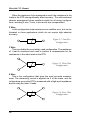
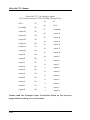
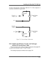
When using connection boxes with RTDs, care must be taken not to
introduce errors due to lead resistance. For this purpose two 0 V paths
are provided.
• Current Return should be used for measuring the current
flow to 0 V.
• 0 V itself should be reserved.
FITTING APPLICATION COMPONENTS
Series Components
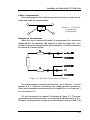
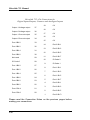
Component positions S1 to S37 (0.4 inch pitch) are available to
mount components in series with D-type pins 1 to 37. Only S1
and S37 are named on the PCB because of lack of space. However the numbering sequence is the same as that of the nearby
B1 to B37 components. To fit a component in series with, for
example, pin 10
• Place the component in the S10 position (level with B10),
• Solder it on the copper side,
• Cut the track under S10 at the point where it narrows.
The main application of series components is series protection
resistors. These could have any value from hundreds of ohms to
megohms depending on requirements.
Parallel Components
Component positions P0 to P17 (0.2, 0.3, 0.4 inch pitch) are provided to mount components across analogue inputs 0 to 15, 16
is the auxiliary input, 17 completes the pattern. Components can
be simply soldered into these positions.
Input Filters
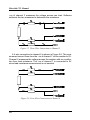
Low pass analogue input filters can be produced by fitting resistors in the 2 series elements of an analogue channel, and a
capacitor in the parallel element. For instance a filter can be
implemented on channel 1 by fitting resistors to S2 and S21 and
2.20