1
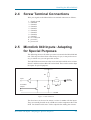
Microlink 840
User Manual
Manual Code: ML840-1.0
Issue Date: October 2011
Information in this manual is subject to change without notice. Updates are listed on our web
site at http://www.microlink.co.uk/techsupp.html
© Biodata Limited, 2011
10 Stocks Street
Manchester
M8 8QG
UK
Tel: 0161–834 6688
Fax: 0161–833 2198
E-mail: [email protected]
http://www.microlink.co.uk/
E-mail: [email protected]
http://www.windmillsoft.com/
Table of Contents
Table of Contents
1 Introduction
1.1
2 Installing the Microlink 840
2.1
2.1
2.2
2.3
2.4
2.5
2.6
Installing the Software
Installing the Microlink 840 on an Ethernet or Wi-Fi Network
The Microlink’s Lights
Screw Terminal Connections
Microlink 840 Inputs: Adapting for Special Purposes
Microlink 840 Digital Outputs
3 Configuring the Microlink 840
3.1
3.2
3.3
3.4
3.5
3.6
3.7
3.8
3.9
3.10
3.11
3.12
3.13
3.14
3.15
3.16
Running the ML840 Viewer Software
Establishing Communications with the 840
Setting the 840’s Clock
Setting the Epoch Length
Specifying Channels to be Analogue or Digital
Showing Real-Time Readings
Setting What Happens When an Alarm Occurs
Setting which data you want to store in the 840 Logger
Configuring Input Channels: Naming, Enabling, Scaling
and Setting Units
Performing Calculations
Making a Site Inactive
Setting where Data is Stored
Setting the Format of Data Files
Understanding Error Messages
Collecting Data
E-mailing Data and Reports
4 Fault Finding
4.1
4.2
4.3
4.4
No Route to Host Error
Can the Software Contact the Logger?
Calculated Channels aren’t being Logged
TCP-IP Timeout
Microlink 840 User Manual
2.1
2.1
2.1
2.2
2.2
2.4
3.1
3.1
3.1
3.4
3.4
3.4
3.8
3.8
3.11
3.12
3.14
3.15
3.16
3.16
3.17
3.17
3.21
4.1
4.1
4.1
4.1
4.2
I
Introduction
1
Introduction
The culmination of 30-years experience of designing data acquisition and
control systems, the Microlink 840 logger is our most versatile unit yet.
You can use it anywhere on an Ethernet network, or over the Internet, and
can…
1.
Monitor analogue transducers, for example pressure, temperature,
force, voltage and 4-20 mA current.
2.
Monitor Digital Sensors, for example flow meters.
3.
Monitor Utility Meters, for example electricity and gas meters.
4.
Monitor machines, for example recording percentage on/off times and
counting items produced.
5.
Monitor digital status, for example count switch closures.
6.
Control digital outputs.
7.
Count totals, frequency, periods, pulse widths and elapsed time.
8.
Save minimum, maximum and averaged values.
Logged data is exported as text files. You can also export it as xml files, Energy Lens compatible files or send it directly to a MySQL database.
Microlink 840 User Manual
1.1
Installing the Microlink 840
2
Installing the
Microlink 840
2.1
Installing the Software
1.
Run the setup.exe program.
2.
The software is normally installed into the:
C:\Program Files (x86)\Windmill Software\Windmill\
folder (where c: is the drive on which Windows is running). Two
other folders are created,
c:\windmill\setups\for details of the program settings and
c:\windmill\data\for your data files
2.2
2.3
Installing the Microlink 840 on an
Ethernet or Wi-Fi Network
1.
Connect your Microlink to a network-enabled PC over Ethernet. You
can use a crossover cable to make a direct connection, or connect
through a hub via normal UTP Ethernet cables.
2.
For Wi-Fi networks use an Ethernet cable to connect the Microlink to a
Wi-Fi router.
3.
Allow 10 seconds for the Microlink 840 to boot-up.
4.
From the Windows Start menu, choose the Windmill Software program group. Select ML840 Viewer. See the next chapter for details of
using the ML840 Viewer software to configure your Microlink
The Microlink’s Lights
The Microlink 840 has two lights labelled Busy and Power. The Busy light
comes on when the software talks to that Microlink 840 and remains on until the software talks to another Microlink. If you only have one Microlink
840 then the light will remain permanently on.
The Power light is on when the Microlink is powered-up.
The Microlink’s Lights
2.1
Installing the Microlink 840
2.4
Screw Terminal Connections
Wire your signals to the Microlink screw terminal connectors as follows.
1 - Signal ground
2 - channel 0
3 - channel 1
4 - channel 2
5 - channel 3
6 - channel 4
7 - channel 5
8 - channel 6
9 - channel 7
10 - no connection
11 - power 0V
12 - power 12V
2.5
Microlink 840 Inputs: Adapting
for Special Purposes
The following notes are for when you want to customise the Microlink 840
unit. This may have been done at the factory for you, or may not be necessary, in which case you can ignore this section.
The 840 PCB has an area next to the screw terminal to which series resistors
S0 to S7 and bias resistors B0 to B7 can be fitted. These can be used to adapt
the inputs for special purposes.
UP
3V3
Bx
Sx
Input
Processor
Output
Screw
Terminal
Cut
Bx
0V
DOWN
Figure 2.1 Microlink 840
The S resistors can be used to mount a resistor in series with the inputs.
They are normally shorted out by a PCB trace on the component side of the
PCB. You should cut this trace with a scalpel before adding the resistors.
Microlink 840 Inputs: Adapting for Special Purposes
2.2
Installing the Microlink 840
The B resistors can be fitted between a fixed PCB hole and either the UP or
DOWN holes as marked on the PCB. Fitting to the UP hole connects the
resistor to 3.3 Volts. Fitting to the DOWN hole connects it to the 0 V.
2.5.1
Contact Closure Inputs
Add a Bx resistor in the UP position. A closed contact will then read ‘0’
whilst an open contact will read ‘1’. We recommend a 1 kOhm resistor, but
anything similar will work.
2.5.2
Analogue Inputs: Changing the input
Range
The Microlink 840 accepts analogue inputs in the range 0–3.3 V. You can
change this by adding resistors.
You can divide down Analogue Inputs to the 3V3 input range of the 840 by
adding an Sx resistor and a Bx resistor in the DOWN position. The ML840
Setup program has a facility for calculating the values of the two resistors.
The two resistors in total should present a load which your input signal
is capable of driving. For example for 0-10V input signals you can try Sx =
20 kOhm, Bx (to down) = 9.76 kOhm. The signal is divided by
(20+9.76)/9.76 = 3.
2.5.3
Current Loop Inputs
You can convert a 4-20 mA current signal to a voltage by adding a resistor
in the Bx DOWN position. A value of 150 Ohms will produce a 3 Volt
signal at 20 mA.
2.5.4
Negative Input Voltages
If your input signals go negative by more than a few volts then the output
drivers will start to protect themselves and unwanted currents will flow
which will affect analogue readings on all channels. The driver chip IC3 is
fitted in a socket so if you are not using outputs you can simply remove it. If
you have some outputs then you can remove it from its socket and bend outwards those pins which are inputs only. Pin 18 is associated with Input 7,
Pin 17 - Input 6, etc to Pin 11 - Input 0.
Microlink 840 Inputs: Adapting for Special Purposes
2.3
Installing the Microlink 840
2.6
Microlink 840 Digital Outputs
12 V in
12 V in
1K0
Output pin
Figure 2.3 Microlink 840 LED Drive Output
12 V in
12 V relay
Output pin
Figure 2.2 Microlink 840 Relay Drive Output
Microlink 840 Digital Outputs
2.4
Configuring the Microlink 840
3
Configuring the
Microlink 840
Use the ML840 Viewer program to configure the Microlink 840. Amongst
other things, this lets you:
• Set up communications between the computer and the Microlink
(Section 3.2).
• Choose whether each channel is a digital input (counter), digital
output or analogue output (Section 3.5).
• Choose the type of counter: totalling, frequency, period, pulse
•
•
•
•
•
•
3.1
3.2
width, elapsed time (Section 3.5.2).
Set alarms (Section 3.7)
Set which data is to be stored (Section 3.8)
Change input channel names and units (Section 3.9).
Perform calculations on the data (Section 3.10)
Set where data is to be stored and the format of the logged data
(Sections 3.12 and 3.13)
Choose how often to collect data from the Microlink
(Section 3.15).
Running the ML840 Viewer
Software
1.
Make sure your Microlink 840 units are connected and switched on.
2.
From the Windows Start menu, choose the Windmill program group
and select ML840 Viewer.
Establishing Communications
with the 840
The first time you use the ML840 Viewer you should connect directly to the
Microlink and make sure that you can communicate with it. You can then
Establishing Communications with the 840
3.1
Configuring the Microlink 840
create a “site” and in future connect to that. The site holds the configuration
details for all the Microlinks on your network.
3.2.1
Connecting to Directly to Microlink 840
Logger
Do this when you want to:
• Check the settings of the ML840, for example the clock and
enabled channels
• Find the IP address of the unit
• Change the IP to a temporary IP address so that your PC can
communicate with it
• Make a permanent change to the IP address of the ML840.
When connecting directly to ML840, you can only have one Microlink on
the network. (Otherwise you may change the IP addresses of all the units on
the network. This would result in you being unable to contact any of them.)
It is best to use a crossover lead and to have a one-to-one connection with
the ML840.
3.2.2
1.
From the opening ML840 Viewer screen, choose the Connect to a
Windmill Site menu then select Direct to an Ethernet Logger.
2.
Type in the IP addresses, for example 192.168.1.61 and port 47471,
and click Connect. The Logger details box appears where you can configure channels, alarms and so on.
3.
If the software can communicate with the Microlink the BUSY light
will come on the unit.
Connecting to a Site
A site allows you to communicate with one or more Microlinks. These must
all have the same IP addresses. For different IP addresses you will need to
create multiple sites.
By default the system has one site, called ML840. This assumes one
Microlink 840 is connected at IP address 192.168.1.61 and port 47471. See
the next section for details of creating other sites.
3.2.3
1.
From the opening ML840 Viewer screen, choose the Connect to a
Windmill Site menu then select To an existing site.
2.
Click the Connect button. The Logger Details box appears for you to
configure channels, alarm and so on.
Creating a Site
By default the system has one site, called ML840, but you can create others.
Establishing Communications with the 840
3.2
Configuring the Microlink 840
1.
In ML840 Viewer, choose Site Manager. This holds the information
about each place where data is collected. For example the name of the
site, the communications link, the number and names of the data collection locations within the site and any special processing of data
from each location.
Figure 3.1 Creating a Site
2.
Click the Add a New Site button and type a name for the site.
3.
The File Prefix ties together many sites: the data for all sites with an
identical File Prefix will be collected as a single overall site. For example, you may have Microlink 840s gathering data in three locations. If
the File Prefix is S1, then all logged data will be sent to the same file
under directory name S1.
4.
The Installation Date defines the date from which the software will
scan for accrued data. It defaults to today's date, but you can enter any
date you wish.
5.
Enter the correct IP address, for example 192.168.1.61:47471
6.
When using a modem to transfer data, enter the modem's dial-up number. Include only figures: not spaces, commas, etc. Remember to allow
for additional dialling numbers, such as those required for external
lines.
7.
Save the site information and the ML840 Viewer stores the details in a
text file called sites.xml.
You can now connect to the site you have created as detailed in the previous
section.
Establishing Communications with the 840
3.3
Configuring the Microlink 840
3.3
Setting the 840’s Clock
1.
Connect to a Windmill Site: the Logger Details box appears. Choose
the Logger Settings tab.
2.
The Clock is the date and time which is currently set inside the ML840
Logger. To set this to match the computer, press the Reset button.
The Microlink maintains a count of seconds: it has no internal knowledge
of days or months. The data and time that data is collected by the software is
calculated within the PC from the Microlink seconds count.
As time in the Microlink logger is reset according to the PC time you
should ensure that all computers that you might use to collect data are on the
same time.
3.4
Setting the Epoch Length
The epoch length is the time in seconds over which data is logged, and maximum, minimum and average readings are calculated. The default epoch is
3600 which means that the count will be logged every hour.
1.
Connect to a Windmill Site and choose the Logger Settings tab.
2.
Enter a minimum value: we recommend that the value for the Epoch
length should be 60 seconds or longer.
3.
Enter a maximum value: the longest Epoch that can be used is 32000
seconds (9 hours).
As the Epochs progress they are numbered. The count will be stored at the
end of the current epoch. You can’t edit this setting.
You can have different epoch lengths for each channel.
When the maximum number of epochs is reached, the earliest data will be
overwritten. Data should have been collected by WM Collect before this
happens. The maximum number depends on how many channels of data
you are collecting, but for 8 hardware channels plus maximum, minimum
and average values, it can store 933 epochs. See Section 3.8 for details of
setting which data is stored.
3.5
Specifying Channels to be
Analogue or Digital
A Microlink 840 has eight hardware channels, each of can be configured as
one of
• Digital Input - for example to monitor a contact closure
Specifying Channels to be Analogue or Digital
3.4
Configuring the Microlink 840
• Digital Output - for example to provide a logic signal to switch
other equipment
• Analogue Input - for example a 0-3.3 V DC voltage.
3.5.1
Setting a Channel to be Digital or
Analogue
1.
Connect to a Windmill Site and and from the Logger Details box
choose the Input/Output tab.
2.
The software shows the channels as numbered 0-7. Each channel can
be either digital or analogue. Digital channel numbers start from 0 and
go up. Analogue channel numbers start from 7 and go down.
3.
To change a digital channel to an analogue channel, click the highest numbered digital channel and change its settings.
4.
To change an analogue channel to a digital channel, click the lowest
numbered analogue channel and change its settings.
Figure 3.2 ML840 Viewer: Choosing how to use your Channels
3.5.2
Configuring a Digital Input/Counter
Channel
1.
From the Logger Details box choose the Input/Output tab.
Specifying Channels to be Analogue or Digital
3.5
Configuring the Microlink 840
2.
Click a digital channel number (from 0 upwards). The Configure
Channels box appears.
Figure 3.3 Configuring a Digital Input Channel
3.
Choose from 5 counter types and set the appropriate options, detailed
below.
Total (Accumulating) Counts
• Choose whether to start from 0 at power-up, or restore the last
count a power-up
• Choose whether to count on the change from low to high or from
high to low
• Specify a minimum on and off time to avoid counts from contact
bounce
Frequency Measurement
Frequency measurement counts the number of pulses within a time period.
(Hertz is the number of pulses within one second.)
Specify a Gate Time - the time over which pulses are counted, so that
frequency can be measured.
The gate time should be long enough to count sufficient pulses to give a
good resolution of the frequency. The longer the gate time, though, the less
often the frequency can be updated. For example, if the pulse rate is 100 Hz,
then a gate of 0.1 seconds will count 10 pulses giving a resolution of only
10%, while a gate time of 1 second will count 100 pulses.
Specifying Channels to be Analogue or Digital
3.6
Configuring the Microlink 840
The firmware in the 840 can also record
• The maximum frequency in the recorded epoch
• The minimum frequency in the recorded epoch
• The averaged frequency over the epoch
These options are controlled through the Data Storage page.
Period Measurement
Period measurement counts the time between pulses. You can use it, for example, to record the total time a machine was on. The firnware in the 840
can also record:
• The maximum period between pulses in the recorded epoch
• The minimum period in the recorded epoch
• The averaged period over the epoch
• These options are controlled through the Data Storage page.
3.5.3
Configuring an Analogue Channel
There is one setting you can change when configuring an analogue channel
here: the input range.
Figure 3.4 Configuring an Analogue Channel
• By default, the 840 can handle inputs in the range 0 to 3.3 V DC.
• For signals larger than this you can use resistance dividers to set
the range to be, for example, 0-5 V or 0-10 V. You can ask for
this to be done before the Microlink 840 leaves the factory, or can
add resistors to the Microlink yourself. See Section 2.5 for details.
If necessary enter the appropriate division factor.
• For bipolar signals, for example +5 V, see Section 2.5.
Specifying Channels to be Analogue or Digital
3.7
Configuring the Microlink 840
3.6
Showing Real-Time Readings
You can see current readings with the ML840 Viewer program.
1.
Connect to a Windmill Site and choose the Readings tab from the
Logger Details box. The values from all the channels on this logger are
shown, even if they are not enabled for storage in the logger.
There can up to 32 channels on a logger. These come from the 8 hardware
channels—which can be digital input, digital output or analogue input
channels—and minimum, maximum and averaged data for each channel.
• Digital inputs can be:
Counting inputs—either 16- or 32-bit counters
Frequency or period counting
• process value—current frequency or period
• maximum value
• minimum value
• Digital outputs
• Digital status—the momentary value of the 8 digital input lines
• Analogue inputs can be:
process value—the current analogue input value
n
average—the average over the epoch time
n
minimum—the lowest value in this epoch
n
maximum—the highest value in this epoch
n
n
n
3.7
Setting What Happens When an
Alarm Occurs
You can set two alarms on each hardware channel: typically a warning and
a critical alarm. On an alarm condition a message can be sent to a computer
on the network and a digital output switched, perhaps to sound a buzzer or
turn on a light.
1.
Connect to a Windmill Site and choose the Alarms tab from the
Logger Details box.
Setting What Happens When an Alarm Occurs
3.8
Configuring the Microlink 840
2.
Click Alarm 0 to enable the first set of alarms, for example the critical
alarms. The Alarm Edit box appears.
Figure 3.5 Specifying what happens on alarm
3.
Tick the Alarm Enable box.
4.
Choose how you will be alerted to the alarm: by switching a digital
output, sending a message to a computer or both.
5.
When switching a digital output choose to switch it on or off when an
alarm occurs. Select Alarmed state 0 or 1. When 0 or off a high voltage
is sent to the inputs. When 1 or on a low voltage is sent to the inputs.
6.
You can choose to reset the alarm once the alarm condition ceases, or
to make it stay on.
7.
You can insert a delay between an alarm threshold being crossed and
an alarm sounding: useful in reducing the instances of false alarms.
For example if you were monitoring the temperature of a hospital
freezer, it may temporarily cross an alarm threshold when somebody
opened it, only to recross it moments later when they closed the
freezer. You only want to be alerted when the temperature remains
over the limit for a certain time.
8.
When you choose to send a message to a computer on the network, you
need to enter the Destination IP address of the computer. If the computer is on a different subnet, you will also need the subnet mask and
Setting What Happens When an Alarm Occurs
3.9
Configuring the Microlink 840
Gateway IP address. You can ignore the Name Server IP address. Your
target computer needs a small Windmill application running on it to
receive the message.
9.
3.7.1
When you are happy with your settings press the Apply button. You
can now set up alarm conditions on individual channels.
Setting Alarm Levels on Invidual Channels
When you’ve set what happens when an alarm occurs, you can configure
the alarms for individual channels.
1.
In the Alarm tab (Figure 3.5) click the channel’s number. The Alarm
Input box appears.
Figure 3.6 Specifying alarm conditions
2.
Tick Enable Input for Alarm.
3.
Choose whether an alarm is to be raised when this channel goes into an
alarm state, or whether a combination of channels need to be in alarm.
Select either Direct Alarm or Combination Alarm.
4.
Choose the source of the alarm. Only options available with your
chosen channel are shown.
5.
Set the level which, when crossed, causes an alarm condition. For an
analogue input the value you enter here will change to the nearest actual value that the Microlink’s analogue-to-digital converter will
produce.
6.
Choose whether an alarm occurs when the channel is above (>) or
below (<) this level.
Setting What Happens When an Alarm Occurs
3.10
Configuring the Microlink 840
3.8
Setting which data you want to
store in the 840 Logger
You can choose how much data is stored in by the 840 Logger. The more
parameters you save the more space may be taken up. If, say, you were storing all possible data and logging every hour you would have around a
month’s data stored. Remember that you also regularly read the 840 using
WM Collect software and save the data to the computer’s hard drive.
1.
Connect to a Windmill Site and choose the Data Storage tab from the
Logger Details box.
Figure 3.7 Setting which data you want to store in the Logger
2.
For counters, choose 16- or 32-bit counts. 16-bit allows counting up to
65000; 32-bit allows counting to over 16 million. 16-bit counts occupy
less space in the Logger, so data can be saved over a longer period
without being overwritten. For 16-bit set Count LSW to 1 and Count
MSW to 0: click the current value to change. For 32-bit set both Count
settings to 1.
3.
To store frequency or period values, click the Process box so a 1 is
shown. If you are unable to do this, and an x remains, you haven’t enabled that channel for frequency or period counting. Section 3.5.2
discusses how to do this.
4.
To save the state of digital inputs at the end of the epoch (logging
interval), tick Record the Status of digital inputs.
Setting which data you want to store in the 840 Logger
3.11
Configuring the Microlink 840
5.
You can also store maximum, minimum and average values over the
epoch for each channel.
6.
You can store the last analogue input value of the epoch by enabling
process, but it is probably more useful to store the average, maximum
and minimum values.
Note that if you update the storage allocation in the Microlink Logger as
detailed above, you will lose all existing saved data.
After updating you may need to change engineering units, names, etc for
the channels. Do this in the Input Channels box, Section 3.9, and click the
Read Channels from Hardware button.
3.9
Configuring Input Channels:
Naming, Enabling, Scaling
and Setting Units
In Section 3.5 we discussed choosing whether a hardware channel was an
analogue or digital input or output. For input channels, you can also choose
a name for the channel, whether or not the channel is enabled, any scaling to
be applied to the readings from that channel and the units of the channel:
volts, Hz, counts, etc. These details are used by the other Windmill
programs such as WM Collect and SetupIML.
1.
Choose the Site Manager menu and select the Input Channels tab.
Configuring Input Channels: Naming, Enabling, Scaling and Setting Units
3.12
Configuring the Microlink 840
Figure 3.8 Configuring input channels
2.
If you have changed which data is stored (Section 3.8), click the Read
Channels from Hardware button.
3.
To re-name a channel, click its name and type in a new one.
4.
To disable or enable a channel click its code number and its status will
be changed. You can also click its current Enabled setting to change.
5.
To change the units of measurement, click the current units and type in
a new one. When you change the units you will also need to tell the
software how to scale the data so that it is displayed accurately in the
new units.This uses the formula:
New Engineering Units = Scale x Standard Units + Offset
For example: if a pressure transducer produces 0 volts output at
1 atmosphere, rising smoothly to 10 volts at 5 atmospheres, then to
obtain the reading in atmospheres you need:
scale = 0.4
offset = 1.0
Similarly, temperatures can be displayed in Fahrenheit by setting scale
= 1.8, offset = 32; and voltages can be displayed in millivolts by setting
scale = 1000, offset = 0.
Configuring Input Channels: Naming, Enabling, Scaling and Setting Units
3.13
Configuring the Microlink 840
If you plan to use the standard Windmill software suite to collect or display
data in real-time (eg Windmill Logger, Chart or DDE Panel), select IMS
File from the menu bar. You can then load this setup file into the other
Windmill programs.
3.10 Performing Calculations
You can perform calculations on the data and store the results in the logged
data file. Your calculations are saved as it they were normal hardware
channels.
3.10.1 Defining Calculations
1.
Choose the Site Manager menu and select the Calculated Channels
tab.
Figure 3.9 Defining Calculations
2.
Click the Add New button. The Channel Details area appears.
3.
Type a name for the Calculated channel into the Channel Name box.
Make this different to any other calculated or hardware channels.
Spaces will be removed.
Performing Calculations
3.14
Configuring the Microlink 840
4.
Construct a formula for calculating the new value. To add a channel to
the formula click the Import Hardware Channels button. Now doubleclick a channel to add it to the formula. For the formula to work hardware channels need to be enclosed in square brackets. This is done
automatically if you double click a channel in the list.
You can construct more complicated formulae if needed. The Operators / * - + are supported. The order of operations is: () / * - +. It is best
to use brackets () to avoid any ambiguity about the order of
calculation.
5.
Type the units of your calculation: volts, bars, counts or visits for
example.
6.
Press Accept to save the new calculated channel.
7.
Repeat for as many calculated channels as you need, then press OK.
Deleting Calculated Channels
To delete a calculated channel, select it from the Defined Channels list and
press the Delete button. If you are part way through creating a new channel,
and have not yet pressed the Accept button, you can just press the Cancel
button. The Clear button removes the formula, leaving you with a blank
box, but does not remove the channel.
Turning Off Calculations
If you wish to temporarily turn off calculations, but don’t wish to delete all
the ones you have entered, you can do so. Select the Program Setup menu.
If the Additional Reports box is not ticked, your calculated channel settings
will be ignored. When the Additional Reports box is ticked, daily and
weekly totals are created according to your calculated channel definitions.
The Results of the Calculation
When a complete set of data for a particular day has been read from the
Microlink 840s, the calculated channels file is processed and the calculation results appended to the file. Weekly files containing the daily totals are
also prepared.
3.11 Making a Site Inactive
If a site is not collecting data, for example an experiment has been closed
for maintenance or an IP connection is not available, you can mark the site
as inactive. Data will not then be collected from that site.
1.
In the VT Viewer choose the Site Manager menu.
2.
In the Site Details tab, tick Site is Offline and will not be accessed.
Making a Site Inactive
3.15
Configuring the Microlink 840
3.12 Setting where Data is Stored
By default the data is stored in
c:\windmill\data\
and setup files in
c:\windmill\setups
You can move the windmill folder elsewhere, but you need to tell the
ML840 Viewer where it is.
1.
In the opening ML840 Viewer screen, choose Program Setup.
2.
In the General tab, enter the new location in the File Locations box.
Figure 3.10 Program Setup Options
If Data in Monthly Directories is ticked then the daily data files will be
placed in a folder called:
C:\windmill\data\[site_prefix]\mmyy\
where mmyy is the current month and year
otherwise all the files will appear in:
c:\windmill\data\[site_prefix]\
3.13 Setting the Format of Data Files
Data is saved in tables in text files. You can also save data as xml files and
export it to a MySQL database. Data is saved at regular intervals or epochs.
To choose how to save data:
Setting the Format of Data Files
3.16
Configuring the Microlink 840
1.
In the opening ML840 Viewer screen, choose Program Setup.
2.
In the General tab, look for the Data Tables section.
3.
The epochs per day is the number of rows in the daily table. (This may
not be the same as the number of epochs the logger will store during
the day.)
A value of 24 gives hourly counts or readings in the table.
A value of 96 gives counts or readings every 15 minutes in the table.
4.
You can choose the number of decimal places you want to see in the
data file. For example, for 3 decimal places use 0.000. For data which
will be an integer, like counts, use 0.
5.
If you are using calculated channels then tick the Additional
Reports box.
6.
You can choose to have data files saved in xml files, as well as in text
files. Tick the Create xml data files box.
7.
The tables in the data file usually start at midnight and contain a day’s
data. However, if you want to start logging at a different time you
can do so. Just enter how long after midnight you want to start into the
Data time offset box.
3.14 Understanding Error Messages
1.
Connect to a Windmill Site and choose the Errors tab from the
Logger Details box.
2.
Zeroes mean no errors. For others click on Interpret and a box
explaining the meaning of the error appears.
3.15 Collecting Data
You can regularly download blocks or epochs of data from the Microlink
840 using the WM Collect utility. Data will be saved as text files, and optionally can be saved as xml files and exported to a MySQL database.
You use WM Collect to automatically collect stored data from the
Microlink at regular intervals. You can either run it continually, or—if you
just want to collect data daily, weekly or monthly—run it as a Windows
schedule.
You can also log and display data in real-time using the Windmill suite of
software. To do this make sure that you select IMS file from the Site
Manager window (Section 3.9). Data will be saved in text files.
Collecting Data
3.17
Configuring the Microlink 840
3.15.1 Scheduling Data Collection with WM
Collect
Use the WM Collect program to automatically collect data from the
Microlink 840s at regular intervals. For example, you could collect data every 5 minutes or every hour. For counts, you can choose to reset the counter
when you collect data.
1.
In the opening ML840 Viewer screen, choose Program Setup.
2.
Choose the Schedules tab and click Add New Event.
3.
Choose how often to upload the data, and whether to reset counts when
you do so.
WM Collect must be running continuously to in order to collect the data.
Make sure that WM Collect doesn’t automatically shut itself down.
4.
Choose the Options tab.
5.
Clear the Apply box.
3.15.2 Collecting Data Daily, Weekly or Monthly
Use Windows Task Manager or Scheduled Tasks (depending on your version of Windows) to schedule automatic data collection daily, weekly or
monthly. For example, in Windows 7 you will find Scheduled Tasks in:
Start > All Programs > Accessories > System Tools > Task Scheduler.
Look for the WM Collect program and click the Next button. Choose
whether to collect data daily, weekly or monthly. Select the time for collection. Set WM Collect to run once then close. The command to initiate a
download is the path of wmcollect.exe. For example
C:\Program Files\Windmill Software\wmcollect.exe
When running WM Collect as a scheduled task you should tell it for how
long to run before shutting down.
1.
Choose the Program Setup menu and select the Options tab.
2.
Enter a running time and tick the Apply box.
3.15.3 Extra Saved Data
You can save real-time counts and place completed daily files to a Postbox
directory.
1.
Collecting Data
In the opening ML840 Viewer screen, choose Program Setup.
3.18
Configuring the Microlink 840
2.
Choose the Options tab.
Figure 3.11 Setting some data collection options
3.
Tick Save real time counts if you want the WM Collect to keep an
updating file of real-time data values.
4.
Tick Completed day files to Postbox if you want daily files to be stored
in the data Postbox directory, as the daily file is completed. Use this if
you have another application that is collecting data from the daily files,
and you do not want to be re-reading partially complete files.
The daily data file will be stored in \windmill\data\postbox\ directory.
5.
Tick Upload new settings from Postbox if you want a new settings file
(*.xml) can be placed in the setups Postbox, and will be uploaded to
the ML840 unit after the next data collection event.
The program looks for the files in the \windmill\setups\postbox\
directory.
3.15.4 Storing Data in a MySQL Database
WM Collect stores data in text files and, optionally, xml files. You can tell
it to also send data directly to a MySQL database.
1.
In the opening ML840 Viewer screen, choose Program Setup.
2.
Choose the MySQL tab. A separate database called iml is created.
Within iml 4 tables are created:
• The iml_channels_table holds the names of the channels (for
logged data) that will be found in the main iml_data_table.
The fields are:
n
site_prefix
n
channel_name.
Collecting Data
3.19
Configuring the Microlink 840
n
n
sensor_error
display_group - associates this channel into a group so
summaries for the group can be made
• The iml_daily_table holds summary data for each completed day.
The fields are:
site_prefix
n
channel_name.
n
channel_status
n
reading_date - the date for this set of data.
n
sum - the total of each channel for the day
n
count - number of epochs in the day (for calculating means
n
etc
max - maximum value for any epoch during the day.
n
min - minimum value for any epoch during the day.
n
• The iml_data_table holds data values for each channel at each
epoch time for each site are found here.
The fields are:
site_prefix
n
channel_name.
n
channel_status
n
reading_time - the end of the epoch to which this data value
n
belongs.
reading_raw - the value actually read from the logger - may
n
later be adjusted to a different reading_value.
n
reading_value - the data value to be used for this epoch.
n
upload_time - the date-time at which this data value was
uploaded from the logger
• The iml_sites_table holds the names and other details of each site
in the ML840 system.
The fields are:
n
site_prefix
n
site_name - the full name of the site.
n
site_port - the communications port for this site (e.g. the IP
address.
n
last_upload - the date-time of the last dat upload from this
site. Used to check for sites where communications fail.
n
logger_error - the last error code received from the logger.
You will normally pull data from the iml_data_table into your own database for use with other data sets you are collecting. To keep the
iml_data_table relatively small, it is possible to delete data values after a retention period of 1 or more months.
3.
Collecting Data
Enter the IP address of the server where the mySQL database is to be
found into the MySQL database server box. If it is on this computer,
3.20
Configuring the Microlink 840
then either give the IP address of the computer, if it is on a network, or
127.0.0.0 if it is standalone.
4.
Enter the version of the MySQL driver installed on this PC into the
Driver box. The current version is: {MySQL 5.1 ODBC Driver}
5.
Enter the login details for the MySQL system into the Username and
Password box.
6.
In the Data retention box - data values older than the number of months
specified, will be deleted from the iml_data_table, as new data is acquired. Use 0 if you want data to be kept in the iml_data_table.
3.15.5 Using the Windmill Suite to Display and
Log data in Real-Time
1.
Select Site Manager and go to the Input Channels tab.
2.
Choose the IMS File menu option. This generates an ims file for this
Microlink 840. The file will be called: prefix_L0_yymmdd.ims and
saved in the windmill setups directory.
3.
When you start a Windmill program like Logger, DDE Panel or Chart,
from its File menu choose Load Hardware Setup and choose the prefix_L0_yymmdd.ims file. For more details of using any of these
programs click its Help button.
3.16 E-mailing Data and Reports
You can e-mail data and settings files to people.
1.
Choose the Program Setup menu and select the Communications
tab.
E-mailing Data and Reports
3.21
Configuring the Microlink 840
Figure 3.12 Emailing reports
Mail report to:
Copy mail to:
Mail from:
SMTP server:
Password:
E-mailing Data and Reports
E-mail address of to where you want the report sent.
E-mail address of to where you want a copy sent.
E-mail address from which the report will be sent.
The outgoing mail server from which the e-mail
will be sent.
Your e-mail account’s password.
3.22
Fault Finding
4
Fault Finding
4.1
No Route to Host Error
This error occurs on Ethernet systems either because there is no physical
connection between a Logging unit and the PC, or because there is no
network enabled on your PC. Check
• the cabling
• that the Microlink 840 is powered up
• that the local area connection settings on your PC are correct
4.2
Can the Software Contact the
Logger?
When the software talks to a Logger module, the module's busy light comes
on. It remains on until the software talks to another Logger. The busy light
is on the back panel of a boxed Logger, and on the Logger module's front
panel in a rack-based system. If you only have one Logger then the light
will remain permanently on.
The busy light is useful for diagnosing problems. If you remove the power
supply from the unit and then reconnect it, the busy light will be off. If it
goes on when you talk to the unit then you can see to which one you are
talking and confirm that the software has found it.
4.3
Calculated Channels aren’t being
Logged
In VT Viewer select the Program Setup menu. If the Additional Reports
box is not ticked, your calculated channel settings will be ignored. When
the Additional Reports box is ticked, daily and weekly totals are created
according to your calculated channel definitions.
Calculated Channels aren’t being Logged
4.1
Fault Finding
4.4
TCP-IP Timeout
If you receive a TCP-IP timeout error, increase the timeout setting.
TCP-IP Timeout
1.
In the ML840 Viewer choose the Program Setup menu and select the
Communications tab.
2.
Increase the Timeout setting.
4.2
Index
Index
accumulating counter
see total counter
additional reports 3.15, 3.17
alarm 3.8-10
analogue input 2.3, 3.5, 3.7-8, 3.12
average 3.12
busy light 2.1
calculated channels 3.14-15, 3.17
channels 3.4-7
clock 3.4
collecting data 3.17-20
Communications tab 3.21-22
Connect Direct to an Ethernet logger 3.1-3
Connect to a Windmill site 3.2-3
connections 2.2
contact closure inputs 2.3
counter 3.5, 3.7-8, 3.11
accumulating 3.6
frequency 3.6, 3.11
period 3.7, 3.11
total 3.6
creating a site 3.2-3
current signals 2.3
data files 3.16
data format
MySQL 3.19
text 1.1
xml files 3.17
Data Storage tab 3.11-12
decimal places 3.17
digital input 3.4-6, 3.8, 3.11
digital output 2.4-5, 3.8
digital status 3.8, 3.11
Direct to an Ethernet Logger 3.2
e-mailing data and reports 3.21-22
engineering units 3.13
Microlink 840 User Manual
epoch 3.4, 3.11, 3.17
errors 3.17
Ethernet 2.1
file format 3.16
MySQL 3.19
text 1.1
folder 2.1
format of data files 3.16
frequency counter 3.6, 3.11
General tab 3.16-17
hardware channels 3.4-7
IMS file 3.21
inactive channel 3.15
Input Channels tab 3.12, 3.21
input range 2.3
Input/Output tab 3.5
IP address 3.2
lights
busy 2.1
power 2.1
location of data files 3.16
Logger Details 3.5, 3.8
Logger Settings tab 3.4
logging interval
see epoch
maximum 3.12
minimum 3.12
MySQL database 3.19
naming channels 3.12-13
negative input voltages 2.3
Options tab 3.18-19
outputs 2.4
period counter 3.7, 3.11
power light 2.1
process 3.8
Program Setup 3.16
i
Index
Program Setup menu 3.17-19, 3.21
Readings 3.8
rows in the table 3.17
sample period
see epoch
Schedules tab 3.18
scheduling data collection 3.18
screw terminal connections 2.2
Site Details tab 3.15
Site Manager menu 3.3, 3.12, 3.14-15, 3.21
status 3.8, 3.11
time to start logging 3.17
total counter 3.6
trouble-shooting 4.1-2
units 3.13
Wi-Fi 2.1
WM Collect software 3.17
xml files 3.17
Microlink 840 User Manual
ii