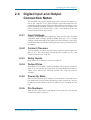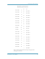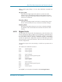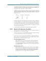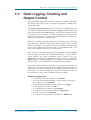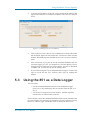
1
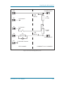
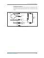
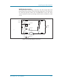
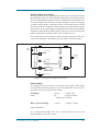
Microlink 851 User Manual Biodata Limited Manual Code: 851-1.0 Issue Date: June 2012 Information in this document is subject to change without notice. For updates see http://www.microlink.co.uk/techsupp.html Biodata Limited 2012 10 Stocks Street Manchester M8 8QG UK Telephone: +44 (0)161 834 6688 Facsimile: +44 (0)161 833 2190 E-mail: [email protected] http://www.microlink.co.uk/ http://www.windmillsoft.com/ Table of Contents 1 Introduction 1.1 2 Installing the Microlink 851 2.1 2.1 2.2 2.3 2.4 2.5 2.6 2.7 2.8 2.9 The Microlink 851's Light Analogue Input Connection Notes Analogue Input Pin Connections Table Digital Input and Output Connection Notes Counter Connection Notes Digital Input/Output and Counter Pin Connections Table Connecting the 851 to an Ethernet Network Specifications The 59x Screw Terminal Units 3 Installing and Configuring the Windmill Software 3.1 3.2 3.3 3.4 What is Windmill Software? Getting Started with Windmill Installing Windmill Software Telling the Software about the Devices you have Connected 2.1 2.1 2.4 2.6 2.7 2.7 2.9 2.9 2.11 3.1 3.1 3.1 3.1 3.2 4 Real-Time Data Acquisition and Control on the PC 4.1 4.1 4.2 4.3 Introduction Configuring Hardware Channels with SetupIML Data Logging, Charting and Output Control 5 Using the ML851 Viewer Software 5.1 5.2 5.3 5.4 5.5 5.6 Running the ML851 Viewer Software Changing the 851’s IP Address Using the 851 as a Data Logger Setting the 851’s Clock Setting the Epoch Length Setting the Resolution and Integration Time of the A-D Converter 4.1 4.1 4.7 5.1 5.1 5.1 5.2 5.3 5.4 5.5 5.7 5.8 5.9 5.10 5.11 5.12 5.13 5.14 5.15 5.16 Starting Logging Configuring the Hardware Returning to Real-Time Logging on the PC with Windmill Changing the State of Digital Output Channels Resetting a Counter Balancing Strain Gauge Bridges Choosing where to send Alarm Notifications Connecting to a Site Setting where Data is Stored Collecting Data Microlink 851 User Manual 5.5 5.6 5.7 5.7 5.8 5.8 5.8 5.10 5.11 5.12 II Introduction 1 Introduction The Microlink 851 lets you: • Measure temperature, strain, pressure, voltage and current through • • • • 16 analogue input channels Switch up to 32 digital outputs Monitor up to 32 digital inputs Count events or measure frequency with up to 8 counters Log data from all channels up to 10 times a second The Windmill Software lets you: • • • • • Configure the Microlink 851 Log data Chart data Control outputs Send data to Excel and other Windows programs Optional Windmill modules are available, for example to display process mimics or send sequences of control actions. See http://www.windmillsoft.com/ for more information. The rest of this Manual tells you: • About the Microlink 851 unit and how to connect your signals (Chapter 2) • How to install the Windmill software (Chapter 3) • How to use the standard Windmill software with the 851 unit to log and chart data in real-time (Chapter 4) • How to use several Microlink 851s as data loggers on a network with the ML851 Viewer software (Chapter 5). Microlink 851 User Manual 1.1 Installing the Microlink 851 2 Installing the Microlink 851 The 851 has two 37-way connectors: one for analogue connections and one for digital and counter connections. If you prefer you can make your connections to screw terminals, using one of the optional Microlink 59x range of external units. You will also need a 59x unit if you plan to interface transducers like thermocouples or strain gauge bridges. 2.1 The Microlink 851's Lights The Microlink 851 has green and red lights labelled PWR and BUSY. Neither of these will come on until you have installed the Windmill software. PWR This is lit when the Microlink has been powered on. BUSY This is lit for the duration of each communication. 2.2 Analogue Input Connection Notes The Microlink 851 provides 16 differential analogue inputs. It also has an auxiliary channel which is reserved for special inputs such as cold junction measurement or bridge excitation monitoring (used with thermocouples and strain gauges). It uses an integrating analogue-to-digital converter, where the integration time and resolution are under software control (set in the Windmill ConfIML program, which starts automatically when you install the software). At regular intervals Windmill uses a stable on-board reference voltage for recalibration. Use ConfIML to set this recalibration interval. Microlink 851 User Manual 2.1 Installing the Microlink 851 2.2.1 Differential Inputs All the inputs are differential: for each input signal there are two signal wires. The measurement is the difference in voltage between the two wires. The two signals go into separate high-impedance amplifiers which monitor the voltage between the input and ground. The outputs of the two amplifiers are then subtracted to give the difference between the + and – inputs. For small signals differential inputs are much better than single-ended inputs, because the subtraction of the voltages on each of the input wires means that any voltage common to both wires is removed, so reducing noise. It is important to remember that the voltages at both inputs must be within the amplifier operating range. A classic error is to connect a battery between positive and negative inputs with no other connection. Although the difference between the inputs is well defined, the actual voltage at each input could be anything. Connecting one end of the battery to the 0 V input, either direct or via a resistor, would solve the problem. The 0 V of the Microlink 851 is connected to computer earth, which is usually connected to the mains earth. When making your connections you should follow this policy. a If your signal source is “floating”, i.e. has no reference to mains earth, then you must provide a reference by connecting one end of it to the 0 V input, either direct or via a resistor. The resistor could have any value up to several MΩ. However large values could cause 50 Hz problems if your signal source has much leakage to earth. b If your signal source is itself earthed then you should connect only positive and negative inputs. You should make no connection to the Microlink 851 earth. 0 V (pin 19) a. Floating Signal Source Channel input MICROLINK b. Earthed Signal Source Channel input MICROLINK Figure 2.1 For floating signals you need to connect one end of the signal to the 0 V input on pin 19 Microlink 851 User Manual 2.2 Installing the Microlink 851 2.2.2 Input Voltage Range The Microlink 851 operates correctly with input voltages in the range ±11 V. The inputs will reject voltages which are common to both positive and negative inputs. These common mode voltages could be as large as 13 V. 2.2.3 Maximum Input Voltage The input multiplexers are protected against dc voltages of 33 V above the power supply. This means +48 V if the computer is switched on, +33 V if it is switched off. If the over-voltage is transient then protection extends as far as +300 V. When a voltage above the power supply is applied to the unit its protection mechanism comes into action, and this draws some current from the signal source. This effect can be a problem when the computer is switched off as it now draws current from any signal. This current is limited by 4K7 resistors. Extra series resistors can be added to reduce this fault current. 2.2.4 Unconnected Inputs You can leave unused inputs unconnected, but if you attempt to read from these unconnected inputs do not expect to get 0 V. They could be any value. If another connected channel has recently been read, the unconnected input will return a similar value. This is not crosstalk. It occurs because the input capacitance of the amplifier is charged to the voltage of the previous channel and has little incentive to change when connected to an open circuit. 2.2.5 Auxiliary Input This input has all the facilities of the other sixteen. In Windmill software it is reserved for measuring cold junction temperatures with thermocouples or excitation voltage in bridge circuits. If using a 593 thermocouple input unit or a 594 bridge input unit, the auxiliary input is automatically connected as required by the software. Use with 593 Thermocouple Input Unit When used with this unit the auxiliary input is automatically connected to the cold junction sensor. This is an RTD (resistance temperature device) with 0.8 milliampere flowing through it. If inputs are unconnected the thermocouple break detection circuitry will cause them to read positive full scale. Pins 18 and 37 (–15 V and +15 V) provide a power supply for the 593—don’t connect any other signals to these pins. For more on connecting thermocouples, see Section 2.9.3. Use with 594 Bridge Input Unit When used with this unit the auxiliary input automatically measures the excitation voltage connected to the 594. For more on connecting strain gauges, see Section 2.9.4. Microlink 851 User Manual 2.3 Installing the Microlink 851 2.3 Analogue Input Pin Connections Table Make your connections to the analogue 37-way D connector as detailed on the next page. Microlink 851 User Manual 2.4 Installing the Microlink 851 Microlink 851 - 16 Analogue Inputs Pin Connections for 37-Way D Plug (Wiring View) 19 0V 18 –15 V 17 – Auxiliary 16 – Input 15 15 – Input 14 14 – Input 13 13 – Input 12 12 – Input 11 11 – Input 10 10 – Input 9 9 – Input 8 8 – Input 7 7 – Input 6 6 – Input 5 5 – Input 4 4 – Input 3 3 – Input 2 2 – Input 1 1 – Input 0 +15 V 37 + Auxiliary + Input 15 + Input 14 + Input 13 36 35 34 33 + Input 12 30 + Input 11 31 + Input 10 30 + Input 9 29 + Input 8 28 + Input 7 + Input 6 + Input 5 27 26 25 + Input 4 24 + Input 3 23 + Input 2 + Input 1 + Input 0 22 21 20 Please read the Connection Notes on the previous pages before making your connections. Microlink 851 User Manual 2.5 Installing the Microlink 851 2.4 Digital Input and Output Connection Notes The Microlink 851 provides digital input to the computer and output control by the computer. Its 32 general purpose input and output lines are arranged in 4 groups or ports. Each port can be either input or output (set using the Windmill SetupIML program). All ports power-up as inputs. The ports are referred to as Port 0 to Port 3. Port 3 also functions as 8 event counters, detailed in the next section. 2.4.1 Input Voltages All inputs are high impedance CMOS type. They are TTL and 5 V CMOS compatible. Input Voltages should be within the range 0 to 5 V. Higher Voltages can be dealt with by the addition of resistor networks. This can be conveniently done on a 590 unit. Input protection can be provided in a similar manner. 2.4.2 Contact Closures You can interface to contact closures using a resistor to tie the input to either 5 or 0 V. The contact then switches the line to either 0 or 5 V. The resistor can be fitted to a 590 unit. 2.4.3 Noisy Inputs Input Filters can be fitted to a 590 unit if required. 2.4.4 Output Drive The outputs are TTL and 5 V CMOS compatible. They can drive 15 LSTTL loads. You can increase the output drive by using additional transistors, which can be fitted to the 590 unit. Currents of 1 amp can easily be switched. 2.4.5 Power-Up State The 851 unit will power-up as all inputs. If you intend to use the card to control outputs then you may want to define logic states at power-up. This can be done by resistors which tie the lines to either 0 or 5 V, mounted on a 590 unit. 2.4.6 Pin Numbers Make the I/O connections to the digital 37-way connector. See the Pin Connections Table on page 2.8. Microlink 851 User Manual 2.6 Installing the Microlink 851 2.5 Counter Connection Notes The Microlink 851 unit provides eight 16-bit event or frequency counters. These are located on Port 3 of the digital I/O connector. If you are using counters, use the Windmill SetupIML software to set Port 3 as an input only. The 851 unit monitors the state of the 8 input lines once every millisecond and maintains a count for each of them. It does this whether or not you intend to use the lines as counters. You can still read Port 3 as a normal digital input, even if you are also using it to count. 2.5.1 Input Voltages See Section 2.4.1 for safe voltage levels. 2.5.2 Count Inputs A valid count is declared if the input is low for 100 µseconds then high for two milliseconds. This gives a theoretical maximum count speed of 5 kHz. 2.5.3 Pin Numbers Make the counter connections to Port 3 of the Digital Connector. The counter pin numbers are on page 2.8. 2.6 Digital Input/Output and Counter Pin Connections Table The pin numbers given on the next page are those for the digital 37-way D socket. The analogue input pin numbers are on page 2.5. Microlink 851 User Manual 2.7 Installing the Microlink 851 Microlink 851 - Pin Connections for Digital Inputs/Outputs and Counters Port 3 Bit 0 Port 3 Bit 2 Port 3 Bit 4 Port 3 Bit 6 Port 1 Bit 0 Port 1 Bit 2 Port 1 Bit 4 Port 1 Bit 6 16 Port 3 Bit 5 15 Port 3 Bit 7 14 Port 2 Bit 1 13 Port 2 Bit 3 12 Port 2 Bit 5 11 Port 2 Bit 7 10 Not used 9 Not used 8 Port 1 Bit 1 7 Port 1 Bit 3 6 Port 1 Bit 5 5 Port 1 Bit 7 4 Port 0 Bit 1 3 Port 0 Bit 3 2 Port 0 Bit 5 1 Port 0 Bit 7 30 29 28 27 26 25 24 23 Port 0 Bit 2 22 Port 0 Bit 6 Port 3 Bit 3 31 Port 0 Bit 0 Port 0 Bit 4 17 34 32 Not used Port 3 Bit 1 35 Port 2 Bit 2 Not used 18 36 33 Port 2 Bit 6 0V 37 Port 2 Bit 0 Port 2 Bit 4 19 21 20 Please read the Connection Notes on the previous pages before making your connections. Microlink 851 User Manual 2.8 Installing the Microlink 851 2.7 2.8 Connecting the 851 to an Ethernet Network 1. Connect your Microlink 851 to a network enabled PC. You can use a crossover cable to make a direct connection, or connect through a hub via normal UTP Ethernet cables. 2. For Wi-Fi networks use an Ethernet cable to connect the Microlink to a Wi-Fi router. 3. Allow 10 seconds for the 851 to boot-up. 4. Use the Windmill ConfIML software configure the 851, as detailed in Chapter 3. Specifications 2.8.1 Microlink 851 Unit Dimensions (mm) Maximum number of 851s Memory 2.8.2 180 x 120 x 40 Limited only by the number of addresses on the network 65000 scans Analogue Inputs Number of inputs 16 differential Maximum safe input voltage Computer on ±48 V Computer off ±33 V Transient ±300 V Ranges (set from software) ±10 V, ±1 V, ±100 mV, ±10 mV Common mode range ±13 V Relative accuracy of ranges gain = 1000 ±0.1% gain = 1, 10, 100 ±0.05% A-D performance (set from software) Resolution (bits) Integration Time (msec) 12 2.5 13 5 14 10 15 20 16 40 18 160 Maximum speed of sampling 10 scans per second subject to integration time Maximum linearity error ±0.02% Input impedance 100 MΩ Microlink 851 User Manual 2.9 Installing the Microlink 851 2.8.3 Digital Inputs and Outputs Maximum number of inputs Maximum number of outputs Power-up state Voltage Inputs Compatibility Range Voltage Outputs Compatibility Drive 2.8.4 TTL and 5 V CMOS 0 to 5 V TTL and 5 V CMOS 15 LSTTL loads Counters Maximum number of counters Resolution Type of counters Gate time for frequency Maximum frequency Compatibility Input voltage range 2.8.5 32 32 all inputs 8 23 bits Event (totalise) Frequency 1 or 10 seconds 5 kHz TTL and 5 V CMOS 0 to 5 V Software Operating system Windows 10, 8, 7 (64- or 32-bit), Vista, XP, 2000, 98 or later Microlink 851 User Manual 2.10 Installing the Microlink 851 2.9 The 59x Screw Terminal Units The Microlink 59x range provides screw terminals for the Microlink 851, allowing signals to be permanently wired. These boxed 59x units sit next to the Microlink 851s. Some of the 59x range allow transducers like thermocouples and strain gauge bridges to be monitored by the 851. Extra facilities are available when components are fitted, such as protection from high voltages. There are 4 units in the range. 590 590-8A 593 594 Screw Terminals Screw Terminals and Current Measurement Screw Terminals and Temperature Measurement Screw Terminals and Strain Measurement The 59x range is optional, so you can ignore the rest of this chapter if you have bought just the Microlink 851 and Windmill package. 2.9.1 590 Unit—Screw Terminals The 590 is a boxed screw terminal card. Extra facilities are available with this card, including: • • • • • • • • • noise filtering, input protection from high voltages, higher voltage inputs than normal, contact closure inputs, ac inputs, biasing to ground, external current source switching, programmable resistance, special output ranges. Connection The 590 unit has space for 3 rows of 18 screw terminals. The row nearest the front panel is connected to pin 19 of the analogue D connector on the front of the Microlink. This pin is connected to 0 V. The other 2 rows are connected to pins 1–18 and 20–37 as indicated by the small figures by the terminals. Fitting Application Components Series Components Component positions S1 to S37 (0.4 inch pitch) are available to mount components in series with D-type pins 1 to 37. Only S1 and S37 are named on the PCB because of lack of space. However the numbering sequence is the same as that of the nearby B1 to B37 components. To fit a component in series with, for example, pin 10 Microlink 851 User Manual 2.11 Installing the Microlink 851 • Place the component in the S10 position (level with B10), • Solder it on the copper side, • Cut the track under S10 at the point where it narrows. The main application of series components is series protection resistors. These could have any value from hundreds of ohms to megohms depending on requirements. Parallel Components Component positions P0 to P17 (0.2, 0.3, 0.4 inch pitch) are provided to mount components across analogue inputs 0 to 15, 16 is the auxiliary input, 17 completes the pattern. Components can be simply soldered into these positions. Input Filters Low pass analogue input filters can be produced by fitting resistors in the 2 series elements of an analogue channel, and a capacitor in the parallel element. For instance a filter can be implemented on channel 1 by fitting resistors to S2 and S21 and a capacitor to P1. Typical values would be 10 KΩ and 1 µF. These would produce a cut off frequency of about 8 Hz. Microlink 851 User Manual 2.12 Installing the Microlink 851 2.9.2 590-8a Unit—Screw Terminals with Current Measurement The 590-8A is a boxed milliamp current detection card, arranged as 8 current and 8 voltage inputs. The same extra facilities are available with this card as with the 590. 2.9.3 593 Unit—Screw Terminals with Temperature Measurement The 593 is an isothermal box specialised for thermocouple monitoring of temperatures. It includes a cold junction sensing RTD with an associated constant current source (0.8 milliamps). The RTD determines the temperature at the termination point. This reference temperature is used with the analogue input channel’s voltage reading to calculate the temperature at the thermocouple junction. The Windmill software automatically connects the cold junction to the auxiliary channel and compensates for it. It reads the channel directly, showing the cold junction temperature in Celsius. Protection from high voltage inputs is provided when series resistors are added. Noise problems can be solved by fitting an input filter and broken thermocouple leads can be detected. The cold junction sensing circuitry is located between the two leftmost rows of screw terminals. This circuitry is connected by the PCB to the auxiliary channel. Bias resistors are fitted to produce a small current through the thermocouples. This allows thermocouple break detection. 2.9.4 594 Unit—Screw Terminals with Strain Measurement The 594 is a boxed 16 bridge inputs card, which enables the 851 unit to monitor strain gauge bridges and balanced bridges such as pressure transducers. For strain gauges you need an external excitation voltage, which can supply sufficient current to keep all the bridge circuits energised. Four sets of 16 screw terminals give + and – excitation and + and – signals for each of 16 bridges. Two 1 kΩ termination resistors are mounted in half bridge configuration whilst high quality 350 and 120 Ω resistors can be provided for the completion of quarter bridges. The auxiliary channel of the 851 unit monitors the excitation voltage. The A-D converter is suitable for direct measurement of voltage imbalance provided you choose a high resolution. When monitoring a bridge input, the Windmill software automatically reads excitation voltage and performs the bridge calculation to produce a reading in microstrain. You can set a zero reference level and monitor changes relative to that level. Microlink 851 User Manual 2.13 Installing the Microlink 851 With the 594 unit you can configure each input channel for any of the following inputs. voltage input quarter bridge half bridge half bridge full bridge full bridge full bridge single strain gauge tensile + compressive strain gauge normal + transverse strain gauge 2 tensile + 2 compressive gauges 2 normal + 2 transverse gauges tensile normal + compressive normal + tensile transverse + compressive transverse gauges Figure 2.2 shows the general arrangement of the 594. For each input channel (0–15) there are 5 screw terminals. These are arranged in 5 rows labelled, 0V, +EX , —EX, +IN, –IN, with channel number printed by each terminal. Common to all channels are the POWER INPUT terminals and two precision resistors connected across the power supply to form a half bridge. The power input terminals are directly connected to the auxiliary channel of the 851. Windmill software reads this channel to measure the excitation voltage for use in the bridge equations. Each channel has associated with it 2 link mounting positions and one resistor position. These are: RX Position for mounting a quarter bridge completion resistor QX Link to short out the quarter bridge completion resistor HX Link to connect the half bridge to the –IN of channel X Microlink 851 User Manual 2.14 Installing the Microlink 851 +EX +POWER INPUT +in aux channel +IN -IN + in channel x - in channel x Hx -EX HB1 1K Ohm -in aux channel Rx 1K Ohm HB2 -POWER INPUT Qx OV 0V Microlink Common PER CHANNEL COMMON TO ALL CHANNELS Figure 2.2 General Arrangement of 594 Microlink 851 User Manual 2.15 Installing the Microlink 851 Full Bridge Connection The figure below shows a full bridge connection. The QX quarter bridge link must be fitted to connect the –POWER INPUT to the –EX. Four wires are needed to connect your bridge and the earth is available for a cable screen. +POWER INPUT +EX Strain Gauges +IN + in channel x POWER -IN SUPPLY - in channel x Hx -EX Rx -POWER INPUT screen Qx OV Figure 2.3 594 Full Bridge Connection Microlink 851 User Manual 2.16 Installing the Microlink 851 Half Bridge Connection This figure shows a half bridge connection. The HX and QX links must both be fitted. The HX link connects the half bridge to the –IN of the channel, whilst the QX link connects the –POWER INPUT to the –EX. Three wires are needed to connect your bridge and the earth is available for a cable screen. +POWER INPUT +EX Strain Gauge +IN + in channel x POWER SUPPLY -IN - in channel x Hx -EX Rx -POWER INPUT screen Qx OV Microlink 0V Figure 2.4 594 Half Bridge Connection Microlink 851 User Manual 2.17 Installing the Microlink 851 Quarter Bridge Connection The figure below shows a quarter bridge connection. The HX link connects the half bridge to the –IN. The RX bridge completion resistor must be fitted. This resistor should be a high precision, low temperature coefficient device. Its value should be the same as the nominal resistance of your strain gauge, 120 and 350 Ω being the commonest values. In other applications it should be chosen to balance the bridge near the centre of your measurement range. For instance if you are making precise RTD measurements around ambient temperature then 100 Ω would be suitable. If however you were monitoring higher temperatures a suitably larger value would be chosen. It is normal practice when making a quarter bridge connection to take all 3 wires to the transducer. This balances out the effects of lead resistance. +POWER INPUT +EX Strain Gauge +IN + in channel x POWER SUPPLY -IN - in channel x Hx -EX Rx -POWER INPUT screen Qx OV Microlink 0V Figure 2.5 594 Quarter Bridge Connection Power Supply The bridges must be powered by an external power supply. The voltage used should be chosen by the user to suit his application. The current requirement can then be calculated as follows: Full Bridge where current = voltage / Rg Rg = gauge resistance usually 120 or 350 Ω Half or Quarter Bridge current = voltage / (2*Rg) Typical Examples 16 * 120 Ω quarter bridges with 10 V excitation. These use 42 mA per bridge making a total of 0.67 amps. Microlink 851 User Manual 2.18 Installing the Microlink 851 16 * 350 Ω full bridges with 10 V excitation. These use 28 mA per bridge making a total of 0.45 A. Connection of Power Supplies Power supplies are often floating devices, i.e. they are not referenced to mains earth. If this is the case a connection must be made from Microlink 851 0 V to the power supply negative. This can easily be done on the 594. If this is not done, the bridge output voltages may be beyond the range of the 851 input amplifiers and false readings will result. If several 594 units are used on a common power supply, each should be given its own connection to the power supply. This minimises the current flowing in any particular power supply wire, and so reduces voltage drop in the wires. Microlink 851 User Manual 2.19 Installing and Configuring the Windmill Software 3 Installing and Configuring the Windmill Software 3.1 What is Windmill Software? Windmill is a ready-to-run suite of applications for data acquisition and control. You can be up and running in very little time as no programming is required. The standard suite includes real-time data logging, charting and output control applications. You can also transfer data directly into third-party applications like Microsoft Excel or Access. Other Windmill modules are available—see the Windmill Software catalogue for details http://www.windmillsoft.com/. 3.2 3.3 Getting Started with Windmill 1. Install the software onto the hard disk. 2. Use the ConfIML program to add the 851 to your Windmill system. 3. Use the SetupIML program to choose how you want to use the 851’s input and output channels: set alarm levels, choose transducer types, rename channels and so on. 4. Use the Windmill Logger, Chart, DDE and Control Panels to display data and send digital output values. Installing Windmill Software 1. 2. Run the setup.exe program. The software is normally installed into the: c:\program files\windmill software\ folder (where c: is the drive on which Windows is running). Two other folders are created, c:\windmill software\setups\ Microlink 851 User Manual 3.1 Installing and Configuring the Windmill Software for details of the program settings and c:\windmill software\data\ for your data files 3. 3.3.1 When installation is complete the Windmill Configuration program, ConfIML, automatically starts. This asks for details of your hardware. See Section 3.4 for details. Upgrading From Earlier Versions of Windmill You can run Windmill alongside earlier versions of the software. Once you are happy that you no longer need a previous copy of Windmill simply run its “Uninstall” program to delete it. 3.3.2 Running Several Copies of Windmill Unless you have bought a multiple licence, you are only permitted to run one copy of the software at any one time. Please contact your supplier if you require a multiple licence. 3.4 Telling the Software about the Devices you have Connected The Windmill Configuration program, ConfIML, records the details of your data acquisition hardware. It will run at the end of the installation process, and you should run it again from Windows whenever your acquisition hardware changes—for example when you install additional units. Figure 3.1 Running ConfIML The first thing you need to do is press the Add button to include your 851 unit. Microlink 851 User Manual 3.2 Installing and Configuring the Windmill Software 3.4.1 Adding New Hardware The Add IML Hardware dialogue lists the acquisition and control devices for which you have installed drivers. Select the Windmill 851 Ethernet Logger and press the Add button. This will take you to the Hardware Settings dialogue (Section 3.4.2). 3.4.2 Changing Hardware Settings ConfIML needs to know some information about your 851 unit. Press the Help button or see below if in doubt about the answers. Figure 3.2 ConfIML: Adding the 851 to your System Which Type of Transducer Connection Unit is Attached? There are three options. Which you choose depends on the 59x units you have connected. (The 59x units let you, for example, monitor current, thermocouples or strain gauges.) None/General Purpose Choose this if you: • are not using a 59x unit, • are using a 590 screw terminal voltage unit, or • are using a 590-8A screw terminal current unit. Thermocouple Choose this if you are using a 593 thermocouple terminal unit. This monitors the temperature of connections, which is essential when using thermocouples. You can use channels not required for thermocouples for general voltage measurement. Microlink 851 User Manual 3.3 Installing and Configuring the Windmill Software Strain Bridges Choose this if you are using a 594 strain gauge bridge connection unit. This monitors an external bridge excitation supply so that strain gauge outputs can be converted into readings in microstrain. Again, you can use channels not required for strain for general voltage measurement. Select the Integration Time (Resolution) This allows you to select the trade off between speed, precision and noise rejection. Seven settings are available—the slower the speed, the better the precision and the more random noise is averaged out. The exact speeds and resolutions vary with the computer, transducer type and so on, but the following table gives some typical figures. Setting Typical Speed Voltage Resolution 12-bit 80 reads/sec 5 mV in ±10 V 13-bit 64 reads/sec 3 mV in ±10 V 14-bit 48 reads/sec 1.5 mV in ±10 V 15-bit 32 reads/sec 0.8 mV in ±10 V 16-bit 16 reads/sec 0.4 mV in ±10 V 18-bit 6 reads/sec 0.1 mV in ±10 V Settings from 15-bit to 18-bit will be effective at removing 50 Hz mains noise as these integrate over one or more complete mains cycles. The resolution figures show the ability to detect small changes. The absolute accuracy will depend on several factors including your transducers. Interval Between Automatic Recalibrations (in Minutes) This selects how frequently the software pauses to perform a recalibration of the Microlink 851 using its stable on-board reference voltages. This will cancel any errors introduced by temperature or power supply changes since the last recalibration, but can take up to a second to complete. During this time, no readings may be taken. You can vary the interval from 1 to 1440 minutes (24 hours), but every 20 minutes is generally sufficient. IP Address The default IP address of an 851 is 192.168.1.61. Change this to match the actual address of your 851. To change the IP address of your 851, use the ML851 Viewer program (Section 5.2). When you save your IP address in the Viewer, it will automatically update the ConfIML settings. Microlink 851 User Manual 3.4 Installing and Configuring the Windmill Software 3.4.3 851 Devices After making your choices and pressing OK, the ConfIML Summary window appears showing your 851 as three hardware devices: 851 analogue inputs, 851 digital ports and 851 counters. 3.4.4 Adding the ComIML Serial Instrument Handler You may also like to add Windmill’s generic serial instrument driver. This lets you communicate with most instruments over RS232, RS485, Modbus and Ethernet: including the 851. Click the Add button and choose ComIML Serial Instrument Handler. 3.4.5 Setting the Working Directory When you use Windmill you will create two types of files, those which hold data and those which hold the Windmill programs’ settings. You can specify a default folder in which to store these files— known as the Working Directory. Initially the working directory is set to wherever you installed Windmill. To change this, press the Directory button. Choose a new directory and press Save. Windmill will create two subdirectories under this choice, called setup and data. All the Windmill settings will be stored in “setup” and all the data you collect stored in “data”. 3.4.6 Saving the Settings Save your settings and they will be used every time you run Windmill. You do not need to run ConfIML again, unless you add more units or want to change the settings. After closing ConfIML start the SetupIML program and choose how you wish to use the hardware. Refer to the next chapter and SetupIML’s program Help for details. 3.4.7 The Software Signal Generator In addition to data acquisition and control hardware, ConfIML lists the Software Signal Generator. This is a special driver which simulates a device with seven channels, each channel producing a different signal. No special hardware is required—the data values are produced by calculation. The Software Signal Generator lets you experiment and practise with Windmill, without being concerned about the hardware To install the signal generator you first need to add it to the list of devices. In the ConfIML Summary window press the Add button (Section 3.4.1). Select Software Signal Generator and again press the Add button. You’re taken to the Hardware Settings dialogue (Section 3.4.2) where you can choose options for five of the channels. Press the Help button in this dialogue for more information on the signal generator. Microlink 851 User Manual 3.5 Installing and Configuring the Windmill Software 3.4.8 The IML Device Icon Whenever you run a Windmill program one or more IML Device icons will appear. Different icons identify different hardware drivers, software signal generators and so on. The Windmill applications can’t run without these, so don’t close them whilst using Windmill. Microlink 851 User Manual 3.6 Real-Time Data Acquisition and Control on the PC 4 Real-Time Data Acquisition and Control on the PC 4.1 Introduction This chapter explains how to use the standard Windmill software suite for real-time data acquisition and control on your PC You can use the Microlink 851 to monitor voltages. With additional Microlink 59x units, you can also monitor currents, thermocouples and strain gauge bridges. If you wish to measure resistance or pH, please contact Biodata for advice. Use the Windmill SetupIML program to specify how each input or output channel is to be used. Before starting Windmill make sure your 851 is plugged into the Ethernet network and, if you are using a 59x unit, that it is plugged into the 851’s analogue connector. You should also have used the ConfIML software to add the 851 to your system, as detailed in the previous chapter. 4.2 Configuring Hardware Channels with SetupIML SetupIML is the Windmill program that lets you save libraries of setup files, each holding details about how you want to use individual channels. 1 Start SetupIML and choose to create a new setup. 2 Type a name and description for your setup. An 851 is shown as three devices in SetupIML: Analogue Inputs, Digital Inputs and Counters. Choose one from SetupIML’s Device menu. Double-click a channel to configure it. Full details of using SetupIML are in its program Help. Microlink 851 User Manual 4.1 Real-Time Data Acquisition and Control on the PC 4.2.1 General Purpose Analogue Input Connector The input channels are numbered 0 to 15. Using SetupIML you can configure each channel as follows: • enable or disable • re-name • set to a specific input range or allow the software to pick the range automatically • give a new units name, scale factor and offset • set alarm levels. 4.2.2 Thermocouple Input Connector The signal inputs are numbered 0 to 15. Using SetupIML you can configure each channel as follows: • enable or disable • choose one of six common thermocouple types for automatic linearisation to Celsius, or choose to read raw voltage • re-name • set to a fixed range or allow the software to pick the range automatically • give a new units name, scale factor and offset • set alarm levels. Channel 16 is normally disabled, but if enabled you can use it to read the cold junction reference temperature at the screw terminals. This can be used to linearise the voltages from other types of thermocouple in some external software such as a spreadsheet. 4.2.3 Strain Gauge Bridge Connector The signal inputs are numbered 0 to 15. Using SetupIML you can configure each channel as follows: • enable or disable • set to one of six bridge configurations (see below) or set to read raw voltage • re-name • set to a fixed range or allowing the software to pick the range automatically • set to a gauge factor • if transverse strain is being measured, specify Poisson’s ratio for the material under test • set alarm levels. See also the Special commands described on page 4.3. The supported bridge configurations are: Microlink 851 User Manual 4.2 Real-Time Data Acquisition and Control on the PC Quarter bridge One active gauge and three fixed resistors. Half bridge One gauge measuring tensile strain (+E), one measuring compressive strain (–E), and two fixed resistors. Half bridge One gauge measuring normal strain (+E), one measuring transverse strain (–vE), and two fixed resistors. Poisson’s ratio must be specified. Full bridge Two gauges measuring tensile strain (+E) and two measuring compressive strain (–E). Full bridge Two gauges measuring normal strain (+E) and two measuring transverse strain (–vE). Poisson’s ratio must be specified. Full bridge One gauge measuring normal tensile strain (+E), one measuring normal compressive strain (–E), one transverse tensile strain (+vE), and one compressive transverse strain (–vE). Poisson’s ratio must be specified. In all these cases the answer is reported directly in microstrain. Channel 16 is normally disabled but if enabled it can be used to read the bridge excitation voltage, which must be the same for all channels, and is used in the calculations. 4.2.4 Special Hardware Commands The channel dialogue boxes will have the “Special” button enabled. This allows access to the following commands: Recalibrate Forces an immediate recalibration of the whole board. This is in addition to the periodic calibration cycles which happen automatically (described in Section 3.4.2). Cal_Interval Displays the time between automatic calibration cycles, as selected in ConfIML (described Section 3.4.2). Resolution Displays the resolution and integration time for this card, as selected in ConfIML (described Section 3.4.2). Show_Cal_Data Used only during manufacturer’s test procedures. Microlink 851 User Manual 4.3 Real-Time Data Acquisition and Control on the PC When a strain gauge bridge is in use, three additional commands are available: Set_Zero_Now This reads the bridge output ratio and uses it as the zero strain reference level. All subsequent readings will be changes in strain relative to that point, until another special command is issued or the software is closed down. Describe_Offset This shows the bridge output level which is currently being used as the zero strain reference level (as a fraction of excitation voltage). Disable_Offset Resets the zero strain reference to zero volts, so absolute readings are obtained. This is the default state each time the software starts running. 4.2.5 Digital Ports The Microlink 851 unit provides four digital ports, each with 8 lines. You can use each port for input or output. You can explicitly control the choice, or it can be deduced automatically by the software. All ports start as inputs, but if any data is sent to a port by a Windmill program it immediately switches to output mode. Output lines can also be controlled by the alarm detection features of the input channels. This will cause the whole port to switch to output mode. You can also use port 3 for event counting—in which case you must set it as an input. The channels are numbered as follows: 0100 0101 0102 .. 0107 0108 0109 0110 0111 ... 0117 0118 0119 0120 etc Line 0 of port 0 Line 1 of port 0 Line 2 of port 0 ... Line 7 of port 0 Direction control signal for port 0 not used Line 0 of port 1 Line 1 of port 1 ... Line 7 of port 1 Direction control signal for port 1 not used Line 0 of port 2 In SetupIML you can replace the numbers with meaningful names. Microlink 851 User Manual 4.4 Real-Time Data Acquisition and Control on the PC By default, each channel is linked to a single line and the two digital states are called ON and OFF. You can change these names to more suitable ones, for example FAST and SLOW or OPEN and SHUT. SetupIML lets you group the lines within each port into multi-bit channels which are displayed or controlled as single values transferred via the first channel in the group. Multi-bit values can be chosen as binary, decimal or hexadecimal, e.g. Binary 11 1010 10001 11111111 Decimal 3 10 17 255 Hexadecimal 3 A 11 FF Channels 0108, 0118, 0128 and 0138 are the direction control signals for ports 0 to 3. When set to 0, the whole port is used for input; when 1, the port is used for output. These channels can be viewed and also altered, but they are normally disabled and must be explicitly enabled from SetupIML before use. As noted above, direction control can usually be sensed automatically by the software. Channel 0109, 0119 and 0129 are not used and cannot be enabled. 4.2.6 Event or Frequency Counters The Microlink 851 unit provides eight 16-bit event or frequency counters. The default names are 0200, 0201 to 0207. If you are using counters, use the Windmill SetupIML software to set Port 3—where the counters are located—as an input only. Double-click a counter channel and use SetupIML to change the names, enable or disable each channel and choose Accumulating Event Counter, Resetting Event Counter or Frequency Counter. Accumulating Event Count Each counter starts at zero and counts pulses on the corresponding input lines, to a maximum of 1,000,000. A counter can be reset to zero at any time by sending “0” to the channel using the AnalogOut or (optional) Graphics or Test-Seq programs. No other values can be sent to the counters. Resetting Event Count Starts again from zero after each reading. This shows the number of pulses since the last reading, but it can only be used where a single program is reading the counter. If several different programs were accessing the counter simultaneously, they would all be resetting it at different times, so the results would be unpredictable. Microlink 851 User Manual 4.5 Real-Time Data Acquisition and Control on the PC Frequency Counter In frequency mode you can choose a gate time of 1 or 10 seconds from the Input Range/Mode box. The 851 counts the number of cycles occurring at its count input during this gate time. SetupIML also lets you apply a scale factor and offset to the count. For example, when event counting if the pulses came from a flow meter which produced one pulse for each 50 millilitres, then a scale factor of 0.05 would give a reading in litres. Microlink 851 User Manual 4.6 Real-Time Data Acquisition and Control on the PC 4.3 Data Logging, Charting and Output Control The standard Windmill suite of software comprises: ConfIML; SetupIML; the display and control panels—AnalogOut, DigitalOut & DDE Panel; Logger and Chart. The display and control panels let you send data to, or display data from, any number of analogue and digital channels. Logger logs data to disk from up to 100 channels whilst Chart displays moving charts of data from up to 8 channels. For more channels, or different logging and charting speeds, simply run more instances of Logger and Chart. Full details of all these programs are given in their on-line Help files. Should you need more sophisticated analysis or presentation, you can share data with other Windows applications using dynamic data exchange (DDE). For example, you can process data as it’s collected using Microsoft Excel. See the DDE Panel program Help, or the Windmill web site at http://www.windmill.co.uk/excel/, for more details. There are many other optional programs in the Windmill range. Graphics lets you design and create your own Windmill displays— process mimics, wiring diagrams, bar charts, annunicator panels…whatever you wish. Test-Seq interprets a file of commands, and controls a test-rig accordingly. Replay replays a data file graphically. For details of other optional programs see http://www.windmillsoft.com/daqshop/software.html. The programs described above run on the PC and collect data from the 851 in real-time. You can instead use the 851 to log data internally and then the WM Collect software to collect the saved readings at regular intervals, every hour or every day for example. To set up the 851 to behave in this way use the ML851 Viewer software, detailed in the next chapter. Windmill Program Jobs • To implement unit-wide settings: use ConfIML • To set-up each individual channel—setting names, engineering units, alarms, etc: use SetupIML • To log analogue and digital data in real-time: use Logger • To chart data in real-time: use Chart • To control analogue outputs: use AnalogOut • To change the state of digital outputs: use DigitalOut • To reset a counter: use AnalogOut • To send data to other programs via DDE: Use DDE Panel Microlink 851 User Manual 4.7 Using the ML851 Viewer Software 5 Using the ML851 Viewer Software Up until now this Manual has described how to collect and display data in real-time from one Microlink 851, using the Windmill standard suite of software. This is the method of data collection most often used. However, you can also use the 851s to log data to their own memories. The data can then be collected by software at regular intervals. This is most useful when you have many 851s on a network. To setup up the 851s to work in this manner use the ML851 Viewer software. This also lets you set up several 851s on an Ethernet network. 5.1 5.2 Running the ML851 Viewer Software 1. Make sure your Microlink 851 units are connected and switched on. 2. Close any other Windmill programs that are open, for example ConfIML. 3. From the Windows Start menu, choose the Windmill program group and select ML851 Viewer. Changing the 851’s IP Address 1. Close any other Windmill programs that are open, for example ConfIML. 2. Make sure there is only one 851 on the network. (Otherwise you may change the IP addresses of all the units on the network. This would result in you being unable to contact any of them.) It is best to use a crossover lead and to have a one-to-one connection with the 851. 3. From the opening ML851 Viewer screen, choose the Connect to a Windmill Site menu then select Direct to an Ethernet Logger. Microlink 851 User Manual 5.1 Using the ML851 Viewer Software 4. To change the IP address of the 851, select Change the IP Address and type the new details, for example IP Address 192.168.1.61 and port 47471 Figure 5.1 Changing an 851’s IP Address 5.3 5. Click Connect. If the software can communicate with the Microlink 851 the BUSY light will come on the unit. If it doesn’t, make sure that all other Windmill programs and IML device icons are closed, then try again. 6. Once connected, if you plan to use the standard Windmill suite for real-time logging to a PC, you should now close the ML851 Viewer software and can ignore the rest of this chapter. Go back to Windmill ConfIML and you will see the new IP settings there. 7. If you will be using the 751s as independent data loggers, where readings are saved into the 751s’ memory, then carry on reading this chapter. Using the 851 as a Data Logger You can either: • Use the standard Windmill software suite (Windmill Logger, Chart, etc) to log and display data in real-time from the 851 on a PC, or • Use the 851 to log data to its own memory, and then regularly transfer files of collected data to the PC. For the former you use the standard Windmill software suite, detailed in the previous chapters. For the latter, use the ML851 Viewer software to set up the 851 as a Data Logger, and WM Collect to download data to a PC. Microlink 851 User Manual 5.2 Using the ML851 Viewer Software There are various settings and actions you can make when using the 851 as a data logger. 5.4 1. Set the 851’s clock to match that of the PC: Section 5.4. 2. Set the 851’s “epoch length”: Section 5.5. This is is the time over which data is logged in seconds and may be an integer or have an interval of 0.1, 0.2 and 0.5. 3. Change the resolution and integration time of the analogue-to-digital converter: Section 5.6. This allows you to select the trade off between speed, precision and noise rejection. Seven settings are available—the slower the speed, the better the precision and the more random noise is averaged out. 4. Start logging to the 851’s memory: Section 5.7. 5. Send settings to the 851 which you previously specified in SetupIML: Section 5.8. 6. Enable Windmill DDE Panel to show live data, even though you are using the 851 as a data logger: Section 5.9. 7. Reset counters, balance strain gauge bridges, change digital ouput states: Sections 5.10, 5.11 and 5.12. 8. Choose the computer where alarm notifications will be sent: Section 5.13. 9. Create a site, holding details of a collection of Microlink 851s: Section 5.14.1. Setting the 851’s Clock You can set the Microlink’s clock to match that of the PC to which it is connected. 1. Connect to a Logger or Site: the Logger Details box appears. Choose the Logger Settings tab. Microlink 851 User Manual 5.3 Using the ML851 Viewer Software Figure 5.2 Changing an 851 Logger’s Settings 2. The Clock is the date and time which is currently set inside the Microlink 851 Logger. To set this to match the computer, press the Reset button. This is used to determine when data is transferred to the PC. The Microlimk keeps a count of seconds. It has no internal knowledge of days or months. As time in the Microlink logger is reset according to the PC time, you should ensure that all computers that you might use to collect data are on the same time. 5.5 Setting the Epoch Length Data is logged at the end of every epoch. 1. Connect to a Logger or Site and choose the Logger Settings tab. 2. Enter the epoch length. This can be in whole seconds or 0.1, 0.2 or 0.5 seconds. You could not, for example, have an epoch of 1.5 seconds. As the Epochs progress they are numbered. The values will be stored at the end of the current epoch. You can’t edit this setting. When the maximum number of epochs is reached, the earliest data will be overwritten. Data should have been collected by the WM Collect software before this happens. Microlink 851 User Manual 5.4 Using the ML851 Viewer Software 5.6 Setting the Resolution and Integration Time of the A-D Converter This allows you to select the trade off between speed, precision and noise rejection. Seven settings are available—the higher the resolution, the better the precision and the more random noise is averaged out. However, the maximum speed is reduced. The exact speeds and resolutions vary with the computer, transducer type and so on, but the following table gives some typical figures. Setting Typical Speed Voltage Resolution 12-bit 80 reads/sec 5 mV in ±10 V 13-bit 64 reads/sec 3 mV in ±10 V 14-bit 48 reads/sec 1.5 mV in ±10 V 15-bit 32 reads/sec 0.8 mV in ±10 V 16-bit 16 reads/sec 0.4 mV in ±10 V 18-bit 6 reads/sec 0.1 mV in ±10 V Settings from 15-bit to 18-bit will be effective at removing 50 Hz mains noise as these integrate over one or more complete mains cycles. The resolution figures show the ability to detect small changes. The absolute accuracy will depend on several factors including your transducers. 1. From the Logger Settings screen, select the Integrator Resolution. (Note: if using standard Windmill programs for real-time data acquisition and control via the PC—Section 4.3—use the Windmill ConfIMLprogram to set the resolution and not the ML851 Viewer.) 5.7 Starting Logging 1. In the Logger Settings screen, click the Start Recording button. This will send the settings you specified with the SetupIML program (engineering units etc) to the 851 and start it data logging. 2. Alternatively, you can go to the IMS Files screen, detailed in the next section, tick “Start and new recording” and click the Go button there. (Note: if you are using the standard Windmill programs for real-time data acquisition and control via the PC—Section 4.3—use the Windmill Logger program to start data collection and not the ML851 Viewer.) Microlink 851 User Manual 5.5 Using the ML851 Viewer Software 5.8 Configuring the Hardware You should have already created at least one ims file with the SetupIML program (Chapter 4). This holds details about how you want to use the individual channels of the 851. For example, you may have two channel connected to thermocouples, five channels counting and eight channels controlling digital relays. With SetupIML you can set alarm levels, give channels meaningful names, specify engineering units, choose input ranges and so on. With ML851 Viewer software you can choose a setup file and send it to the 851 Logger. 1. Connect to a Logger or Site and choose the IMS Files tab. Figure 5.3 Configuring the Channels of an 851 2. Choose an IMS file to load into the 851 Logger. The contents of the currently selected IMS file are shown on the right. To see what this means go back to SetupIML where you can view, and change, the settings. If you are interested in deciphering the IMS file shown on the right, you can read about it in Issue 87 of our newsletter at http://www.windmill.co.uk/monitor87.html#IMS 3. When using the 851 to log data into memory, if you also want to display data in real-time on the PC you must enable the ComIML generic serial driver. Tick the Create a comIML ims file and Prepare the Windmill system to use comIML. You can now use the Windmill DDE Panel to show real-time readings whilst logging to the 851’s memory. Microlink 851 User Manual 5.6 Using the ML851 Viewer Software 4. Click the Go button to load the settings. To also start logging, tick the Start a New Recording box and then click Go. (Note: if you are using the standard Windmill programs for real-time data acquisition and control via the PC—Section4.3—use Windmill Chart, Logger or DDE Panel to send the hardware settings and not the ML851 Viewer.) 5.9 Returning to Real-Time Logging on the PC with Windmill If you decide you want to log and chart data, and control outputs, on the PC in real-time, you need to return to using the standard Windmill programs rather than logging to the 851’s memory. 1. As in the last section, Connect to a Logger or Site and choose the IMS Files tab. 2. Click the Prepare Windmill for SetupIML tab. This launches the SetupIML program and reconfigures the system. 5.10 Changing the State of Digital Output Channels 1. Connect to a Logger or Site and choose the Digout and Balance tab. Figure 5.4 Changing the state of digital outputs, resetting counters and balancing strain gauge bridges Microlink 851 User Manual 5.7 Using the ML851 Viewer Software 2. The digital ouput channels are listed n the left. Click a channel to change its state. Click the Set Digital Outputs to send the changed states to the 851 Logger. (Note: if you are using the standard Windmill programs for real-time data acquisition and control via the PC—Section 4.3—use the Windmill DigOut program to change digital output states and not the ML851 Viewer.) 5.11 Resetting a Counter 1. As discussed in the previous section, Connect to a Logger or Site and choose the Digout and Balance tab. 2. Click the counters you want to reset. 3. Click the Reset Selected button. (Note: if you are using the standard Windmill programs for real-time data acquisition and control via the PC—Section 4.3—use the Windmill AnalogOut program to reset a counter and not the ML851 Viewer.) 5.12 Balancing Strain Gauge Bridges The output from unstrained bridges can be large in comparison to the changes that would be caused by strain. This requires a wide voltage range, the changes consequently being measured with poor resolution. The balancing (zeroing) facility, however, solves this problem. 1. Connect to a Logger or Site and choose the Digout and Balance tab. 2. Click the strain channels you wish to balance. 3. Click the Balance button. This subtracts a suitable voltage from the input signal to make the bridge output read approximately zero. This subtraction will remain in force until the bridge is rebalanced; so all future readings are as changes relative to the new zero level. Changing the input range can invalidate the balancing: if you change the range make sure you re-balance the bridge. (Note: if you are using the standard Windmill programs for real-time data acquisition and control via the PC—Section 4.3—use the Windmill SetupIML program to balance a bridge and not the ML851 Viewer.) 5.13 Choosing where to send Alarm Notifications Alarm notifications can be sent to a PC on a network. 1. Connect to a Logger or Site and choose the Alarm tab. Microlink 851 User Manual 5.8 Using the ML851 Viewer Software Figure 5.5 Choosing where to send alarm notifications. 2. Each computer on the network has an IP Address. The address may be fixed for that computer, or allocated dynamically when the PC powers up. For a fixed address type it into the relevant box. 3. For a dynamic IP address, the computer is identified by a name, eg “Office PC”. When it powers up it asks the server to allocate an IP Address to "Office PC". Type either the name or IP address of the PC into the Named PC area. 4. Type the subnet mask of the target computer. You can view this via Control Panel and the TCP/IP properties of the computer. (Large networks are physically divided into subnets. Two devices which are on the same subnet can send messages directly to each other without the messages being seen by the rest of the network. This reduces traffic in the wider network.) Note that if a unit whose IP Address puts it onto one subnet is physically plugged into another subnet then you will not be able to talk to it as your messages will be sent to the wrong subnet. 5. When the target computer is on another subnet, the 851 will need to send the alarm message via a Gateway. This is another computer which relays the message to the destination address. The 851 needs to know the IP Address of the Gateway. You can view this in the TCP/IP properties of the computer. 6. Enter the relevant addresses of the computer to receive alarm notifications, then click Send to Logger. Microlink 851 User Manual 5.9 Using the ML851 Viewer Software 5.14 Connecting to a Site A site allows you to communicate with one or more Microlinks. These must all have the same IP addresses. For different IP addresses you will need to create multiple sites. By default the system has one site, called ML851. This assumes one Microlink 840 is connected at IP address 192.168.1.61 and port 47471. See the next section for details of creating other sites. 1. From the opening ML851 Viewer screen, choose the Connect to a Windmill Site menu then select To an existing site. 2. Click the Connect button. The Logger Details box appears for you to configure channels, alarm and so on. 5.14.1 Creating a Site By default the system has one site, called ML851, but you can create others. 1. In ML851 Viewer, choose Site Manager. This holds the information about each place where data is collected. For example the name of the site, the communications link, the number and names of the data collection locations within the site and any special processing of data from each location. Figure 5.6 Creating a Site 2. Click the Add a New Site button and type a name for the site. Microlink 851 User Manual 5.10 Using the ML851 Viewer Software 3. The File Prefix ties together many sites: the data for all sites with an identical File Prefix will be collected as a single overall site. For example, you may have Microlink 851s gathering data in three locations. If the File Prefix is S1, then all logged data will be sent to the same file under directory name S1. 4. The Installation Date defines the date from which the software will scan for accrued data. It defaults to today's date, but you can enter any date you wish. 5. Enter the correct IP address, for example 192.168.1.61:47471 6. When using a modem to transfer data, enter the modem's dial-up number. Include only figures: not spaces, commas, etc. Remember to allow for additional dialling numbers, such as those required for external lines. 7. Save the site information and the ML851 Viewer stores the details in a text file called sites.xml. 8. You can now connect to the site you have created as detailed in the previous section. 5.15 Setting where Data is Stored By default the data is stored in c:\windmill\data\ and setup files in c:\windmill\setups You can move the windmill folder elsewhere, but you need to tell the ML851 Viewer where it is. 1. In the opening ML851 Viewer screen, choose Program Setup. 2. In the General tab, enter the new location in the File Locations box. If Data in Monthly Directories is ticked then the daily data files will be placed in a folder called: C:\windmill\data\[site_prefix]\mmyy\ where mmyy is the current month and year otherwise all the files will appear in: c:\windmill\data\[site_prefix]\ Microlink 851 User Manual 5.11 Using the ML851 Viewer Software 5.16 Collecting Data You can regularly download blocks or epochs of data from the Microlink 851 using the WM Collect utility. You use WM Collect to automatically collect stored data from the Microlink at regular intervals. You can either run it continually, or—if you just want to collect data daily, weekly or monthly—run it as a Windows schedule. Note: to collect data in real-time use the Windmill standard software detailed in the previous chapter. 5.16.1 Collecting Data Many Times a Day with WM Collect Use the WM Collect program to automatically collect data from the Microlink 851s at regular intervals. For example, you could collect data every 5 minutes or every hour. For counts, you can choose to reset the counter when you collect data. 1. In the opening ML851 Viewer screen, choose Program Setup. 2. Choose the Schedules tab and click Add New Event. 3. Choose how often to upload the data, and whether to reset counts when you do so. WM Collect must be running continuously in order to collect the data. Make sure that WM Collect doesn’t automatically shut itself down. 4. Choose the Options tab. 5. Clear the Apply box. 5.16.2 Collecting Data Daily, Weekly or Monthly Use Windows Task Manager or Scheduled Tasks (depending on your version of Windows) to schedule automatic data collection daily, weekly or monthly. For example, in Windows 7 you will find Scheduled Tasks in: Start > All Programs > Accessories > System Tools > Task Scheduler. Look for the WM Collect program and click the Next button. Choose whether to collect data daily, weekly or monthly. Select the time for collection. Set WM Collect to run once then close. The command to initiate a download is the path of wmcollect.exe. For example C:\Program Files\Windmill Software\wmcollect.exe When running WM Collect as a scheduled task you should tell it for how long to run before shutting down. 1. Choose the Program Setup menu and select the Options tab. 2. Enter a running time and tick the Apply box. Microlink 851 User Manual 5.12 Index 590 screw terminal unit 2.11 590-8A current unit 2.11, 2.13 593 thermocouple unit 2.3, 2.13 594 bridge unit 2.3, 2.13, 2.15 ac input 2.11 analogue input 2.1 auxiliary input 2.1, 2.3, 2.13 biasing to ground 2.11 bridge input 2.3, 2.13 changing hardware settings 3.3 charting data 4.7 cold junction 2.3, 2.13 ConfIML 2.1-2 contact closure 2.6, 2.11 controlling outputs 4.7 counter 2.7 counting 4.7 current input 2.13 data logging 4.7 differential inputs 2.2 digital input and output 2.6-7 directory 3.5 earth 2.2 Ethernet 2.9 event counter 2.7 Excel 4.7 filter 2.12-13 folder 3.1 high voltage 2.11 input 2.1, 2.6 input filter 2.12-13 input protection 2.11-13 integration time 3.4 Microlink 851 User Manual IP address 5.2 isothermal box 2.13 logging data 4.7 low pass filter 2.12 new hardware 3.3 noise 2.11-13 output 2.6-7 pressure transducer 2.13 programmable resistance 2.11 range 2.3 resetting a counter 4.7 resistance 2.11 resolution 3.4 sample period see epoch screw terminals 2.11 sending control values 4.7 SetupIML 4.1 software see Windmill software specifications 2.9-10 strain gauge bridge 2.1, 2.3, 2.13 temperature measurement 2.3, 2.13 thermocouple 2.1, 2.3, 2.13 totalise counter 2.7 Windmill software 2.1, 2.3, 2.13-14, 3.1-6 ConfIML 3.2 earlier versions 3.2 installing 3.1 SetupIML 4.1 several copies 3.2 working directory 3.5 6.i