1
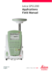
Leica RoadRunner Rail
Technical Reference Manual
Version 3.2
English
Introduction
Purchase
Congratulations on the purchase of a RoadRunner Rail application.
)
To use the product in a permitted manner, please refer to the detailed safety directions in
the User Manual.
Product identification
Symbols
The type and serial number of your product are indicated on the type plate. Enter the type
and serial number in your manual and always refer to this information when you need to
contact your agency or Leica Geosystems authorized service workshop.
Type:
_________________________
Serial No.:
_________________________
The symbols used in this manual have the following meanings:
Type
)
Trademarks
Introduction
•
•
•
All
Description
Important paragraphs which must be adhered to in practice as they enable
the product to be used in a technically correct and efficient manner.
Windows and Windows CE are a registered trademark of Microsoft Corporation
CompactFlash and CF are trademarks of SanDisk Corporation
Bluetooth is a registered trademark of Bluetooth SIG, Inc
other trademarks are the property of their respective owners.
RoadRunner Rail
2
This manual is for
GPS1200 receivers and
TPS1200 instruments
Introduction
GPS1200 receivers
TPS1200 instruments
The following keys refer to GPS1200:
OCUPY (F1), STOP (F1), STORE (F1).
They all have the same functionality in all
manuals which refer to GPS1200 products.
The following keys refer to TPS1200:
ALL (F1), DIST (F2), REC (F3).
They all have the same functionality in all
manuals which refer to TPS1200 products.
OCUPY (F1)
To start measuring the point.
STOP (F1)
To end measuring the point.
STORE (F1)
To record/store the measured point.
ALL (F1)
To measure/record distances and angles.
DIST (F2)
To measure and display distances.
REC (F3)
To record/store the measured data.
RoadRunner Rail
3
Table of Contents
In this manual
Chapter
1
Getting Started with RoadRunner Rail
1.1
1.2
1.3
1.4
1.5
1.6
2
3
Table of Contents
Page
Part
Part
Part
Part
Part
Part
A) Installing all of the necessary Software
B) Importing the Track Design with LEICA Geo Office
C) Loading the Track Design onto the Receiver/Instrument
D) Turning on and Starting the Program
E) RoadRunner Begin
F) RoadRunner Setup
7
7
8
13
14
15
18
Checking a Track with Rail Check
20
2.1
2.2
2.3
2.4
2.5
2.6
2.7
2.8
20
21
22
23
25
27
30
35
Step
Step
Step
Step
Step
Step
Step
Step
1)
1)
2)
3)
3)
4)
5)
6)
Positioning the GPS
Positioning the TPS
Selecting Rail Check
Working in Standard mode
Working in Advanced mode
Checking the Track
Using Offsets
Using the Extras Menu
Setting out a Track with Rail Stake-Out
38
3.1
3.2
3.3
3.4
3.5
3.6
38
39
40
41
43
45
Step
Step
Step
Step
Step
Step
1)
1)
2)
3)
3)
4)
Positioning the GPS
Positioning the TPS
Selecting Rail Stake-Out
Working in Standard mode
Working in Advanced mode
Setting Out the Track
RoadRunner Rail
4
3.7
3.8
3.9
4
5
6
52
55
60
Managing your Projects and Jobs
62
4.1
4.2
4.3
4.4
4.5
4.6
62
66
67
68
69
71
Overview
Selecting a Project by Browsing a List of Projects
Selecting a Project by Resuming the Last Task
Creating a New Project
Editing an Existing Project
Deleting an Existing Project
Managing the Rail Job
72
5.1
5.2
5.3
5.4
72
73
75
81
81
83
89
Overview
Working with the Design Data
Working with the Tasks
Viewing and Editing the Design Data
5.4.1
Overview
5.4.2
Viewing the Design Data
5.4.3
Editing the Design Data
Configuring
6.1
6.2
6.3
Table of Contents
Step 5) Understanding the Stake Pages
Step 6) Using Offsets
Step 7) Using the Extras Menu
91
Overview of all Configuration Settings
Configuration Settings for the Project - Project Config
6.2.1
The General Page
6.2.2
The Posit Page (TPS only)
Configuration Settings for the Program - Rail Config
6.3.1
The General Page
6.3.2
The Rail Page
6.3.3
The Check Page
RoadRunner Rail
91
92
92
95
97
97
101
107
5
6.4
6.3.4
The Info&Plot Page
6.3.5
The Logfile Page
Auto Positioning (TPS only)
6.4.1
Overview (TPS only)
6.4.2
Auto Position 2D + Measure (TPS only)
6.4.3
Auto Position Advanced (TPS only)
7
Using Rail Editor for Superelevation
125
8
Understanding the Terms and Expressions
130
8.1
8.2
8.3
8.4
8.5
8.6
8.7
8.8
130
132
135
137
139
140
143
144
Overview
Working with a Single Track
Working with Multiple Tracks
Rail Check Elements and Rail Stake-Out Elements
Working with Offsets
Working with Horizontal Shifts and Vertical Shifts
Working with Heights
Working with Pendular Displacements
Index
Table of Contents
110
118
119
119
121
123
147
RoadRunner Rail
6
1
Getting Started with RoadRunner Rail
1.1
Part A) Installing all of the necessary Software
Install LEICA Geo Office
•
LGO runs under Windows2000 or WindowsXP and can only be installed successfully if the
user is logged in as the Administrator. To install LGO, run the LAUNCH.EXE from the CD
Rom and follow the instructions on the screen.
Install Design To Field
•
To successfully prepare the track design for use on the receiver/instrument, the data
must first be converted from its original format to an on-board job. This is achieved using
’Design to Field’, a component of LGO which is automatically installed with LGO.
Install Importers
•
The field importers are used by ’Design to Field’ to read in the track design. These
importers are installed separately and have the file extension *.rri.
The latest version of the Design to Field importers may be found in the downloads
section of the Leica Geosystems website:
http://www.leica-geosystems.com/s-e/en/downloads/lgs_page_catalog.htm?cid=3291
•
Install Rail Editor
•
Rail Editor is a PC program for defining the height of the rails relative to the horizontal
and vertical alignments (superelevation). Rail Editor is automatically installed into LGO
from the ’Field Importers’ install package, which may be found in the downloads section
of the Leica Geosystems website. Rail Editor may be run either externally or within
’Design To Field’.
Install RoadRunner and
RoadRunner Rail
•
These are the on-board programs which are loaded onto the receiver/instrument:
• via a CF card (under the System folder), which is inserted into the receiver/instrument,
• via a serial cable and LGO.
Getting Started with RoadRunner Rail
RoadRunner Rail
7
1.2
Part B) Importing the Track Design with LEICA Geo Office
Importing the design
1.
Starting the ’Design to Field’ program.
To import a track centre line select ’Design to Field’
from the Tools menu in LGO.
2.
Selecting an Import Type.
To successfully prepare track design for on-board
use it has to be converted from its original data
format to an on-board job which will run on the
receiver/instrument.
Select Importer Type = ’Rail Data’.
3.
Selecting a Field Importer.
Importers are used to convert the data. Additional
importer formats can be added to the drop-down
list by clicking on ’Manage’.
Select the importer related to the track design from
the drop-down list of available importers.
4.
Getting Started with RoadRunner Rail
RoadRunner Rail
Importing.
Click ’Import’ to start the file selection wizard.
8
5.
Selecting the job type.
Select the appropriate job type.
For single tracks, select ’Rail Design-Single Track’.
For double tracks, select ’Rail Design-Double Track’.
A single track design may consist of a horizontal
alignment, a vertical alignment and superelevation.
A double track design may consist of a horizontal
alignment, a vertical alignment and superelevation
for each track. Alternatively, a third horizontal aligment may also be defined and used for calculating
the chainage of both tracks (chainage centre line).
Click ’Next’ to move to the next page of the wizard.
Getting Started with RoadRunner Rail
RoadRunner Rail
9
6.
Selecting the horiz and vert alignment files.
In the case of a single track, select the horizontal
and vertical alignments using the browse buttons.
In the case of a double track, three panels are used
to define the design data. The arrows at the bottom
of the panel may be used to move between the
different panels.
First Panel: Centre Line
The first panel defines the horizontal and
vertical alignment of the chainage centre line.
Note, it is not mandatory to select a chainage
centre line, if the chainage for each track is to be
calculated relative to each track centre line. Then
the horizontal and vertical alignment on the first
panel may be left blank.
Second Panel: Left Track
The second panel defines the horizontal and
vertical alignments and the rail definition
(superelevation) of the left track.
Third Panel: Right Track
The third panel defines the horizontal and
vertical alignments and the rail definition
(superelevation) of the right track.
Click ’Next’ to move to the next page of the wizard.
Getting Started with RoadRunner Rail
RoadRunner Rail
10
7.
Entering the alignment tolerances.
Enter the appropriate horizontal and vertical tolerances to be used during the checking of the alignments.
Click ’Next’ to move to the next page of the wizard.
8.
Checking the track design.
When the track design has been imported, information is displayed to show the sucesss or failure of
the import.
When the import is successful:
Click ’Next’ to move to the next page of the wizard.
When the import is unsuccessful:
Click ’Back’ to step back through the wizard.
9.
Entering the range of chainages to be used.
Enter the range of chainages to be exported.
Click ’Next’ to move to the next page of the wizard.
Getting Started with RoadRunner Rail
RoadRunner Rail
11
10.
Checking the summary report.
When the report is correct:
Click ’Finish’ to complete the wizard.
When the report is incorrect:
Click ’Back’ to step back through the wizard.
11.
Viewing the track design.
The track design can be viewed graphically.
Click ’Export’ to create the files for on-board use.
12.
Creating the files for on-board use.
The track design can now be prepared.
Click ’OK’ to create the files for on-board use. The
database files are created and are located in the
same folder as the source alignment files.
)
Getting Started with RoadRunner Rail
RoadRunner Rail
Design to Field User Manual.
Refer to the ’Design to Field User Manual’ for details
on importing various types of data with various field
importers. This manual is included in the Design to
Field Converters install application
’RR_Design_to_Field.exe’, which can be downloaded.
12
1.3
Part C) Loading the Track Design onto the Receiver/Instrument
Loading the design
Getting Started with RoadRunner Rail
1.
RoadRunner Rail
Once the track design has been converted, copy all
of the database files to the DBX folder of the
CF Card.
13
1.4
Part D) Turning on and Starting the Program
Starting the program
1.
Turning on the receiver/instrument.
For GPS: Press the ’PROG’ key.
For TPS: Press and hold down the ’PROG’ key for 2 s.
2.
Selecting Programs from the Main Menu.
Select ’Programs’ from the Main Menu, or
Press the ’PROG’ key on the keyboard, or
Press a hot key (F7)-(F12),
(which has been user-configured), or
Press the ’USER’ key,
(which has been user-configured).
3.
Selecting the RoadRunner group of programs.
Select ’RoadRunner’ from the Programs menu.
This program is licence protected. The program is
activated through a specific licence key. This licence
key can be entered either under ’Main Menu:
Tools...\Licence Keys’ or the first time the program
is started.
Press ’CONT (F1)’ to continue to the next screen.
Getting Started with RoadRunner Rail
RoadRunner Rail
14
1.5
Part E) RoadRunner Begin
Positioning the GPS
This screen shows the following:
To select the coordinate system, codelist, configuration set and antenna for the survey.
CONT (F1)
To continue to the next screen.
CONF (F2)
To access the configuration settings.
Refer to "6 Configuring".
RESUM (F4)
To resume the last used and stored task. This is a
recommended feature when using Advanced mode.
CSYS (F6)
To change the current co-ordinate system.
Field
Description of Field
Coord System
Output. The active coordinate system. Use CSYS
(F6) to change the coordinate system.
Rail jobs are defined in local grid coordinates. The
right coordinate system must be chosen for the rail
job.
Codelist
Choicelist. The active codelist. All codelists from
Main Menu: Manage...\Codelists can be selected.
Config Set
Choicelist. The active configuration set. All configuration sets from Main Menu: Manage...\Configuration Sets can be selected.
Getting Started with RoadRunner Rail
RoadRunner Rail
15
Positioning the TPS
Field
Description of Field
Antenna
Choicelist. The antenna currently set in the
selected configuration set. All antennas from Main
Menu: Manage...\Antennas may be selected.
This screen shows the following:
To select the coordinate system, codelist, configuration set and reflector for the survey.
CONT (F1)
To continue to the next screen.
CONF (F2)
To access the configuration settings.
Refer to "6 Configuring".
SETUP (F3)
To set up an instrument station by determining the
station coordinates and orienting the horizontal circle.
RESUM (F4)
To resume the last used and stored task. This is a
recommended feature when using Advanced mode.
CSYS (F6)
To change the current co-ordinate system.
Field
Description of Field
Coord System
Output. The active coordinate system. Use CSYS
(F6) to change the coordinate system.
Rail jobs are defined in local grid coordinates. The
right coordinate system must be chosen for the rail
job.
Getting Started with RoadRunner Rail
RoadRunner Rail
16
Field
Description of Field
Codelist
Choicelist. The active codelist. All codelists from
Main Menu: Manage...\Codelists can be selected.
Config Set
Choicelist. The active configuration set. All configuration sets from Main Menu: Manage...\Configuration Sets can be selected.
Reflector
Choicelist. The reflector currently set in the
selected configuration set. All reflectors from Main
Menu: Manage...\Reflectors may be selected.
Add. Constant
Output. The additive constant stored with the
chosen reflector.
Getting Started with RoadRunner Rail
RoadRunner Rail
17
1.6
Part F) RoadRunner Setup
RoadRunner Setup
This screen shows the following:
An overview of the setup information selected for the survey.
CONT (F1)
To continue to the next screen.
CONF (F2)
To access the configuration settings.
Refer to "6 Configuring" for details.
PROJ (F4)
To edit the currently selected project.
Refer to "4 Managing your Projects and Jobs".
DATA (F5)
To view/edit the data in the rail job.
Refer to "5.4 Viewing and Editing the Design Data".
Field
Description of Field
Application
To select the relevant program. This field lists all of
the programs that have been loaded into the RoadRunner group. Ensure that RR Rail is selected.
Stake/Check
To select either Stake or Check for the survey.
Getting Started with RoadRunner Rail
RoadRunner Rail
18
Field
Description of Field
Method
To select the relevant method for the survey. The
method is set to Track and can not be changed.
Mode
To select either Standard mode or Advanced mode.
Project
To select the relevant project for the survey. Refer
to "4 Managing your Projects and Jobs" for details.
Fixpoint Job
The fixpoint job, as defined by the project.
Meas Job
The measure job, as defined by the project.
Rail job
The rail job, as defined by the project.
DTM (Digital Terrain Model) Job
The DTM job, as defined by the project.
Getting Started with RoadRunner Rail
RoadRunner Rail
19
2
Checking a Track with Rail Check
2.1
Step 1) Positioning the GPS
Positioning the sensor
Once the task has been defined and selected, the
receiver can be set.
Select the necessary coordinate system, codelist,
configuration set and antenna for the survey. All
stake-out methods and check methods share this
common screen.
It is possible to skip this screen.
Refer to "6 Configuring" for configurations.
Refer to "1.5 Part E) RoadRunner Begin" for a
description of the keys and the fields.
Press ’CONT (F1)’ to continue to the next screen.
Checking a Track with Rail Check
RoadRunner Rail
20
2.2
Step 1) Positioning the TPS
Positioning the sensor
Once the task has been defined and selected, the
instrument can be positioned and oriented. This
screen allows the instrument position to be established.
Select the necessary coordinate system, codelist,
configuration set and reflector for the survey. All
stake-out methods and check methods share this
common screen.
It is possible to skip this screen.
Refer to "6 Configuring" for configurations.
Refer to "1.5 Part E) RoadRunner Begin" for a
description of the keys and the fields.
Press ’CONT (F1)’ to continue to the next screen.
Checking a Track with Rail Check
RoadRunner Rail
21
2.3
Step 2) Selecting Rail Check
Selecting Check
1.
Refer to "1 Getting Started with RoadRunner Rail"
for details on starting check surveys.
2.
Select 'Check' and 'Track'.
Press ’CONF (F2)’ to access configuration settings.
Refer to "6 Configuring" for configurations.
Checking a Track with Rail Check
RoadRunner Rail
22
2.4
Step 3) Working in Standard mode
Standard mode
1.
Selecting Mode=Standard.
For standard mode and using the Define Page,
ensure that Mode=Standard is set.
Press ’CONT (F1)’ to continue to the next screen.
2.
Working with the Define Page.
Layers contained in the active rail job can be
selected from this page. These elements, combined
with other settings on the page can easily be
changed during the survey.
CONT (F1)
To continue to the next screen.
SHIFT CONF (F2)
To access the configuration settings.
Refer to "6 Configuring".
Press ’CONT (F1)’ to continue to the next screen.
Field
Description of Field
Layer
Choicelist. To select a layer in the active rail job.
Checking a Track with Rail Check
RoadRunner Rail
23
Field
Description of Field
Ch Stringline
Output. Shows the chainage stringline, at the
selected layer.
Chainage
User Input. To enter a chainage (ranging between
the start chainage and end chainage) of the
chainage centre line. Only those elements which
appear at this chainage can then be selected from
’Select Rail’.
Select Rail
Choicelist. The measured point values may be
compared with the left rail, the right rail or the
track centre line. The ’Select Rail’ choicelist allows
the stringline with which measured values should
be compared, to be selected. The possible options
are:
’Left Rail’, ’Right Rail’ and ’Centre Line’.
Checking a Track with Rail Check
RoadRunner Rail
24
2.5
Step 3) Working in Advanced mode
Advanced mode
1.
Selecting Mode=Advanced.
For advanced mode and using Tasks, ensure that
Mode=Advanced is set.
Press ’CONT (F1)’ to continue to the next screen.
2.
Working with Task management.
In order to check a track, a task needs to be created
or selected. The task defines which track is to be
checked and it also defines any shifts that are to be
used during the check survey.
This screen lists already defined tasks.
Refer to "5.3 Working with the Tasks" for details on
creating/selecting tasks.
CONT (F1)
To continue to the next screen.
NEW (F2)
To create a new task.
EDIT (F3)
To edit the selected task.
Checking a Track with Rail Check
RoadRunner Rail
25
DEL (F4)
To delete the selected task.
MORE (F5)
To toggle between date and time info.
TEMP (F6)
To create a temporary task. This task is identical
to any other task but is not stored for later use.
Press ’CONT (F1)’ to continue to the next screen.
Checking a Track with Rail Check
RoadRunner Rail
26
2.6
Step 4) Checking the Track
The General page
Information regarding the measured point may be
entered in the ’General’ page. This screen allows any
point of the track to be checked against design
values.
Point ID
The point ID of the point about to be recorded.
Antenna Ht
The antenna height.
Reflector Ht
The reflector height.
Select Rail
The measured point values may be compared
with the left rail, the right rail or the track centre
line. The ’Select Rail’ choicelist allows the stringline with which measured values should be
compared, to be selected. The possible options
are:
’Left Rail’, ’Right Rail’ and ’Centre Line’.
Check Offset
Applies a horizontal offset perpendicular to the
stringline used for comparing the measured
point.
Check Ht Diff
Applies a vertical offset to the stringline used for
comparing the measured point.
Checking a Track with Rail Check
RoadRunner Rail
27
)
)
Manual Height
A height which is entered manually by the user.
The value typed in is used instead of design
height or DTM height.
If no value is typed in, the height from design is
used.
Ht LowerRail
Defines the absolute height of the lowest rail at
the defined chainage.
Cant Left
Defines the superelevation at the left rail. If the
superelevation is rotated around the left rail, the
superelevation would be zero.
This field is only active when ’Use Cant=Manual’.
Refer to "6.3 Configuration Settings for the
Program - Rail Config" for details on configuration settings.
Cant Right
Defines the superelevation at the right rail. If the
track is rotated around the right rail, the superelevation would be zero. The total superelevation
(left + right) is applied across the distance
defined as the superelevation base in the configuration.
This field is only active when ’Use Cant=Manual’.
Refer to "6.3 Configuration Settings for the
Program - Rail Config" for details on configuration settings.
Checking a Track with Rail Check
RoadRunner Rail
28
Press ’PAGE (F6)’ to move to the next page.
The Info page
The ’Info’ page displays the differences between
the measured and design data.
The fields viewed in the ’Info’ page may be configured by the user in the ’Info&Plot’ page of the
configuration settings. Configuration settings may
be accessed by pressing SHIFT CONF (F2). Refer to
"6 Configuring" for configurations.
Press ’PAGE (F6)’ to move to the next page.
The Plot page
The ’Plot’ page displays a plot of the measured
point with respect to the track design.
The actual graphical representation shown in the
’Plot’ page may be configured by the user in the
’Info&Plot’ page of the configuration settings.
Configuration settings may be accessed by pressing
SHIFT CONF (F2). Refer to "6 Configuring" configurations.
Press ’PAGE (F6)’ to move to the first page.
Checking a Track with Rail Check
RoadRunner Rail
29
2.7
Step 5) Using Offsets
Overview
It is often the case that it is necessary to set out
points with a fixed plan offset and fixed height
offset from a known reference line (centre line or
rail). In RoadRunner Rail, these offsets may be
entered manually or stored as part of the rail job
and recalled whenever they are required.
Offsets are applied in the same way, irrespective of
how the rail design has been entered and whether
the offsets are manually entered or whether library
offsets are used. The sign of the offsets conforms
to the offset sign convention described in "8.5
Working with Offsets".
b
c
d
a
Rail12_13
a)
b)
c)
d)
Checking a Track with Rail Check
RoadRunner Rail
Reference line (right rail)
Point to stake
Stake Ht. Offset
Stake Offset
30
Using offsets:
enter manual offsets
Checking a Track with Rail Check
1
When the field "Offsets=Manual’ is set in the
configuration settings, then manual offsets may be
entered using the ’Check Offset’ field and the
’Check Ht. Diff’ field. Refer to "6.3 Configuration
Settings for the Program - Rail Config" for details on
configuration settings.
2
Check Offset
The Check Offset is a horizontal offset applied to
the position of the reference line as defined by
the design data or to the position calculated
using manually entered data using the nominal
gauge.
Check Ht Diff
The Check Ht Diff is a vertical offset applied to
the height of the reference line as defined by
the design data or to the position calculated
using manually entered data using the superelevation and superelevation base.
Manual Height
A height which is entered manually by the user.
The value typed in is used instead of design
height or DTM height.
If no value is typed in, the height from design is
used.
RoadRunner Rail
31
Using offsets:
recall library offsets
Checking a Track with Rail Check
1
When the field "Offsets=From Library’ is set in the
configuration settings, the offsets that have been
stored may be used. Refer to "6.3 Configuration
Settings for the Program - Rail Config" for details on
configuration settings.
2
Offsets
The point ID of the stored stake offsets. To
select a different stored offset or to create a
new point, highlight the current point ID in the
’Offsets’ field and open the choicelist. Refer to
"Defining the offsets" for details.
Select Rail
Defines to which reference line the offset has
been defined, three options are available:
Centre Line:
The horizontal alignment.
Left Rail:
The left rail as defined in the design data.
Right Rail:
The right rail as defined in the design data.
RoadRunner Rail
32
Check Offset
The Check Offset is a horizontal offset applied to
the position of the reference line as defined by
the design data or to the position calculated
using manually entered data using the nominal
gauge.
Check Ht Diff
The Check Ht Diff is a vertical offset applied to
the height of the reference line as defined by
the design data or to the position calculated
using manually entered data using the superelevation and superelevation base.
Manual Height
A height which is entered manually by the user.
The value typed in is used instead of design
height or DTM height.
If no value is typed in, the height from design is
used.
Defining the offsets
Checking a Track with Rail Check
1
RoadRunner Rail
To select a different stored offset or to create a
new point, highlight the current point ID in the
’Offsets’ field and open the choicelist.
33
2
This screen allows offsets relative to a reference
line to be defined and stored in the rail job. These
points may be recalled at any time.
CONT (F1)
To select the point and to continue.
ADD (F2)
To enter a new point.
EDIT (F3)
To edit an existing point.
DEL (F4)
To delete an existing point.
MORE (F5)
To display additional point information.
Press ’ADD (F2)’ to enter a new point.
3
This screen allows the values of the check offsets to
be entered/edited. In addition to the horizontal and
vertical offsets, a point ID may be entered for each
point.
CONT (F1)
To record the point and to continue.
Checking a Track with Rail Check
RoadRunner Rail
34
2.8
Step 6) Using the Extras Menu
Overview
Accessing Extras Menu
Checking a Track with Rail Check
Additional functions for checking the track may be
accessed through the Extras menu. This functionality is additional to those already existing functions
which are available via the function keys. The Extras
menu is accessed from every check screen.
1.
Press ’SHIFT EXTRA (F5)’ to access the Extras menu.
2.
DTM Height
Allows switching to a height which is retrieved
from an existing Height Layer, as defined in the
DTM job.
2nd point of Cant
To determine the actual cant of two rails.
RoadRunner Rail
35
Extras:
DTM Height
By selecting a Height Layer, the heights can be
obtained from the layers of the DTM Job.
Selecting <None> means, no DTM heights are
applied for stake out or check.
This option is only active when a DTM Job has been
assigned to the project. Refer to "4 Managing your
Projects and Jobs" for details on assigning jobs to
projects.
Extras:
Second point of Cant
In order to calculate the current cant, it is necessary
to measure two points, one on each rail. A mechanical device may be used to measure these points if
required.
Additionally, the current cant can be calculated by
firstly measuring any two points (example, the track
centre line and lower rail) and secondly by using the
superelevation base. The calculation is dependent
upon the superelevation base.
Checking a Track with Rail Check
RoadRunner Rail
36
d
e
c
b
a
Rail12_15
a)
b)
c)
d)
e)
left rail
right rail
first point
second point of cant
current cant
Measuring the first point
The first point may be measured directly from
the Check Track panel.
Measuring the second point
The second point should be measured after
accessing the 2nd Point of Cant function in the
Extras menu. Once the second point has been
measured, the value Current Cant will be
displayed on the ’Info’ page.
Checking a Track with Rail Check
RoadRunner Rail
37
3
Setting out a Track with Rail Stake-Out
3.1
Step 1) Positioning the GPS
Positioning the sensor
Once the task has been defined and selected, the
receiver can be set.
Select the necessary coordinate system, codelist,
configuration set and antenna for the survey. All
stake-out methods and check methods share this
common screen.
It is possible to skip this screen.
Refer to "6 Configuring" for configurations.
Refer to "1.5 Part E) RoadRunner Begin" for a
description of the keys and the fields.
Press ’CONT (F1)’ to continue to the next screen.
Setting out a Track with Rail Stake-Out
RoadRunner Rail
38
3.2
Step 1) Positioning the TPS
Positioning the sensor
Once the task has been defined and selected, the
instrument can be positioned and oriented. This
screen allows the instrument position to be established.
Select the necessary coordinate system, codelist,
configuration set and reflector for the survey. All
stake-out methods and check methods share this
common screen.
It is possible to skip this screen.
Refer to "6 Configuring" for configurations.
Refer to "1.5 Part E) RoadRunner Begin" for a
description of the keys and the fields.
Press ’CONT (F1)’ to continue to the next screen.
Setting out a Track with Rail Stake-Out
RoadRunner Rail
39
3.3
Step 2) Selecting Rail Stake-Out
Selecting Stake-Out
1.
Refer to "1 Getting Started with RoadRunner Rail"
for details on starting setting out surveys.
2.
Select 'Stake' and 'Track'.
Press ’CONF (F2)’ to access configuration settings.
Refer to "6 Configuring" for configurations.
Setting out a Track with Rail Stake-Out
RoadRunner Rail
40
3.4
Step 3) Working in Standard mode
Standard mode
1.
Selecting Mode=Standard.
For standard mode and using the Define Page,
ensure that Mode=Standard is set.
Press ’CONT (F1)’ to continue to the next screen.
2.
Setting the Define Page.
Layers and stringlines contained in the active rail job
can be selected from this page. These elements,
combined with other settings on the page can easily
be changed during the survey.
CONT (F1)
To continue to the next screen.
SHIFT CONF (F2)
To access the configuration settings.
Refer to "6 Configuring".
Press ’CONT (F1)’ to continue to the next screen.
Field
Description of Field
Layer
Choicelist. To select a layer in the active rail job.
Setting out a Track with Rail Stake-Out
RoadRunner Rail
41
Field
Description of Field
Ch Stringline
Output. Shows the chainage stringline, at the
selected layer.
Chainage
User Input. To enter a chainage (ranging between
the start chainage and end chainage) of the
chainage centre line. Only those elements which
appear at this chainage can then be selected from
’Select Rail’.
Select Rail
Choicelist. The staked point values may be
compared with the left rail, the right rail or the
track centre line. The ’Select Rail’ choicelist allows
the stringline with which staked values should be
compared, to be selected. The possible options
are:
’Left Rail’, ’Right Rail’ and ’Centre Line’.
Setting out a Track with Rail Stake-Out
RoadRunner Rail
42
3.5
Step 3) Working in Advanced mode
Advanced mode
1.
Selecting Mode=Advanced.
For advanced mode and using Tasks, ensure that
Mode=Advanced is set.
Press ’CONT (F1)’ to continue to the next screen.
2.
Task management.
In order to stake a track, a task needs to be created
or selected. The task defines which track is to be
staked and also defines any shifts that are to be
used during the setting out survey.
This screen lists already defined tasks.
Refer to "5.3 Working with the Tasks" for details on
creating/selecting tasks.
CONT (F1)
To continue to the next screen.
NEW (F2)
To create a new task.
EDIT (F3)
To edit the selected task.
Setting out a Track with Rail Stake-Out
RoadRunner Rail
43
DEL (F4)
To delete the selected task.
MORE (F5)
To toggle between date and time info.
TEMP (F6)
To create a temporary task. This task is identical
to any other task but is not stored for later use.
Press ’CONT (F1)’ to continue to the next screen.
Setting out a Track with Rail Stake-Out
RoadRunner Rail
44
3.6
Step 4) Setting Out the Track
Overview
It is possible to set out points using a rail job with
and without a stored rail design.
When the position of the rails is not stored in the rail
job, it is possible to set-out:
• The horizontal and vertical alignments
• Points with a known horizontal and vertical
offset from the horizontal and vertical alignments
• The rails of the track by entering the track
superelevation, superelevation base and nominal
gauge
• Points with know horizontal and vertical offsets
from the manually defined rails.
When the position of the rails is stored in the rail
job, it is possible to set-out:
• The horizontal and vertical alignments
• Points with a known horizontal and vertical
offset from the horizontal and vertical alignments
• The rails of the track
• Points with know horizontal and vertical offsets
from the defined rails.
Setting out a Track with Rail Stake-Out
RoadRunner Rail
45
Defining
the point to set out
When setting out the track, a number of fields that
may be entered in the ’General’ page are identical
whether or not the rail design is stored in the rail
job.
Point ID
The point ID of the point that will be set out.
Antenna Ht
The antenna height.
Reflector Ht
The reflector height.
Def Chainage
The defined chainage of the point to be set out.
In the case of multiple tracks that have a defined
chainage centre line, the chainage to be set out
always refers to the chainage of the chainage
centre line and not to the chainage of the track
centre line.
Ch Increment
If a point is to be staked at more than one
chainage, a chainage increment may be defined.
Use of the remaining parameters on the General
panel changes slightly depending on whether a
vertical alignment is available and whether the
rail data has been stored within the job.
Setting out a Track with Rail Stake-Out
RoadRunner Rail
46
Stake Offset
The Stake Offset is a horizontal offset applied to
the position of the reference line as defined by
the design data or to the position calculated
using manually entered data using the nominal
gauge.
Stake Ht Diff
The Stake Ht Diff is a vertical offset applied to
the height of the reference line as defined by
the design data or to the position calculated
using manually entered data using the superelevation and superelevation base.
Manual Height
A height which is entered manually by the user.
The value typed in is used instead of design
height or DTM height.
If no value is typed in, the height from design is
used.
Working with
a horizontal alignment
If the only defined data available is the horizontal
alignment, the position and height of the rail data
may be defined as follows.
Select Rail
Defines which reference line should be staked.
Three options are available:
Centre Line:
The horizontal alignment.
Setting out a Track with Rail Stake-Out
RoadRunner Rail
47
)
Left Rail:
The position of the left rail is calculated using
the nominal gauge entered in the program
configuration. The height of the rail is calculated
using the value of the Ht LowerRail parameter
and the left / right superelevation.
Right Rail:
The position of the right rail is calculated using
the nominal gauge entered in the program
configuration. The height of the rail is calculated
using the value of the Ht LowerRail parameter
and the left / right superelevation.
Ht LowerRail
Defines the absolute height of the lowest rail at
the defined chainage.
Cant Left
Defines the superelevation at the left rail. If the
track is rotated around the left rail, the superelevation would be zero.
This field is only active when ’Use Cant=Manual’.
Refer to "6.3 Configuration Settings for the
Program - Rail Config" for details on configuration settings.
Setting out a Track with Rail Stake-Out
RoadRunner Rail
48
)
Cant Right
Defines the superelevation at the right rail. If the
track is rotated around the right rail, the superelevation would be zero. The total superelevation
(left + right) is applied across the distance
defined as the superelevation base in the configuration.
This field is only active when ’Use Cant=Manual’.
Refer to "6.3 Configuration Settings for the
Program - Rail Config" for details on configuration settings.
Working with
a horizontal and a
vertical alignment
If the available defined data is the horizontal and
vertical alignment, the position and height of the
rail data may be defined as follows.
Select Rail
Defines which reference line should be staked.
Three options are available:
Centre Line:
The horizontal alignment.
Setting out a Track with Rail Stake-Out
RoadRunner Rail
49
)
Left Rail:
The position of the left rail is calculated using
the nominal gauge entered in the program
configuration. The height of the rail is calculated
using the height of the vertical alignment at the
defined chainage and the left / right superelevation.
Right Rail:
The position of the right rail is calculated using
the nominal gauge entered in the program
configuration. The height of the rail is calculated
using the height of the vertical alignment at the
defined chainage and the left / right superelevation.
Cant Left
Defines the superelevation at the left rail. If the
track is rotated around the left rail, the vertical
alignment would coincide with the left rail and
the superelevation would thus be zero.
This field is only active when ’Use Cant=Manual’.
Refer to "6.3 Configuration Settings for the
Program - Rail Config" for details on configuration settings.
Setting out a Track with Rail Stake-Out
RoadRunner Rail
50
)
Cant Right
Defines the superelevation at the right rail. If the
track is rotated around the right rail, the vertical
alignment would coincide with the right rail and
the superelevation would thus be zero. The total
superelevation (left + right) is applied across the
distance defined as the superelevation base in
the configuration.
This field is only active when ’Use Cant=Manual’.
Refer to "6.3 Configuration Settings for the
Program - Rail Config" for details on configuration settings.
Working with
a horizontal and a
vertical alignment and
a stored rail design
If the position and height of the rail data is available
in the rail job, the seting out data may be defined
as follows.
Select Rail:
Defines which reference line should be staked.
Three options are available:
Centre Line:
The horizontal alignment.
Left Rail:
The left rail as defined in the design data or as
defined manually.
Right Rail:
The right rail as defined in the design data or as
defined manually.
Setting out a Track with Rail Stake-Out
RoadRunner Rail
51
3.7
Step 5) Understanding the Stake Pages
The General page
Once the point to set out has been defined, the
sensor may be positioned manually and the
ALL (F1), DIST (F2) and REC (F3) keys may be used
to measure a point. Alternatively, press ’POSIT
SHIFT (F5)’ key to move the instrument to point at
the stake out position. The differences between the
measured point and the defined point may be
viewed in the ’Stake’, ’Info’ and ’Plot’ pages.
Press ’PAGE (F6)’ to move to the next page.
The Stake page
During setting out the differences between the
measured point and the defined point may be seen
in the ’Stake’ page.
The layout of this page may appear with or without
graphics depending upon the values set in the
configuration settings.
Refer to "6 Configuring" for configurations.
The position of the point to stake will be reached
when all difference values are close to zero.
Setting out a Track with Rail Stake-Out
RoadRunner Rail
52
The chainage can be de-/incremented by pressing
left/right arrow key. The defined value for chainage
increment is applied.
Press ’PAGE (F6)’ to move to the next page.
The Info page
The ’Info’ page displays a series of values related to
the setting out of the design point as required by
the user.
The fields viewed in the ’Info’ page may be configured by the user in the ’Info&Plot’ page of the
configuration settings. Configuration settings may
be accessed by pressing SHIFT CONF (F2). Refer to
"6 Configuring" for configurations.
Press ’PAGE (F6)’ to move to the next page.
Setting out a Track with Rail Stake-Out
RoadRunner Rail
53
The Plot page
The ’Plot’ page displays a plot of the measured
point with respect to the track design.
The actual graphical representation shown in the
’Plot’ page may be configured by the user in the
’Info&Plot’ page of the configuration settings.
Configuration settings may be accessed by pressing
SHIFT CONF (F2). Refer to "6 Configuring" configurations.
Press ’PAGE (F6)’ to move to the first page.
Setting out a Track with Rail Stake-Out
RoadRunner Rail
54
3.8
Step 6) Using Offsets
Overview
It is often the case that it is necessary to set out
points with a fixed plan offset and fixed height
offset from a known reference line (centre line or
rail). In RoadRunner Rail, these offsets may be
entered manually or stored as part of the rail job
and recalled whenever they are required.
Offsets are applied in the same way, irrespective of
how the rail design has been entered and whether
the offsets are manually entered or whether library
offsets are used. The sign of the offsets conforms
to the offset sign convention described in "8.5
Working with Offsets".
b
c
d
a
Rail12_13
a)
b)
c)
d)
Setting out a Track with Rail Stake-Out
RoadRunner Rail
Reference line (right rail)
Point to stake
Stake Ht. Offset
Stake Offset
55
Using offsets:
enter manual offsets
Setting out a Track with Rail Stake-Out
1.
When the field "Offsets=Manual’ is set in the
configuration settings, then manual offsets may be
entered using the ’Stake Offset’ field and the
’Stake Ht. Diff’ field. Refer to "6.3 Configuration
Settings for the Program - Rail Config" for details on
configuration settings.
2.
Stake Offset
The Stake Offset is a horizontal offset applied to
the position of the reference line as defined by
the design data or to the position calculated
using manually entered data using the nominal
gauge.
Stake Ht Diff
The Stake Ht Diff is a vertical offset applied to
the height of the reference line as defined by
the design data or to the position calculated
using manually entered data using the superelevation and superelevation base.
RoadRunner Rail
56
Using offsets:
recall library offsets
Setting out a Track with Rail Stake-Out
1.
When the field "Offsets=From Library’ is set in the
configuration settings, the offsets that have been
stored may be used. Refer to "6.3 Configuration
Settings for the Program - Rail Config" for details on
configuration settings.
2.
Offsets
The point ID of the stored stake offsets. To
select a different stored offset or to create a
new point, highlight the current point ID in the
’Offsets’ field and open the choicelist. Refer to
"Defining the offsets" for details.
Select Rail
Defines to which reference line the offset has
been defined, three options are available:
Centre Line:
The horizontal alignment.
Left Rail:
The left rail as defined in the design data.
Right Rail:
The right rail as defined in the design data.
RoadRunner Rail
57
Stake Offset
The Stake Offset is a horizontal offset applied to
the position of the reference line as defined by
the design data or to the position calculated
using manually entered data using the nominal
gauge.
Stake Ht Diff
The Stake Ht Diff is a vertical offset applied to
the height of the reference line as defined by
the design data or to the position calculated
using manually entered data using the superelevation and superelevation base.
Defining the offsets
Setting out a Track with Rail Stake-Out
1.
RoadRunner Rail
To select a different stored offset or to create a
new point, highlight the current point ID in the
’Offsets’ field and open the choicelist.
58
2.
This screen allows offsets relative to a reference
line to be defined and stored in the rail job. These
points may be recalled at any time.
CONT (F1)
To select the point and to continue.
ADD (F2)
To enter a new point.
EDIT (F3)
To edit an existing point.
DEL (F4)
To delete an existing point.
MORE (F5)
To display additional point information.
Press ’ADD (F2)’ to enter a new point.
3.
This screen allows the values of the stake offsets to
be entered/edited. In addition to the horizontal and
vertical offsets, a point ID may be entered for each
point.
CONT (F1)
To record the point and to continue.
Setting out a Track with Rail Stake-Out
RoadRunner Rail
59
3.9
Step 7) Using the Extras Menu
Overview
Accessing Extras Menu
Setting out a Track with Rail Stake-Out
Additional functions for setting out the track may
be accessed through the Extras menu. This functionality is additional to those already existing functions which are available via the function keys. The
Extras menu is accessed from every stake screen.
1.
Press ’SHIFT EXTRA (F5)’ to access the Extras menu.
2.
DTM Height
Allows switching to a height which is retrieved
from an existing Height Layer, as defined in the
DTM job.
ΔChainage=0
This sets the defined chainage to the current
measured chainage.
RoadRunner Rail
60
Decrement Chainage
This decreases the defined chainage used for
the stakeout by the amount defined in the increment chainage parameter.
The chainage can be de-/incremented on the
Stake page by pressing left/right arrow key. The
defined value for chainage increment is applied.
Individual Point D
This allows a 2D or 3D point for staking out to be
selected from the fixed point job.
Extras:
DTM Height
Setting out a Track with Rail Stake-Out
By selecting a Height Layer, the heights from the
DTM Job are used as a height reference for staking
out or checking.
The DTM used as Info layer will not be considered
for the stake values.
This option is only active when a DTM Job has been
assigned to the project. Refer to "4 Managing your
Projects and Jobs" for details on assigning jobs to
projects.
RoadRunner Rail
61
4
Managing your Projects and Jobs
4.1
Overview
Overview
Working on a railway construction site implies
working with various data such as:
• Control points
• Horizontal and vertical alignments
• Measurement data
• Rail design
• Digital Terrain Models (DTM)
To avoid having to select individual data sets each
time the program is used, data can be grouped into
projects. This makes the selection much easier and
reduces the risk of selecting a wrong data set.
The job options are:
1. fixpoint job
2. measurement job
3. tunnel job
4. rail job
5. digital terrain Job (DTM)
Managing your Projects and Jobs
RoadRunner Rail
62
Screen
Description
Project A
Rail-Job A
Meas-Job A
Project B
Data-Job A
Road-Job M
Meas-Job B
Rail12_12
Project
A project consists of different kinds of jobs that
are grouped together to form a project. By
selecting a project all referenced jobs are selected
automatically as well.
A
•
•
•
•
•
project can reference:
one data job
one measurement job
one road job
one rail job
one DTM job.
Since jobs are only referenced by a project, they
may be used in more than one RoadRunner
project, as well as in other programs. For example
the same collection of control points may be used
in two different projects.
Managing your Projects and Jobs
RoadRunner Rail
63
Screen
Description
Project A and Project B reference the same data
job (Data-Job A) and road job (Road-Job M),
however, their results are stored into different
measurement jobs (Meas-Job A; Meas-Job B). In
addition, Project A references the rail design data
through a Rail Job (Rail Job A).
Fixpoint Job
The Data Job holds all control point information
needed in the field. For example, control points,
points with known coordinates used for a TPS setup.
Meas Job
The measurement job is where information generated in the field is recorded. All measurements,
points and other values stored in the field are
added to this job.
Road Job
All design information for road data, either typed
in manually or exported from a design package is
stored in the road job. Data stored in this job could
include, for example, information related to the
construction of cuttings and embankments. Like
the data job, it is a source of information. Refer to
the RoadRunner Technical Reference Manual,
chapter 6 "Road Job" for details on road jobs.
Managing your Projects and Jobs
RoadRunner Rail
64
Screen
Description
Tunnel Job
Contains information relating to the design of a
tunnel. The centre line of the tunnel and the tunnel
design profiles are stored in the tunnel job. As with
a road job, the tunnel job is a read-only source of
information. Refer to the RoadRunner Tunnel
Technical Reference Manual for details.
Rail Job
Contains information relating to the design of the
tracks. The centre line(s) of the track and the rails
are stored in the rail job. As with a road job, the rail
job is a read-only source of information.
Refer to "5 Managing the Rail Job"for details.
Digital Terrain Model Job
)
)
Managing your Projects and Jobs
Holds DTM (Digital Terrain Model) data or TIN
(Triangular Irregular Network) data. Like a data job
or road job, the DTM job is a source of information.
Refer to the RoadRunner Technical Reference
Manual for details.
The same job can be used as a data and measurement job.
Since Road jobs, Tunnel jobs, Rail jobs and DTM
jobs are read only, they cannot be selected as a
data or a measurement job. When selecting a job,
a filter is applied to show only the valid jobs in the
selection list.
RoadRunner Rail
65
4.2
Selecting a Project by Browsing a List of Projects
Browsing from a list of
existing projects
A list of all available projects in the internal memory
or on the CompactFlash card are available via the
project browser.
CONT (F1)
To select the highlighted project and continue.
NEW (F2)
To create a new project.
EDIT (F3)
To edit the highlighted project. This project also
becomes the active project.
DEL (F4)
To delete the highlighted project.
MORE (F5)
Toggle between Date and Time info
CFCRD (F6) or INTL (F6)
To switch between the CompactFlash card and
internal memory as the active device.
Managing your Projects and Jobs
RoadRunner Rail
66
4.3
Selecting a Project by Resuming the Last Task
Resuming the last task
RoadRunner retains the last active task used on any
project. When the program is resumed, the last
active task may be accessed again using the
RESUM (F4) key. This avoids the selection of project
and task to be staked out or checked every time the
program is started.
RESUM (F4)
To resume the last task running of the highlighted project. The project to which the task
belongs to is selected automatically.
Managing your Projects and Jobs
RoadRunner Rail
67
4.4
Creating a New Project
Creating a project
1.
Press ’NEW (F2)’ to move to the next screen.
2.
New Project, General page
Enter a ’Name’ (this field is compulsory).
Enter a ’Description’.
Enter a ’Creator’.
Enter a ’Device’ for the project.
Press ’PAGE (F6)’ to move to the next page.
3.
New Project, Jobs page
Select the ’Fixpoint Job’.
Select the ’Meas Job’.
Select the ’Rail Job’
Select the ’DTM Job’.
It is possible to add or remove jobs at a later stage.
Press ’STORE (F1)’ to accept the changes and select
the newly created project as the new active project.
Managing your Projects and Jobs
RoadRunner Rail
68
4.5
Editing an Existing Project
Editing a project
1.
Select the Project line and press ENTER to open the
projects panel.
2.
Press ’EDIT (F3)’ to move to the next screen.
3.
Edit Project, General page
Enter a ’Name’ (this field is compulsory).
Enter a ’Description’.
Enter a ’Creator’.
Enter a ’Device’ for the project.
Press ’PAGE (F6)’ to move to the next page.
Managing your Projects and Jobs
RoadRunner Rail
69
4.
Edit Project, Jobs page
Select the ’Fixpoint Job’.
Select the ’Meas Job’.
Select the ’Rail Job’
Select the ’DTM Job’.
It is possible to add or remove jobs at a later stage.
Press ’STORE (F1)’ to accept the changes and select
the newly created project as the new active project.
Managing your Projects and Jobs
RoadRunner Rail
70
4.6
Deleting an Existing Project
Deleting a project
1.
Select the Project line and press ENTER to open the
projects panel. Deleting a project will not delete the
fixpoint job, measurement job, road job, tunnel job,
rail job or DTM job that it references.
If two projects use the same control points by referencing the same fixpoint job, deleting one project
will not delete the control points for the other
project.
Managing your Projects and Jobs
2.
Highlight the project to delete.
Press ’DEL (F4)’ to delete the project.
3.
Press ’YES (F6)’ to confirm the deletion.
RoadRunner Rail
71
5
Managing the Rail Job
5.1
Overview
Overview
Managing the Rail Job
Each rail job consists of two major parts:
Part 1: Design data:
Contains all the information about the rail design
including the geometry of the centre line and the
rail definition (superelevation).
Part 2: Working tasks:
Tasks define how the design elements of the
track are staked out or checked in the field.
Tasks also define any offsets that should be
applied to the design data.
RoadRunner Rail
72
5.2
Working with the Design Data
Horizontal alignments
and vertical alignments
All rail jobs must consist of at least one horizontal
alignment. Each horizontal alignment may be typed
in manually using the System 1200 Alignment
Toolkit program or converted from a rail design
package using the ’Design To Field’ component
within the Leica Geo Office program.
Horizontal alignments may consist of straights,
circular curves, clothoides, parabolic curves and
bloss curves.
Vertical alignments may consist of straights, circular
curves and parabolic curves.
If a design comprises of multiple tracks, one horizontal alignment may be defined as the chainage
centre line from which all chainages will be calculated and additional horizontal and vertical alignments may be used to define each track.
Managing the Rail Job
RoadRunner Rail
73
Rail definition
Rails may be defined by entering the design data
manually in the field, by using the System1200
Alignment Toolkit program, by using the Rail Editor
PC program or by converting data from a rail design
package using the ’Design To Field’ component
within the LEICA Geo Office program.
Rails are stored as stringlines (continous 2D or 3D
lines) within the rail job.
Tracks
Tracks are used to group related stringlines (centre
line and rails) together.
In the case of a single track, the track centre line
and the two rails are grouped together in one track.
In the case of multiple tracks where one chainage
centre line is used for all tracks, each track consists
of four stringlines: the track centre line, the
chainage centre line and the left and right rails.
In the case of multiple tracks where chainage is
calculated relative to the track centre line, each
track is stored as a single track as described previously.
Managing the Rail Job
RoadRunner Rail
74
5.3
Creating a task
Working with the Tasks
1.
When staking out or checking a track, it is often the
case that it is not possible to finish a particular task
in one go. Rail allows the possibility of storing the
element to be staked out or checked together with
all defined settings as a working task. Tasks are
stored as a part of the project.
A task defines the offsets required for setting out
and checking as well as the track to use and the
chainage limits within which the task applies.
When starting the Rail program, the seven last used
tasks of the selected project are shown.
CONT (F1)
To continue to the next screen.
NEW (F2)
To create a new task.
EDIT (F3)
To edit the selected task.
DEL (F4)
To delete the selected task.
MORE (F5)
To toggle between date and time info.
Managing the Rail Job
RoadRunner Rail
75
TEMP (F6)
To create a temporary task. This task is identical
to any other task but is not stored for later use.
Press ’CONT (F1)’ to continue to the next screen.
2.
The Selection Wizard-Start page defines the name
of the task and whether shifts should be applied to
the design data.
Shifts are applied temporarily to the design data for
the defined task, the original design data is not
modified when a shift is applied. Refer to "8.6
Working with Horizontal Shifts and Vertical Shifts"
for details on shifts.
The same selection wizard is used for all tasks
within the program.
Press ’NEXT (F1)’ to move to the next page.
3.
The second page of the selection wizard defines the
track or centre line to be used for the task.
Press ’NEXT (F1)’ to move to the next page.
Managing the Rail Job
RoadRunner Rail
76
4.
The next page of the wizard displays the horizontal
alignment or a cross-section plot of the rails based
on the selection in the previous screen. This page is
purely informative.
Press ’NEXT (F1)’ to move to the next page.
5.
This page of the selection wizard defines whether
the task should only be applied to a limited section
of the alignment. If the defined chainage range is
exceeded during stake out/check a warning
appears.
FINSH (F1)
To complete the selection wizard.
DEFLT (F5)
To set the chainage limits to the maximum and
minimum chainages available in the rail job.
BACK (F6)
To move back to the previous page of the
wizard.
Managing the Rail Job
RoadRunner Rail
77
Browsing from a list of
existing working tasks
A list of all tasks in the internal memory or on the
CompactFlash card are available via the tasks
browser. The tasks browser may be opened from
any point in the program where a task may be
selected.
CONT (F1)
To select the highlighted task and continue.
NEW (F2)
To create a new task.
EDIT (F3)
To edit the highlighted task.
DEL (F4)
To delete the highlighted task.
MORE (F5)
To display additional task information.
TEMP (F6)
To create a temporary task. This task is identical
to any other task but is not stored for later use.
Managing the Rail Job
RoadRunner Rail
78
Working with shifts
If a shift is defined on the first page of the selection
wizard, the parameters associated with the shift
must be entered after defining the chainage limits.
The application of the shift is dependent upon to
which entity it should be applied: Horizontal alignment or, Vertical alignment. Refer to "8.6 Working
with Horizontal Shifts and Vertical Shifts" for details
on shifts.
The parameters required for applying the shift are
identical for all entities.
For constant shifts:
Beg Chainage:
Chainage from which the shift should be applied.
Beg Shift:
Magnitude of the shift to apply.
End Chainage:
Chainage at which the shift should end.
Managing the Rail Job
RoadRunner Rail
79
For linear shifts:
Beg Chainage:
Chainage from which the shift should be applied.
Beg Shift:
Magnitude of the shift to apply (start chainage).
End Chainage:
Chainage at which the shift should end.
End Shift:
Magnitude of the shift to apply (end chainage).
Managing the Rail Job
RoadRunner Rail
80
5.4
Viewing and Editing the Design Data
5.4.1
Overview
Viewing and Editing
The design data stored within the rail job contains all of the information about the rail
design. This includes the stringlines and layers. The design data can be viewed and partially
edited in these View and Edit screens.
CONT (F1)
To return to the RoadRunner Rail Setup screen.
EDIT (F3)
To edit the following design data:
1) to edit the general job details,
2) to change the start chainage of the centre line
of the selected layer.
VIEW (F4)
To view the following design data in a selected
layer:
1) to view specific details of the layer centre line,
2) to view cross-section plots.
Managing the Rail Job
RoadRunner Rail
81
Field
Description of field
Job Name
The name of the active rail job, as defined in the project.
Layer
To select a layer from the active rail job. All of the layers within the
active rail job can be selected.
#Stringlines
The number of stringlines from the selected layer.
Centre line
The name of the layer centre line.
Chainage
To enter a start chainage to use when viewing the data. The default
value is the start chainage of the layer centre line.
Ch Increment
To enter a chainage increment to use when stepping through the data
)
Managing the Rail Job
If a centre line has not been defined, a start chainage cannot be entered and the
field will be shown as "----". If a centre line has not been defined, a chainage increment cannot be entered and the field will be shown as "----".
RoadRunner Rail
82
5.4.2
Viewing the Design Data
Viewing details of the
layer centre line
This page shows the following:
Geometrical details of the selected stringline at the selected chainage.
CONT (F1)
To return to the View&Edit Data screen.
CH+ (F2)
To increase the chainage by the chainage increment, as defined in the View&Edit Data screen.
CH- (F3)
To decrease the chainage by the chainage increment, as defined in the View&Edit Data screen.
SEG (F4)
To enter the Segment Info screen.
HZ/VT (F5)
To toggle between the vertical alignment data and
the horizontal alignment data.
PAGE (F6)
To move to the next page.
Field
Description of field
Line name
To select a stringline from the layer.
Easting
The East coordinate of the stringline.
Northing
The North coordinate of the stringline.
Height
The height of the stringline.
The following fields/values can be toggled, by using the HZ/VT (F5) softkey:
Managing the Rail Job
Hz Tangent/Grade
The tangent direction or grade of the stringline.
Hz/Vt Radius
The horizontal/vertical radius of the stringline segment.
RoadRunner Rail
83
Field
Description of field
Hz/Vt Type
The horizontal/vertical segment type.
Hz/Vt Offset
The horizontal/vertical offset to the layer centre line.
)
Viewing a list of all
stringlines in the layer
If a value has not been defined, the field will be shown as "----".
This page shows the following:
A list of all stringlines in the current layer, their centre line offsets and height differences or
absolute heights at the selected chainage.
CONT (F1)
To return to the View&Edit Data screen.
CH+ (F2)
To increase the chainage by the chainage increment, as defined in the View&Edit Data screen.
CH- (F3)
To decrease the chainage by the chainage increment, as defined in the View&Edit Data screen.
SEG (F4)
To enter the Segment Info screen.
MORE (F5)
To toggle between the height differences or absolute heights at the selected chainage.
PAGE (F6)
To move to the next page.
SHIFT HOME (F2)
To move to the start of the list of stringlines.
SHIFT END (F3)
To move to the end of the list of stringlines.
Managing the Rail Job
RoadRunner Rail
84
Column
Description of column
Line Name
The name of the stringline in the selected layer.
CL off
The offset of the stringline from the layer centre line.
The following columns/values can be toggled, by using the MORE (F5) softkey:
Managing the Rail Job
Ht Diff
The height difference of the stringline to the layer centre line.
Height
The absolute height of the stringline.
RoadRunner Rail
85
Viewing cross sections
This page shows the following:
A cross section view of the design data at the selected chainage. No selection or zoom/pan
functionality is available.
CONT (F1)
To return to the View&Edit Data screen.
CH+ (F2)
To increase the chainage by the chainage increment, as defined in the View&Edit Data screen.
CH- (F3)
To decrease the chainage by the chainage increment, as defined in the View&Edit Data screen.
SEG (F4)
To enter the Segment Info screen.
PAGE (F6)
To move to the next page.
Managing the Rail Job
RoadRunner Rail
86
Viewing the segment:
the Hz Alignment page
This page shows the following:
Detailed horizonal alignment information about the current stringline segment.
CONT (F1)
To return to the View screens.
SEG+ (F2)
To move to the next segment.
SEG- (F3)
To move to the previous segment.
ENDP/STRTP (F4)
To toggle between the start point and the end
point of the segment.
PAGE (F6)
To move to the next page.
Field
Description of field
Line Name
The name of the selected stringline.
The following fields/values can be toggled, by using the ENDP/STRTP (F4) softkey:
Chainage
The chainage of start/end point of the segment.
Easting
The East coordinate of the start/end point of the segment.
Northing
The North coordinate of the start/end point of the segment.
Height
The height of the start/end point of the segment.
Hz Tangent
The tangent direction at the start/end point of the segment.
Hz Radius
The radius at the start/end point of the segment.
Hz Type
The current segment type.
)
Managing the Rail Job
If a value has not been defined, the field will be shown as "----".
RoadRunner Rail
87
Viewing the segment:
the Vt Alignment page
This page shows the following:
Detailed vertical alignment information about the current stringline segment.
CONT (F1)
To return to the View screens.
SEG+ (F2)
To move to the next segment.
SEG- (F3)
To move to the previous segment.
ENDP/STRTP (F4)
To toggle between the start point and the end
point of the segment.
PAGE (F6)
To move to the next page.
Field
Description of field
Line Name
The name of the selected stringline.
The following fields/values can be toggled, by using the ENDP/STRTP (F4) softkey:
Chainage
The chainage of start/end point of the segment.
Easting
The East coordinate of the start/end point of the segment.
Northing
The North coordinate of the start/end point of the segment.
Height
The height of the start/end point of the segment.
Grade
The grade at the start/end poin of the segment.
Vt Radius
The radius at the start/end point of the segment.
Vt Type
The current segment type.
)
Managing the Rail Job
If a value has not been defined, the field will be shown as "----".
RoadRunner Rail
88
5.4.3
Editing the Design Data
Editing the job details
STORE (F1)
To return to the View&Edit Data screen.
PAGE (F6)
To move to the next page.
Managing the Rail Job
Field
Description of field
Name
The unique name of the rail job. The name may be up to 16 characters
long and may include spaces. This field is mandatory.
Description
A detailed description of the rail job (two lines are available). This field is
optional.
Creator
The name of the person who created the rail job. This field is optional.
Device
CF Card or Internal Memory. The device on which the rail job is stored.
RoadRunner Rail
89
Changing the start
chainage of the centre
line of the selected
layer
Managing the Rail Job
STORE (F1)
To store data and return to the View&Edit Data
screen.
RESET (F4)
To clear all changes made to the start chainage
reset to the original start chainage.
PAGE (F6)
To move to the next page.
Field
Description of field
Centreline
The name of the centre line.
StartChainage
To enter a start chainage for the layer centre line. By using the centre
line length, the end chainage is automatically calculated.
End Chainage
The end chainage of the layer centre line, as calculated from the start
chainage.
RoadRunner Rail
90
6
Configuring
6.1
Overview of all Configuration Settings
Configuration settings
Configuring
The configuration of the RoadRunner program is
divided into four parts:
1. Project configuration
2. Road configuration
3. Tunnel configuration
4. Rail configuration
Screen
Description
Project Config
These configuration settings refer to general parameters that apply to
all projects (road, tunnel and rail projects). They define the appearance
and behaviour common for all parts of the RoadRunner program.
Road Config
These configuration settings refer to parameters that apply only to
Road projects.
Tunnel Config
These configuration settings refer to parameters that apply only to
Tunnel projects.
Rail Config
These configuration settings refer to parameters that apply only to Rail
projects. The Rail configuration consists of four pages where parameters relating to the configuration of the program may be modified.
RoadRunner Rail
91
6.2
Configuration Settings for the Project - Project Config
6.2.1
The General Page
The General page
CONT (F1)
To confirm the changes and continue.
Field
Option
Description of Field
Display Mask
Choicelist
Selects the user defined display mask shown in the
RoadRunner program for all stake out and check
methods. All display masks of the active configuration set can be selected.
Chain Format
Configuring
Selects display format for all chainage information
fields.
+123456.789
Default chainage display form.
+123.4+56.789
Separator between tens and hundreds with additional decimal point.
+123+456.789
Separator between hundreds and thousands.
+1234+56.789
Separators between tens and hundreds.
RoadRunner Rail
92
Field
Option
Description of Field
The distance units Int Ft/Inch (fi)>, US Ft/Inch (ft)>,
Kilometres (km)> and US Miles (mi)> are only
supported by the first chainage format. All other
chainage formats are restricted to the base units
Metre (m)>, Int Ft (fi)> and US Ft (ft)>.
Slope Format
X-Slp Format
Selects the display format for all slope values.
h:v
Horizontal:Vertical; for example 5:2.
v:h
Vertical:Horizontal; for example 2:5.
% (v/h * 100)
For example 40%.
Elev Angle
Angle, format depends upon system configuration.
For example 21.8014 deg, 21°48’05’’,
24.2238 gon. Refer to the TPS1200 Technical
Reference Manual for details on available angle
formats.
h:v, v:h,
Same as Slope Format. Refer to " Slope Format"
% (v/h * 100) or above.
Elev Angle
Slope Signs
Selects sign definition method for slopes and Xslopes.
mathematical
Configuring
RoadRunner Rail
All slopes sign defines from left to right, independent of whether left or right of the centre line.
93
Field
Option
Description of Field
relative to CL /
relative from CL
Slope signs defined relative to/from the centre line.
relative to CL
+
+
relative from CL
+
+
+
+
+
mathematic
+
RR12_054
Show Tang Pt
Configuring
+
+
To define if a message box should be shown when
a tangent point has been detected within the
chainage increment range. This tangent point can
be selected for stake-out.
None
No tangent points will be indicated.
Hz
Indicate tangent points of the horiz. alignment only
Vt
Indicate tangent points of the vert. alignment only
Hz and Vt
Indicate all tangent points.
RoadRunner Rail
94
6.2.2
The Posit Page (TPS only)
The Posit page
The Auto position allows the instrument to aim at
the position to stake out. Refer to "6.4 Auto Positioning (TPS only)" for details on the different positioning types. This functionality is only available for
motorised instruments.
CONT (F1)
To confirm the changes and continue.
PAGE (F6)
To move to the next page.
Field
Option
Auto Position
Description of Field
Type of automatic positioning used.
NONE
No auto position.
2D (Hz)
Instrument positions horizontally.
3D (Hz & V)
Instrument positions horizontally and vertically.
2D + Meas
Instrument positions horizontally and finds the
height by iterative distance measurements. Refer
to "6.4.2 Auto Position 2D + Measure (TPS only)".
Advanced
Allows to keep certain values of the current position to remain constant. Refer to "6.4.3 Auto Position Advanced (TPS only)".
The following lines will only be enabled for Auto
Position: 2D + Meas> or Auto Position: Advanced>.
Position Tol
Configuring
From 0.001 to 10 2D distance tolerance to the position to stake out.
RoadRunner Rail
95
Field
Option
Height Tol
From 0.001 to 10 Height tolerance of the position to stake out.
Chainage Tol
From 0.001 to 10 Chainage tolerance of the position to stake out.
Offset Tol
From 0.001 to 10 Offset tolerance of the position to stake out.
Laser
Description of Field
Defines when the red laser is turned on during the
automatic search of the position.
Always off
Visible red laser is turned off.
On at Point
Visible red laser is turned on as soon as the point
is found.
Always on
Visible red laser is turned on during the whole
search.
The laser can also be permanently turned on by
using the instrument settings. Refer to the
TPS1200 Technical Reference Manual for details.
Max Iteration
Configuring
From 2 to 10
RoadRunner Rail
Maximum number of iterations for the distance
measurement before stopping.
96
6.3
Configuration Settings for the Program - Rail Config
6.3.1
The General Page
The General page
The General page allows parameters that will be
used throughout the program to be set.
CONT (F1)
To confirm the changes and continue.
PAGE (F6)
To move to the next page.
Field
Description of Field
Orientation
The reference direction used to stake out points.
The stake out elements and the graphics displayed
are based on this selection:
To Alignment:
The position of the measured point and the calculated differencs are displayed relative to the alignment.
To North:
The north direction of the active coordinate
system is used as the reference direction.
To Sun:
The position of the sun calculated from the current
position, the time and the date.
Configuring
RoadRunner Rail
97
Field
Description of Field
To Last point:
Timewise the last recorded point.
To Known Point:
A point from the ’Meas Job’ is selected.
To Arrow:
The direction of the orientation is from the current
position to the position to stake out. The graphic
displays a moving arrow pointing in the direction of
the position to stake out.
From Station:
The position of the measured point and the calculated differences are displayed relative to the position of somebody located at the sensor looking
towards the measured point.
To Station:
The position of the measured point and the calculated differences are displayed relative to the position of somebody located at the measured point
looking towards the sensor.
Stake Mode
If the option To Station or From Station is used,
the displayed differences between the measured
point and the design point may be configured:
Orthogonal:
The differences are displayed as two orthogonal
distances left/right and forward / back with
respect to the line of sight.
Configuring
RoadRunner Rail
98
Field
Description of Field
Polar:
The differences are displayed as polar coordinates,
angle and distance,with respect to the line of
sight.
Guidance
Indication of direction and distance from measured
point to point to set out:
Off:
No graphical guidance is used, only numerical
values are available on the screen.
Arrows:
Forward / Back and Left / Right arrows are shown
on the screen.
Graphics:
A bulls-eye is shown on the screen.
Arrows&Graphics:
Forward / Back and Left / Right arrows and a bullseye are shown on the screen.
Configuring
Work Corridor
Working corridor of rail job. If a measured point is
further away from the working corridor distance,
an error message is displayed.
Update Angle
Update of vertical angle after a distance measurement.
RoadRunner Rail
99
Field
Description of Field
Yes:
Update vertical angle and height measurement
when the vertical angle is changed after a distance
measurement has been made.
No:
Angles and stake out values are updated only after
a distance measurement. All values are then frozen
until the next distance is taken.
Configuring
RoadRunner Rail
100
6.3.2
The Rail Page
The Rail page
The Rail page allows track specific parameters to be
set.
CONT (F1)
To confirm the changes and continue.
PAGE (F6)
To move to the next page.
Field
Description of Field
SuperElv_Base
Distance over which the superelevation is to be
applied. This distance normally corresponds to the
distance between the
rail axes.
Nominal Gauge
Nominal distance between the active (internal)
faces of the left and right rails.
a
b
a) superelevation base
b) nominal gauge
Configuring
RoadRunner Rail
101
Field
Description of Field
Calc Chainage
When working with multiple tracks, it is sometimes
the case that the chainage of the measured point
should be calculated with respect to a chainage
centre line after having been projected first onto
the track centre line, this is known as the indirect
measurement method. If the chainage is calculated
by projecting the measured point directly onto the
chainage centre line, this is called the direct measurement method.
Chainage calculation method when checking points
multiple tracks with respect to a chainage centre
line.
Configuring
RoadRunner Rail
102
Field
Description of Field
Method 1: Direct Chainage
Project measured point directly onto the chainage
centre line.
a
f
c
b
d
Rail12_10
a)
b)
c)
d)
e)
f)
Configuring
RoadRunner Rail
e
chainage centre line
track centre line
left rail
right rail
measured point
direct chainage
103
Field
Description of Field
Method 2: Indirect Chainage
Project measured point onto track centre line and
then make a second projection onto the chainage
centre line.
a
f
c
g
b
d
Rail12_11
a)
b)
c)
d)
e)
f)
g)
Configuring
RoadRunner Rail
e
chainage centre line
track centre line
left rail
right rail
measured point
measured point projected onto track centre line
indirect chainage
104
Field
Description of Field
Offsets
Type of offsets to be used for staking out points
and checking points.
Manual:
Enter offsets manually.
From Library:
Select offsets from offset library.
Use Cant
Design:
To use the superelevation values from the design.
If these values don’t exist in the design, then all
superelevation values are ignored.
Manual:
To ignore all superelevation values from the design
and to manually enter them. When this option is
set, the fields ’Cant Left’ and ’Cant Right’ become
active.
None:
All superelevation values are ignored.
CL Height
CL Geometry:
The CL height is taken from the alignment centre
line.
Rail Interpolated:
The CL height is interpolated between the left rail
height and right rail height.
Configuring
RoadRunner Rail
105
Configuring
Field
Description of Field
Pendular Disp
This functionality is used in railway tunnels. The
track is rotated based on a line with a defined
height offset (pendulum length) from the track
centre line. This defines a horizontal displacement
for the track. The vertical alignment is independent
from the pendular displacement and does not
change.
Pend Length
Available for Pendular Disp=Yes. The pendulum
length as distance value. Positive values (0 9999.9999) point upwards. Negative values are
not allowed.
RoadRunner Rail
106
6.3.3
The Check Page
The Check page
The Check page allows parameters that will be used
during Rail Check to be set.
CONT (F1)
To confirm the changes and continue.
PAGE (F6)
To move to the next page.
Field
Description of Field
Quality Check
Activates a position check when storing a staked or
checked point. When the defined tolerance is
exceeded, the stake out/check can be repeated,
skipped or stored. Depending on this selection the
lines below are enabled/disabled.
NONE:
No quality check during stake out/check of points.
Ch&Off&Ht:
Check for chainage, horizontal offset and height.
Ch&Off:
Check for chainage and horizontal offset.
Pos&Ht:
Check for 2D position and height.
Position:
Check for 2D position.
Configuring
RoadRunner Rail
107
Field
Description of Field
Height:
Check for height.
Configuring
Chainage Tol
From 0.001 to 100 Maximum permitted difference
in chainage between the measured and design
point.
Height Tol
K
From 0.001 to 100 Maximum permitted horizontal
offset from defined position.
Height Tol
L
From 0.001 to 100 Maximum permitted height
difference above the defined position.
Height Tol
From 0.001 to 100 Maximum permitted height
difference below the defined position.
Position Tol
From 0.001 to 100 Maximum permitted radial horizontal distance.
Beep near Pt
On or Off Activates an acoustic warning signal
when the horizontal radial distance from the
current position to the point to stake out is equal
or less than defined in Dist from Pt.
Dist from Pt
Available when Beep near Pt: On is selected.
Defines the horizontal radial distance from the
current position to the design point within which
the acoustic warning signal is active.
RoadRunner Rail
108
If tolerance values have been set in the program
configuration, RailRunner compares the position of
the measured values with the design values when a
point is recorded using the ALL (F1) or REC (F3) key.
If the difference between the measured and design
values is greater than the specified tolerance, a
warning message is displayed, advising the user
that the point is out of tolerance.
The point may be recorded anyway by pressing the
OK (F4) key or rejected by pressing the ABORT (F6)
key.
Configuring
RoadRunner Rail
109
6.3.4
The Info&Plot Page
The Info&Plot page
The Info and Plot page allows the definition of the
parameters to be seen on the Info page whilst
working with the program. It also allows the parameters to be used for plotting functions to be
defined.
CONT (F1)
To confirm the changes and continue.
EDIT (F3)
To edit the parameters of the active ’Info’ page.
PAGE (F6)
To move to the next page.
Field
Description of Field
Info Type
Defines the parameters to view on the Info page of
the program. Different combinations of the
parameters to view may be stored for the two
main functions of the program: Check Track and
Stake Track.
Plot Type
Defines the type of plot to be viewed on the Plot
page.
Cross Plot:
View measured point with respect to design
profile.
Configuring
RoadRunner Rail
110
Field
Description of Field
Plan View:
View position of measured point with respect to
horizontal alignment.
Profile View:
View position of measured point with respect to
vertical alignment.
Pole Graphic
Defines the graphical representation of the measured point on the plot page.
Std Bitmap:
Standard bitmap image of a reflector and pole.
Actual Height:
Reflector pole is not shown and position of
reflector denotes the actual measured position.
Update X-Sec
Update frequency of the cross section view on the
Plot page when working in tracking mode.
0.5m or 2s:
Update the plot every 2 seconds or when the
measured point is more than 0.5m from the
previous plotted point.
0.5m or 10s:
Update the plot every 10 seconds or when the
measured point is more than 0.5m from the
previous plotted point.
Configuring
RoadRunner Rail
111
Field
Description of Field
1.0m or 30s:
Update the plot every 30 seconds or when the
measured point is more than 1 metre from the
previous plotted point.
5.0m or 1m:
Update the plot every 60 seconds or when the
measured point is more than 5 metres from the
previous plotted point.
Vertical Exg
Vertical exaggeration for cross section plots.
Vertical plot scale relative to horizontal.
0.5:
Ratio of vertical to horizontal scale 1:2
1:
Ratio of vertical to horizontal scale 1:1
2:
Ratio of vertical to horizontal scale 2:1
5:
Ratio of vertical to horizontal scale 5:1
10:
Ratio of vertical to horizontal scale 10:1
Configuring
RoadRunner Rail
112
Defining the Info page
1.
The Define Info Display page allows the parameters
to view on the Info page of the program to be
defined. Different combinations of the parameters
to view may be stored for the main functions of the
program: Check Track and Stake Track. The process
for defining each of these combinations is identical.
The user defines which parameter should be viewed
on each line. Up to 16 lines of parameters may
defined although a maximum of 9 lines may be
viewed at any one time. It is necessary to scroll with
the arrow keys to view additional lines.
2.
To modify the selection on any particular line, place
the cursor on the line to modify using the arrow
keys and press the Enter key.
Use the arrows key select the required parameter
and press the Enter key to confirm the choice. It is
also possible to search for a parameter by entering
the first character of the parameter name.
CONT (F1)
To confirm the changes and continue.
CLEAR (F4)
To clear all parameters from all lines.
DEFLT (F5)
To set the default value for all lines.
Configuring
RoadRunner Rail
113
3.
To modify the selection on any particular line, place
the cursor on the line to modify using the arrow
keys and press the Enter key.
Use the arrows key select the required parameter
and press the Enter key to confirm the choice. It is
also possible to search for a parameter by entering
the first character of the parameter name.
CONT (F1)
To confirm the changes and continue.
CLEAR (F4)
To clear all parameters from all lines.
DEFLT (F5)
To set the default value for all lines.
The following parameters are available:
Configuring
Field
Description of Field
ΔOffset
Distance from the measured point to the point to
set out in a direction perpendicular to the horizontal alignment.
ΔHeight
Height difference between the measured point
and the point to set out.
ΔChainage
Chainage difference between the measured point
and the point to set out.
Act Easting
Easting of the measured point.
Act Northing
Northing of the measured point.
RoadRunner Rail
114
Configuring
Field
Description of Field
Act Height
Height of the measured point.
Chainage
Chainage of the measured point.
CL Grade
Grade of the vertical alignment at the chainage of
the measured point.
CL Height
Height of the vertical alignment at the chainage of
the measured point.
CL Ht Diff
Height difference between the measured point
and the height of the vertical alignment at the
same chainage.
CL Offset
Distance between the measured point and the
horizontal alignment in a direction perpendicular
to the horizontal alignment.
CL Radius
Radius of the horizontal alignment at the at the
chainage of the measured point.
CL Tangent
Direction of the tangent to the horizontal alignment at the at the chainage of the measured
point.
CL Type
Curve type of the horizontal alignment at the
chainage of the measured point.
Def Easting
Easting of the point to set out.
Def Northing
Northing of the point to set out.
Def Height
Height of the point to set out.
RoadRunner Rail
115
Configuring
Field
Description of Field
Dirc to Point
Direction from the measured point towards the
point to set out.
Dist to Point
Horizontal distance from the point to the point to
set out.
Ht Diff LwrRl
Height difference between the measured point
and the lowest rail
Ht LowerRail
Height of the lowest rail
Line Space Full
Empty full line
Line Space Half
Empty half line.
Near Tang Pt
Distance along the horizontal alignment from the
measured point to the nearest tangent point.
Quality 3D
Standard deviation of the point measurement.
Rail Name
Name of the centre line or rail being used as a
reference.
Rail Task
Name of the current task
Ref Ht Diff
Height difference between the measured point
and the rail or centre line being used as a reference.
Ref Offset
Horizontal distance between the measured point
and the rail or centre line being used as a reference.
Cur Des Cant
Design cant at the current position.
RoadRunner Rail
116
Configuring
Field
Description of Field
Current Cant
Superelevation of the current position. This is
calculated by using the ’Second Point of Cant’
option, which is located in the Extras Menu.
Def Des Cant
Design cant at the defined chainage.
HtDiff Cant
Height difference calculated regarding the cant.
Offset Cant
Offset calculated regarding the cant.
RoadRunner Rail
117
6.3.5
The Logfile Page
The Logfile page
The Logfile page allows the user to define the name
and format of any log file that should be written.
Data is recorded to the logfile each time a data is
recorded to the database. The format of the log file
is determined by the selected format file. Format
files may be defined in the Format Manager component of the Leica Geo Office program.
CONT (F1)
To confirm the changes and continue.
PAGE (F6)
To move to the next page.
Configuring
Field
Description of Field
Write Logfile
Defines whether a log file should be written or not.
File Name
Name of log file to be written. Log files are stored
in the folder named DATA on the CF memory card.
Format File
Format file to use when writing the log file.
RoadRunner Rail
118
6.4
Auto Positioning (TPS only)
6.4.1
Overview (TPS only)
Description
To make stake out of points even more efficient a motorised instrument offers you the
possibility to automatically aim to the stake out position. Various auto positioning methods
are available:
Type
Description
2D
The instrument positions horizontally in the direction of the point to stake
out.
3D
The instrument positions horizontally and vertically to the point to stake out.
2D + Meas Positions the instrument using iterative measurements.
Advanced
Offers the possibility of fixing certain stake out values.
When using the 3D method the instrument will only point to the correct position on the
ground if the point to stake out has the same height as the natural surface. If the natural
surface is higher than the point to stake out, the measured point would be closer than the
stake out point. If the natural surface is lower than the point, the measured point would be
further away.
Configuring
RoadRunner Rail
119
b
a
c
RR12_071
a) Point to stake out, defined with 3D coordinates
b) Position if natural surface is higher than
point to stake out
c) Position if natural surface is lower than
point to stake out
To avoid this problem RoadRunner offers the possibility of iterative positioning using the
auto position method 2D + Meas.
Configuring
RoadRunner Rail
120
6.4.2
Auto Position 2D + Measure (TPS only)
Description
This auto position method 2D + Meas allows the instrument to aim at a 2D position. As the
natural surface height is unknown the correct position is calculated via iterations.
Workflow
The first position (b) the instrument points to is defined by the 2D coordinates (a) of the
point to stake out ( = horizontal direction) and the current vertical angle. Therefore, aim the
instrument at the approximate position of the point to stake out.
RoadRunner then compares the measured 2D position with the stake out position to determine a new position (c) to aim at. As no information about the natural surface is available,
RoadRunner calculates a point at the same height as the measured position. The new position (d) is measured and compared again with the point to stake out (a).
This iteration process runs until the tolerances defined for the stake out are reached.
a
f
d
e
b
c
a
d
c
e
b
RR12_064
Configuring
RoadRunner Rail
a) 2D position to stake out
b) First position measured defined by 2D coordinates and current vertical angle
c) New position calculated based on height of b
d) Second position measured
e) New position calculated base on height of d.
The measured position for this point is within
the defined tolerance, the correct position is
found.
121
Depending on the settings chosen on RoadRunner Configuration, Posit page the instrument
will turn on the red laser as soon as the position is found.
Auto position
step-by-step
Step
1.
Press PAGE (F6) until the Posit page is active.
2.
RoadRunner Configuration, Posit page.
)
Choose Auto Position: 2D + Meas>.
Make sure that the instrument uses the reflectorless EDM mode.
3.
As the instrument uses the current vertical angle for the first iteration aim the
instrument at the position you expect the point to stake out.
4.
Press SHIFT POSIT (F4) to start the iterative positioning of the instrument.
)
)
Configuring
Description
The instrument spins to the horizontal direction and uses the current vertical
angle for the first iteration. As soon as the defined Position Tol from RoadRunner
Configuration, Posit is reached, the instrument stops.
Depending on the settings chosen on RoadRunner Configuration, Posit page, the
instrument turns on the red laser to mark the height.
RoadRunner Rail
122
6.4.3
Auto Position Advanced (TPS only)
Description
The advanced option for auto positioning allows you to let the instrument aim at positions
with certain parameters fixed. For example, let the instrument find the height on the peg.
Auto position
step-by-step
In this example, the height of the X-slope should be marked on a peg by using the auto position function.
a
c
b
RR12_072
Step
a) Peg placed at the correct position
b) First height, manually chosen direction
c) Required height on the peg
Description
1.
Press PAGE (F6) until the Posit page is active.
2.
RoadRunner Configuration, Posit page.
)
Choose Auto Position: Advanced>.
Make sure that the instrument uses the reflectorless EDM mode.
3.
After stake out of the peg at the correct position with RoadRunner Stake X-Slope
aim the instrument at the peg.
4.
Press SHIFT POSIT (F4) to start the iterative positioning of the instrument.
5.
RoadRunner Auto Position
Highlight Height (Dir = fixed).
Configuring
RoadRunner Rail
123
Step
6.
)
)
)
Configuring
Description
Press CONT (F1)
The instrument will search for the point on the peg at the required height without
changing the horizontal direction.
As soon as the defined Height Tol from RoadRunner Configuration, Posit is
reached, the instrument stops.
Depending on the settings chosen on RoadRunner Configuration, Posit page, the
instrument turns on the red laser to mark the height.
RoadRunner Rail
124
7
Using Rail Editor for Superelevation
Using Rail Editor
Step
1.
Description
Introducing the program.
Rail design data may be entered manually on-board the sensor or created using
the Rail Editor PC program. This program is integrated into the ’Design to Field’
converters.
A
•
•
•
superelevation file can be obtained in the following ways:
by selecting an existing superelevation file.
by selecting an existing superelevation file and modifying it with Rail Editor.
by creating a new superelevation file with Rail Editor.
Design data which is compulsory:
A track design must contain a horizontal alignment.
Design data which is optional:
A track design may include a vertical alignment and a rail defintion (superelevation). Superelevation is only possible when the track design includes a vertical
alignment.
Using Rail Editor for Superelevation
RoadRunner Rail
125
Step
2.
Using Rail Editor for Superelevation
Description
Starting the program.
To create a rail definition (superelevation) for any track, click the ’Edit’
button next to the Superelevation file name. This will start the ’Rail Editor’
program.
RoadRunner Rail
126
Step
3.
Using Rail Editor for Superelevation
Description
Using the program.
The ’Rail Editor’ program is used to define the height of the rails at a given
chainage. The height of the rails may be defined by a rotation point and a cant or
by a left and right cant.
RoadRunner Rail
127
Describing the screen elements - Entering Track Information
Superelevation left and right To define the height of the rails using one superelevation value for the left rail and another superelevation value for the right rail.
Superelevation by curve
)
To define the rails using a rotation point and a
superelevation value.
Once the method by which the superelevation
values will be defined has been selected, it cannot
be changed
Co-Planar (for multiple tracks) To define the height of the rails of the second track
by extending the plane which runs through the rails
of the first track.
Using Rail Editor for Superelevation
Nominal Gauge
The default nominal distance between the active
(internal) faces of the left and right rails. This value
may be changed if required for part any rail definition (superelevation).
Superelevation Base
The distance over which the superlevation is
applied. This is normally the distance between the
centre of the left and right rail. This value may be
changed if required for any rail definition (superelevation).
RoadRunner Rail
128
Step
4.
Default Rotation Axis
If a rotation point is used, this selection will be
used as the default for all new rail defintions. This
value may be changed if required for any rail definition (superelevation).
Superelevation Format
The format in which the superelevation values will
be entered.
Description
Once all superelevation data has been entered, press the button to add the
data to the chainage assignment panel.
To delete an element, select the element and press the button.
To modify an existing element, select the element, modify the data and
press the button.
Once all values have been entered for the entire alignment, the file can be saved
in an XML format using the Save option of the File menu.
To return to the Design To Field converter, select Exit from the File menu.
To modify an existing rail definition (superelevation) file (example, XML Files), use
the ’Load’ option of the File menu to load the file.
Using Rail Editor for Superelevation
RoadRunner Rail
129
8
Understanding the Terms and Expressions
8.1
Overview
Description of the
program
•
•
•
The main functions of
the program
Definition of a track
•
The RoadRunner Rail program is a loadable program for GPS1200 receivers and TPS1200
total stations. This program enables the user to perform railway specific survey tasks.
The RoadRunner Rail program is an add-on component of the RoadRunner group of
programs. Before starting, it is necessary that both RoadRunner and RoadRunner Rail are
loaded onto the receiver/instrument.
Both RoadRunner and RoadRunner Rail programs are licence protected. They may be
activated through a licence key which is specific to the receiver/instrument. This licence
key may be entered either through the Main Menu: Tools...\Licence Keys or alternatively,
the first time the program is started.
The RoadRunner Rail program consists of two main functions.
Function
Description
Rail Check
For checking or measuring an existing track and comparing the measurements against design data.
Rail Stake-Out
For setting or staking out and adjusting track features during construction using design data.
•
A track comprises two seperate rails.
Understanding the Terms and Expressions
RoadRunner Rail
130
Importing the track
design
•
•
•
Single track or multiple track designs may be imported for use with this program.
The horizontal and vertical alignments of the track design may be imported either by:
• using the industry standard LandXML data format, or
• using one of a number of other road and rail design packages, in conjunction with the
Design to Field component of LEICA Geo Office.
For multiple track designs, it is possible to define one centre line which is common to all
tracks.
Using superelevation
tables
•
A superelevation table may be created for each track with the Road Editor PC program,
which is a part of the Design to Field component in LEICA Geo Office.
Terms and expressions
•
In order to make the following chapters on track staking and track checking easier to
understand, the basic terminology is introduced throughout this chapter.
It is important to be aware that the terminology and/or workflow used on different
construction sites may vary from those used in this manual. The underlying principles
however, remain the same.
•
Understanding the Terms and Expressions
RoadRunner Rail
131
8.2
Working with a Single Track
Description
•
•
Single tracks are defined as one track with one centre line and two rails.
All chainages are calculated from the centre line.
Diagram - Plan
b
a
a)
b)
c)
d)
d
Rail12_01
Diagram - Section
c
Track centre line
Left rail
Right rail
Nominal gauge
Two generic methods may be used to define the section of the track.
Method 1 - a definition using rotation around a known point
This method involves rotating the section around a known point, normally the lowest rail.
e
c
f
d
b
a
Rail12_02
Understanding the Terms and Expressions
RoadRunner Rail
a)
b)
c)
d)
e)
f)
Left rail
Right rail
Rotation point
Nominal gauge
Superelevation base
Superelevation (cant)
132
Method 2 - a definition using relative height distances
This method uses height differences relative to the vertical alignment to define the height
of the left and right rail.
e
a
f
g
d
c
b
Rail12_03
Terms and expressions
a)
b)
c)
d)
e)
f)
Track centre line
Left rail
Right rail
Nominal gauge
Superelevation base
Left superelevation
(left cant)
g) Right superelevation
(right cant)
Term / Expression
Description
Track centre line
•
Geometric alignment in two or three dimensions to which
all design elements of the project are referenced. It may be
that the vertical component of the alignment does not
coincide with the plan component. In this case the vertical
part of the alignment will generally coincide with the
lowest rail.
Chainage or Station
•
The cumulative distance along the centre line, frequently
but not always starting at zero.
Left/Right rail
•
Planimetric position of the left/right rail of a track.
•
The sense of the left/right rail is given by the direction of
increasing chainage.
Understanding the Terms and Expressions
RoadRunner Rail
133
Term / Expression
Description
•
When a section of the track is viewed in the direction of
increasing chainage, the left rail is to the left of the centre
of the track.
Nominal gauge
•
The nominal distance between the active (internal) faces
of the left and right rails.
Superelevation base
•
The distance over which the superlevation is applied. This
is normally the distance between the centre of the left and
right rail.
Left/Right superelevation •
Left/Right cant
The superelevation or height difference of each rail with
respect to the track centre line, usually expressed in millimetres.
•
If one of the rails is used to rotate the track section or the
height of the vertical alignment coincides with the lowest
rail, the superelevation of the rotation point or lowest rail
will be zero.
•
Superelevation is also known by the term cant. These two
words may be interchanged.
Understanding the Terms and Expressions
RoadRunner Rail
134
8.3
Working with Multiple Tracks
Description
•
•
Multiple tracks are used when more than one track share a common centre line, from
which all chainages are calculated.
In the case of multiple tracks with independent centre lines for each track, each track is
then considered as a single track. Refer to "8.2 Working with a Single Track" for details
on single tracks.
c
Diagram - Plan
b
Rail12_04
Understanding the Terms and Expressions
RoadRunner Rail
d
a
f
e
g
a)
b)
c)
d)
e)
f)
g)
Chainage centre line
Left track centre line
Left track left rail
Left track right rail
Right track centre line
Right track left rail
Right track right rail
135
Diagram - Section
b
g
f
k
j
e
d
i
a
c
h
Rail12_05
a)
b)
c)
d)
e)
f)
Calculations
Chainage centre line
Left track centre line
Left track left rail
Left track right rail
Left track left rail superelevation
Left track right rail superelevation
g)
h)
i)
j)
k)
Right track
Right track
Right track
Right track
Right track
centre line
left rail
right rail
left rail superelvation
right rail superelevation
In the case of multiple tracks, the chainage centre line is used only to calculate the chainage,
the superelevation of each track is calculated with respect to the corresponding (left / right)
vertical alignment. The chainage centre line may consist of a plan and a vertical component,
although the vertical component of the chainage centre line is not used for any calculation.
Understanding the Terms and Expressions
RoadRunner Rail
136
8.4
Rail Check Elements and Rail Stake-Out Elements
Description
Points may be staked with respect to three basic elements of the track:
• Centre line
• Left rail
• Right rail
Centre line stakeout
Description
The centre line to stake out may be a track centre line or, in the case of multiple tracks, the
chainage centre line. In both cases, a horizontal offset with respect to the centre line may
be applied. Additionally, if a vertical alignment is available for a track centre line, a vertical
offset may be applied.
Diagram - single track elements
d
f
e
a
c
b
Rail12_06
Understanding the Terms and Expressions
RoadRunner Rail
a)
b)
c)
d)
e)
Track Centre line
Left rail
Right rail
Point to stake
Horizontal offset from track
centre line
f) Vertical offset from track
centre line
137
Left/Right Rail stakeout
Description
The left or right rail of a track may be staked out:
• directly,
• horizontal and/or vertical offsets may be used to stake any point relative to either rail.
Diagram - staking out a point relative to the right rail
d
f
a
e
c
b
Rail12_07
)
a)
b)
c)
d)
e)
Track Centre line
Left rail
Right rail
Point to stake
Horizontal offset from right
rail
f) Vertical offset from right rail
The position from which the horizontal and rail offsets will be applied depends on how
the design data that has been imported has defined the left and right rails. Using
standard practice, the horizontal offset would be defined from the active face of the
rail, whilst the height offset would be defined from the highest part of the rail as
shown in the diagram.
Understanding the Terms and Expressions
RoadRunner Rail
138
8.5
Working with Offsets
The sign convention
for offsets
The sign convention for offsets is:
d
e -
-
a
+
b
Rail12_08
Understanding the Terms and Expressions
RoadRunner Rail
+ c
a)
b)
c)
d)
e)
Centre line
Positive horizontal offset
Positive vertical offset
Negative horizontal offset
Negative vertical offset
139
8.6
Working with Horizontal Shifts and Vertical Shifts
Description
When working on a construction site, it is often the case that design data does not match
the measured data. For example, an existing surface that should intersect with the design
surface may be higher or lower than the plans indicate. To allow for this situation, it is
possible to add shifts to the existing design data. A shift is applied when selecting the
element to stake out/check.
)
Shifts do not change the stored design.
The shifts are only temporarily applied during staking or checking.
Types of
horizontal shifts
Types of horizontal shifts:
1. None
2. Constant
Refer to "5.3 Working with the Tasks" for details on
selecting the type of horizontal shift.
Types of vertical shifts
Types of vertical shifts:
1. None
2. Linear
3. Constant
4. Parabolic
5. Reverse Curve
Refer to "5.3 Working with the Tasks" for details on
selecting the type of vertical shift.
Understanding the Terms and Expressions
RoadRunner Rail
140
An example of a shift:
centre line shifts
Constant shifts are supported.
The shift remains the same, from its start chainage/station to its end chainage/station.
a
RR12_014
a) Constant shift
An example of a shift:
horizontal alignment
with constant
horizontal shift
Horizontal shifts are always perpendicular to the centre line.
a
RR12_013
a) Horizontal alignment with constant shift; plan view
Understanding the Terms and Expressions
RoadRunner Rail
141
An example of a shift:
vertical alignment
with constant
vertical shift
Vertical shifts are always applied along the plumb line.
b
a) Vertical alignment with constant shift; profile view
The sign convention
for shifts
The sign convention for shifts is identical to the sign convention for offsets.
d
e -
a
+
-
+ c
b
Rail12_08
a)
b)
c)
d)
e)
Centre line
Positive horizontal shift
Positive vertical shift
Negative horizontal shift
Negative vertical shift
Understanding the Terms and Expressions
RoadRunner Rail
142
8.7
Working with Heights
Description
Normally, heights stored with the design data are used. RoadRunner Rail offers the possibility to switch to either:
• a height which is entered manually by the user,
This option enables the manual definition of a height, which can be applied for staking
out or checking. This height is typed in on the General page.
• a height which is retrieved from an existing Height Layer, as defined in the DTM job associated with the project. The layer from the DTM is applied and used as a height reference
for the staking out or checking of alignments. 2D and 3D is possible.
This option is configured in the Extras menu.
Understanding prorities of various heights
Type of height
Overrules
Stake Height Diff
Manually entered
All other heights
Considered
Of individual point
All other heights
Considered
From height layer of DTM
Design height
Considered
From design
No other heights
Considered
Understanding the Terms and Expressions
RoadRunner Rail
143
8.8
Working with Pendular Displacements
Description
Some rail projects require additional pendular displacement calculation for the design axis.
The track is rotated based on a line with a defined height offset (pendulum length) from the
track centre line. This defines a horizontal displacement for the track.
The track is defined in the Rail Configuration on the Rail page. If pendular displacement
calculation is activated, a pendulum length can be entered. From the original track definition
a pendulum centre is defined exactly above the axis point. The difference in elevation of the
pendulum centre is the pendulum length. With help of the superelevation a displacement is
calculated. The effect of the pendular displacement is displayed on the Info page.
The functionality is available for Stake and Check as well as Standard and Advanced mode.
)
The pendular displacement calculation only influences the horizontal position of the design
axis. It does not change the height of the track.
Understanding the Terms and Expressions
RoadRunner Rail
144
Diagram
a
b
c
d
Rail12_16
Understanding the Terms and Expressions
RoadRunner Rail
a) Pendulum length: The differ-
ence in elevation of the
pendulum centre on the
original track and above the
axis point
b) Resulting pendular displacement
c) Displaced design axis based on
pendular displacement calculation
d) Design axis defined in horizontal alignment
α Pendulum angle
145
Working with pendular
displacements
1.
Select Pendular Disp=Yes.
Enter the pendulum length. Positive values (0 9999.9999) point upwards. Negative values are
not allowed.
Press ’CONT (F1)’ to continue to the next screen.
2.
Specific values for pendular displacement on
the Info page.
Pend Length
The defined pendulum length as entered.
Def Pend Disp
Resulting horizontal displacement at defined
chainage.
Act Pend Disp
Resulting horizontal displacement at current
chainage.
Def Pend Angl
Resulting pendulum angle at defined chainage.
Act Pend Angl
Resulting pendulum angle at current chainage.
Understanding the Terms and Expressions
RoadRunner Rail
146
Index
A
Auto Positioning
Configuring ............................................................ 95
Definition ............................................................. 119
C
Cant Left/Right
Description for Rail Check ...................................... 28
Description for Rail Stake-Out ................................ 48
Centre line
Chainage .............................................................. 135
Chainage
Centre line ........................................................... 135
Format ................................................................... 92
Chainage, Definition .................................................. 133
Configuring the program
Configuring the Check page .................................. 107
Configuring the General page ................................. 97
Configuring the Info&Plot page ............................ 110
Configuring the Logfile page ................................ 118
Configuring the Rail page ..................................... 101
Configuring the project
Configuring the General page ................................. 92
Configuring the Posit page ..................................... 95
D
Design height ............................................................ 143
Design to Field
Description .............................................................. 7
Index
Installing ..................................................................7
Display mask ...............................................................92
DTM Height ...............................................................143
E
Extras for Rail Check
Second Point of Cant ..............................................35
Extras for Rail Stake-Out
Change in chainage ................................................60
Decrement chainage ...............................................61
Individual point 2D .................................................61
Extras Menu
for Rail Check .........................................................35
for Rail Stake-Out ...................................................60
G
General terms and expressions ..................................130
H
Height
Design ..................................................................143
Entered manually ..................................................143
Height layer of DTM ..............................................143
Individual point .....................................................143
Manual .................................................28, 31, 33, 47
Heights .....................................................................143
Horizontal Shifts
Definition .............................................................140
Types of horizontal shifts .....................................140
RoadRunner Rail
147
I
Importers
Description .............................................................. 7
Installing .................................................................. 7
J
Job
Digital Terrain Model (DTM) job .............................. 65
Fixpoint job ............................................................ 64
Measurement job ................................................... 64
Rail job ................................................................... 65
Road job ................................................................ 64
Tunnel job .............................................................. 65
Jobs
Managing jobs ........................................................ 62
Managing the rail job .............................................. 72
L
Left rail and Right rail ................................................ 133
Leica Geo Office
Installing .................................................................. 7
Length of pendulum .................................................. 106
Library Offsets
for Rail Check ......................................................... 32
for Rail Stake-Out .................................................. 57
Licence key ................................................................. 14
M
Managing
Jobs ....................................................................... 62
Projects .................................................................. 62
Index
Manual Height ...........................................28, 31, 33, 47
Manual Offsets
for Rail Check .........................................................31
for Rail Stake-Out ...................................................56
Manually entered height ............................................143
N
Nominal gauge ..........................................................134
O
Offsets
Sign convention ....................................................139
Using offsets with Rail Check ..................................30
Using offsets with Rail Stake-Out ...........................55
Offsets with Rail Check
Defining new offsets ..............................................33
Description .............................................................30
Library offsets ........................................................32
Manual offsets .......................................................31
Offsets with Rail Stake-Out
Defining new offsets ..............................................58
Description .............................................................55
Library offsets ........................................................57
Manual offsets .......................................................56
P
Pendular displacement ......................................106, 145
Pendulum length .......................................106, 144, 145
Point
Height ..................................................................143
Priority of heights .....................................................143
RoadRunner Rail
148
Project
Creating a new project ........................................... 68
Definition ............................................................... 63
Deleting an existing project .................................... 71
Editing an existing project ...................................... 69
Managing projects .................................................. 62
Selecting a project by browsing a list ...................... 66
Selecting a project by resuming a task ................... 67
R
Rail Check
Check height difference ......................................... 27
Check height of lower rail ....................................... 28
Check offset .......................................................... 27
Checking a track ............................................... 20, 22
Definition ............................................................. 130
Rail Editor
Description .............................................................. 7
Installing .................................................................. 7
Using the program ............................................... 125
Rail Stake-Out
Definition ............................................................. 130
Setting out a track ................................................. 38
Stake height difference .......................................... 47
Stake height of lower rail ....................................... 48
Stake offset ........................................................... 47
Working with a horiz alignment .............................. 47
Working with a horiz/vert alignment ....................... 49
Working with a horiz/vert alignment and super ...... 51
Right rail and Left rail ................................................ 133
Index
RoadRunner Rail
Installing ..................................................................7
S
Shift
Sign convention ....................................................142
Shifts
Definition of horiz and vert shifts .........................140
Types of horizontal shifts .....................................140
Types of vertical shifts .........................................140
Slope
Format ...................................................................93
Sign definition ........................................................93
Stakeout
To centre line .......................................................137
To rail ...................................................................138
Station, Definition .....................................................133
Superelevation ..........................................................134
Superelevation base ..................................................134
T
Tasks
Setting shifts in the tasks .......................................79
Working with tasks .................................................75
Terms and Expressions ..............................................130
Track
Centre line ............................................................133
Definition .............................................................130
Definition of a single track ...................................132
Definition of multiple tracks .................................135
RoadRunner Rail
149
V
Vertical Shifts
Definition ............................................................. 140
Types of vertical shifts ......................................... 140
Index
RoadRunner Rail
150
Ask your local Leica Geosystems dealer for more information about our TQM
program.
Leica Geosystems AG
Heinrich-Wild-Strasse
CH-9435 Heerbrugg
Switzerland
Phone +41 71 727 31 31
www.leica-geosystems.com
Original text
748270-3.2.0en
Leica Geosystems AG, Heerbrugg, Switzerland, has been
certified as being equipped with a quality system which meets
the International Standards of Quality Management and Quality
Systems (ISO standard 9001) and Environmental Management
Systems (ISO standard 14001).
Printed in Switzerland © 2008 Leica Geosystems AG, Heerbrugg, Switzerland
Total Quality Management: Our commitment to total customer satisfaction.