Download SBE 9plus Manual
Transcript
SBE 9plus CTD For use with the SBE 11plus V2 Deck Unit or SBE 17plus V2 SEARAM Memory and Auto Fire Module Shown with standard conductivity and temperature sensors and pump Note: NEW ADDRESS as of January 2010 User’s Manual Sea-Bird Electronics, Inc. 13431 NE 20th Street Bellevue, Washington 98005 USA Telephone: +1 425-643-9866 Fax: +1 425-643-9954 [email protected] www.seabird.com Manual Version #015, 08/01/11 PCB Firmware Versions: Logic EPROM - 1.0 and later Modem – 1.3 and later Seasave V7 Version 7.21d and later Limited Liability Statement Extreme care should be exercised when using or servicing this equipment. It should be used or serviced only by personnel with knowledge of and training in the use and maintenance of oceanographic electronic equipment. SEA-BIRD ELECTRONICS, INC. disclaims all product liability risks arising from the use or servicing of this system. SEA-BIRD ELECTRONICS, INC. has no way of controlling the use of this equipment or of choosing the personnel to operate it, and therefore cannot take steps to comply with laws pertaining to product liability, including laws which impose a duty to warn the user of any dangers involved in operating this equipment. Therefore, acceptance of this system by the customer shall be conclusively deemed to include a covenant by the customer to defend, indemnify, and hold SEA-BIRD ELECTRONICS, INC. harmless from all product liability claims arising from the use or servicing of this system. 2 Manual version 015 Table of Contents SBE 9plus Table of Contents Section 1: Introduction ........................................................................ 5 About this Manual .............................................................................................5 Unpacking SBE 9plus ........................................................................................6 Section 2: Description of SBE 9plus ................................................... 7 System Description ............................................................................................7 Specifications ...................................................................................................10 Dimensions ......................................................................................................11 Main Housing End Cap Connectors.................................................................12 Section 3: Deploying and Operating SBE 9plus .............................. 14 Plumbing ..........................................................................................................14 Vertical Mount ..........................................................................................15 Horizontal Mount......................................................................................16 Pump Operation ...............................................................................................17 SBE 9plus with Manual Pump Control .....................................................17 SBE 9plus with Water Contact Pump Control ..........................................17 Bottom Contact Switch ....................................................................................18 Optimizing Data Quality ..................................................................................19 Wiring System – Use with SBE 11plus V2 Deck Unit ....................................20 Wiring System – Use with SBE 17plus V2 SEARAM ....................................21 Wiring System – Use with Both SBE 11plus V2 Deck Unit and 17plus V2 SEARAM .......................................................................................22 Wiring System – Use with Optional RS-232 Serial Output Interface ..............22 Ballast Weights ................................................................................................23 Setup for Deployment ......................................................................................23 Deployment ......................................................................................................25 Recovery ..........................................................................................................26 Data Output Format .........................................................................................27 Section 4: Routine Maintenance and Calibration ........................... 28 Corrosion Precautions ......................................................................................28 Connector Mating and Maintenance ................................................................29 Plumbing Maintenance ....................................................................................29 Conductivity Cell Maintenance .......................................................................30 Pressure Sensor Maintenance...........................................................................30 Pump Maintenance ..........................................................................................30 Sensor Calibration............................................................................................31 TC Duct Disassembly / Reassembly ................................................................33 Section 5: Troubleshooting................................................................ 35 Problem 1: Sensor Problems ............................................................................36 Conductivity and Temperature Sensors ....................................................36 Pressure Sensor .........................................................................................37 Frequency Sensors (T, C, and P) ..............................................................37 Voltage Sensor ..........................................................................................37 Problem 2: Pump Not Working .......................................................................38 Problem 3: SBE 9plus Completely Inoperative ...............................................39 SBE 9plus with Deck Unit ........................................................................39 SBE 9plus with SEARAM ........................................................................39 Problem 4: No Data (Power Supplies OK) ......................................................40 3 Manual version 015 Table of Contents SBE 9plus Glossary .............................................................................................. 41 Safety and Electrical Symbols .........................................................................42 Appendix I: Theory of Operation and Functional Description ..... 43 General Theory of Operation ...........................................................................43 Primary Sensors and Sensor Interface ......................................................44 Auxiliary Sensors......................................................................................44 Functional Description .....................................................................................45 CTD Channel Range, Resolution, and Accuracy ......................................45 Auxiliary Sensor Voltage Channel Range, Resolution, and Accuracy ....46 Data Telemetry ................................................................................................46 SBE 9plus Power .............................................................................................46 Appendix II: Circuitry ...................................................................... 47 End Cap Wiring ...............................................................................................47 Card File Wiring ..............................................................................................47 Sea Cable Interface ..........................................................................................48 Transmitter and Pump Delay PCB (Trans) ......................................................48 Logic PCB .......................................................................................................48 Modulo 12P PCB (Mod12P) ............................................................................49 AP Counter PCBs (Temp1, Cond1, Press, Temp2, and Cond2) ......................50 AD/CS PCB (CSAD) .......................................................................................51 Differential Amplifier / Low Pass Filter PCBs (AIF1 and AIF2) ....................51 Modem PCB ....................................................................................................51 G.O. 1015 Rosette Interface PCB (optional) ...................................................52 Appendix III: Electronics Disassembly/Reassembly ..................... 53 Appendix IV: Replacement Parts ..................................................... 58 Appendix V: Manual Revision History ............................................ 66 Index .................................................................................................... 67 4 Manual version 015 Section 1: Introduction SBE 9plus Section 1: Introduction This section includes contact information and photos of a standard SBE 9plus shipment. About this Manual This manual is to be used with the SBE 9plus CTD. It is organized to guide the user from installation through operation and data collection. We have included detailed specifications, setup instructions, maintenance and calibration information, and helpful notes throughout the manual. Sea-Bird welcomes suggestions for new features and enhancements of our products and/or documentation. Please contact us with any comments or suggestions ([email protected] or 425-643-9866). Our business hours are Monday through Friday, 0800 to 1700 Pacific Standard Time (1600 to 0100 Universal Time) in winter and 0800 to 1700 Pacific Daylight Time (1500 to 0000 Universal Time) the rest of the year. 5 Manual version 015 Section 1: Introduction SBE 9plus Unpacking SBE 9plus Shown below is a typical SBE 9plus shipment. Main housing 17027 9plus pigtail to sea cable SBE 5T pump 17044 2-pin dummy plug & 17043 locking sleeve SBE 3plus temperature sensor SBE 4C conductivity sensor SBE 9plus CTD in cage (shown with standard T & C sensors & pump) Conductivity cell cleaning solution (Triton-X) 17171 male dummy plug & 17888 locking sleeve Conductivity cell filling and storage kit Pressure sensor oil refill kit Jackscrew Kit Conductivity disconnect fitting spare o-ring kit Software, and Electronic Copies of Software Manuals and User Manual 6 Manual version 015 Section 2: Description of SBE 9plus SBE 9plus Section 2: Description of SBE 9plus This section describes the functions and features of the SBE 9plus CTD, including specifications and dimensions. System Description With optional dual T & C sensors & pump The SBE 9plus continually measures conductivity, temperature, and pressure, and parameters from up to eight auxiliary sensors, in marine or fresh-water environments at depths up to 10,500 meters (34,400 feet). Designed for applications where vertical profiles of the measured parameters are required, the 9plus samples at 24 scans per second (24 Hz). The 9plus main housing contains the acquisition electronics, telemetry circuitry, and Paroscientific Digiquartz pressure sensor. The pressure sensor, ported to outside pressure through an oil-filled plastic capillary tube protruding from the bottom end cap, is available in five depth ranges to suit the operating depth requirement. Bulkhead connectors for the modular sensors are mounted on the main housing’s end caps. The 9plus uses the modular SBE 3plus Temperature Sensor, SBE 4C Conductivity Sensor, SBE 5T Submersible Pump, and TC Duct. The pumpcontrolled, TC-ducted flow significantly reduces salinity spiking caused by ship heave, and in calm waters allows slower descent rates for improved resolution of water column features. SBE 5T pump Main housing SBE 3plus temperature sensor SBE 4C conductivity sensor Note: The 300 baud modem interface was optional in 9plus CTDs with serial number 785 and lower. A standard 9plus is supplied with: • Aluminum main housing for depths to 6,800 meters (22,300 feet) • Aluminum, modular T (SBE 3plus) and C (SBE 4C) sensors • Digiquartz pressure sensor • TC Duct, which ensures that Temperature and Conductivity measurements are made on the same parcel of water • Titanium SBE 5T submersible pump for pumped conductivity; by fixing flow to a constant rate, the pump ensures constant conductivity time response • Eight 12-bit A/D differential input, low pass-filtered channels for optional auxiliary sensors • 300 baud modem for Water Sampler control (SBE 32 Carousel or G.O. 1015) • Impulse glass-reinforced epoxy bulkhead connectors • Protective stainless steel cage 9plus options include: • Titanium main housing and T and C sensors, to 10,500 meters (34,400 feet) • Wet-pluggable (MCBH) connectors in place of standard connectors • Secondary T and C sensors with secondary pump, for redundant data • Auxiliary sensors for dissolved oxygen, pH, fluorescence, light (PAR), light transmission, turbidity, etc. • Bottom contact switch • Manual pump control or water contact switch pump control - typically used for fresh water applications • Control module for G.O. 1015 water sampler • RS-232 serial output interface, typically used for an AUV/ROV logging 9plus data –prevents use with G.O. 1015 water sampler • RS-232 serial data uplink – limits sea cable length to 8000 meters, prevents use with SBE 17plus V2 SEARAM (autonomous water sampling), and prevents use with G.O. 1015 water sampler • Wide range calibration of T and C sensors 7 Manual version 015 Section 2: Description of SBE 9plus SBE 9plus The 9plus can be used for real-time data acquisition, or for autonomous operations. Data acquisition/control is provided as follows: Note: When the 9plus CTD is used with the 11plus V2 Deck Unit, the system is often referred to as the 911plus. Note: The 300 baud modem interface, now standard in both the Deck Unit and CTD, was optional in Deck Units with serial number 700 and lower and in 9plus CTDs with serial number 785 and lower. Real-time data acquisition and control SBE 11plus V2 Deck Unit - The rack-mountable Deck Unit supplies DC power to the 9plus, decodes the 9plus data stream, and passes the data to a computer (in IEEE-488 or RS-232 format). The Deck Unit’s back-panel switch permits operation from 120 or 240 VAC 50/60 Hz input power. The front panel provides numeric display of frequency and voltage data via a thumbwheel switch and 8-digit LED readout. Other Deck Unit features include: • NMEA Interface for integrating position data with the data stream • A/D converter for a Surface PAR light sensor • Tape recorder interface • Remote output • Audible alarm • 300 baud modem interface for power and real-time control of a water sampler without data interruption (SBE 32 Carousel or G.O. 1015 or 1016 Rosette) or remote serial output device - The modem permits water sampler control through the Deck Unit or via Seasave software. Bottles may be closed at any depth, sequentially or (SBE 32 or G.O. 1016 only) in any order, and without interrupting 9plus data, using Seasave or from the Deck Unit’s front panel. The modem interface must be installed in both the 9plus and in the Deck Unit. • RS-232 Serial Data Uplink interface - The interface must be installed in both the 9plus and in the Deck Unit. The interface was optional in Deck Units with serial numbers below 637; newer Deck Units are compatible with Serial Data Uplink with a jumper change. See Section 10: Setting Up RS-232 Serial Data Uplink in the SBE 11plus V2 Deck Unit manual for operational details. See the Deck Unit manual for system operating details. Notes: • Computer, slip ring-equipped winch, conductive cable, and NMEA 0183 navigation device are not supplied by Sea-Bird. • When used without a water sampler, the 9plus is deployed in a vertical orientation. • Standard and optional auxiliary sensors on the 9plus CTD are not shown in the diagram. • Seasave 7.17 or later also supports acquisition of data from a NMEA device connected directly to the computer (instead of the deck unit). 8 Manual version 015 Note: When the 9plus CTD is used with the 17plus V2, the system is often referred to as the 917plus. Section 2: Description of SBE 9plus SBE 9plus Autonomous operation (no conducting wire required) SBE 17plus V2 SEARAM Memory and Auto Fire Module The SEARAM, mounted on or near the 9plus, allows the 9plus to operate autonomously on non-conducting cables. Power is supplied to the 9plus (and SBE 32 Carousel Water Sampler) by the SEARAM’s internal batteries, and 9plus data is stored in the SEARAM memory. The SEARAM’s auto-fire feature operates the Carousel Water Sampler. Using pressure data from the 9plus and a programmable table of bottle closure pressures, the SEARAM signals the Carousel to close bottles on upcast. Built-in logic and user-input parameters provide control in determining when the upcast begins, preventing accidental bottle closure caused by temporary upward movements during downcast. On recovery, the SEARAM memory is uploaded via an RS-232 link to a computer. Notes: • Winch and cable are not supplied by Sea-Bird. • When used without a water sampler, the 9plus is deployed in a vertical orientation. • Standard and optional auxiliary sensors are not shown in the diagram. (SEARAM) It is possible to use the SEARAM to record 9plus data in memory at the same time as the 9plus data is transmitted real-time through the 11plus Deck Unit. This provides a data back-up in case there are data transmission problems over the sea cable. Notes: • Help files provide detailed information on the software. • Separate software manuals on CDROM contain detailed information on Seasave and SBE Data Processing. • Sea-Bird also supplies an older version of Seasave, SeasaveWin32. However, all Seasave instructions in this manual are written for Seasave V7. See Seasave-Win32’s manual and/or Help files if you prefer to use the older software. • Sea-Bird supplies the current version of our software when you purchase an instrument. As software revisions occur, we post the revised software on our FTP site. See our website (www.seabird.com) for the latest software version number, a description of the software changes, and instructions for downloading the software from the FTP site. The 9plus is supplied with a powerful Windows 2000/XP software package, SEASOFT V2, which includes: • SEATERM – terminal program for easy communication and setup when the 9plus is used with the 11plus V2 Deck Unit. • SeatermAF – terminal program for easy communication, setup, and data retrieval when the 9plus is used with the 17plus V2 SEARAM. • Seasave V7 – program for acquiring, converting, and displaying real-time or archived raw data. • SBE Data Processing - program for calculation and plotting of conductivity, temperature, pressure, data from auxiliary sensors, and derived variables such as salinity and sound velocity. 9 Manual version 015 Section 2: Description of SBE 9plus SBE 9plus Specifications Temperature (°C) Conductivity (S/m) Pressure A/D Inputs -5 to +35 0 to 7 0 to full scale range (in meters of deployment depth capability): 1400 / 2000 / 4200 / 6800 / 10500 meters 0 to +5 volts Initial Accuracy 0.001 0.0003 0.015% of full scale range 0.005 volts Typical Stability 0.0002/month 0.0003/month 0.02% of full scale range/year 0.001 volts/month 0.0002 0.00004 0.001% of full scale range 0.0012 volts -1.4 to +32.5 2.6 to 6 S/m, plus zero conductivity (air) Paroscientific calibration, plus Sea-Bird temperature correction - 0.065 seconds 0.065 seconds 0.015 seconds 5.5 Hz 2-pole Butterworth Low Pass Filter 0.00016 °C 0.00005 S/m 0.3 dbar with 6800 m (10,000 psia) pressure sensor - Measurement Range Resolution at 24 Hz Sensor Calibration (measurement outside these ranges may be at slightly reduced accuracy due to extrapolation errors) Time Response (single pole approximation including sensor and acquisition system contributions) Master Clock Error Contribution (Based on 5-year worst-case error budget, including ambient temperature influence of 1 ppm total over -20 to +70 °C plus 1 ppm first year drift plus 4 additional year’s drift at 0.3 ppm/year) Auxiliary Voltage Sensors Power available for auxiliary sensors: 1 amp at +14.3 volts Sea Cable Single or multi-core armored cable up to 10,000 meters (32,800 feet) long with inner core resistance of up to 350 ohms Main Housing Material Weight (including all standard sensors and cage) Up to 6800 meter (22,300 ft) - aluminum Up to 10500 meter (34,400 ft) - titanium With aluminum main housing In air 25 kg (55 lbs) In water 16 kg (35 lbs) With titanium main housing In air 29 kg (65 lbs) In water 20 kg (45 lbs) 10 Manual version 015 Section 2: Description of SBE 9plus Dimensions 11 SBE 9plus Manual version 015 Section 2: Description of SBE 9plus SBE 9plus Main Housing End Cap Connectors = standard Impulse glass-reinforced epoxy connectors = optional MCBH (wet-pluggable) connectors Note: Wet-pluggable connectors available in anodized aluminum or titanium; connector type must match 9plus housing (standard aluminum or optional titanium). Top End Cap 12 Manual version 015 Section 2: Description of SBE 9plus SBE 9plus Bottom End Cap Note: An SBE 9plus with dual temperature and conductivity sensors is supplied with two pumps, one for each TC pair. JB3 connects to both pumps with a Y-cable. 13 Manual version 015 Section 3: Deploying and Operating SBE 9plus SBE 9plus Section 3: Deploying and Operating SBE 9plus This section includes discussions of: Note: Separate software manuals and Help files contain detailed information on installation, setup, and use of SeaBird’s real-time data acquisition software and data processing software. • Plumbing • Pump operation • Bottom contact switch • Optimizing data quality • Wiring the system • Ballast weights • Setup for deployment • Deployment • Recovery • Data output format Plumbing An SBE 9plus is typically deployed in a vertical position. However, when used with an SBE 32 Carousel Water Sampler, the 9plus is deployed in a horizontal position. Pump placement and plumbing for a horizontal mount is different than that for a vertical mount. Sea-Bird provides the system with pump placement and plumbing for the desired orientation at the time of purchase. However, you may reorient the system later as needed. Failure to place the pump and plumbing properly can trap air, preventing the pump from working properly. Shown below are schematics of the system configuration for vertical and horizontal deployment. 14 
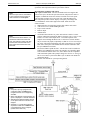
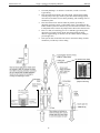
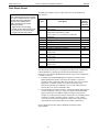
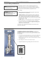
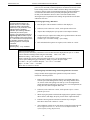
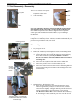
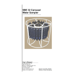
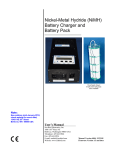
Manual version 015 Section 3: Deploying and Operating SBE 9plus SBE 9plus Vertical Mount • • • • • The main plumbing is 13 mm ID x 19 mm OD (1/2 inch x 3/4 inch) Tygon tubing. Place the intake and exhaust at the same height. Attach exhaust tubing from the pump to the cage. Failure to place the exhaust tubing properly can lead to acceleration of water in the plumbing, with resulting errors in conductivity data. Place the exhaust as far from the intake as possible, preferably in diagonally opposing corners, so that exhaust water is not pulled into the intake. Failure to place the exhaust away from the intake can lead to errors in temperature data, because the pump transfers heat to the exhaust water. Place a 13 mm (0.5 inch) long piece of 9.5 mm ID Tygon tubing at the dissolved oxygen (DO) sensor intake and exhaust. Slide the larger diameter Tygon tubing (13 mm ID) over the smaller diameter tubing to provide tight seals. If the system does not include a DO sensor, connect the tubing from the conductivity cell directly to the Y-fitting. Air release valve detail 0.5 mm (0.02 in.) Note: Periodically clean air release valve to ensure proper functioning. 15 Manual version 015 Section 3: Deploying and Operating SBE 9plus SBE 9plus Horizontal Mount • • • • • • The main plumbing is 13 mm ID x 19 mm OD (1/2 inch x 3/4 inch) Tygon tubing. Place the DO sensor intake above the conductivity sensor exhaust. Place the pump intake above the DO sensor exhaust. Orient the pump with the exhaust outlet corner up. Place a 13 mm (0.5 inch) long piece of the 9.5 mm ID Tygon tubing at the DO sensor intake and exhaust. Slide the larger diameter tubing (13 mm ID) over the smaller diameter tubing to provide tight seals. If the system does not include a DO sensor, connect the tubing from the conductivity cell directly to the pump intake. 16 Manual version 015 Section 3: Deploying and Operating SBE 9plus SBE 9plus Pump Operation Notes: • The control logic for pump turn-on functions is based on the sensor output on the primary conductivity channel. If the 9plus is equipped with redundant T & C sensors and pumps, and you want to deploy it with the primary conductivity sensor removed, swap the secondary T & C sensor pair to the primary T & C channel bulkhead connectors (JB2 for conductivity, JB1 for temperature). • Sea-Bird sets the minimum conductivity frequency for pump turn-on to well above the zero conductivity frequency, to prevent the pump from turning on in air as a result of small drifts in the electronics. As a result, the standard 9plus is not suitable for use in fresh water, because the conductivity frequency of fresh water is just slightly above the zero conductivity frequency and therefore the pump will not turn on. Optional modifications are available for fresh water use. See SBE 9plus with Manual Pump Control and SBE 9plus with Water Contact Pump Control below. Notes: • With the manual pump control feature installed, you must remember to turn the pump on; it will not turn on automatically. • See the SBE 11plus manual for details on operating the pump with the manual pump control feature installed in the 9plus. Note: With the water contact pump control feature installed, you must inspect the contact pin periodically for corrosion; corrosion may prevent the pump from turning on. For a standard SBE 9plus, pump turn-on occurs when two conditions are met: • Raw conductivity frequency exceeds minimum conductivity frequency Sea-Bird hard wires the minimum conductivity frequency for pump turn-on to a value above the 9plus zero conductivity raw frequency (see SBE 4C calibration sheet), to prevent pump turn-on when the 9plus is in air. A typical value for pump turn-on is approximately 3500 Hz. • Pump turn-on delay time (60 seconds) has elapsed The pump turn-on delay allows time for all the air in the Tygon tubing and pump to escape after the 9plus is submerged. If the pump turns on when there is air in the impeller housing, priming is uncertain and a proper flow rate cannot be ensured. When deploying, soak the instrument just under the surface for at least 1 minute before beginning the downcast, allowing time for the SBE 9plus to determine that the conductivity frequency exceeds the zero conductivity frequency and for the subsequent 60-second pump turn-on delay. The tubing above the air-bleed hole (9plus vertical orientation only) contains a small reserve of water. This maintains pump prime (for up to 1 minute, depending on length of tubing above air-bleed), even if the 9plus is lifted up so that the cell inlet and pump outlet are just below the water surface. This allows beginning the actual profile very near the top of the water. The cell inlet and pump outlet must not come above the water surface or prime will be lost. • If prime is lost, turn off power to the 9plus (via the Deck Unit or SEARAM as applicable). Restore power, submerge the 9plus completely, and wait for at least 1 minute before beginning the downcast. Failure to allow sufficient soak time for pump turn-on will result in poor quality data at the top of the profile for any sensors plumbed with the pump (conductivity, optional dissolved oxygen, etc.). SBE 9plus with Manual Pump Control An SBE 9plus with optional manual pump control allows you to turn the pump on and off via commands from Seasave, which can be useful for fresh water applications. Pump control commands are sent through the SBE 11plus Deck Unit Modem Channel connector, but pump control does not interfere with water sampler operation. Seasave V7 supports this feature from within the user interface (enable/disable manual pump control on the Pump Control tab in the Configure Inputs dialog box; turn the pump on and off from the Real-Time Control menu). Earlier versions of Seasave supported this feature if the software was started with the –pc option from the command line. SBE 9plus with Water Contact Switch Pump Control An SBE 9plus with optional water contact pump control allows the pump to automatically turn on 60 seconds after a contact pin is immersed in water (salt or fresh), and automatically turn off when the contact pin is removed from the water. This feature can be useful for fresh water applications, since the pump control is independent of the water conductivity. The contact pin is on a special dummy plug that connects to JB6 on the 9plus bottom end cap; modifications to the 9plus internal wiring to JB6 for this feature prevent use of JB6 for a bottom contact switch. 17 Manual version 015 Section 3: Deploying and Operating SBE 9plus SBE 9plus Bottom Contact Switch Note: All SBE 9plus CTDs manufactured after February 2007 have a 2-pin female bulkhead connector for JB6 to differentiate JB6 from the JT1 sea cable connector. Earlier versions used a 2-pin male bulkhead connector for JB6. See Application Note 86 for details on the change, and information on retrofitting existing CTDs if desired. Note: The Deck Unit’s alarm and Seasave do not require any setup for the bottom contact switch. However, if you are using an SBE 14 Remote Display connected to the computer, and you want the Remote Display alarm to ring in response to the bottom contact switch, you must enable the bottom contact switch alarm on the SBE 14 Remote Display tab in Seasave’s Configure Outputs. An optional bottom contact switch can be used with the SBE 9plus (with the SBE 11plus V2 Deck Unit) to provide an early warning that the CTD package is nearing the ocean floor. The bottom contact switch module includes: • switch • mounting kit – three kits are available, for mounting switch to 9plus housing, 9plus cage, or SBE 32 Carousel Water Sampler cage • cable to connect to JB6 at the center of the 9plus bottom end cap • 0.9 kg (2 lb) lead ball • length of heavy line – cut to desired length based on amount of warning you want that CTD package is nearing ocean floor The switch remains open (no current flow) when the lead ball pulls on the switch arm. When the ball reaches the ocean floor, the weight is removed from the arm and the switch closes. This sets a bit in the 9plus data stream, which causes an alarm to turn on in the 11plus V2 Deck Unit. To prevent the alarm from sounding while the package is sitting on deck (i.e., before the weight of the ball is applied to the switch), insert a small piece of non-conductive material (such as Tygon tubing) in the switch to hold the switch open. When deploying the system, remember to remove the non-conductive material once the weight of the ball is applied to the switch. Lower the lead ball carefully into the water. Do not just drop the ball, or you may damage the switch. Similarly, use care on recovery. Tygon tubing or other nonconductive material to hold switch open while on deck Bottom contact switch 18 Manual version 015 Section 3: Deploying and Operating SBE 9plus SBE 9plus Optimizing Data Quality Our deployment recommendations are only general guidelines, and are focused primarily on maximizing data quality. Actual sea state conditions, and winch and deck gear configurations, may require some adaptation to achieve best data quality and avoid mechanical problems. The SBE 9plus is optimized for profiling rates of 0.5 to 2 m/second, with 1 m/second generally providing the best compromise between data quality and profile resolution. The pump maintains a constant and optimum flow rate, which ensures that the sensor response times are independent of descent rate. Adjust the 9plus descent rate based on the amount of ship motion (i.e., sea state) imparted to the cable, and the size, weight, and drag of the underwater package at the end of the cable. Generally, use a faster lowering rate in rougher seas, allowing the 9plus to stay clear of turbulent wakes that are shed downward when the ship heaves up; shed wakes are an error source from which all CTDs suffer. When the sea is very calm, the 9plus can be lowered more slowly (for example, 10 to 20 cm/second) for greater vertical resolution. Like for other CTDs, common 9plus configurations are intended for obtaining downcast data; the sensors are oriented so the T-C Duct inlet passes through relatively undisturbed water as the CTD is lowered. As the CTD is raised (upcast), the sensors sample the turbulent wake of the package, resulting in lower quality data. If planning to sample on the upcast, consider the following: • Vertical orientation - The sensors are in the wake of the main housing on the upcast, providing poor data quality. Because the T and C sensors and pump are modular, it is possible to mount redundant T and C sensors and pump remotely on the upper and lower ends of the frame; one T&C sensor pair can see undisturbed water on the downcast and the other pair can see undisturbed water on the upcast. • Horizontal orientation (for example, under SBE 32 Carousel Water Sampler) - Upcast data is improved somewhat because the sensors are mounted as close as possible to the outside edge of the package. Position other instruments, sample bottles, etc. so that they are not directly above the T & C sensors and do not thermally contaminate the water that flows to the sensors at the T-C Duct inlet. When a 9plus is installed on a water sampler, good conductivity and optional dissolved oxygen data can be collected, even when stopped to collect a water sample, because water continues to flow through the sensors at a fixed and optimal rate. Whether sampling on the upcast and/or downcast, position the T-C Duct inlet so that other instruments, sample bottles, etc. do not thermally contaminate the water that flows past the sensors. Note: See Pump Operation for information on the minimum soak time required to ensure proper pump operation. Where the water temperature is very different from the temperature at which the 9plus has been stored, better results are obtained if the 9plus equilibrates to the water temperature at the surface (soak) for several (3 - 5) minutes before beginning the profile. The reason is not that the electronics are temperature sensitive (they are not), but that the thermal influence of the instrument housing on the water entering the cell will be reduced. If the difference between water and storage temperature is extreme, allow more soak time. When very heavy seas cause severe ship motion, the 9plus descent can actually stop or reverse direction if the ship heaves upward faster than the package can descend. This is often seen as loops in the real-time temperature trace. If the winch payout rate is too high, a loop of wire can form under water when the package descent is slowed or reversed by ship heave and the winch is still paying out wire. Inevitably, the loop formation gets out of phase with the heave 19 Manual version 015 Section 3: Deploying and Operating SBE 9plus SBE 9plus and the loop closes on itself when the ship heaves, causing a kink. If the package includes a water sampler as well as the CTD, the package creates much more drag than with only the CTD, further increasing the possibility of a loop forming in the cable. After 1000 to 2000 meters of cable are paid out, it can be difficult or impossible to detect a loop in the cable. Adding 100 to 200 kg (maybe more by experimentation) of lead weights to the Carousel frame will help overcome the effect of drag, and allow the package to descend faster and stay more in line directly below the overboarding sheave. Spiking is sometimes seen in the derived values for salinity, density, or sound velocity. Spiking results largely from a response time mismatch of the conductivity and temperature sensors, especially when the profiling descent rate is non-uniform. Much of the spiking can be removed by aligning the data in time. This alignment is done automatically by the Deck Unit based on user-input time alignments and selected sensors (conductivity, oxygen, etc.). A rough alignment of primary and secondary conductivity only is done automatically in the SEARAM, based on user-input parameters. More precise alignment can be performed when post-processing data in SBE Data Processing. Note: See SBE Data Processing’s Help files for information on data processing modules that can correct data for the influences of ship motion and minimize salinity spiking. The amount of spiking depends on the temperature gradient, and is much worse when coupled surface motion causes the instrument to stop - or even reverse - its descent. In the event of heavy ship motion, it may be worth letting the instrument free-fall. When very heavy seas cause severe ship motion and result in periodic reversals of the instrument descent, the data set can be greatly improved by removing scans taken when the pressure is not increasing, using SBE Data Processing. Wiring System – Use with SBE 11plus V2 Deck Unit Note: See the Deck Unit manual for recommendations on sea cable, winch, and deck gear, which are not supplied by Sea-Bird. Sea cable from SBE 9plus to Deck Unit Lab Testing Connect the SBE 9plus to the Deck Unit with the supplied test cable. WARNING! Life threatening voltage (+250 VDC) is present on the sea cable when the Deck Unit is powered. This voltage persists for up to 1 minute after removing power. Verify that the sea cable is disconnected from the Deck Unit and the AC power cord is unplugged from the Deck Unit. Wait 1 minute after power is removed before splicing the pigtail to the sea cable. CAUTION: Do not confuse JT1 on the top end cap with either of the 2-pin connectors on the bottom end cap (pressure sensor end). JB3 is the pump connector and JB6 is for a bottom contact switch. Connecting power via the sea cable to JB3 or JB6 will cause serious damage to the 9plus. Deployment A 2-pin pigtail cable is connected to the 2-pin sea cable connector (JT1) on the SBE 9plus top end cap at time of shipment. If your sea cable is not terminated with an equivalent connector, make a waterproof splice to connect the pigtail to your sea cable. Positive power ( +, cable inner conductor) goes to the small pin (black wire on the pigtail), and negative ( -, cable armor) power goes to the large pin (white wire on the pigtail). • If you inadvertently connect power with the wrong polarity, no damage will be done, because there is a protective diode in series with the + power line. The 9plus will not work, however, until the condition is corrected. For safety and for most reliable performance, Sea-Bird strongly recommends use of the cable armor for the CTD power / data return. See the Deck Unit manual for connection of the sea cable to the Deck Unit and wiring of the Deck Unit to the computer, power, and auxiliary equipment. On the ship, cables longer than 3 meters should be installed inside an earthed metal conduit by a qualified electrician. This minimizes the potential for external signals to disrupt communication and ensures that high voltage lines (such as the sea cable) are sufficiently protected. Cables shorter than 3 meters can be used without shielding when installing or bench testing the instrument. 20 Manual version 015 Section 3: Deploying and Operating SBE 9plus SBE 9plus SBE 9plus to Auxiliary Sensors Connect the auxiliary sensors (up to 8 auxiliary sensors) to JT2, JT3, JT5, and JT6 on the SBE 9plus top end cap. Each connector interfaces with up to two auxiliary sensors. Connection of the auxiliary sensors to the 9plus must correspond to the instrument configuration in the .xmlcon or .con file (see Setup for Deployment). SBE 9plus to Water Sampler Note: 300 baud modem interfaces are required in the 9plus and 11plus V2 Deck Unit for operation with a water sampler. The interface, now standard in both the Deck Unit and CTD, was optional in Deck Units with serial number 700 and lower and in 9plus CTDs with serial number 785 and lower. • • • SBE 32 Carousel - Connect the 9plus 6-pin top center JT7 connector to the 6-pin bulkhead connector at the bottom of the Carousel electronics housing with the 6-pin to 6-pin jumper cable. G.O. 1015 Rosette - Connect the 9plus 3-pin JT4 connector to the Rosette. The G.O. 1015 has 2 polarity settings, normal and reverse, which refer to the sea cable polarity. Most commonly, it is set to reverse, especially when used with a MK III CTD. The 9plus can be used with the G.O. 1015 in either setting by choosing the appropriate interface cable: 17196 for reverse or 17533 for normal. If you have only one interface cable, the polarity setting of the G.O. 1015 can be changed to correspond with your cable (see Application Note 35). G.O. 1016 Rosette - Connect the 9plus 6-pin top center JT7 connector to the Rosette. Wiring System – Use with SBE 17plus V2 SEARAM CAUTION: The SEARAM has no clamp or voltage drop circuitry to limit supply voltage to the 9plus. Thus, the voltage supplied by the SEARAM’s power supply is the voltage supplied to the 9plus, which is also the voltage supplied by the 9plus to all its auxiliary sensors. Some auxiliary sensors, such as WET Labs ECO sensors, are limited to input voltages less than 15 volts. Twelve fully charged batteries in the SEARAM supply the following voltage: • NiMH or Ni-Cad - 14.4 volts • Alkaline - 18 volts Using alkaline batteries in the SEARAM for 9plus deployments including lower input voltage sensors can damage the sensors. Note: 300 baud modem interface is required in the 9plus for operation with a water sampler. The interface, now standard, was optional in 9plus CTDs with serial number 785 and lower. SBE 9plus to SEARAM Connect the SBE 9plus 6-pin JT7 to the SEARAM 6-pin connector (clockwise from the switch plunger) using the supplied cable. SBE 9plus to Auxiliary Sensors Connect the auxiliary sensors (up to 8 auxiliary sensors) to JT2, JT3, JT5, and JT6 on the SBE 9plus top end cap. Each connector interfaces with up to two auxiliary sensors. Connection of the auxiliary sensors to the 9plus must correspond to the instrument configuration in the .xmlcon or .con file (see Setup for Deployment). SBE 9plus to Water Sampler Connect the water sampler to the SEARAM, not to the SBE 9plus (see the SEARAM manual). 21 Manual version 015 Section 3: Deploying and Operating SBE 9plus SBE 9plus Wiring System – Use with Both SBE 11plus V2 Deck Unit and 17plus V2 SEARAM Note: The SEARAM cannot be used to control a water sampler with this scheme; the water sampler (if used) is controlled via the Deck Unit or Seasave. It is possible to use the SEARAM to record 9plus data in memory at the same time as the 9plus data is transmitted real-time through the 11plus Deck Unit. This provides a data back-up in case there are data transmission problems over the sea cable. Start data acquisition through the Deck Unit, as described in the Deck Unit manual. Then, start saving data to the SEARAM memory by pushing in the SEARAM’s switch plunger. Sea Cable from SBE 9plus to Deck Unit Connect as described above in Wiring System – Use with SBE 11plus V2 Deck Unit. SBE 9plus to Auxiliary Sensors Connect as described above in Wiring System – Use with SBE 11plus V2 Deck Unit. SBE 9plus to SEARAM and (if applicable) Water Sampler Without a water sampler: Connect the 9plus 6-pin JT7 to the SEARAM 6-pin connector (clockwise from the switch plunger) using the supplied cable. With a Carousel Water Sampler: With a Y-cable, connect - 9plus 6-pin JT7 pins 1 and 4 to the SEARAM 6-pin connector (clockwise from the switch plunger). - 9plus 6-pin JT7 pins 1, 2, 3, and 6 to the 6-pin bulkhead connector at the bottom of the Carousel electronics. Wiring System – Use with Optional RS-232 Serial Output Interface When the SBE 9plus is ordered with an optional RS-232 serial output interface installed in placed of the standard G.O. 1015 interface, it can transmit 9plus data through the JT4 connector on the 9plus top end cap at 19,200 baud, 8 data bits, and no parity. This option is typically desired when an AUV / ROV is providing power to the 9plus and is logging 9plus data. A computer running Seasave will be able to display and archive the data directly from the 9plus; no SBE 11plus Deck Unit is required. SBE 9plus to RS-232 Data Logger and Power Supply Connect the SBE 9plus optional serial output 3-pin JT4 on the top end cap to the equipment logging the RS-232 serial data, using the supplied pigtail cable. Note: If desired, the 9plus can be powered through the sea cable JT1 connector instead of JT4. For wiring details, see Sea Cable from SBE 9plus to Deck Unit in Wiring System – Use with SBE 11plus V2 Deck Unit above. Power (12 – 16V) is also supplied to the 9plus through JT4 (typical for operation with an AUV / ROV). The voltage supplied to the 9plus by the power supply will be the voltage supplied by the 9plus to all the sensors. Ensure that you are supplying appropriate voltage and power to operate the 9plus as well as all the sensors. 22 Manual version 015 Section 3: Deploying and Operating SBE 9plus SBE 9plus SBE 9plus to Auxiliary Sensors Connect the auxiliary sensors (up to 8 auxiliary sensors) to JT2, JT3, JT5, and JT6 on the SBE 9plus top end cap. Each connector interfaces with up to two auxiliary sensors. Connection of the auxiliary sensors to the 9plus must correspond to the instrument configuration in the .xmlcon or .con file (see Setup for Deployment). Ballast Weights Note: Remove ballast weights from the cage for shipping. When making deep casts, working in heavy seas (see Optimizing Data Quality above), or working on large ships with heavy-duty winches, use additional weight on the SBE 9plus cage. Bolt the weights to the side rails of the cage as close to the bottom as possible. Setup for Deployment Notes: • Seasave and SBE Data Processing versions 7.20 introduced .xmlcon files (in XML format). Versions 7.20 and later allow you to open a .con or .xmlcon file, and to save it to a .con or .xmlcon file. Seasave and SBE Data Processing use the same configuration file. • A new or recalibrated CTD ships with a configuration file that reflects the current configuration as we know it. The file is named with the instrument serial number, followed by a .con extension. For example, for a CTD with serial number 2375, Sea-Bird names the file 2375.con. You may rename the file (but not the extension) if desired; this will not affect the results. 1. Verify that the configuration (.xmlcon or .con) file matches the instrument configuration. The configuration file defines the instrument – auxiliary sensors, and channels, serial numbers, and calibration dates and coefficients for all sensors. Seasave and SBE Data Processing use the configuration file to interpret and process the raw data. If a sensor is recalibrated or the configuration is changed (such as by adding auxiliary sensors), the configuration file must be updated. If the .xmlcon or .con file does not match the instrument configuration, the software will not interpret and process raw data correctly. View and edit the file in Seasave or SBE Data Processing; details are provided for Seasave: A. Double click on Seasave.exe. B. Click Configure Inputs. On the Instrument Configuration tab, click Open. In the dialog box, select the .xmlcon or .con file and click Open. 23 Manual version 015 Section 3: Deploying and Operating SBE 9plus SBE 9plus C. The configuration information appears on the Instrument Configuration tab. Verify that the sensors match those on your instrument, and that auxiliary sensors are assigned to the correct channels. Click Modify to bring up a dialog box (shown below) to change the configuration and/or to view/modify calibration coefficients. Channel/Sensor table reflects this choice. Typically: • 0 = SBE 3plus or 4C plugged into JB5 (COND 2) on 9plus (dual redundant sensor configuration) • 1 = SBE 3plus or 4C plugged into JB4 (TEMP 2) on 9plus and not using JB5 (COND 2) connector (single redundant sensor configuration) • 2 = no redundant T or C sensors Channel/Sensor table reflects this choice. Voltage 0 in .con or .xmlcon file corresponds to sensor wired to channel 0 on end cap connector, voltage 1 to sensor wired to channel 1 on end cap connector, etc. Total voltage words = 4; each word contains data from two 12-bit A/D channels. 11plus V2 suppresses words above highest numbered voltage word used. Number of words to keep is determined by highest numbered external voltage input that is not a spare: Words to suppress = 4 - Words to Keep External Voltage (not spare) 0 or 1 Connector JT2: AUX1 Words to Keep 1 11plus > 5.0: Seasave sends AddSpar= command to 11plus, consistent with configuration file selection for Surface PAR. 11plus < 5.0: Surface PAR acquisition is set in 11plus with dip switch. 17plus: Real-time data acquisition not available, only playback of archived data. None: Not using 11plus or 17plus; see Seasave manual. • NMEA - Select if NMEA navigation device used, and select whether NMEA device is connected directly to 11plus Deck Unit or to computer. If NMEA navigation device connected to computer, you can also append NMEA depth data (3 bytes) and NMEA time data (4 bytes) after Lat/Lon data. Seasave adds current latitude, longitude, and universal time code to data header; appends NMEA data to every scan; and writes NMEA data to .nav file every time Ctrl F7 is pressed or Add to .nav File is clicked. See Section 6: Setting Up NMEA Interface. • Surface PAR - Select if Surface PAR sensor used; ; must agree with Deck Unit setup if 11plus firmware < 5.0. Seasave appends Surface PAR data to every scan. Adds 2 channels to Channel/Sensor table. Do not decrease Voltage words suppressed to reflect this; Voltage words suppressed reflects only external voltages going directly to 9plus from auxiliary sensors. • Scan time - Select to have Seasave append time (seconds since January 1, 1970 GMT) to each data scan. 2 or 3 JT3: AUX2 2 4 or 5 JT5: AUX3 3 6 or 7 JT6: AUX4 4 IEEE-448 or RS-232C for CTD data interface between Deck Unit and computer. For full rate (24 Hz) data, set to 1. Example: If scans to average=24, Seasave averages 24 scans, saving to computer at 1 scan/second. Shaded sensors cannot be removed or changed to another type; others are optional. Click a (non-shaded) sensor and click Select to pick a different sensor for that channel; dialog box with list of sensors appears. After sensor is selected, dialog box for calibration coefficients appears. Select sensors after Frequency channels suppressed and Voltage words suppressed have been specified above. Click a sensor and click Modify to view/change calibration coefficients for that sensor. D. Click Save or Save As to save any changes to the .xmlcon or .con file. Click Exit when done reviewing / modifying the configuration file. 2. Program the system for the intended deployment: • Deck Unit with 9plus - use SEATERM (see Deck Unit manual) • SEARAM with 9plus - use SeatermAF (see SEARAM manual) 24 Manual version 015 Section 3: Deploying and Operating SBE 9plus SBE 9plus Deployment 1. Install a cable or dummy plug for each connector on the main housing end cap: A. Lightly lubricate the inside of the dummy plug/cable connector with silicone grease (DC-4 or equivalent). B. Standard Connector- Install the plug/cable connector, aligning the raised bump on the side of the plug/cable connector with the large pin (pin 1 - ground) on the 9plus. Remove any trapped air by burping or gently squeezing the plug/connector near the top and moving your fingers toward the end cap. OR MCBH Connector – Install the plug/cable connector, aligning the pins. C. Place the locking sleeve over the plug/cable connector. Tighten the locking sleeve finger tight only. Do not overtighten the locking sleeve and do not use a wrench or pliers. 2. Connect the other end of the cables installed in Step 1 to the appropriate sensors. 3. Verify that the hardware and external fittings are secure. 4. If applicable, remove the Tygon tubing that was looped end-to-end around the conductivity cell for storage. Reconnect the conductivity cell to the 9plus plumbing. 5. See the Deck Unit or SEARAM manual for details on starting data acquisition. CAUTION: Do not use WD-40 or other petroleum-based lubricants, as they will damage the connectors. The SBE 9plus is ready to go into the water. 25 Manual version 015 Section 3: Deploying and Operating SBE 9plus SBE 9plus Recovery WARNING! If the 9plus stops working while underwater, or shows other signs of flooding or damage, carefully secure it away from people until you have determined that abnormal internal pressure does not exist or has been relieved. Pressure housings may flood under pressure due to dirty or damaged o-rings, or other failed seals. When a sealed pressure housing floods at great depths and is subsequently raised to the surface, water may be trapped at the pressure at which it entered the housing, presenting a danger if the housing is opened before relieving the internal pressure. Instances of such flooding are rare. However, a housing that floods at 5000 meters depth holds an internal pressure of more than 7000 psia, and has the potential to eject the end cap with lethal force. A housing that floods at 50 meters holds an internal pressure of more then 85 psia; this force could still cause injury. If you suspect the 9plus is flooded, point the 9plus in a safe direction away from people, and loosen the 6 screws on the top end cap about ½ turn. If there is internal pressure, the end cap will follow the screws out, and the screws will not become easier to turn. In this event, loosen 1 top end cap bulkhead connector very slowly, at least 1 turn. This opens an o-ring seal under the connector. Look for signs of internal pressure (hissing or water leak). If internal pressure is detected, let it bleed off slowly past the connector o-ring. Then, you can safely remove the end cap. 1. Rinse the 9plus with fresh water. See Section 4: Routine Maintenance and Calibration for conductivity cell cleaning and storage. 2. If using the 9plus with the SEARAM, upload data from the SEARAM memory. Ensure all data has been uploaded by reviewing and processing the data before resetting the memory. 3. Use SBE Data Processing to process the .hex data from the Deck Unit or SEARAM (see SBE Data Processing Help files). Note: Seasave V7 creates a .hex file from data from the Deck Unit. Earlier Seasave versions created a binary .dat file. 26 Manual version 015 Section 3: Deploying and Operating SBE 9plus SBE 9plus Data Output Format Note: Data output through the JT4 connector for a 9plus configured with the optional RS-232 serial output interface is identical to the output from the SBE 11plus Deck Unit, with the following exception: • Alignment and any averaging, typically done in the Deck Unit, must be performed in post-processing if using the RS-232 serial output. The SBE 9plus outputs 36 bytes of data in raw form as described below. The format is: Byte 1 2 3 4–6 7–9 10 – 12 13 – 15 16 – 18 19 – 21 22 – 24 25 – 27 28 – 30 31 – 36 Description 8 MSB of pressure sensor temperature compensation 4 LSB of pressure sensor temperature compensation; status bits for pump, bottom contact, G.O. 1015 Rosette confirm bit, and modem Modulo count Primary temperature frequency Primary conductivity frequency Pressure frequency Secondary temperature frequency Secondary conductivity frequency Voltage output from A/D channels 0 - 1 (12 bits each) Voltage output from A/D channels 2 - 3 (12 bits each) Voltage output from A/D channels 4 - 5 (12 bits each) Voltage output from A/D channels 6 - 7 (12 bits each) Expansion (all zeros) Main Housing End Cap Connector - JB1 JB2 JB4 JB5 JT2 JT3 JT5 JT6 - The data output from the 9plus is rearranged in the Deck Unit or SEARAM. Unused channels are suppressed in the data stream transmitted by the Deck Unit or stored in the SEARAM, based on the setup of the configuration (.xmlcon or .con) file. • The Deck Unit and SEARAM suppress frequency words above the highest numbered frequency word used. For example, if you have a secondary sensor connected to JB4 but not to JB5, bytes 16 to 18 will be suppressed. As another example, if you have a secondary sensor connected to JB5, but not to JB4, bytes 13 to 15 will contain all zeros, because there is no sensor connected to JB4. • The total number of voltage words is 4; each word contains data from two 12-bit A/D channels (3 bytes per word). The Deck Unit and SEARAM suppress words above the highest numbered voltage word used. For example, if you have auxiliary sensors connected to JT2 (Auxiliary Sensor Connector 1) and JT5 (Auxiliary Sensor Connector 3), only voltage word 4 (bytes 28-30) will be suppressed; voltage word 2 (bytes 22-24) will contain all zeros, because there are no sensors connected to it. See the manual for the Deck Unit or SEARAM for details on their output formats. 27 Manual version 015 Section 4: Routine Maintenance and Calibration SBE 9plus Section 4: Routine Maintenance and Calibration This section reviews corrosion precautions, connector mating and maintenance, plumbing air valve maintenance, conductivity cell storage and cleaning, pressure sensor maintenance, sensor calibration, and TC Duct disassembly. The SBE 9plus accuracy is sustained by care and calibration of the sensors and establishment of proper handling practices. Corrosion Precautions Rinse the SBE 9plus with fresh water after use and prior to storage. Aluminum Main Housing The housing is insulated from the stainless steel guard cage and sea cable power circuits, preventing heavy corrosion of the housing. Avoid direct attachment of metal objects to the housing. All stainless steel screws that are exposed to salt water have been generously lubricated with Blue MolyTM, a molybdenum lubricant containing nickel power and zinc oxide. After each cruise, remove these screws and re-lubricate. This compound is electrically conductive; use care to ensure it does not get on PCBs. Note: Sea-Bird recommends that you replace an anode when more than 50% of the material has eroded. The SBE 9plus has three large zinc anodes screwed into the main housing top end cap. Check the anodes periodically to verify that they are securely fastened and have not been eaten away. Once a year, remove the stainless steel hose clamps and PVC mounting chocks to clean the entire housing surface; this will prevent long-term breakdown of the surface. We recommend periodic replacement of the clamps; use Teflon tape or similar material between the clamps and the anodized housing surface. Optional Titanium Main Housing All exposed metal and hardware are titanium. No corrosion precautions are required, but avoid direct electrical connection of the titanium to dissimilar metal hardware. Ring-shaped anode Modular Sensors and Auxiliary Equipment The modular temperature and conductivity sensors, as well as auxiliary sensors manufactured by Sea-Bird that have an aluminum housing (SBE 18, SBE 27, etc.), have a ring-shaped zinc anode. Check the anodes periodically to verify that they are securely fastened and have not been eaten away. Auxiliary equipment powered from the SBE 9plus should ideally have a floating housing relative to their power circuits. It is permissible to have CTD power and/or signal common lines connected to auxiliary equipment housing. However, do not connect the auxiliary equipment housing to the 9plus 15-volt power source, as this can destroy the conductivity cell electrodes. 28 Manual version 015 Section 4: Routine Maintenance and Calibration SBE 9plus Connector Mating and Maintenance Note: See Application Note 57: Connector Care and Cable Installation. Clean and inspect connectors, cables, and dummy plugs before every deployment and as part of your yearly equipment maintenance. Inspect connectors that are unmated for signs of corrosion product around the pins, and for cuts, nicks or other flaws that may compromise the seal. When remating: CAUTION: Do not use WD-40 or other petroleum-based lubricants, as they will damage the connectors. 1. Lightly lubricate the inside of the dummy plug/cable connector with silicone grease (DC-4 or equivalent). 2. Standard Connector - Install the plug/cable connector, aligning the raised bump on the side of the plug/cable connector with the large pin (pin 1 - ground) on the 9plus. Remove any trapped air by burping or gently squeezing the plug/connector near the top and moving your fingers toward the end cap. OR MCBH Connector – Install the plug/cable connector, aligning the pins. 3. Place the locking sleeve over the plug/cable connector. Tighten the locking sleeve finger tight only. Do not overtighten the locking sleeve and do not use a wrench or pliers. Verify that a cable or dummy plug is installed for each connector on the system before deployment. Plumbing Maintenance For an SBE 9plus deployed in a vertical orientation A clogged air release valve can trap air, preventing the pump from functioning properly; this will affect the data quality. Periodically clean the air release valve: Y-fitting with air release valve 1. Use a 0.4 mm (0.016 inches) diameter wire (you can use #26 AWG wire) to clean the valve. The easiest way to do this is to remove the Tygon tubing above the air release valve, and use needle-nosed pliers to force the wire through the hole. 2. Blow through the air release valve to ensure it is open. 3. (if applicable) Replace the Tygon tubing above the air release valve. Air release valve detail 0.5 mm (0.02 in.) 29 Manual version 015 Section 4: Routine Maintenance and Calibration SBE 9plus Conductivity Cell Maintenance CAUTIONS: • Do not put a brush or any object inside the conductivity cell to dry it or clean it. Touching and bending the electrodes can change the calibration. Large bends and movement of the electrodes can damage the cell. • Do not store the SBE 4C with water in the conductivity cell. Freezing temperatures (for example, in Arctic environments or during air shipment) can break the cell if it is full of water. The SBE 4C conductivity cell is shipped dry to prevent freezing in shipping. Refer to Application Note 2D: Instructions for Care and Cleaning of Conductivity Cells for conductivity cell cleaning and storage procedures and materials. Sea-Bird supplies a conductivity cell filling and storage kit to use in rinsing and cleaning the cell. Disconnect the plumbing from the conductivity cell to use the filling and storage kit. Conductivity sensor Conductivity quick disconnect – press metal lever and disconnect plumbing from cell to loop Tygon tubing to each end of cell Do not remove TC Duct for rinsing, cleaning, or storage – attach Tygon tubing to end of TC Duct to loop Tygon tubing to each end of cell Conductivity sensor Pressure Sensor Maintenance The nylon pressure capillary fitting – which includes a pressure port fitting and an external capillary tube – is filled with silicone oil. The oil transmits hydrostatic pressure via internal, stainless steel, capillary tubing to the pressure sensor inside the instrument, and prevents corrosion that might occur if the sensor diaphragm was exposed to water. The internal tubing and nylon capillary fitting are vacuum back-filled at the factory. Pressure sensor port Main Housing Bottom End Cap Because of the viscosity of the silicone oil and capillary action, the silicone oil does not run out of the external capillary tube. However, due to temperature and pressure cycling over long periods, it is normal for some oil to slowly leak out of the external capillary tube. When the oil is not visible or is receding inside the translucent tube, or if the fitting has been damaged, refill the oil using the supplied pressure sensor oil refill kit. See Application Note 12-1: Pressure Port Oil Refill Procedure & Nylon Capillary Fitting Replacement. Pump Maintenance See Application Note 75: Maintenance of SBE 5T, 5P, and 5M Pumps. 30 Manual version 015 Section 4: Routine Maintenance and Calibration SBE 9plus Sensor Calibration Note: After recalibration, Sea-Bird ships the sensors back to the user with an updated configuration (.xmlcon) file and Calibration Certificates showing the new coefficients. Sea-Bird sensors are calibrated by subjecting them to known physical conditions and measuring the sensor responses. Coefficients are then computed, which may be used with appropriate algorithms to obtain engineering units. The conductivity, temperature, and pressure sensors on the SBE 9plus are supplied fully calibrated, with coefficients printed on their respective Calibration Certificates (back of manual) and stored in the instrument configuration (.xmlcon or .con) file. We recommend that the 9plus sensors be returned to Sea-Bird for calibration. There is no need to send the 9plus main housing along with the temperature and conductivity sensors. See TC Duct Disassembly / Reassembly below for detailed instructions on removing the sensors. Conductivity The SBE 4C conductivity sensor incorporates a fixed precision resistor in parallel with the cell. When the cell is dry and in air, the sensor’s electrical circuitry outputs a frequency representative of the fixed resistor. This frequency is recorded on the Calibration Certificate and should remain stable (within 1 Hz) over time. The primary mechanism for calibration drift in conductivity sensors is the fouling of the cell by chemical or biological deposits. Fouling changes the cell geometry, resulting in a shift in cell constant. Accordingly, the most important determinant of long-term sensor accuracy is the cleanliness of the cell. We recommend that the conductivity sensor be calibrated before and after deployment, but particularly when the cell has been exposed to contamination by oil slicks or biological material. Temperature The primary source of temperature sensor calibration drift is the aging of the thermistor element. Sensor drift will usually be a few thousandths of a degree during the first year, and less in subsequent intervals. Sensor drift is not substantially dependent on the environmental conditions of use, and — unlike platinum or copper elements — the thermistor is insensitive to shock. Pressure The Paroscientific Digiquartz pressure sensor is so stable and immune to environmental effects that much less frequent checks are required. Techniques are provided below for making small corrections to the pressure sensor calibration using the slope and offset calibration coefficient terms by comparing SBE 9plus pressure output to: • Readings from a barometer - Digiquartz sensors show most of their error as a linear offset from zero. Check the 0 pressure reading from the sensor against the local barometric pressure. • Readings from a dead-weight pressure generator – For especially critical work, on an annual schedule check the pressure sensor full scale response using a dead-weight tester. This provides more accurate results, but requires equipment that may not be readily available. Pressure sensor port (main housing bottom end cap) 31 Manual version 015 Section 4: Routine Maintenance and Calibration SBE 9plus Before using either of these procedures, allow the 9plus to equilibrate (with power on) in a reasonably constant temperature environment for at least 5 hours before starting. Pressure sensors exhibit a transient change in their output in response to changes in their environmental temperature. Sea-Bird instruments are constructed to minimize this by thermally decoupling the sensor from the body of the instrument. However, there is still some residual effect; allowing the 9plus to equilibrate before starting will provide the most accurate calibration correction. Note: The 9plus pressure sensor is an absolute sensor, so its raw output includes the effect of atmospheric pressure (14.7 psi). As shown on the Calibration Sheet, Sea-Bird’s calibration (and resulting calibration coefficients) is in terms of psia. However, when outputting pressure in engineering units, Seasave outputs pressure relative to the ocean surface (i.e., at the surface the output pressure is 0 decibars). Seasave uses the following equation to convert psia to decibars: Pressure (db) = [pressure (psia) - 14.7] * 0.689476 Calculating Offset using a Barometer 1. Place the 9plus in the orientation it will have when deployed. 2. In Seasave, in the .xmlcon or .con file, set the pressure offset to 0.0. 3. Acquire data, and display the 9plus pressure sensor output in decibars. 4. Compare the 9plus output to the reading from a good barometer at the same elevation as the 9plus pressure sensor. Calculate offset = barometer reading – 9plus reading 5. Enter calculated offset (positive or negative) in the .xmlcon or .con file. Offset Correction Example: Absolute pressure measured by a barometer is 1010.50 mbar. Pressure displayed from 9plus is -2.5 dbars. Convert barometer reading to dbars using the relationship: mbar * 0.01 = dbar Barometer reading = 1010.50 mbar * 0.01 = 10.1050 dbar Seasave outputs gage pressure, using an assumed value of 14.7 psi for atmospheric pressure. Convert 9plus reading from gage to absolute by adding 14.7 psia to the 9plus output: -2.5 dbars + (14.7 psi * 0.689476 dbar/psia) = -2.5 + 10.13 = 7.635 dbars Offset = 10.1050 – 7.635 = + 2.47 dbars Enter offset in .xmlcon or .con file. Calculating Slope and Offset using a Dead-Weight Pressure Generator Using a suitable dead-weight pressure generator to subject the sensor to increments of known pressures: 1. Remove the nylon fitting (with short attached 1/8-inch OD plastic tube) from the 9plus main housing bottom end cap. The fitting contains silicon oil, so there will be some spillage. The end cap’s 5/16-24 straight thread permits mechanical connection to a pressure source. Use a fitting that has an O-ring face seal, such as Swagelok 200-1-OR. 2. In Seasave, in the .xmlcon or .con file, set the pressure slope to 1.0 and pressure offset to 0.0. 3. While varying the pressure with the dead-weight pressure generator, acquire data in Seasave, and display the 9plus pressure sensor output in decibars. 4. Perform a linear regression on the data to calculate slope and offset. Enter these values in the .xmlcon or .con file. 5. After calibration, refill the cavity with silicon oil using the supplied oil refill kit (see Application Note 12-1: Pressure Port Oil Refill Procedure & Nylon Capillary Fitting Replacement). 32 Manual version 015 Section 4: Routine Maintenance and Calibration SBE 9plus TC Duct Disassembly / Reassembly Temperature sensor guard Tygon tubing The TC Duct consists of two parts: • T Duct installed in the temperature sensor guard • C Duct assembly C Duct Tygon tubing T Duct C Duct Assembly For sensor shipment, calibration, and acid cleaning, the C Duct must be disconnected from the T Duct and removed from the conductivity cell. Note that the temperature sensor should be shipped with the temperature sensor guard, which includes the installed T Duct, to prevent damage to the thermistor. Conductivity sensor These procedures require slow, deliberate movements to avoid breaking the temperature or conductivity sensor. Therefore, Sea-Bird recommends that you perform these procedures in a lab, not on deck Disassembly 1. Lay the cage on its side. 2. Remove the conductivity and temperature sensors and mounting bracket assembly from the 9plus main housing: A. Unscrew the locking sleeves from the temperature and conductivity sensor cable connectors by hand. If you must use a wrench or pliers, be careful not to loosen the bulkhead connector instead of the locking sleeve. B. Remove the cable connector from each sensor by pulling the connector firmly away from the sensor. C. Remove the quick disconnect from the conductivity cell. D. Remove the two hex head screws that secure the mounting bracket to the 9plus main housing end cap. Remove the mounting bracket from the main housing. 3. Disconnect the T Duct from the C Duct: A. Slowly rotate the temperature sensor guard by turning it counterclockwise approximately 90 degrees. At the same time, rotate the C Duct clockwise slightly. The Tygon tube that joins the ducts flexes and slips off the T Duct as the T Duct twists out of its position. Note: Do not force the C Duct, as this could break the conductivity cell. If rotating the C Duct is difficult, pour water over the duct area to dissolve buildup around the duct. Conductivity quick disconnect – press metal lever and disconnect plumbing from cell Hex-head screws for T & C sensor mounting bracket Conductivity sensor Temperature sensor Temperature sensor guard rotated 90° counterclockwise while C Duct rotated clockwise slightly 33 Manual version 015 Section 4: Routine Maintenance and Calibration 4. Rotate C Duct clockwise SBE 9plus Remove the C Duct from the conductivity cell: A. Carefully rotate the C Duct clockwise more. Do not force the C Duct, as this could break the conductivity cell. If rotating the C Duct is difficult, pour water over the duct area to dissolve buildup around the duct. B. Once loosened, gently pull the C Duct straight out from the conductivity cell. C. Store the C Duct for reinstallation. Pull C Duct straight out from conductivity cell Mounting strap screw 5. Retighten the temperature sensor guard by hand. 6. Loosen the mounting bracket strap screw, and slide the sensor(s) from the bracket. Note that if both sensors are being shipped, the sensors can be shipped in their mounting bracket. 7. If shipping the sensors: A. Rinse the cell with clean, de-ionized water and drain. Remove larger droplets of water by blowing through the cell. Do not use compressed air, which typically contains oil vapor. B. Attach a length of Tygon tubing from one end of the conductivity cell to the other, to prevent dust and aerosols from entering the cell during shipment. Slide sensor(s) out of bracket Reassembly 1. If applicable, reinstall the temperature and conductivity sensors in the mounting bracket: A. Slide the temperature sensor into the sensor mounting bracket until the end of the temperature sensor guard extends beyond the conductivity sensor guard approximately 29 mm (11/8 inch). B. Retighten the mounting strap screw. 2. Reconnect the T Duct and C Duct: A. Rotate the temperature sensor guard counter-clockwise approximately 90 degrees, so the T Duct is out of the way. B. Install the C Duct on the conductivity cell, leaving it in the rotated position described in Step 3 of Disassembly above. C. Slowly rotate the temperature sensor guard back into position. As you rotate, insert the end of the T Duct into the Tygon tubing on the C Duct. Continue to rotate both the temperature sensor guard and the C Duct until the T Duct and C Duct are aligned. Do not apply force perpendicular to the end of the glass conductivity cell, as doing so will break the cell. If the ducts are not aligned, loosen the mounting strap screw slightly and carefully rotate / slide the temperature sensor for better alignment; retighten the screw and repeat Step C. D. Center the Tygon tubing on the joint between the C Duct and T Duct. 3. Reinstall the conductivity and temperature sensors and mounting bracket assembly on the 9plus main housing: A. Reinstall the T & C mounting bracket on the main housing end cap, using the two hex head screws. B. Reinstall the quick-release plug on the conductivity cell. C. Reinstall the cables and locking sleeves. 29 mm (1 1/8 in.) Rotate temperature sensor guard and C Duct into place 34 Manual version 015 Section 5: Troubleshooting SBE 9plus Section 5: Troubleshooting WARNINGS! • Hazardous voltages exist in the 9plus and 11plus V2 when power is on. These voltages persist after power is removed because of capacitor storage. Before working on either unit, remove the power cord from the 11plus V2 and wait 60 seconds. • If the 9plus stops working while underwater or shows other signs of flooding or damage, carefully secure the instrument away from people until it has been determined that abnormal internal pressure does not exist or has been relieved. Pressure housings may flood under pressure due to dirty or damaged o-rings, or other failed seals. When a sealed pressure housing floods at great depths and is subsequently raised to the surface, water may be trapped at the pressure at which it entered the housing, presenting a danger if the housing is opened before relieving the internal pressure. Instances of such flooding are rare. However, a housing that floods at 5000 meters depth holds an internal pressure of more than 7000 psia, and has the potential to eject the end cap with lethal force. A housing that floods at 50 meters holds an internal pressure of more then 85 psia; this force could still cause injury. If you suspect the 9plus is flooded, point the 9plus in a safe direction away from people, and loosen the 6 screws on the top end cap about ½ turn. If there is internal pressure, the end cap will follow the screws out, and the screws will not become easier to turn. In this event, loosen 1 top end cap bulkhead connector at least 1 turn. This opens an o-ring seal under the connector. Look for signs of internal pressure (hissing or water leak). If internal pressure is detected, let it bleed off slowly past the connector o-ring. Then, you can safely remove the end cap. This section reviews common problems in operating the SBE 9plus, and provides the most likely causes and solutions. See the Deck Unit or SEARAM manual, as applicable, for detailed troubleshooting of the system. See Appendix II: Circuitry and the Schematics section for circuitry details. See Appendix III: Electronics Disassembly / Reassembly to access the 9plus electronics. If the data telemetry is correct (Deck Unit data light is on and error light is off) but one or more channels is faulty, see Problem 1 before proceeding with work on the 9plus; the problem may be a defective sensor. All voltages are measured relative to pin 2 of any plug-in PCB; this is main signal / power ground for the 9plus. 35 Manual version 015 Section 5: Troubleshooting SBE 9plus Problem 1: Sensor Problems Each SBE 9plus is shipped with a configuration (.xmlcon or .con) file that matches the configuration of the instrument (number and type of sensors, etc.) and includes the sensor calibration coefficients. • Data with nonsense values may be caused by incorrect instrument configuration in the .xmlcon or .con file. Verify that the settings in the file match the instrument Configuration Sheet, and that sensors are connected to the correct bulkhead connectors. • Data with unreasonable (i.e., out of the expected range) values for a sensor may be caused by incorrect calibration coefficients in the .xmlcon or .con file. Verify that the calibration coefficients in the file match the Calibration Certificates. CAUTION: Each Sea-Bird sensor housing was completely desiccated and backfilled with pure argon prior to factory calibration. Opening the housing introduces humidity (atmospheric water vapor), which will cause an immediate offset to the calibration as well as temporary drift instability. Apparent sensor problems may be the result of trouble with the cables or the 9plus acquisition circuitry. The conductivity and temperature sensors have identical power and output characteristics, and can be swapped to help localize the problem. Although repair of these sensors is possible, it is not likely that repairs can be made without affecting sensor calibration. Our sensors are small and easily replaced in the field; as they are supplied with calibration coefficients, a spare sensor can easily get a failed unit into fully operating and calibrated condition. Conductivity and Temperature Sensors If no output frequency is generated, the Deck Unit displays 0.000 for the defective channel. Swap the cable connections to the temperature and conductivity sensors to verify the operation of the acquisition circuit. If a sensor is defective, swapping sensors puts a sensible frequency into the previously 0.000 reading display. If the frequency is still 0.000 with the sensors swapped: • Disconnect the cable from the sensor connector. The cable voltage between pin 1 (large pin) and pin 3 (pin counterclockwise from pin 1) of the sensor cable should be +14.3 volts. • To confirm the proper functioning of a frequency channel, connect a frequency source (square or sine wave, 2 - 5 volts p-p) to pin 1 (large pin) and pin 2 (pin clockwise from pin 1) of the sensor cable. The Deck Unit should read the frequency of the generator. • Check the sensor separately from the 9plus by connecting a 10 - 20 volt power source to the sensor and observing the frequency output with an oscilloscope. If the problem does not appear to be with the sensor, see Frequency Sensors below. 36 Manual version 015 Section 5: Troubleshooting SBE 9plus Pressure Sensor An internal pressure sensor is mounted inside foam insulation near the bottom of the card file. The red lead should be at +8 volts, the black lead at power common. The blue lead should be connected to Backplane via the small board that the sensor cabling is secured to. A properly operating sensor exhibits a square wave frequency of 32 - 40 kHz at this point. For a discussion of possible fault conditions associated with this and subsequent acquisition circuitry, see Frequency Sensors (T, C, and P) below. Do not perform field repairs on a defective pressure sensor; any repair work must be done at the factory. The temperature compensation of the pressure uses a solid-state (bandgap) temperature sensor embedded in the pressure sensor. This element (Analog Devices type AD590) is a 2-terminal device that generates a current proportional to absolute temperature (1 microamp / °K). The current is input to an op amp on the Modulo 12P PCB; a current of opposite polarity is derived from the VREF / LTC1273 reference and used as an offset source. The current difference is scaled through the 95K ohm precision fixed resistor R10 to create an input to the 12-bit A/D converter, U5. The A/D converter parallel output is strobed into the CD4021 shift registers in preparation for transmission to the Deck Unit. The white lead (from the pressure sensor) goes to -13.5 volts. The orange lead connects to pin 10 of the Modulo 12P PCB. Disconnect this lead and connect through a microammeter to power common. If the sensor is working correctly, the current should be approximately equal (in microamps) to the ambient temperature in °K. If the pressure temperature appears to be OK, check the voltage levels associated with Modulo 12P PCB U3. If the problem does not appear to be with the sensor, see Frequency Sensors below. Frequency Sensors (T, C, and P) Note: For version 1 SBE 3 temperature sensors (older product; serial number below 2000), the sensor signal is 2 volt p-p sine waves of 2800 – 12000 Hz. If the problem does not appear to be in the sensor itself: • Check that the sensor signal is present on the 9plus AP Counter (labeled Temp1, Cond1, Press, Temp2, and Cond2 inside the 9plus) PCB (pins 7 and H on the backplane, on the right edge of the small board that the coax cabling is mounted to). These are 2 volt p-p sine waves of 2800 - 12000 Hz for conductivity, 0.5 volt square waves of 2000 – 6000 Hz for temperature, and 4 volt square waves of 32000 - 40000 Hz for pressure. • Remove that channel’s AP Counter PCB and try one of the other AP Counters (the five PCBs are identical) in the offending channel position. If this restores the signal, the AP Counter PCB has a defective input. • If the AP Counter inputs are OK, try swapping AP Counter PCBs to locate the faulty one. If the problem stays with the same channel, check that the FR, SE, SC, and RESET inputs are active. Voltage Sensor If an A/D channel is giving incorrect readings, verify that the inputs to the A/D PCB (labeled CSAD) multiplexer (pins D, F, H, J, L, 10, 8, 7) are correct. Check for +14.3 and -13.5 volts at the A/D PCB. Look for the SE scan clock at pin 9; this starts the (rapid ~ 50 µs/channel) acquisition of A/D channel data. Verify that the SC shift clock is present at pin 6, and that serial data is present at pin 4. 37 Manual version 015 Section 5: Troubleshooting SBE 9plus Problem 2: Pump Not Working Notes: • The control logic for pump turn-on functions is based on the sensor output on the primary conductivity channel. If the 9plus is equipped with redundant T & C sensors and pumps, and you want to deploy it with the primary conductivity sensor removed, swap the secondary T & C sensor pair to the primary T & C channel bulkhead connectors (JB2 for conductivity, JB1 for temperature). • Sea-Bird sets the minimum conductivity frequency for pump turn-on to well above the zero conductivity frequency, to prevent the pump from turning on in air as a result of small drifts in the electronics. As a result, the standard 9plus is not suitable for use in fresh water, because the conductivity frequency of fresh water is just slightly above the zero conductivity frequency and therefore the pump will not turn on. Optional modifications are available for fresh water use; see SBE 9plus with Manual Pump Control and SBE 9plus with Water Contact Pump Control in Section 3: Deploying and Operating SBE 9plus. The SBE 9plus has a hard-wired pump delay to facilitate pump priming. Pump turn-on is enabled after two conditions are met: • The conductivity cell has filled with seawater, causing the conductivity frequency to rise above the pump turn-on frequency. AND THEN • The 60-second pump turn-on delay has elapsed, allowing sufficient time for air in the tubing to escape through the air bleed-hole. Hold the pump just under the surface with the top of the tubing underwater for at least 1 minute before beginning a profile. Check the pump and connections: • Put salt water (a few ppt is sufficient) in the conductivity cell; you should hear a faint rattling from the pump (extended operation of the pump when not in water will reduce bearing life). The pump is not self-priming, so it cannot lift water through the cell when in air. Pumping of water does not occur until the pump exhaust port (side of impeller assembly) is underwater. • Verify that the pump cable is not damaged and connectors are fully mated. • Unplug the pump from its cable. Apply +12 volts to the pump’s small connector pin, return to the large pin. Verify a current drain of about 300 milliamps and listen for the pump running. Disassemble the 9plus and perform the following tests. • Connect an audio signal generator (approximately 2 volts p-p output) at pin 7 (return to pin H) of the primary conductivity AP Counter PCB (Cond1). Set the generator frequency to about 2500 Hz. Observe the squared signal at U2A output. The voltage at pin L should be 0. Increase the generator frequency to about 4000 Hz. The voltage at pin L should now be 5 volts. If not, the one-shot U3B or the buffer U2B is defective. • Verify that the voltage at Cond1 AP Counter PCB pin L also appears at the Transmitter PCB pin K. 60 seconds after Transmitter PCB pin K goes high, pin L should also go high (to nearly 14.3 volts). If this is the case, the problem is in the wiring to the pump external connector. 38 Manual version 015 Section 5: Troubleshooting SBE 9plus Problem 3: SBE 9plus Completely Inoperative SBE 9plus with Deck Unit The Deck Unit may not be supplying the proper sea cable voltage (250 volts). Check the Deck Unit rear panel fuse. Check the telemetry waveform across the sea cable at the Deck Unit (see WARNINGS! above before performing this test. Allow 60 seconds after power-down before making connection to the sea cable output connector.). Typical Waveform Note: See the backplane illustration at the beginning of this section. • If the telemetry waveform is present, the problem is in the Deck Unit. • If the telemetry waveform is not present, measure the sea cable current (should be 50-220 milliamps, depending on the 9plus configuration). If no current is being drawn by the 9plus, there is either a break in the sea cable or an open circuit in the cable interface circuitry inside the 9plus. Assuming there is no break in the sea cable: Remove power from the Deck Unit and open the 9plus top end cap. Restore power to the Deck Unit and measure the internal supply voltages (relative to pin 2): +5, +14.3, and -13.5 at pins 1, 5, and 3 respectively of the Analog Interface PCBs. Measure the pressure sensor supply voltage of the Transmitter PCB at pin J: + 8 volts. If there is no voltage at any point on the backplane, the sea cable interface circuitry is defective or is not receiving power from the sea cable. Check that the interface is receiving the correct input voltage (250 volts). If no voltage is present at the inputs to the DC/DC converters, the series pass transistor Q1 on the Sea Cable Interface PCB may be open. If +5, +8, +14.3, or -13.5 volt level is absent or in error by more than 0.5 volts, remove power from the Deck Unit and open the 9plus bottom end cap. Remove all the 9plus plug-in PCBs. Check the power supply levels again - if these are now OK, the problem is probably in one of the plug-in PCBs. Start plugging PCBs in, beginning with the Transmitter PCB. (Turn off power and wait 1 minute for supply discharge before plugging in each PCB). If a PCB appears to cause the drop in supply voltage, refer to the circuit description in Appendix II: Circuitry and the PCB’s schematic. Check the PCB for dead shorts at the power input pins - an IC or a power supply bypass capacitor may be shorted. Examine the PCB for any metallic material (solder, wire clippings, shavings) that may have inadvertently shorted the printed circuit traces or component pins. With the PCB in the 9plus, look at the PCB outputs and inputs for signal irregularities. The logic levels are 5 volt CMOS and should swing the full 0 to +5 volts. If the power supply levels are not OK with the plug-in PCBs removed, check the backplane wiring for broken connections or wires, and for any shorted connections. Check the ribbon cable between the card files. Check that the input voltage to the DC/DC converters is correct. If so, one of the converters may be defective, or one of the by-pass capacitors across the converter outputs may be shorted. SBE 9plus with SEARAM The SEARAM may not be supplying the proper voltage (12-15 volts). Check the SEARAM. 39 Manual version 015 Section 5: Troubleshooting SBE 9plus Problem 4: No Data (Power Supplies OK) Check Logic PCB pin 3 for the NRZ logic level. If this signal is present, check phase-reversing output at Transmitter PCB pin 8. Pin 5,E FR 27,648 KHz (square wave) • If the phase-encoded signal is present at the Transmitter PCB output, the problem is in the transformer coupling to the sea cable or in the sea cable wiring. • If the phase-encoded signal is missing (or wrong in frequency or waveform), check for proper output signals from the Logic PCB. The following should be observed: Pin 5,E FR 27,648 kHz (square wave) Pin 4,D FR/4 6,912 kHz (square wave) Pin H 69,120 Hz (square wave) Pin 6,F 8,640 Hz (square wave) Pin 9,K SE 24 Hz (square wave) Pin 4,D FR/4 6,912 KHz (square wave) Pin 6,F 8,640 Hz (square wave) Pin H 69,120 Hz (square wave) Pin 9,K SE 24 Hz (square wave) Typical Waveforms If any of the signals described above are missing or of improper shape or frequency, disconnect power and remove all the plug-in PCBs except the Logic PCB. If any of the tabulated signals remain faulty, the trouble is on the Logic PCB, or is the result of a short in the backplane wiring. If the signals described above are OK on the Logic PCB alone, reinstall the remaining PCBs one-by-one, checking the suspect signal after each PCB is installed until the faulty PCB is located. 40 Manual version 015 Glossary SBE 9plus Glossary Fouling – Biological growth in the conductivity cell during deployment. PCB – Printed Circuit Board. SBE Data Processing – Sea-Bird’s Win 2000/XP data processing software, which calculates and plots temperature, conductivity, pressure, and data from auxiliary sensors, and derives variables such as salinity and sound velocity. See the SBE Data Processing manual or Help files. Scan – One data sample containing temperature, conductivity, pressure, and optional auxiliary inputs. Seasave V7 – Sea-Bird’s Windows 2000/XP software used to acquire, convert, and display real-time or archived raw data. See the SeasaveE V7 manual or Help files. SEASOFT V2 – Sea-Bird’s complete Windows 2000/XP software package, which includes software for communication, real-time data acquisition, and data analysis and display. SEASOFT V2 includes SEATERM, SeatermAF, Seasave V7, and SBE Data Processing. SEATERM – Sea-Bird’s Win 95/98/NT/2000/XP terminal program used to communicate with the SBE 11plus V2 Deck Unit. See the Deck Unit manual and SEATERM Help files. SeatermAF – Sea-Bird’s Win 95/98/NT/2000/XP terminal program used to communicate with the SBE 17plus V2 SEARAM Memory and Auto Fire Module. See the SEARAM manual and SeatermAF Help files. TCXO – Temperature Compensated Crystal Oscillator. Super O-Lube – Silicone lubricant used to lubricate O-rings and O-ring mating surfaces. Super O-Lube can be ordered from Sea-Bird, but should also be available locally from distributors. Super O-Lube is manufactured by Parker Hannifin (www.parker.com/ead/cm2.asp?cmid=3956). Triton X-100 – Reagent grade non-ionic surfactant (detergent), used for cleaning the conductivity cell. Triton can be ordered from Sea-Bird, but should also be available locally from chemical supply or laboratory products companies. Triton is manufactured by Avantor Performance Materials (www.avantormaterials.com/commerce/product.aspx?id=2147509608). 41 Manual version 015 Glossary SBE 9plus Safety and Electrical Symbols Some or all of the following symbols may be used on the SBE 9plus: Symbol Description Potentially hazardous voltage. Hazardous! Voltage > 30 VDC may be present. Attention! There is a potential hazard; consult the manual before continuing. DC (Direct Current). Double insulated. The metal enclosure of the SBE 9plus is isolated such that protection from electrical shock is provided through reinforced electrical insulation. Static awareness. Static discharge can damage part(s). Protective earthing terminal. 42 Manual version 015 Appendix I: Theory of Operation and Functional Description SBE 9plus Appendix I: Theory of Operation and Functional Description General Theory of Operation Note: Discussion in this section is for the 9plus with the 11plus V2 Deck Unit. Operation with the SEARAM is not covered. Electronics in the SBE 9plus housing provide three primary functions: • regulation of the voltage levels required by the internal circuits, external sensors, and pump • acquisition (digitization) of sensor signals • data telemetry Unlike CTD systems that are powered from a fixed current, the 9plus receives a voltage impressed by the Deck Unit onto the sea cable (minus the sea cable I-R drop), regulates it to a constant value, and presents it to a high-efficiency DC/DC converter that generates the system supply voltages (+14.3/-13.5, +8, and +5). Two advantages derive from this method: • less power is lost in the sea cable and more delivered to the CTD • the CTD is not required to dissipate unneeded power, eliminating the need to monitor and adjust surface sea cable supply Bulkhead connectors on the 9plus bottom end cap supply +14.3 volt power to (and receive variable frequencies from) the modular conductivity and temperature sensors. The C and T variable frequencies plus the internal Digiquartz® frequency are routed to separate counters, which are allotted exactly 1/24 second to derive 24-bit binary values representative of each sensor frequency. Sea-Bird’s hybrid counter technique combines integer and period counting to produce digital results that are simultaneous (time coincident) integrals of C, T, and P. Binary data from the entire suite of C, T, P, and auxiliary sensors are transmitted serially 24 times per second using a 34560 Hz carrier differential-phase-shift-keyed technique. This telemetry system is suitable for all single and multi-conductor cables having a conductor resistance of 350 ohms or less. Note: The 300 baud modem interface, now standard in both the Deck Unit and CTD, was optional in Deck Units with serial number 700 and lower and in 9plus CTDs with serial number 785 and lower. A 300 baud full-duplex FSK sub-carrier modem (2025/2225 Hz downlink; 1070/1270 Hz uplink) provides a separate communications channel for control of the Sea-Bird Carousel or other common water samplers. Bottles can be fired with Deck Unit front panel push buttons, or through Seasave via a computer connected to the Deck Unit back panel. There is no interruption of 9plus power or data during the bottle firing process. An optional interface card in the 9plus permits control of older multi-bottle sampler types. 43 Manual version 015 Appendix I: Theory of Operation and Functional Description SBE 9plus Primary Sensors and Sensor Interface The temperature sensor (SBE 3plus) is a compact module containing a pressure-protected high-speed thermistor and Wein bridge oscillator interface electronics. The thermistor is the variable element in the Wein bridge, while a precision Vishay resistor and two ultra-stable capacitors form the fixed components. The conductivity sensor (SBE 4C) is similar in operation and configuration to the temperature sensor, except that the Wein bridge variable element is the cell resistance. The Digiquartz pressure sensor also provides a variable frequency output. Embedded in the pressure sensor is a semiconductor temperature sensor used to compensate the small ambient temperature sensitivity of the Digiquartz. The sensor frequencies are measured using highspeed parallel counters and the resulting digital data, in the form of count totals, are transmitted serially to the Deck Unit. The Deck Unit reconverts the count totals to numeric representations of the original frequencies. The conductivity and temperature sensors are calibrated by immersing them in a variable conductivity/temperature bath, while the pressure sensor is calibrated using a dead-weight pressure generator. The sensor output frequencies are tabulated along with the known physical input conditions of C, T, and P, and the results used to obtain calibration coefficients which relate frequency to the measured parameter. The sensor frequency, as output by the Deck Unit, is the input to a conversion equation that - along with the calibration coefficients gives results in scientific units. The SBE 3plus and SBE 4C sensors are equipped with Sea-Bird’s TC duct. The TC duct, in addition to the SBE 5T pump, provides uniform and constant flow of sea water past the temperature and conductivity sensors. The physical configuration of the duct causes the time interval between temperature and conductivity measurements to be known and constant. Knowledge of the time interval between measurements allows salinity calculations to be made with measurements from the same parcel of water. Application Note 38 provides detailed discussion of the TC duct. Auxiliary Sensors Optional sensors for dissolved oxygen, pH, light transmission, fluorescence, etc., do not require the very high levels of resolution needed in the primary CTD channels, nor do these sensors generally employ variable frequency outputs. Accordingly, signals from the auxiliary sensors are acquired using a conventional voltage-input multiplexed A/D converter. The A/D output is a binary number between 4095 and 0 corresponding to 0 to +5 volts. The A/D binary values are incorporated into the SBE 9plus serial data stream and are available in unconverted form for display or transfer to the system computer. The 9plus provides four bulkhead connectors for optional auxiliary sensor inputs. Each connector provides +14.3 volts power and permits access to two differential input / low pass filtered digitizer channels. The A/D channels are rated as Category I for attachment to non-mains derived voltage sources only. Acceptable examples include sensors powered by the 9plus, batteries or low voltage power supplies isolated from mains voltage. Voltage input is not to exceed 5V for any time. 44 Manual version 015 Appendix I: Theory of Operation and Functional Description SBE 9plus Functional Description CTD Channel Range, Resolution, and Accuracy The conductivity, temperature, and pressure sensors produce variable frequency outputs. A hybrid period counting technique is used to obtain the high encoding speed and resolution required by profiling applications. Each sensor has its own counting electronics circuit, so all sensors are sampled simultaneously. Each sensor uses two 12-bit counters - one accumulates the integral number of sensor counts during the sample interval (1/24 second), and the other measures time from the beginning of the measurement period until the first positive-going zero crossing of the sensor frequency, i.e., the fractional sensor count. Each counter handles 4096 counts. The maximum time that the Nr counter is gated on is 1/Fs. Since the Nr counter runs at 6,912,000 Hz, the minimum allowable Fs is (6,912,000 / 4096), or 1687.5 Hz. The maximum allowable sensor frequency is determined by the size of the Ns counter - no more than 4096 counts can be accumulated during the measurement interval. Thus, maximum Fs = 4096 / (1/24) = 98,304 Hz. CTD resolution degrades as scan rate increases. A scan rate of 24 samples per second is assumed in the discussion below. Ratio the resolution accordingly for systems with other sampling rates. Resolution (Hz/bit) = Scan Rate * Fs / Fr where Fs = sensor frequency Fr = CTD reference frequency (6,912,000 Hz for C and T; 27,648,000 Hz for P) Note: To compute nominal resolution in engineering units, we use the approximate values for sensitivity (Sen) from the sensor specification sheets. The values given here are for illustration - your computer must use the more exact equations and specific calibration constants for each sensor to convert to engineering units. For example, for C and T: • at 2 kHz, resolution is 0.0069 Hz / bit (= 24 x 2000 / 6912000) • at 98 kHz, resolution is 0.34 Hz / bit (= 24 x 98000 / 6912000) To get resolution in engineering units, divide by sensitivity, for example, Hz / (°C). Examples are shown below. Temperature: At -1 °C, Fs = 2.1 kHz and Sensitivity = 48 Hz / (°C) Resolution = 24 x (2100 / 6912000) / 48 = 0.00015 °C / bit At 31 °C, Fs = 4 kHz and Sensitivity = 76 Hz / (°C) Resolution = 24 x (4000 / 6912000) / 76 = 0.00018 °C / bit Conductivity: At 1.4 Siemens / meter (S/m), Fs = 5 kHz and Sensitivity = 1900 Hz / (S/m) Resolution = 24 x (5000 / 69120000) / 1900 = 0.0000091 S/m per bit At 5.8 S/m, Fs = 11 kHz and Sensitivity = 960 Hz / (S/m). Resolution = 24 x (11000 / 69120000) / 960 = 0.0000398 S/m per bit Pressure (10,000 psi range Digiquartz sensor, assuming a conversion factor of 1.46 psi/dbar; resolution with other sensor ranges changes proportionately): At 0 dbar, Fs = 33,994 Hz and Sensitivity = 0.726 Hz/dbar. Resolution = 24 x (33994 / 27648000) / 0.726 = 0.041 dbar / bit At 6800 dbar, Fs = 38,480 Hz and Sensitivity = 0.614 Hz/dbar. Resolution = 24 x (38480 / 27648000) / 0.614 = 0.054 dbar / bit 45 Manual version 015 Appendix I: Theory of Operation and Functional Description SBE 9plus System accuracy is determined by the accuracy of the sensors and of the crystal oscillator (master clock) used to generate the reference frequency Fr. Fr is stable to within 1 ppm over -20 to 70 °C; time drift is less than 1 ppm for the first year and less than 0.3 ppm per year thereafter. A five-year, worst case master clock error budget of 3.2 ppm total yields errors in temperature of 0.00016 °C, in conductivity of 0.00005 S/m, and in pressure of 0.3 dbar. Auxiliary Sensor Voltage Channel Range, Resolution, and Accuracy Up to eight voltages with the range 0 to +5 volts DC can be acquired. The voltages are selected sequentially by a microcontroller, and digitized to 12 bits by successive approximation. The first A/D channel voltage is acquired during an interval of approximately 50 µs at the beginning of each scan (the same time at which counting of frequency channels begins); the second channel is processed during the next 20 µs, etc. Differential input amplifiers followed by 2-pole Butterworth anti-aliasing filters are used in each A/D channel. The A/D converter input range of 0 to 5 volts is converted to digital values between 4095 and 0. The resolution at the SBE 9plus A/D input ports is therefore 5 volts/4096 = 0.0012 volts/bit. The Linear Tech LTC1290 A/D converter chip provides true 12-bit accuracy without adjustment. The low-pass filters and differential amplifiers have been designed to maintain an overall accuracy of about 0.1% over the range of temperature encountered in ocean profiling. Data Telemetry The serial data from the SBE 9plus is sent to the Deck Unit in RS-232 NRZ format (1 start bit, 8 data bits, 1 stop bit) using a 34560 Hz carrier-modulated differential-phase-shift-keying (DPSK) telemetry link. Phase reversals in the data stream are detected in the Deck Unit to recreate the NRZ data. A single chip micro controller reformats the NRZ data as required by the Deck Unit main CPU. SBE 9plus Power SBE 9plus power is supplied from the Deck Unit through a single pair of wires, usually the inner (insulated) conductor and steel jacket of a doublearmored single conductor electro-mechanical cable. A reverse-polarity protection diode protects the 9plus from sea cable cross-wiring. The sea cable supplies are entirely self-adjusting and require no operator attention, irrespective of load on the 9plus or length of sea cable. The 9plus pressure case, internal power, and sea cable voltages are electrically isolated from one another to prevent galvanic corrosion. The 9plus has a universal 90 – 264 VAC input; DC-to-DC converters generate +14.3, +8, +5, and -13.5 volts. Cable current is approximately 200 milliamps for a fully loaded (maximum auxiliary equipment) 9plus. The Deck Unit’s 250 volt DC sea cable supply can therefore drive approximately (250 - 170V) / 200ma = 400 ohms of sea cable. However, Sea-Bird recommends 350 ohms as the maximum overall impedance of the sea cable. 46 Manual version 015 Appendix III: Electronics Disassembly / Reassembly SBE 9plus Appendix II: Circuitry The electronics needed to power the system sensors, acquire and digitize output frequencies or voltages, and transmit the digital information up the sea cable are in the SBE 9plus main housing. • The Digiquartz pressure transducer is mounted to the bottom end cap, at the lower end of the card file. The pressure port connection is via an oil filled capillary tube. A Swagelock 200-1-OR fitting is used to connect the capillary tube to the end cap (5/16-24 straight thread). • The other system sensors are located outside the main housing, with a cable connecting power to, and bringing signals from, each modular sensor. End Cap Wiring Drawings 50076A (standard connectors) and 50199 (optional wet-pluggable connectors) show the top end cap bulkhead connectors for the auxiliary sensors, sea cable, SEARAM, and optional rosette. The Sea Cable Interface, Modem, and optional G.O. 1015 Rosette Interface PCBs are mounted to the top end cap. Drawing 32119D shows the top end cap assembly wiring. The top end cap interface PCB determines if the unit is standard (drawing 40598A) or has an optional, isolated 12 V power supply (drawings 40581E and 50077B). Connections to Sea Cable Interface J1 and J2 are shown, as are connections to Modem J2 and J3, and Rosette Interface J1. Power, data, and analog signals are routed to the card file via a ribbon cable that runs between a PCB attached to the bottom of the mounting hardware for the sea cable interface and the card file. Drawings 50078A (standard connectors) and 50197 (wet-pluggable connectors) show the bottom end cap, where the temperature and conductivity sensors, pump, and bottom contact sensor are connected. Connectors for secondary temperature and conductivity sensors are also provided. Drawing 31430C shows the bottom end cap assembly wiring. Card File Wiring With the exception of the Sea Cable Interface, which is permanently mounted to the top end cap, and the modem / rosette interface circuits that plug directly to it, the SBE 9plus electronics are on plug-in PCBs with printed edge connectors, mounted in slots in the card file rails. The PCBs are located in the order shown in drawing 31387E. Sheet 1 shows the backplane wiring, as well as the routing (via J12) of signals, power, and controls to and from the top end cap. Sheet 2 shows the wiring between the backplane and lower end cap. 47 Manual version 015 Appendix III: Electronics Disassembly / Reassembly SBE 9plus Sea Cable Interface Voltage input: 170VDC – 280VDC, 50W See drawing 32125A. Toroidal transformer T1 couples the DPSK telemetry signal from the Transmitter and Pump Delay PCB onto the sea cable. It passes cable currents up to 0.5 A without saturating; T2 couples the modem signal to R1. The SBE 9plus primary DC/DC converter generates 15 V at 2.0 A maximum (U1). +5 V is generated from U1’s 15 V output by linear regulator U2. Primary power for the 9plus is provided by diode OR’ing U1’s output with the battery voltage obtained from an (optional) SEARAM. – 13.5 V for the A/D circuits is developed using a charge pump circuit on the CSAD board. Power available for auxiliary sensors is approximately 1.0 A. Transmitter and Pump Delay PCB (Trans) See drawing 31291C. NRZ data from the system shift registers (on the AP Counter, Modulo 12P, and AD/CS PCBs) are DPSK encoded by U2A, U2B, and U1A; the DPSK signal is modulated by the 34560 Hz carrier via U2C. Transistors Q1, Q2, Q3, and Q4 form a complementary line driver. On detection of seawater by the conductivity sensor, counter U4 accumulates the 24-Hz scan clock and is decoded by U5A, U5B, and U5C to develop a 60-second delay. U6A then latches and drives Q6 and Q5 to route power to the pump. Logic PCB See drawing 31399A. This circuit contains a 27,648,000 Hz, temperaturecompensated, crystal oscillator and the countdown electronics to generate most of the SBE 9plus control signals. Fr is the buffered 27,648,000 Hz oscillator output that is used by the pressure sensor counting circuit. Fr/4 is the 6,912,000 counter reference frequency required by the temperature and conductivity counters. U3 and U5 are frequency dividers that produce a 69,120 Hz clock for the telemetry and the two frequencies used to clock U6, U7, and U8. Most of the logic waveforms required for system timing are developed by countersequencing the address lines of EPROM U7; U7’s outputs are then latched by U6. Following is a list of the control signals and their significance: • 8640 Hz - System clock, determined by the requirement of transferring 12 words in 1/24th of a second. • 69120 Hz - This clock is divided by two on the Transmitter PCB and modulates the DPSK telemetry. • Shift clock - Shifts data from the data acquisition PCBs; it is inactive during start bits, stop bits, and for a 10-bit period at the beginning of each data scan. This 10-bit period allows the data acquisition PCBs to transfer their data in parallel to their shift registers. • SE - Sample enable, a 24 Hz clock; this signal goes high at the beginning of each 1/24-second sample interval. • Not Load - This signal occurs just before the end of the 10-bit period mentioned above. It causes the AP counters to end their count and place the counter contents in the shift registers. This signal is necessary in the event that no sample frequency is present. • Load - The inverse of the previous signal, it performs the same function as above for the Modulo P PCBs. • Reset - This occurs after the falling edge of SE and prepares the AP counters for the next sampling. Start and stop bits for the serial data stream are also generated by the EPROM. These are OR’ed and AND’ed with the data stream to produce the proper serial data format. A timing diagram is shown below. 48 Manual version 015 Appendix III: Electronics Disassembly / Reassembly SBE 9plus The frequency of the crystal oscillator, U1, is adjusted by the removing the access screw on the oscillator case and turning the adjusting screw. This adjustment has been made at the factory by comparison to a WWV receiver frequency standard to obtain the most accurate reference frequency. Logic Timing Diagram Modulo 12P PCB (Mod12P) See drawing 31915A. The Sample Enable (SE) control signal causes the CD4040 counter to increment once each scan. This counter is never reset. The LOAD signal from the logic PCB controls the parallel-load/serial-out modes of the 4021 shift register. The LTC1273 is a 12-bit A/D converter used to digitize the output of an AD590L temperature sensor that is imbedded within the Digiquartz pressure sensor housing. The 590 is a two-terminal, current-output device whose output changes by 1 µA/°K change (current output is 0 at -273.2 °C). A current of opposite polarity is derived from the VREF / LTC1273 reference and used as an offset source. The current difference is scaled through the 95K ohm precision fixed resistor R10 to create an input to the 12-bit A/D converter, U5. When the AD590 current is 268.15 µA (corresponding to - 5 degrees), the nominal value of the A/D output word is 385; when the current is 308.15 µA (35 °C), the output word is 3923 (actual values of N are determined at test and used to create the SEASOFT coefficients M and B). The A/D converter output can be converted to temperature with the equation: Digiquartz Temperature = TD = (M)(binary) - B Typical values for M and B are 0.0126 and -9.844 respectively. The computed TD can be used in the Digiquartz conversion equation to remove most of the sensor’s temperature-related errors (see the Digiquartz calibration sheet). 49 Manual version 015 Appendix III: Electronics Disassembly / Reassembly SBE 9plus AP Counter PCBs (Temp1, Cond1, Press, Temp2, and Cond2) See drawing 31366C. These PCBs count the frequencies generated by the temperature, conductivity, and pressure sensors. U1, an LM393 comparator, takes the sensor wave outputs and converts them to logic level square waves for input to the counter circuit. The 301K and 3.01K resistors (R2 and R3) provide approximately 50 mV of hysteresis to prevent multiple triggering if there is noise on the signal line (the negative-going threshold point is at approximately -50 mV). The 1N5818 Schotkey diode protects the LM393 input from excessive negative input voltage. This diode also causes some unimportant distortion on the negative peak of the sine-wave. The count sequence is initiated by positive-going SE, which opens the Fr counter gate (signal B) and enables the D1 input of the 74AC74 flip-flop. The next positive-going transition of the Squared Sensor Frequency (SSF) resets the 74AC74 flip-flop, closing the Fr counter gate and triggering the first 4538 oneshot (5 µs). This one-shot delay allows time for the Fs and Fr counters to ripplethrough and parallel-loads data in the Fr and Fs counters into their respective shift registers (the three 4021’s). At the end of the delay, the second 74AC74 is activated, triggering the second 4098 one-shot, which resets the Fr and Fs counters to zero. Prior to the arrival of the shift clock, a negative-going pulse [not load] ensures that the shift registers are loaded and placed in serial mode. This is only necessary if no Fs counts have occurred (for example, if a sensor is missing or malfunctioning). After the negative-going transition of SE, a set pulse (RESET) arrives at the 74AC74s, preparing them for the next sample. The timing diagram is shown below. AP Counter Timing Diagram The primary conductivity channel is the signal source for pump control. U3, a 4538 one-shot, is connected to the sensor’s squared output. It is used in the retriggerable mode to generate a control signal for the pump power switch. The 4050 acts as a filter to smooth the one-shot output, with an average DC output increasing with conductivity. Approximately 1 minute after the conductivity frequency goes above approximately 3500 Hz, the 4050 output is +5 V and pump power is turned on. This prevents the pump from running when the SBE 9plus is not in the water. The pump impeller bearings are waterlubricated, and should not be run dry for extended periods of time. If the conductivity cell is dry or contains fresh water, its frequency will be low and the pump will be off. All counter PCBs are equipped with pump control circuits, but only the primary conductivity channel is wired to the pump power switch. 50 Manual version 015 Appendix III: Electronics Disassembly / Reassembly SBE 9plus AD/CS PCB (CSAD) See drawing 32068A. This PCB contains a 12 bit A/D converter with built in multiplexer (Linear Technology LTC1290), a 5 volt reference (Linear Technology LTC1027), an inverter that supplies -13.5 volts for the analog interface boards (LT1054), and a Dallas Semiconductor microcontroller (DS87C520). Sample enable is inverted by Q1 to interrupt the microcontroller and begin sampling. Analog channels 0 through 7 are converted in turn, a conversion requiring approximately 20 microseconds. After all 8 conversions have finished the system shift clock causes the microcontroller to shift the binary data from the 8 conversions out onto pin 1. Most significant bit is shifted out first. The -13.5V supply is buffered through Q2 to ensure compatibility with a 9plus that has a -15V supply in the top end cap. Differential Amplifier / Low Pass Filter PCBs (AIF1 and AIF2) See drawing 32156A. AIF1 and AIF2 are identical; AIF1 is for voltage channels 0 to 3 and AIF2 is for voltage channels 4 to 7. U1, U3, U4, and U6 are AD620BN differential amplifiers. The differential outputs are routed to four low-pass filters, which are 2-pole Butterworth (maximally flat) types. They have unity gain at dc and a gain of 0.707 at 5.5 Hz. The filters are of the singleamplifier follower type, which give extremely good gain accuracy because there are no gain-setting resistors. Components determining the filter frequency transfer characteristic have 1% or 2% tolerances and are stable with ambient temperature (i.e., metal film resistors and Mylar capacitors respectively). Modem PCB Note: The 300 baud modem interface, now standard in the 9plus, was optional in 9plus CTDs with serial number 785 and lower. See drawing 32023C. The Modem PCB mounts on stand-offs to the Sea Cable Interface PCB on the top end cap, where it is sandwiched between the mounting rails. +14.3 V power and the modem signals are obtained via interboard connector J1. This is a 300 baud full-duplex circuit based on a Motorola MC145443 modem chip (U5). A 6-pole active bandpass filter (U2 and U4 and associated components) rejects the U3-buffered uplink FSK signal (1070 - 1270 Hz), while passing the downlink signal (2025 - 2225 Hz). The modem chip passes serial data to UART U7, which is controlled by a single-chip microprocessor PXAG37KBA (U8). If the serial data uplink interface option is installed, a logic to RS-232 level converter chip (U6, LT1081) provides access to the modem channel from a terminal, computer, or serial-output instrument connected to J2 via top end cap JT4. Control signals for the G.O. 1015 Rosette Interface are available at J4, while the G.O. 1015 bottle trip confirm signal is routed to the card file backplane from J3. 51 Manual version 015 Appendix III: Electronics Disassembly / Reassembly SBE 9plus G.O. 1015 Rosette Interface PCB (optional) See drawing 31294F. The G.O. 1015 Rosette Interface PCB mounts on standoffs to the Modem PCB on the top end cap. The SBE 9plus main power source (+14.3 V) is obtained at interboard header H1 and applied to DC/DC converter U4, which generates a floating 60 VDC level. If bottle firing is not enabled, Q1 is ON and opto-coupler U6 active, with its output transistor conducting and clamping Q3’s gate low; in this condition, current is not supplied to the Rosette. Upon receipt of the enable command, Q1 is turned off. Now Op amp U5 controls Q2 and hence the gate voltage on power MOSFET Q3. Q3’s gate quickly rises until a voltage equal to reference D3 (1.25 V) is generated across R13 (18 ohms). Q3’s source current is accordingly clamped at 1.25 / 18 = 69 mA. Upon receipt of a fire command, Q1 is turned on. This again clamps Q3’s gate low, causing cessation of the 69 mA current, at which time the Rosette stepper motor activates. Note that powering down the system with the Rosette pylon in an enabled state causes a cessation of the 69 mA current and causes the pylon to trip (fire a bottle). The capacitive transient associated with stepper activation is coupled via D5 and R12 to another opto-isolator (U2). The conduction of U2 triggers a oneshot (U1A), which generates a 1-second pulse. The pulse is routed via H1 and Modem J3 to an input on one of the data shift registers on the Modulo 12P PCB and is subsequently transmitted to the surface for decoding by the Deck Unit and display via Seasave. The confirmation pulse is also decoded within the 9plus, and a corresponding character is transmitted to the surface via the subcarrier modem. 52 Manual version 015 Appendix III: Electronics Disassembly / Reassembly SBE 9plus Appendix III: Electronics Disassembly/Reassembly Instructions are provided here for accessing the electronics in the SBE 9plus housing, for diagnosis and/or repair of an electronics malfunction. Jackscrew kit Sea-Bird provides a jackscrew kit with the 9plus, to assist in removal of the housing end caps. The kit contains: • 2 Allen wrenches • 6 jackscrews • 2 spare plastic socket hex-head screws Open the appropriate end cap to access the desired PCBs: • Top end cap (end cap with sea cable, water sampler, and auxiliary sensor connectors) – sea cable interface, and 300 baud modem interface, and optional G.O. 1015 interface • Bottom end cap (end cap with conductivity, temperature, pump, and bottom contact connectors, and pressure sensor) – all other PCBs Instructions below apply to opening either end cap except where noted. 53 Manual version 015 Appendix III: Electronics Disassembly / Reassembly SBE 9plus Disassembly WARNINGS! • Hazardous voltages exist in the 9plus and 11plus V2 when power is on. These voltages persist after power is removed because of capacitor storage. Before working on either unit, remove the power cord from the 11plus V2 and wait 60 seconds. • If the 9plus stops working while underwater or shows other signs of flooding or damage, carefully secure the instrument away from people until it has been determined that abnormal internal pressure does not exist or has been relieved. Pressure housings may flood under pressure due to dirty or damaged o-rings, or other failed seals. When a sealed pressure housing floods at great depths and is subsequently raised to the surface, water may be trapped at the pressure at which it entered the housing, presenting a danger if the housing is opened before relieving the internal pressure. Instances of such flooding are rare. However, a housing that floods at 5000 meters depth holds an internal pressure of more than 7000 psia, and has the potential to eject the end cap with lethal force. A housing that floods at 50 meters holds an internal pressure of more then 85 psia; this force could still cause injury. If you suspect the 9plus is flooded, point the 9plus in a safe direction away from people, and loosen the 6 screws on the top end cap about ½ turn. If there is internal pressure, the end cap will follow the screws out, and the screws will not become easier to turn. In this event, loosen 1 top end cap bulkhead connector at least 1 turn. This opens an o-ring seal under the connector. Look for signs of internal pressure (hissing or water leak). If internal pressure is detected, let it bleed off slowly past the connector o-ring. Then, you can safely remove the end cap. 1. Disconnect power from the 11plus V2 Deck Unit and disconnect the sea cable from the 9plus. 2. Lay the cage on its side. 3. Disconnect the cables from the 9plus bulkhead connectors. Unscrew the locking sleeves from the cable connectors by hand. If you must use a wrench or pliers, be careful not to loosen the bulkhead connector instead of the locking sleeve. Remove each cable by pulling the connector firmly away from the bulkhead connector. • For opening the 9plus top end cap, disconnect all cables from both end caps. • For opening the 9plus bottom end cap, disconnect all cables from the bottom end cap only. Mark with tape which cables were removed from which connectors so that they can be reinstalled correctly. Connecting cables to the wrong connectors can cause system damage or bad / missing data. 54 Manual version 015 Appendix III: Electronics Disassembly / Reassembly 4. Conductivity sensor Remove plastic hex-head screw (typical, 3 places) The temperature and conductivity sensors are attached to the bottom end cap with a mounting bracket. The conductivity cell is very fragile. Remove these sensors from the end cap before proceeding: A. Remove the quick disconnect from the conductivity cell. B. Disconnect the cables from the sensors; follow instructions in Step 3 for unscrewing locking sleeves, and removing and marking cables. C. Remove the two hex head screws securing the bracket to the bottom end cap. Hex-head screws for T & C sensor mounting bracket Conductivity quick disconnect – press metal lever and disconnect plumbing from cell Hex head screw and washer (2 on each clamp, clamps top and bottom of housing) SBE 9plus 5. For opening the 9plus top end cap only – Remove the 9plus from the cage to access the PCBs: A. Remove all sensors mounted on the 9plus housing. B. Remove the two hex head screws and washers securing each mounting clamp. Carefully lift the 9plus out of the cage. 6. Wipe the outside of the end cap and housing dry, being careful to remove any water at the seam between them. 7. Remove the Phillips-head screws securing the end cap to the housing: • Top end cap – 6 screws • Bottom end cap - 4 screws. Do not remove the slightly smaller Phillips-head screw; this is an electrical connector. Remove Phillipshead screw (typical, 6 places) Remove Phillipshead screw (typical, 4 places) Remove plastic hex-head screw (typical, 2 places) Groundstrap screw (slightly smaller than others) – do not remove Pressure sensor port Bottom End Cap Top End Cap 8. Insert jackscrew Plug for mounting bracket connection for optional secondary C & T sensors Remove the plastic hex-head screws from the end cap using the larger Allen wrench. Insert the jackscrews in these holes in the end cap. When you begin to feel resistance, use the smaller Allen wrench to continue turning the screws. Turn each screw 1/2 turn at a time. As you turn the jackscrews, the end cap will push away from the housing. 55 Manual version 015 Appendix III: Electronics Disassembly / Reassembly 9. Power supply SBE 9plus When the end cap is loosened, pull it and the PCB assembly out of the housing. 10. Remove any water from the O-ring mating surfaces inside the housing with a lint-free cloth or tissue. Be careful to protect the O-rings from damage or contamination 11. Top end cap – The top end cap PCB assembly is connected to the bottom end cap PCB assembly by a ribbon cable. Disconnect the ribbon cable. Disconnect ribbon cable Top end cap – Sea Cable Interface PCB Top end cap - Modem PCB (above Sea Cable Interface PCB) Top end cap - Optional G.O. 1015 Rosette PCB (above Modem PCB) 12. Bottom end cap – The card file is connected to the top end cap PCB assembly by a ribbon cable. Disconnect the ribbon cable. Disconnect ribbon cable Bottom end cap PCB assembly (card file) – each PCB labeled for easy identification Bottom end cap PCB assembly (card file) backplane 13. Remove the jackscrews from the end cap. 56 Manual version 015 Appendix III: Electronics Disassembly / Reassembly SBE 9plus Reassembly Note: Before delivery, a desiccant package is inserted in the housing, and the electronics chamber is filled with dry Argon gas. These measures help prevent condensation. If the electronics are exposed to the atmosphere, dry gas backfill with Argon and replace the desiccant package. See Application Note 71: Desiccant Use and Regeneration (drying) for information on desiccant. 1. Remove any water from the O-ring and mating surfaces with a lint-free cloth or tissue. Inspect the O-ring and mating surfaces for dirt, nicks, and cuts. Clean or replace as necessary. Apply a light coat of O-ring lubricant (Parker Super O Lube) to O-ring and mating surfaces 2. Reconnect the ribbon cable to the PCB assembly. Verify the connector holds and pins are properly aligned. 3. Carefully fit the PCB assembly into the housing, aligning the holes in the end cap and housing. 4. Reinstall the Phillips-head screws to secure the end cap to the housing. 5. Reinstall the plastic hex head screws in the end cap. 6. If you removed the 9plus from the cage, replace it in the cage. • Carefully place the 9plus onto the mounting brackets in the cage. Secure the 9plus with the mounting clamps, hex head screws, and washers. • Remount all sensors on the 9plus housing. 7. Apply anti-seize compound to the hex head screws and remount the temperature and conductivity sensors on the bottom end cap. 8. Reconnect all system plumbing. 9. Reconnect all cables (see Connector Mating and Maintenance in Section 4: Routine Maintenance and Calibration). Connecting cables to the wrong connectors can cause system damage or bad / missing data. 57 Manual version 015 Appendix IV: Replacement Parts SBE 9plus Appendix IV: Replacement Parts Part Number Note: * = 9plus with standard connectors ** = 9plus with wetpluggable connectors Part Application Description Quantity in 9plus 2 17086 * 3-pin RMG-3FS to 3-pin RMG-3FS, 0.6 m (2.1 ft) From SBE 3plus or 4C to 9plus main housing 17133 * 2-pin RMG-2FS to 2-pin RMG-2FS, 1.1 m (3.7 ft) From SBE 5T to 9plus main housing 17799 * 2-pin RMG-2FS to 2-pin Y-cable from (2) SBE 5Ts to 9plus RMG-2FS to 2-pin RMG-2FS main housing (for dual pumps) 1 80591 * 2-pin RMG-2FS to 2-pin Test cable, 9plus to MS3106A-12S-3P, 2.4 m (8 ft) 11plus V2 Deck Unit 1 17028 * 2-pin RMG-2FS pigtail, 2.4 m (8 ft) Pigtail cable, 9plus to sea cable 1 17198 * 6-pin AG-206 to 6-pin AG-206, 2 m (6.58 ft) From 9plus JT7 to SBE 32 Carousel Water Sampler - 17132 * 6-pin AG-206 to 6-pin AG-206, 0.3 m (1.1 ft) From 9plus JT7 to SBE 17plus V2 SEARAM - 172267 * 2-pin VMG-2FS to 2-pin RMG-2FS, 1.1 m (3.7 ft) From 9plus JB6 to bottom contact switch 17043 * Locking sleeve Locks cable / dummy plug in place (4 if secondary T & C sensors) 1 - 17044.1 * 2-pin RMG-2FS dummy plug For when JB3 or JT1 connectors not with locking sleeve used 2 172266 * 2-pin VMG-2FSD dummy plug For when JB6 bottom contact connector not used 1 17045.1 * 3-pin RMG-3FS dummy plug For when connectors not used with locking sleeve 5 17047.1 * 6-pin AG-206FS dummy plug with locking sleeve For when connectors not used 5 171669 ** 3-pin MCIL-3FS to 3-pin MCIL-3FS, 0.7 m (2.5 ft) From SBE 3plus or 4C to 9plus main housing 171503 ** 2-pin MCIL-2FS to 2-pin MCIL-2FS, 1.1 m (3.7 ft) From SBE 5T to 9plus main housing 1 171671 ** 2-pin MCIL-2FS to 2-pin MCIL-2FS to 2-pin MCIL-2FS Y-cable from (2) SBE 5Ts to 9plus main housing (for dual pumps) 1 801363 ** 2-pin MCIL-2FS to 2-pin Test cable, 9plus to MS3106A-12S-3P, 2.4 m (8 ft) 11plus V2 Deck Unit 1 171512 ** 2-pin MCIL-2FS pigtail, 2.4 m (8 ft) Pigtail cable, 9plus to sea cable 1 171741 ** 6-pin MCIL-6FS to 6-pin MCIL-6FS, 2 m (6.58 ft) From 9plus JT7 to SBE 32 Carousel Water Sampler - 171796 ** 6-pin MCIL-6FS to 6-pin MCIL-6FS, 0.3 m (1.1 ft) From 9plus JT7 to 17plus V2 SEARAM - 2-pin MCIL-2MP to 2-pin From 9plus JB6 to bottom contact switch - 172270 ** MCIL-2FS 1.1 m (3.7 ft) 58 2 (4 if secondary T & C sensors) Manual version 015 Appendix IV: Replacement Parts Part Number 171192 ** Part SBE 9plus Application Description Quantity in 9plus Locking sleeve Locks cable / dummy plug in place - 171497.1 ** 2-pin MCDC-2-F dummy plug with locking sleeve For when JB3 or JT1 connectors not used 2 171795 ** 2-pin MCDC-2MP dummy plug For when JB6 bottom contact connector not used 1 171500.1 ** 3-pin MCDC-3-F dummy plug with locking sleeve For when connectors not used 5 171498.1 ** 6-pin MCDC-6-F dummy plug with locking sleeve For when connectors not used 5 50089 SBE 9plus Jackscrew Kit For removing connector end cap 1 30411 Triton X-100 Octyl Phenol Ethoxylate – Reagent grade non-ionic cleaning solution for conductivity cell (supplied in 100% strength; dilute as directed) - 50025 Oil refill kit For pressure sensor - 50087 T/C duct filling & storage kit For filling conductivity cell for storage - 30388 Tygon tube, ½ inch ID x ¾ inch OD Main plumbing tubing - 30579 Tygon tube, 3/8 inch ID x ½ inch OD 13 mm (0.5 inch) long pieces used on SBE 43 intake and exhaust to fit to main plumbing - Assorted o-rings, including: 50070 Spare o-ring kit 50246 Conductivity disconnect fitting spare o-ring kit 59 • 30010 Pump thrust washer, Pacer (insulates each end of impeller against pump shaft) • 30072 Parker 2-017N674-70 (bulkhead connector) • 30082 Parker 2-213N1000-70 (pump end cap to housing) • 30091 Parker 2-241N674-70 (9plus end cap to housing) • 30095 Parker 2-002N674-70 (pump impeller retainer) • 30571 Parker 2-124N674-70 (pump head to impeller housing) • 30804/231002 L-Seal LS001 with backup ring (C sensor cell penetrator) • 30805/231003 L-Seal LS020 with backup ring (C sensor end cap to housing) • 30806/231004 L-Seal LS021 with backup ring (DO, pH, P, T sensor end cap to housing) • 30813 Morrison seal (fast thermistor probe) • 30814 Morrison seal (thermistor probe TC Duct) Includes: • 30803 Parker 2-011 N674-70 (quick disconnect o-ring) • 30389 Cable tie (hold Tygon to quick disconnect) - Manual version 015 Appendix IV: Replacement Parts Part Number Part SBE 9plus Application Description Quantity in 9plus Assorted hardware, including: 50347 Spare hardware kit, aluminum housing 60 • 30117 Machine screw 2-56 x 5/16 PH SS (small sensors – board set to end cap) • 30120 Machine screw 2-56 x 7/8 PH SS (SBE 4C end cap to housing) • 30126 Machine screw 4-40 x 3/8 PH SS (small sensors - anodes to housings) • 30131 Machine screw 4-40 x 5/8 PH SS (SBE 4C cell tray to end cap, housing) • 30137 Machine screw 6-32 x ¼ PH SS (11plus V2 power supply to support rail) • 30142 Machine screw 6-32 x 3/8 PH SS (9plus insulators to cage mounting straps, secure 11plus V2 fan) • 30154 Machine screw 8-32 x 3/8 PH SS (9plus groundstrap to connector end cap) • 30157 Machine screw 8-32 x ½ PH SS (11plus V2 transformers to support rails) • 30158 Machine screw 8-32 x 5/8 PH SS (9plus retainer strap to sensor mount bar) • 30182 Machine screw 10-24 x 1-1/4 PH SS (end caps to 9plus housing) • 30194 Bolt 3-8-16 x 1-1/4 Hex SS (cage mounting straps around CTD housing) • 30196 Bolt 3/8-16 x 1-3/4 PH SS (9plus eyelet screw) • 30226 Nut, ¼-28 hex, SS (SBE 3 probe to end cap) • 30236 Washer, #8 nylon (for 30154) • 30244 Washer, #6 int tooth (for 30131) • 30248 Washer, #8 split ring lock (for 30158) • 30258 Washer, 3/8 split ring lock (for 30194) • 30270 Screw insulator #10 x ¾ (for end cap to housing screws) • 30517 Bolt 3/8-16 x 2 hex head, Al (TC mount bar to bottom end cap) - Manual version 015 Appendix IV: Replacement Parts Part Number Part SBE 9plus Application Description Quantity in 9plus Assorted hardware, including: 50348 Spare hardware kit, titanium housing 61 • 17527 Terminal, insulated (9plus bottom cardfile assembly) • 30117 Machine screw 2-56 x 5/16 PH SS (small sensors - boardset to end cap) • 30125 Machine screw 4-40 x 3/8 PH SS (cable clamps to connector rail) • 30126 Machine screw 4-40 x 3/8 PH SS (small sensors - anodes to housings) • 30128 Machine screw 4-40 x ½ FH SS (9plus Digi retainer, rails; secure 11plus V2 rails) • 30129 Machine screw 4-40 x ½ PH SS (9plus backplane assembly) • 30142 Machine screw 6-32 x 3/8 PH SS (9plus insulators to cage mounting straps, secure 11plus V2 fan) • 30146 Machine screw 6-32 x 1/2 FH SS (standoff rings, PCB heat sink) • 30194 Bolt 3-8-16 x 1-1/4 Hex SS (cage mounting straps around 9plus housing) • 30226 Nut, ¼-28 hex, SS (SBE 3 probe to end cap) • 30238 Washer, #4 flat, SS (cable clamps and solder lug) • 30258 Washer, 3/8 split ring lock (for 30194) • 30269 Screw insulator #10 3 3/8” (end cap to housing screws) • 30346 Machine screw, 10-24 x 1”, hex TT (9plus end caps to housing) • 30374 Washer, ¼” ID, flat, nylon (for 30226) • 30514 Machine screw, 8-32 x ½ PH TT (T-C sensor strap to mount bar) • 30516 Spacer, 6-32 x 1” Hex SS M-F (internal end cap to standoff ring) • 30526 Cap screw, ¼-20 x ¾ nylon (plug end cap jackscrew holes) • 30544 Machine screw, 8-32 x ½ FH TT (sensor mount block to sensor mount bar) • 30863 Washer, #8 Split Ring Lock, Ti (for 31066) • 30941 Bolt ¼-20 x 1 ¾ (TC mount bar to bottom end cap) • 30964 Machine screw, 4-40 x 5/8, PH TT (conductivity cell securing screws) • 31066 Machine screw 8-32 x ¾ socket head Ti (retainer strap to sensor mount bar) - Manual version 015 Appendix IV: Replacement Parts Part Number Part SBE 9plus Application Description Quantity in 9plus Includes cables, connectors, dummy plugs, maintenance supplies, and other mechanical spares: 50088 Seaspares kit for 9plus with standard connectors and aluminum housing 62 • 17028 Cable, 2-pin RMG-2FS, 2.4 m (8 ft) pigtail with locking sleeve (sea cable) • 17043 Locking sleeve (secure cables & dummy plugs) • 17044 2-pin RMG-2FS dummy plug • 17045 3-pin RMG-3FS dummy plug • 17047 6-pin AG-206 dummy plug • 17086 Cable, 3-pin RMG-3FS to 3-pin RMG-3FS, 0.6 m (2.1 ft) (T & C cables) • 17133 Cable, 2-pin RMG-2FS to 2-pin RMG-2FS cable, 1.1 m (3.6 ft) (pump cable) • 17628 6-pin AG-306-HP-SS bulkhead connector • 17652 2-pin XSG-2-BCL-HP-SS bulkhead connector • 17653 3-pin XSG-3-BCL-HP-SS bulkhead connector • 20042 Deck unit fuse (3AG-1/2A fast blow, sea cable) • 20045 Deck unit fuse (3AG-1A slow blow, 230 VAC line) • 20046 Deck unit fuse (3AG-2A slow blow, 115 VAC line) • 23041 Anode ring (for T sensor) • 23548 Anode ring (for C sensor) • 23908 Dual sensor retainer strap (for T & C sensor) • 231957C Cage clamp set (9plus to cage) • 31339 Hose clamp, AWAB 316 SS (secure pump, DO, or pH sensor) • 30044 Anode (for main housing end cap) • 30384 Tubing, 7/16 diameter, 1/16 wall (C sensor soaker hose) • 30388 Tygon tubing, ¾” x ½” (main CTD plumbing) • 30389 Cable tie, 4” (secure plumbing to plastic fittings) • 30409 Teflon tape (insulates insides of hose clamps) • 30411 Triton X-100 (C cell cleaning solution) • 30457 Parker O-Lube (silicone-based o-ring lubricant) • 30458 Cable tie, 15” (secure plumbing & cables to CTD or cage) • 50029 Pressure sensor capillary (for pressure sensor port) • 50025 Pressure sensor oil refill kit • 50070 9plus o-ring kit (see above) • 50086 11plus V2 deck unit cable connector • 50087 T/C duct filling & storage kit • 50089 9plus jackscrew kit • 50347 9plus hardware kit (see above) • 90088 T/C duct tubing kit - Manual version 015 Appendix IV: Replacement Parts Part Number Part SBE 9plus Application Description Quantity in 9plus Includes cables, connectors, dummy plugs, maintenance supplies, and other mechanical spares: 50139 Seaspares kit for 9plus with standard connectors and titanium housing 63 • 17028 Cable, 2-pin RMG-2FS, 2.4 m (8 ft) pigtail with locking sleeve (sea cable) • 17043 Locking sleeve (secure cables & dummy plugs) • 17044 2-pin RMG-2FS dummy plug • 17045 3-pin RMG-3FS dummy plug • 17047 6-pin AG-206 dummy plug • 17086 Cable 3-pin RMG-3FS to 3-pin RMG-3FS, 0.6 m (2.1 ft) (T & C cables) • 17133 Cable, 2-pin RMG-2FS to 2-pin RMG-2FS cable, 1.1 m (3.6 ft) (pump cable) • 17628 6-pin AG-306-HP-SS bulkhead connector • 17652 2-pin XSG-2-BCL-HP-SS bulkhead connector • 17653 3-pin XSG-3-BCL-HP-SS bulkhead connector • 20042 Deck unit fuse (3AG-1/2A fast blow, sea cable) • 20045 Deck unit fuse (3AG-1A slow blow, 230 VAC line) • 20046 Deck unit fuse (3AG-2A slow blow, 115 VAC line) • 231922 Dual sensor retainer strap (strap for T & C sensor) • 231957C Cage clamp set (9plus to cage) • 31339 Hose clamp, AWAB 316 SS (secure pump, DO, or pH sensor) • 30384 Tubing, 7/16 diameter, 1/16 wall (C sensor soaker hose) • 30388 Tygon tubing, ¾” x ½” (main CTD plumbing) • 30389 Cable tie, 4” (secure plumbing to plastic fittings) • 30409 Teflon tape (insulate insides of hose clamps) • 30411 Triton X-100 (C cell cleaning solution) • 30457 Parker O-Lube (silicone-based o-ring lubricant) • 30458 Cable tie, 15” (secure plumbing & cables to CTD or cage) • 50029 Pressure sensor capillary (for pressure sensor port) • 50025 Pressure sensor oil refill kit • 50070 9plus o-ring kit (see above) • 50086 11plus V2 deck unit cable connector • 50087 T/C duct filling & storage kit • 50089 9plus jackscrew kit • 50348 9plus titanium hardware kit (see above) • 90088 T/C duct tubing kit - Manual version 015 Appendix IV: Replacement Parts Part Number Part SBE 9plus Application Description Quantity in 9plus Includes cables, connectors, dummy plugs, maintenance supplies, and other mechanical spares: 50321 Seaspares kit for 9plus with wetpluggable connectors and aluminum housing 64 • 171512 Cable, 2-pin MCIL-2FS 2.4 m (8 ft) pigtail with locking sleeve (sea cable) • 171192 Locking Sleeve, MCDLS-F • 171497 2-pin MCDC-2-F dummy plug • 171500 3-pin MCDC-3-F dummy plug • 171498 6-pin MCDC-6-F dummy plug • 171669 Cable, 3-pin MCIL-3FS to 3-pin MCIL-3FS, 0.7 m (2.5 ft) (T & C cables) • 171503 Cable, 2-pin MCIL-2FS to 2-pin MCIL-2FS, 1.1 m (3.6 ft) (pump cable) • 172026 Connector, 6-pin MCBH-6MAS bulkhead connector • 172023 Connector, 2-pin MCBH-2MAS bulkhead connector • 171724 Connector, 3-pin MCBH-3MAS bulkhead connector • 20042 Deck unit fuse (3AG-1/2A fast blow, sea cable) • 20045 Deck unit fuse (3AG-1A slow blow, 230 VAC line) • 20046 Deck unit fuse (3AG-2A slow blow, 115 VAC line) • 23041 Anode ring (for T sensor) • 23548 Anode ring (for C sensor) • 23908 Dual sensor retainer strap (for T & C sensor) • 231957C Cage clamp set (9plus to cage) • 31339 Hose clamp, AWAB 316 SS (secure pump, DO, or pH sensor) • 30044 Anode (for main housing end cap) • 30384 Tubing, 7/16 diameter, 1/16 wall (C sensor soaker hose) • 30388 Tygon tubing, ¾” x ½” (main CTD plumbing) • 30389 Cable tie, 4” (secure plumbing to plastic fittings) • 30409 Teflon tape (insulate insides of hose clamps) • 30411 Triton X-100 (C cell cleaning solution) • 30457 Parker O-Lube (silicone-based o-ring lubricant) • 30458 Cable tie, 15” (secure plumbing & cables to CTD or cage) • 50029 Pressure sensor capillary (for pressure sensor port) • 50025 Pressure sensor oil refill kit • 50070 9plus o-ring kit (see above) • 50086 11plus V2 deck unit cable connector • 50087 T/C duct filling & storage kit • 50089 9plus jackscrew kit • 50347 9plus hardware kit (see above) • 90088 T/C duct tubing kit - Manual version 015 Appendix IV: Replacement Parts Part Number Part SBE 9plus Application Description Quantity in 9plus Includes cables, connectors, dummy plugs, maintenance supplies, and other mechanical spares: 50322 Seaspares kit for 9plus with wetpluggable connectors and titanium housing • 171512 Cable, 2-pin MCIL-2FS 2.4 m (8 ft) pigtail with locking sleeve (sea cable) • 171192 Locking sleeve, MCDLS-F • 171497 2-pin MCDC-2-F dummy plug • 171500 3-pin MCDC-3-F dummy plug • 171498 6-pin MCDC-6-F dummy plug • 171669 Cable, 3-pin MCIL-3FS to 3-pin MCIL-3FS, 0.7 m (2.5 ft) (T & C cables) • 171503 Cable, 2-pin MCIL-2FS to 2-pin MCIL-2FS, 1.1 m (3.6 ft) (pump cable) • 172019 Connector, 2-pin MCBH-2MP(WB) TI ½-20 bulkhead connector • 172020 Connector, 3-pin MCBH-3MP(WB) TI ½-20 bulkhead connector • 172022 Connector, 6-pin MCBH-6MP(WB) TI ½-20 bulkhead connector • 20042 Deck unit fuse (3AG-1/2A fast blow, sea cable) • 20045 Deck unit fuse (3AG-1A slow blow, 230 VAC line) • 20046 Deck unit fuse (3AG-2A slow blow, 115 VAC line) • 231922 Dual sensor retainer strap (for T & C sensor) • 231957C Cage clamp set (9plus to cage) • 31339 Hose clamp, AWAB 316 SS (secure pump, DO, or pH sensor) • 30384 Tubing, 7/16 diameter, 1/16 wall (C sensor soaker hose) • 30388 Tygon tubing, ¾” x ½” (main CTD plumbing) • 30389 Cable tie, 4” (secure plumbing to plastic fittings) • 30409 Teflon tape (insulate insides of hose clamps) • 30411 Triton X-100 (C cell cleaning solution) • 30457 Parker O-Lube (silicone-based o-ring lubricant) • 30458 Cable tie, 15” (secure plumbing & cables to CTD or cage) • 50029 Pressure sensor capillary (for pressure sensor port) • 50025 Pressure sensor oil refill kit • 50070 9plus o-ring kit (see above) • 50086 11plus V2 deck unit cable connector • 50087 T/C duct filling & storage kit • 50089 9plus jackscrew kit • 50348 9plus titanium hardware kit (see above) • 90088 T/C duct tubing kit 172265* VSG-2BCL-HPSS, 1/2-20 JB6 bulkhead connector (bottom contact switch) – standard 9plus built after February 2007 172268** MCBH2FS(WB), AL 172269** MCBH2FS(WB), TI JB6 bulkhead connector (bottom contact switch) – aluminum 9plus with wet-pluggable connectors built after February 2007 JB6 bulkhead connector (bottom contact switch) – titanium 9plus with wet-pluggable connectors built after February 2007 65 - Manual version 015 Appendix V: Manual Revision History SBE 9plus Appendix V: Manual Revision History Manual Version 006 06/03 • 007 12/04 • Date 008 03/05 009 03/07 Description • • • • • • • • • • • • • • • • • • • 010 12/07 • 011 03/08 • • • 012 013 09/08 01/10 014 11/10 • • • • • • • • • 015 08/11 • • • • Rewrite, adding photos, graphics, end cap drawings, SEARAM information, bottom contact switch, maintenance and cleaning, TC duct, Windows software. Update Section 5: Troubleshooting, Appendix I: Theory of Operation, and Appendix II: Circuitry for current circuitry. Correct and updated specifications. Add connector details to end cap drawings. Add more replacement part information. Update information on modem interface: now standard feature instead of option. Add information that 17plus can provide data backup while using 9plus with 11plus. Update conductivity cell cleaning recommendations to correspond to revised application note 2D. Add information on pump maintenance, referring to application note 75. JT7 pinouts: clarify which pins to use when connecting to Carousel vs. connecting to SEARAM. Add information on adding weights to minimize kinks/loops in cable. Incorporate Seasave V7: no more .dat files created (.hex instead), update description of how to set up .con file in Seasave. Update schematic that shows bottom contact alarm (show bottom contact, altimeter, and/or pressure alarm). Correct top end cap drawing:Aux Sensor Connector 2, pin 3 is V2 return, not V3. Update description of bottom contact switch and bottom end cap drawing, because bottom contact switch connector changed to female connector to avoid confusion with sea cable connector. Add information about RS-232 output option added to price list. Update callout for wet-pluggable connectors: switched to WB type. Update Recovery Warning. Add to Maintenance: wire size to use to clean air bleed hole. Add information on custom 9plus feature to turn pump on/off during data acquisition. Correct information on water sampler firing: setting bit high is only for GO 1015. For GO 1016 and Carousel, no bit is set; a .bl file is created. Describe custom modification to allow pump turn-on 60 sec after water contact (fresh or salt) with a contact pin. Change stability specification for pressure to per year instead of per month. Update connector maintenance for consistency with application note 57. Seasave: Update .con file screen capture and discussion of acquiring NMEA data: can now select whether NMEA data is appended in Deck Unit or directly by the computer. Add notes where NMEA is discussed explaining that can connect NMEA directly to computer. Changes required for CE certification. Update software name. Add information about .xmlcon file. Add note that for dual T&C, have dual pumps, with y-cable coming from 2-pin pump connector. Remove custom language for manual pump control and water contact pin descriptions – these options now on price list. Add more information about these options. Update SBE address. Update configuration file information related to Surface PAR sensor: Seasave 7.21a and later sends AddSPAR= to 11plus based on setting in configuration file, for 11plus firmware > 5.0. Add caution: 17plus has no clamp or voltage drop circuitry to limit voltage to 9plus. Voltage supplied by 17plus is voltage supplied to 9plus, which is also voltage supplied by 9plus to auxiliary sensors. Some auxiliary sensors are limited to < 15 volts. Fully charged batteries in 17plus supply: NiMH or Ni-Cad - 14.4 volts, Alkaline - 18 volts. Using alkaline batteries in 17plus for 9plus deployments including lower input voltage sensors can damage sensors. Round P stability specification to 0.02% of full scale range/year, consistent with other Sea-Bird products using this sensor. Correct note on data output format through optional RS-232 serial output interface. Add reference to SBE 11plus manual for information on optional manual pump control use. Update Triton website information. 66 Manual version 015 Index SBE 9plus Index . G .con file · 23 .xmlcon file · 23 Glossary · 41 H A Horizontal orientation · 14 Air release valve · 29 Alarm · 18 AUV interface · 22 M Maintenance · 28 Manual pump control · 17 Manual revision history · 66 B Ballast · 23 Bottom contact switch · 18 O C Orientation · 14 Cage · 11 Calibration · 31 Circuitry · 47 Cleaning · 29, 30, 33 Clock · 10 Conductivity sensor calibration · 31 cleaning · 30 storing · 30 Configuration file · 23 Connectors · 12, 29 Contact switch · 18 Corrosion precautions · 28 P Parker Super O-Lube · 41 Parts replacement · 58 Plumbing · 14 maintenance · 29 Power · 10 Pressure sensor calibration · 31 maintenance · 30 Pump maintenance · 30 operation · 17 placement · 14 D Data output format · 27 processing · 26 quality · 19 Deployment · 23, 25 fresh water · 17 optimizing data quality · 19 saltwater · 17 Deployment recommendations · 19 Description · 7 Dimensions · 11 DO sensor placement · 14 R Recovery · 26 Replacement parts · 58 Revision history · 66 Rinsing · 30 ROV interface · 22 RS-232 serial output interface · 22 S Safety symbols · 42 Saltwater deployment · 17 SBE Data Processing · 9, 23, 26 Seasave · 9, 23 Seasave pump control · 17 SEASOFT · 9 SEATERM · 9, 23 SeatermAF · 23 Sensors · 10, 11 Serial output interface · 22 Shipping instructions · 33 Soak time · 17 Software · 9, 23 Specifications · 10 Storage · 30 Super O-Lube · 41 System description · 7 E Electrical symbols · 42 Electronics disassembly/reassembly · 53 End cap · 12 F Format data output · 27 Fresh water deployment · 17 Functional description · 43 67 Manual version 015 Index SBE 9plus T W TC duct · 33 Temperature sensor calibration · 31 Theory of operation · 43 Triton · 41 Troubleshooting · 35 Water contact pump control · 17 Weight · 23 Wiring with SBE 11plus V2 Deck Unit · 20 with SBE 11plus V2 Deck Unit and 17plus V2 SEARAM · 22 with SBE 17plus V2 SEARAM · 21 U Y Unpacking SBE 9plus · 6 Y-fitting · 29 V Valve · 29 Versions · 66 Vertical orientation · 14 68