1
Manual version 015
Section 3: Deploying and Operating SBE 9plus
SBE 9plus
SBE 9plus to Auxiliary Sensors
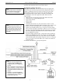
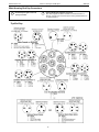
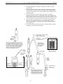
Connect the auxiliary sensors (up to 8 auxiliary sensors) to JT2, JT3, JT5,
and JT6 on the SBE 9plus top end cap. Each connector interfaces with up to
two auxiliary sensors. Connection of the auxiliary sensors to the 9plus
must correspond to the instrument configuration in the .xmlcon or .con file
(see Setup for Deployment).
SBE 9plus to Water Sampler
Note:
300 baud modem interfaces are
required in the 9plus and 11plus V2
Deck Unit for operation with a water
sampler. The interface, now standard
in both the Deck Unit and CTD,
was optional in Deck Units with
serial number 700 and lower and in
9plus CTDs with serial number 785
and lower.
•
•
•
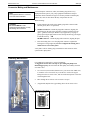
SBE 32 Carousel - Connect the 9plus 6-pin top center JT7 connector to
the 6-pin bulkhead connector at the bottom of the Carousel electronics
housing with the 6-pin to 6-pin jumper cable.
G.O. 1015 Rosette - Connect the 9plus 3-pin JT4 connector to the
Rosette. The G.O. 1015 has 2 polarity settings, normal and reverse, which
refer to the sea cable polarity. Most commonly, it is set to reverse,
especially when used with a MK III CTD. The 9plus can be used with the
G.O. 1015 in either setting by choosing the appropriate interface cable:
17196 for reverse or 17533 for normal. If you have only one interface
cable, the polarity setting of the G.O. 1015 can be changed to correspond
with your cable (see Application Note 35).
G.O. 1016 Rosette - Connect the 9plus 6-pin top center JT7 connector to
the Rosette.
Wiring System – Use with SBE 17plus V2 SEARAM
CAUTION:
The SEARAM has no clamp or voltage
drop circuitry to limit supply voltage to
the 9plus. Thus, the voltage supplied
by the SEARAM’s power supply is the
voltage supplied to the 9plus, which is
also the voltage supplied by the 9plus
to all its auxiliary sensors. Some
auxiliary sensors, such as WET Labs
ECO sensors, are limited to input
voltages less than 15 volts. Twelve
fully charged batteries in the SEARAM
supply the following voltage:
• NiMH or Ni-Cad - 14.4 volts
• Alkaline - 18 volts
Using alkaline batteries in the
SEARAM for 9plus deployments
including lower input voltage
sensors can damage the sensors.
Note:
300 baud modem interface is required
in the 9plus for operation with a water
sampler. The interface, now standard,
was optional in 9plus CTDs with serial
number 785 and lower.
SBE 9plus to SEARAM
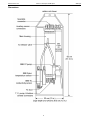
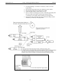
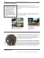
Connect the SBE 9plus 6-pin JT7 to the SEARAM 6-pin connector (clockwise
from the switch plunger) using the supplied cable.
SBE 9plus to Auxiliary Sensors
Connect the auxiliary sensors (up to 8 auxiliary sensors) to JT2, JT3, JT5,
and JT6 on the SBE 9plus top end cap. Each connector interfaces with up to
two auxiliary sensors. Connection of the auxiliary sensors to the 9plus
must correspond to the instrument configuration in the .xmlcon or .con file
(see Setup for Deployment).
SBE 9plus to Water Sampler
Connect the water sampler to the SEARAM, not to the SBE 9plus (see the
SEARAM manual).
21