1
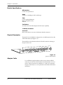
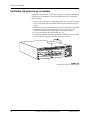
Quad Nx 56/64
Module
Part Number 1200184L1
USER MANUAL
61200.184L1-1A
November 1997
901 Explorer Boulevard
P.O. Box 140000
Huntsville, AL 35814-4000
(205) 963-8000
© 1997 ADTRAN, Inc.
All Rights Reserved.
Printed in U.S.A.
FEDERAL COMMUNICATIONS COMMISSION
RADIO FREQUENCY INTERFERENCE STATEMENT:
This equipment has been tested and found to comply with the limits for a Class A digital device, pursuant to Part 15
of the FCC Rules. These limits are designed to provide reasonable protection against harmful interference when the
equipment is operated in a commercial environment. This equipment generates, uses, and can radiate radio frequency
energy and, if not installed and used in accordance with the instruction manual, may cause harmful interference to
radio frequencies. Operation of this equipment in a residential area is likely to cause harmful interference in which
case the user will be required to correct the interference at his own expense.
Shielded cables must be used with this unit to ensure compliance with Class A FCC limits.
Change or modifications to this unit not expressly approved by the party responsible for compliance could void the user’s authority to operate the equipment.
Table of Contents
Chapter 1: Introduction ......................................................................................................................................
Quad nx 56/64 Module overview ......................................................................................................................
Features............................................................................................................................................................
Interfaces .........................................................................................................................................................
Module Specifications ...................................................................................................................................
DTE Interface....................................................................................................................................
Rates...................................................................................................................................................
Tests ...................................................................................................................................................
Test Pattern .......................................................................................................................................
1s Density Protection.......................................................................................................................
Connector..........................................................................................................................................
Physical Description ......................................................................................................................................
Adapter Cable.................................................................................................................................................
1
1
1
1
2
2
2
2
2
2
2
2
2
Chapter 2: Installation ........................................................................................................................................
Unpack and Inspect ..............................................................................................................................................
ADTRAN Shipments Include.......................................................................................................................
Customer Provides ........................................................................................................................................
Installing the Quad Nx 56/64 Module...............................................................................................................
Wiring .....................................................................................................................................................................
Power-Up Testing and Initialization ..................................................................................................................
3
3
3
3
4
5
5
Chapter 3: Operation ..........................................................................................................................................
Overview ................................................................................................................................................................
TERMINAL Menu Structure ...............................................................................................................................
Menu Description...........................................................................................................................................
Slt........................................................................................................................................................
Type ...................................................................................................................................................
Menu..................................................................................................................................................
Alarms ...............................................................................................................................................
Test.....................................................................................................................................................
State....................................................................................................................................................
Status .................................................................................................................................................
Hardware Revision..........................................................................................................................
Quad Nx 56/64 Module Menu Options .....................................................................................................
Quad Nx Info...........................................................................................................................................
Part Number.....................................................................................................................................
Serial Number ..................................................................................................................................
Quad Nx Alarms .....................................................................................................................................
SLIP....................................................................................................................................................
PLL.....................................................................................................................................................
ZERO .................................................................................................................................................
NO EXT CLK ....................................................................................................................................
DTE Status................................................................................................................................................
RTS .....................................................................................................................................................
CTS.....................................................................................................................................................
DTR ....................................................................................................................................................
DSR ....................................................................................................................................................
DCD ...................................................................................................................................................
RI ........................................................................................................................................................
TD.......................................................................................................................................................
RD ......................................................................................................................................................
Data Rate ..................................................................................................................................................
Inband.......................................................................................................................................................
ID........................................................................................................................................................
PASS ..................................................................................................................................................
CRC....................................................................................................................................................
TX .......................................................................................................................................................
7
7
7
8
8
8
9
9
9
9
9
9
10
10
10
10
10
10
10
10
11
11
11
11
11
11
11
11
11
11
11
11
11
11
11
12
61200.184L1-1
Quad Nx 56/64 Module User Manual
i
Table of Contents
RX.......................................................................................................................................................
PLL/Fifo...................................................................................................................................................
Lock....................................................................................................................................................
RXE ....................................................................................................................................................
RXF.....................................................................................................................................................
TXE.....................................................................................................................................................
TXF.....................................................................................................................................................
Configuration ..........................................................................................................................................
Name .................................................................................................................................................
Clk (+/-) (TX Clock Polarity) .........................................................................................................
Clk Srce (Clock Source)...................................................................................................................
Data (Data Format)..........................................................................................................................
CTS.....................................................................................................................................................
DCD ...................................................................................................................................................
DSR ....................................................................................................................................................
DTR ....................................................................................................................................................
0 Inh (Zero Inhibit) ..........................................................................................................................
Test ............................................................................................................................................................
Loopbk...............................................................................................................................................
Loopback Status ...............................................................................................................................
511 (511 Test Pattern) ......................................................................................................................
511 Result ..........................................................................................................................................
Inject (Inject Error) ...........................................................................................................................
511 Clr (Clear Results).....................................................................................................................
12
12
12
12
12
12
12
12
12
12
12
12
13
13
13
13
13
14
14
14
14
14
15
15
Appendix A: Quad Nx 56/64 Dial Plan Interface Configuration ...............................................................
Interface Configuration ........................................................................................................................................
Nx56/64 Option Module Interface Configuration....................................................................................
Nx56/64 Option Module (User Termination) ....................................................................................
Ports Available .................................................................................................................................
Number of Ports...............................................................................................................................
17
17
18
18
18
18
ii
Quad Nx 56/64 Module User Manual
61200.184L1-1
Chapter 1
Introduction
QUAD Nx 56/64 MODULE OVERVIEW
The Quad Nx (pronounced “N-by”) 56/64 Module provides four synchronous V.35 DTE ports, each of which can operate at any rate that is a
multiple of 56 or 64 kbps, up to 1.536 Mbps. The Quad Nx 56/64 Module
can be installed in any option slot of the ATLAS chassis.
Features
•
•
•
•
•
•
•
Each port operates using 1 to 24 DS0s
Includes an elastic store for absorption of rate variations
Any port can be used as a timing source for the entire system
Outputs a 50 percent duty-cycle output clock at all rates
Generates and responds to V.54 looping codes
Generates and checks 511 test patterns
Bidirectional loopbacks:
- Port (toward the network)
- DTE (toward the DTE)
Loopbacks can be invoked locally or remotely (V.54).
Interfaces
• CCITT V.35 electrical (differential)
• Connector: DB-37 (DB-37 to Dual Winchester V.35 connector adapter
cables are shipped with this module)
61200.184L1-1
Quad Nx56/64 Module User Manual
1
Chapter 1. Introduction
Module Specifications
DTE Interface
CCITT V.35 Synchronous
Rates
56 kbps to 1.536 Mbps in 56K or 64K steps
Tests
Local Loopback (Bilateral)
Remote Loopback (V.54)
Self Test
Test Pattern
511 with errored seconds display and error inject capability
1s Density Protection
Connector
DB-37 with cables to convert to Winchester female connectors
Physical Description
The Quad Nx 56/64 Module can plug into any available option slot in the
ATLAS 800 chassis (see Figure 1-1).
The module has an indication under each D-shell connector referring to
the port on the card.
Figure 1-1
Quad Nx 56/64 Module
Adapter Cable
Two ADTRAN-supplied adapter cables convert from the DB-37
connectors on the rear of the module to Dual Winchester V.35 connectors. These connectors are marked as 1/3 and 2/4 to represent
the port connected (1 or 3/2 or 4), based on which DB-37 the cable is
attached to.
2
Quad Nx56/64 Module User Manual
61200.184L1-1
Chapter 2
Installation
UNPACK AND INSPECT
Carefully inspect the option module for any shipping damage. If damage
is suspected, file a claim immediately with the carrier and then contact
ADTRAN Technical Support. (See the last page of this manual for information on contacting Technical Support.) If possible, keep the original
shipping container for use in shipping the option module back for repair
or for verification of damage during shipment.
ADTRAN Shipments Include
• The Quad Nx 56/64 Module
• The Quad Nx 56/64 Module User Manual (to be inserted into the appropriate section of the ATLAS 800 User Manual)
• Two DB-37 to dual V.35 Winchester adapter cables
Customer Provides
• DTE cables
61200.184L1-1
Quad Nx 56/64 Module User Manual
3
Chapter 2. Installation
INSTALLING THE QUAD NX 56/64 MODULE
Figure 2-1 is representative of the action required for proper placement of
the Quad Nx 56/64 Module. Perform the following steps to install the
option module:
1. Remove the cover plate (corresponding to the slot in which the Quad
Nx 56/64 Module will be installed) from the ATLAS 800 chassis rear
panel.
2. Slide the Quad Nx 56/64 Module into the ATLAS 800 chassis until the
module is positioned firmly against the front of the ATLAS unit.
3. Fasten the thumbscrews at both edges of the option module.
4. Connect the cables to the associated device (s).
5. Complete installation of remaining modules and Base Unit as specified
in the Installation chapter of the ATLAS 800 User Manual.
Figure 2-1
Installing the Quad Nx 56/64 Module
4
Quad Nx 56/64 Module User Manual
61200.184L1-1
Chapter 2. Installation
WIRING
Each port of the Quad Nx 56/64 Module has a V.35 Winchester-style
connection (via the supplied adapter cables) as defined in Table 2-A.
Table 2-A
V.35 Winchester Pin Connection
Pin
CCITT
A
B
C
D
E
F
H
J
L
N
R
T
V
X
P
S
Y
AA
U
W
NN
101
102
105
106
107
109
104
104
115
115
103
103
114
114
113
113
-
DESCRIPTION
Protective ground (PG)
Signal ground (SG)
Request to send (RTS) from DTE
Clear to send (CTS) to DTE
Data set ready (DSR) to DTE
Received line signal detector (DCD) to DTE
Data terminal ready (DTR) from DTE*
Ring indicator (RI)*
Local loopback (LL) from DTE*
Remote loopback (RL) from DTE*
Received data (RD-A) to DTE
Received data (RD-B) to DTE
RX clock (RC-A) to DTE
RX clock (RC-B) to DTE
Transmitted data (TD-A) from DTE
Transmitted data (TD-B) from DTE
TX clock (TC-A) to DTE
TX clock (TC-B) to DTE
External TX clock (ETC-A) from DTE
External TX clock (ETC-B) from DTE
Test mode (TM) to DTE
* Ignored by Quad Nx 56/64 Module
POWER-UP TESTING AND INITIALIZATION
The Quad Nx 56/64 Module executes a self test during the power-up
sequence, as described in the ATLAS 800 User Manual. Upon power-up,
any previously configured setting for the Quad Nx 56/64 Module is automatically restored.
When the self test is completed and the configuration is successfully
restored, the LED labeled OK in the Module group on the front panel
turns On. If any alarms are detected during operation, the red LED
labeled ALARM in the Module group on the front panel turns On.
If the power-up self test is not successful, refer to the Troubleshooting section of the ATLAS 800 User Manual to diagnose and correct the problem.
Return to Chapter 2 (Installation) of the ATLAS 800 User Manual to continue system set-up.
61200.184L1-1
Quad Nx 56/64 Module User Manual
5
Chapter 2. Installation
6
Quad Nx 56/64 Module User Manual
61200.184L1-1
Chapter 3
Operation
OVERVIEW
The Quad Nx 56/64 Module can be configured and controlled from a
variety of sources, including:
• The ATLAS 800 Front Panel, providing minimal configuration and status support
• The terminal menus, allowing detailed configuration, status, and diagnostics
• SNMP, used primarily for reporting alarm conditions and system status
The terminal menu is accessed using either a VT 100 Terminal attached to
the ATLAS 800 Base Unit’s control port, or through a Telnet session,
established through the Base Unit’s Ethernet port. Detailed instructions
on the operation of each of the supported management approaches are
presented in the ATLAS 800 User Manual.
In order to edit items in the terminal menus, you must have the appropriate password level. Each menu description in this section indicates the required password
level required for write and read access. See the section Access Passwords in the
ATLAS 800 User Manual for detailed information on working with passwords.
Security level 1 users can view and edit every available field. Security level 5 users
can view any field but cannot edit.
The remainder of this section describes the menu items presented when
managing the Quad Nx 56/64 Module via the terminal menus.
TERMINAL MENU STRUCTURE
The ATLAS 800 uses a form of hierarchical menus to access all features.
The topmost menu level leads to submenus which are grouped by functionality. All menu items display in the terminal window.
Refer to the ATLAS 800 User Manual for detailed instructions on how to navigate through the terminal menu.
61200.184L1-1
Quad Nx 56/64 Module User Manual
7
Chapter 3. Operation
The ATLAS 800 System Controller automatically detects the presence of
the Quad Nx 56/64 Module when it is installed in the system. To see the
menus for the Quad Nx 56/64 Module via the terminal menu, use the
arrow keys to scroll to the Modules menu and press Enter to access the
module choices. Figure 3-1 shows the Modules menu. The following sections describe all the menu options.
Figure 3-1
Modules Menu
Menu Description
Slt
Read security: 5
Displays the number of all the available slots in the ATLAS 800 chassis.
Slot 0 refers to the ATLAS 800 base unit. This field is read-only.
Type
Write security: 3; Read security: 5
Displays the type of module actually installed in the slot or the type of
module you plan to install in the slot. If a Quad Nx 56/64 Module is
installed, the Type field will automatically default to V35Nx-4 (the Quad
Nx 56/64 Module). You can use this field to pre-configure a system
before actually installing modules by simply specifying the module that
you want to install in each slot.
If you install a module in a slot, then want to install a different type of module in
the slot, you must set this field to Empty before selecting another module type.
If a module is installed, the module type will automatically display the name of the
installed module, and cannot be set to any other option.
8
Quad Nx 56/64 Module User Manual
61200.184L1-1
Chapter 3. Operation
Menu
Selecting this item displays additional status and configuration menus
about the selected module. (To access the submenus for this item, use the
arrow keys to scroll to the Menu column for the module you want to edit,
and press Enter.) For detailed information on each submenu item, see the
section Quad Nx 56/64 Module Menu Options on page 10.
Alarms
Read security: 5
This field displays whether there is an alarm condition on the Quad Nx
56/64 Module. Press Enter in this field to activate the Alarm menu.
Test
Read security: 5
This field displays whether the Quad Nx 56/64 Module is executing a
test. Press Enter in this field to activate the Test menu.
State
Write security: 3; Read security: 5
Even though a module is physically installed, it must be marked Online
for it to be considered an available resource. This parameter allows an
installed module to be marked Offline, which may be useful in system
troubleshooting.
Status
Read security: 5
This is a read-only field presenting status information on the Quad Nx
56/64 Module. The following messages may display:
Online:
No Response:
Empty:
Offline
Offline/
No Response:
The module is enabled, and is responding to the System Controller’s status polls. This is the normal
response of the system.
The module is enabled, but is not responding to the
System Controller’s status polls. This response indicates either a problem in the system or that the module is not installed.
The System Controller has not detected the presence
of a module in the slot, nor has a module been manually enabled for this option slot.
The module is installed, but has been taken Offline
by a user. The module is still responding to controller
polls.
The module is installed, but has been taken Offline
by a user. The module is not responding to polls.
Hardware Revision
Read security: 5
This is a read-only field that displays the hardware revision of the Quad
Nx 56/64 Module.
61200.184L1-1
Quad Nx 56/64 Module User Manual
9
Chapter 3. Operation
Quad Nx 56/64 Module Menu Options
Figure 3-2 shows the menu options available for the Quad Nx 56/64
Module. The following sections describe these options.
Quad Nx Info
Figure 3-2
Quad Nx 56/64 Module Menu Options
Read security: 5
The Quad Nx 56/64 Info submenu indicates the status of the module.
Part Number
Displays the part number of the module. This field is read-only.
Serial Number
Displays the Quad Nx 56/64 Module’s serial number. This field is readonly.
Quad Nx Alarms
Read security: 5
This option displays any active alarms. These fields are read-only.
SLIP
A rate mismatch exists between the DTE clock and the network-side clock
(as set by DS0 assignment).
PLL
The Nx port is not able to lock onto the clock provided by the network
interface.
ZERO
The DTE is sending an excessive number of consecutive zeroes to the network interface.
10
Quad Nx 56/64 Module User Manual
61200.184L1-1
Chapter 3. Operation
NO EXT CLK
The DTE is not providing an external transmit clock (only if the V.35 Nx
port is configured to get transmit clock from the DTE.)
DTE Status
Read security: 5
Shows the status of key DTE interface signals. The following signals are
monitored (these options are read-only):
RTS
Request To Send from DTE
CTS
Clear To Send to DTE
DTR
Data Terminal Ready from DTE
DSR
Data Set Ready to DTE
DCD
Data Carrier Detect to DTE
RI
Ring Indicate to DTE
TD
Transmit Data from the DTE
RD
Receive Data toward the DTE
Data Rate
Read security: 5
Displays the data rate at which each Nx port is currently operating. A
port’s data rate is determined by the number of DS0s assigned to it and the
rate per DS0 associated with the active maps.
Inband
Read security: 5
ID
Correct Unit ID
PASS
Correct Password
CRC
Correct CRC
61200.184L1-1
Quad Nx 56/64 Module User Manual
11
Chapter 3. Operation
TX
Active Transmit
RX
Active Receive Data
PLL/Fifo
Read security: 5
Lock
Phase Lock Loop is locked
RXE
Receive data FIFO Empty
RXF
Receive Data FIFO Full
TXE
Transmit Data FIFO Empty
TXF
Transmit Data FIFO Full
Configuration
The CONFIG submenu configures the Quad Nx 56/64 Module.
Name
Write security: 3; Read security: 5
Allows you to enter a descriptive alpha-numeric name for each port.
Clk (+/-) (TX Clock Polarity)
Write security: 3; Read security: 5
Controls the clock used by the Quad Nx 56/64 Module to accept the transmit (TX) data from the DTE. This is usually set to Normal. If the interface
cable is long, causing a phase shift in the data, the clock can be set to Inverted. This switches the phase of the clock, which should compensate for
a long cable.
Clk Srce (Clock Source)
Write security: 3; Read security: 5
Selects the source for the DTE transmit clock, either Internal or DTE.
Data (Data Format)
Write security: 3; Read security: 5
Used to control the inverting of the DTE data. This inversion can be useful
when operating with a high-level data link control (HDLC) protocol (often
used as a means to ensure 1s density). Select either Normal or Inverted.
12
Quad Nx 56/64 Module User Manual
61200.184L1-1
Chapter 3. Operation
CTS
Write security: 3; Read security: 5
Clear to Send. Used to control characteristics of CTS (see Table 3-A).
Choose from Normal or Forced On.
DCD
Write security: 3; Read security: 5
Data Carrier Detect. Indicates to the DTE when a valid signal is being received at the Network Interface (see Table 3-A). Choose from Normal or
Forced On.
DSR
Write security: 3; Read security: 5
Data Set Ready. This signal indicates to the DTE when the DCE is turned
On and ready for operation (see Table 3-A). Choose from Normal or
Forced On.
DTR
Write security: 3; Read security: 5
Data Terminal Ready. This parameter determines whether the ATLAS 800
treats a connection as permanent (DTR=Ignore) or to connect only when
DTR is active (DTR=Connect On DTR). Select either Ignore or Connect on
DTR.
0 Inh (Zero Inhibit)
Write security: 3; Read security: 5
When the port detects an uninterrupted string of 0s being transmitted for
more than one second, setting this parameter to ON will cause the ATLAS
800 to send 1s toward the network.
Table 3-A
Normal Mode Operation
(conditions which cause the port control signal to be deactivated)
SIGNAL
RTS
V.54 LOOPBACK
CTS
DCD
DSR
Follows
—
—
Off
—
Off
511 TEST ON SELF TEST ACTIVE
Off
—
Off
Off
Off
Off
NETWORK
TEST ACTIVE
Off
Off
Off
NO DS0
MAPPED
Off
Off
Off
NETWORK
ALARM
Off
Off
—
— = Do not care
Force On = On under all conditions
61200.184L1-1
Quad Nx 56/64 Module User Manual
13
Chapter 3. Operation
Test
This menu item is used to activate testing of specific data ports. It also controls the activation of loopbacks and the initiation of data test patterns.
Test results are displayed on the ATLAS 800 front panel.
The execution of Port Tests disrupts normal data flow in the port being tested.
Loopbk
Write security: 4; Read security: 5
Controls the activation and deactivation of loopbacks.
The loop is deactivated.
The Nx port activates both a local loopback (back toward the DTE) and a port loopback when invoked.
Remote Loopback The remote loopback causes a V.54 loopback code to
be sent to the far end. If the device at the far end supports V.54, the device activates a loopback on detection of the V.54 code.
No Loopback
Local Loopback
Loopback Status
Read security: 5
This read-only option indicates a port’s current loopback status by displaying any of the following status messages:
•
•
•
•
•
•
•
No loopback active
Looping up remote unit
Remote unit looped back
Looping down remote unit
Remote loopup failed
Port looped from remote source
Port loopback active
511 (511 Test Pattern)
Write security: 4; Read security: 5
Controls the activation of the 511 test pattern generator and detector.
Off
On
Turns off the 511 test pattern generator and detector.
Turns on the 511 test pattern generator and detector.
511 Result
Read security: 5
Displays the results of the 511 test. This option is read-only.The results are
in the form of the number of errored seconds.
Sync
ES
14
Y (yes), N (no)
Errored seconds. Indicates the number of seconds (after
pattern sync) that have contained at least one error.
Quad Nx 56/64 Module User Manual
61200.184L1-1
Chapter 3. Operation
Inject (Inject Error)
Write security: 4; Read security: 5
Injects a 511 pattern error.
511 Clr (Clear Results)
Write security: 4; Read security: 5
Clears test results for the selected port.
61200.184L1-1
Quad Nx 56/64 Module User Manual
15
Chapter 3. Operation
16
Quad Nx 56/64 Module User Manual
61200.184L1-1
Appendix A
Quad Nx 56/64 Dial Plan Interface Configuration
INTERFACE CONFIGURATION
The Interface Configuration option for the Dial Plan menu sets configuration parameters for the end point. These parameters will vary by the type
of port selected. The following section describes the configuration
options available for the Quad Nx 56/64 Module. The Dial Plan menus
are only accessible when using terminal mode. To access these options,
select Dial Plan from the top level menu.
Figure A-1
Dial Plan Menus
61200.184L1-1
Quad Nx 56/64 Module User Manual
17
Appendix A: Nx 56/64 Dial Plan Interface Configuration
Nx56/64 Option Module Interface Configuration
This section describes the User Termination configuration settings for the
Quad Nx56/64 Module when using the Dial Plan menus.
The Nx56/64 can only serve as a User termination end point.
Nx56/64 Option Module (User Termination)
When you are working in the User Termination section of the Dial Plan
menu, the Slot is defined as a Nx56/64 module, the following configuration options are available:
Ports Available
Indicates which of the four ports of the Quad Nx56/64 module have
already been defined either in another switched end point (indicated by
“s”) or in a Dedicated Map (indicated by “n”). This field is read-only.
Number of Ports
Defines to ATLAS how many of the ports could be used to answer calls to
the number(s) defined in the Accept Call list. You can enter numbers 1
through 4. The ports are contiguous beginning with the Port number
select and the number of ports.
Example: If the port selected (as a part of Slot/Port selection) is 2, and the
number of ports selected here was 2, then ports 2 and 3 would be enabled
to receive calls to the numbers listed under the Incoming Call Accept list.
18
Quad Nx 56/64 Module User Manual
61200.184L1-1
Index
Numerics
I
511
inband 11
initialization 5
inject error 15
installation 3
installing the module 4
interface configuration 17
interfaces 1
pattern 14
test results
14
A
adapter cable
alarm
PLL 10
status 10
zero 10
alarms 9
2
L
local loopback 14
loopback 14
local 14
none 14
remote 14
status 14
loopbk 14
C
clear results 15
clear to send 13
clock source 12
configuration 12
connection
pins 5
CTS 11, 13
M
menu
description 8
options 10
Quad Nx 56/64 10
structure 7
submenu items 10
D
data carrier detect 13
data format 12
data rate 11
data set ready 13
DCD 11, 13
description
physical 2
dial plan configuration
DSR 11, 13
DTE status 11
DTR 11
F
features 1
61200.184L1-1
17
name 12
no ext clock 11
no loopback 14
O
operation 7
overview
overview 1
7
P
H
hardware revision
N
9
physical description
pin connections 5
PLL alarm 10
PLL/Fifo 12
power-up testing 5
Quad Nx 56/64 Module User Manual
2
19
Index
Q
Quad Nx 56/64
features 1
installing 4
interfaces 1
menu options 10
overview 1
physical description
specifications 2
Quad Nx alarms 10
Quad Nx info 10
2
R
RD 11
remote loopback
RI 11
RTS 11
14
S
self test 14
slip 10
specifications
state 9
status 9
alarm 10
2
T
TD 11
terminal menu structure
test 9, 14
testing 5
TX clock polarity 12
type 8
7
W
wiring
5
Z
zero alarm 10
zero inhibit 13
20
Quad Nx 56/64 Module User Manual
61200.184L1-1
Product Support Information
Presales Inquiries and Applications Support
Please contact your local distributor, ADTRAN Applications Engineering, or
ADTRAN Sales:
Applications Engineering
Sales
(800) 615-1176
(800) 827-0807
Post-Sale Support
Please contact your ADTRAN account representative first. If your ADTRAN account representative cannot help, please contact ADTRAN Technical Support and have the unit serial number available.
Technical Support
(888) 4ADTRAN
Repair and Return
If ADTRAN Technical Support determines that a repair is needed, Technical Support will coordinate with the Return Material Authorization (RMA) department to issue an RMA number. For information regarding equipment currently in house or possible fees associated with repair, contact
RMA directly at the following number:
RMA Department
(205) 963-8722
Identify the RMA number clearly on the package (below address), and return to the following address:
ADTRAN, Inc.
RMA Department
901 Explorer Boulevard
Huntsville, Alabama 35806
RMA # _____________