1
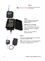
X Series User's Manual (For X7D & X80) Version 1.6.6 8157 U.S Highway 50 – Athens, Ohio 45701 – www.buckeyecam.com WARRANTY REGISTRATION ATSI warrants Products (BuckEye CamTM ) sold by it and guarantees to correct, by repair or replacement at our option, any defects of material and workmanship which develop under normal and proper use within six (6) months from the date of the original purchase when inspection proves the fault to be of manufacturing. Circuit board components only receive a twelve (12) month warranty. All such Products must be returned to our service center, transportation charges prepaid. This warranty does not apply to any of our Products which have been repaired or altered by unauthorized persons or service centers in any way so as, in our judgment, to injure their stability or reliability, or which have been subject to misuse, negligence, or accident or whichh have had their serial number altered, effaced or removed. We will not assume any expense or liability for repairs made by other parties without our written consent. ATSI is not responsible for damage to any associated equipment or apparatus, nor shall we be held liable for loss of profit or other special damages. There is no other guarantee or warranty except as herein stated. The Buyer, his employees, or others assumes all risks and liabilities for the operation, the use and the misuse of the product described herein and agree to defend and to save the seller harmless from any and all claims arising from any cause whatsoever, including seller’s negligence for personal injury incurred in connection with the use of the said product. ATSI reserves the right to discontinue models at any time or change specifications, price or design without notice and without incurring any obligation. The express warranties are in lieu of all other warranties, guarantees, promises, affirmations, or representations, express or implied which would be deemed applicable to the goods sold hereunder. No express warranties and no implied warranties, whether of merchantability, fitness for any particular use or purpose, against infringement, or otherwise (except as to title) other than those expressly set forth herein, shall apply. For service or repair, contact ATSI/Buckeye Cam at: ATSI 8157 US Hwy 50 • Athens, OH 45701 (866) 325-8172 • (740) 592-2874 Fax (740) 594-2875 [email protected] Table of Contents - X Series User's Manual 1. Warnings...................................................................................2 2. Overview...................................................................................3 2.1 PC Base Overview..................................................................4 2.2 Camera Base Overview..........................................................5 2.3 CellBase Overview..................................................................6 2.4 NetBase Overview...................................................................7 3. X Series PC Base......................................................................8 3.1 Getting Started........................................................................8 4. Camera Base..........................................................................12 4.1 Setting up other cameras to report to the camera base.........12 5. CellBase..................................................................................14 5.1 CellBase Unit Connections and Controls..............................15 5.2 CellBase Setup and Operation.............................................17 5.3 Configuring X Series Network Manager for CellBase............18 5.4 Running the CellBase............................................................19 6. NetBase...................................................................................20 6.1 NetBase Unit Connections and Controls..............................21 6.2 Powering the NetBase..........................................................22 6.3 Configuring X Series Network Manager for NetBase.............22 5.4 Running the NetBase............................................................24 7. Standalone Mode....................................................................25 7.1 Viewing pictures in Standalone Mode....................................26 8. Camera Operation..................................................................28 8.1 Camera Specifications Table.................................................30 9. Camera Installation..................................................................32 10. Antennas...............................................................................34 11. Using Cameras as Repeaters...............................................36 11.1 Setting up a Repeater Network...........................................37 12. Software, Camera Firmware & Support.................................38 12.1 Software & Firmware Tutorials.............................................38 12.2 Technical Support................................................................38 13. Setting Up X Series Network Manager to E-mail Pictures....39 14. Setting Up LiveCam...............................................................42 15. Contact Us ............................................................................43 1. Warnings Contains FCC ID:MCQ-XBEE09P The enclosed device complies with Part 15 of the FCC Rules. Operation is subject to the following two conditions: (i.) this device may not cause harmful interference and (ii.) this device must accept any interference received, including interference that may cause undesired operation. If the camera is used with any antenna other than the portable antenna supplied with the X Series Camera Unit or PCBase Unit, the system may not comply with the FCC regulation Part 15.247, Operation within the license-free band 902 – 928 MHz. Contact manufacturer regarding use of optional high-gain antennas with the X Series wireless camera system. WARNING: To satisfy FCC RF exposure requirements for mobile transmitting devices, a separation distance of 20 cm or more should be maintained between the antenna of this device and persons during device operation. To ensure compliance, operations at closer than this distance are not recommended. The antenna used for this transmitter must not be co-located in conjunction with any other antenna or transmitter. 2. Overview The X Series Motion Activated Wireless Camera System consists of one or more wireless cameras and a base. The cameras are powered with rechargeable lead acid batteries and can take thousands of pictures on a single charge. Optional solar panel chargers are also available to extend battery life indefinitely. When a camera detects motion, a picture or video is immediately taken and transmitted to the base. The cameras can be up to one mile, line of sight (X7D) or up to two miles (X80) from the base using standard antennas. This distance can be increased to several miles using high gain antennas or by repeating through other cameras. Several different options are available to allow the pictures received at the base to be viewed from anywhere in the world using an Internet connected computer or smart phone. Three different types of bases are available : PC Base, Camera Base, CellBase, and NetBase. The operation of each type of base is described in detail in the appropriate section of this manual. A general overview of the four types is given here. Please Note: The X7D and X80 Cameras are not compatible. X7D cameras and X7D PCBase hardware is upgradeable to X80 hardware. Contact BuckEye Cam for more information. 3 X Series – User's Manual v1.6.6 2.1 PC Base Overview Connects View to a personal computer with a USB connection. pictures from up to 255 remote cameras on your computer. Automatically email pictures or upload to the Livecam Web-site if an Internet connection is available. Transmission distance can be up to 1 mile X7D (line of sight) / Up to 2 miles with the X80 Transmission distance can be increased to several miles with high gain antennas or by repeating through other cameras. NO monthly fees. Cellular service is NOT required. Best choice when there is a personal computer within one mile (line of sight) of at least one camera. 4 X Series – User's Manual v1.6.6 2.2 Camera Base Overview Camera acts as a base. Can also take pictures and video just like a normal camera. Can receive pictures or video from up to 255 remote cameras. Pictures are stored on an SD card inside the Camera Base. Transmission distance can be up to 1 mile (line of sight) with the X7D / Up to 2 miles with the X80. Transmission distance can be increased to several miles with high gain antennas or by repeating through other cameras. NO monthly fees. Cellular service is NOT required. Best choice when a personal computer is NOT available within one mile, line of sight (X7D) or up to two miles (X80)of at least one camera and it is possible to visit the Camera Base to retrieve the pictures. 5 X Series – User's Manual v1.6.6 2.3 CellBase Overview Can receive pictures or video from up to 255 remote cameras. A cellular Internet connection is used to connect to a personal computer running the X Series software. Works Only with most major cellular carriers. one cellular data plan is required for up to 255 cameras. View pictures or video, and control your cameras from anywhere in the world using an Internet connected computer. Best choice when a personal computer is NOT available within one mile, line of sight(X7D) or up to two miles (X80) of at least one camera and it is NOT possible to visit the cameras to retrieve pictures. 6 X Series – User's Manual v1.6.6 2.4 NetBase Overview Can receive pictures or video from up to 255 remote cameras. A network / Internet connection is used to connect to a personal computer running the X Series software. Best choice when a network connection and power is available within one mile, line of sight(X7D) or up to two miles (X80) of at least one camera but the computer receiving pictures and controlling cameras must be located at a different site. Remote Camera 1 Computer connected to the Network Network 7 Remote Camera 2 X Series – User's Manual v1.6.6 3. X Series PC Base Before installing your cameras in the field location you will need to register them to the PC Base. The registration process will assign each camera a specific number and channel so that it will only communicate with the PC Base that it is registered to. Follow the steps in the Getting Started section to complete the registration process. 3.1 Getting Started Step 1 Install the X Series software and drivers using the supplied installation disk. The software may also be downloaded at: www.buckeyecam.com Step 2 Attach antenna to PC Base Step 3 Connect the PC Base to the computer USB port using the supplied USB cable. 8 X Series – User's Manual v1.6.6 Step 4 Connect the antenna to the camera. Step 5 Install a UB1270 type sealed lead acid battery into the battery pack. (Battery not included). The red wire goes to the ( + ) battery terminal and the black wire goes to the ( - ) battery terminal. Note : Use only UB1270 or equivalent battery. Step 6 Connect the battery pack to the camera using the supplied cable. to 9 Note: The female end of the cable connects the camera. The male end of the cable connects to the battery pack. X Series – User's Manual v1.6.6 Step 7 Open the camera enclosure and wait for this message to appear on the display. Step 8 Click on the X Series shortcut to start the software and click on Connect to Base. Step 9 Click on the Add Camera button to register the camera to the PCBase. Step 10 Click OK to confirm registration. Step 11 Click on the Camera Settings button to change the settings for the camera. If you have more than one camera, repeat steps 4 through 10 for each camera. 10 X Series – User's Manual v1.6.6 Note: One of the camera settings is a checkbox labeled Visible LED on trigger. If this box is checked, a visible red LED will turn on every time the motion detector is activated. This feature is very useful when installing a camera. It will allow you to do a "walk test" to verify that the camera is pointed properly for the intended target area (see the Camera Installation section). You may un-check this box once the camera is installed if camera concealment is important. Once all of your cameras are registered, it is highly recommended that you spend some time familiarizing yourself with the operation of the cameras and software before they are installed in the field. Refer to the Camera Installation section for instructions on how to install your cameras in the field. 11 X Series – User's Manual v1.6.6 4. Camera Base Using a camera as the base for a wireless camera system is the best way to utilize multiple cameras on your property when a computer is not available to run a PCBase. Follow these steps to set up multiple X Series cameras in wireless mode to report all pictures to a designated camera. Using a camera as a base allows you to retrieve pictures from all registered cameras without visiting each camera location to check SD cards, hence leaving your monitored areas virtually un-disturbed. 1. Designate a single camera to serve as the wireless system base. 2. Open the camera enclosure and press the ‘Next’ button until you see the ‘MODE’ command appear on the camera display, then press enter. 3. Press the ‘Next’ button until the ‘BASE’ prompt appears, then click enter. Your X Series camera is now enabled to serve as the base for other X Series cameras within range that you will set up to operate in wireless mode. (see step 4 - 6 for instructions on setting up other cameras in wireless mode to report to the camera base.) 4.1 Setting up other cameras to report to the camera base 1. Open the camera enclosure that you wish to set up in wireless mode to transmit to the base . Press the ‘Next’ button until you see the ‘MODE’ command appear, then click enter. 2. In the ‘MODE’ menu, click the ‘Next’ button until you see the ‘Wireless’ prompt appear, then click Enter. The camera will re-power itself and is ready to be added to the wireless camera base. Camera Base (Continued) 12 X Series – User's Manual v1.6.6 3. Each camera that is set up in wireless mode will need to be ‘added’ at the base camera. To add a camera press the ‘Next’ button on the base camera until the ‘ADD CAMERA’ prompt appears, then press next. Remember that this will need to be done for each camera that you want to transmit pictures to the camera base. 4. Cameras can be set up to transmit directly to base (if within range of the camera base) OR if you have cameras that cannot communicate directly to the base camera, they can be routed through another camera within range that reports to the base directly. To use the ‘repeater’ function through another camera to the base, press the ‘Next’ button until the route prompt appears, then press the enter button. The camera will search for other available cameras within range and will display cameras within range that can be selected. NOTE: We recommend that you make every effort to avoid routing cameras through other cameras in order to optimize battery life. At times, terrain, distance from camera to base and the presence of heavy pine trees will not allow you to achieve a direct signal to base. Higher gain antennas are available that could help you improve signal quality. For information about equipment upgrades, visit: www.buckeyecam.com 13 X Series – User's Manual v1.6.6 5. CellBase The X Series Cellbase provides an easy way to remotely operate your cameras. Unlike with the PCBase System where the cameras need to be within 1-2 miles (depending on model) from the computer running the X Series Network Manager, the CellBase allows the cameras to be placed hundreds of miles away. Operation of the CellBase is illustrated in the picture below. When the CellBase unit is turned on, it searches and then registers itself on a compatible cellular network. After the CellBase is connected to the Internet through a cellular network, a computer with an active Internet connection running the Base Software can connect to that CellBase to control and download pictures from the cameras. NOTE: Just like with a PCBase, pictures are downloaded directly to the computer. If the computer is not running the X Series Network Manager, is turned off, or is not connected to the Internet, pictures are buffered on the camera(s) until the camera(s) can “talk” to the X Series Network Manager. With the CellBase multiple cameras share one single cellular connection. Only one “cellular data plan” is required to operate up to 255 cameras. Internet Service Provider Internet Remote Camera 1 Computer with Internet Connection Cell Tower (Cellular Connection Provider) Remote Camera 2 As an option, the CellBase unit has a USB port that can be used to setup the cameras in the field. When a USB connection is used, the CellBase will operate just like a regular PCBase modem. This configuration does not require a cellular connection to be active for the system to operate. 14 X Series – User's Manual v1.6.6 5.1 CellBase Unit Connections and Controls The following illustration shows the external connections on the CellBase. Antenna Connector (Cellular Side) Antenna Connector (Camera Side) 12V Power USB Input Connector Antenna Connector (Cellular Side) – connect a cellular antenna to this connector. The cellular antenna has an N-male connector. If a directional antenna is used it should be pointed toward a cell tower. Protective Cap Antenna Connector (Camera Side) – connect an antenna that should be used to communicate with cameras. If a directional antenna is used, it should be pointed toward the cameras. USB Connector – Allows the user to connect to the CellBase unit directly though a USB cable. It can be used to set the camera system and register cameras in the field where an Internet connection is not available on the computer. 15 X Series – User's Manual v1.6.6 Protective Cap – The cap is used to protect the USB connector. Make sure the cap is properly installed and tightened to ensure a good watertight seal and protect the USB connector from the outdoor elements. 12V Power Input – Use the provided power cable to connect to a 12V battery or use the provided wall adapter with the adapter pigtail to power the CellBase. Note: the wall adapter configuration is for indoor use only! The following illustration shows the controls inside the CellBase. Reserved On/Off Switch Activity Cellular Network USB Connected On/Off Switch – This switch is used to turn the CellBase unit on. Activity – Indicates the current state of CellBase. When the indicator is gradually turning on and off every 3 seconds (“snoozing” or “snoring”), the CellBase is waiting for a connection from the X Series Network Manager. When flashing twice per second, the X Series Network Manager is connected to the CellBase. Cellular Network – Indicates the connection to the cellular network. When the indicator is OFF, the CellBase is searching or attempting to connect to the cellular provider. When the indicator is ON, the CellBase is connected to the network and is ready to communicate with the X Series Network Manager. USB Connected – When lit, indicates that the USB cable is connected and the X Series Network Manager can communicate in a tethered mode. Reserved – Reserved for future use. 16 X Series – User's Manual v1.6.6 5.2 CellBase Setup and Operation Powering the CellBase The X SeriesCellBase requires a 12V power source. The CellBase is supplied with a wall adapter and adapter pigtail for indoor applications AC power is available. For applications where AC power is not available, a 12V Lead Acid battery may be used. Duralast 27DP-DL marine Battery or equivalent is recommended. To connect the battery use the battery hookup cable supplied with the CellBase system. Make sure the cable terminals are securely connected to the battery terminals and a 4A fuse is installed in the cable. The connection diagram is shown below. NOTE: Before connecting or disconnecting the battery from the CellBase unit make sure the CellBase power switch is turned off. If more than one battery needs to be connected to increase the battery run time, the batteries should be connected in “parallel” (i.e. positive “+” of one battery connected to positive “+” of the next, negative of one battery connected to negative “-”of the next, and etc.). See illustration below. If you are not sure how to connect the batteries,contact a qualified electrician to have the CellBase connected to the batteries. 12V 27DP-DL 12V 12V 12V 4A fuse Wiring diagram for parallel connection of batteries. Connect to CellBase unit Single battery connection diagram. 17 X Series – User's Manual v1.6.6 5.3 Configuring X Series Network Manager for CellBase NOTE: In order to be able to communicate with a CellBase unit, make sure you are running X Series X Series Network Manager version 1.13 or higher. Each CellBase unit is shipped with a unique CellBase Information Sheet that contains information required to setup the X Series Network Manager. To setup the X Series Network Manager to communicate with a CellBase unit, click button in the software. This will open a PCBase Settings dialog window. In order to “tell” the X Series Network Manager to connect to a CellBase modem, make sure the Connect to CellBase modem box on the General tab is checked. If a regular PCBase modem is used, this box must be unchecked. In the CellBase tab, enter the IP Address/Domain Name from the CellBase Information Sheet into the CellBase Host Name/IP Address box. If an IP Address is provided, make sure it is entered as shown on the information sheet with dots (periods) and without spaces. Check for presence of connection with CellBase option tells the software how often to check for presence of an active connection with the CellBase unit. The connection may be dropped due to temporary loss of the Internet connection at the computer or a temporary drop of the cellular connection at the CellBase unit. To check for connection the software requests the battery level at the CellBase unit. If a response is not received within a reasonable period of time, the software will try to reestablish a connection with the CellBase unit. This option also determines how often the battery level at CellBase should be checked. 18 X Series – User's Manual v1.6.6 If connection with CellBase is lost, attempt reconnecting option tells the software how often to attempt a new connection when the previous connection with CellBase is lost. Setting this option to a smaller value will result in a faster recovery from a lost connection. Click the OK button to apply the settings and close the X Series Network Manager Settings window. 5.4 Running the CellBase Once the X Series Network Manager is configured to run with the CellBase, all the user needs to do is to click the Start PCBase button in the software. The software will initiate a connection with the CellBase and prompt the user for an Authentication Code. The Authentication Code is provided on the CellBase Information Sheet. Once the correct Authentication Code is entered the software would complete the connection with the CellBase unit. If there are cameras registered in the X Series Network Manager, the corresponding panels would appear. If no cameras are registered new cameras can be registered by clicking the Add Camera button in the software. Once the connection is established the operation is very similar to the one for PCBase. •When the X Series Network Manager is running with the CellBase, additional information is displayed in the status bar in the bottom of the X Series Network Manager window. •This field shows the status of the connection to the CellBase. When Online is displayed, the connection to the CellBase is active. When Offline is displayed, the software detected a connection drop and attempting to reconnect to the CellBase. •To get the actual voltage reading of the base battery place the mouse cursor over the 'battery icon at the bottom of the X Series Network Manager and pause for a few seconds. A hint box will appear showing the battery level in percentage points (%) and volts (V). •Cellular signal strength at the CellBase. More bars would indicate a faster connection to the CellBase and thus would result in faster picture transmission from cameras. 19 X Series – User's Manual v1.6.6 6. NetBase Similar to the CellBase, the X Series NetBase provides an easy way to remotely operate your cameras. The NetBase has an Ethernet port (RJ45) and requires a wired network connection to be available at the NetBase installation site. When the NetBase is turned on, it registers with the DHCP server and obtains an IP address. After the IP address is obtained, a computer running the X Series Network Manager can connect to the NetBase to control and download pictures from the cameras. NOTE: Just like with a PCBase, pictures are downloaded directly to the computer. If the computer is not running the X-Series Network Manager, is turned off, or is not connected to the Network, pictures are buffered on the camera(s) until the camera(s) can “talk” to the X-Series Network Manager. Remote Camera 1 Computer connected to the Network Network Remote Camera 2 As an option, the NetBase unit has a USB port that can be used to setup the cameras in the field. When a USB connection is used, the NetBase will operate just like a regular PCBase modem. This configuration does not require a network connection for the system to operate. 20 X Series – User's Manual v1.6.6 6.1 NetBase Unit Connections and Controls The following illustration shows the external connections on the Net Base. Antenna Connector (Camera Side) 12V Power USB Input Connector Antenna Connector (Camera Side) – connect an antenna that should be used to communicate with cameras. If a directional antenna is used, it should be pointed toward the cameras. Protective Cap USB Connector – Allows the user to connect to the NetBase unit directly though a USB cable. Protective Cap – The cap is used to protect the USB connector. Make sure the cap is properly installed and tightened to ensure a good watertight seal and protect the USB connector from the outdoor elements. 12V Power Input – Use the provided power cable to connect to a 12V 21 X Series – User's Manual v1.6.6 battery or use the provided wall adapter with the adapter pigtail to power the CellBase. Note: the wall adapter configuration is for indoor use only! The following illustration shows the controls inside the NetBase. Reserved On/Off Switch Activity USB Connected On/Off Switch – This switch is used to turn the CellBase unit on. Activity – Indicates the current state of CellBase. When the indicator is gradually turning on and off every 3 seconds (“snoozing” or “snoring”), the CellBase is waiting for a connection from the X Series Network Manager. When flashing twice per second, the X Series Network Manager is connected to the CellBase. USB Connected – When lit, indicates that the USB cable is connected and the X Series Network Manager can communicate in a tethered mode. Reserved – Reserved for future use. 6.2 Powering the NetBase The X Series NetBase requires a 12V power source. The NetBase is supplied with a wall adapter rated for indoor use. 6.3 Configuring X Series Network Manager for NetBase NOTE: Setting up a NetBase requires detailed knowledge of your network configuration. In order for the software to connect to a NetBase the software needs to know the IP address of the NetBase. The IP address is assigned to the NetBase by a DHCP server running on the local network. In many network installations, DHCP server would be running on a gateway or a (wireless) router. In that case the user would need to refer to the router/gateway manual on how to access the DHCP 22 X Series – User's Manual v1.6.6 Client List table. In that table the user would need to find the IP address for which the corresponding MAC address matches the one printed on the sticker inside the NetBase unit. To setup the X Series Network Manager to communicate with a NetBase unit, click button in the software. This will open a Base Settings dialog window. In this window select the CellBase/NetBase1 tab. Enter the IP Address of the NetBase into the Host Name/IP Address box. Check for presence of connection option tells the software how often to check for presence of an active connection with the NetBase unit. The connection may be dropped due to temporary loss of the network connection at the computer or the NetBase unit. To check for connection the software requests the input power voltage level at the NetBase. If a response is not received within a reasonable period of time, the software will try to re-establish a connection with the NetBase unit. If connection is lost, attempt reconnecting option tells the software how often to attempt a new connection when the previous connection is lost. Setting this option to a smaller value will result in a faster recovery from a lost connection. Click on the Advanced Settings button to open additional options. Enter the Connection Port number provided on the information sheet into the Connection Port box. Configuration Port is not used when connecting to a NetBase and the corresponding box can be left unchanged. 1 23 In the software versions 2.1.11 and earlier, the Tab name and some of the labels on the Settings form will refer to the CellBase. The same fields should be used to provide the information about the NetBase. X Series – User's Manual v1.6.6 Click the OK button to apply the settings and close the Base Settings window. 5.4 Running the NetBase To connect to the NetBase click the NetBase/CellBase button. The software will initiate a connection with the NetBase and prompt the user for an Authentication Code. The Authentication Code is provided on the NetBase Information Sheet. NOTE: If X Series Network Manager is already connected to a different base type, it must be disconnected before connecting to the NetBase. For that, click on Tools → Disconnect from Base. Once the correct Authentication Code is entered the software would complete the connection with the NetBase unit. Once the connection is established the operation is very similar to the one for PCBase. 24 X Series – User's Manual v1.6.6 7. Standalone Mode Standalone mode requires the user to operate the camera with SD cards and requires trips to the field to check for pictures. Use the following steps to set up a camera in Standalone mode. 1. Connect the power cord to the supplied battery pack. (12V -UB1270 type lead acid battery not included) 2. Connect the camera to the power cord from the battery pack. 3. Open the camera enclosure. The camera will power up on its own when connected to the battery pack. 4. To operate the camera in ‘Standalone’ Mode, press the next button until the ‘Mode’ prompt appears, then press enter until ‘Standalone' appears, then press enter. 5. The camera will adjust to operate in Standalone mode and will re-boot automatically. 6. Setting DATE and TIME • Navigate to the date and time screen on the camera display by pressing the ‘Next’ button. • To change the date & time press the ‘Enter’ button as indicated on the camera display. • To move the display cursor to the field you wish to change, press the ‘Next’ button. • To adjust any of the numbers on the Date & Time screen press ‘Change’ until the desired number shows on the camera display. • After the desired adjustments have been made, press the enter button to save the new date and time settings. Note: If the camera loses power due to a fully drained battery and upon re-start the camera date and time are not correct, this will indicate that the coin type battery that is in the camera enclosure needs to be replaced. 7. Insert an SD card of any size into the camera. This will save the X Series software to the card so that the camera settings can be modified to your preferences before the camera is set-up in the field. 25 X Series – User's Manual v1.6.6 8. To modify camera settings to the desired preferences (camera name, trigger delay, image quality, etc), remove the SD card from the camera and insert into the SD card reader on your computer. Open the folder to view the X Series files and click the X Series camsetup.exe icon to access and modify the camera settings. Be sure to click the update button on the software to ensure that the settings have been saved to the card. 9. After the settings have been saved, the camera is now ready to operate in the field. 10. Be sure that the SD card with your preferred settings is inserted into SD card slot of the camera. 11. Set the camera at your desired surveillance location with the supplied strap. Place the camera on one side and the battery pack on the opposite side of a tree or post. The top hole of the mounting bracket may also be used to mount the camera or battery pack from a screw or nail in place of the mounting strap. 12. When setting up the camera in the field it is best to set the top of the camera waist high or about 3’ high to capture the best pictures possible. 13. Avoid positioning the camera directly east or west when possible. This will help to avoid sunlight ‘washout’ in any daytime pictures that are captured. It is recommended that cameras be set to point directly north or south when feasible. 14. When done setting the camera and before you leave the camera site be sure the camera is ON. The ‘RED LED’ in the center of the invisible infra-red flash can be set to illuminate every time the camera is triggered to ensure that the camera is operating as you are walking away (must be done on your computer when modifying your settings on the SD card). 7.1 Viewing pictures in Standalone Mode • When checking the camera for new pictures it is strongly recommended that another formatted SD card be taken to the field with you. • Open the camera enclosure press any one of the buttons on the camera control panel to illuminate the camera display. • The camera will indicate how many pictures have been captured. • To ensure the pictures have been saved to the SD card, press the enter button as instructed on the camera display. • Wait for the prompt to remove the SD card. 26 X Series – User's Manual v1.6.6 • Place the formatted replacement SD card into the camera. When the new SD card is inserted, the camera will save the settings that have been originally programmed. • Before you leave the camera site, it is always a good idea to doublecheck to be sure that the camera is ON. • To view the pictures from the field, insert the SD card into a computer with an SD card reader and open the file titled ‘DCIM’, (See figure below) 27 X Series – User's Manual v1.6.6 8. Camera Operation The X Series camera contains a 5 Megapixel image sensor. When the camera is triggered by motion, a picture (or video) is taken. If there is enough available light, the camera will take a color picture. If there is not enough available light, a black and white infrared picture will be taken. For infrared pictures, the scene is illuminated with an infrared flash that is completely invisible to the human eye. The parts of the camera are shown below : 1. Antenna 2. Infrared flash 3. Image sensor 4. Light sensor 5. Motion detector 6. Latch 7. Battery Connector 28 X Series – User's Manual v1.6.6 The camera may be opened to access and navigate the status display and control panel buttons. If battery power is properly connected, you may push any button to activate the status display or power up the camera. Avoid opening the enclosure outdoors when raining or snowing. The function of each of the control panel buttons is as follows: POWER Push and release ( quickly ) to go back to the first status message. Push and hold the button for 5 seconds to power down the camera. NEXT Push this button to go to the next status message. CHANGE Push to change one of the parameters shown in the status message. ENTER Push to select one of the adjustable parameters in a status message, execute a function, or apply a change. If no buttons have been pressed for several minutes, the display will go blank to save power. Note : The camera housing is watertight when the latch is closed and sealed properly. However, when the camera housing is opened it is NOT watertight. The camera should not be opened when it may be exposed to rain, snow, or other sources of water. 29 X Series – User's Manual v1.6.6 8.1 Camera Specifications Table Picture Format Video Format Video Frame Rate Video Length Motion Detector Type Motion Detector Range 2 Motion Detector Detection Angle 3 Reaction Time 4 Delay Between Pictures Stamps on Picture Additional Optional Settings 5 RF Transmission Range 6 Transmission Speed 6 Maximum allowable antenna gain Number of Cameras Assigned to One Base Operating Temperature Battery Type Solar Panel Communication Frequency Band Transmitter Output Power Spread Spectrum Regulatory Approvals FCC (USA) IC (Canada) C-Tick (Australia) Anatel (Brazil) 30 User Selectable. 5 Megapixel (Mp), 3 Mp HD, 3Mp 1080 HD, 1 Mp, 720 HD, 0.3 Mp 640 x 360 pixels Up to 15 frames per second. 5 to 60 seconds. Passive Infrared (PIR) User adjustable. Up to 100 feet Approximately 10 degrees 0.2 Seconds User selectable. 1 second to 2 hours. User selectable. Date, Time, Temperature, Moon Phase, and 2 custom text fields. Custom camera schedules. Time lapse photography. Pictures or video emailed or uploaded to secure LiveCam Web-site. Up to 1 mile line-of-sight. Distance may be increased with high gain antennas and / or repeaters. Up to 2 miles with X80 Up to 5 kilo bytes per second (Approx. 10 sec for 0.3Mp picture) 15.1 dBi (including cable losses) Up to 255 -40 to 140 F 12V SLA UB1270 sold seperately Optional solar panels sold seperately 902 to 928 MHz, software selectable channel mask for interference immunity Up to 24 dBm (250 mW)50mW for X Series, Up to 250mW for X80 FHSS MCQ-XB900HP 1846A-XB900HP Yes Pending X Series – User's Manual v1.6.6 1 Specifications are subject to change and may not be available in all firmware or software versions. Check www.buckeyecam.com for the latest firmware and software updates. 2 Motion detector range may be affected by camera mounting angle and ambient temperature. 3 Approximately the center of camera field of view. 4 Time from the moment motion is detected until the picture (or video) is captured. 5 An optional LiveCam account requires a paid subscription. Email and LiveCam are available with Cell Base and PCBase only. 6 Transmission range and speed will depend on the type of antennas that are used, the surrounding terrain and amount of interference received. 31 X Series – User's Manual v1.6.6 9. Camera Installation The standard mounting bracket comes pre-attached to the camera. The supplied spring buckle strap can be used to attach the camera to a tree or other vertical post. Alternatively, it may be attached with a screw or nail using the hole in the top of the bracket. The best height for the camera will depend on the primary targets of interest. In general, the camera should be placed at about the height of the center of mass of the primary target of interest. To get the maximum motion trigger distance, it is best to have the face of the camera perpendicular to the ground. If maximum motion trigger distance is not critical, the camera may be placed at an angle. In order to do a "walk test" of the motion detector, check the Visible LED on trigger checkbox under Camera Settings in the X Series software. You can verify the operation of the motion detector by walking in front of the camera at various distances and looking for the red LED to come on. You may need to adjust the position of the camera until it is pointed correctly for the intended target zone. Un-check this box after testing is complete if you do not want the visible red LED to activate on motion triggers. 32 X Series – User's Manual v1.6.6 The battery pack may also be attached using the standard mounting bracket and the supplied spring buckle strap. The battery pack may also be placed on the ground. This may be preferable in situations where camera concealment is important or if obstructions make it difficult to attach the camera and battery pack to the same object. Note : The battery pack enclosure is watertight, however if placed on the ground, care should be taken to ensure that it is not placed in an area where water collects. It should not be submerged. 33 X Series – User's Manual v1.6.6 10. Antennas The standard antennas provided with the X Series system are 6 inch omnidirectional types that attach directly to the camera and base. They are best suited for applications where the transmission distance is less than one mile (X7D) and less than two miles (X80) and the terrain is relatively flat and free from obstructions. The type of transmission used by the cameras is radio frequency (RF) line-of-sight. Generally speaking, this does NOT mean that you must be able to see the base antenna from the camera, but it does mean that you need to have a limited amount of obstructions between the camera and the base in order to get an acceptable transmission signal. Standard antennas WILL transmit through: •Most types of trees •Wood frame walls Standard antennas WILL NOT transmit through: •Thick pine trees ( conifers ) •Metal buildings or structures •Earth or large hills •Powerlines have also been known to cause transmission problems. It is recommended that the PCBase be placed in a window sill in direct line of sight of the cameras when using the standard antennas if possible. Avoid placing the PCBase in a basement as this will create known transmission issues when using standard antennas. For applications where transmission distance needs to be increased or obstructions are present. Optional high gain antennas should be used. Two types are available: omnidirectional and directional (Yagi). Directional (Yagi) Antenna 34 Omnidirectional Antenna X Series – User's Manual v1.6.6 Omnidirectional antennas radiate equally in all directions. The directional (Yagi) antenna must be pointed in the direction of the receiver. Mounting these antennas on high masts can increase their effectiveness greatly. For assistance in selecting the proper antenna contact Buckeye Cam technical support. Caution ! Installing antenna masts may present a serious life threatening risk due to potential falls or contact with power lines. Furthermore, Article 820-40 of the National Electric Code (NEC) provides guidelines for proper grounding. Installation should only be done by a qualified professional in accordance with all appropriate codes. 35 X Series – User's Manual v1.6.6 11. Using Cameras as Repeaters In a multi-camera system, each camera has the ability to be used as a repeater. The repeater function allows a camera to transmit pictures to the base through another camera. This feature is useful for the following reasons : 1. To extend the wireless transmission range. If one camera in a multi-camera system is out of range of the base, it may be able to repeat through another camera that is within range. 2. To transmit over hills or other obstacles. The type of transmission used by the cameras is radio frequency (RF) line-of-sight. Generally speaking, this does NOT mean that you must be able to see the base antenna from the camera, but it does mean that you need to have a limited amount of obstructions between the camera and the base in order to get an acceptable transmission signal. The signal will not transmit through earth or over large hills or large metal barriers. In the example below, camera 4 and camera 2 cannot transmit to the base because large hills are blocking the signal. Camera 3 cannot transmit to the base because it is out of range. The repeater network is setup as follows : Camera 4 is routed through Camera 3. Camera 3 and Camera 2 are routed through Camera 1. Camera 1 receives all the pictures and transmits them to the base. 36 X Series – User's Manual v1.6.6 11.1 Setting up a Repeater Network To setup the repeater network, each camera needs to have the repeater route defined by the user. After a camera is registered to the PCBase, by default it is set to transmit pictures directly to that base. In a multi-camera system there must first be at least one camera that can transmit directly to the base. So the first step is to install one camera in a location where it can get a good signal to the base. You can check the signal by opening the camera enclosure and pushing the NEXT button until the signal quality message appears. If the signal quality to the base is good, this indicates that the camera can transmit directly to the base and can be used as a repeater camera if necessary. As each additional camera is installed, perform a signal check as described above. If the signal quality to the base is good, the camera does not need to be routed through a repeater. If the "no signal to base" message appears, perform the following steps to route through a repeater camera. 1. Push the NEXT button until the following message appears: ROUTED TO BASE 2. Push the CHANGE button. The following messages will now appear: 'X' CAMERAS FOUND Note: X in the above message will be a number indicating the number of cameras found. 3. Push the NEXT button to view the list of possible repeater cameras that were found. 4. Push the ENTER button to select the camera that you would like use as a repeater. Note : It best to transmit directly to the base whenever possible. Repeating through other cameras will cause some decrease in transmission rate. 37 X Series – User's Manual v1.6.6 12. Software, Camera Firmware & Support System software and firmware functionality is continually being modified to ensure optimal performance, therefore it is recommended that you frequently check for the most recent versions. Staying current with the most recent software and firmware updates will better ensure that the camera system is operating as well as possible. Software and Firmware updates can be downloaded at: www.buckeyecam.com 12.1 Software & Firmware Tutorials Software and camera tutorials are available on our website and explain all of the most up-to-date features of the X Series software. The tutorials may be viewed on the BuckEye Cam website at: www.buckeyecam.com 12.2 Technical Support If you are experiencing difficulties with the camera operation, software or firmware updates contact BuckEye Cam at 866-325-8172 or email [email protected] 38 X Series – User's Manual v1.6.6 13. Setting Up X Series Network Manager to E-mail Pictures To setup the X Series Network Manager to email pictures, click on the button. This will open the Base Settings window. Click on the E-mail tab and check the box next to Send pictures via email. The window will look like the one shown below. Note, that two more tabs were added, E-mail Server and E-mail Preferences. Under the Send maximum of option, select how many pictures you would like to send in one email. If more than one picture is selected, specify how long to wait for the rest of the pictures before sending the email. In the Send To: field enter the email address of the main recipient of the pictures. You can have pictures sent to more than one email address. To specify more recipients, enter the email addresses in the text box above CC or BCC list one at a time adding each one by clicking on the Add to CC listor Add to BCC list button. Click on the E-mail Server tab 39 X Series – User's Manual v1.6.6 If you are using a dial-up Internet connection, check the box next to Use Dial-Up Internet Connection and select the connection name in from the drop-down box to the right. In the boxes below, you will need to enter the required server information. You may contact the provider of your email account to obtain the following information: • SMTP Server Name • Port number on the Server and secure connection requirement • Your email address • Your user name, used to login to the server when sending an email • Password, that is used to login to the server when sending an email (if required) Enter the server name in the Server Name text box. If the server does not use a secure connection, select No next to Use secure connection. If the server requires a secure connection select the corresponding type (SSL or TSL). Make sure the port number matches the port number for your server. Enter the email address of the account into the Email address text box. This is the address of the sending email account. Receiving email addresses are entered on the E-mail tab. If your server requires a user name, enter it into the User Name text box, otherwise, leave the box blank. 40 X Series – User's Manual v1.6.6 If your server requires a password authentication, check the box next to Use password authentication, and type in the password. Note, for security purpose, the characters entered will be shown as '*'s. Click on Email Preferences tab. On this tab, mark the cameras that will have their picture emailed by placing a check mark next to the corresponding camera. If you would like to receive Low Battery notifications, check the Send Low Battery on Camera notification option. NOTE: When Send Low Battery on Camera notification option is activated, the low battery notifications will be sent for any registered camera that has low battery status, regardless of the cameras that are selected to have their pictures emailed. To apply the changes and close the Setup dialog click OK button. To verify your email settings, you can send a test email by clicking on the TOOLS button on the mail window and selecting Send a Test Email from the drop-down menu. 41 X Series – User's Manual v1.6.6 14. Setting Up LiveCam The LiveCam feature of the X Series Network Manager allows you to post pictures from selected cameras to the LiveCam website at: http://livecam.buckeyecam.com Before you activate the LiveCam feature, you must purchase a LiveCam account. To purchase a LiveCam Account, go to: http://shop.buckeyecam.com/store/home.php?cat=254 After you purchase your LiveCam Account, you will receive a passport (.pas) file which will be used by the X Series Network Manager to get access to the website and to upload pictures. Save the file to your Desktop or My Documents folder. • To install the passport file, open the LiveCam setup tab in the Setup dialog box and click on Install new passport file button. • Navigate to the passport file that you have saved and click Open. • You will notice that the account name and a link to your own LiveCam page are displayed in the window. Remember the account name which you will be using when you are visiting the LiveCam website. • After the passport file is installed, select the cameras you you want to be published on the LiveCam web site. Also select how often you want you LiveCam web site to be updated and click the OK button to close the Setup window and apply you LiveCam settings. • Once the LiveCam is activated, you can upload the latest pictures to your LiveCam account manually by clicking on the and selecting Synchronize LiveCam pictures. This will run the LiveCam update script and will upload pictures to the website. Once the pictures are uploaded, go to livecam.buckeyecam.com, enter the account name, and press Enter. This will take you to your own LiveCam web page. NOTE: The LiveCam feature of the software does not have the option to open a dial-up Internet connection. For the LiveCam to work best an “always-on” Internet connection such as DSL or Cable is recommended. 42 X Series – User's Manual v1.6.6 15. Contact Us For Customer Service, Technical Support or Repair contact BuckEye Cam during business hours, Monday – Friday, 8:30-5:00 PM (EST) Toll-Free at: 866-325-8172 Thank You for choosing X Series Cameras! By: 8157 US HWY 50 – Athens, Ohio 45701 / 866-325-8172 43 X Series – User's Manual v1.6.6