1
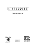
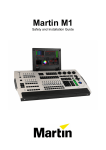
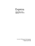
Live1
Compact Mixing Console
User Manual
Cadac Holdings Ltd.
One New Street
Luton
Bedfordshire
LU1 5DX
Telephone: +44 (0)1582 404202
Fax: +44 (0)1582 412799
Email:
General information: [email protected]
Service enquiries: [email protected]
3
IMPORTANT SAFETY INFORMATION
CAUTION: These servicing instructions are for use by qualified personnel
only. To reduce the risk of electric shock, do not perform any servicing
other than that contained in the User Manual unless you are qualified to
do so. Refer all servicing to qualified service personnel.
1. Read these instructions.
2. Keep these instructions.
3. Heed all warnings.
4. Follow all instructions.
5. Do not use this apparatus near water. Do not expose this apparatus to
dripping or splashing and ensure that no objects filled with liquids, such as
vases, are placed on this apparatus.
6. Clean only with a dry cloth.
7. Do not block any of the ventilation openings. Install in accordance with the
manufacturer’s instructions.
8. Do not install near any heat sources such as radiators, heat registers, stoves,
or other apparatus that produce heat.
9. Only use attachments/accessories specified by the manufacturer.
10. Refer all servicing to qualified service personnel. Servicing is required
when the apparatus has been damaged in any way, such as power-supply
cord or plug is damaged, liquid has been spilled or objects have fallen into
the apparatus, the apparatus has been exposed to rain or moisture, does not
operate normally, or has been dropped.
11. To completely disconnect mains power from this apparatus, the power
supply cord must be unplugged.
For US and CANADA only:
Do not defeat the safety purpose of the grounding-type plug. A grounding-type
plug has two blades and a third grounding prong. The wide blade or the third
prong are provided for your safety. When the provided plug does not fit into your
outlet, consult an electrician for replacement of the obsolete outlet.
The lightning flash with arrowhead symbol, within an equilateral triangle is
intended to alert the user to the presence of an uninsulated “dangerous voltage”
within the product’s enclosure that may be of sufficient magnitude to constitute
a risk of electric shock to persons.
The exclamation point within an equilateral triangle is intended to alert the user
to the presence of important operating and maintenance (servicing) instructions
in the literature accompanying the appliance.
Live1
Revision L1.1 2011-12
4
GENERAL PRECAUTIONS
Revision L1.1 2011-12
•
Do not place heavy objects on the control surface, expose it to sharp
objects or handle the console in any way that may cause damage e.g.
rough handling and/or excessive vibration.
•
Do not subject the equipment to dirt, dust, heat or vibration during operation
or storage. Never expose the console to rain or moisture in any form.
Should the console become wet, turn it off and disconnect from mains
without further delay. The console should be given sufficient time to dry out,
before recommencing operation.
•
When cleaning the console, never use chemicals, abrasive substances or
solvents.
•
The console control panel should be cleaned using a soft brush and a dry
lint-free cloth. For persistent marks, use a soft cloth and isopropyl alcohol.
Switches and potentiometers do NOT require cleaning or lubrication.
•
Keep these instructions for future reference. Follow all warnings in this
manual and those printed on the console.
•
The console must be connected following the guidance in this manual.
Never connect power amplifier outputs directly to the console. Connectors
and plugs must never be used for any other purpose than that for which
they are intended.
•
The PSU mains input must always be connected to correctly rated mains
power as referred to in this manual. The mains input must, at all times, be
connected to the local mains power supply using the supplied power cord.
In cases where the supplied plug does not fit, a qualified electrician must be
consulted.
•
The power cord must be routed in such a way that the risks of accidentally
stepping on it, stretching it or it being pinched, are minimized.
•
WARNING ! THIS EQUIPMENT MUST BE EARTHED !
•
Ventilation slots must never be covered or in any other way obstructed. Air
flow required for safe operation may otherwise be restricted. Where the
console is to be operated in its flight-case, then this must be located in such
a way that it allows for proper ventilation.
•
Refer servicing to qualified technical personnel only.
Live1
5
CONFORMITIES
Cadac Holdings Ltd.
One New Street
Luton Bedfordshire
LU 1 5 D X E n g l a n d
Te l : + 4 4 ( 0 ) 1 5 8 2 4 0 4 2 0 2
Fa x : + 4 4 ( 0 ) 1 5 8 2 4 1 2 7 9 9
Email: [email protected]
Declaration of Conformity
The Directives covered by this declaration: 2004/108/EC
The Products Covered by this Declaration: LIVE1 audio mixing consoles
The Basis on which Conformity is being Declared: The products identified above comply with
the requirements of the above EU Directive(s) by meeting the following standards:
BS EN 55103-1:2009
Product family standard for: audio, video, audio-visual and entertainment lighting
control apparatus for professional use. Part 1 – Emission.
BS EN 55103-2:2009
Product family standard for: audio, video, audio-visual and entertainment lighting
control apparatus for professional use. Part 2 – Immunity.
BS EN 61000-3 -2:2008
Electromagnetic Compatibility (EMC) Part 3. Limits. Section 2. Limits for harmonic
current emissions (equipment input current ≤ 16 A per phase).
BS EN 61000-3 -3:2006 + A2:2009 Electromagnetic Compatibility (EMC) Part 3. Limits. Section 3. Limitation of voltage
fluctuations and flicker in low voltage supply systems for equipment with rated
current ≤ 16 A.
BS EN 60065:2002 + A1:2006
Audio, Video and similar electronic apparatus. Safety requirements.
BS EN 61000-4-2:2009
Electrostatic discharge immunity test.
BS EN 61000-4-6:2009
Immunity to conducted disturbances.
BS EN 61000-4-11:2004
Immunity to voltage dips, short interruptions and voltage variations.
Signed:
Authority:
Operations Manager.
Date:
01 November 2010
Attention!
The attention of the specifier, purchaser, installer, or user is drawn to special measures and limitations to use
which must be observed when these products are taken into service to maintain compliance with the above
directives. Details of these special measures and limitations to use are available on request, and are also
contained in this Installation and User Manual.
Live1
Revision L1.1 2011-12
6
This page is intentionally left blank
Revision L1.1 2011-12
Live1
7
Contents
IMPORTANT SAFETY INFORMATION
3
For US and CANADA only:
3
GENERAL PRECAUTIONS
4
CONFORMITIES5
Introduction
8
Overview8
What’s in the box
8
Live1 – Main Feature Set
9
Mechanical dimensions
10
Powering the Live1
11
Control Surface layout
12
Rear Panel layout and connection details
13
Block Diagram
18
Module descriptions
20
Mono channels
20
Stereo channels
22
Sub/Aux/Mono Returns
24
Groups & metering
24
Subgroup meters
25
Aux sends
26
Aux returns
26
Stereo returns
27
Stereo return meters
27
L-R Master section
28
L-R master and metering
28
PFL/AFL and monitoring
29
Master Aux Pre/Post
29
Talkback30
Technical Specifications
Live1
31
Revision L1.1 2011-12
8
Introduction
Thank you for purchasing this Cadac Live1 audio mixing console.
First founded in 1967, Cadac products have indisputably become the
benchmark for sound reinforcement consoles. The Cadac Live1 Series is the
first truly compact Cadac mixer, and makes available many of the features of
our world-famous large-scale theatre and touring desks in a smaller, simpler
and more portable package. Nevertheless, you will still find the attention to
detail, high quality audio circuitry and reliability on which the reputation of the
Cadac brand is built enshrined in your Live1.
Overview
The Live1 is a high-quality, portable, non-modular audio mixing console
designed primarily for either FOH or monitor use as part of a live sound
reinforcement system in small to medium-sized venues. It is also suitable
for use as a high-quality tracking console for location or studio recording
applications. It is available in three frame sizes, with 8, 16 or 24 mono channels;
these configurations are referred to as the Live1 1642, Live1 2442 and Live1
3242 respectively.
In addition to the mono mic/line channels, all frame sizes contain four stereo line
input channels. The Live1 is also equipped with four pannable audio subgroups,
six mono auxiliary sends, six pannable mono auxiliary returns and two routable
stereo returns, as well as a comprehensive complement of talkback, metering
and master control facilities.
What’s in the box
The Live1 console is shipped in a triwall carton. Before unpacking, inspect that
the carton has not been damaged during shipping. If there are any signs of
damage, inform the shipping agent.
Inside the carton, you should find the following items. If any are missing, contact
your Cadac distributor immediately.
• Live1 mixing console
- PS1 Power Supply Unit
- DC power cable, 2m
• AC power cable
(with IEC and UK/European or US connector as appropriate)
• CD-ROM containing this manual
• Quick Start Guide
• Pair of brackets to allow rack mounting (Model 1642 only)
Revision L1.1 2011-12
Live1
9
Live1 – Main Feature Set
•
•
•
•
•
•
•
•
•
•
•
•
•
•
•
•
•
•
•
Live1
Suitable for FOH and/or monitor use
8, 16 or 24 mono channels
4 stereo channels
New design of mic amp
Per-channel phantom power and high pass filter
4 band EQ with swept mids (mono channels)
4 band EQ (stereo channels)
PFL/AFL and Mute
Per-channel signal presence LED
Per-channel -12/0/+12 dB signal level LEDs
6 auxiliary sends, switchable pre/post in pairs
4 audio subgroups
2 routable stereo returns
6 auxiliary returns
LR Master Output section with dual outputs and talkback section
100 mm faders on all inputs, subgroups, stereo returns and master
60 mm aux master faders
Talkback section
Bargraph metering on master, subgroups and PFL/AFL
Revision L1.1 2011-12
10
Mechanical dimensions
Width
436 mm
PSU
Width 483 mm
Width
612 mm
Width
788 mm
Depth
185 mm
Height
88 mm
(2RU)
Height
180 mm
Depth 563 mm
NOTE: when installing the Live1 in a permanent or semi-permanent situation,
an additional allowance must be made at the rear of the console for connectors
and cables.
Fitting the rack mounting kit (Model 1642 only)
The Live1 1642 is supplied with a pair of rack mounting brackets which permit
the mixer to be installed in a standard 19” equipment rack.
To install the brackets, remove the five upper screws (those closest to the mixer
control surface) which secure each metal end cheek to the chassis. Fit the rack
mounting brackets over the end cheeks and refit the five screws. Note that the
brackets are handed (i.e., one is designed to fit on the left hand side of the
console and the other to the right). This is indicated by an ‘L’ or ‘R’ label affixed
to the bracket.
Revision L1.1 2011-12
Live1
11
Powering the Live1
PS 1
ON
10063 PSU
DC
POWER
OUTPUT
THIS UNIT MUST BE
CONNECTED TO PROTECTIVE
EARTH
No user serviceable
parts
AC POWER
INPUT
100V to 240V
50/60Hz
ENERGY
HAZARD
+15V at 5A
-15V at 5A
+12V at 4A
Refer all maintenance
to a qualified
engineer
FOR USE WITH
CADAC LIVE1
SERIES ONLY
FUSE: T5A (100V)
T3.15A (240V)
Serial No.
The Live1 is powered from an external, rackmountable (2U) Power Supply Unit
(PSU). The AC mains switch is located on the front panel of the PSU, and the
mains is connected via an IEC receptacle on the rear panel. An IEC cable is
supplied with the PSU to connect this to the mains supply. The cable should be
fitted with a mains plug suitable for your country, if this is not the case, either
obtain one of the appropriate type, or replace the fitted plug with one of the
correct type. Note the mains cable colour coding is as follows:
Mains connection
Mains cable core colour
Neutral
Blue
Live
Earth (Ground)
Brown
Green/Yellow
The PSU in the Live1 is a “Universal” type, and may be connected to any AC
mains supply voltage of between 100 and 240 V, and frequency 50 or 60 Hz.
The IEC receptacle has an integral mains fuseholder (below the connector). If it
is necessary to replace this fuse, please only do so with one of the same type
and rating:
Fuse type
Fuse Rating
115 V AC
230 V AC
T5A (5 A)
T3.15A (3.15 A)
20 mm dia. anti-surge
This fuse is the only user-replaceable component the Live1 contains. A mains
fuse should never be replaced without first making an attempt to ascertain the
reason for its failure. If you are unsure why the fuse failed, or if the replacement
fuse also fails immediately, consult your Cadac dealer.
Live1
Revision L1.1 2011-12
12
DC connections
The rear panels of both the Live1 and the PS1 are fitted with a 10-pin connector.
A screened interconnecting cable is supplied with the mixer.
If it is necessary for the PS1 to be installed at a greater distance from the Live1
than the length of the supplied cable allows, users may manufacture their own
interconnecting cable, ensuring that all cores are wired pin-to-pin. The DC
connector pinout used on the Live1 is as follows:
Pin
1
2
Supply
+12 V
+12 V
Pin
6
7
Supply
0V
+15 V
4
-15 V
9
screen
3
5
+15 V
0V
8
10
-15 V
screen
The maximum permissible cable length to ensure reliable performance will
depend on i) the Live1 model and ii) the type of cable. Users wishing to
manufacture longer DC PSU cables are advised to contact Cadac’s Technical
Department for recommendations.
Revision L1.1 2011-12
Live1
13
Control Surface layout
CH 1
CH 2
CH 3
SIG
SIG
60
0
60
CH 4
0
60
CH 5
SIG
SIG
0
CH 6
SIG
0
60
CH 7
SIG
0
60
CH 8
SIG
0
60
ST 1
SIG
0
60
L
MIC
MIC
48V
48V
-18
-18
4k0
400
-18
4k0
400
Hz
Hz
+18
-18
-18
4k0
-18
-18
400
-18
4k0
400
Hz
+18
-18
-18
4k0
-18
-18
400
-18
4k0
400
Hz
+18
-18
-18
4k0
-18
∞
4k0
METER
METER
METER
METER
METER
18
18
18
18
18
18
12
12
12
12
12
12
6
6
6
6
6
6
3
3
3
3
3
3
0
SUM
0
-18
+18
-18
+18
HF
0
-18
-18
+18
+18
HF
0
-18
-18
+18
+18
HF
0
0
3
GRP
3
6
6
6
6
12
12
12
12
24
24
24
24
24
24
SIG
GRP/
AUX
SIG
SIG
GRP/
AUX
AUX 2 SND
SIG
GRP/
AUX
AUX 3 SND
0
SIG
RET/
AUX
AUX 4 SND
L-R
RET/
AUX
AUX 5 SND
+18
-18
PFL
PFL
PFL
PFL
PFL
PFL
M
M
M
M
M
M
∞
PHNS
0
AUX 6 SND
-18
0
-18
0
3
6
12
SIG
+18
0
3
0
AUX
6
AUX 1 SND
HF
0
3
TALKBACK
60
T/B
12
GRP/
AUX
400
+18
METER
3
R
SUM
-18
0
Hz
-18
R
10
0
400
+18
∞
10
SUM
∞
10
L
∞
R
SUM
-18
+18
HMF
0
Hz
+18
R
+18
HF
0
+18
HMF
0
-18
10
ST 4
∞
10
L
∞
48V
HPF
+18
HF
0
+18
HMF
0
Hz
+18
48V
HPF
+18
HF
0
+18
HMF
0
-18
10
ST 3
∞
10
L
MIC
48V
HPF
+18
HF
0
+18
HMF
0
Hz
+18
+18
HF
0
+18
HMF
0
-18
MIC
48V
HPF
HPF
+18
HF
0
+18
HMF
0
-18
MIC
48V
HPF
+18
HF
0
+18
HMF
MIC
48V
HPF
HPF
+18
HF
MIC
MIC
ST 2
∞
10
0
60
∞
MON
SOLO
18
12
LMF
LMF
0
600
60
LMF
0
600
60
LMF
0
600
60
LMF
0
600
60
LMF
0
600
60
LMF
0
600
60
LMF
0
600
60
HMF
0
600
HMF
0
+18
60
-18
HMF
0
+18
-18
HMF
0
+18
-18
6
0
+18
-18
3
0
Hz
Hz
+18
-18
Hz
+18
-18
Hz
+18
-18
Hz
+18
-18
Hz
+18
-18
Hz
+18
-18
Hz
+18
-18
LMF
+18
-18
LMF
0
+18
-18
LMF
0
+18
-18
LMF
0
+18
-18
3
0
+18
-18
10
10
10
10
10
10
5
5
5
5
5
5
6
12
LF
LF
0
LF
0
∞
0
∞
0
∞
0
∞
0
∞
0
∞
0
∞
0
AUX 4
∞
0
AUX 5
AUX 5
∞
0
AUX 3
∞
AUX 5
AUX 4
∞
0
AUX 5
∞
0
AUX 6
AUX 3
AUX 4
∞
0
AUX 5
∞
0
AUX 6
AUX 3
AUX 4
∞
0
AUX 5
∞
0
AUX 6
AUX 3
AUX 4
∞
0
AUX 5
∞
0
AUX 6
AUX 3
∞
0
AUX 5
∞
0
AUX 6
∞
AUX 5
∞
0
AUX 6
∞
AUX 5
∞
0
AUX 6
∞
AUX 5
AUX 6
AUX 6
1-2
1-2
1-2
1-2
1-2
1-2
1-2
1-2
3-4
3-4
3-4
3-4
3-4
3-4
3-4
3-4
3-4
3-4
3-4
3-4
PAN
L-R
L
PAN
0
R
PAN
0
PFL
PFL
CH 1
M
R
PAN
0
R
CH 3
M
PAN
0
R
CH 4
PAN
0
R
PAN
0
CH 5
L-R
L
PFL
M
+12
L-R
L
PFL
M
+12
L-R
L
PFL
CH 2
+12
L-R
L
PFL
M
+12
L-R
L
R
PFL
M
+12
PAN
0
CH 6
R
M
BAL
0
R
M
L-R
L
BAL
0
PFL
CH 8
+12
L-R
L
PFL
CH 7
+12
L-R
L
R
PFL
ST 1
M
+12
BAL
M
+12
R
BAL
0
20
20
20
20
30
30
30
30
30
∞
AFL
MODE
A1&2
PRE
A3&4
PRE
∞
∞
∞
∞
∞
A5&6
PRE
AUX 1 RTN
AUX 2 RTN
AUX 3 RTN
AUX 4 RTN
AUX 5 RTN
AUX 6 RTN
0
ST 3
∞
0
∞
∞
ST 4
+12
0
0
0
0
0
0
0
0
0
0
0
-12
-12
-12
-12
-12
-12
-12
-12
-12
-12
∞
0
∞
0
∞
L-R
∞
0
∞
0
AUX 6
0
∞
∞
0
R
0
L-R MASTER
ST RTN 2
1-2
3-4
3-4
0
0
L
R
0
∞
0
AUX 6
AUX 6
PFL
PFL
PFL
M
M
M
M
M
M
PAN
0
18
12
6
∞
3
AUX 5
PFL
PAN
0
MONO
0
AUX 5
PFL
PAN
0
∞
LINE
IN
L-R
∞
PFL
PAN
∞
l-R
ST RTN 1
1-2
GRP 4
L-R
L
∞
L-R
AUX 6
L-R
R
0
l-R
GRP 3
L-R
L
∞
AUX 5
GRP 2
R
0
L-R
AUX 5
AUX 6
L
-12
0
AUX 5
L-R
0
∞
GRP 1
0
-12
0
L-R
AUX 6
M
+12
0
R
PFL
M
+12
20
0
AFL
LVL
∞
0
L
PFL
ST 2
20
AUX 5
L-R
L
0
5
10
L-R
AUX 6
1-2
L-R
∞
0
1-2
R
∞
AUX 5
∞
0
1-2
L
5
10
30
SIG
0
5
10
∞
0
1-2
L-R
0
24
AUX 4
0
∞
0
0
5
10
AUX 3
0
0
5
10
∞
0
∞
0
AUX 4
0
∞
0
0
5
10
AUX 2
∞
0
AUX 3
AUX 4
0
∞
0
∞
0
0
∞
0
AUX 1
AUX 2
∞
0
AUX 3
AUX 4
∞
0
∞
0
∞
0
0
EQ
IN
AUX 1
AUX 2
∞
0
∞
0
∞
0
∞
0
LF
0
EQ
IN
AUX 1
AUX 2
∞
0
∞
0
∞
0
∞
0
LF
0
EQ
IN
AUX 1
AUX 2
∞
0
∞
0
∞
0
∞
0
LF
0
EQ
IN
AUX 1
AUX 2
∞
0
∞
0
∞
0
∞
0
LF
0
EQ
IN
AUX 1
AUX 2
∞
0
∞
0
AUX 4
0
∞
0
AUX 6
AUX 6
AUX 3
∞
0
∞
0
LF
0
EQ
IN
AUX 1
AUX 2
∞
0
∞
0
∞
0
∞
0
LF
0
EQ
IN
AUX 1
AUX 2
∞
0
AUX 3
AUX 4
AUX 4
∞
0
∞
0
∞
0
AUX 1
AUX 2
∞
0
AUX 3
AUX 3
∞
0
LF
0
EQ
IN
EQ
IN
AUX 1
AUX 2
AUX 2
LF
0
EQ
IN
AUX 1
AUX 1
LF
0
EQ
IN
EQ
IN
0
3
∞
6
12
24
SIG
PFL
M
10
10
10
10
10
10
10
10
10
10
10
10
10
10
10
10
10
10
10
5
5
5
5
5
5
5
5
5
5
5
5
5
5
5
5
5
5
5
0
0
0
0
0
0
0
0
0
0
0
0
0
0
0
0
0
0
0
5
5
5
5
5
5
5
5
5
5
5
5
5
5
5
5
5
5
5
10
10
10
10
10
10
10
10
10
10
10
10
10
10
10
10
10
10
10
20
20
20
20
20
20
20
20
20
20
20
20
20
20
20
20
20
20
20
30
40
60
30
40
60
30
40
60
30
40
60
30
40
60
30
40
60
30
40
60
30
40
60
30
40
60
30
40
60
30
40
60
30
40
60
30
40
60
30
40
60
30
40
60
30
40
60
30
40
60
30
40
60
30
40
60
∞
∞
∞
∞
∞
∞
∞
∞
∞
∞
∞
∞
∞
∞
∞
∞
∞
∞
∞
The model shown is the Live1 1642
Mic channels
Stereo line channels
Subgroups
Bargraph meters (Groups/Aux sends/Stereo returns)
Auxiliary send masters
Auxiliary returns
Stereo returns
L/R master section
AFL/PFL metering and control
Monitor and headphones
Talkback
Live1
Revision L1.1 2011-12
14
Rear Panel layout and connection details
16
11
10
15 9
RIGHT
LINE IN
2
4
14 5 6 17
2
3
TB
CH 7
LINE OUT
PHONES
ST1 R
ST1 L
ST2 R
ST2 L
3
CH 5
CH 3
CH 1
LITTLITE
1
LEFT
18
DC
POWER
INPUT
ST RT1 R
ST RT1 L
GP 4
GP 3
GP 2
GP 1
ST RT2 R
ST RT2 L
INS
INS
INS
INS
INS L
MON L
AUX 6
AUX 5
AUX 4
AUX 3
AUX 2
AUX 1
INS R
MON R
RTN 6
RTN 5
RTN 4
RTN 3
RTN 2
RTN 1
12 13
7
INS
DO
INS
DO
CH 8
ST3 R
ST3 L
ST4 R
ST4 L
INS
8
DO
INS
CH 6
INS
2
DO
3
DO
INS
DO
CH 4
INS
2
DO
CH 2
INS
DO
3
FOR USE WITH
CADAC PS1
SERIES ONLY
The model shown is the Live1 1642
No.
Connection
Qty. of connectors
1
Mono channel inputs
2
Mono channel inserts
3
Mono channel direct outputs
4
Stereo channel inputs
8 (4 x L+R)
5
Subgroup outputs
4
6
Subgroup inserts
4
7
Auxiliary sends
6
8
Auxiliary returns
6
9
Stereo returns
4 (2 x L+R)
10
L-R Master outputs
2 (L+R)
11
Line out (unbal. L-R Master)
1
12
Master inserts
2 (L+R)
13
Monitor outputs
2 (L+R)
14
Headphone output
1
15
Talkback mic
1
16
Line In (to stereo mix)
1
17
Littlites sockets
1 or 2*
18
PSU connector
1
8, 16 or 24*
* Depending on frame size
Revision L1.1 2011-12
Live1
15
1. Mono channel inputs – 3-pin Neutrik Combo A Series connectors. These
accept either a standard 3-pin XLR male plug for microphone use, or a
1/4” (6.35 mm) 3-pole (TRS) jack plug for line level use. The inputs are
electronically balanced; the mic inputs have an impedance of 1.2 kohms
and the line inputs an impedance of approximately 10 kohms. The
sensitivity of the line input is 16 dB lower than that of the mic input, and the
maximum input level is +21 dBu. 48 V phantom power is available at the
XLR pins, via a switch on the channel strip. The connector should be wired
as follows:
XLR Pin
TRS jack
Connection
1
Sleeve
Screen
2
Tip
Signal ‘hot’ (phase)
3
Ring
Signal ‘cold’ (antiphase)
2. Mono channel inserts - ¼” (6.35 mm) 3-pole (TRS) jack sockets, for the
connection of external processing. The insert is post-EQ and pre-fade/mute.
Both send and return are unbalanced, at a nominal level of 0 dBu. The
output impedance of the send is 100 W. Max. return input level is +10 dBu,
with an impedance of 10 kW. The connector should be wired as follows:
Pin
Connection
Tip
Send
Ring
Return
Sleeve
Screen (common)
3. Mono channel direct outputs – ¼” (6.35 mm) 3-pole (TRS) jack sockets.
These are unbalanced post-fade/mute outputs from each mic channel, and
can be used for multitrack recording or other purposes. The outputs have a
nominal level of 0 dBu and a max. level of +21 dBu. The connector should
be wired as follows:
Pin
Connection
Tip
Signal ‘hot’ (phase)
Ring
Sleeve
Screen
4. Stereo channel inputs - ¼” (6.35 mm) 3-pole (TRS) jack sockets. The
inputs to the four stereo line channels are balanced, with separate sockets
for left and right inputs. Nominal input level is 0 dBu into 10 kW, maximum
input level +21 dBu. The connector should be wired as follows:
Pin
Connection
Tip
Signal ‘hot’ (phase)
Ring
Signal ‘cold’ (antiphase)
Sleeve
Live1
Screen
Revision L1.1 2011-12
16
5. Subgroup outputs – In addition to acting as subgroups of the main mix,
the four individual group outputs are also available. They are post-subgroup
fade/mute. Connectors are ¼” (6.35 mm) 3-pole (TRS) jack sockets;
nominal output level is 0 dBu, max. output level is +21 dBu. Wiring as per
table at [4] above.
6. Subgroup inserts - ¼” (6.35 mm) 3-pole (TRS) jack sockets, for the
connection of external processing across the whole subgroup. The insert is
pre-fade/mute. Both send and return are unbalanced, at a nominal level of
0 dBu. Max. return input level is +10 dBu, with an impedance of 10 kW.
Wiring is as per table at [2] above.
7. Auxiliary Sends – the six aux. send outputs are balanced, and are
available at ¼” (6.35 mm) 3-pole (TRS) jack sockets. Nominal output level
is 0 dBu, maximum output level +21 dBu. Wiring is as per table at [4] above.
8. Auxiliary Returns – the six aux. return inputs are balanced, and are on
¼” (6.35 mm) 3-pole (TRS) jack sockets. Nominal input level is 0 dBu,
maximum input level +21 dBu. Wiring is as per table at [4] above.
9. Stereo returns – the inputs of the two stereo returns are balanced, with
separate sockets for left and right inputs. The connectors are ¼” (6.35 mm)
3-pole (TRS) jack sockets. Nominal input level is 0 dBu, maximum input
level +21 dBu. Wiring is as per table at [4] above.
10. L-R Master outputs (main) – the main stereo output of the Live1 is
available in both balanced and unbalanced (see [11] below) form on two
different connector types. The two pairs of outputs are buffered from each
other. The main (balanced) outputs are on two (L & R) 3-pin male XLR
connectors. Nominal output level is 0 dBu, maximum output level +21 dBu.
Wiring is per the table at [1] above.
11. Mono Master output - A secondary, balanced mono output, operating at
the same levels is also available. This connector is labelled LINE OUT on
the rear panel. Nominal output level is 0 dBu, source impedance 100 W.
The connector is a ¼” (6.35 mm) 3-pole (TRS) jack socket; note that this
carries an (L+R) sum of the main stereo output. Wiring is per the table at
[4] above.
12. Master inserts – two ¼” (6.35 mm) 3-pole (TRS) jack sockets, for the
connection of external processing across the main outputs. The insert
is post-EQ and pre-fade/mute. Both send and return are unbalanced,
at a nominal level of 0 dBu. Max. return input level is +10 dBu, with an
impedance of 10 kW. Wire as per table at [2] above.
13. Monitor outputs – these carry the AFL/PFL output of the mixer for
monitoring and checking purposes. As AFL is stereo, separate left and right
outputs are provided. The outputs are electronically balanced on, ¼” (6.35
mm) 3-pole (TRS) jack sockets. Nominal output level is 0 dBu, maximum
level +21 dBu. Wire as per the table at [4] above.
Revision L1.1 2011-12
Live1
17
14. Headphone output – this is a single ¼” (6.35 mm) 3-pole (TRS) jack
socket carrying the same signal as at [13] above, but in unbalanced form
and at a level suitable for driving headphones of 16 W impedance, or higher.
This connector should be wired as follows:
Pin
Connection
Tip
Left monitor output
Ring
Right monitor output
Sleeve
Screen (common)
15. Talkback mic – a 3-pin female XLR for connection of a talkback
microphone. Sensitivity and input impedance are the same as those for
the mic channels. Note that phantom power is permanently active at this
connector. The connector should be wired as per the table at [1] above.
16. Line in – this is an unbalanced stereo line input to the Master L/R mix.
The L and R buses are fed equally. Nominal input level is 0 dBu, input
impedance 10 kW. The connector is a 3-pole ¼” (6.35 mm) jack socket, and
should be wired as per the table at [4] above.
17. Littlites – 3-pin male XLR connector(s), providing 12 Vdc at for the
connection of Littlite® lamps. The current capability of each connector is
1 A. The DC supply has an internally resettable fuse. The Live1 Model
1642 is fitted with one Littlite connector, while Models 2442 and 3242 each
have two. Littlites are directly compatible; if using other types of lights, the
connectors should be wired as follows:
PIN
Use
1
n/c
2
+12 V
3
0V
18. Mains input – see “Powering the Live1” on page 11
It is always good operating practice to turn a mixer on BEFORE turning on
the amplifiers, etc., to which its outputs are connected. Similarly, always
turn the amplifiers off BEFORE turning the mixer OFF.
Live1
Revision L1.1 2011-12
48v ON
AFL L
AFL R
AUX 1 & 2 PRE
AUX 3 & 4 PRE
AUX 5 & 6 PRE
AUX 1
AUX 2
AUX 3
AUX 4
AUX 5
AUX 6
PFL
GROUP 1
GROUP 2
GROUP 3
GROUP 4
Block Diagram
STEREO L
STEREO R
18
48v
METER
36 6
0
6
PFL & AFL
GAIN
XLR-JACK COMBINED
CONNECTOR
HPF
MIC
2
3
1
EQ IN
HPF
80Hz
MIC
0 - 60dB
EQ
80Hz
60-600Hz 400-4kHz 12kHz
CHANNEL
INSERT
Buffer
0dB
Buffer
0dB
LINE INPUT
(16dB PAD)
PAN
Buffer
4.5dB
Buffer
10dB
Buffer
4.5dB
MUTE
GP 1 & 2
DIRECT
OUTPUT
GP 3 & 4
Bal OP
0dB
STEREO
AUX 1
LEVEL
AUX 2
LEVEL
AUX 3
LEVEL
AUX 4
LEVEL
AUX 5
LEVEL
Mono Input Channel
8x for Live1 1642
16x for Live1 2442
24x for Live1 3242
AUX 6
LEVEL
TRIM
METER
36 6
STEREO
INPUT L
0
6
PFL & AFL
EQ IN
Bal IP
+/-20dB
STEREO EQ
80Hz
600Hz
4kHz
12kHz
80Hz
4kHz
12kHz
Buffer
10dB
TRIM
600Hz
MIX
0dB
STEREO
INPUT R
MIX
0dB
Bal IP
+/-20dB
Buffer
10dB
BAL
Buffer
4.5dB
Buffer
4.5dB
GP 1 & 2
MUTE
GP 3 & 4
STEREO
AUX 1
LEVEL
AUX 2
LEVEL
AUX 3
LEVEL
AUX 4
LEVEL
AUX 5
Stereo Input Channel
4x for all versions of Live1
Revision L1.1 2011-12
LEVEL
AUX 6
LEVEL
Live1
AUX 1 & 2 PRE
AUX 3 & 4 PRE
AUX 5 & 6 PRE
AFL L
AFL R
AUX 1
AUX 2
AUX 3
AUX 4
AUX 5
AUX 6
STEREO L
STEREO R
GROUP 1
GROUP 2
GROUP 3
GROUP 4
19
METER
36 30 24 18 12 6
AUX BUS
SELECTION
LINK
AUX
RETURN
STEREO
3
0
3
6 12 18
MIX
0dB
AUX O/P
LEVEL
Bal IP
0dB
Buffer
10dB
2
3
1
Bal OP
0dB
PFL & AFL
AUX 5
LEVEL
MUTE
AUX 6
LEVEL
METER
36 6
0
6
GROUP
INSERT
GROUP BUS
SELECTION
LINK
MIX
0dB
Buffer
0dB
GROUP O/P
Buffer
10dB
2
3
1
Bal OP
0dB
PFL & AFL
MUTE
Buffer
4.5dB
PAN
Buffer
4.5dB
STEREO
Groups 1-4 , Aux send 1-4, Aux return 1-4
4x for all versions of Live1
AUX
RETURN
STEREO
LEVEL
Bal IP
0dB
METER
36 30 24 18 12 6
AUX BUS
SELECTION
LINK
METER
36 6
0
6
3
0
3
6 12 18
MIX
0dB
AUX O/P
PFL & AFL
Buffer
10dB
2
3
1
Bal OP
0dB
STEREO
RETURN L
PFL & AFL
Bal IP
0dB
Buffer
10dB
MUTE
MIX
0dB
STEREO
RETURN R
MIX
0dB
Bal IP
0dB
Buffer
10dB
GP 1 & 2
MUTE
GP 3 & 4
STEREO
AUX 5
LEVEL
AUX 6
Stereo Returns 1-2, Aux Sends 5-6, Aux Returns 5-6
2x for all versions of Live1
LINE
INPUT
LEVEL
LEVEL
Buffer
0dB
LEVEL
Buffer
0dB
METER
Buffer
0dB
36 30 24 18 12 6
MIX
0dB
36 30 24 18 12 6
BAL
TALKBACK
MIC
GRPS
MIX
0dB
Buffer
10dB
Buffer
0dB
0
3
6 12 18
3
0
3
6 12 18
Bal OP
0dB
MIX
0dB
Buffer
4.5dB
Bal OP
0dB
Buffer
0dB
2
3
1
2
3
1
MAIN O/P
LEFT
MAIN O/P
RIGHT
MUTE
Buffer
10dB
MAIN
INSERT
RIGHT
GRPS
3
MONO
MAIN
INSERT
LEFT
GAIN
MIC
0 - 60dB
METER
Buffer
4.5dB
Buffer
0dB
48v
2
3
1
Buffer
0dB
LINE O/P
Buffer
0dB
Buffer
0dB
MIX
0dB
GRPS
AFL TRIM
MIX
0dB
v
AUX 1&2
PRE
MIX
0dB
LEVEL
LEVEL
LEVEL
Buffer
10dB
LEVEL
Buffer
10dB
HEADPHONES
O/P
Buffer
10dB
Buffer
10dB
MON O/P
LEFT
METER
36 30 24 18 12 6
LEVEL
3
0
3
6 12 18
3
0
3
6 12 18
AUX 3&4
PRE
METER
Live1
Bal OP
0dB
Buffer
10dB
Bal OP
0dB
MON O/P
RIGHT
Stereo Master, PFL Output and TalkBack
1x for all versions of Live1
Buffer
10dB
36 30 24 18 12 6
LEVEL
AUX 5&6
PRE
Revision L1.1 2011-12
20
Module descriptions
Mono channels
SIG – green signal presence LED, illuminates when channel signal level is
approx. -36 dBu. This LED indicates the level post-EQ, pre-insert, so is affected
by the setting of the MIC gain control.
Mic pre:
MIC – sets mic amp gain; range of adjustment is 0 to 60 dB. When using the input
channel with line level sources, this control should be set at minimum (0 dB).
48V – press to enable 48 V phantom power at the mic input XLR. An adjacent
red LED illuminates to warn that phantom power is active.
HPF – press to insert a high pass filter in the signal path. The filter rejects
signals below 80 Hz, with a slope of 12 dB/oct. An adjacent yellow LED
illuminates to confirm that the filter is in circuit.
Equaliser:
HF – shelving filter providing 18 dB of cut or boost above 12 kHz.
HMF – bell filter providing 18 dB of cut or boost at frequency set by the
associated Hz control
Hz – selects centre frequency of HMF EQ section; range 400 Hz to 4 kHz
LMF – bell filter providing 18 dB of cut or boost at frequency set by the
associated Hz control
Hz – selects centre frequency of LMF EQ section; range 60 Hz to 600 Hz
LF – shelving filter providing 18 dB of cut or boost below 80 Hz.
EQ IN – when pressed, the EQ section is placed in the signal path. An adjacent
yellow LED illuminates to confirm this.
Auxiliary sends:
The six aux sends are identical. All sends are mono, and each has its own send
level control. With the control fully anticlockwise, the send is off. The sends may
be selected as pre- or post-fade in pairs – i.e., 1 & 2, 3 & 4 and 5 & 6 – from
the master section (see “Master Aux Pre/Post” on page 29). Note that the
channel MUTE button mutes both pre-fade and post-fade sends.
Routing & panning:
The routing buttons are non-interlocking; the channel signal may be sent to all
subgroups and/or the master output simultaneously if wished. Subgroups are
used when you want to have control of the overall level of several inputs on a
single fader.
1-2 – pressing this button sends the post-fade signal to subgroups 1 and 2, via
the PAN control. An adjacent green LED illuminates to confirm the routing.
3-4 – pressing this button sends the post-fade signal to subgroups 3 and 4, via
the PAN control. An adjacent green LED illuminates to confirm the routing.
Revision L1.1 2011-12
Live1
21
L-R – pressing this button sends the post-fade signal to the master L and R
outputs, via the PAN control. An adjacent red LED illuminates to confirm the
routing.
PAN – provides conventional odd-even panning. The control is calibrated
L - 0 - R; in the L position, routing is to subgroups 1 and 3 and Master L only;
in the R position, routing is to subgroups 2 and 4 and Master R only. In the
0 position, the channel signal is routed equally to all selected groups. The
pan control applies a level offset (max. -4.5 dB at the 0 setting) to maintain
approximately constant volume over the control’s range.
PFL – a latching button which routes the signal in the channel to the internal
PFL/AFL system so that it may be monitored on local speakers or headphones
connected at the MON OUT or HEADPHONES connectors respectively. The
signal continues to route normally while the PFL button is pressed. An adjacent
green LED illuminates to confirm that PFL/AFL is active.
Monitoring of channels may be either pre-fade (PFL) or after-fade (AFL); the
mode is selected globally from the Master section (see “AFL Mode” on page
29). In PFL mode, the signal is heard in mono, and the channel fader and
MUTE button have no effect on the level. In AFL mode, the signal is heard in
stereo, at the correct position in the overall stereo image, as determined by the
PAN control. In this case, the channel fader setting will affect the level of the
signal heard, but the MUTE button will have no effect.
Fader section:
Scribble strip – a writing strip is provided to allow channel identification. The
mono channels are designated CH1 to CH8 (or CH16, or CH24)*.
M – Pressing the M (MUTE) button mutes all outputs from the channel: via the
subgroup and master routing, all auxiliary sends, the channel Direct Output,
and any AFL monitoring. The sole exception is PFL monitoring, which remains
active. An adjacent red LED illuminates to confirm that MUTE is applied.
Signal level LEDs – three LEDs indicate the signal level, post-EQ, pre-insert,
as follows:
red:
+12 dBu
yellow: 0 dBu
yellow: -12 dBu
Fader – a 100 mm plastic conductive fader with a white knob adjusts the overall
channel level.
* Depending on frame size
Live1
Revision L1.1 2011-12
22
Stereo channels
Input gain:
L and R – two controls setting input gain of left and right channels
independently; fully clockwise, the gain is 0 dB; fully anticlockwise is effectively
‘off’.
SUM – pressing this button sums the left and right inputs (post input gain
controls), and the mix is fed equally to the left and right legs of the stereo
channel. An adjacent green LED illuminates to confirm that the channel is
operating in mono.
Equaliser:
HF – shelving filter providing 18 dB of cut or boost above 12 kHz
HMF – bell filter providing 18 dB of cut or boost, centred on 4 kHz
LMF – bell filter providing 18 dB of cut or boost, centred on 600 Hz
LF – shelving filter providing 18 dB of cut or boost below 80 Hz
EQ IN – when pressed, the EQ section is placed in the signal path. An adjacent
yellow LED illuminates to confirm this.
Auxiliary sends:
The six aux sends are identical. All sends are mono, and in the stereo channels,
each receives an L+R mix of the left and right legs. Each has its own send level
control. With the control fully anticlockwise, the send is off. The sends may
be selected as pre- or post-fade in pairs – i.e., 1 & 2, 3 & 4 and 5 & 6 – from
the master section (see “Master Aux Pre/Post” on page 29). Note that the
channel MUTE button mutes both pre-fade and post-fade sends.
Routing & panning:
The routing buttons are non-interlocking; the channel signal may be sent to all
subgroups and/or the master output simultaneously if wished.
1-2 – pressing this button sends the post-fade signal to subgroups 1 and 2, via
the PAN control. An adjacent green LED illuminates to confirm the routing.
3-4 – pressing this button sends the post-fade signal to subgroups 3 and 4, via
the PAN control. An adjacent green LED illuminates to confirm the routing.
L-R – pressing this button sends the post-fade signal to the master L and R
outputs, via the PAN control. An adjacent red LED illuminates to confirm the
routing.
BAL – allows adjustment of the image of the stereo signal. The control is
calibrated L - 0 - R; in the L and R positions, a level offset of 4.5 dB is applied
to the two legs. In the 0 position, the stereo image of the original input signal is
maintained.
PFL – pressing the PFL button routes the signal in the channel to the internal
PFL/AFL system so that it may be monitored on local speakers or headphones
connected at the MON OUT or HEADPHONES connectors respectively. The
signal continues to route normally while the PFL button is pressed. An adjacent
green LED illuminates to confirm that PFL/AFL is active.
Revision L1.1 2011-12
Live1
23
Monitoring of stereo channels may be either pre-fade (PFL) or after-fade (AFL);
the mode is selected globally from the Master section (see “AFL Mode” on page
29). In PFL mode, the signal heard is a mono sum of the L and R legs, and
the channel fader and MUTE button have no effect on the level. In AFL mode,
the full stereo signal is heard, (as modified by the BAL control); the channel
fader setting will affect the level of the signal heard, but the MUTE button will
have no effect.
Fader section:
Scribble strip – a writing strip is provided to allow channel identification. The
stereo channels are designated ST1 to ST4.
M – Pressing the M (MUTE) button mutes all outputs from the channel: via the
subgroup and master routing, all auxiliary sends, and any AFL monitoring. The
sole exception is PFL monitoring, which remains active. An adjacent red LED
illuminates to confirm that MUTE is applied.
Signal level LEDs – three LEDs indicate the signal level, post-EQ, pre-insert, as
follows:
red: +12 dBu
yellow: 0 dBu
yellow: -12 dBu
The LEDs indicate a mono sum of the left and right legs.
Fader – a 100 mm plastic conductive fader with a red knob adjusts the overall
stereo channel level.
Live1
Revision L1.1 2011-12
24
Sub/Aux/Mono Returns
Groups & metering
Signals routed from the input channels (mono and stereo) to the four subgroups
are summed in the subgroup section and the level of their mix controlled by the
subgroup faders. Each subgroup itself may then be routed into the L-R Master
mix (although its output is also available at the rear panel (at GP 1 to GP 4) for
recording or other purposes).
Revision L1.1 2011-12
Live1
25
Subgroup meters:
METER – the signal level in each subgroup (or auxiliary
send – see below) may be monitored by the 10-segment
LED bargraph meter at the top of each subgroup strip. Note
the bottom LED is labelled SIG, and illuminates at a signal
level of approx. -36 dBu. The LEDs are colour-coded as
follows:
red:
+18 dBu
yellow: -24 dBu to +12 dBu
green:
SIG
GRP/AUX – the meters may be individually switched to monitor the level of Aux.
Sends 1 to 4 instead of that of the subgroups. Pressing this button selects AUX,
and an adjacent red LED illuminates to confirm the setting. This is useful during
set-up when the console is being used for FOH work, when FX send levels may
be set and then left, the meters being returned to subgroup mode during the
show. When the Live1 is being used as a monitor mixer, normal practice would
be to switch all these meters to AUX permanently.
Note that the meters show pre-fade signals whether set to GRP or AUX; i.e., in
GRP mode, they indicate the subgroup level pre the subgroup fader, and in AUX
mode, the Aux send level pre the Aux Master fader.
L-R – pressing this button sends the post-fade subgroup signal to the
L-R master section, via the PAN control. An adjacent red LED illuminates
to confirm the routing. The subgroup signals are still available at the rear
panel GP1 – GP4 connectors even if this routing is not selected.
PAN – allows the mono subgroup to be panned anywhere in the stereo
image of the L-R Master output. When in its centre (0) position, the
subgroup signal is centrally positioned in the stereo mix.
PFL – pressing the PFL button routes the subgroup to the internal
PFL/AFL system so that it may be monitored on local speakers or
headphones connected at the MON OUT or HEADPHONES connectors
respectively. The subgroup continues to operate normally while the PFL
button is pressed. An adjacent green LED illuminates to confirm that
PFL/AFL is active.
Like the input channels, the subgroups may be monitored either pre-fade
(PFL) or after-fade (AFL); the mode is selected globally from the Master
section (see “AFL Mode” on page 29). In PFL mode, the signal is
heard in mono, and the subgroup fader and MUTE button have no effect
on the level. In AFL mode, the signal is heard in stereo, at the correct
position in the L-R Master image, as determined by the subgroup PAN
control. In this case, the channel fader setting will affect the level of the
signal heard, but the MUTE button will have no effect.
M – Pressing the M (MUTE) button mutes the subgroup; this includes the rear
panel GROUP output and routing to the L-R Master (if selected). The exception
is PFL/AFL monitoring, which remains active. An adjacent red LED illuminates
to confirm that MUTE is applied.
Fader – a 100 mm plastic conductive fader with a blue knob adjusts the overall
subgroup level. The pre-fade subgroup signal may be metered at the top of the
subgroup strips (see “Meter” above).
Live1
Revision L1.1 2011-12
26
Aux sends
There are six Auxiliary Send Master sections on the
Live1. Signals sent from the input channels to the six
Auxiliary sends are summed in the Aux. Master sections
(located in the Sub/Aux/Mono Return and Stereo Return
strips), where the overall Auxiliary send output level can
be set with the Aux Master faders. The Auxiliary outputs
are designated AUX 1 to AUX 6 on the rear panel.
PFL - pressing the PFL button allows the Auxiliary send
to be monitored by the PFL/AFL system in the same way
as channels and subgroups. The Aux. send continues
to operate normally while the PFL button is pressed. An
adjacent green LED illuminates to confirm that PFL/AFL
is active.
Because the Auxiliary sends are always mono, monitoring will be in mono
whether global PFL or AFL mode is selected. In PFL mode, the signal will be
heard pre the Aux. Master fader, in AFL mode, it will be heard post the fader.
The Aux. send MUTE button does not affect the PFL/AFL monitoring, regardless
of the global mode.
M – Pressing the M (MUTE) button mutes the Auxiliary send. As described
above, PFL or AFL monitoring are unaffected. An adjacent red LED illuminates
to confirm that MUTE is applied.
Fader – a 60 mm plastic conductive fader with a grey knob adjusts the overall
Auxiliary Master level. The pre-fade Aux. Master signal may be metered at the
top of the subgroup strips (Auxes 1 to 4) or the stereo return strips (Auxes 5 and
6) - see “Meter” on page 25.
Aux returns
The Live1 is equipped with six mono Auxiliary returns, which
may be used for FX returns or other additional inputs into
the mix. The inputs are labelled RTN 1 to RTN 6 on the rear
panel. The signal at each return is routed at equal levels to
the left and right legs of the L-R Master output.
Note that the six Auxiliary returns have no internal relationship with the six
Auxiliary sends (though it would be logical to use the same numbered send and
return for an external FX loop).
L-R – a rotary control which adjusts the overall mono return level to the L-R
Master mix.
AUX 5 and AUX 6 – it is possible to “spin” some of the Aux. return signals back
into Aux. sends 5 and/or 6. The most likely use of this would be to add echo
or reverb to a foldback send; in this case Auxes 5 & 6 would be used to derive
the foldback mix, and one of Auxes 1 to 4 as an FX send to the external reverb
device. The reverb device output is then brought back into the mixer via an Aux.
return (or a pair), and added to the foldback as required via these controls. In
this way, different amounts of echo can be added to the same input signal in the
main mix and the artist’s foldback.
This “spin” facility is not available for Aux. returns 5 and 6.
Revision L1.1 2011-12
Live1
27
Stereo returns
As well as the six mono Aux. sends, the Live1 is equipped with two stereo
returns, which are routable to the subgroups and L-R Master output in a similar
manner to the input channels. The stereo return inputs are labelled ST RT 1 L,
ST RT 1 R and ST RT 2 L, ST RT 2 R on the rear panel.
Stereo return meters:
METER – the signal level in each stereo return (or auxiliary send – see below)
may be monitored by the 10-segment LED bargraph meter at the top of each
stereo return strip. Note the bottom LED is labelled SIG, and illuminates at a
signal level of approx. -36 dB. The LEDs are colour-coded as follows:
red:
+18 dBu
yellow: -24 dBu to +12 dBu
green:
SIG
RET/AUX – the meters may be individually switched to monitor the level of Aux.
Sends 5 to 6 instead of that of the stereo returns. (This is useful during set-up
when the console is being used for FOH work, when FX send levels may be
set and then left, the meters being returned to stereo return mode during the
show.) Pressing this button selects AUX, and an adjacent red LED illuminates to
confirm the setting.
Note that the meters show pre-fade signals whether set to RET or AUX; i.e., in
RET mode, they indicate the stereo return level pre the return fader, and in AUX
mode, the Aux. send level pre the Aux. Master fader.
1-2 – pressing this button sends the stereo return signal to subgroups 1 and
2, left leg to 1, right leg to 2. An adjacent green LED illuminates to confirm the
routing.
3-4 – pressing this button sends the stereo return signal to subgroups 3 and
4, left leg to 3, right leg to 4. An adjacent green LED illuminates to confirm the
routing.
L-R – pressing this button sends the stereo return signal to the L-R Master, left
to L, right to R. An adjacent red LED illuminates to confirm the routing.
The routing buttons are non-interlocking; the stereo return signal may be sent to
all subgroups and/or the L-R Master simultaneously if wished.
AUX 5 and AUX 6 – the stereo returns also feature the “spin” controls described
on page 26. In this case, a mono L+R sum of the stereo return signal is sent
to Aux. send 5 and/or 6.
PFL – pressing the PFL button routes the signal in the channel to the internal
PFL/AFL system so that it may be monitored on local speakers or headphones
connected at the MON OUT or HEADPHONES connectors respectively. The
signal continues to route normally while the PFL button is pressed. An adjacent
green LED illuminates to confirm that PFL/AFL is active.
Monitoring of stereo returns may be either pre-fade (PFL) or after-fade (AFL);
the mode is selected globally from the Master section (see “AFL Mode on page
29). In PFL mode, the signal heard is a mono sum of the L and R legs, and
Live1
Revision L1.1 2011-12
28
the stereo return fader and MUTE button have no effect on the level. In AFL
mode, the full stereo signal is heard. In this case, both the stereo return fader
and MUTE button will affect the signal heard.
M – Pressing the M (MUTE) button mutes the stereo return. This will mute the
return’s feed to the subgroups, the L-R Master output, Aux. sends 5 and 6 and
any AFL monitoring. The exception is PFL monitoring, which remains active. An
adjacent red LED illuminates to confirm that MUTE is applied.
Fader – a 100 mm plastic conductive fader with a red knob adjusts the overall
stereo return level. The pre-fade stereo return signal may be metered at the top
of the strips, provided the RET/AUX button is set to RET.
L-R Master section
L-R master and metering
LINE IN – A rear panel input (‘LINE INPUT’) to the L-R Master is provided; this
is useful for connecting a CD player, laptop or similar for pre-show music, and
avoids the use of a stereo channel or return for a source not used during the
show. The LINE IN control sets the level of this input.
MONO – pressing the MONO button sums the left and right legs of the L-R
Master output. The left and right outputs will have the same signal. An adjacent
green LED illuminates to warn that MONO has been selected.
Meters – a dual, 10-segment LED bargraph meter indicates the level of the L-R
Master output. The metering point is post-fade, but pre-mute. It is also post the
MONO button. Note the bottom LED is labelled SIG, and illuminates at a signal
level of approx. -36 dBu. The LEDs are colour-coded as follows:
yellow: -24 dBu to +12 dBu
red:
+18 dBu
green:
SIG
PFL – pressing the PFL button routes the L-R Master signal to the internal
PFL/AFL system so that it may be monitored on local speakers or headphones
connected at the MON OUT or HEADPHONES connectors respectively. The
signal continues to route normally while the PFL button is pressed. An adjacent
green LED illuminates to confirm that PFL/AFL is active.
Monitoring of the L-R Master output may be either pre-fade (PFL) or after-fade
(AFL); the mode is selected globally from the Master section (see “AFL Mode
on page 29). In PFL mode, the signal heard is a mono sum of the L and R
legs, and the master fader and MUTE button have no effect on the level. In AFL
mode, the full stereo signal is heard; the channel fader setting will affect the
level of the signal heard, but the MUTE button will have no effect.
M – Pressing the M (MUTE) button mutes the L-R Master output. An adjacent
red LED illuminates to confirm that MUTE is applied.
Fader – a 100 mm plastic conductive fader with a black knob adjusts the L-R
Master output level.
Revision L1.1 2011-12
Live1
29
PFL/AFL and monitoring
This section of the Master strip is concerned with selection and control of
the Live1’s PFL/AFL system, which permits inputs, sends and returns to
be monitored either individually or in combination. Monitoring may be via
headphones plugged into the rear panel PHONES connector, or via an amplifier
and loudspeakers connected at the rear panel MON L and MON R connectors.
Note that if headphones are used, their impedance should be 16 Ω or greater.
PHNS – this controls the level of PFL/AFL signal sent to the headphone socket.
MON – this controls the level of PFL/AFL signal sent to the rear panel monitor
outputs.
Meters – a dual, 10-segment LED bargraph meter indicates the level of the
signal(s) currently being monitored by the PFL/AFL system. The meter reading
is independent of the settings of the PHNS and MON controls. In PFL mode,
the left and right bargraphs should show identical levels, but readings will differ,
reflecting stereo placement, in AFL mode. Note the bottom LED is labelled SIG,
and illuminates at a signal level of approx. -36 dBu. The LEDs are colour-coded
as follows:
red:
+18 dBu
yellow: -24 dBu to +12 dBu
green:
SIG
AFL LEVEL – this adjusts the level of the AFL signal. It has no function if global
AFL mode is not selected. It allows the volume of the monitoring in AFL mode to
be trimmed to match what is heard in PFL mode.
AFL MODE – pressing this button switches all PFL/AFL circuitry throughout the
whole mixer into AFL mode. In this mode, when any PFL button on the mixer is
pressed, signal metering and monitoring by the PFL/AFL system will be post the
relevant fader(s), and in stereo. Thus, the relative levels and stereo imaging of
a group of inputs can be assessed. An adjacent red LED illuminates to indicate
the selection of AFL mode.
When not pressed, PFL mode is selected. Pressing any PFL button on the
console will cause the relevant signal to be metered and monitored in mono,
and at ‘full’ level – i.e., one that is not affected by the fader controlling the signal
in the mix.
PFL is useful when checking all that individual sources feeding the mixer
are present and correct. AFL is more useful for listening to several signals in
combination (i.e. group of voices, or a drum kit), so that their relevant level and
stereo placement can be checked.
Master Aux Pre/Post
These three buttons globally switch the Auxiliary sends in pairs to be pre- or
post-fade. Note that all Auxiliary sends are derived post-mute in the channel or
return in which the send is located.
A1&2 PRE – press this button to make all mixer sends to Auxiliaries 1 and 2
pre-fade. An adjacent green LED illuminates to confirm PRE mode has been
selected.
A3&4 PRE – press this button to make all mixer sends to Auxiliaries 3 and 4
pre-fade. An adjacent green LED illuminates to confirm PRE mode has been
selected.
Live1
Revision L1.1 2011-12
30
A5&6 PRE – press this button to make all mixer sends to Auxiliaries 5 and 6
pre-fade. An adjacent green LED illuminates to confirm PRE mode has been
selected.
Talkback
The Live1 is equipped with talkback system, which enables the engineer to
speak to various parts of the PA system during setup. An XLR socket, with
48 V phantom power, is available at the rear panel for connection of a capacitor
microphone for this purpose.
T/B – this control sets the gain of the talkback mic pre-amp. Up to 60 dB of gain
is available.
AUX – pressing this button routes the talkback microphone to all six Auxiliary
sends. This is useful when the mixer is being used as a monitor desk, as it
enables the engineer’s voice to be heard through all on-stage monitor speakers.
A green LED illuminates to confirm selection.
GRP - pressing this button routes the talkback microphone to the four
subgroups. This might be useful to ident an external recording being made via
the rear panel subgroup outputs. A green LED illuminates to confirm selection.
L-R – pressing this button routes the talkback microphone to the L-R MASTER
output, allowing the engineer to talk through the main FOH PA. A red LED
illuminates to confirm selection.
Note that the talkback system in the LIVE1 has no “Press-to-Talk” button. All
three of the above buttons are non-latching, and the microphone becomes
active as soon as the button is pressed.
Revision L1.1 2011-12
Live1
31
Technical Specifications
Channels
16 (8 mono, 4 stereo),
24 (16 mono, 4 stereo),
32 (24 mono, 4 stereo)
Live1
Auxiliaries
6 mono (Switchable pre post fade in pairs)
Sub groups
4 mono, pannable
Stereo effects returns
2
Mono effects returns
6
Input impedance
10 k Ohm electronically balanced
Nominal input level
0 dBu
Max. input level
+21 dBu (balanced) + 10 dBu (unbalanced)
Max. output level
+21 dBu
Mic amp CMRR
-86 dB (100 Hz to 1kHz)
Signal to noise ratio
-90 dB at unity gain
Equivalent Input Noise (EIN)
< 127 dB
Dynamic range
119 dB, 20 Hz to 20 kHz unweighted
THD
0.02% @ 1 kHz, 10 dB gain
Frequency response
10Hz to 65 kHz ± 0 dB
Crosstalk
-80 dB to -90 dB at 10 kHz
Phase response
≤5o @ 20 Hz
Revision L1.1 2011-12