Download PDF, 183K
Transcript
CHIRON Exposure Meter Version 2 Author: Andrew Szymkowiak (Yale University) Last update: July 27, 2015 File: prj/bme/chiron/EM/EMv2.doc 1 
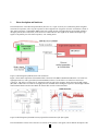
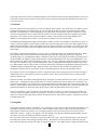
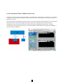
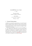
1 Short description and hardware The main functions of the Chiron Exposure Meter (from now on, "expm" for short) is to calculate the photon-weighted mean time for exposures, and to stop the exposures so that a targeted level of signal is collected. Its hardware consists of three main components - a Hamamatsu PMT which views a small amount of the light after the spectrograph collimator, through a pick-off mirror and a fiber, an electronics box which takes the drive signal for the shutter and outputs logic signals to the parallel port of the third component, a PC running Linux. Figure 1. Block-diagram of EM hardware and connections. Figure 1 shows main components of the EM and their connections. The PMT is Hamamatsu H9319-01. It is housed in a light-tight metal box, with a green filter (Chroma D545/80x) in front of it. The fiber is “scotched” into the box (no connector). The device is powered by 5V. Digitized counts are read by the computer, which also turns the high voltage (HV) ON or OFF. There is no built-in over-light protection, the PMT will be damaged if exposed to ambient light with HV ON! The EM software switches HV OFF if the detected flux exceeds a certain threshold. Figure 2. Block-diagram of the PMT circuits (left) and the transmission of the filter (right). This documentation consists of five sections: an overview of the system, a users guide, a more detailed description of the 2 processing, details of the software, including descriptions of the interfaces between expm components and those to the rest of the Chiron system, and an estimate of the sensitivity of the system (and an appendix with miscellaneous details not yet woven into the text). 2. Overview The drive signal for the Chiron shutter goes true for the duration of the exposure - the "shutter logic box" makes a positive going pulse at both edges of the shutter signal in order to trigger the parallel port, and also passes the signal to another input line of the parallel port so that the program can sense the polarity of the transition. The Linux system has a custom version for the parallel port driver, which records the system clock in the interrupt routine that is triggered by the shutter edge pulses. The software consists of the main handler ("expmsrv") which reads from the expm hardware, and a number of client programs which connect to a socket server in expmsrv to get access to the data. The Hamamatsu PMT digitizes the light level and outputs a stream of counts to the serial port of the Linux box, with 0.1s cadence. The main program contains a tight loop which uses a non-blocking read to look for the current sample from the PMT; when the read returns a sample the program assigns the current system time to that sample. Since there can be some latency in this time assignment, the times assigned to the serial samples are likely not as accurate as those assigned to the shutter edges. The expmsrv program must be installed to run as root, since it must directly attach to the parallel and serial ports. When the program is started, it initializes the PMT, including turning on the high voltage (HV), and starts looking at the incoming samples. If a programmable number of samples consecutively exceeds a threshold, the HV will be tripped off to protect the PMT. The expmsrv program opens three files, with timestamp names (in the form yyyymmddhhmmss). The arriving samples are binned and are continuously written to the ".cnts" file. Information about each exposure is written to the ".log" file. In addition, copies of the information that is sent for populating the FITS headers is written to the ".fitinf" file. When expmsrv detects a shutter open, it records the opening time, and begins accumulating the information needed to calculate the photon-weighted mean time. When the shutter close is detected, the calculations are performed, the information is written to the log, and the info needed for the FITS headers are written to the appropriate output. The expmsrv looks for client programs to connect to a particular socket. Upon connecting, each client sends an integer to indicate which one of several types of connections it wishes to make. These mostly have the sense of being an output stream for expmsrv data. There are two main clients which should probably always be running, in normal production use of Chiron. The first is the "FITS client" – it requests the stream of FITS values. As expmsrv calculates the exposure values, and writes them to the log file and the fitinf file, it also outputs them to all clients that asked for the FITS stream. This client takes the stream, and sends it to Chiron database system, which is interrogated during the writing of the FITS header. If the exposure meter has populated the database, the values will appear (if the system is down, the FITS header values will be zeroes). The second "production" client is called the "early termination client". It listens on a socket for target count values, and receives a stream of integrated counts from the expmsrv. If it has been sent a target count, it will calculate for the current increase in counts when the target will be reached, and send the Chiron control system a request to terminate the exposure at the appropriate time. 3. User guide The expmsrv computer is named "expmeter60". We are working on some cron jobs which will kill and start expmsrv, and the FITS and early term clients at noon every day. We'll also place here the name of scripts to kill and restart the three main programs. (If there are problems, do a "ps aux|grep exp|more" and look for the process ids for processes whose names start "expmsrv", "expfits", and "expterm", and "kill -SIGINT" those processes (SIGINT rather than KILL because the expmsrv can detect the interrupt and shutdown the HV cleanly.)) One of the other utility clients is the status GUI; the name starts with "expst". This GUI has an indicator at the top for the HV status, three lines for status messages, and three buttons. The indicator can show as blue for "unknown" (only just after status client has been started), red for HV off, and green for HV on. The "update" button will ping the expmsrv main 3 and update the indicator. The HV ON and HV OFF buttons are self-explanatory. (The button labelled "rebase" is not operational (yet).) The main purpose for this GUI is to detect whether the safety check has tripped off the PMT HV, and to provide manual control of the HV (for instance if the system is going to be worked on). (Possibly these functions should just be added into the Chiron control GUI, rather than requiring this separate client to be running). Another utility client can plot the light curve from the PMT. Its name starts with "expplt", and it has 4 input boxes to set the limits of the plot and a button to choose to plot the log of the intensities. This display is currently mainly for debug use, as it replots all the points upon the arrival of each new sample, and cannot keep up with a small bin size or many points in the plot. (We hope to write a better plot client some day). (A description of the photon weighted mean time calculations and FITS variable contents might be placed here; in the interim, an examination of the source code will probably serve to provide details of these calculations and interfaces.) 4. Software details Both the main and some of the clients look for an environment variable named EXPMPFDIR which tells them where to find the parameter files for setting various things. (When this was written, the env var is set at login time to point to /home/expmeter/EXPPFFILES. The .cshrc also sets two other environment variables; LD_LIBRARY_PATH which is loaded with a library that the clients need, and EXPMHOST which tells the clients where to look for the expmsrv main.) The pf (parameter file) for the expmsrv is named "expm.pf"; here is the current contents: [expmeter@expmeter ~/EXPPFFILES]$ more expm.pf 2000 //port_num 10 //num_pmt_samples /* must correspond to value on P cmd sent to PMT */ 20 //binning_size 0 //ser_time_offset 10 //avg_size 10000000 //threshold 10 //thresh_cntr_max The first one ("port num") is the port on which expmsrv will start listening for connections from clients. The second ("num_pmt_samples") is probably not being used at the moment (this should be remedied in a future software revision). The PMT intrinsically samples at 10 ms intervals, and a command sent at startup has it do some binning. Having this set to 10 means the program is receiving binned samples every 0.1 seconds. The third ("binning_size") is the additional binning used for the samples logged to the .cnts file, and sent to the plot client. 20 corresponds to 2 second bins. The fourth ("ser_time_offset") could be used to remove a skew from the serial sample time assignments. Currently I do not know what value this should have, and leave it at zero. The fifth ("avg_size" is how many bins are combined to form the averages used to estimate the pre- and post-exposure backgrounds. The sixth ("threshold") and seventh ("thresh_cntr_max") are used for tripping off the HV - in this example, 10 consecutive samples exceeding 10 million counts will shut the HV off. Here is the contents of the expfits4.pf file: [expmeter@expmeter ~/EXPPFFILES]$ more expfits4.pf ctioe1.ctio.noao.edu 5415 These items are merely the address and port number of where to make the socket connection for sending the database commands to set the values of the FITS header values. This program also reads files named add_keys and del_keys from the current directory (not yet the pf directory - this should probably be fixed). Here are their current contents: [expmeter@expmeter ~/EXPFITS4]$ more add_keys dbs set _queue_ em_timopn 0 STR dbs set _queue_ em_timcls 0 STR dbs set _queue_ em_numsmp 0 I32 4 dbs set _queue_ em_avg 0.0 FLOAT dbs set _queue_ em_avgsq 0.0 FLOAT dbs set _queue_ em_prdsum 0.0 FLOAT dbs set _queue_ em_netint 0.0 FLOAT dbs set _queue_ em_mnwob 0 STR dbs set _queue_ em_mnwb 0 STR fits key add emtimopn 'dbs em_timopn' //shutter open time from exposure meter __ AFTER__ __IFNDEF__ 0000-00-00T00:00:00.000 fits key add emtimcls 'dbs em_timcls' //shutter close time from exposure meter _ _AFTER__ __IFNDEF__ 0000-00-00T00:00:00.000 fits key add emnumsmp 'dbs em_numsmp' //number of samples __AFTER__ __IFNDEF__ 0 fits key add emavg 'dbs em_avg' //average intensity __AFTER__ __IFNDEF__ 0.0 fits key add emavgsq 'dbs em_avgsq' //sum of squared intens __AFTER__ __IFNDEF__ 0.0 fits key add emprdsum 'dbs em_prdsum' //sum of products of intens and bin number __AFTER__ __IFNDEF__ 0.0 fits key add emnetint 'dbs em_netint' //net intensity after bckgrd subtraction _ _AFTER__ __IFNDEF__ 0.0 fits key add emmnwob 'dbs em_mnwob' //mean time without bckgrd subtraction __AFT ER__ __IFNDEF__ 0000-00-00T00:00:00.000 fits key add emmnwb 'dbs em_mnwb' //mean time with bckgrd subtraction __AFTER__ __IFNDEF__ 0000-00-00T00:00:00.000 dbs flush em_timopn dbs flush em_timcls dbs flush em_numsmp dbs flush em_avg dbs flush em_avgsq dbs flush em_prdsum dbs flush em_netint dbs flush em_mnwob dbs flush em_mnwb The contents of the add_keys file is sent to the database server when the program is started, to prepare the system to deal with the FITS variables when they are set. [expmeter@expmeter ~/EXPFITS4]$ more del_keys dbs delete em_timopn dbs delete em_timcls dbs delete em_numsmp dbs delete em_avg dbs delete em_avgsq dbs delete em_prdsum dbs delete em_netint dbs delete em_mnwob dbs delete em_mnwb fits key delete emtimopn fits key delete emtimcls fits key delete emnumsmp fits key delete emavg fits key delete emavgsq fits key delete emprdsum fits key delete emnetint fits key delete emmnwob fits key delete emmnwb The del_keys file is (supposed to be) sent when the program exits cleanly, in order to cleanly remove the expmeter 5 variables from the FITS headers. (Currently the program apparently does not ever exit cleanly, so that the expmeter items stay in the headers, but with zero values). If desired, the del_keys file could be streamed into the database socket by hand if you want those items to not appear in the headers. Here is the current contents of the pf file for the early termination client: [expmeter@expmeter ~/EXPPFFILES]$ more exptermb1.pf 2110 ctioe1.ctio.noao.edu 5415 10 100 10 1000 The first parameter is the port number on which the client will listen for threshold setting commands. The second and third rows set the server and port number where the system will send the "set exposure time" commands to terminate the exposure. The fourth row sets a variable named "binsize"; this must correspond to the sampling being done in the PMT, and is used to know how to use the slope in sample number to predict an exposure time in seconds. The fifth row sets a variable named "rotbuf_size", (which is the dimensions of a internal rotating buffer) which is used to record the most recent samples in order to estimate the slope. The sixth row sets a variable named "delta_cnts"; this is the minimum number of counts that will be used to estimate a slope - for a bright source it may use the most recent two samples, but for a dimmer source it will go back through the buffer until it can find when the accumulated intensity was at least delta_cnts lower (this is in order to have a good SNR for the slope estimations). The seventh row set a variable named "emit_predict_time", which is how much in advance of the predicted threshold crossing time to start emitting exposure time updates. 5. Software interface details (still to be written - needs at least three parts: (1) description of how to connect to the expmsrv port, and of the various types of data streams (2) description of commands sent to the expterm client (3) descriptions of expst commands (update, hv_on, hv_off) and of the returned status messages) Also needs a description of format of the .cnts file (and of the .fitinf file?) Until this is written, reading the source code will be the best way to find these details) Computer requirements: The current generation of the h/w requires a Linux computer with a serial and parallel port. The parallel port interface was chosen as an inexpensive way to get an interrupt tied to an external logic signal (and with a second input available to detect current shutter signal level status). As this legacy interface is vanishing from modern motherboards, we might want to consider other options; for instance, just obtaining the shutter transition times from the Torrent. (Another option would be to get two GPIO inputs some other way; there are inexpensive PCI cards, and embedded Linux system boards (Raspberry Pi; BeagleBone Black) w/ GPIO pins (though would need CMOS instead of TTL levels). The custom parallel port driver is a modification of the “ppdev” driver supplied with the 2.6.32 Linux kernel. We have used Scientific Linux 6 and a CentOS distribution – both of these systems are redistributed versions of the Red Hat Enterprise Linux 6 system. The ppdev interrupt routine was modified to place the state of the shutter level signal and the time into a ring buffer when the interrupt is triggered by the signals generated at the shutter signal edges. A new ioctl (PPGETINTTIME) was added to the driver to be used in the main to fetch entries from the ring buffer. This modified driver is in the directory rpmbuild/BUILD/kernel-2.6.32-431.el6/linux-2.6.32-431.el6.i686/drivers/char/ppdev in the expmeter user’s home directory. A new kernel (and modules) is created by doing a “make; make install; make modules_install” series of commands. The /boot/grub/grub.conf file is then modified to point to the new kernel. 6 Exposure meeting sensitivity: (probably just a copy of Julien's memo with the calcs, or a pointer to that memo and info from power meter measurements during the re-commisioning.) Miscellaneous facts not yet woven into text: Another part of the hardware is a 5 volt power supply for the Hamamatsu PMT. The 5 volts is connected through a 4 pin circular Tyco connector. The positive voltage lead first passes through a loop (blue wire) on the PMT side of the connector before being sent to the PMT - this was to allow for the future installation of a safety switch, for instance on the Chiron lid, to shut off the PMT power when opening the spectrometer, The shutter logic box has three connections; a three pin Lemo connector that receives a copy of the Chiron shutter signal (third wire is for power for an optical isolator), a DB-25 connector that delivers the signals to the parallel port, and a USB connector, which is just used to deliver 5 volt power to the circuitry inside the box. (Insert circuit diagram and PCB board layouts here). This document does not cover the EM optics inside CHIRON that directs part of the light into EM fiber. See Section 3.7 and Figure 14 in the Instrument Description document, http://www.ctio.noao.edu/noao/sites/default/files/telescopes/smarts/tele15/chiron_0.pdf 7 6. Notes on Exposure Meter, CHIRON software side The Chiron software connects to the Exposure Meter as yet another client. It generates two connections, one is for sending commands to the expm (threshold, request/set for HV value) and another to receive PM data, used mainly to Real time graph for the observer On the other hand, the exposure meter software connects to the torrent acquisition software (panview), to set the keywords that will be written to the fits header images. The keywords are the ones explained section 4 of this document. The figure below shows the general architecture, and the Chiron Plug-In that graphs the PM data. For a complete documentation (and details) on this please refer to document CHI60S-2.6 (Chiron software description) and CHI60S-1.3 (Chiron software User Manual). 8