1
Exposure meeting sensitivity:
(probably just a copy of Julien's memo with the calcs, or a pointer to that memo and info from power meter measurements
during the re-commisioning.)
Miscellaneous facts not yet woven into text:
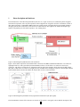
Another part of the hardware is a 5 volt power supply for the Hamamatsu PMT. The 5 volts is connected through a 4 pin
circular Tyco connector. The positive voltage lead first passes through a loop (blue wire) on the PMT side of the
connector before being sent to the PMT - this was to allow for the future installation of a safety switch, for instance on the
Chiron lid, to shut off the PMT power when opening the spectrometer,
The shutter logic box has three connections; a three pin Lemo connector that receives a copy of the Chiron shutter signal
(third wire is for power for an optical isolator), a DB-25 connector that delivers the signals to the parallel port, and a USB
connector, which is just used to deliver 5 volt power to the circuitry inside the box. (Insert circuit diagram and PCB board
layouts here).
This document does not cover the EM optics inside CHIRON that directs part of the light into EM fiber. See Section 3.7
and Figure 14 in the Instrument Description document,
http://www.ctio.noao.edu/noao/sites/default/files/telescopes/smarts/tele15/chiron_0.pdf
7