1
IP0011-12 Installation Procedure
Issue Date – 07/06/2012
Confidential
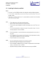
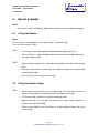
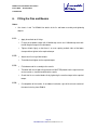
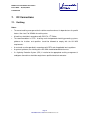
10. Fitting of Rotor and Nose Cone
Notes:
•
Lock the DC isolator in the OFF position while installing the rotor and nosecone.
•
See sheets 1 and 10 of SC0016 for the assembly method and tightening torques for the
rotor.
•
Do not install the rotor and nosecone until all of the electrical connections and tests are
completed and signed off.
With the brake released, the rotor can spin-up freely and may generate up to 400V across the DC
lines. This can present a safety risk during connection as well as a risk of equipment damage if
the lines are shorted.
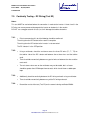
10.1.1.
•
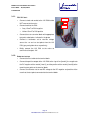
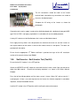
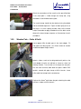
Place the key into the slot on the shaft of the nacelle and tap it into place gently.
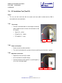
•
Lift the rotor on to the shaft (make sure the taper of the hole on the shaft adapter
matches the taper of the shaft) and push into place.
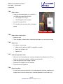
•
Fit the M30 washer and Staytite nut and tighten to the torque shown on sheet 1 of
SC0016.
•
Once the Staytite nut has been tightened to the required torque check that the key
cannot be seen protruding from the nacelle side of the rotor and that the rotor is
securely mounted on the shaft.
10.1.2.
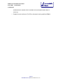
•
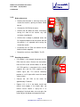
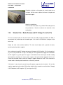
Fit the nose cone by clipping it over the front of the rotor.
•
Excessive force will break the clips; it should be gently pushed over the roots of the
blades.
10.1.3.
•
Sign off the rotor installation section of the commissioning sheet ID0019.
Page 32
Renewable Devices Ltd: www.renewabledevices.com