1
SONIC SOLUTIONS
SonicStudio 5
NoNOISE
(NN-101)
©1996 Sonic Solutions. All rights reserved.
SonicStudio 5, NoNOISE (NN-101)
This manual, as well as the software described in it, is furnished under license and may only be used or copied
in accordance with the terms of such license. The information in this manual is furnished for informational use
only, is subject to change without notice, and should not be construed as a commitment by Sonic Solutions.
Sonic Solutions assumes no responsibility or liability for any errors or inaccuracies that may appear in this
book.
Except as permitted by such license, no part of this publication may be reproduced, stored in a retrieval system,
or transmitted, in any form or by any means, electronic, mechanical, recording, or otherwise, without the prior
written permission of Sonic Solutions.
SONIC SOLUTIONS, INC. ("SONIC") MAKES NO WARRANTIES, EXPRESS OR IMPLIED, INCLUDING
WITHOUT LIMITATION THE IMPLIED WARRANTIES OF MERCHANTABILITY AND FITNESS FOR A
PARTICULAR PURPOSE, REGARDING THE APPLE SOFTWARE. SONIC DOES NOT WARRANT,
GUARANTEE, OR MAKE ANY REPRESENTATIONS REGARDING THE USE OR THE RESULTS OF THE
USE OF THE SONIC SOFTWARE IN TERMS OF ITS CORRECTNESS, ACCURACY, RELIABILITY,
CURRENTNESS, OR OTHERWISE. THE ENTIRE RISK AS TO THE RESULTS AND PERFORMANCE OF THE
SONIC SOFTWARE IS ASSUMED BY YOU. THE EXCLUSION OF IMPLIED WARRANTIES IS NOT
PERMITTED BY SOME STATES. THE ABOVE EXCLUSION MAY NOT APPLY TO YOU.
IN NO EVENT WILL SONIC, ITS DIRECTORS, OFFICERS, EMPLOYEES, OR AGENTS BY LIABLE TO YOU
FOR ANY CONSEQUENTIAL, INCIDENTAL, OR INDIRECT DAMAGES (INCLUDING DAMAGES FOR
LOSS OF BUSINESS PROFITS, BUSINESS INTERRUPTION, LOSS OF BUSINESS INFORMATION, AND THE
LIKE) ARISING OUT OF THE USE OR INABILITY TO USE THE APPLE SOFTWARE EVEN IF SONIC HAS
BEEN ADVISED OF THE POSSIBILITY OF SUCH DAMAGES. BECAUSE SOME STATES DO NOT ALLOW
THE EXCLUSION OR LIMITATION OF LIABILITY FOR CONSEQUENTIAL OR INCIDENTAL DAMAGES,
THE ABOVE LIMITATIONS MAY NOT APPLY TO YOU.
Sonic, Sonic Solutions, SonicStudio, the Sonic logo, Audio 2000, Sonic DVD Creator, DVD Production Alliance,
DVD Ready, DVD Toolmakers Guild, High-Density Audio, TimeTwist, Varispeed, MediaNet, and SonicOMF
are trademarks of Sonic Solutions.
NoNOISE is a registered trademark of Sonic Solutions.
Dolby Digital is a trademark of Dolby Laboratories, Inc.
QuicKeys is a registered trademark of CE Software, Inc.
JL Cooper is a registered trademark of J. L. Cooper Electronics, Inc.
Apple, the Apple logo, Finder, Macintosh, Quadra, and Quicktime are registered trademarks of Apple
Computer, Inc.
Acrobat is a trademark of Adobe Systems, Inc.
NuBus is a trademark of Texas Instruments.
All other company or product names are either trademarks or registered trademarks of their respective owners.
Written and designed at Sonic Solutions, 101 Rowland Blvd., Novato, CA. 94945, USA
Printed in the USA
Sonic Part Number 820037A (12/96)
Contents
1
SYSTEM OVERVIEW
NoNOISE Tools . . . . . . . . . . . . . . . . . . . . . . . . . . . . . . . . . . . . . . . . . . . . 1-2
Hardware Requirements . . . . . . . . . . . . . . . . . . . . . . . . . . . . . . . . . . . . 1-5
The NoNOISE Menu . . . . . . . . . . . . . . . . . . . . . . . . . . . . . . . . . . . . . . . . 1-7
A Typical NoNOISE Session . . . . . . . . . . . . . . . . . . . . . . . . . . . . . . . . . 1-7
2
COMPLEX FILTERING
How To Use the Complex Filters . . . . . . . . . . . . . . . . . . . . . . . . . . . . . . 2-1
Signal Analysis . . . . . . . . . . . . . . . . . . . . . . . . . . . . . . . . . . . . . . . . . . . . 2-2
Creating the Filter List . . . . . . . . . . . . . . . . . . . . . . . . . . . . . . . . . . . . . . 2-8
Applying Filters to a Sound file . . . . . . . . . . . . . . . . . . . . . . . . . . . . . . 2-12
Filter Types and Parameters . . . . . . . . . . . . . . . . . . . . . . . . . . . . . . . . 2-14
3
MANUAL DECLICKING (NN-101)
The NoNOISE Menu . . . . . . . . . . . . . . . . . . . . . . . . . . . . . . . . . . . . . . . . 3-1
Interpolation Gates Command. . . . . . . . . . . . . . . . . . . . . . . . . . . . . . . 3-2
Removing Clicks . . . . . . . . . . . . . . . . . . . . . . . . . . . . . . . . . . . . . . . . . . . 3-3
Interpolation Algorithms . . . . . . . . . . . . . . . . . . . . . . . . . . . . . . . . . . . . 3-5
Strategies for Isolating and Identifying Clicks . . . . . . . . . . . . . . . . . . 3-8
SonicStudio Version 5
iii
NoNoise
Summary . . . . . . . . . . . . . . . . . . . . . . . . . . . . . . . . . . . . . . . . . . . . . . . . 3-11
4
PRODUCTION DECLICKING
Declick Commands . . . . . . . . . . . . . . . . . . . . . . . . . . . . . . . . . . . . . . . . 4-2
Processing Long Files . . . . . . . . . . . . . . . . . . . . . . . . . . . . . . . . . . . . . . . 4-3
Generating the Click List . . . . . . . . . . . . . . . . . . . . . . . . . . . . . . . . . . . . 4-4
Click Correction . . . . . . . . . . . . . . . . . . . . . . . . . . . . . . . . . . . . . . . . . . 4-13
Interpreting and Editing the Click List. . . . . . . . . . . . . . . . . . . . . . . . 4-21
5
DECRACKLING
Using the Decrackler . . . . . . . . . . . . . . . . . . . . . . . . . . . . . . . . . . . . . . .
Launching a Decrackle Pass . . . . . . . . . . . . . . . . . . . . . . . . . . . . . . . . .
Input and Output Specification. . . . . . . . . . . . . . . . . . . . . . . . . . . . . . .
Processing Parameters . . . . . . . . . . . . . . . . . . . . . . . . . . . . . . . . . . . . . .
Removing Peak Distortion . . . . . . . . . . . . . . . . . . . . . . . . . . . . . . . . . .
6
5-2
5-2
5-5
5-5
5-8
BROADBAND DENOISING
The Denoising Process . . . . . . . . . . . . . . . . . . . . . . . . . . . . . . . . . . . . . . 6-2
The Noise Estimate . . . . . . . . . . . . . . . . . . . . . . . . . . . . . . . . . . . . . . . . . 6-3
Realtime Denoising . . . . . . . . . . . . . . . . . . . . . . . . . . . . . . . . . . . . . . . 6-13
Denoise Parameters . . . . . . . . . . . . . . . . . . . . . . . . . . . . . . . . . . . . . . . 6-17
Background Denoising . . . . . . . . . . . . . . . . . . . . . . . . . . . . . . . . . . . . 6-22
iv
SonicStudio Version 5
1
System Overview
NoNOISE is the world’s premier tool for restoration of vintage and
problematic audio recordings.
NoNOISE’s advanced real-time and out-of-real-time processes isolate
and eliminate audio artifacts such as hiss, scratches, hum, mechanical
and impulsive noise.
NoNOISE uses the power of the Sonic System, an advanced modular
audio workstation that also provides comprehensive editing and
mastering capabilities.
NoNOISE is not a single process or software module, but a set of
powerful tools to remove bothersome noise without damage to audio
program.
NoNOISE is applicable to restoration of old recordings, removing
unwanted noises from field recordings, and repairing audio materials
that have suffered damage.
SonicStudio Version 5
1-1
Getting Started
NoNOISE Tools
Audio artifacts come in many types, and every restoration job is unique.
NoNOISE consists of a group of linked tools for analysis and processing.
In using NoNOISE, you will apply your listening skills and knowledge
to determine how the individual tools may be applied to achieve the
desired results.
FFT Analysis
The Frequency Analysis (Fourier transform, or FFT) is a primary tool of
analysis for NoNOISE projects. The Fourier transform converts time
domain information into the frequency domain where it can be used to
pinpoint the center frequency of a hum component or to examine noise
and signal bandwidth.
Manual Declicking
In Manual declicking, you identify audio clicks and glitches by listening,
then locating them precisely using the Sonic System’s graphic waveform
display. Once a click or glitch is identified and marked, you can use any
one of several interpolation algorithms to resynthesize and replace
damaged audio with a seamless reconstruction of the original program.
Manual declicking is most useful when source material contains a
relatively small number of prominent clicks or glitches.
Complex Filtering
You can attack discretely pitched and steady-state noises such as hum
and buzz using filtering techniques. Complex filtering applies up to 512
high-precision digital filters to surgically remove the fundamental and
all harmonics of a contaminating noise.
Complex filtering can be used to clean up production dialog, live concert
recordings, telephone conversations and other situations with complex
pitched or band-localized noise components.
1-2
SonicStudio Version 5
System Overview
The system performs the designated processing out of real-time, creating
a new sound file as output. Processing is performed in the background,
so that you can process and edit simultaneously.
Production Declicking
Analog disc records contain far too many scratches and clicks to identify
and correct by hand. Production Declicking automates the process,
correcting hundreds or even thousands of clicks in a single pass.
Declicking is a two-stage process. First, use the Click Detect tool to
identify the locations of clicks and scratches, with variable parameters
that determine how the system will distinguish clicks and scratches from
program audio. This process produces a Click List that is used for actual
click removal.
After click detection, the source file waveform is displayed with colored
bars to indicate click sites . You may add, change, or remove these sites to
ensure proper removal of all audio glitches.
Once the Click List is prepared, a declick pass is performed to correct the
marked areas. As in the detect pass, you specify the parameters that
determine how the system replaces detected clicks with new audio.
Decrackling
In many cases impulsive noises are so dense that they are no longer
heard as individual clicks. These high-density impulses are perceived as
surface scratch, or crackle. The Decrackling tool removes this highdensity impulse noise.
Decrackling runs as a single-stage (no detect pass) background process
that produces a new sound file, leaving the original file untouched. As
with other NoNOISE processes, the operator controls the degree and
quality of decrackling applied.
SonicStudio Version 5
1-3
Getting Started
The Decrackler can also be used to correct many types of peak
distortion. By specifying an Amplitude Weighting factor, you can direct
the decrackle process to concentrate waveform reconstruction on signal
peaks, using undistorted sections between peaks to provide the spectral
information required for reconstruction.
Broadband Denoising
Denoising begins with analysis of the background noise to produce a
Noise Estimate indicating noise level versus frequency. This estimate is
used to set up the denoiser, specifying a threshold for downward
expansion in each of over 2,000 individual frequency bins. The Denoiser
then analyzes the source audio and reduces gain only at those
frequencies where the signal level falls below a designated threshold
between signal and noise floor in that band.
Denoising can run in real time or as a background process. The
advantage of real time processing is that it provides instant feedback on
parameter settings. You may wish to use real-time processing to
determine optimal parameter settings, and then use the non-real-time
processing to create an output file.
1-4
SonicStudio Version 5
System Overview
Hardware Requirements
All NoNOISE processing tools (except Manual Declicking) require one
or two Sonic NoNOISE Processor Boards. NoNOISE works in
conjunction with the either USP or SSP-3 board. For SSP-based systems,
model NN-102 is used, whereas USP-based system require model NN107.
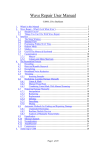
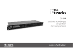
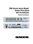
SCSI Slave (NoNoise Processor)
Main System Board
TOP
VIEW
I/O Connector Board
(SSP-3 only)
Macintosh
Rear Panel
Remove SCSI terminator
from Main board
a
b
c
NuBus slots
The NoNOISE co-processing board is installed next to the Main board in
a SCSI Slave configuration, joining the SCSI connectors of each board by
a common ribbon cable. The onboard terminator is removed from the
next-to-last board in the chain.
Note – The SCSI terminator must be removed from the board at the
center of the group. The Sonic System will not operate properly if there
is more than one terminator at the end of the SCSI bus. This is referred to
as double termination.
SonicStudio Version 5
1-5
Getting Started
The NN-102/107 board is installed in the same way as the system main
board. For installation, it is best to install the boards in a left-to-right
sequence, attaching ribbon cables to each board as it is installed to avoid
running out of room to attach the cables.
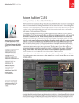
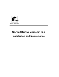
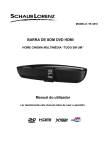
Stereo RTDN board
SCSI Slave
Main System Board
I/O Connector Board
(SSP-3)
Macintosh
Rear Panel
Remove SCSI terminator
from Main board and first
denoise board
a
b
c
NuBus slots
For faster stereo processing, an additional denoising board must be
added. This board is connected to the same SCSI bus as the main audio
board and the first denoise board. The board-board ribbon cables are
connected between all three boards as shown above.
Installation of NoNOISE cards is the same for SSP and USP cards, except
that the SSP-3 uses a separate I/O Connector board to route SCSI to
external sound -storage disks while the USP uses a direct cable
connection. Thus, USP-based systems require one less NuBus slot.
1-6
SonicStudio Version 5
System Overview
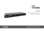
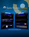
The NoNOISE Menu
The NoNOISE menu in the Sonic System’s main menu bar controls all
NoNOISE operations.
Manual
Declicking
Create and modify
Noise Estimates
Complex
Filtering
Broadband
Denoising
Production
Declicking and
Decrackling
Edit Click Lists
Available commands are shown in black, while commands that are
inactive appear in gray.
A Typical NoNOISE Session
NoNOISE is used in many different ways, In most cases, the overall
process remains the same. Source materials are loaded onto the Sonic
System sound disks, where they are analyzed and processed. The
processed audio is assembled using the Sonic System’s random-access
editing tools, then transferred to the medium of delivery.
In analysis and processing, you may choose any combination of
NoNOISE tools. In some cases, a single function such as Broadband
Denoising will provide the desired restoration. In other cases, there may
be multiple noise problems, requiring the use of multiple NoNOISE
SonicStudio Version 5
1-7
Getting Started
processes. Many common subjects of restoration, including aged
phonograph records, include hums, rumbles, scratches, crackles, and
hiss. These may require treatment with all of the major NoNOISE tools.
Every audio situation is unique and there is often more than one way to
approach the same problem. But many situations follow a common
pattern and can be addressed by a common procedure. Depending on
the material and the results desired, you may omit some processing
steps or elect to change the order in which they are used.
1. Load source materials onto the sound disks, as described in the
Installation and Reference manual.
2. Listen carefully to the source materials to determine the processing
functions to be used. Frequency Analysis may be used to identify
and isolate pitched components.
3. Apply Complex Filters first to remove steady noises such as hum
and turntable rumble, or unpitched noises outside the range of
signal.
4. Remove any large, broad (10-40 millisecond) audio glitches using
Manual Declicking.
5. After filtering and removal of large clicks, perform a click detect
pass to produce a list of the clicks to be attacked by automatic
declicking. Edit this list, if necessary.
6. Perform a background Declick pass to remove clicks and scratches.
7. Use Manual Declicking again to remove any prominent glitches
missed by the Detect and Declick passes.
8. In some cases, multiple Detect/Declick passes may be required.
9. If any intrusive clicks or glitches remain, correct these using
Manual Declicking.
10. After Declicking, use the Decrackling tool to remove impulsive
noises too densely spaced to be attacked as individual clicks.
1-8
SonicStudio Version 5
System Overview
11. Identify a short section of pure, or nearly pure, noise without
signal. Analyze this section using the Noise Estimate function, then
save the estimate to disk.
12. Use the real-time Denoising option to adjust denoising parameters
interactively.
13. When suitable settings are found, save the settings to disk, then
launch background denoising to create a denoised file using the
same settings.
The product of the process is a sound file of restored audio that you can
edit, mix, equalize, and then transfer to your medium of delivery.
SonicStudio Version 5
1-9
Getting Started
1-10
SonicStudio Version 5
2
Complex Filtering
NoNOISE Complex Filtering can apply up to 512 separate filters in a
single processing pass. It operates out of real time in the background,
freeing up the foreground for other work.
Background filtering is useful for removing hums and buzzes. In some
cases, these problems may be attacked by using the real-time filters on
the Sonic System Mixing Desk. There are three advantages to Complex
Filtering:
•
•
•
Far more filters (up to 512) can be applied in a single pass. This is
especially useful when multiple notch filters are used to remove
fundamental and harmonics of a pitched noise (such as hum).
Aggressive, high-order filters can be used without running out of
DSP processing power.
Long files can be processed in the background, freeing up the Sonic
System for other work.
How To Use the Complex Filters
There are two steps in using the Complex Filters:
1. Enter a list of the filters and parameter settings and store this list as
a file.
SonicStudio Version 5
2-1
Getting Started
2. Perform the filter pass on the source audio file. This creates a new
sound file that contains the processed sound.
You must specify both the source audio file and the file of filter
settings to be used for the pass.
Signal Analysis
To set up the filters appropriately, you need information about the
source audio. Some of this information can be obtained by careful and
informed listening, but you are likely to need more precise information
to set the frequency parameters as needed.
The Sonic System’s Frequency Analysis tool provides a view of the audio
signal in the frequency domain, where you can isolate individual signal
components. You can determine the exact frequency of each component
from the frequency analysis display and use this to set a corresponding
filter.
To use the Frequency Analysis tool:
1. Create or open an Edit Decision List (EDL) on the Sonic System.
2. Open the file that you wish to process into a panel of the EDL.
3. Use the left and right gates and zoom functions to zero in on the
section of audio you wish to analyze.
Use sections of less than one second for analysis. Otherwise, the
analysis may take an inordinate amount of time to complete.
For hum and noise removal, it is usually best to analyze a section
where the desired signal is low or absent. This makes the components
of the offending noise more easily visible.
2-2
SonicStudio Version 5
Complex Filtering
4. From the DSP menu, select Do Frequency Analysis.
The Macintosh cursor then switches to its spinning form. At the end
of processing, the waveform panel changes to display the analysis of
the selected signal.
Left and Right gates
In the example above, an analysis is performed on the noise between
two phrases in a spoken word source. The resulting analysis shows
principally broadband noise, with a prominent peak in the upper
frequencies.
In the Frequency Analysis display, you can use the left and right gates to
zoom in and view a section of the display at a higher resolution.
Frequency Readout
SonicStudio Version 5
2-3
Getting Started
You can place the left or right gates at the position of a signal peak, and
read the frequency from the labels at the lower left and right of the
panel. You may use these values to set notch or other filters to remove
that particular frequency.
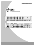
In the example above, the noise component around 15 kHz is obvious in
the full-scale display. Low- and mid-frequency information is less
evident, squeezed into the far left of the frequency scale.
To see what is happening in the lower frequencies, use the gates to zoom
in.
Low and Low-Mid
Frequencies
40Hz
Peak
60, 120, and
180 Hz Peaks
In the example above, frequency components are identifiable at 60 Hz
(line frequency) as well as at the harmonic frequencies of 120 and 180
Hz. These should be clearly audible as AC Hum, even though they are at
fairly low levels.
2-4
SonicStudio Version 5
Complex Filtering
However, another noise component is evident at around 40 Hz. This
component might not be heard as easily because it is near the edge of the
audible band and may be partially masked by the hum components. It is
likely to become more audible once the major hum components are
removed, so it is best to remove it at the same time.
Frequency Analysis Preferences
You may specify many of the details of the frequency analysis algorithm,
using the Frequency Analysis Preferences, selected from the Preference
command in the File menu.
PostScript error (undefinedresult, image
Transform Type
The default setting for Transform Type is DFT for “Discrete Fourier
Transform.” This is the familiar type of analysis, in which the results are
expressed in a frequency versus amplitude format.
Autocorrelation analysis is the inverse of the DFT. In this form, the
results are expressed in terms of the period of the component signals
rather than frequency. The full scale in which the periods are expressed
equals the length of the analyzed section (see below).
Cepstrum analysis is a more specialized form of signal analysis that is
sometimes used for speech work.
SonicStudio Version 5
2-5
Getting Started
Padding Technique and Transform Size
Frequency analysis works most quickly when analyzing a group of
samples whose number is a power of 2. The Transform Size provides a
selection of powers of two for use. The largest of these, 16384,
corresponds to about a third of a second at a sample rate of 48 kHz.
You may select one of these values, but it is more usual to choose the
option EXACT and then specify a method of padding. The system looks
at the area marked by the Gates, and then adjusts that to the closest
power of 2 (unless the option of No Padding is selected).
If Pad with Zeros is selected, the system will add zeros to the end of the
gated area to bring it up to the nearest greater power of 2 in size. If you
gate an area that matches a major pitch period of the signal viewed, this
results in an analysis that is easier to interpret.
The options to Grab More Data or Take Less Data cause the system to
alter the area of the waveform to fit the nearest power of 2 up or down,
much the same as selecting a fixed Transform Size.
The option of No Padding causes the analysis algorithm to run much
more slowly, but does not produce a correspondingly more accurate
result.
Windowing Function
To produce an accurate analysis on a finite number of data points, it is
necessary to apply a windowing function to compensate for the effects of
transition at each end of the analysis period.
The Sonic System provides three types of windows that are commonly
used for DSP. These three types, Hamming, Hanning, and Kaiser-Bessel,
are optimized for different aspects of the analysis.
DSP authorities continue to debate the relative merits of each window.
For the Sonic System user, it is much less important which window is
chosen than that some window be used. If the analysis is taken with
None selected under Window function, the resulting analysis will
continue numerous spurious frequency components.
2-6
SonicStudio Version 5
Complex Filtering
More information on windowing and analysis in general may be
obtained from the references listed at the end of this appendix.
Kaiser-Bessel Filter Parameters
This is a single parameter, that applies only to the Kaiser-Bessel type. It
defines a window function that applies to the analysis.
Recommended Settings
For purposes of analysis for Complex Filtering, the setting for the
Frequency Analysis are most often used in their default settings:
•
•
•
•
Transform Type = DFT (Discrete Fourier Transform)
Padding Technique = Pad with Zeros
Transform Size = Exact
Window Function = Hamming
The Filter Parameters are not active unless the Kaiser-Bessel window
type is selected.
SonicStudio Version 5
2-7
Getting Started
Creating the Filter List
Once you have determined the frequency components to be removed or
attenuated, you can create a list of filters and filter parameters for
processing. This list is known as the Filter Specification file.
To create a Filter Specification file:
2-8
SonicStudio Version 5
Complex Filtering
1. Select Set Filters... from the NoNOISE menu.
This opens the Background Filter Selection dialog, where you can
enter the specifications for the filters you wish to apply.
You can select filter types from the list displayed in the upper portion
of the dialog.
To add a filter to the Filter Specification file:
1. Select the desired filter type from the list by clicking on it with the
mouse.
SonicStudio Version 5
2-9
Getting Started
2. Click on the Add Filter button, or double-click on the desired filter
in the list of selections.
A filter of the type selected is added to the specification list.
Once you have added a filter to the list, you must specify the
parameter values that apply to that filter.
To set the values for a filter in the Filter Specification list:
1. Select the filter by clicking on its name in the list.
2. Click on the Set Values button, or double-click on the name of the
filter.
This opens a dialog listing the parameters that apply to the selected
filter.
Each filter type has specific parameters that apply, described later in
this chapter.
To enter a desired value for a filter parameter:
1. Select the entire field containing the value by double-clicking, or
dragging with the mouse.
2. Type in the desired value.
3. Press the Tab key to step to the next field.
2-10
SonicStudio Version 5
Complex Filtering
4. Once parameter values have been entered for the filter, click on the
OK button to return to the Filter Selection dialog.
Saving the Filter List
Once you have entered a set of filters and parameters into the filter list,
you must save the completed list to a file before you can use it to process
a sound file.
To save the completed list as a Filter Specification File:
1. Click on the Write button.
2. Assign a name for the file, or use the default that appears in the
Mac file select dialog.
3. Save the file.
Once you have entered and save the desired filter list, close the Filter
Specification dialog by clicking on the Cancel button.
Reading a Previously Saved File
Previously stored filter lists may be reopened and edited to change the
configuration of filters or the parameter values.
To read in a filter file list:
1. Open the Filter Specification dialog.
2. Click with the mouse on the Read button .
3. Select the file to be read in.
Once a filter list has been read in, you can alter it and save it to the
same or different file.
The ability to save filter settings is particularly useful for recurring
situations such as filter settings for odd, even, and all harmonics of
line hum.
SonicStudio Version 5
2-11
Getting Started
Applying Filters to a Sound file
After you create the Filter Specification file, you can apply that list of
filters to any audio data file by using the Filter... command. The
background filter process creates a new sound file by applying a filter
list file to an already existing sound file.
Select Input File.
Set Start/End Times
Name Output File
Select Filter
Specification File
To launch a background filter job:
1. Select the command Filter… from the NoNOISE menu.
2. Using the file select that appears, choose the audio data file you
wish to process.
The dialog Launch Filter Job appears.
3. Enter the name to be used for the output file resulting from filtering
and select the Filter Specification file to be used.
If both channels of a stereo sound file are being processed, the launch
dialog shows separate sections for each channel.
4. If you wish to process only a part of the file, set the Start and End
times with respect to the source sound file.
5. Set the Output Sound File name by clicking on <click here>.
A Mac file select dialog appears with the sound file name followed by
.filt as a default.
6. Select the Filter Spec file by clicking on <click here>.
A file select dialog appears. You may select any valid Filter Spec file.
7. Click on the Launch button.
2-12
SonicStudio Version 5
Complex Filtering
The dialog includes an option to delete the original file at the conclusion
of the background process. This facilitates multiple background jobs by
conserving space on the sound disk.
Delete Input should not be checked unless you are confident that the
results of processing will be as desired. The deleted sound file cannot be
recovered.
When you click the Launch button, the defined processing job is placed
into the Sonic System’s background queue. This is a list of tasks that the
system will perform in the order in which they are entered.
You can monitor the progress of a filter or other background process by
selecting Background Manager from the File menu’s Managers item.
While a background job is in processes, you can launch additional
processing jobs. These are placed in the background queue and may be
seen listed in the Waiting... box in the Background Manager. When the
current job completes, the system loads the next item in line for
processing.
SonicStudio Version 5
2-13
Getting Started
You can even specify the output file from a previous step as the source
file for the next processing stage. The Sonic system allocates file space at
the time of launching, so the output file’s name may be chosen from the
file select dialogs, even though the actual sound data does not yet exist.
Filter Types and Parameters
The filters available in the Complex Filtering module are the same as the
real-time filters provided for the Sonic System Extended Mixing Desk
(SS-201 option). Some of the terms used to refer to the filter types and
their variable parameters are different.
Center Frequency (cf)
The center frequency is the reference point of the filter. There are two
different interpretations of the center frequency in the Sonic System
Complex Filters, depending on the filter type used:
In filters that have a bandwidth or Q parameter, the center frequency
references the midpoint of the affected region. Usually the center
frequency is the most affected frequency of these types of filters.
Filter types that affect frequencies above or below a particular frequency
reference the center frequency (cutoff frequency) as the -3 dB point from
the boost or cut specified. A HiShelf filter designed to give a 6 dB boost
above a crossover frequency (center frequency) of 10 kHz would have a
boost of 3 dB at 10 kHz.
Bandwidth (bw) and Q
Bandwidth and Q are two different ways of specifying the width of the
filter. The width of the filter is measured from the -3 dB down points on
either side of the center frequency. Bandwidth represents this width in
absolute Hz. A bandwidth of 1000 means that the filter is 1000 Hz wide
between the -3 dB points.
2-14
SonicStudio Version 5
Complex Filtering
Q represents the width of the filter relative to the way that we hear. A Q
setting of 2 always has a half octave bandwidth regardless of the center
frequency. In mathematical terms, the Q is equal the center frequency
divided by the bandwidth.
Q = Center Frequency / Bandwidth
Also: Bandwidth = Center Frequency / Q
A Q of 1 = a one octave filter width. A Q of 2 = a half-octave filter width.
A Q of 4 = a quarter-octave filter width. A Q of 0.5 equals a 2 octave filter
width.
Boost/Cut
The boost/cut represents the maximum affect of the filter on the
program material. Boost/Cut is expressed in positive or negative
decibels (dB).
Order
The order of the filter sets the slope of the filter’s transition area. A first
order filter usually means that the filter has a transition slope of 6
dB/octave. Each increase in the order adds another 6 dB/octave to the
transition. Thus, a 3rd order filter would have a transition slope of 18
dB/octave, etc.
BandPass and BandStop filters require an even-numbered order. A
second order BandPass/BandStop has transition slopes of 6 dB/octave
and a fourth order BandPass/BandStop has transition slopes of 12
dB/octave.
StopRipple
StopRipple expresses how the filter affects audio in the stopband. The
interpretation of Stopband and Stopripple depends on the filter type.
SonicStudio Version 5
2-15
Getting Started
For HiPass, LowPass, BandPass and BandStop filters:
•
•
Stopband - the portion of audio eliminated or attenuated.
Stopripple - minimum attenuation in the stopband. A setting of -40
dB means the signal will be at least 40 dB down in the stopband.
For HighShelf, LowShelf, EHighShelf (Extended HighShelf), ELowShelf
(Extended LowShelf), Parametric, and EPara (Extended Parametric)
filters:
Stopband - the portion of audio that is to be unaffected by the filter.
Stopripple - the maximum change in dB as a result of the filter. A setting
of 0.5 dB means a maximum EQ alteration of 0.5 dB. 0.5 dB EQ change is
approximate minimum ripple audible by the human hear. The Sonic
Mixing desk defaults the stopripple to 0.1 dB.
PassRipple
Passripple expresses the effect of the filter on audio in the passband.
Passband has two interpretations in the Sonic System, depending on the
filter:
For HiPass, LowPass, BandPass and BandStop filters, Passband represents the portion of audio that the filter is letting pass through
unchanged. For HighShelf, LowShelf, EHighShelf (Extended HighShelf),
ELowShelf (Extended LowShelf), Parametric, and EPara (Extended
Parametric) filters, Passband - represents the portion of audio that is
affected by the filter. In all cases, passripple is the maximum change in
dB in the passband as a result of the filter. A setting of 0.5 dB means that
the stopband will have a maximum EQ alteration of 0.5 dB due to the
filter.
2-16
SonicStudio Version 5
Complex Filtering
Parametric Filter
The parametric (presence) filter boosts or attenuates a particular region
of the audio spectrum.
There are three parameters that define the response of the Parametric
filter type:
Center Frequency (cf)
The Center Frequency is the mid-point of the band affected. The
Parametric filter’s center frequency may be selected over a range of 1.0
Hz to 22.050 kHz
Bandwidth (bw)
The Parametric filter is a resonance-type filter. Its bandwidth in Hertz
may be translated to filter Q by the formula: Q = cf/bw.
Boost
Boost indicates the gain applied at the Center Frequency. The Parametric
filter can supply boost (cut) of ±24 dB.
SonicStudio Version 5
2-17
Getting Started
Extended Parametric (EPara) Filters
Extended Parametric filters provide flatter response in the boost/cut
region. A Parametric filter is a simple resonance, while an extended
presence filter has a flat region centered on the frequency that is boosted
or cut. The order, denoted by n=2 through 4, determines the slope of the
skirts or abruptness of the transitions.
Center Frequency (cf)
The mid-point of the band affected. The Parametric filter’s center
frequency may be selected over a range of 1.0 Hz to 22.050 kHz
Bandwidth (bw)
The Parametric filter is a resonance-type filter. Its bandwidth in Hertz
may be translated to filter Q by the formula: Q = cf/bw.
Boost
Boost indicates the amount of gain applied at the Center Frequency. The
Parametric filter can boost (cut) by ±24 dB.
Filter Order
The Order of a filter, corresponding to the value of n (1 to 4) in the filter
selected, controls the slope of the filter’s response curve. A first-order
filter has a slope of 6 dB per octave. Slope increases by 6 dB per octave
for each increment of 1 to the filter’s order.
StopRipple
The maximum change in dB in the stopband (the range boosted or cut).
A setting of 0.5 dB means a maximum EQ alteration of 0.5 dB due to the
filter.
2-18
SonicStudio Version 5
Complex Filtering
Notch Filter
The Notch filter is a special case of the Parametric filter, in which the
gain at the center frequency is set to minus infinity, effectively
eliminating all signal at that frequency.
Specifying a notch filter requires only two parameters: center frequency
and bandwidth. The gain at the center frequency of a notch filter is fixed
at -∞ dB, so that the center frequency is eliminated completely.
Center Frequency (cf)
The range of the Notch filter’s center frequency is the same as for other
filters on the Sonic system, from 0.1 Hz to 22.050 kHz.
Bandwidth (bw)
The Notch bandwidth is specified in Hertz, with a range from 1 Hz to 22
kHz.
High and Low Shelving Filters (HiShelf and LoShelf)
Shelving filters apply a fixed boost or cut to all frequencies beyond the
cutoff frequency. Shelving filters have two variable parameters. These
are different from those of Parametric filters.
SonicStudio Version 5
2-19
Getting Started
Cutoff Frequency (cf)
Cutoff Frequency is the point where the signal is boosted or cut by 3 dB,
or by 1/2 the specific boost/cut (if less than 3 dB).
Boost
Boost (or Cut) applies to signal above (in the case of HiShelf) or below
(in the case of LoShelf) the cutoff frequency. The range of boost or cut is
±24 dB.
Extended High and LowShelf Filters (EHighShelf and
ELowShelf)
By increasing the order of the filter, the sharpness of transition between
passband and stopband increases
The Extended Shelving filters have addition parameters for setting the
order of the filter as well as ripple in the response in the pass and
stopbands.
Filter Order (n)
The order of a filter, an integer from 1 to 4, determines the slope of the
filter’s response curve. A first-order filter has a slope of 6 dB per octave.
Slope increases by 6 dB per octave for each increment of 1 to the filter’s
order.
2-20
SonicStudio Version 5
Complex Filtering
PASSBAND RIPPLE (passripple)
In a Shelving filter, the passband is the portion of the signal affected
(boosted or cut) by the filter Passripple is the maximum change in dB in
the passband. A setting of 0.5 dB means that a maximum EQ boost or cut
in the stopband of 0.5 dB.
STOPBAND RIPPLE (stopripple)
The stopband is the portion of the signal not affected by the filter.
High-Pass and Low-Pass Filters (HiPass and LowPass)
The high-pass and low-pass filters operate in three regions: A passband
where signal is minimally altered; stopband where signal is attenuated;
and the transition band that separates the two.
In the passband, there is an amplitude fluctuation called passband
ripple. Generally, anything less than about 0.5 dB of ripple is inaudible.
Passband ripple defaults to 0.1 dB. There is also some variation in the
stopband, called stopband ripple. It represents the maximum value that
the filter gain attains in the stopband.
For a high pass filter, the frequency parameter refers to the highest
frequency at which the gain attains the minimum value in the passband.
A low pass filter has a gain of 1.0 (less the pass ripple) below ƒ, and falls
off smoothly to stop ripple at some point above ƒ.
Cutoff Frequency (cf)
The Cutoff Frequency is the frequency at which signal level is reduced
by 3 decibels. The range of cutoff frequencies for both high- and lowpass filters is from 1 Hz to 22.05 kHz.
SonicStudio Version 5
2-21
Getting Started
Filter Order (n)
Filter order, an integer from 1 to 4, controls the steepness of the
transition from stopband to passband. The transition band drops off by
roughly 6 dB per octave for each unit increase in order. The higher the
order, the greater the chance of audible ringing at the cutoff frequency.
Passband Ripple (passripple)
In the Low and Highpass filter, the Passband Ripple is the area that is
not affected by the filter.
Stopband Ripple (stopripple)
For Low and Highpass filters, the Stopband Ripple is the maximum gain
reached in the area after the cutoff frequency.
Utility Filters (DC, Emphasis, RIAA)
Complex Filters includes several types of utility filters for common
functions of DC removal, pre- and de-emphasis, and application or
removal of the RIAA curve for vinyl records.
These filters have no variable parameters. They are simply on or off
No DC
The No DC filter is a simple DC reject filter. The No DC filter provides 1
dB of cut at 34 Hz and 3 dB of cut at 18 Hz.
Emphasis and De-Emphasis
The Emphasis filter is a 15/50 microsecond curve, as defined as an
option for Compact Disc masters. The De-Emphasis filter provides for
removal of this high-frequency boost from material that is previously
emphasized.
2-22
SonicStudio Version 5
Complex Filtering
DC/De-Emphasis
No DC/De-Emphasis combines this with a filter to remove the Sony F1
(EIAJ digital audio adapter) 15/50 microsecond emphasis curve.
RIAA and De-RIAA
The Sonic system supports RIAA and De-RIAA filters. The RIAA filter
imposes the standard RIAA characteristic normally applied, in LP
mastering, at the input to a disk cutting lathe. The De-RIAA filter
removes the effect of a RIAA filter.
Band Pass and Band Stop Filters
Band Pass and Band Stop are like putting together a high pass and a low
pass filter. Band Pass allows only certain frequencies to be admitted and
rejects all others that are out of the range. Band Stop eliminates a certain
range of frequencies and passes all the rest.
Center Frequency (cf)
The range of the BandPass and BandStop filter’s center frequency is the
same as for other filters on the Sonic system, from 1 Hz to 22.050 kHz.
Bandwidth (bw)
Bandwidth is specified in Hertz, with a range from 1 Hz to 22 kHz.
Filter Order (n)
The order of a filter, an integer value from 1 to 4, determines the slope of
the filter’s response curve. A first-order filter has a slope of 6 dB per
octave. Slope increases by 6 dB per octave for each increment of 1 to the
filter’s order.
SonicStudio Version 5
2-23
Getting Started
PASSBAND RIPPLE (passripple)
In a Shelving filter, the passband is the portion of the signal affected
(boost or cut) by the filter Passripple is the maximum variation in dB in
the passband. A setting of 0.5 dB means a maximum EQ alteration of 0.5
dB due to the filter.
STOPBAND RIPPLE (stopripple)
The stopband is the portion of the signal not affected by the filter.
2-24
SonicStudio Version 5
3
Manual Declicking (NN-101)
The Manual Declicking option for SonicStudio™ is designed to assist in
removing unwanted intrusive noises such as clicks, pops, thumps, etc.
By following a simple procedure, you can replace such noises and
discontinuities in the audio waveform with continuous audio:
•
•
Use the Left and Right Gates to identify a (usually) short area of the
sound file containing an anomaly to be removed.
Use one of several interpolation algorithms selected from the system's
NoNOISE™ menu.
The algorithm analyzes audio on either side of the anomaly. Based on
this context information, the algorithm synthesizes replacement sound
for the anomaly.
The replacement sound is substituted for the original sound and the
original sound is stored in a special file (called a Restore File) from
which it can be retrieved if need be.
The NoNOISE Menu
The commands for removing (interpolating) clicks and other noises are
located in the NoNOISE menu in the main menu bar.
SonicStudio Version 5
3-1
Getting Started
Remove and
Restore Clicks
Unless other NoNOISE options are installed, the only commands active
in this menu are the ones associated with Manual Declicking.
Interpolation Gates Command
The command for removing clicks is Interpolate Gates, at the very top of
the menu. This command has a pull-left menu that lists several
selections.
3-2
SonicStudio Version 5
Manual Declicking (NN-101)
The process of removing a click or noise consists of identifying the
anomaly to be removed by placing the Left and Right Gates on either
side of the problem area in the waveform display. Once the section to be
replaced is so identified, the user selects one of the interpolation types
from the Interpolate Gates menu.
Once the interpolation algorithm is selected, the system performs a
frequency and phase analysis of the audio on either side of the glitch to
be removed. It then synthesizes a section of audio to interpolate
smoothly from the spectrum prior to the click to the spectrum following
the click.
Removing Clicks
The process of removing a click consists of identifying and marking the
anomaly in the waveform display, and then selecting an interpolation
algorithm from the NoNOISE menu.
Identification
1. On the waveform display, identify the location of the click or other
anomaly to be removed.
2. Zoom in until the area of the glitch fills a substantial part of the
display.
3. Place the Left and Right Gates around the area of the click.
Be careful to gate as narrowly as possible without leaving any part of
the anomaly outside the gates.
Clicks Gated prior to Interpolation
SonicStudio Version 5
3-3
Getting Started
Clicks scratches vary in length, with most between 1 and 15
milliseconds. Areas as long as 1/2 second can sometimes be interpolated
with good results, but the results in that case depend very much on the
audio context.
Note – Be sure that the click to be removed lies entirely between the Left
and Right Gates.
The Declicking interpolators use the area immediately outside the gates
to determine the spectrum of the synthesized replacement audio.
Because of this, poor results will be obtained if any part of the anomaly
is left outside the Left and Right Gates.
Removal
1. From the NoNOISE menu, select the Interpolate Gates command.
2. Choose an interpolator type from the pull-right menu that appears.
The five interpolator types available are A, B, C, D, and E. Details on
the use of each type are provided in a later section of this manual.
Restore Bar
Clicks after Interpolation
The interpolation algorithm analyzes the anomaly identified and
constructs replacement sound. After the replacement sound is inserted to
substitute for the anomaly, a red (gray on a B&W monitor) bar above the
waveform extending over the area that has been repaired. This “Restore
Bar” indicates that sound has been replaced in this area of the waveform.
3-4
SonicStudio Version 5
Manual Declicking (NN-101)
If the results produced by declicking are not acceptable, the original
sound may be restored using Restore Gates from the NoNOISE menu.
To restore a previously interpolated section of audio to its original state:
1. Place the gates around the Restore Bar left by the interpolation
2. Select the Restore Gates command from the NoNOISE menu.
The bar disappears and the original sound again appears in the
waveform.
Declicking operates on the original soundfile. If clicks are removed from
a sound segment in an edited schedule, the same Restore Bars will
appear anytime that sound file is opened or edited into other audio.
Interpolation Algorithms
There are several interpolators that are available in the NoNOISE
System. Each type is suited to a particular type of audio problem and
context.
The different types, A, B, etc., were designated in the order that they
were developed. However, this is not the order of most frequent use. The
submenu lists the interpolation types in approximate order of the
frequency of their use.
SonicStudio Version 5
3-5
Getting Started
Note – The B type interpolator is the most general. The majority of
declicking situations can be handled by simply choosing this first
selection.
Type B Interpolation
This is the most general-purpose of the declicking algorithms, and works
well on complex musical waveforms (for example, where several signals
are combined with instruments that produce non-periodic waveforms,
such as sax, strings, etc.).
The basic Type B interpolator examines the audio on either side of the
click to determine the context for resynthesizing audio to fill the gap. In
most situations this basic interpolator will produce the best results.
There are two variations of the command that load the context
information in a particular way. If, for example, a click occurs just prior
to the beginning of the attack of a piano note, the basic Type B
interpolator would include part of the piano note in its resynthesis,
producing the impression that the piano starts a bit early.
In this case, the B Type, L-> R variation, would avoid getting the piano
note into the interpolation. Likewise, the R->L variation might be used
in an instance where a click follows immediately after a sudden change
in the audio waveform.
Types A and C Interpolation
The Type A and Type C interpolators are waveform interpolators. A
waveform interpolator is most useful in dealing with periodic
waveforms, such as brass instruments or the human voice. The Type A
and C interpolators take context information from six periods (the
distance between successive peaks in the waveform) to the left and right
of the area identified by the Left and Right gates.
3-6
SonicStudio Version 5
Manual Declicking (NN-101)
Note that after interpolation, the Restore Bars extend for a short distance
outside the gated area. This is because the waveform interpolator
performs a short-duration crossfade of its results back into the original
sound. It is the area of the crossfade that extends beyond the Gate
positions.
The difference between these two types is that the Type C has
protections built into it for certain cases for which waveform
interpolation algorithm produces bad results. Type A lacks these
protections. The Type A interpolator will always produce an
interpolation, but the results may not always be pleasing. The C Type
interpolator will sometimes fail to interpolate the signal designated. (If
this occurs, the user should try a different interpolation algorithm.)
The variations on the basic Type C interpolator, marked C Type, L->R
and C Type, L<-R, provide control of the loading of context information
into the interpolator, emphasizing either the sound to the left, or sound
to the right of the gated sound.
Types D and E Interpolation
These are very high-order interpolation that may be used to correct
problems that elude other interpolation algorithms. Be warned however.
The process runs from about 1000 to 2500 times real-time. Both
interpolations use 80-bit precision arithmetic to produce very high
quality interpolation.
The Type D interpolation is only capable of replacing up to about 2
milliseconds (0.002 seconds) before it runs out of memory. The Type E
Interpolator provides a very similar algorithm that can be used on large
sections of audio.
If there is a particularly problematic area, then Type-E manual
interpolation (perhaps left to run overnight) can help clean up small
regions. As with the other interpolation algorithms, Type E operates
directly on the sound file, and it produces restore bars to show where
replacement has been performed.
SonicStudio Version 5
3-7
Getting Started
Strategies for Isolating and Identifying Clicks
Often, the most difficult part of declicking a cut is to locate the clicks to
interpolate. The interpolators included in the NoNOISE System are very
powerful, but they can be used only after the clicks have been found. In
only a small percentage of cases are the clicks in a recording easily
visible in the waveform itself.
One approach is to use the positions of the Gates and the Play To Gates
command to get a precise fix on the location of a click. Simply keep
moving the Left or Right Gate, and auditioning until the click is no
longer audible. Or use the Rock N Roll feature to scrub over the area of
the click. Once a small area has been identified, within which the click
must lie, Zoom into a resolution at which the click should become
visible.
In a recording with many clicks, this approach would be impractical.
Also, even with careful auditioning and Zooming, some clicks will evade
this type of search.
A useful technique is to use the SonicStudio’s filtering to emphasize the
clicks, and create a Detect File to identify clicks visually.
Creating a Click Detect File
Most clicks constitute a burst of energy across the audible spectrum, and
a high-pass filter will cause clicks to stand out in greater relief relative to
musical program.
This principle can be used to create a soundfile specially for detecting
clicks.
3-8
SonicStudio Version 5
Manual Declicking (NN-101)
Segment of Complex Waveform with
Synchronized Detect File
Likely position of Click
To create a Click Detect file:
1. Place the soundfile to be declicked in an Edit Decision List (EDL).
2. On the Mixing Desk, use a Hi Shelf or HiPass filter to emphasize
clicks and glitches.
3. When satisfied with the filtering, follow the directions in the system
User Manual to capture the output of the Mixing Desk in a new
soundfile.
4. Open the new soundfile in a different panel of the EDL. Make sure
it is synchronized with the original.
The clicks will be easily visible in the high-pass output.
The typical high-pass filter used to produce a Detect File for analog tape
recordings (or old disk recordings transferred to tape) is a first order
filter with high frequency of 12,000 Hz, or so, and Stop Ripple set at -40
dB.
SonicStudio Version 5
3-9
Getting Started
The same high pass filter may not be appropriate to create a detect file in
all circumstances. One recurring situation is declicking of optical clicks
occurring on old movie optical sound tracks. Since the original click or
dropout was band-limited, the resultant click does not have much high
frequency energy.
A lower cutoff frequency (and perhaps a higher order) may be needed to
focus the Detect File on the click energy between, say, 6,500 and 9,000
Hz. Unfortunately, much musical signal typically resides in this band.
That makes click detection in such files somewhat problematic.
Low Frequency Interference
Many older 78 RPM disk recordings are characterized by an abundance
of low-frequency energy. In some cases these low-frequency sounds
change quite rapidly and violently. The B Type interpolator has only a
small area of the soundfile in which accurately to identify the low
frequency components in a signal.
Because of this, there is some potential for error in the interpolation.
When this happens a characteristic artifact is sometimes inserted into the
soundfile. It sounds like a low level thump or thunk.
Under such circumstances, the best results usually are achieved when
the source soundfile is first filtered aggressively to roll off the low
frequency noise. Since the bandwidth of many older disk recordings was
severely limited to begin with, it is often possible to apply a 2d or 3d
order hi pass filter with a hi frequency as high as 50, 60 or even 70 Hz.
In addition to assisting the B Type interpolator, this procedure also has
the beneficial effect of removing much low frequency noise that is
annoying in its own right, such as hum, or turntable “rumble.”
Thumps, Dropouts, and Such
Although the bulk of anomalies removed using the NoNOISE System
are clicks, the interpolators may also be used to remove a variety of
other ills such as needle thumps, oxide dropouts, etc.
3-10
SonicStudio Version 5
Manual Declicking (NN-101)
In many of cases, the difficulty is not so much interpolating the
anomalies, but finding them. Dropouts can be viewed directly by
zooming in tight on the waveform display. For thumps, a Detect File
built on a low pass filter (for example, first order low pass at 100Hz) may
be useful.
Summary
The SonicStudio's Manual Declick option provides a powerful set of
tools to identify and correct clicks and other audible glitches embedded
in program audio. In the hands of a knowledgeable and experienced
operator, the Manual Declick tools can perform seeming miracles of sonic
restoration.
SonicStudio Version 5
3-11
Getting Started
3-12
SonicStudio Version 5
4
Production Declicking
Automatic Declicking detects and eliminate clicks automatically in two
steps. First, a click detect pass reads through the sound file and produces
a list with the location and description of each click. This click list
appears as marks on the waveform display, indicating the locations and
duration of each click.
The click list contains the sample number of every click found, the width
of the click in samples, the strength (amplitude) of the click, and other
information used by the declicking algorithm.
The click list is then used to guide the declick pass. The declick pass
makes corrections directly on the source sound file, maintaining a
separate hidden file of the original clicks, which can be used to undo any
portion of the declicking.
An automatic declicking session proceeds as follows:
1. Load source material onto the Sonic System sound disk.
2. Perform a click detect pass to identify clicks and pops to be
corrected.
Once the pass gets started, you can view the results on the first part of
the file and change the detection parameters if needed.
SonicStudio Version 5
4-1
Getting Started
3. Following click detect, read the click list into the waveform display,
and edit the list if necessary.
4. Perform a declick pass to remove the detected clicks.
5. For difficult material, it may be necessary to run additional detect
and declick passes.
6. Remove any clicks that remain using Manual Declicking.
Declick Commands
The NoNOISE menu includes two groups of commands for Automatic
Declicking.
Launch Detect
and Declick
Edit Click List
The first two commands launch the processes of detecting and
eliminating clicks. The second, longer group includes commands for
viewing and modifying the click list.
4-2
SonicStudio Version 5
Production Declicking
Mono and Stereo Declicking
Automatic declicking is entirely monaural, a restriction inherent in the
process. (Many materials for declicking are monaural as well, such as 78
RPM recordings from the 1930s.) Stereo declicking is performed by
declicking each channel separately.
Processing Long Files
Click detect and declick operate on an entire sound file at once, for
reasons having to do with the management of the click list in relation to
the sound file itself.
During click detect, the click list is held entirely in Macintosh RAM.
Long files produce correspondingly lengthy click lists. If the material has
a lot of clicks as well, memory overflow may result.
There are three ways to overcome or avoid this problem:
•
•
•
Load source materials as two or more shorter files. After processing,
use the Sonic System’s editing features to splice the files together.
Alter the detect parameters so that a smaller portion of clicks are
detected, then use multiple passes to eliminate all clicks.
Increase the amount of RAM available by assigning more RAM to the
SonicSystem application. (Select the SonicSystem icon from the Mac
Finder and type Command-I. This opens an information box that
includes a field for the amount of memory assigned.)
As larger blocks of RAM memory have become more affordable, the last
option is recommended.
SonicStudio Version 5
4-3
Getting Started
Generating the Click List
A click list is produced automatically by the click detect pass. (A click
list can also be generated manually, but is not recommended for the
normal case.) The list resulting from a detect pass may be edited. New
click sites may be added, and existing sites disabled or deleted.
Specify
Source
File
Set Processing
Parameters
and Filter
The command Detect Clicks.... opens a dialog box to specify the input
sound file, an optional filter spec file for the detect pass, and with four
variable processing parameters. The function of these parameters and
their use are described later in this chapter. Initially, the default settings
are recommended.
To launch a click detect pass:
1. Select Detect Clicks.... from the NoNOISE menu.
2. Click with the mouse next to the word Sound File. Select the file to
be declicked from the Mac file select dialog box.
3. Make any desired changes to the detection parameters and filter
specification in the Launch Click Detect dialog box.
4. Click on the Launch button to start the pass.
4-4
SonicStudio Version 5
Production Declicking
Click detection proceeds at somewhat less than real-time speed. The
exact rate depends on the density of clicks and on the settings of the
detect parameters and filter specification.
The system places the detect job in the Background Queue. Its progress
may be monitored by opening the Background Manager (File menu,
Managers command, Background Manager...) or by bringing that
window to the front using the Windows menu if it is already open.
SonicStudio Version 5
4-5
Getting Started
Once the click detect process starts, you can view the clicks already
detected, without waiting for completion of the pass. This is useful in
checking to see if the click detect parameters are set appropriately.
Click Detect Marks
To view the results click detect in the waveform display:
1. Open the source sound file into an Edit List, if it is not already
open.
2. Select the command Read Click List from the lower portion of the
NoNOISE menu.
The click list is displayed as a series of blue marks over the waveform.
Interpretation and editing of these marks is described in the next section.
4-6
SonicStudio Version 5
Production Declicking
Click Detect Options and Parameters
There are several variable parameters that determine how the algorithm
identifies and characterizes a click.
Specify (optional)
Pre-Filtering
Set Processing
Parameters
•
•
•
•
Initial Threshold
Wing Width
Wing Weight
Center Width
In addition, there is a listing of a Filter Spec File that defines a filter or set
of filters to be applied prior to actual detection.
If you select a filter file in this field, an alternate algorithm is used for
detecting clicks. Most NoNOISE operators prefer to use the default
algorithm.
The settings of the variable parameters and the selection of filter file may
be saved as a preset that may be recalled for use in other projects.
Modified settings also may be saved as the default, so that the same
settings appear whenever a detect pass is launched.
The Filter Spec File
The operator has the option of specifying pre-filtering of the source file,
simply by selecting a filter spec file in the Launch Click Detect dialog
box. A default file named Click Detect Filter is provided in the Sonic
folder.
SonicStudio Version 5
4-7
Getting Started
Typical clicks and scratches are best found without using the pre-filter
version of click detection. The major exception is large, low-frequency
thumps. The default (or modified default) filter will locate these types of
glitches most effectively.
This default filter is a first-order high-pass filter with a 11.5 kHz cutoff.
Most of the energy in a click is in the high frequencies, and the high-pass
filter produces a signal with large amplitude around the click’s location.
Other filter files may be produced using Complex Filtering. Users are
free to create any filter specification desired, but only high-pass filters
are likely to be of use in the detect process.
If the source material is inherently band-limited, you may lower the
filter’s roll-off frequency and/or raise the order (steepness) of the filter.
Generally, if results are reasonable, keep the filter specification. The
default values for the click detection and declicking process are set up to
give good results in more than 80 percent of all cases.
Note – In previous software versions, the default filter spec file was
named filter.adc. When the click detect sees a file of this name, it
automatically uses it, whether you wish it or not.
If a filter spec file of this name is found in the Sonic folder from earlier
releases, we recommend you change the name of the file so that the
operator will have the choice to use the pre-filtering click detect or not.
To use a filter spec file as a default setting, rename the file: filter.adc.
Click Detect Parameters
The click detection parameters determine how the algorithm frames the
region of a click and the preceding and following “Wings.” that provide
context information. These parameters combine time-based and
amplitude (energy)-based factors that are used to decide what is and is
not an objectionable artifact.
4-8
SonicStudio Version 5
Production Declicking
Initial Threshold
Definition
When the detection algorithm identifies a candidate click site, it
measures and assigns a value for total energy. This is compared against
the Initial Threshold, and against the energy in the Wings to determine if
the site is an actual click.
Initial Threshold is the lowest value that is recognized as a click. The
Launch Click Detect dialog box accepts values from 1 to 5000 for Initial
Threshold, but it takes a very large click to produce a total energy value
greater than 200. Higher values have the effect of excluding virtually all
clicks.
Initial Threshold has the effect of limiting the number of clicks detected.
This helps to avoid detection of spurious click sites and limits the size of
the click list so that it remains manageable within Sonic System memory.
Recommended Settings
For 78 RPM phonograph recordings, an Initial Threshold value between
5 and 10 is recommended. To detect only loud clicks, use a range of 100200. To find all clicks, use the minimum setting of 1, but be aware that it
is possible for the click list to become so large that it cannot be processed
because of memory limitations.
For situations such as this, you can run multiple detect/declick passes
with progressively lower thresholds, allowing even the longest pieces to
be declicked without memory overflow. This also helps to maintain user
control, by allowing evaluation and possible modification of the results
at each stage.
SonicStudio Version 5
4-9
Getting Started
Center Width
Definition
Center Width is the length of the frame that the detector analyzes. It
represents the duration of a typical click. If a click is much shorter than
the Center Width, the click detect bar may not be properly centered over
the click.
If a click is longer than the Center Width, the system will most likely still
detect it, but the site will be listed shorter than the actual click. You may
replace the entire length of the clicks during the click removal process by
setting a wide Replacement Width setting (see Declick Parameters).
Recommended Settings
Typical clicks range from about 0.5 to 2.5 milliseconds in length. We
recommend keeping the Center Width within this range. The initial
default value is 1 millisecond. For special cases, the value might be set as
high as 5 milliseconds.
If a recording contains several distinct kinds of clicks exist, for example
if a broken record contains loud and long clicks near a break, and also
has intermittent normal, short clicks, it is best to process the recording in
two passes. Perform the first pass using a large value of Center Width;
after declicking and removing those clicks, perform another pass using a
shorter value of Center Width.
Wing Width
Definition
Wings are the sections that precede and follow a candidate click site.
They provide the context information for recognizing a valid click. The
click detector calculates total spectral energy in the wings and in the site
candidate, then subtracts energy in the wings from that in the site
candidate. Click amplitude is the difference between the center and the
wings.
4-10
SonicStudio Version 5
Production Declicking
Wing Width is the time in seconds on each side of the site candidate that
is used for analysis. The minimum value is 0.0001 seconds (0.1
milliseconds). The maximum value of Wing Width is 2048 samples
corresponding to approximately 42.7 milliseconds at 48kHz sample rate,
or 46.4 ms at 44.1kHz sample rate.
Recommended Settings
The initial default value of Wing Width is 0.002 seconds (2 milliseconds).
When using the recommended click detect algorithm (that is, with no
filter spec file) this type of narrow Wing Width is preferred.
When using the pre-filter detect algorithm, by entering the name of a
filter spec file in the Launch Click Detect dialog box, Wing Width
should be at least two times longer than Center Width. In this algorithm,
Wing Width also corresponds to the minimum spacing of clicks that will
be detected. If two clicks of roughly similar amplitudes are closer
together than the Wing Width, neither will be detected.
If the Wing Width is made too small, however, it may interact with
signal, causing normal transients to be detected and eliminated as clicks.
Normal music waveforms (such as male voice, trumpet, and trombone
sounds) exhibit impulsive behavior that can be mistaken for clicks.
If the Wing Width is much less than one waveform period, the detector
will sometimes list a spurious click at the beginning of each period. If the
source material includes strong low frequencies, setting Wing Width to
10, 15, or even 20 milliseconds will eliminate this problem, but at the risk
of not detecting some clicks separated by less time.
Wing Weight
Definition
The NoNOISE click detector subtracts total spectral energy in the wings
surrounding a possible click site from the energy within the site area as
defined from the Center Width. This difference value is used to
determine valid clicks to be eliminated.
SonicStudio Version 5
4-11
Getting Started
Wing Weight is a coefficient between 0 and 1, applied to the wings
energy value before it is subtracted from that of the candidate click site.
In essence, it tells the system how much to value the wings in
determining the validity of a click.
The amplitude of a detected click is lowered when the wing amplitude is
subtracted from the click amplitude. Lowering the Wing Weight could be
thought of as decreasing the contrast between the site candidate and its
wings.
This is useful in determining the validity of a click, but can sometimes
result in valid clicks being rejected. Lowering Wing Weight compensates
for this, but increases the risk of falsely detecting sites that are not real
clicks.
Recommended Settings
Optimum settings for Wing Weight varies with program material. The
initial default of 1.0 (Wing Weight has full effect) is suitable for the
greatest range of program material.
If the program material is more band-limited than the clicks, as with
clicks on 78 RPM discs, Wing Weight may be set to a lower value.
At a setting of 0, the criterion for click site identification is based strictly
on the magnitude of the filtered signal. This is useful when the audio
material is severely band-limited and the click’s principal energy is out
of the program’s frequency range.
4-12
SonicStudio Version 5
Production Declicking
Click Correction
Once a click list has been generated, the declicking pass may be
launched by using the Declick... command from the NoNOISE menu.
Select
Source
File
Processing
Parameters
and Options
Store/Recall
Parameter
Settings
To launch a Declick pass:
1. Select Declick… from the NoNOISE menu.
2. Specify the sound file to be declicked.
3. Make any desired changes to the parameters and options.
4. Click Launch to start the declick pass.
As with click detection, there are variable parameters that you may
adjust. These are described later in this chapter. Initially, the default
settings may be used with generally good results.
SonicStudio Version 5
4-13
Getting Started
The click list is implicit in the input file. If a declicking pass is requested
on a sound file that does not have a click list (that is, click detection has
not been performed on that file), the system advises you when the job is
loaded for execution.
Ordinarily, this means that a click detect pass must be performed before
the specified file can be declicked. Once the declick pass is launched, the
declick job is placed in the Background Queue, and its progress can be
viewed using the Background Manager.
During the first section of the pass, all foreground operations are
suspended while the Macintosh reads the click list and saves the click
sound bites to a restore file on the sound disk. After that, the declick job
runs non-intrusively to completion in the background.
After declicking, corrected clicks are marked by red restore bars, like the
blue bars that indicate click sites after a click detect pass. These bars
appear wherever a click has actually been corrected. Depending on the
settings of the declick parameters, not all detected clicks are may be
corrected in the declicking pass.
In the declicked sound file, correction of individual click locations may
be undone by placing the left and right gates around the area to be
restored to its original state. The NoNOISE menu command Restore
Gates replaces the click-corrected version with original audio.
4-14
SonicStudio Version 5
Production Declicking
Declick Options and Parameters
As with click detection, parameters and options are available to tailor
operation of the algorithm to the program material and the operator’s
objectives in a particular project.
Processing
Parameters
Display
Options
Display Reductions
The Sonic System waveform display is factored to show any length of
sound, from a few samples to several hours, with equal ease. It does this
by creating separate files that represent the waveform at various levels of
magnification. These files are created when a file is loaded onto the
system, and whenever a processing function such as declicking alters the
audio waveform. To save time in processing, you can select the Don’t
compute display reductions option.
Reduction files are used only when the display shows more than about
20 seconds of audio. This display level is too broad to identify clicks and
glitches with any precision, and declicking generally is not affected if the
reduction files are not updated by the declick pass.
SonicStudio Version 5
4-15
Getting Started
Declick Parameters
Replacement Width
Definition
The declick algorithm is capable of filling a gap ranging from 4 to 4096
audio samples. Replacement Width determines the number of samples
that will be replaced when removing the click.
Its value is expressed in seconds, from 0.00009 to 0.092 seconds (0.09 to
92.0 milliseconds) at 48 kHz sample rate. At 44.1 kHz, the maximum
value is slightly higher. The default value is 0.0025 seconds, or 2.5
milliseconds.
Recommended Settings
The default value of 2.5 milliseconds is reasonable for normal disk
recordings. The operator should always try to replace the minimum
amount of sound necessary to eliminate the clicks. It’s generally best to
replace just a little bit more than the actual length of the click.
A good rule is to examine the source material to determine the length of
the average click, then add approximately 20 percent. The typical click
from a 78 RPM phonograph record is 0.5 to 2.0 milliseconds, making the
setting of 0.0025 to 0.003 a good default.
Note – The length of sound replaced is not related to Center Width in
the click detect pass, nor to the width of the bar that appears over the
click site when the click list is read in. See the discussion of Replacement
Width in the section on editing the click list.
If the Replacement Width is set too low, then partial clicks may be left in
the audio. If Replacement Width is set too high, the chances of
generating low frequency thunks due to memory overflow increases.
4-16
SonicStudio Version 5
Production Declicking
Context Width
Definition
Context Width is the length of audio to either side of the click that is
used in re-synthesis. Its value is expressed in seconds
Larger values of Context Width require longer time to process, but are
less likely to produce artifacts. The default value of 0.030000 seconds (30
milliseconds) provides a reasonable compromise between speed and
accuracy.
The minimum and maximum Context Width depends on the settings of
Replacement Order and sample rate:
Minimum Context Width = ([Replacement Order+1 ],sample rate
(44100 or 48000))
Maximum Context Width = f([4096 - 256 - Replacement Order],sample rate (44100 or 48000))
Recommended Settings
For best results, set the Context Width to at least twice the minimum
value. Using the maximum Replacement Order of 512 at 44.1 kHz
sample rate, the minimum context is about 0.012 seconds (12
milliseconds), and the Context Width should be set to at least 0.024000
seconds.
Setting Context Width too low will produce artifacts sounding like
anything from low frequency thunks to bursts of noise, depending on
the context. Setting the Context Width too high, however, substantially
increases processing time.
Note – If the total of Context Width and Replacement Width is too large,
the system produces an error message when the declick pass is
launched, indicating that:
twidth (total width) > 4096 or contextWidth < 0
SonicStudio Version 5
4-17
Getting Started
If this occurs, reduce the value of either of both parameters, and
relaunch declicking.
Replacement Order
Definition
Replacement Order sets the precision of the re-synthesis calculation, and
has to do with the strength or power of interpolation. The default value
for Replacement Order is 400, with a minimum value of 3 and a
maximum of 512.
In general, the larger the Replacement Order the better the interpolation
but the slower the processing. If either Replacement Order or Context
Width are increased, the processing time increases in proportion to the
sum of the increase in these two numbers. If Replacement Order is
increased by 10 percent and Context Width by 10 percent, then total
processing time increases by about 20 percent.
Recommended Settings
The default of 400 is a good value to use in most situations. If lowfrequency artifacts (thunks) are experienced, then the value of
Replacement Order should be increased. The tradeoff is that it will take
longer to replace each click.
The default Context Width and Replacement Order have been found
suitable for about 80 percent of Declicking projects. For extremely large
clicks, Context Width may be raised to about 35 milliseconds (0.0350000
seconds) and Replacement Order to 512.
Note – To use a large value Replacement Width and avoid artifacts,
increase Replacement Order. Keep in mind that using a maximum
Replacement Order of 512 limits Context Width at 44.1 kHz sample rate
to:
[4096 - 256 - 512] / 44100 = 75.5 milliseconds
4-18
SonicStudio Version 5
Production Declicking
Replacement Center
Definition
Replacement Center specifies an offset (as a percentage) that shifts the
area of interpolation in relation to the marked click site.
Clicks are often followed by some amount of ringing, making it
necessary to continue replacement for some time after the click itself. In
transcribing a phonograph record, for example, the stylus and tonearm
resonate in response to the impulse of a scratch on the record, producing
a damped oscillation that extends for some time after the click. This
ringing is not detected by the click detect functions.
Replacement Center shifts the replacement area to the left or right in
relation to the click center according to a percentage from the left edge.
A setting of 0 percent positions the click at the left edge of the
replacement area, while a setting of 50 percent places the click directly in
the middle. A setting of 100 percent positions the click at the very right
edge of the replacement area.
If Replacement Center is set so that the ringing of the click extends
beyond the Replacement Width, the ringing is not interpolated and will be
heard in the program. Not only that, the ringing will be used as context
information, causing erroneous interpolation.
Recommended Settings
Adjust this parameter to ensure interpolation of any ringing. Large clicks
(more than 0.010 seconds in length) can exhibit a lot of ringing. Setting
the Replacement Center between 5 and 25 percent will ensure that the
ringing will fall within the replacement area.
For 78 RPM record clicks, 40 percent is a good value to use. Replacement
Center is almost never set higher than 50 percent, as this would shift the
interpolation forward, ahead of any ringing.
The Replacement Center parameter can be of use in extraordinary
situations. For example, one project at Sonic Solutions involved a record
that had been broken and then glued back together, resulting in clicks of
SonicStudio Version 5
4-19
Getting Started
about 2.5 milliseconds in duration, followed by over 10 milliseconds of
ringing. A Replacement Width of 15 milliseconds and a centering of 20
percent turned out to be the best setting in this case.
Rate and Threshold
Definition
Rate (or Threshold) determines how many interpolations are actually
performed out of the click sites marked in the click detect pass. The
Initial Threshold parameter in click detect determines which candidate
sites are marked. After that, the Threshold (Rate) parameter can be used
to enable and disable clicks from the list. (Refer to the following section
on editing the Click List.)
When a declick pass is launched, you must specify a value for
Threshold. This value controls the action of the declick pass, regardless
of the value specified for the List.
Note – Enable/Disable of click sites is determined by the setting of
Threshold/Rate in the Launch Declick dialog box. It is not affected by
the setting used in editing the list.
Rate and Threshold limit the number of clicks actually interpolated. A
Threshold of 100 means that only clicks that have a total energy value
higher than 100 (arbitrary units) are interpolated.
It may be more intuitive for the operator to use Rate rather than
Threshold. A Rate of 3.0 clicks per second means that the system will
calculate a Threshold setting to yield an average of 3 interpolations per
second. If the source file is 100 seconds long and the Rate is set to 3, the
declicker will interpolate the 300 loudest clicks.
Recommended Settings
The default value of 30 (for either Rate or Threshold) is a suitable
starting point. Rate and Threshold are different ways to set the same
parameter. Threshold lets you set a specific value that defines the
4-20
SonicStudio Version 5
Production Declicking
amount of click energy required to trigger interpolation. Using Rate
makes the computer calculate a Threshold based on a some factor that
may be easier for you to visualize.
If Threshold is set too high (or Rate is too low) then the declicker will not
remove as many clicks as expected. If Threshold is too low (or Rate too
high) the number of interpolations increases, along with processing time
and the possibility of a bad interpolation.
Interpreting and Editing the Click List
In many cases, click detect will produce acceptable results without
further editing or tweaking. To get the best results in all cases, however,
you should understand how to read and modify the click list as shown
by the marks in the waveform display.
You can view the results of click detection at any desired level of detail.
Individual clicks may be deleted or disabled (skipped by click
correction), and additional click sites identified prior to declicking. By
observing the performance of click detection, you can optimize the
declick parameters and improve results.
Click Detect Bars
Click list marks are not automatically displayed on the sound file
waveform display. The first step in using the click list is to read in the
click list.
To read the click list into the waveform display:
1. Open the source sound file into an Edit Decision List, if it is not
already open.
2. Click once to select the panel containing the source file.
SonicStudio Version 5
4-21
Getting Started
3. Select the command Read Click List from the NoNOISE menu.
The click list is read in and displayed as blue click detect bars over the
sound waveform, slightly below the top of the panel. When the display
is zoomed out to show larger portions of the sound file, click detect bars
may appear as a solid or near-solid blue line.
Individual click sites may be examined by using the left and right gates
to mark and zoom in, or this can be done automatically, using the Move
menu’s Next Click command.
To zoom automatically to a click site:
1. Position the right gate immediately ahead of the area to be
examined.
2. Select the command Next Click from the Move menu.
This positions the display around the next click site, and zooms in to a
level at which the click can be easily seen.
Each time Next Click is selected, the display moves to the next site in the
list. When the end of the list has been reached, Next Click has no effect.
4-22
SonicStudio Version 5
Production Declicking
For practice both interpreting and editing click lists, it may be beneficial
to load one or more short sound files of typical material, then run click
detect passes with various parameter settings.
Examination of the resulting click lists will provide a sense of how click
detect determines which sites to include for the declick pass, and the
effect of the different click detect parameters.
As you examine the click list, you may notice three things:
•
•
•
Some of the detect bars are filled with color, while others are shown
only in outline form.
Click detect bars are wider than the actual visible clicks in the
waveform.
Not all of the visible and audible clicks have been marked.
These features of the click list display are the direct result of the
parameter settings. The information gleaned from examining the list
may also be used to modify the click list using the click list editing
commands, and to optimize the click detect and declick parameters.
SonicStudio Version 5
4-23
Getting Started
Click List Editing Commands
The commands for editing click lists are located in the Click List
Management submenu to the NoNOISE menu.
The commands may be divided into groups, according to function.
Threshold and Rate (Enable/Disable)
Common declick sources (phonograph records, optical soundtracks, etc.)
may contain hundreds of individual clicks. It is frequently useful to limit
the number of clicks actually detected and corrected. For one thing, the
click list may grow so large as to overflow Macintosh memory,
producing an error.
Click detection uses a variable threshold to determine which clicks to
mark and which to leave untouched. This value may be entered either as
a Rate (clicks per second) or directly as Threshold, and may be used to
throttle back the declick process.
4-24
SonicStudio Version 5
Production Declicking
Threshold
A click is a short section of sound whose spectrum differs markedly
from that of surrounding audio. Generally, a click contains far more
high-frequency energy than the adjacent signal. Each candidate anomaly
is assigned a value for total spectral energy. Sites that read below the
specified Threshold are disabled.
The Threshold parameter may be changed by using the command Set
Threshold from the click list editing section of the NoNOISE menu. Any
change will cause some clicks to be disabled, while others become
enabled.
To view and change the Threshold parameter:
1. Select Set Threshold from the NoNOISE menu.
2. Click the parameter value field in the Click Detect Amplitude
dialog box. Drag with the mouse to select all digits, or use the Tab
key.
3. Press the Delete key on the Macintosh keyboard.
4. Enter the value desired.
Note that the dialog box field will accept values from 0 to 2000, but
only a range of approximately 1 to 500 has a useful effect.
SonicStudio Version 5
4-25
Getting Started
Rate
Amplitude threshold may also be specified in terms of a rate of click
removal. When a Rate value is entered, the System sorts clicks by
amplitude, and determines a Threshold setting that will eliminate
exactly the specified number of clicks per second.
The effect of the Rate parameter can be seen by using the Set Rate
command in the NoNOISE menu. The procedure of selecting, deleting,
then setting the parameter are the same as in Set Threshold.
The implicit Threshold is indicated in two ways:
•
•
Click sites whose values exceed the threshold show filled-in click
detect bars. Other sites show open (unfilled) detect bars.
The Threshold value in the Click Detect Amplitude dialog box
automatically adjusts to correspond to the specified Rate.
The chart below shows representative statistics for older phonograph
records. These provide an indication of click Rates for various contexts.
Degree of Difficulty
Total Clicks (3 min.)
Clicks per Second
Easy
50
0.25
Average
200
1
Difficult
600
3
Worst
2000
11
Enable Click
The Threshold (Rate) parameter causes various click sites to be enabled
or disabled automatically. You can also force the state of individual
clicks.
To enable a click site for correction:
1. Place the left and right gates on either side of the selected site.
4-26
SonicStudio Version 5
Production Declicking
2. Select Enable Click from the NoNOISE menu.
The bar over the click site will appear as filled, and the designated
click will be processed, regardless of the Threshold setting.
Disable Click
Similarly, you may force the declicker to ignore a particular site.
To disable a click site:
1. Frame the click site using the left and right gates.
2. Select Disable Click from the NoNOISE menu.
The bar over the click site now appears as open or unfilled.
Clear Enable/Disable
Enable Click and Disable Click commands force a given click site to be
processed or ignored. To revert to the normal condition, in which the
value assigned is compared to the Threshold, mark the click using the
left and right gates, then select Clear Enable/Disable.
The declicker thereafter treats the click site based on its energy in
relation to the Threshold (Rate) setting.
Adding, Deleting, and Editing Clicks
You can mark and add click sites to the list produced by click detection,
and clicks that are marked may be deleted.
Add New Click
To add a new site to the click list:
1. Position the left and right gates on either side of the area to be
marked.
Make sure that the entire anomaly is included between the gates. The
declick algorithm uses the areas outside the gates as the basis for
resynthesis. If a portion of the click is left outside the gates, correction
may not be satisfactory.
SonicStudio Version 5
4-27
Getting Started
2. Select Add New Click from the NoNOISE menu.
The area marked by the gates will be added to the click list, with the
click enabled.
Delete Click
Spurious click sites can easily be deleted.
To delete one or more click sites from the list:
1. Place the gates on either side of the click or clicks.
2. Select Delete Click.
All clicks between the gates are eliminated from the click list.
Replacement Width
During declicking, each click site is replaced. The actual length of the
sound replaced is defined by the Replacement Width parameter
specified when the declick pass is launched.
You have the option overriding the Replacement Width parameter by
editing the click list. For each click, the system can be instructed to use
the width of the detect bar instead of the Replacement Width value.
Force Width
Normally, the same Replacement Width is applied to all enabled sites.
Force Click Width overrides Replacement Width for a particular site.
To override Replacement Width for a particular click:
1. Mark the click to be forced using the left and right gates.
2. Select Force Click Width from the NoNOISE menu.
After forcing, the length of the click detect bar for that click will be used
as its Replacement Width.
To change the width of a click site:
1. Place the left and right gates around the existing site.
4-28
SonicStudio Version 5
Production Declicking
2. Select Delete Click from the NoNOISE menu.
3. Place the gates at the exact beginning and end points desired.
4. Select Add New Click.
Un-Force Click Width
The Un-Force Click Width command reverses the effect of Force Click
Width. Replacement Width again defines the length of reconstitute
audio inserted to replace the click.
Storing and Closing the List
Before the edited list can be used for click removal, it must be stored to
disk.
To update the click list on the Macintosh’s disk:
1. Select Write Click List from the NoNOISE menu.
Until the click list is written to disk, any changes have not really taken
effect and will not affect the behavior of the declicking pass. The
Status Window will indicate the number of clicks in the list
Done With Click List
When click list editing is complete, you can clear the detect bars from the
display by closing the list.
To close the list:
1. Select Done With Click List.
This will close the open list, and remove the detect bars from the
waveform display.
If the click list has been changed at all since it was last written to disk,
the System prompts you to save the changed version.
SonicStudio Version 5
4-29
Getting Started
Click List File Format
The click list is stored in text form as a normal Macintosh file, and users
who are reasonably savvy about Macintosh operations can open this file
to view, and even edit, its contents. The click list is found in the same
folder as the sound file, with the name of the sound file followed by
‘.dc.’ The Macintosh file type is set to ‘DCLK,’ while the creator is ‘SYSS.’
The click list can be opened from an ordinary word processor program
by changing the file type from ‘DCLK’ to ‘TEXT.’ (If the list is changed,
the file type must be set back to ‘DCLK’ before the file can be used for
declicking.) Many word processors include an option to open any file, no
matter what the file type.
These can be used to open the file, but the edited file cannot then be
used for declicking, because it is no longer of the correct type. A
Macintosh utility program (such as CE Software’s Disktop ) may be used
to change the edited file’s type and creator so that it can be used by the
Sonic System.
The click list consists of a program in the computer language phon. It is a
series of calls to the procedure click(). This procedure has three required
arguments, with a number of optional arguments. The three mandatory
arguments are:
•
•
•
Click location (first sample) in samples
Length of the click in samples
The amplitude of the click (from 0 to 8191 inclusive)
The three optional arguments, accessed by name, are:
•
•
•
4-30
forcedOn
forcedOff
forcedWidth
SonicStudio Version 5
Production Declicking
Note – Phon is case-sensitive (upper or lower); names must be
capitalized exactly as given.
If a click site is Enabled using the Enable Click command, the phrase “,
forced On = 1” is placed as the fourth argument to the click() procedure.
Similarly, Disable Click annexes “, forcedOff = 1” to the arguments.
Force Click Width adds “, forcedWidth = 1” to the arguments.
Comments may be added to any phon statement by placing a semicolon
(;) ahead of the comment.
Examples of Valid Click Site Statements
click(44100, 50, 100); One second in, 50 samples wide, amplitude of
100.
click(44100, 50, 100, forcedWidth = 1); Same, but with replacement
width forced to be exactly 50 samples.
click(88200, 65, 0, forcedOn = 1, forcedWidth = 1); Located two
seconds in, 65 samples wide, no amplitude given, so forcedOn is set
to make sure it gets replaced. Replacement width will be forced to 65
samples.
Click sites may be placed in any order. They need not be in order of
increasing time, or increasing amplitude, or anything else. Optional
arguments can be in any order, but the first three arguments must be
given in exactly the order shown.
SonicStudio Version 5
4-31
Getting Started
4-32
SonicStudio Version 5
5
Decrackling
Impulsive noises in recordings come in two general varieties. Clicks,
pops, ticks, and spikes are sizable impulses that break the flow of audio
in a way that is comparatively easy to recognize and isolate. Usually,
such glitches are spaced far enough from one another so that the audio
on either side can be used to reconstitute the area of the click. The
Manual and Production Declicking modules of NoNOISE are effective in
attacking this type of problem.
The other common type of impulse noise is crackle, in which small
impulses crowd against one another, producing a nearly continuous
noise, like bacon frying in a pan. This type of artifact requires a different
processing approach.
The Decrackle module is effective for correcting this type of dense,
impulsive noise by performing a type of sliding interpolation that
isolates good audio between impulses and uses it as the basis for
resynthesis.
SonicStudio Version 5
5-1
Getting Started
Using the Decrackler
Usually, the Decrackler is used together with Production Declicking. The
general procedure is to perform a light declicking pass and take out the
large, conspicuous clicks. It is acceptable to leave a click here and there.
Then the operator runs a decrackle pass, as described in this chapter.
The Decrackler does not distinguish between pure crackle and isolated
clicks. It tries to eliminate both. The point of running a declicking pass
first is that the Decrackler has only a certain amount of processing
‘ammunition’ for each frame of data. If it has to spend too much getting
the larger clicks out, then it will not have enough left for the crackle.
Launching a Decrackle Pass
Like Complex Filtering and Broadband Denoising, the Decrackler
produces a new file and leaves the original sound file untouched. To
start a decrackle pass, the operator specifies the source file and the name
of the output file to be created. There are four variable parameters that
can be used in the default settings (recommended in the beginning) or
set as desired.
Select Source
Files and Name
Output Files
Set Processing
Parameters
5-2
SonicStudio Version 5
Decrackling
Decrackle has only a single command in the NoNOISE menu, located
immediately under the Declick... command.
To decrackle a sound file, do the following:
1. Select Dekrackle... from the NoNOISE menu.
The Dekrackle Info dialog box appears and contains fields to specify
the source and output sound files, as well as variable parameters.
2. Click to the right of the words Input Sound File: in the field <click
here>. Select the source sound file from the Macintosh file select
dialog box that appears.
3. If needed, enter Start and End Times to define the portion of the
source file to be processed.
4. Click to the right of the words Output Sound File: to specify the
name of the output sound file.
As indicated by the file select dialog box that appears, the default
name for the output file is the source file name followed by ‘.dk’. You
may enter a different name if desired.
5. If parameter settings other than the default values are to be used,
enter the desired values for each of the four processing parameters.
The default settings are suitable for a wide range of material.
Especially in the beginning, we recommend that the default settings
be used.
SonicStudio Version 5
5-3
Getting Started
6. Click the Launch button.
At the beginning of the decrackle pass, the Macintosh cursor changes
to the watch icon and displays for one or two minutes as the
background process is placed in the Background Queue and the
decrackle algorithm is loaded into the program memory of the DSPs
on the NoNOISE coprocessor board.
Once the decrackle process has begun, the progress of the job may be
monitored by opening the Background Queue Manager window.
(Select it from the Managers command in the File menu.)
The Decrackle process is by far the slowest of the NoNOISE functions,
owing to the intensity of signal processing required to identify and
correct thousands of impulses per second. The processing time required
is also affected by the settings of the variable parameters, particularly
Clip Fraction and Synthesis Order, which are the basic throttles for the
intensity of processing, as described later on in this chapter.
5-4
SonicStudio Version 5
Decrackling
As with other background processes, you may open the output file
before completion. The portion of the file that has been created so far
will appear, and the operator may listen to it and view the waveform
onscreen. If the results of processing are not suitable, the processing job
may be aborted from the Background Manager.
Input and Output Specification
Besides selecting a source sound file, you have the options of entering
Start and End Times to delineate a section of the file to be decrackled.
The Decrackle process results in a new sound file and you must give this
file a name.
Delete Input Option
As with other processes that create a new file, you have the option of
instructing the system to delete the original file at the end of the process,
to free disk space for other purposes.
The operator should exercise caution in selecting this option, for the very
reason that it eliminates the source file, making it impossible to redo the
process if the results are unsuitable in any way. If deletion is required,
we recommend that you perform test decracklings on short portions of
the source file before proceeding with the complete decrackling job.
Processing Parameters
The four variable processing parameters provide considerable control
over the results of the decrackle process, but the effects of these
parameters are a bit difficult to describe in common audio terms.
We recommend that you experiment with the different parameters by
decrackling short portions of a file. This provides a good sense of each
parameter’s effect in a reasonable amount of time.
SonicStudio Version 5
5-5
Getting Started
Clip Fraction
This number affects the detection part of the Decrackle algorithm, in
which audio samples are separated into good and bad categories. The
synthesis process then replaces the samples that are deemed bad with
synthesized material that matches the surrounding sound.
The Clip Fraction is the percentage, or fraction of the samples that will
be left in the good category. The range of the parameter is from 0 to 1.00.
These samples will pass through the Decrackle process unchanged. The
higher the Clip Fraction, the less aggressive the decrackling. If the Clip
Fraction is set to 1.0, the output file will be a copy of the input file.
For heavier decrackling, make the Clip Fraction smaller, to 0.85, 0.80, or
even as low as 0.75. Any lower is not recommended, as there will be too
little of the original signal to provide a basis for resynthesis. Lowering
the Clip Fraction by only 0.05 is enough to make a noticeable difference.
If the Clip Fraction is set too high then there will be some amount of
crackle remaining in the program. If the Clip Fraction is set too low you
may begin to decrackle good audio, which could result in low frequency
artifacts (audible thumps).
Synthesis Order
The Synthesis Order determines the precision of the Decrackler’s resynthesis. In general, the larger this number, the cleaner and more
artifact-free the output. The default value of 75 is suitable for the
majority of source materials.
If low frequency thunks occur in the processed output, try raising the
value of the Synthesis Order to 100 or even 128. However, raising the
Synthesis Order markedly increases the amount of time required to
process the soundfile. Synthesis Order should generally be left at 75
unless the process is producing unacceptable numbers of artifacts.
Paradoxically, processing artifacts tend to occur more with clean
recordings that have high signal-to-noise ratios. For (relatively) recent
material, such as tape recordings from the early 1950s, it is common to
5-6
SonicStudio Version 5
Decrackling
set the Clip Fraction to.98 and the Synthesis Order to 128. For 78s from
the 1930s, however, it is common to set the Clip Fraction to 0.75 and the
Synthesis Order to 75.
Damping Factor
The Damping Factor affects the way that the Decrackle algorithm tracks
high-level transient information. The higher the Damping Factor, the
more the process will tend to smooth transients in the source material.
Large transients sometimes produce low-frequency thumps or thunks in
the output. A small amount of damping, such as the default value of
0.001 will (in most cases) smooth the material just enough to prevent
artifacts without adversely affecting transient response. Although the
range of the Damping Factor extends as high as 1.0, the highest value
recommended for normal work is about 0.015.
If Damping Factor is set too high, there may be a loss of transient
response and, in extreme cases, loss of overall dynamic range.
Amplitude Weighting
While Clip Fraction determines the overall percentage of samples
retained unaltered in the processed output, Amplitude Weighting
determines how these are distributed between high and low amplitude
sections of the source. At the default value of 0.0, all portions of the
source file are processed equally.
As the value of Amplitude Weighting is increased (more positive), the
processing becomes concentrated in higher amplitude sections. One can
think of it as decreasing the Clip Fraction in proportion to signal
amplitude. Negative values may also be entered for Amplitude
Weighting, in which case processing is concentrated in the sections of
lower amplitude. The maximum range of the Amplitude Weighting
parameter is from +1.0 to -1.0. In practice, values less than plus or minus
0.5 are used, with possibly higher values for special purposes such as
distortion removal (see next section).
SonicStudio Version 5
5-7
Getting Started
NOTE: As Amplitude Weighting diverges (positively or negatively) from
zero, it is recommended that the Clip Fraction be reduced by some
percentage as well. Otherwise, there may be no processing at all in some
regions of the signal.
Removing Peak Distortion
To some extent, the Decrackle function can be used to ameliorate or
remove breakup and distortion associated with high signal levels. By
using the Amplitude Weighting factor, decrackling becomes
concentrated entirely in the highest peaks of the waveform, using the
good portions of the wave to reconstruct the portions that are flattopped or otherwise distorted. In many cases, this approach is able to
restore the distorted portions enough to reduce the audible distortion
significantly.
To use the Decrackler to remove clipping and other high-level
distortions:
1. Load the (clipped) material onto the Sonic System using a reduced
input level (6-10 dB).
This ensures that headroom exists for correction. If the source audio is
clipped, then it is to be expected that the reconstruction will extend
beyond the original top of the waveform. Headroom must be above
the clipping level for this reconstruction to take place.
2. Run a Decrackle pass with the Amplitude Weighting parameter set
high (perhaps 0.7 or 0.8), and the Clip Fraction somewhat reduced
(0.80 or 0.75)
The range of variation in source materials and possible distortion
types is huge. Experimentation, using a short section of the source
file, is recommended to determine the optimal settings for distortion
removal.
5-8
SonicStudio Version 5
6
Broadband Denoising
Broadband noise, or hiss, is one of the most common forms of audio
degradation. Noise can be introduced from any of a number of sources,
including the noise floor inherent in analog tape recording and thermal
noise from microphones, preamps, and other processing equipment. To
eliminate hiss and other noises, it is necessary to analyze noise content
and adapt the denoising operation to the characteristics of the material.
Broadband Denoising operates by means of analysis and resynthesis. A
Fast Fourier Transform (FFT) frequency analysis is performed on a
sample of noise from the material to be processed. The level of noise in
each of 2048 individual frequency bands is determined. The output of
this analysis is a Noise Estimate.
In actual denoising, the source material is also subjected to a 2048-point
FFT analysis. The level of signal in each frequency band (or bin, in Sonic
System terminology) is compared against a threshold level determined
by the Noise Estimate. Based on this comparison, the processing
algorithm determines whether a given band at that particular instant
contains audio signal or only noise.
If a frequency bin is found to include elements of the desired signal, it is
left untouched. If it is determined that the signal in that band is only
noise, the level of that band is reduced by an amount determined by the
SonicStudio Version 5
6-1
Getting Started
Maximum Attenuation processing parameter. The results of this
comparison and adjustment for all bands is a modified version of the
original FFT frequency analysis.
A reverse FFT is then performed using the new, adjusted version of the
signal analysis, reconstituting the audio signal with noise attenuated by
the specified amount. Because the Denoiser operates in more than 2,000
individual bands, the removal of noise is precise and can leave the
original audio signal unaffected.
The Denoising Process
There are three stages in the application of Broadband Denoising.
Analysis
Ideally, a short section of pure noise is isolated and subjected to a special
frequency analysis. The analysis is evaluated by the operator and, if
necessary, adjusted for optimal results.
The result of this analysis is stored as a Noise Estimate file. This file is
used by the denoiser to set the threshold level in each of more than 2,000
individual frequency bands.
Testing and Adjustment
The denoising software is run in its realtime form, so that you can hear
the results of processing and adjust the processing parameters until the
best results are obtained.
Processing
If desired, the output of the realtime denoise process may be captured
back to the sound disk, or transferred to an output device such as digital
audio tape.
6-2
SonicStudio Version 5
Broadband Denoising
More commonly, the parameter settings derived from realtime denoising
are used to set up a background denoising pass. This provides processing
of the complete source file (or a desired section of it) while the operator
continues editing or other operations.
The Noise Estimate
The first step in denoising is to derive a Noise Estimate from the
recording to be denoised. The Noise Estimate is the fingerprint of the
noise as analyzed from the sound waveform display. It determines local
threshold values for each frequency band, or bin.
Noise Estimate
Commands
A group of commands in the NoNOISE menu is used to create, process,
edit, and store the Noise Estimate. The Noise Estimate determines the
result of the entire denoising process, so it is important to ensure that the
estimate taken is valid and represents the true noise floor of the source
sound file.
SonicStudio Version 5
6-3
Getting Started
The procedure for taking a usable Noise Estimate has several steps.
1. Open the source sound file into an Edit Decision List.
2. Identify a short (0.3 to about 0.5 seconds) section of audio where
there is only noise. Use the Left and Right Gates to delineate this
section.
3. From the NoNOISE menu, select the command Take Noise
Estimate.
4. When the analysis display appears in the Edit Decision List panel,
select the command Interpolate Estimate to smooth the raw
frequency analysis.
5. If necessary, edit the interpolated Noise Estimate as described later.
6. Select the command Write Estimate to save the estimate as a file
that can be used by the denoising algorithm.
If the Noise Estimate file used is not representative of the noise to be
removed then any type of unexpected or undesired result is possible.
Selecting Where to Take the Noise Estimate
Once the source sound file is opened into a panel of an Edit Decision
List, the first step is to identify a suitable location from which to take the
Noise Estimate.
Note – The denoising algorithm depends on a constant level and
spectrum in the noise floor. Noise floors are seldom constant except
within single pieces of recorded music (and sometimes even not then).
6-4
SonicStudio Version 5
Broadband Denoising
It is usually necessary to derive a separate Noise Estimate for each cut or
take. If these are contained in a single sound file, then that file should be
denoised in sections, so that the optimal set of estimates and parameter
settings can be used for each cut.
Unless there is strong reason to believe that each cut in a compilation
was:
•
•
•
•
•
•
•
•
Recorded in the same session
With the same equipment
At precisely the same levels
Onto the same media
Stored in the same way
Transferred to the same intermediate media
In precisely the same way
Converted to digital samples in the same way
then it is advisable to take separate estimates for each cut or take. When
denoising stereo material, it is also recommended to derive a separate
Noise Estimate for each channel, left and right.
Likewise, if the character or level of the noise floor can be heard to
change at all during the recording, then the best results are be obtained
by dividing that piece into sections to be denoised individually.
After denoising, the individual sections can edited together to create a
seamless whole.
The Noise Estimate should be taken from a relatively short segment in a
quiet part of the recording to be denoised.
Optimum results are obtained when the Noise Estimate is taken from a
section of pure noise between about 0.3 and 0.5 seconds in length, with
a minimum of around 100 milliseconds (0.1 seconds).
SonicStudio Version 5
6-5
Getting Started
The first concern in selecting a segment for analysis is that it represent
the noise floor throughout the recording. In many cases, there is an
apparently clean segment of noise prior to the start of program. Beware
of such segments, as they may not represent the noise in the remainder
of the recording.
It is not uncommon for recording engineers to fade up or punch in prior
to the start of music, leaving an early clean segment containing only a
portion of the real noise floor, leading to an inaccurate estimate.
In some instances, there may be no section where the noise can be
measured without signal. Under such circumstances, select a section that
is relatively quiet and free of non-harmonic sounds such as cymbals or
bells.
When forced to take a Noise Estimate in the presence of signal, you must
correct the situation by editing the Estimate as described later on. If the
signal present is harmonic in nature, such as a sustained note or chord,
or a vowel sound in the case of spoken word, it is often much easier for
the operator to identify the frequency components that represent the
source signal among the noise.
6-6
SonicStudio Version 5
Broadband Denoising
Taking An Estimate
Once a suitable portion of the sound file is identified, it is time to take
the Noise Estimate.
To take an initial Noise Estimate:
1. Use the Left and Right Gates to mark the beginning and end of the
sound file section from which the Noise Estimate is to be derived.
2. Select the command Take Noise Estimate from the NoNOISE menu.
After processing, the panel changes to show an Estimate display. The
processing time depends on the duration of the gated audio and the
speed of the Macintosh CPU.
The Noise Estimate display is similar to the Frequency Analysis display
that the basic Sonic System provides, but with an important difference,
owing to the way in which the display is derived.
SonicStudio Version 5
6-7
Getting Started
The Noise Estimate divides the area framed by the Left and Right Gates
into windows of 2048 samples each. An FFT analysis is performed on
each of these windows, and the results of the FFTs are averaged to
produce a kind of composite FFT.
Because noise is random energy, this composite FFT appears smoother
than the display produced by the Do Frequency Analysis command.
Interpolating the Estimate
Before the Noise Estimate can be used to provide threshold data for
denoising, it must be additionally smoothed and, perhaps, adjusted to
account for the presence of desired signal within the noise. There are two
ways to accomplish this smoothing.
6-8
SonicStudio Version 5
Broadband Denoising
1. After deriving the Noise Estimate, select the command Interpolate
Estimate, located directly beneath Take Noise Estimate in the
NoNOISE menu.
This causes the system to do a best fit approximation from the
composite data, displayed as a smooth Estimate Line connecting a
series of boxes drawn over the composite FFT.
If the Noise Estimate is derived from a clean sample of noise, this
method produces an accurate measurement of the underlying noise
floor.
As with a Waveform or Frequency Analysis display, you can use the
View menu commands, along with the Left and Right Gates, to view
any portion of the panel in detail.
The Noise Estimate data can be modified by moving the position of the
boxes up or down by holding down the Option key and grabbing the
box with the mouse. More is said about this in the section on editing the
Noise Estimate.
SonicStudio Version 5
6-9
Getting Started
In cases where a clean (completely free of audio signal) sample of the
noise floor is not available, a smooth Estimate Line can be derived from
just a portion of the FFT display provided that the noise in question is
purely analog tape hiss.
1. Place the Left and Right Gates to delineate a portion of the Estimate
display that appears to be outside the range of the audio signal
itself.
2. Select the command Fit Estimate from Gates from the NoNOISE
menu.
Analog tape hiss has a characteristic noise curve. Fit Estimate From
Gates command takes advantage of this property to produce a
smooth Estimate Line from any individual section of the Estimate
display.
Place the left and right Gates in a section of the display where signal
harmonics cannot be seen. The command displays a characteristic
tape hiss curve using the gated region of the composite FFT.
6-10
SonicStudio Version 5
Broadband Denoising
Editing and Saving the Noise Estimate
The Fit Estimate technique works well for recordings containing typical
tape hiss, but many recordings have other noise influences at work. It is
often necessary to ‘sculpt’ the estimate manually, differentiating between
program signal and noise floor.
After interpolating the Estimate, you can zoom in to the portion of the
display where the audio signal is found. This is generally in the lower
portion of the frequency spectrum.
The components of the audio signal usually are visible as prominent,
more or less evenly spaced spikes in the analysis display. This is why, if
an Estimate must be taken in presence of signal, it is advised to avoid
sections of overly dense or non-harmonic material.
The Noise Estimate Line can be modified by pressing the Option key
and using the mouse to drag the boxes superimposed over the line.
The boxes can be moved only on the vertical axis. When the mouse is
released, the Noise Estimate Line is redrawn to run through the new
position of the box.
SonicStudio Version 5
6-11
Getting Started
If, for example, a number of piano harmonics are infecting the estimate,
the boxes can be moved so that the Noise Estimate Line follows the
valleys that represent the underlying noise floor, cutting off the peaks of
the piano’s notes.
This type of modification requires you to exercise skill and judgment.
The ability to extrapolate a useful Noise Estimate Line from a
contaminated noise sample will grow with the operator’s experience.
Saving the Estimate
When you are satisfied that the Noise Estimate Line in the display
represents the underlying noise floor effectively, the Estimate must be
saved before it can be used in a denoising run.
To save the interpolated and edited Noise Estimate:
•
Select the command Write Estimate… from the NoNOISE menu.
The system displays a standard Macintosh file select dialog box with the
default name ‘Estimate’. The operator can enter a different name, if
desired, and/or choose a different location in which to store the Noise
Estimate.
Reading an Estimate
There is also a command to read in a previously created Noise Estimate.
To read a previously saved Noise Estimate:
1. Select Read Estimate... from the NoNOISE menu.
As with the Write Estimate command, a Macintosh file select dialog
box displays to permit you to locate and open any valid Noise Estimate
file. Other file types do not appear in this dialog box.
Reading in an Estimate can be useful when testing (using Realtime
Denoising or processing a short section of the source file) reveals the
need to modify the Estimate before committing the entire file for
processing.
6-12
SonicStudio Version 5
Broadband Denoising
Realtime Denoising
With one or two NoNOISE cards in the system, the denoising algorithm
can operate in real time, and the operator can tweak the denoising
parameters and evaluate the results instantaneously. The parameter and
Noise Estimate settings can be stored and used to process the file in
background mode. Alternately, the output of the realtime denoising may
be transferred directly to an output medium, or to a new sound file via
the Sonic System’s Capture function.
Configuration and Launching
With a single NoNOISE card in the system, Real Time Denoising (RT
Denoise) can operate on a single channel (mono) of audio. With a second
card installed, RT Denoise may be used in stereo. RT Denoise is set up by
patching the NoNOISE processing card(s) to one or two channels of the
Mixing Desk.
Setting Up the Mixing Desk
Realtime denoising is patched as an Insert Point within a single channel
of the Desk. Besides the Input Select buttons, each channel has a
separate Insert button at the base of the channel.
Set Insert
Point
SonicStudio Version 5
6-13
Getting Started
When the operator clicks on this Insert button, it pops up a menu of
selections. If one NoNOISE card is installed, the available selections are
X-No insert or I1-Insert point 1. If a second card is available, I2 also
becomes active. When an Insert Point is selected, the Insert button reads
the number (without the initial ‘I’) of the insert selected for that channel.
Launching Real-Time Denoising
The Sonic System makes full use of the NoNOISE board(s) to run realtime denoise. This means real-time denoising cannot be initiated if there
are current background jobs in progress. The Real Time Denoise...
command in the NoNOISE menu becomes active.
To launch Real-Time Denoising:
1. Select the command Real-Time Denoise from the NoNOISE menu.
After selecting this command, the system will take a few moments to
load the real-time denoising program into the DSP processors on the
denoising card(s).
6-14
SonicStudio Version 5
Broadband Denoising
The Real-Time NoNOISE Preferences dialog box then displays, which
provides complete control over the real-time denoising process in mono
or stereo.
Switch
denoising
in or out
Select
Noise
Estimate
Adjust
processing
parameters
2nd channel
(NOT active
unless
2nd board
installed)
Save/
recall
settings
and
estimates
This dialog box displays with two sets of control sliders and buttons,
even if there is only a single NoNOISE card available. The second set of
controls is not functional unless a second EFX/NoNOISE board is
installed in the system.
When the dialog box first displays, Real-Time Denoising is not active, so
the first thing to do is:
1. Click the button at the top of the dialog box labeled IN to activate
real-time denoising.
Once the denoising has been patched in, any signal through that channel
strip will be processed. Playback may be controlled from the Transport
Panel, or by returning to the Edit Decision List display. Real-time
denoising remains active until the dialog box is closed by clicking on the
DONE button.
SonicStudio Version 5
6-15
Getting Started
Reading in the Noise Estimate
For the denoising process to work meaningfully, it must be supplied
with a Noise Estimate. Generally, the Noise Estimate used will be one
prepared from the source material itself as described previously.
To open a Noise Estimate for real-time denoising:
1. Click the button labeled Open Est.
2. Select the Estimate file to be used from the Macintosh file select
dialog box that displays.
The name of the selected estimate appears to the right of the Open
button. If desired, different Estimates may be read in and the results of
processing with each compared.
Adjusting and Saving the Processing Parameters
There are five denoise processing parameters that can be adjusted from
the Real-Time NoNOISE dialog box. The top set of sliders controls the
Insert 1 channel and the lower sliders control Insert 2 (if the system is
equipped with a second NoNOISE card for stereo real-time denoising).
These five parameters are described in detail in the next section of this
chapter.
Note – There is a lag of 2-3 seconds between the adjustment of a
parameter and its effect becoming audible. Raking the sliders up and
down will have little or no effect.
By carefully adjusting these parameters (especially the Threshold and
Attenuation controls) and listening to the results, the operator can
optimize the operation of broadband denoising to remove the greatest
amount of objectionable noise while avoiding undesirable artifacts in the
finished product. The IN/OUT button can also be used to compare
processed versus unprocessed audio.
6-16
SonicStudio Version 5
Broadband Denoising
Sets of processing parameters may be saved to disk, and recalled by
using the Open Params and Save Params buttons. The Save as Default
button may be used to change the initial default settings that apply
when the dialog box is first opened.
Parameter settings and Noise Estimates are compatible with those used
in Background Denoise operations so you can read and write settings to
be used for background processing. This is convenient because it allows
real-time denoising to be used for testing. Once the desired settings are
set, the complete processing job can be launched in the background and
the results recovered at your convenience.
Capturing Real-Time Denoise
The output of the Real-Time Denoise process can also be transferred
directly to an output medium, such as digital audio tape, or captured to
a new file, using the Sonic System’s capture and mount feature to record
the output of the real time denoise output to hard disk.
RTDN output is captured to an audio file by using the EDL record
feature, as described in the main system manual.
It is also possible to use real-time denoising to process line input to the
Sonic System by selecting L1 or L2 for the input to Desk. It is highly
advisable to record at least a short section of the audio source into the
system so that a valid Noise Estimate may be developed. It is not
advisable to use a Noise Estimate taken from other similar material.
Seemingly small differences in the audible noised characteristic can
translate into much larger differences in the output.
Denoise Parameters
In adjusting the operation of the denoise algorithm, the operator has
control over a number of parameters. There are slight differences in the
terms used for these parameters between the Real-Time and Background
forms of the process. The names that appear in the Background Denoise
SonicStudio Version 5
6-17
Getting Started
launch dialog box are generally longer and hence more complete, so
these are stated first, with the parameter name as it appears in the realtime dialog box in parenthesis.
Real-Time Denoise
Background Denoise
High Cutoff Frequency
is not available in realtime denoising.
For Real-Time Denoising, the High Cutoff Frequency is fixed at about
22,050 Hz. It has been found that this parameter is seldom used in
practice, so it was deleted from the real-time parameter set.
Maximum Reduction (Atten)
This value in negative decibels sets the maximum attenuation to be
applied in any frequency band. (A setting of 0 dB produces exactly no
noise reduction.) The higher (more negative) this value is set, the greater
the reduction in noise, but with increasing danger of producing audible
artifacts in the audio signal.
The amount of noise reduction perceived is normally about half the
maximum attenuation +-3 dB depending on the material and the other
denoise parameters. A good starting point for the maximum attenuation
is to take the amount of perceived noise reduction you wish to obtain
and then double it. If, for example, you wish to obtain a perceived noise
reduction of around -8 dB, then start with a maximum reduction setting
of -16 dB.
6-18
SonicStudio Version 5
Broadband Denoising
Typical values for this parameter range between -10 (mild), -20
(moderately aggressive), and -30 (extreme). If the maximum attenuation
setting is too extreme, ambience or high frequency response may be lost.
Threshold (Thres)
The Noise Estimate defines the curve of the thresholds that apply to each
of the over 2,000 individual frequency bands used by the denoise
process. The Threshold parameter allows the curve as a whole to be
moved up or down. Together with the Maximum Reduction parameter,
this provides the basic throttle that determines how aggressively
denoising is applied.
As the Threshold value is raised, more and more of the signal is
processed. At extremely high settings, a distinctive watery sound may be
heard on the audio signal. If the Threshold is set too low, little or no
noise reduction is obtained.
The Threshold can be thought of as the fine line between noise and
music, globally raising or lowering the entire Noise Estimate curve
relative to its original position. Local adjustment of the threshold
according to frequency bands is effected by adjusting the Noise Estimate
curve.
The Threshold point is set (somewhat arbitrarily) at -6 dB. Threshold
settings and maximum reduction settings should generally be adjusted
together for best results. Typical values for this parameter range between
8 (mild), 16 (moderately aggressive), and 25 (extreme).
SonicStudio Version 5
6-19
Getting Started
Sharpness (Sharp)
The denoising process works much like a multiband downward
expander. As signal level in a particular band drops, the process reduces
the gain in that band even further, using an internal attenuation curve.
Sharpness Curves
Amount of
attenuation
applied
0
sharpness
≈ 2.0
sharpness
≈ 1.0
sharpness
≈ 0.5
-6 dB point
when
max attenuation
= -∞
Energy of signal at
frequency bin
Maximum
Attenuation
-
Threshold
The Sharpness parameter sets the slope of this curve. Higher values
cause quicker attenuation as instantaneous energy falls off from the
threshold value, resulting in a response similar to that of a noise-gate. If
the sharpness is too low there may be no reasonable amount of noise
reduction possible despite what the other parameters are set to.
Generally this parameter should be set as high as possible without
audible ill effects on the program. A value of 1.0 is recommended for
common tape hiss problems, while a value of about 1.2 has been found
useful for standard 78 RPM type recordings.
If the sharpness is too high, you may hear a phasing-like problem in the
music sometimes described as an underwater effect. The noise that
remains may also become more unstable, producing a rapid fluttering of
the noise floor.
6-20
SonicStudio Version 5
Broadband Denoising
Bandwidth (BW)
The Denoiser has been as a multiband downward expander with many
individual bands. Actually, there is a bit more involved. Denoising with
each bin adjusted separately produces an unnatural-sounding result. In
NoNOISE, individual bins share information for more natural sound.
Bandwidth governs this process. Higher values produce more sharing.
Impressionistically, a higher value (in most cases) creates a more natural
sounding result, but with the risk of audible pumping of the residual
noise floor.
A low value for Bandwidth eliminates the possibility of noise pumping,
but may sound less realistic and more muffled. Typical values to use
here might be .8 (little sharing), 1.8 (good standard setting), 2.4 (a lot of
sharing).
In setting the bandwidth parameter, look for the best compromise
setting. This depends entirely on the program material. It should be high
enough to retain high frequency response but low enough to avoid
pumping or distortion caused by noise being modulated by the high
harmonics of a signal.
High Frequency CutOff (Cutoff)
The denoise function lets signal in frequency bins above the high
frequency cutoff point pass through the process untouched (that is, they
are not processed). This limits processing to frequencies below the high
cutoff point. This can be used in situations where noise is not
objectionable above a certain frequency, but in most cases, this parameter
is left set at 22050 Hz.
In extreme cases, good results may be obtained by processing the upper
and lower frequencies separately, using different parameter values. Run
the audio through the denoiser twice, using the low and high cutoff
frequencies to define the area to be denoised.
SonicStudio Version 5
6-21
Getting Started
Low Frequency CutOff
This parameter allows signal below the specified frequency to pass
through unchanged. This can be useful if noise is not objectionable
below a certain frequency and you wish to leave it alone. This parameter
is not available in real-time denoising, owing to infrequency of use.
In Background Denoising, Low Frequency Cutoff is usually left set
around 50-100 Hz. If cutoff is below 25 Hz, there may be artifacts
because wavelength exceeds the analysis window.
Background Denoising
Broadband denoising can also be run as a background process,
producing a new, denoised sound file. Background denoising is
commonly used to create a complete file after refining parameter settings
and Noise Estimates using the real-time version of the process.
To start a background denoising job:
1. Select the command Denoise from the NoNOISE menu.
A file select dialog box is used to choose the file to be denoised.
6-22
SonicStudio Version 5
Broadband Denoising
If the selected file is one channel of a stereo pair, the system prompts you
to include the other channel as well. Each channel is processed
separately.
Once the file or files are selected, the Mono NoNOISE Preferences
dialog box appears.
Source Sound File
Set Start/End Times
Name Output File
Select Estimate File
Set Processing
Parameters
Save and Recall
Parameter
Settings
You have the option of processing only a portion of the source file, by
entering Start and End Times in the designated fields. Otherwise, the
entire file is processed.
2. If needed, enter Start and End Times to define the portion of the
source file to be denoised.
Once the input soundfile(s), are selected, it is necessary to select a
Noise Estimate file and specify the name of the denoised file to be
created by the process.
3. Click to the right of the words Output Sound File.
Another file select dialog box appears, with the name of the source
file followed by the ‘.dn’ as the default name for the output file. If a
file by this name already exists, or if another name is desired for any
other reason, enter the name in the dialog box, and click OK.
SonicStudio Version 5
6-23
Getting Started
4. Click to the right of the words Noise Estimate File.
Once again, a Mac file select appears. Using this dialog box, locate
and open the Noise Estimate to be used.
Delete Input -- All background processes which involve the use of
input files, for example denoise jobs, are equipped with an option to
permit deletion of the input file at the conclusion of the background
process. This can facilitate multiple background jobs, since the
amount of space required on the sound disks for buffering is reduced.
Note – Be cautious about selecting Delete Input if you are not reasonably
certain of the results of processing. Once the input file is deleted, there is
no way to run additional processing runs without reloading the original
file.
Setting the Processing Parameters
The previous section covered the parameters of denoising in some detail.
Any value desired may be entered in the Mono NoNOISE Preferences
dialog box prior to launch.
Typically, the operator arrives at a set of parameter settings by using
real-time denoising. These settings should be stored to disk before
closing the Real-Time Denoising dialog box.
This file of stored parameters can be read directly into the background
process by clicking on the Open Params button. Once source,
destination, and Noise Estimate files have been selected, and the
denoising parameters set as desired, it is time to launch the process.
Launching Background Denoising.
Once all the required parameters and selections have been entered, the
Launch button in the Mono NoNOISE Preferences dialog box becomes
active. The Denoising job can be launched by clicking on this button or
hitting the RETURN key on the computer keyboard.
6-24
SonicStudio Version 5
Broadband Denoising
The defined processing job is then placed into the Background Queue. If
other jobs are in progress, it remains there until those jobs are finished. If
there are no other jobs ahead of it, the denoise job is loaded directly for
execution.
Note – Background Denoising and any other background processes
cannot be started while Real-Time Denoising is in progress.
Before launching a background denoise job, halt the real-time process by
quitting the Real-Time NoNOISE dialog box or by aborting it from
within the Background Manager.
As with other background processes that create new files, the output
sound file can be opened even while the denoising process is in progress.
Whatever portion of the file that has already been denoised will appear.
Additional sound may be read by updating the edit display.
Upon completion of the denoising job, the complete output sound files
become available on the sound disk.
SonicStudio Version 5
6-25
Getting Started
6-26
SonicStudio Version 5
Index
A
A type interpolation 3-6
Add Filter button 2-10
Add New Click command 428, 4-29
Adjusting the processing parameters 6-16
Algorithm, denoising 6-4
Amplitude weighting parameter 5-7
are 3-7
Automatic declicking 4-1
B
B type interpolation 3-6
B type interpolation, and low
frequency 3-10
Background denoising 6-22
Background denoising pass 6-
SonicStudio 5
3
Background Filter Selection
dialog 2-9
Background filters 2-1
Background filters, using 2-12
Background manager 4-14
Background Manager command 2-13
Background queue 4-5, 4-14,
6-25
Background Queue Manager
dialog, illustrated 5-4
BandPass filter 2-15
BandStop filter 2-15
Bandwidth (bw) 2-14, 2-17
Bandwidth parameter, denoising 6-21
Bandwidth, equation 2-15
Boost 2-15, 2-17
Broadband denoising 1-4, 6-1
C
C type interpolation 3-6
Capturing real-time denoise
6-17
Center frequency 2-14
Center frequency (cf) 2-14, 217
Center width 4-7
Center width, defined 4-10
Cepstrum analysis 2-5
Clear Enable command 4-27
Click detect 4-1
Click Detect Amplitude dialog, illustrated 4-25
Click Detect file 3-8
Click Detect file, creating 3-9
Click Detect Filter file 4-7
Click list 4-1
Click list editing commands,
listed 4-24
Click List File Format 4-30
Click LIst Management sub-
I-1
User Manual
menu 4-24
Click() procedure 4-30
Clicks, finding 3-8
Clicks, removing 3-3
Clip fraction 5-6
Clip Fraction parameter 5-4
Complex filters, overview 2-1
Context width, defined 4-17
Context width, settings 4-17
Corrected clicks, marking 4-14
Creating a click list 4-4
Cutoff frequency (cf) 2-14
Display reduction 4-15
Do Frequency Analysis command 2-3
Do Frquency Analysis command 6-8
Don’t compute display reductions option 4-15
Done button 6-15
Done With Click List command 4-29
Dropouts 3-11
E type interpolation 3-7
Editing the click list 4-21
Editing the noise estimate 611
EFX board 6-15
Emphasis filter 2-22
Enable Click command 4-26
Estimating noise 6-3
Extended Mixing Desk option
2-14
Extended parametric filters 218
Filter specification file 2-8
Filter, creating a list 2-8
Filter, DC/De-Emphasis 2-23
Filter, De-RIAA 2-23
Filter, emphasis 2-22
Filter, HiShelf 2-14
Filter, No DC 2-22
Filter, notch 2-19
Filter, order 2-20
Filter, parametric 2-17
Filter, recommended settings
2-7
Filter, RIAA 2-23
Filter, shelving 2-19
Filter, spec file 4-7
Filter, StopRipple 2-15
filter.adc file 4-8
Filtering, complex 1-2
Filters, overview 2-1
Fit Estimate from Gates command 6-10
Fit Estimate technique 6-11
Force Click Width command
4-28
Fourier Transform (FFT) 1-2
Frequency Analysis 1-2
Frequency analysis, using 2-2
Frequency, center 2-14
F
G
Fast Fourier Transform 6-1
FFT. see Frequency Analysis
1-2
File, deleting 2-13
File, filter.adc 4-8
Filter command 2-12
Gates, using 3-1, 6-7
Generally 6-20
Grab More Data option 2-6
E
D
D type interpolation 3-7
Damping factor parameter 5-7
DC/De-Emphasis 2-23
Declick command 4-13
Declick commands, listed 4-2
Declicking, production 4-1
Decrackle Info dialog, illustrated 5-2
Decrackle module 5-1
Decrackling 1-3
Dekrackle command 5-3
Delete Click command 4-28,
4-29
Delete Input checkbox 6-24
Delete input command 2-13
Delete Input Option 5-5
Denoise command 6-22
Denoise parameters 6-17
Denoising, broadband 1-4
De-RIAA filter 2-23
Detect Clicks command 4-4
Disable Click command 4-27
I-2
SonicStudio 5
H
L
Hamming filter 2-6
Hanning filter 2-6
Hardware configuration diagram 1-5
Hardware requirements 1-5
High cutoff frequency 6-18
HiShelf filter 2-14
Hiss, displaying in signal 6-10
Launch button 2-12, 4-4, 6-24
Launch Click Detect dialog 44, 4-7, 4-9
Launch declick dialog 4-20
Launch Declick Job dialog, illustrated 4-15
Line inputs 6-17
Low Frequency Cutoff parameter 6-22
I
M
IN button 6-15
Increasing RAM memory 4-3
Initial threshold 4-7
Initial threshold parameters
4-9
Input Sound FIle 5-3
Insert button 6-14
Interference, low frequency 310
Interpolate Estimate command 6-4, 6-9
Interpolate Gate command 32
Interpolating the estimate 6-8
Interpolator types, listed 3-4
Managers command 4-5, 5-4
Manual Declicking 1-2
Manual declicking option 3-1
Maximum attenuation parameter 6-2
Maximum reduction (atten) 618
Memory overflow, avoiding
4-3
Menu, illustrated 1-7
Menu, NoNoise 1-7, 3-1
Mixing desk, setting up 6-13
Mono declicking 4-3
Mono NoNoise Preferences
dialog, illustrated 6-23
No padding option 2-6
Noise estimate 6-1
Noise estimate file 6-2
Noise estimate line 6-11
Noise estimate, commands 6-3
Noise, broadband 6-1
None option 2-6
Notch filter 2-19
O
Open button 6-16
Open Est. button 6-16
Open Params button 6-17, 624
Order 2-15
Output Sound File 5-3
Overview 1-1
P
Pad with Zeros option 2-6
Padding technique 2-6
Parametric filter 2-17
Passripple 2-21
Peak distortion, removing 5-8
Phon 4-30
Procedure, using NoNoise 1-8
Production declicking 1-3
K
N
Kaiser-Bessel filter 2-6
SonicStudio 5
Next Click command 4-22
No DC filter 2-22
Q
Q parameter 2-14
I-3
User Manual
R
Rate parameter 4-26
Rate, defined 4-20
Read button 2-11
Read Click List command 4-6,
4-22
Reading a filter file 2-11
Reading a noise estimate 6-12
Reading the click list 4-21
Reading the noise estimate 616
Real Time Denoising command 6-14
Realtime denoising 6-13
Real-Time Denoising dialog
6-24
Real-Time NoNoise dialog 625
Real-Time NoNoise Preferences dialog, illustrated 6-15
Removing hiss 6-1
Removing peak distortion 5-8
Replacement center parameter 4-19
Replacement center, defined
4-19
Replacement center, settings
4-19
Replacement order 4-17
Replacement order, defined 418
Replacement order, settings 418
Replacement Width setting 410
Replacement width, defined
4-16
I-4
Replacement width, settings
4-16
Requirements, hardware 1-5
Restore bars 3-7, 4-14
Restore file 3-1
Restore Gates command 3-5,
4-14
RIAA filter 2-23
Ringing, deleting 4-19
S
Save as Default button 6-17
Save Params button 6-17
Saving parameter settings 4-7
Saving the filter list 2-11
SCSI terminator, removing 15
Semicolon, placing 4-31
Set Filters command 2-9
Set Rate command 4-26
Set Threshold command 4-25
Set Values button 2-10
Setting the Bandwidth parameter 6-19
Setting the Bandwidth
pararmeter 6-21
Setting the Low Frequency
Cutoff parameter 6-22
Setting the processing parameters 6-24
Setting the Sharpness parameter 6-20
Setting the Threshold parameter 6-19
Setting up mixing desk 6-13
Sharpness parameter, denois-
ing 6-20
Shelving filters 2-19
Signal analysis 2-2
Sonic folder 4-7
Start and end times 6-23
Stereo declicking 4-3
Stereo, denoising 6-5
Stopripple 2-21
StopRipple filter 2-15
Synthesis Order parameter 54
Synthesis order parameter 5-6
T
Take Less Data option 2-6
Take Noise Estimate command 6-4, 6-7
Text file, click list 4-30
Threshold 4-25
Threshold parameter, denoising 6-19
Threshold, defined 4-20
Threshold, settings 4-20
Thumps 3-10, 4-8, 5-7
Transform type 2-5
U
Un-force Click Width command 4-29
Utility filters 2-22
SonicStudio 5
V
Viewing the waveform, illustrated 6-9
W
Waveform interpolator 3-6
Wind width 4-7
Windowing function 2-6
Wing Weight 4-7
Wing weight, settings 4-12
Wing width, defined 4-10
Wing width, settings 4-11
Write button 2-11
Write Click List command 429
Write Estimate command 6-4,
6-12
SonicStudio 5
I-5
User Manual
I-6
SonicStudio 5