1
Audio:
Bandwidth ............................... 20 Hz to 20 kHz, +0/-0.5 dB
Input Impedance ..................... 600 Ohms terminated or >24 k Ohms
unterminated; balanced or unbalanced
Output Impedance................... 50 Ohms
Input/Output Voltage .............. +24dBu max
THD+N ................................... 0.002%; 20 Hz - 20 kHz
SNR (A-Weighted) .................. 95 dB
System Latency ........................ 200 uS + fiber cable propagation delay
(typically 5 uS/km of fiber)
Signal Connectors ..................... Removable terminal block
Optical Fiber:
Optical:
Operating Wavelength ................... 850nm, 1310nm, 1550nm MM/SM
Optical Fiber .................................. 62.5/125microns MM or
8-10/125 microns SM
Optical Connectors ........................ ST or FCPC
Troubleshooting:
Wavelength
850 MM
1310 MM
1310 SM
1550 SM
Loss Budget (in dB)
0-20
0-25
0-25
0-25
Distance* (in km)
0-2
0-10
0-60
0-80
*Note: Distance specifications are only approximate and are not guaranteed.
Operating loss budget must not be exceeded.
Misc:
Operating Temperature Range .......... -35 to +30 degrees C
Operating Power ............................. 95 to 250 VAC, 47 - 63 Hz
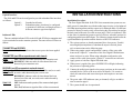
CAUTION! The transmitting element in some versions of the Pure Digital Fiberlink transmitter unit
is a solid-state Laser Diode located in the optical connector on the unit. This device emits invisible
infrared electromagnetic radiation which can be harmful to human eyes. The radiation from this
optical connector, if viewed at close range without a fiber optic cable connected to the optical
connector, may be of sufficient intensity to cause instantaneous damage to the retina of the eye.
Direct viewing of this radiation should be avoided at all times.
4
OPERATING POINTERS AND
TROUBLESHOOTING
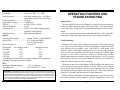
The 4160 and 4320 Series are available in versions that operate with most
multimode (MM) and single-mode (SM) optical fibers. Be certain that the
correct size fiber is being used for the particular transmitter/receiver combination.
Also be certain that the attenuation and bandwidth of the fiber optic cable
being used is within the range of the system’s loss budget specifications.
Multimode fiber optic cable contains an optical fiber with a light carrying
“core” that is only .0025 inches (62.5 microns) in diameter. Single-mode fiber
optic cable has an even smaller “core”, only 00032 to .0004 inches (8-10
microns). This is smaller than a human hair! As a result, any minute particles
of dirt or dust can easily block the fiber from accepting or radiating light.
Therefore, the key word is cleanliness. Always use the dust caps provided
with all optical connectors whenever they are exposed to air. Also, it is a good
idea to gently clean the tip of an optical connector with a lint-free cloth moistened with alcohol whenever dust is suspected.
The status of any of the audio indicator LEDs should provide the first clue
as to the origin of any operation failure. If all the LEDs are off, it usually
means that the fiber is broken or has too much attenuation. Next, be certain
that the input and output signal connections are proper. Due to the number of
positions, it is possible that there may be wrong connections.
Finally, although multimode and single mode devices may look the same,
they will not operate properly together. Using the wrong device or fiber can
9