1
SAFETY PRECAUTIONS
(Read these precautions before using this product.)
Before using this product, please read this manual and the relevant manuals carefully and pay full attention
to safety to handle the product correctly.
In this manual, the safety precautions are classified into two levels: "
WARNING" and "
CAUTION".
WARNING
Indicates that incorrect handling may cause hazardous conditions,
resulting in death or severe injury.
CAUTION
Indicates that incorrect handling may cause hazardous conditions,
resulting in minor or moderate injury or property damage.
Under some circumstances, failure to observe the precautions given under "
CAUTION" may lead to
serious consequences.
Observe the precautions of both levels because they are important for personal and system safety.
Make sure that the end users read this manual and then keep the manual in a safe place for future
reference.
1
[Design Precautions]
WARNING
● For the operating status of each station after a communication failure, refer to manuals relevant to the
network. Incorrect output or malfunction due to a communication failure may result in an accident.
● To prevent the malfunction of the programmable controller system due to harmful e-mails, take
preventive measures (such as antivirus measures) so that the mail server for this module does not
receive harmful e-mails.
● To maintain the safety of the programmable controller system against unauthorized access from
external devices via the network, take appropriate measures. To maintain the safety against
unauthorized access via the Internet, take measures such as installing a firewall.
● When connecting a peripheral with the CPU module or connecting an external device, such as a
personal computer, with an intelligent function module to modify data of a running programmable
controller, configure an interlock circuit in the program to ensure that the entire system will always
operate safely. For other forms of control (such as program modification or operating status change)
of a running programmable controller, read the relevant manuals carefully and ensure that the
operation is safe before proceeding. Especially, when a remote programmable controller is controlled
by an external device, immediate action cannot be taken if a problem occurs in the programmable
controller due to a communication failure. To prevent this, configure an interlock circuit in the program,
and determine corrective actions to be taken between the external device and CPU module in case of
a communication failure.
● Do not write any data in the system area of the buffer memory in the intelligent function module. Also,
do not use any use prohibited signals as an output signal from the programmable controller CPU to
the intelligent function module. Doing so may cause malfunction of the programmable controller
system.
[Design Precautions]
CAUTION
● Do not bundle the control wires and the communication cables with the main circuit and the power
wires, and do not install them close to each other. They should be installed at least 100 mm (3.94 in.)
away from each other. Failure to do so may generate noise that may cause malfunctions.
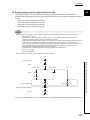
● When changing the operating status of the CPU module (such as remote RUN/STOP) from the
external device, select "Always wait for OPEN (Communication possible at STOP time)" for the "Initial
timing" setting in the network parameter. The communication line will be closed when "Do not wait for
OPEN (Communications impossible at STOP time)" is selected and the remote STOP is executed
from the external device. Consequently, the CPU module cannot reopen the communication line, and
the external device cannot execute the remote RUN.
2
[Installation Precautions]
CAUTION
● Use the programmable controller in an environment that meets the general specifications in the user's
manual for the CPU module used. Using the programmable controller in any other operating
environments may cause electric shocks, fires or malfunctions, or may damage or degrade the
module.
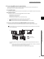
● While pressing the installation lever located at the bottom of module, insert the module fixing tab into
the fixing hole in the base unit until it stops. Then, securely mount the module with the fixing hole as a
supporting point. If the module is not installed properly, it may cause the module to malfunction, fail or
fall off. Secure the module with screws especially when it is used in an environment where constant
vibrations may occur.
● Be sure to tighten the screws using the specified torque. If the screws loose, it may cause the module
to short-circuit, malfunction or fall off. If the screws are tightened excessively, it may damage the
screws and cause the module to short-circuit, malfunction or fall off.
● Shut off the external power supply (all phases) used in the system before mounting or removing the
module. Failure to do so may cause product damage.
● Do not directly touch any conductive part or electronic component of the module. This may cause the
module to malfunction or fail.
[Wiring Instructions]
CAUTION
● Connectors for external devices and coaxial cables must be crimped or pressed with the tool specified
by the manufacturer, or must be correctly soldered. Incomplete connections may cause short circuit,
fire, or malfunction.
● Shut off the external power supply (all phases) used in the system before connecting the AUI cable.
● Securely connect the connector to the module. Poor contact may cause malfunction.
● Place the cables in a duct or clamp them. If not, dangling cable may swing or inadvertently be pulled,
resulting in damage to the module or cables or malfunction due to poor contact.
● Tighten the terminal screws using the specified torque. If the terminal screws are loose, it may cause
the module to short-circuit, malfunction or fall off. If the terminal screws are tightened excessively, it
may damage the screws and cause the module to short-circuit, malfunction or fall off.
● When disconnecting the cable from the module, do not pull the cable by the cable part. For the cable
with connector, hold the connector part of the cable. For the cable connected to the terminal block,
loosen the terminal screw. Pulling the cable connected to the module may result in malfunction or
damage to the module or cable.
● Be careful not to let any foreign matter such as wire chips get inside the module. They may cause fire,
as well as breakdowns and malfunctions of the module.
● A protective film is attached to the top of the module to prevent foreign matter, such as wire chips,
from entering the module during wiring. A protective film is attached to the top of the module to
prevent foreign matter, such as wire chips, from entering the module during wiring. Remove it for heat
dissipation before system operation.
3
[Setup and Maintenance Precautions]
WARNING
● Do not touch any terminal while power is on. Doing so will cause electric shock or malfunction.
● Shut off the external power supply (all phases) used in the system before cleaning the module or
retightening the terminal screws, connector screws, or module fixing screws. Failure to do so may
result in electric shock or cause the module to fail or malfunction.
[Setup and Maintenance Precautions]
CAUTION
● Do not disassemble or modify the modules. Doing so may cause failure, malfunction, injury, or a fire.
● Shut off the external power supply (all phases) used in the system before mounting or removing the
module.
● After the first use of the product, do not mount/remove the module to/from the base unit more than 50
times (IEC 61131-2 compliant). Exceeding the limit of 50 times may cause malfunction.
● Always make sure to touch the grounded metal to discharge the electricity charged in the body, etc.,
before touching the module. Failure to do so may cause a failure or malfunctions of the module.
[Precautions When Disposing of This Product]
CAUTION
● Dispose of this product as an industrial waste.
4
CONDITIONS OF USE FOR THE PRODUCT
(1) Mitsubishi programmable controller ("the PRODUCT") shall be used in conditions;
i) where any problem, fault or failure occurring in the PRODUCT, if any, shall not lead to any major
or serious accident; and
ii) where the backup and fail-safe function are systematically or automatically provided outside of
the PRODUCT for the case of any problem, fault or failure occurring in the PRODUCT.
(2) The PRODUCT has been designed and manufactured for the purpose of being used in general
industries.
MITSUBISHI SHALL HAVE NO RESPONSIBILITY OR LIABILITY (INCLUDING, BUT NOT
LIMITED TO ANY AND ALL RESPONSIBILITY OR LIABILITY BASED ON CONTRACT,
WARRANTY, TORT, PRODUCT LIABILITY) FOR ANY INJURY OR DEATH TO PERSONS OR
LOSS OR DAMAGE TO PROPERTY CAUSED BY the PRODUCT THAT ARE OPERATED OR
USED IN APPLICATION NOT INTENDED OR EXCLUDED BY INSTRUCTIONS, PRECAUTIONS,
OR WARNING CONTAINED IN MITSUBISHI'S USER, INSTRUCTION AND/OR SAFETY
MANUALS, TECHNICAL BULLETINS AND GUIDELINES FOR the PRODUCT.
("Prohibited Application")
Prohibited Applications include, but not limited to, the use of the PRODUCT in;
• Nuclear Power Plants and any other power plants operated by Power companies, and/or any
other cases in which the public could be affected if any problem or fault occurs in the PRODUCT.
• Railway companies or Public service purposes, and/or any other cases in which establishment of
a special quality assurance system is required by the Purchaser or End User.
• Aircraft or Aerospace, Medical applications, Train equipment, transport equipment such as
Elevator and Escalator, Incineration and Fuel devices, Vehicles, Manned transportation,
Equipment for Recreation and Amusement, and Safety devices, handling of Nuclear or
Hazardous Materials or Chemicals, Mining and Drilling, and/or other applications where there is a
significant risk of injury to the public or property.
Notwithstanding the above, restrictions Mitsubishi may in its sole discretion, authorize use of the
PRODUCT in one or more of the Prohibited Applications, provided that the usage of the PRODUCT
is limited only for the specific applications agreed to by Mitsubishi and provided further that no
special quality assurance or fail-safe, redundant or other safety features which exceed the general
specifications of the PRODUCTs are required. For details, please contact the Mitsubishi
representative in your region.
5
INTRODUCTION
Thank you for purchasing the Mitsubishi MELSEC-Q series programmable controllers. This manual describes the
operating procedure, system configuration, parameter settings, functions, programming, and troubleshooting of the
Ethernet interface modules: QJ71E71-100, QJ71E71-B5, and QJ71E71-B2 (hereafter referred to as E71).
Before using this product, please read this manual and the relevant manuals carefully and develop familiarity with the
functions and performance of the MELSEC-Q series programmable controller to handle the product correctly.
When applying the program examples introduced in this manual to the actual system, ensure the applicability and
confirm that it will not cause system control problems.
Please make sure that the end users read this manual.
COMPLIANCE WITH THE EMC AND LOW VOLTAGE
DIRECTIVES
(1) For programmable controller system
To ensure that Mitsubishi programmable controllers maintain EMC and Low Voltage Directives when incorporated
into other machinery or equipment, certain measures may be necessary. Please refer to one of the following
manuals.
• QCPU User's Manual (Hardware Design, Maintenance and Inspection)
• Safety Guidelines (This manual is included with the CPU module or base unit.)
The CE mark on the side of the programmable controller indicates compliance with EMC and Low Voltage
Directives.
(2) For the product
To ensure that this product maintains EMC and Low Voltage Directives, please refer to one of the manuals listed
under (1).
6
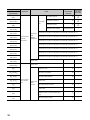
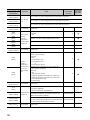
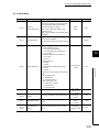
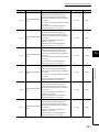
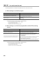
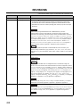
RELEVANT MANUALS
This manual describes the basic specifications, functions, and usage of the E71.
(1) E71 relevant manual
Manual name
Description
<manual number, model code>
MELSEC-Q/L Ethernet Interface Module User's
E-mail function, communication function (communications via CC-Link IE
Manual (Application)
Controller Network, CC-Link IE Field Network, MELSECNET/H, or
MELSECNET/10, and communications by using the data link instructions), and file
<SH-080010, 13JL89>
transfer (FTP server) function of the E71
MELSEC-Q/L Ethernet Interface Module User's
Manual (Web function)
Web function of the E71
<SH-080180, 13JR40>
MELSEC-Q/L MELSEC Communication Protocol
Reference Manual
<SH-080008, 13JF89>
Details of MELSEC communication protocol (MC protocol) that is used for data
communication between a target device and a CPU module
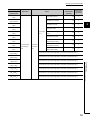
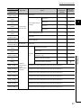
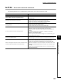
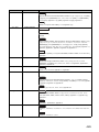
(2) Operating manual
Manual name
Description
<manual number, model code>
GX Works2 Version1 Operating Manual (Common)
<SH-080779, 13JU63>
GX Works2 Version 1 Operating Manual (Intelligent
Function Module)
<SH-080921, 13JU69>
GX Developer Version 8 Operating Manual
<SH-080373, 13JU41>
System configuration, parameter settings, and online operations (common to
Simple project and Structured project) of GX Works2
Parameter settings for intelligent function modules, monitoring operations, and the
predefined protocol support function of GX Works2
Operating methods of GX Developer, such as programming, printing, monitoring,
and debugging
7
CONTENTS
CONTENTS
SAFETY PRECAUTIONS . . . . . . . . . . . . . . . . . . . . . . . . . . . . . . . . . . . . . . . . . . . . . . . . . . . . . . . . . . . . . 1
CONDITIONS OF USE FOR THE PRODUCT . . . . . . . . . . . . . . . . . . . . . . . . . . . . . . . . . . . . . . . . . . . . . 5
INTRODUCTION . . . . . . . . . . . . . . . . . . . . . . . . . . . . . . . . . . . . . . . . . . . . . . . . . . . . . . . . . . . . . . . . . . . . 6
COMPLIANCE WITH THE EMC AND LOW VOLTAGE DIRECTIVES . . . . . . . . . . . . . . . . . . . . . . . . . . . 6
RELEVANT MANUALS . . . . . . . . . . . . . . . . . . . . . . . . . . . . . . . . . . . . . . . . . . . . . . . . . . . . . . . . . . . . . . . 7
MANUAL PAGE ORGANIZATION . . . . . . . . . . . . . . . . . . . . . . . . . . . . . . . . . . . . . . . . . . . . . . . . . . . . . . 14
TERM. . . . . . . . . . . . . . . . . . . . . . . . . . . . . . . . . . . . . . . . . . . . . . . . . . . . . . . . . . . . . . . . . . . . . . . . . . . . 15
PACKING LIST . . . . . . . . . . . . . . . . . . . . . . . . . . . . . . . . . . . . . . . . . . . . . . . . . . . . . . . . . . . . . . . . . . . . 17
CHAPTER 1 FEATURES
19
CHAPTER 2 PART NAMES
25
CHAPTER 3 SPECIFICATIONS
27
3.1
General Specifications . . . . . . . . . . . . . . . . . . . . . . . . . . . . . . . . . . . . . . . . . . . . . . . . . . . . . . . 27
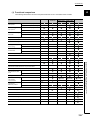
3.2
Performance Specifications . . . . . . . . . . . . . . . . . . . . . . . . . . . . . . . . . . . . . . . . . . . . . . . . . . . 27
3.3
Function List . . . . . . . . . . . . . . . . . . . . . . . . . . . . . . . . . . . . . . . . . . . . . . . . . . . . . . . . . . . . . . . 29
3.3.1
Function list . . . . . . . . . . . . . . . . . . . . . . . . . . . . . . . . . . . . . . . . . . . . . . . . . . . . . . . . . . . . . . 29
3.3.2
Use with other functions. . . . . . . . . . . . . . . . . . . . . . . . . . . . . . . . . . . . . . . . . . . . . . . . . . . . . 31
3.4
List of I/O Signals . . . . . . . . . . . . . . . . . . . . . . . . . . . . . . . . . . . . . . . . . . . . . . . . . . . . . . . . . . . 32
3.5
Buffer Memory . . . . . . . . . . . . . . . . . . . . . . . . . . . . . . . . . . . . . . . . . . . . . . . . . . . . . . . . . . . . . 34
3.5.1
Configuration of the buffer memory . . . . . . . . . . . . . . . . . . . . . . . . . . . . . . . . . . . . . . . . . . . . 34
3.5.2
List of buffer memory addresses . . . . . . . . . . . . . . . . . . . . . . . . . . . . . . . . . . . . . . . . . . . . . . 35
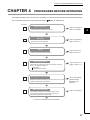
CHAPTER 4 PROCEDURES BEFORE OPERATION
57
CHAPTER 5 SYSTEM CONFIGURATION
59
5.1
5.2
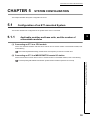
Configuration of an E71-mounted System . . . . . . . . . . . . . . . . . . . . . . . . . . . . . . . . . . . . . . . . 59
5.1.1
Applicable modules and base units, and the number of connectable modules . . . . . . . . . . . 59
5.1.2
For use with a Basic model QCPU or safety CPU . . . . . . . . . . . . . . . . . . . . . . . . . . . . . . . . . 60
5.1.3
For use in a multiple CPU system . . . . . . . . . . . . . . . . . . . . . . . . . . . . . . . . . . . . . . . . . . . . . 61
5.1.4
For use in a redundant system. . . . . . . . . . . . . . . . . . . . . . . . . . . . . . . . . . . . . . . . . . . . . . . . 62
5.1.5
For use in a MELSECNET/H remote I/O station . . . . . . . . . . . . . . . . . . . . . . . . . . . . . . . . . . 65
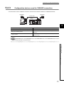
Network Components . . . . . . . . . . . . . . . . . . . . . . . . . . . . . . . . . . . . . . . . . . . . . . . . . . . . . . . . 68
5.2.1
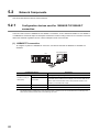
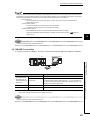
Configuration devices used for 100BASE-TX/10BASE-T connection . . . . . . . . . . . . . . . . . . 68
5.2.2
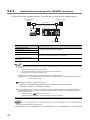
Configuration devices used for 10BASE5 connection . . . . . . . . . . . . . . . . . . . . . . . . . . . . . . 70
5.2.3
Configuration devices used for 10BASE2 connection . . . . . . . . . . . . . . . . . . . . . . . . . . . . . . 71
CHAPTER 6 INSTALLATION AND WIRING
6.1
6.2
8
72
Installation. . . . . . . . . . . . . . . . . . . . . . . . . . . . . . . . . . . . . . . . . . . . . . . . . . . . . . . . . . . . . . . . . 72
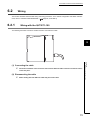
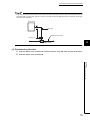
Wiring . . . . . . . . . . . . . . . . . . . . . . . . . . . . . . . . . . . . . . . . . . . . . . . . . . . . . . . . . . . . . . . . . . . . 73
6.2.1
Wiring with the QJ71E71-100 . . . . . . . . . . . . . . . . . . . . . . . . . . . . . . . . . . . . . . . . . . . . . . . . 73
6.2.2
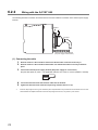
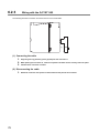
Wiring with the QJ71E71-B5 . . . . . . . . . . . . . . . . . . . . . . . . . . . . . . . . . . . . . . . . . . . . . . . . . 74
6.2.3
Wiring with the QJ71E71-B2 . . . . . . . . . . . . . . . . . . . . . . . . . . . . . . . . . . . . . . . . . . . . . . . . . 76
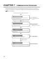
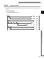
CHAPTER 7 COMMUNICATION PROCEDURE
7.1
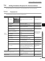
Setting Parameters Required for Communications . . . . . . . . . . . . . . . . . . . . . . . . . . . . . . . . . 79
7.1.1
7.2
Parameter list . . . . . . . . . . . . . . . . . . . . . . . . . . . . . . . . . . . . . . . . . . . . . . . . . . . . . . . . . . . . . 79
7.1.2
Basic setting. . . . . . . . . . . . . . . . . . . . . . . . . . . . . . . . . . . . . . . . . . . . . . . . . . . . . . . . . . . . . . 80
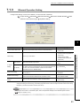
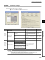
7.1.3
Ethernet Operation Setting. . . . . . . . . . . . . . . . . . . . . . . . . . . . . . . . . . . . . . . . . . . . . . . . . . . 81
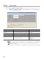
7.1.4
Open Setting . . . . . . . . . . . . . . . . . . . . . . . . . . . . . . . . . . . . . . . . . . . . . . . . . . . . . . . . . . . . . 83
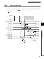
TCP/IP Communications . . . . . . . . . . . . . . . . . . . . . . . . . . . . . . . . . . . . . . . . . . . . . . . . . . . . . 85
7.2.1
7.3
78
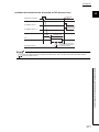
Establishing a connection . . . . . . . . . . . . . . . . . . . . . . . . . . . . . . . . . . . . . . . . . . . . . . . . . . . 85
7.2.2
Communication process. . . . . . . . . . . . . . . . . . . . . . . . . . . . . . . . . . . . . . . . . . . . . . . . . . . . . 86
7.2.3
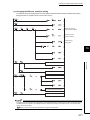
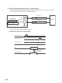
Active open procedure . . . . . . . . . . . . . . . . . . . . . . . . . . . . . . . . . . . . . . . . . . . . . . . . . . . . . . 87
7.2.4
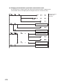
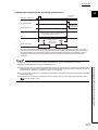
Passive open procedure . . . . . . . . . . . . . . . . . . . . . . . . . . . . . . . . . . . . . . . . . . . . . . . . . . . . 89
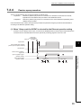
UDP/IP Communications . . . . . . . . . . . . . . . . . . . . . . . . . . . . . . . . . . . . . . . . . . . . . . . . . . . . . 93
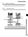
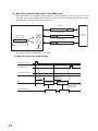
7.3.1
Communication process. . . . . . . . . . . . . . . . . . . . . . . . . . . . . . . . . . . . . . . . . . . . . . . . . . . . . 93
7.3.2
Open procedure . . . . . . . . . . . . . . . . . . . . . . . . . . . . . . . . . . . . . . . . . . . . . . . . . . . . . . . . . . . 94
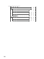
CHAPTER 8 CONNECTING MELSOFT PRODUCTS AND A GOT
96
8.1
Applications . . . . . . . . . . . . . . . . . . . . . . . . . . . . . . . . . . . . . . . . . . . . . . . . . . . . . . . . . . . . . . . 96
8.2
Data Communication Procedure. . . . . . . . . . . . . . . . . . . . . . . . . . . . . . . . . . . . . . . . . . . . . . . . 97
CHAPTER 9 MC PROTOCOL COMMUNICATIONS
99
9.1
Applications . . . . . . . . . . . . . . . . . . . . . . . . . . . . . . . . . . . . . . . . . . . . . . . . . . . . . . . . . . . . . . . 99
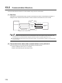
9.2
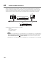
Communication Structure . . . . . . . . . . . . . . . . . . . . . . . . . . . . . . . . . . . . . . . . . . . . . . . . . . . . 100
9.3
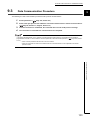
Data Communication Procedure. . . . . . . . . . . . . . . . . . . . . . . . . . . . . . . . . . . . . . . . . . . . . . . 101
9.4
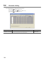
Parameter Setting. . . . . . . . . . . . . . . . . . . . . . . . . . . . . . . . . . . . . . . . . . . . . . . . . . . . . . . . . . 102
CHAPTER 10 SLMP COMMUNICATIONS
103
10.1
Applications . . . . . . . . . . . . . . . . . . . . . . . . . . . . . . . . . . . . . . . . . . . . . . . . . . . . . . . . . . . . . . 103
10.2
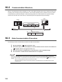
Communication Structure . . . . . . . . . . . . . . . . . . . . . . . . . . . . . . . . . . . . . . . . . . . . . . . . . . . . 104
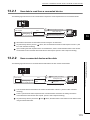
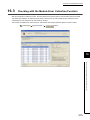
10.3
Data Communication Procedure. . . . . . . . . . . . . . . . . . . . . . . . . . . . . . . . . . . . . . . . . . . . . . . 104
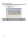
10.4
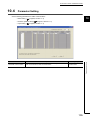
Parameter Setting. . . . . . . . . . . . . . . . . . . . . . . . . . . . . . . . . . . . . . . . . . . . . . . . . . . . . . . . . . 105
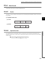
10.5
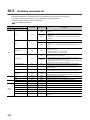
Available command list . . . . . . . . . . . . . . . . . . . . . . . . . . . . . . . . . . . . . . . . . . . . . . . . . . . . . . 106
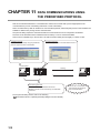
CHAPTER 11 DATA COMMUNICATIONS USING THE PREDEFINED PROTOCOL
108
11.1
Data Communication Procedure. . . . . . . . . . . . . . . . . . . . . . . . . . . . . . . . . . . . . . . . . . . . . . . 110
11.2
Communication Type of Protocols . . . . . . . . . . . . . . . . . . . . . . . . . . . . . . . . . . . . . . . . . . . . . 113
11.3
Packet Elements. . . . . . . . . . . . . . . . . . . . . . . . . . . . . . . . . . . . . . . . . . . . . . . . . . . . . . . . . . . 114
11.4
Execution Condition of Predefined Protocol Communication . . . . . . . . . . . . . . . . . . . . . . . . . 121
11.5
Example of Predefined Protocol Communications . . . . . . . . . . . . . . . . . . . . . . . . . . . . . . . . . 124
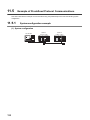
11.5.1
System configuration example . . . . . . . . . . . . . . . . . . . . . . . . . . . . . . . . . . . . . . . . . . . . . . . 124
11.5.2
Parameter Setting . . . . . . . . . . . . . . . . . . . . . . . . . . . . . . . . . . . . . . . . . . . . . . . . . . . . . . . . 125
11.5.3
Program example. . . . . . . . . . . . . . . . . . . . . . . . . . . . . . . . . . . . . . . . . . . . . . . . . . . . . . . . . 131
9
CHAPTER 12 COMMUNICATIONS USING A FIXED BUFFER
12.1
135
Applications . . . . . . . . . . . . . . . . . . . . . . . . . . . . . . . . . . . . . . . . . . . . . . . . . . . . . . . . . . . . . . 135
12.1.1 Differences between the "Procedure Exist" and "No Procedure" control methods . . . . . . . 135
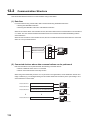
12.2
Communication Structure . . . . . . . . . . . . . . . . . . . . . . . . . . . . . . . . . . . . . . . . . . . . . . . . . . . . 136
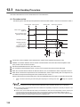
12.3
Data Sending Procedure . . . . . . . . . . . . . . . . . . . . . . . . . . . . . . . . . . . . . . . . . . . . . . . . . . . . 138
12.4
Data Receiving Procedure . . . . . . . . . . . . . . . . . . . . . . . . . . . . . . . . . . . . . . . . . . . . . . . . . . . 140
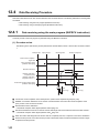
12.4.1 Data receiving using the main program (BUFRCV instruction) . . . . . . . . . . . . . . . . . . . . . . 140
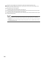
12.4.2 Data receiving using an interrupt program (BUFRCVS instruction) . . . . . . . . . . . . . . . . . . . 143
12.5
Parameter Setting. . . . . . . . . . . . . . . . . . . . . . . . . . . . . . . . . . . . . . . . . . . . . . . . . . . . . . . . . . 145
12.5.1 Parameter setting when using an interrupt program . . . . . . . . . . . . . . . . . . . . . . . . . . . . . . 146
12.6
Data Format . . . . . . . . . . . . . . . . . . . . . . . . . . . . . . . . . . . . . . . . . . . . . . . . . . . . . . . . . . . . . . 148
12.6.1 Header . . . . . . . . . . . . . . . . . . . . . . . . . . . . . . . . . . . . . . . . . . . . . . . . . . . . . . . . . . . . . . . . . 148
12.6.2 Application data . . . . . . . . . . . . . . . . . . . . . . . . . . . . . . . . . . . . . . . . . . . . . . . . . . . . . . . . . . 148
12.7
Pairing Open. . . . . . . . . . . . . . . . . . . . . . . . . . . . . . . . . . . . . . . . . . . . . . . . . . . . . . . . . . . . . . 155
12.7.1 Applications . . . . . . . . . . . . . . . . . . . . . . . . . . . . . . . . . . . . . . . . . . . . . . . . . . . . . . . . . . . . . 155
12.7.2 Parameter setting. . . . . . . . . . . . . . . . . . . . . . . . . . . . . . . . . . . . . . . . . . . . . . . . . . . . . . . . . 156
12.8
Broadcast Communications . . . . . . . . . . . . . . . . . . . . . . . . . . . . . . . . . . . . . . . . . . . . . . . . . . 157
12.8.1 Sending/receiving procedures . . . . . . . . . . . . . . . . . . . . . . . . . . . . . . . . . . . . . . . . . . . . . . . 157
12.8.2 Parameter setting. . . . . . . . . . . . . . . . . . . . . . . . . . . . . . . . . . . . . . . . . . . . . . . . . . . . . . . . . 159
12.8.3 Precautions . . . . . . . . . . . . . . . . . . . . . . . . . . . . . . . . . . . . . . . . . . . . . . . . . . . . . . . . . . . . . 161
12.9
Example of Communications Using a Fixed Buffer . . . . . . . . . . . . . . . . . . . . . . . . . . . . . . . . 162
12.9.1 System configuration . . . . . . . . . . . . . . . . . . . . . . . . . . . . . . . . . . . . . . . . . . . . . . . . . . . . . . 162
12.9.2 Parameter setting. . . . . . . . . . . . . . . . . . . . . . . . . . . . . . . . . . . . . . . . . . . . . . . . . . . . . . . . . 162
12.9.3 Program . . . . . . . . . . . . . . . . . . . . . . . . . . . . . . . . . . . . . . . . . . . . . . . . . . . . . . . . . . . . . . . . 166
CHAPTER 13 COMMUNICATIONS USING A RANDOM ACCESS BUFFER
13.1
13.2
171
Applications . . . . . . . . . . . . . . . . . . . . . . . . . . . . . . . . . . . . . . . . . . . . . . . . . . . . . . . . . . . . . . 171
Communication Structure . . . . . . . . . . . . . . . . . . . . . . . . . . . . . . . . . . . . . . . . . . . . . . . . . . . . 172
13.2.1 How data is read from a connected device . . . . . . . . . . . . . . . . . . . . . . . . . . . . . . . . . . . . . 173
13.2.2 How a connected device writes data . . . . . . . . . . . . . . . . . . . . . . . . . . . . . . . . . . . . . . . . . . 173
13.3
Parameter Setting. . . . . . . . . . . . . . . . . . . . . . . . . . . . . . . . . . . . . . . . . . . . . . . . . . . . . . . . . . 174
13.4
Data Format . . . . . . . . . . . . . . . . . . . . . . . . . . . . . . . . . . . . . . . . . . . . . . . . . . . . . . . . . . . . . . 175
13.4.1 Header . . . . . . . . . . . . . . . . . . . . . . . . . . . . . . . . . . . . . . . . . . . . . . . . . . . . . . . . . . . . . . . . . 175
13.4.2 Application data . . . . . . . . . . . . . . . . . . . . . . . . . . . . . . . . . . . . . . . . . . . . . . . . . . . . . . . . . . 175
13.4.3 Examples of command and response formats. . . . . . . . . . . . . . . . . . . . . . . . . . . . . . . . . . . 180
10
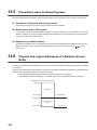
13.5
Precautions when Creating Programs . . . . . . . . . . . . . . . . . . . . . . . . . . . . . . . . . . . . . . . . . .184
13.6
Physical and Logical Addresses of a Random Access Buffer . . . . . . . . . . . . . . . . . . . . . . . . 184
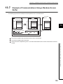
13.7
Example of Communications Using a Random Access Buffer . . . . . . . . . . . . . . . . . . . . . . . . 185
CHAPTER 14 OTHER FUNCTIONS
14.1
186
Router Relay Function . . . . . . . . . . . . . . . . . . . . . . . . . . . . . . . . . . . . . . . . . . . . . . . . . . . . . . 186
14.1.1 Applications . . . . . . . . . . . . . . . . . . . . . . . . . . . . . . . . . . . . . . . . . . . . . . . . . . . . . . . . . . . . . 186
14.1.2 Parameter settings . . . . . . . . . . . . . . . . . . . . . . . . . . . . . . . . . . . . . . . . . . . . . . . . . . . . . . . . 186
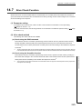
14.2
Communications Using an Auto-open UDP Port . . . . . . . . . . . . . . . . . . . . . . . . . . . . . . . . . . 191
14.2.1 Application . . . . . . . . . . . . . . . . . . . . . . . . . . . . . . . . . . . . . . . . . . . . . . . . . . . . . . . . . . . . . . 191
14.3
Remote Password . . . . . . . . . . . . . . . . . . . . . . . . . . . . . . . . . . . . . . . . . . . . . . . . . . . . . . . . . 192
14.3.1 Application . . . . . . . . . . . . . . . . . . . . . . . . . . . . . . . . . . . . . . . . . . . . . . . . . . . . . . . . . . . . . . 192
14.3.2 Remote password setting processes (unlock and lock processes) . . . . . . . . . . . . . . . . . . . 193
14.3.3 Remote password check procedure. . . . . . . . . . . . . . . . . . . . . . . . . . . . . . . . . . . . . . . . . . . 194
14.3.4 Comparison of functions according to the remote password check status
(enabled/disabled) . . . . . . . . . . . . . . . . . . . . . . . . . . . . . . . . . . . . . . . . . . . . . . . 197
14.3.5 Precautions . . . . . . . . . . . . . . . . . . . . . . . . . . . . . . . . . . . . . . . . . . . . . . . . . . . . . . . . . . . . . 199
14.3.6 Parameter settings . . . . . . . . . . . . . . . . . . . . . . . . . . . . . . . . . . . . . . . . . . . . . . . . . . . . . . . . 201
14.4
Hub Connection Status Monitor Function . . . . . . . . . . . . . . . . . . . . . . . . . . . . . . . . . . . . . . . . 202
14.5
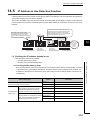
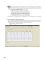
IP Address in Use Detection Function . . . . . . . . . . . . . . . . . . . . . . . . . . . . . . . . . . . . . . . . . . 203
14.6
Redundant System Function . . . . . . . . . . . . . . . . . . . . . . . . . . . . . . . . . . . . . . . . . . . . . . . . . 205
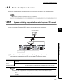
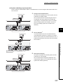
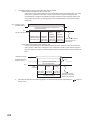
14.6.1 System switching request to the control system CPU module. . . . . . . . . . . . . . . . . . . . . . . 205
14.6.2 Communication path bypass function . . . . . . . . . . . . . . . . . . . . . . . . . . . . . . . . . . . . . . . . . 211
14.6.3 Parameter settings . . . . . . . . . . . . . . . . . . . . . . . . . . . . . . . . . . . . . . . . . . . . . . . . . . . . . . . . 212
14.6.4 Data communications in a redundant system . . . . . . . . . . . . . . . . . . . . . . . . . . . . . . . . . . . 215
14.7
Alive Check Function . . . . . . . . . . . . . . . . . . . . . . . . . . . . . . . . . . . . . . . . . . . . . . . . . . . . . . . 225
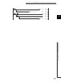
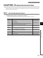
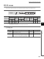
CHAPTER 15 DEDICATED INSTRUCTIONS
15.1
15.2
227
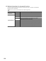
List of Dedicated Instructions . . . . . . . . . . . . . . . . . . . . . . . . . . . . . . . . . . . . . . . . . . . . . . . . . 227
Parameter Settings for Using Dedicated Instructions . . . . . . . . . . . . . . . . . . . . . . . . . . . . . . . 229
15.2.1 When using data link instructions. . . . . . . . . . . . . . . . . . . . . . . . . . . . . . . . . . . . . . . . . . . . . 229
15.3
Precautions for Dedicated Instructions . . . . . . . . . . . . . . . . . . . . . . . . . . . . . . . . . . . . . . . . . . 229
15.4
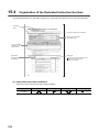
Organization of the Dedicated Instruction Sections . . . . . . . . . . . . . . . . . . . . . . . . . . . . . . . . 230
15.5
ZP.OPEN . . . . . . . . . . . . . . . . . . . . . . . . . . . . . . . . . . . . . . . . . . . . . . . . . . . . . . . . . . . . . . . . 232
15.6
ZP.CLOSE . . . . . . . . . . . . . . . . . . . . . . . . . . . . . . . . . . . . . . . . . . . . . . . . . . . . . . . . . . . . . . . 236
15.7
GP.ECPRTCL . . . . . . . . . . . . . . . . . . . . . . . . . . . . . . . . . . . . . . . . . . . . . . . . . . . . . . . . . . . . . 239
15.8
ZP.BUFSND . . . . . . . . . . . . . . . . . . . . . . . . . . . . . . . . . . . . . . . . . . . . . . . . . . . . . . . . . . . . . . 249
15.9
ZP.BUFRCV . . . . . . . . . . . . . . . . . . . . . . . . . . . . . . . . . . . . . . . . . . . . . . . . . . . . . . . . . . . . . . 253
15.10 Z.BUFRCVS . . . . . . . . . . . . . . . . . . . . . . . . . . . . . . . . . . . . . . . . . . . . . . . . . . . . . . . . . . . . . . 257
15.11 ZP.ERRCLR . . . . . . . . . . . . . . . . . . . . . . . . . . . . . . . . . . . . . . . . . . . . . . . . . . . . . . . . . . . . . . 260
15.12 ZP.ERRRD. . . . . . . . . . . . . . . . . . . . . . . . . . . . . . . . . . . . . . . . . . . . . . . . . . . . . . . . . . . . . . . 263
15.13 ZP.UINI . . . . . . . . . . . . . . . . . . . . . . . . . . . . . . . . . . . . . . . . . . . . . . . . . . . . . . . . . . . . . . . . . 267
11
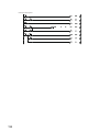
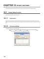
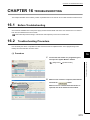
CHAPTER 16 TROUBLESHOOTING
273
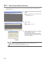
16.1
Before Troubleshooting . . . . . . . . . . . . . . . . . . . . . . . . . . . . . . . . . . . . . . . . . . . . . . . . . . . . . 273
16.2
Troubleshooting Procedure . . . . . . . . . . . . . . . . . . . . . . . . . . . . . . . . . . . . . . . . . . . . . . . . . . 273
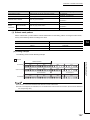
16.3
Checking with the Module Error Collection Function . . . . . . . . . . . . . . . . . . . . . . . . . . . . . . . 275
16.4
Checking the LEDs . . . . . . . . . . . . . . . . . . . . . . . . . . . . . . . . . . . . . . . . . . . . . . . . . . . . . . . . . 276
16.4.1 If the RUN LED turns off . . . . . . . . . . . . . . . . . . . . . . . . . . . . . . . . . . . . . . . . . . . . . . . . . . . 276
16.4.2 If the ERR. LED or COM.ERR. LED turns on . . . . . . . . . . . . . . . . . . . . . . . . . . . . . . . . . . . 276
16.4.3 If the SD LED does not flash when data is sent. . . . . . . . . . . . . . . . . . . . . . . . . . . . . . . . . . 277
16.4.4 If data cannot be received with the RD LED off . . . . . . . . . . . . . . . . . . . . . . . . . . . . . . . . . . 277
16.5
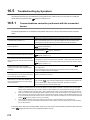
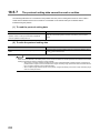
Troubleshooting by Symptom . . . . . . . . . . . . . . . . . . . . . . . . . . . . . . . . . . . . . . . . . . . . . . . . . 278
16.5.1 Communications cannot be performed with the connected device.. . . . . . . . . . . . . . . . . . . 278
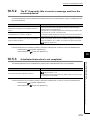
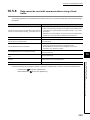
16.5.2 The E71 frequently fails to receive a message sent from the connected device. . . . . . . . . 279
16.5.3 A dedicated instruction is not completed.. . . . . . . . . . . . . . . . . . . . . . . . . . . . . . . . . . . . . . . 279
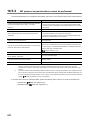
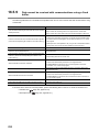
16.5.4 MC protocol communications cannot be performed. . . . . . . . . . . . . . . . . . . . . . . . . . . . . . . 280
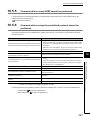
16.5.5 Communications using SLMP cannot be performed.. . . . . . . . . . . . . . . . . . . . . . . . . . . . . . 281
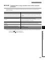
16.5.6 Communications using the predefined protocol cannot be performed. . . . . . . . . . . . . . . . . 281
16.5.7 The protocol setting data cannot be read or written. . . . . . . . . . . . . . . . . . . . . . . . . . . . . . . 282
16.5.8 Data cannot be sent with communications using a fixed buffer.. . . . . . . . . . . . . . . . . . . . . . 283
16.5.9 Data cannot be received with communications using a fixed buffer. . . . . . . . . . . . . . . . . . . 284
16.5.10 Communications using a random access buffer cannot be performed. . . . . . . . . . . . . . . . . 285
16.5.11 An e-mail cannot be sent. . . . . . . . . . . . . . . . . . . . . . . . . . . . . . . . . . . . . . . . . . . . . . . . . . . 286
16.5.12 An e-mail cannot be received. . . . . . . . . . . . . . . . . . . . . . . . . . . . . . . . . . . . . . . . . . . . . . . . 287
16.5.13 Communications using data link instructions cannot be performed. . . . . . . . . . . . . . . . . . . 288
16.5.14 Communications cannot be performed during OPS connection in a redundant system.. . . 288
16.5.15 Systems cannot be switched in a redundant system. . . . . . . . . . . . . . . . . . . . . . . . . . . . . . 289
16.6
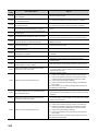
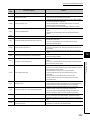
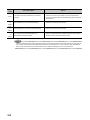
Error Code List . . . . . . . . . . . . . . . . . . . . . . . . . . . . . . . . . . . . . . . . . . . . . . . . . . . . . . . . . . . . 290
16.6.1 End codes returned to a connected device during data communications . . . . . . . . . . . . . . 300
16.6.2 Abnormal codes returned during communications using an A-compatible 1E frame. . . . . . 303
16.6.3 Error codes stored in the buffer memory . . . . . . . . . . . . . . . . . . . . . . . . . . . . . . . . . . . . . . . 304
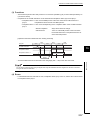
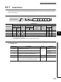
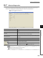
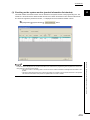
16.7
Ethernet Diagnostics. . . . . . . . . . . . . . . . . . . . . . . . . . . . . . . . . . . . . . . . . . . . . . . . . . . . . . . . 329
16.8
How to Turn Off the COM.ERR. LED . . . . . . . . . . . . . . . . . . . . . . . . . . . . . . . . . . . . . . . . . . . 330
APPENDICES
331
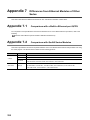
Appendix 1 Processing Time . . . . . . . . . . . . . . . . . . . . . . . . . . . . . . . . . . . . . . . . . . . . . . . . . . . . . . 331
Appendix 2 Port Numbers Used for the E71 . . . . . . . . . . . . . . . . . . . . . . . . . . . . . . . . . . . . . . . . . . 340
Appendix 3 New and Improved Functions . . . . . . . . . . . . . . . . . . . . . . . . . . . . . . . . . . . . . . . . . . . . 341
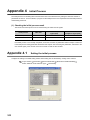
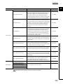
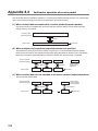
Appendix 4 Initial Process . . . . . . . . . . . . . . . . . . . . . . . . . . . . . . . . . . . . . . . . . . . . . . . . . . . . . . . . 344
Appendix 4.1
Setting the initial process . . . . . . . . . . . . . . . . . . . . . . . . . . . . . . . . . . . . . . 344
Appendix 4.2
Reinitialization process . . . . . . . . . . . . . . . . . . . . . . . . . . . . . . . . . . . . . . . 348
Appendix 5 Line Status Check . . . . . . . . . . . . . . . . . . . . . . . . . . . . . . . . . . . . . . . . . . . . . . . . . . . . . 354
Appendix 5.1
PING test . . . . . . . . . . . . . . . . . . . . . . . . . . . . . . . . . . . . . . . . . . . . . . . . 354
Appendix 5.2
Loopback test . . . . . . . . . . . . . . . . . . . . . . . . . . . . . . . . . . . . . . . . . . . . . 360
Appendix 6 Self-Diagnostic Tests. . . . . . . . . . . . . . . . . . . . . . . . . . . . . . . . . . . . . . . . . . . . . . . . . . . 364
12
Appendix 6.1
Self-loopback test . . . . . . . . . . . . . . . . . . . . . . . . . . . . . . . . . . . . . . . . . . 364
Appendix 6.2
Hardware test (H/W Test). . . . . . . . . . . . . . . . . . . . . . . . . . . . . . . . . . . . . . 365
Appendix 7 Differences from Ethernet Modules of Other Series . . . . . . . . . . . . . . . . . . . . . . . . . . . 366
Appendix 7.1
Comparison with a Built-in Ethernet port QCPU . . . . . . . . . . . . . . . . . . . . . . . 366
Appendix 7.2
Comparison with QnA/A Series Modules. . . . . . . . . . . . . . . . . . . . . . . . . . . . 366
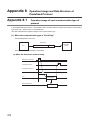
Appendix 8 Operation Image and Data Structure of Predefined Protocol . . . . . . . . . . . . . . . . . . . . 370
Appendix 8.1
Operation image of each communication type of protocol. . . . . . . . . . . . . . . . . 370
Appendix 8.2
Verification operation of receive packet. . . . . . . . . . . . . . . . . . . . . . . . . . . . . 376
Appendix 8.3
Data examples of packet elements . . . . . . . . . . . . . . . . . . . . . . . . . . . . . . . 377
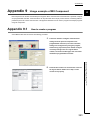
Appendix 9 Usage example of MX Component . . . . . . . . . . . . . . . . . . . . . . . . . . . . . . . . . . . . . . . . 381
Appendix 9.1
How to create a program . . . . . . . . . . . . . . . . . . . . . . . . . . . . . . . . . . . . . . 381
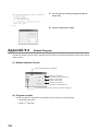
Appendix 9.2
Sample Program . . . . . . . . . . . . . . . . . . . . . . . . . . . . . . . . . . . . . . . . . . . 382
Appendix 10 Sample Program on the Connected Device Side . . . . . . . . . . . . . . . . . . . . . . . . . . . . . 387
Appendix 10.1 When Visual C++®.NET is used (single CPU system) . . . . . . . . . . . . . . . . . . . 389
Appendix 10.2 When Visual C++®.NET is used (redundant system) . . . . . . . . . . . . . . . . . . . . 398
Appendix 10.3 When Visual Basic®.NET is used . . . . . . . . . . . . . . . . . . . . . . . . . . . . . . . . 409
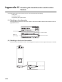
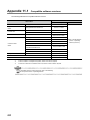
Appendix 11 Checking the Serial Number and Function Version . . . . . . . . . . . . . . . . . . . . . . . . . . . 418
Appendix 11.1 Compatible software versions . . . . . . . . . . . . . . . . . . . . . . . . . . . . . . . . . . . 420
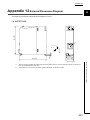
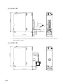
Appendix 12 External Dimension Diagram . . . . . . . . . . . . . . . . . . . . . . . . . . . . . . . . . . . . . . . . . . . . 421
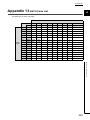
Appendix 13 ASCII Code List. . . . . . . . . . . . . . . . . . . . . . . . . . . . . . . . . . . . . . . . . . . . . . . . . . . . . . . 423
INDEX
425
REVISIONS . . . . . . . . . . . . . . . . . . . . . . . . . . . . . . . . . . . . . . . . . . . . . . . . . . . . . . . . . . . . . . . . . . . . . . 428
WARRANTY . . . . . . . . . . . . . . . . . . . . . . . . . . . . . . . . . . . . . . . . . . . . . . . . . . . . . . . . . . . . . . . . . . . . . 431
13
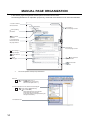
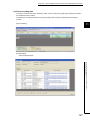
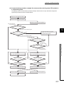
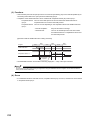
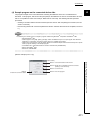
MANUAL PAGE ORGANIZATION
In this manual, pages are organized and the symbols are used as shown below.
The following illustration is for explanation purpose only, and should not be referred to as an actual documentation.
"" is used for window
names and items.
The chapter of
the current page is shown.
shows operating
procedures.
shows mouse
operations.*1
[ ] is used for items
in the menu bar and
the project window.
The section of
the current page is shown.
Ex. shows setting or
operating examples.
shows reference
manuals.
shows notes that
requires attention.
shows
reference pages.
shows useful
information.
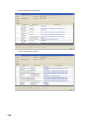
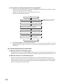
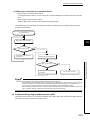
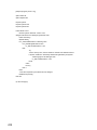
*1
The mouse operation example is provided below.
Menu bar
Ex.
[Online]
[Write to PLC...]
Select [Online] on the menu bar,
and then select [Write to PLC...].
A window selected in the view selection area is displayed.
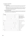
Ex.
[Parameter]
Project window
[PLC Parameter]
Select [Project] from the view selection
area to open the Project window.
In the Project window, expand [Parameter] and
select [PLC Parameter].
View selection area
14
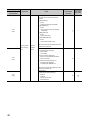
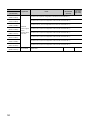
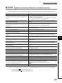
TERM
Unless otherwise specified, this manual uses the following terms.
Term
ACPU
AnACPU
AnNCPU
AnUCPU
ARP
Description
A generic term for the AnNCPU, AnACPU, and AnUCPU
A generic term for the A2ACPU, A2ACPU-S1, A2ACPUP21/R21, A2ACPUP21/R21-S1, A3ACPU,
and A3ACPUP21/R21
A generic term for the A1NCPU, A1NCPUP21/R21, A2NCPU, A2NCPU-S1, A2NCPUP21/R21,
A2NCPUP21/R21-S1, A3NCPU, and A3NCPUP21/R21
A generic term for the A2UCPU, A2UCPU-S1, A2ASCPU, A2ASCPU-S1, A3UCPU, and A4UCPU
The abbreviation for Address Resolution Protocol. This protocol is used to obtain the MAC address
of Ethernet from an IP address.
BUFRCV
The abbreviation for ZP.BUFRCV
BUFRCVS
The abbreviation for Z.BUFRCVS
BUFSND
The abbreviation for ZP.BUFSND
CLOSE
The abbreviation for ZP.CLOSE
C24
Another name for the Q series serial communication module
DNS
The abbreviation for Domain Name System. This system is mainly used to convert host names on
the Internet or domain names used for e-mails to IP addresses.
ECPRTCL
The abbreviation for GP.ECPRTCL
ERRCLR
The abbreviation for ZP.ERRCLR
ERRRD
The abbreviation for ZP.ERRRD
A generic term for the Q03UDVCPU, Q03UDECPU, Q04UDVCPU, Q04UDEHCPU,
Built-in Ethernet port QCPU
Q06UDVCPU, Q06UDEHCPU, Q10UDEHCPU, Q13UDVCPU, Q13UDEHCPU, Q20UDEHCPU,
Q26UDVCPU, Q26UDEHCPU, Q50UDEHCPU, and Q100UDEHCPU
E71
A generic term for the Ethernet interface modules: QJ71E71-100, QJ71E71-B5, and QJ71E71-B2
E71-mounted station
The abbreviation for the station where the E71 is mounted
FTP
GX Developer
GX Works2
HTTP
ICMP
IP
MAC address
The abbreviation for File Transfer Protocol. This protocol is used to transfer data files over a
network.
The product name of the software package for the MELSEC programmable controllers
The abbreviation for Hyper Text Transfer Protocol. This protocol is used to send and receive
content, such as HTML files, between a Web browser and a Web server.
The abbreviation for Internet Control Message Protocol. This protocol is used to exchange
messages of errors in an IP network or other information related to an Ethernet network.
The abbreviation for Internet Protocol
A unique identifier assigned to each external device on a network. This address is also known as
an Ethernet hardware address.
The abbreviation for MELSEC Communication Protocol. This protocol is used to access MC
MC protocol
protocol supporting modules, such as the C24 and E71, or programmable controllers connected to
MELSECNET/H
The abbreviation for a MELSECNET/H network system
MELSECNET/H remote I/O station
A generic term for the QJ72LP25-25, QJ72LP25G, and QJ72BR15
MELSECNET/10
The abbreviation for a MELSECNET/10 network system
MRECV
The abbreviation for ZP.MRECV
MSEND
The abbreviation for ZP.MSEND
MX Component
The abbreviation for MX Component (SW0D5C-ACT-E or later)
OPEN
The abbreviation for ZP.OPEN
MC protocol supporting modules from external devices.
15
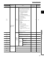
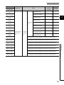
Term
OPS
POP3
QCPU
QCPU-mounted station
QnACPU
READ
Description
A generic term for the partner products with built-in EZSocket that supports a redundant system.
The E71 communicates with an OPS using a connection specified by a user.
The abbreviation for Post Office Protocol Ver.3. This protocol is used to transfer e-mails from a
mail server to a local computer.
A generic term for the Basic model QCPU, High Performance model QCPU, Process CPU,
Redundant CPU, and Universal model QCPU
The abbreviation for the programmable controller where the QCPU is mounted
A generic term for the Q2ACPU, Q2ACPU-S1, Q2ASCPU, Q2ASCPU-S1, Q2ASHCPU,
Q2ASHCPU-S1, Q3ACPU, Q4ACPU, and Q4ARCPU
The abbreviation for JP.READ and GP.READ
RECV
The abbreviation for JP.RECV and GP.RECV
RECVS
The abbreviation for Z.RECVS
REQ
The abbreviation for J.REQ, JP.REQ, G.REQ, and GP.REQ
SEND
The abbreviation for JP.SEND and GP.SEND
The abbreviation for Seamless Message Protocol.
SLMP
This protocol is used to access an SLMP-compatible device or a programmable controller
connected to an SLMP-compatible device from an external device.
SMTP
The abbreviation for Simple Mail Transfer Protocol. This protocol is used to transfer e-mails over the Internet.
SREAD
The abbreviation for JP.SREAD and GP.SREAD
SWRITE
The abbreviation for JP.SWRITE and GP.SWRITE
UINI
The abbreviation for ZP.UINI
WRITE
The abbreviation for JP.WRITE and GP.WRITE
ZNRD
The abbreviation for J.ZNRD and JP.ZNRD
ZNWR
The abbreviation for J.ZNWR and JP.ZNWR
Intelligent function module
A module that has functions other than an input or output, such as an A/D converter module and
D/A converter module
A number used to logically divide one network into multiple subnetworks and manage them easily.
The following Ethernet network systems can be configured:
Subnet mask
A small-scale Ethernet network system in which multiple network devices are connected
A medium- or large-scale network system in which multiple small-scale network systems are
connected via routers or other network communication devices
A function of GX Works2.
Predefined protocol support function
This function sets protocols appropriate to each external device and reads/writes protocol setting
data from/to the flash ROM of the E71.
Device
A device (X, Y, M, D, or others) in a CPU module
High Performance model QCPU
A generic term for the Q02(H)CPU, Q06HCPU, Q12HCPU, and Q25HCPU
Buffer memory
Buffer memory address
A memory in an intelligent function module, where data (such as setting values and monitoring
values) exchanged with a CPU module are stored
An address that indicates the storage location of data assigned to the buffer memory in an
intelligent function module
Programming tool
A generic term for GX Works2 and GX Developer
Process CPU
A generic term for the Q02PHCPU, Q06PHCPU, Q12PHCPU, and Q25PHCPU
Basic model QCPU
A generic term for the Q00(J)CPU and Q01CPU
A generic term for the Q00UJCPU, Q00UCPU, Q01UCPU, Q02UCPU, Q03UDCPU,
Q03UDVCPU, Q03UDECPU, Q04UDHCPU, Q04UDVCPU, Q04UDEHCPU, Q06UDHCPU,
Universal model QCPU
Q06UDVCPU, Q06UDEHCPU, Q10UDHCPU, Q10UDEHCPU, Q13UDHCPU, Q13UDVCPU,
Q13UDEHCPU, Q20UDHCPU, Q20UDEHCPU, Q26UDHCPU, Q26UDVCPU, Q26UDEHCPU,
Q50UDEHCPU, and Q100UDEHCPU
Redundant CPU
A generic term for the Q12PRHCPU and Q25PRHCPUU
Safety CPU
Another name for the QS001CPU
Dedicated Instruction
An instruction that simplifies programming for using functions of intelligent function modules
16
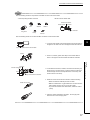
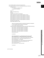
PACKING LIST
The following items are included in the package of this product. Before use, check that all the items are included.
QJ71E71-100
QJ71E71-100
Before Using the Product
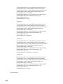
QJ71E71-B5
QJ71E71-B5
Before Using the Product
17
QJ71E71-B2
QJ71E71-B2
18
Before Using the Product
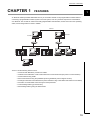
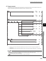
CHAPTER 1 FEATURES
CHAPTER 1
FEATURES
1
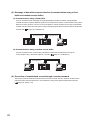
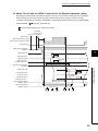
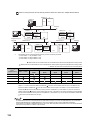
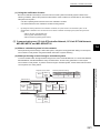
An Ethernet module (hereafter abbreviated as E71) is an interface module on the programmable controller side for
connecting a programmable controller system to the host system, such as a personal computer and a workstation,
over Ethernet. The module can collect and modify programmable controller data, monitor and control CPU operating
status, and exchange data in TCP/IP or UDP/IP.
Internet
Provider
Provider
Own station
Connected device
Another station
Connected device
Web server
Programming tool
The E71 has the following basic functions.
• Connection with MELSOFT products and a GOT
• Collection and modification of CPU module data from connected devices (MC protocol communications)
• Communications using SLMP
• Data communications using the predefined protocol (predefined protocol support function)
• Exchange of data with connected devices (communications using a fixed buffer and random access buffer)
• Prevention of unauthorized access through a remote password
• E-mail sending/receiving (e-mail function)
• Data sending/receiving using the Web function
19
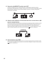
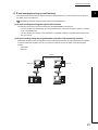
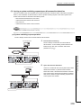
(1) Connection with MELSOFT products and a GOT
In Ethernet, a programming tool can create programming of a programmable controller and monitor a
programmable controller (MELSOFT connection), and the GOT can monitor and test a programmable controller.
Remote operations making full use of the Ethernet capability, long-distance connectivity and high-speed
communications, are achieved.
GOT
E71
Programming tool
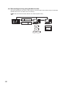
(2) Collection and modification of CPU module data from connected devices (MC
protocol communications)
The MC protocol enables connected devices to access MC protocol supporting modules over Ethernet. The E71
can communicate with a personal computer and HMI (Human Machine Interface) as long as the connected
devices can receive/send messages in the MC protocol control procedure. By using a separately sold
communication support tool (MX Component), a communication program for the host system can be created
without considering detailed protocols (communication procedures). (
Page 99, CHAPTER 9)
Response
Command
E71
Connected device
(3) Communications using SLMP
SLMP is a protocol that enables connected devices to access SLMP supporting devices over Ethernet. SLMP
communications are available among devices that can receive/send messages in the SLMP control procedure.
(
20
Page 103, CHAPTER 10)
CHAPTER 1 FEATURES
1
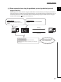
(4) Data communications using the predefined protocol (predefined protocol
support function)
Registering protocol data in advance using GX Works2 allows communications by executing only an ECPRTCL
instruction program. In addition, the protocol setting required to communicate with the connected device, such as
a measuring instrument or a bar code reader, can be configured easily using the Predefined Protocol Support
Function of GX Works2. (
Page 108, CHAPTER 11)
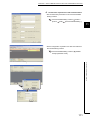
1) Setting protocols
Protocols can be set easily using the
predefined protocol support function of GX
Works2.
2) Writing protocols
Write the set protocols in the flash ROM of
the E71.
GX Works2
Sending
Connected device
E71
Receiving
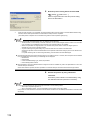
3) Executing protocols
Execute protocols by dedicated instructions.
Multiple protocols can be executed by one dedicated
instruction.
Connected device
Data can be communicated
with protocols appropriate to
each connected device.
21
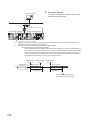
(5) Exchange of data with connected devices (communications using a fixed
buffer and random access buffer)
(a) Communications using a fixed buffer
Up to 1K-word data can be exchanged among programmable controllers or between a programmable
controller and the host system. While MC protocol communications are passive, communications using a fixed
buffer are an active protocol. If an error occurs in equipment or certain conditions are met, the programmable
controller can send data to the host system. Using an interrupt program allows the CPU module to quickly read
received data. (
Page 135, CHAPTER 12)
Sending/receiving
Another station
Sending/receiving
Own station
Connected device
(b) Communications using a random access buffer
Up to 6K-word data can be communicated. This buffer is useful when the data size is too large for
communications using a fixed buffer (capacity: 1K word). (
Reading/writing
Page 171, CHAPTER 13)
Reading/writing
E71
Connected device
Connected device
(6) Prevention of unauthorized access through a remote password
This function prevents unauthorized remote access to the CPU module. The E71 checks an entered remote
password in data communications from a connected device using remote password-protected connection.
(
22
Page 192, Section 14.3)
CHAPTER 1 FEATURES
1
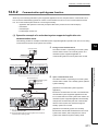
(7) E-mail sending/receiving (e-mail function)
This function sends and receives e-mails to and from a connected device in a remote location via the Internet.
For details, refer to the following.
MELSEC-Q/L Ethernet Interface Module User's Manual (Application)
(a) E-mail sending/receiving through the CPU module
The following data can be sent and received using the MSEND/MRECV instructions.
• The CPU module can receive/send up to 6K-word data from/to a personal computer or other E71 modules
as an e-mail attachment.
• The CPU module can send up to 960-word data to a personal computer or portable terminal as the main
text of an e-mail.
(b) E-mail sending using the programmable controller CPU monitoring function
Notification conditions (CPU module status or device values) that have been set using parameters are regularly
monitored. When the conditions are met, up to 960-word data can be sent by either of the following data
formats.
• Attachment
• Main text
Internet
Sending/receiving e-mails
Mail server
Mail server
E71
Connected device
23
(8) Data sending/receiving using the Web function
The system administrator can monitor a CPU module in a remote location via the Internet using a commercially
available Web browser. For details, refer to the following.
MELSEC-Q/L Ethernet Interface Module User's Manual (Web function)
HTTP
header
MC protocol
(command message)
HTTP
MC protocol
(response message)
E71
HTTP
header
Web server
HTML
ASP
Communication
library
24
Connected device
Web browser
Display of
requests/
results
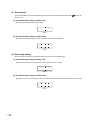
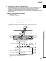
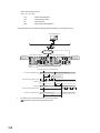
CHAPTER 2 PART NAMES
CHAPTER 2
PART NAMES
2
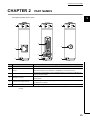
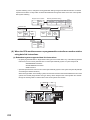
This chapter describes the E71 parts.
1)
1)
1)
3)
4)
2)
5)
6)
6)
No.
1)
2)
Name
6)
Application
LED indicator
Refer to (1) in this chapter.
10BASE-T/100BASE-TX connector
A connector to connect the E71 to the 10BASE-T or 100BASE-TX network (The E71
(RJ45)*1
determines whether to use 10BASE-T or 100BASE-TX according to the hub.)
3)
10BASE5 connector
4)
10BASE2 connector
5)
External power supply terminal
6)
Serial number display
*1
A connector to connect the E71 to the 10BASE5 network (for connecting a 10BASE5 AUI
cable (transceiver cable))
A connector to connect the E71 to the 10BASE2 network (for connecting a 10BASE2
coaxial cable)
A power supply terminal for supplying power to a transceiver in the 10BASE5 network
(13.28VDC to 15.75VDC)
A display indicating the serial number printed on the rating plate
The LED on the connector does not turn on. Depending on the serial number, the connector orientation is left-right
reversal.
25
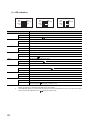
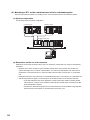
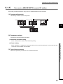
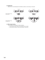
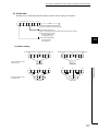
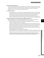
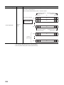
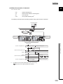
(1) LED indication
QJ71E71-100
RUN
INIT.
OPEN
SD
QJ71E71-B5
ERR.
COM.ERR.
100M
RD
QJ71E71-B2
RUN
INIT.
OPEN
SD
ERR.
COM.ERR.
RD
LED name
RUN
ERR.
COM.ERR.
RD
Description
Indicates operating status.
ON
In normal operation
OFF
An error has occurred. (
INIT.
Page 276, Section 16.4.1)
Indicates initial process status.
ON
Normal completion
OFF
Not processed
OPEN*1
Indicates open process status.
ON
OFF
SD
An open process normally completed (connection open)
An open process not completed (no connection)
Indicates whether data is being sent.
Flashing
Data being sent
OFF
Data not sent (
ERR.
Page 277, Section 16.4.3)
Indicates whether the setting is correct.
ON
OFF
COM.ERR.*2
The setting is incorrect. (
Page 276, Section 16.4.2)
Correct setting
Indicates whether a communication failure has occurred.
ON
OFF
100M
A communication failure has occurred. (
Page 276, Section 16.4.2)
Normal communications in progress
Indicates a transmission speed.
ON
100Mbps
OFF
10Mbps or a cable not connected
RD
Indicates whether data is being received.
*1
*2
ON
Data being received
OFF
Data not received (
Page 277, Section 16.4.4)
The OPEN LED turns on and off depending on the open status of user connections 1 to 16. (The open status of the
system connections (e.g. automatic open UDP port) is not included.)
If the COM.ERR. LED is on, it does not turn off even if the error cause is eliminated. For how to turn off the LED, refer to
"How to Turn Off the COM.ERR. LED". (
26
RUN
INIT.
OPEN
SD
Page 330, Section 16.8)
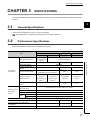
CHAPTER 3 SPECIFICATIONS
CHAPTER 3
SPECIFICATIONS
This chapter describes the performance specifications, functions, CPU module I/O signals, and buffer memory areas
of an E71.
3
3.1
General Specifications
For the general specifications of an E71, refer to the following.
"Safety Guidelines", the manual included with the CPU module or base unit
3.2
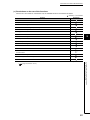
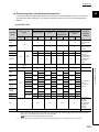
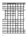
Performance Specifications
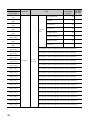
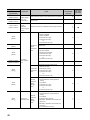
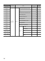
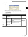
The following table lists the performance specifications of an E71.
Specifications
Item
QJ71E71-100
100BASE-TX
QJ71E71-B5
QJ71E71-B2
10BASE5
10BASE2
10BASE-T
100Mbps
Data transmission speed
(Full-duplex/Half-
10Mbps (Half-duplex)
duplex)
RJ45 (Fixed to MDI)
Transmission method
-
distance
Transmission
Maximum segment length*6
Cascade
100 modules/
30 modules/
nodes/connection*6
(maximum of 2
(maximum of 4
segment
segment
levels*1)
levels*1)
2.5m
0.5m
-
16 connections (Connections usable on a program)
Fixed buffer
1k word × 16
Random access buffer
6k words × 1
E-mail
Attachment
6k words × 1
Main text
Number of occupied I/O points
Internal current consumption (5VDC)
12VDC external power supply capacity
External dimensions
185m
(length between a hub and node)*7
connection
open connections
(Transceiver)
500m
100m
Cascade
Number of simultaneous
memory
925m
connection
nodes*6
data storage
2500m
Maximum number of
Minimum interval between
Sending/receiving
BNC
Base band
Maximum node-to-node
specifications
AUI
3.1 General Specifications
Interface
960k words × 1
32 points per slot (I/O assignment: Intelligent 32 points)
0.50A
0.50A
0.60A*2
-
*3
-
98 (H) × 27.4 (W) × 90 (D) [mm]
27
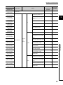
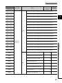
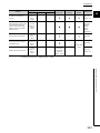
Specifications
Item
QJ71E71-100
100BASE-TX
Weight
QJ71E71-B5
QJ71E71-B2
10BASE5
10BASE2
0.12kg
0.13kg*2
10BASE-T
0.11kg
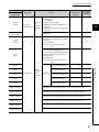
Data size
Attachment
6k words × 1
Main text
Data transfer method
960k words × 1
When sending: Send either a file as attachment or main text (select one).
When receiving: Receive a file as attachment.
Subject
Us-ASCII format or ISO-2022-JP (Base64)
Attachment format
MIME format
MIME
Version 1.0
Can be selected from binary, ASCII, and CSV.
Data of attachment format
File name: XXXX.bin (binary), XXXX.asc (ASCII), XXXX.csv (CSV)
(CSV: Comma Separated Value)
Transmission
specifications
sending/receiving
data
Cannot be divided (Only one file can be sent/received.)*4
Division of attachment
Subject: Base64/7 bits
When sending (encode)
Main text: 7 bits
Attachment: Base64
Subject: (Does not decode)
Main text: (Cannot be received)
When receiving (decode)
Attached file: Base64/7 bits/8 bits/Quoted Printable*5
Encryption
None
Compression
None
Communications with a mail
SMTP (sending server) Port number = 25,
server
POP3 (receiving server) Port number = 110
Operation check mailer
*1
*2
Microsoft® Corporation Internet Explorer 5.0 (Outlook Express 5.5/Outlook Express 5)
Netscape® Communications Corporation Netscape® 4.05
This applies when a repeater hub is used. For the number of levels that can be constructed when a switching hub is
used, consult with the manufacturer of the switching hub used.
As described below, a module with a serial number (first five digits) of "05049" or earlier has a different 5VDC internal
current consumption value and weight.
• Internal current consumption (5VDC): 0.70A
• Weight: 0.14kg
*3
*4
*5
*6
The specifications of the transceiver and the AUI cable need to be met. (
Page 70, Section 5.2.2)
If divided files are received, only the first file is received and the remaining files are discarded.
If an e-mail is sent from a connected device to the programmable controller side, specify the encoding method
(Base64/7 bits/8 bits/Quoted Printable) of the attachment.
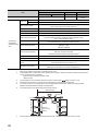
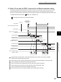
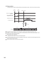
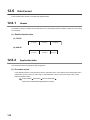
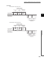
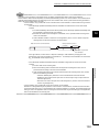
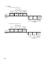
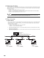
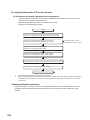
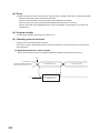
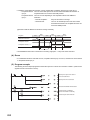
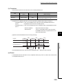
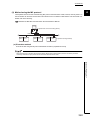
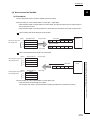
The following figure shows segment lengths and node intervals.
Segment length
Node
Transceiver
Terminating resistor
Node
Node
*7
28
Maximum
node-to-node
distance
Repeater
Node
Segment length
Segment length
Repeater
Node
For the maximum segment length (the length between hubs), consult the manufacturer of the hub used.
CHAPTER 3 SPECIFICATIONS
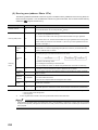
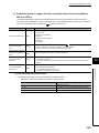
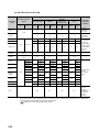
3.3
Function List
This section lists the E71 functions.
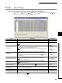
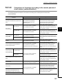
3.3.1
Function list
3
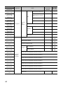
The following table lists the functions of the E71.
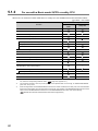
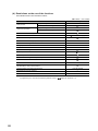
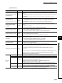
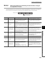
(1) Basic functions
The following table lists the basic E71 functions explained in this manual.
Function
Description
Reference
Connecting with MELSOFT
An E71 can be connected with MELSOFT products, such as a programming tool and
Page 96,
products and a GOT
MX Component, and a GOT.
CHAPTER 8
CPU module data can be read/written from/to connected devices. Access to files can
Page 99,
be also performed.
CHAPTER 9
MC protocol communications
The connected device can read/write data from/to the buffer memory or device of an
Communications using SLMP
SLMP supporting device connected to the shared network with the E71. In addition,
Page 103,
(only QJ71E71-100)
the connected device can read/write data from/to the device of the CPU module
CHAPTER 10
where an E71 is mounted.
Data communications using the
Data can be sent/received with protocols appropriate to each connected device.
predefined protocol
The connected device side protocol can be easily selected, or created/edited from
(only QJ71E71-100)
the Predefined Protocol Library of GX Works2.
Procedure
exists
using a fixed
Pairing open
buffer
Broadcast
communications
CHAPTER 11
Any data is sent/received between a CPU module and connected devices using the
Page 135,
fixed buffer of an E71.
CHAPTER 12
Paring receiving/sending connections enables data communications with two
Page 155,
connections by performing the open process for one port.
Section 12.7
Broadcast communications are enabled with all E71-mounted stations in the same
Ethernet network that is connected to the E71 when "No Procedure"
communications using a fixed buffer are performed using UDP/IP.
Page 157,
Section 12.8
Communications using a random
Data is read/written from multiple connected devices to the random access buffer of
Page 171,
access buffer
an E71.
CHAPTER 13
Data communications are performed through a router and a gateway. This function
Page 186,
is not the function where an E71 operates as a router.
Section 14.1
Communications using an auto-
Communications are enabled without the open/close processes after an E71-
Page 191,
open UDP port
mounted station is started up.
Section 14.2
Remote password
Unauthorized remote access to a CPU module is prevented.
Hub connection status monitor
The current connection status and transmission speed of an E71 and a hub and the
Page 202,
function (only QJ71E71-100)
number of times that the E71 detected disconnection can be checked.
Section 14.4
IP address in use detection
If different stations in the same network use the same IP address, the address in use
Page 203,
function (only QJ71E71-100)
can be detected.
Section 14.5
Router relay function
Network configuration in a
redundant system
Alive check function
A network can be configured in a redundant system.
Page 192,
Section 14.3
Page 205,
Section 14.6
Whether a connected device is normally operating after a connection is established
Page 225,
(open process) can be checked.
Section 14.7
An error that has occurred in an E71 can be stored in the CPU module as error
Module error collection function
history. The history data can be stored on a memory with the backup power feature;
Page 275,
(only QJ71E71-100)
therefore error details are held even if the CPU module is reset or the system is
Section 16.3
powered off.
29
3.3 Function List
3.3.1 Function list
Communications
No procedure
Page 108,
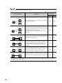
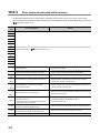
(2) Special functions
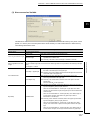
The following special functions are also available. For the functions, refer to the following.
MELSEC-Q/L Ethernet Interface Module User's Manual (Application)
Function
Description
Data are sent/received using an e-mail.
• Data sent/received by a CPU module
E-mail function
• Data sent using the programmable controller CPU monitoring function
(automatic notification function)
CC-Link IE Controller Network, CC-Link IE Field
Network, MELSECNET/H, MELSECNET/10 relay
communications
Communications using data link instructions
File transfer (FTP server) function
Data are communicated over multiple network systems where Ethernet and other
networks exist together or network systems that relay multiple Ethernet networks.
Data of a CPU module in other stations can be read/written over Ethernet using
data link instructions.
Data can be read/written in files from connected devices using an exclusive FTP
command.
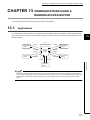
(3) Web function
This function allows data to be read/written from/to a remote CPU module over the Internet using a commercially
available Web browser. For the function, refer to the following.
MELSEC-Q/L Ethernet Interface Module User's Manual (Web function)
30
CHAPTER 3 SPECIFICATIONS
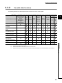
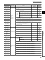
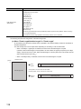
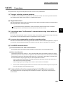
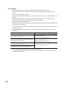
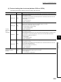
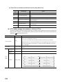
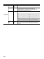
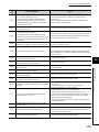
3.3.2
Use with other functions
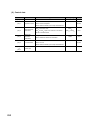
The following table lists the relationships between functions that can be used together.
: Available, ×: Not available or this function does not correspond to the functions in the "Communication function" column.
Communication function
MC protocol communications
Communications using a
fixed buffer
Communications using
SLMP
Data communications using
the predefined protocol
Communications using a
random access buffer
E-mail function
CC-Link IE
Controller Network,
CC-Link IE Field
Network,
MELSECNET/H,
MELSECNET/10
relay
communications
*1
×
Remote
password
*1
TCP
/IP
3
UDP
/IP
*3 *4
*3
×
*3
×
×
Broadcast
communications
*1 *3
×
×
×
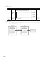
Communications
using an
auto-open
UDP port
×
×
×
×
×
×
×
×
×
×
×
×
×
×
×
×
×
×
×
×
×
×
×
These functions cannot be used with an A-compatible 1E frame.
The auto-open UDP port is excluded.
These functions can be used only for UDP/IP communication.
These functions cannot be used for communications using a fixed buffer in the "Procedure Exist" control method.
31
3.3 Function List
3.3.2 Use with other functions
*1
*2
*3
*4
Pairing
open
×
link instructions
Web function
*2
×
Communications using data
function
Alive
check
function
×
×
File transfer (FTP server)
Router
relay
function
Communication
method
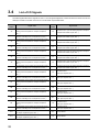
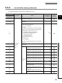
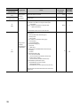
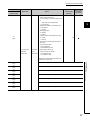
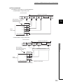
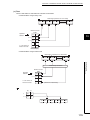
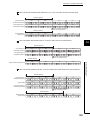
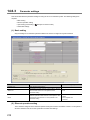
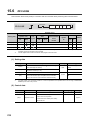
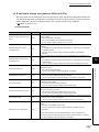
3.4
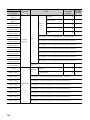
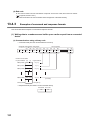
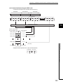
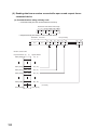
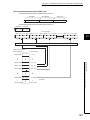
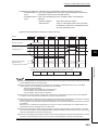
List of I/O Signals
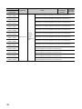
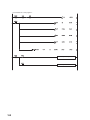
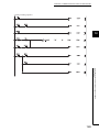
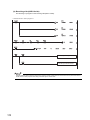
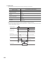
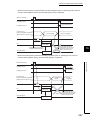
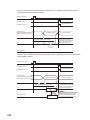
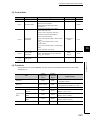
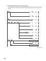
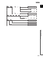
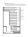
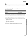
The following table lists the I/O signals for an E71. The I/O signal assignment of when the start I/O number of an E71 is
0000 (the module is mounted on the slot 0 of a main base unit) is listed below.
Device
Signal name
number
Device
For fixed buffer communication of connection No.1 (ON:
X0
Sending normal completion or reception completion,
Y0
OFF: -)
X1
For fixed buffer communication of connection No.1 (ON:
Detection of sending error or reception error, OFF: -)
Y1
For fixed buffer communication of connection No.2 (ON:
X2
Sending normal completion or reception completion,
Y2
OFF: -)
X3
For fixed buffer communication of connection No.2 (ON:
Detection of sending error or reception error, OFF: -)
Y3
For fixed buffer communication of connection No.3 (ON:
X4
Sending normal completion or reception completion,
Y4
OFF: -)
X5
For fixed buffer communication of connection No.3 (ON:
Detection of sending error or reception error, OFF: -)
Y5
For fixed buffer communication of connection No.4 (ON:
X6
Sending normal completion or reception completion,
Y6
OFF: -)
X7
For fixed buffer communication of connection No.4 (ON:
Detection of sending error or reception error, OFF: -)
Y7
For fixed buffer communication of connection No.5 (ON:
X8
Sending normal completion or reception completion,
Y8
OFF: -)
X9
For fixed buffer communication of connection No.5 (ON:
Detection of sending error or reception error, OFF: -)
Y9
For fixed buffer communication of connection No.6 (ON:
XA
Sending normal completion or reception completion,
YA
OFF: -)
XB
For fixed buffer communication of connection No.6 (ON:
Detection of sending error or reception error, OFF: -)
YB
For fixed buffer communication of connection No.7 (ON:
XC
Sending normal completion or reception completion,
YC
OFF: -)
XD
For fixed buffer communication of connection No.7 (ON:
Detection of sending error or reception error, OFF: -)
YD
For fixed buffer communication of connection No.8 (ON:
XE
Sending normal completion or reception completion,
YE
OFF: -)
XF
X10
X11
32
For fixed buffer communication of connection No.8 (ON:
Detection of sending error or reception error, OFF: -)
Open completed for connection No.1
(ON: Open completion signal, OFF: -)
Open completed for connection No.2
(ON: Open completion signal, OFF: -)
Signal name
number
YF
Connection No.1 (ON: At sending request or reception
complete confirmation signal, OFF: -)
Connection No.2 (ON: At sending request or reception
complete confirmation signal, OFF: -)
Connection No.3 (ON: At sending request or reception
complete confirmation signal, OFF: -)
Connection No.4 (ON: At sending request or reception
complete confirmation signal, OFF: -)
Connection No.5 (ON: At sending request or reception
complete confirmation signal, OFF: -)
Connection No.6 (ON: At sending request or reception
complete confirmation signal, OFF: -)
Connection No.7 (ON: At sending request or reception
complete confirmation signal, OFF: -)
Connection No.8 (ON: At sending request or reception
complete confirmation signal, OFF: -)
Connection No.1
(ON: Open request, OFF: -)
Connection No.2
(ON: Open request, OFF: -)
Connection No.3
(ON: Open request, OFF: -)
Connection No.4
(ON: Open request, OFF: -)
Connection No.5
(ON: Open request, OFF: -)
Connection No.6
(ON: Open request, OFF: -)
Connection No.7
(ON: Open request, OFF: -)
Connection No.8
(ON: Open request, OFF: -)
Y10
Use prohibited
Y11
Use prohibited
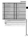
CHAPTER 3 SPECIFICATIONS
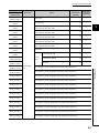
Device
Signal name
number
X12
X13
X14
X15
X16
X17
X18
X19
X1A
X1B
X1C
X1D
X1E
X1F
Open completed for connection No.3
(ON: Open completion signal, OFF: -)
Open completed for connection No.4
(ON: Open completion signal, OFF: -)
Open completed for connection No.5
(ON: Open completion signal, OFF: -)
Open completed for connection No.6
(ON: Open completion signal, OFF: -)
Open completed for connection No.7
(ON: Open completion signal, OFF: -)
Open completed for connection No.8
(ON: Open completion signal, OFF: -)
Open abnormal detection signal
(ON: At off request, OFF: -)
Open abnormal detection signal
(ON: Normal completion, OFF: -)
Open abnormal detection signal
(ON: Abnormal end, OFF: -)
Use prohibited
COM.ERR. LED lit confirmation
(ON: lit, OFF: -)
Predefined protocol ready
(ON: Ready, OFF: -)
Use prohibited
Watchdog timer error detection
(ON: Watchdog timer error, OFF: -)
Device
Signal name
number
Y12
Use prohibited
Y13
Use prohibited
Y14
Use prohibited
Y15
Use prohibited
Y16
Use prohibited
Y17
Y18
Y19
3
COM.ERR. LED Off request
(ON: At off request, OFF: -)
Use prohibited
Initial request signal
(ON: At request, OFF: -)
Y1A
Use prohibited
Y1B
Use prohibited
Y1C
Use prohibited
Y1D
Use prohibited
Y1E
Use prohibited
Y1F
Use prohibited
3.4 List of I/O Signals
Do not use any use prohibited signal as an I/O signal to the CPU module. Doing so may cause malfunction of the
programmable controller system.
Remark
The I/O signals listed in this section are mainly applied when QnA series module programs are used. For the Q series, the
I/O signals for intelligent function modules are turned on and off with dedicated instructions. When QnA series module
programs are used, it is recommended to replace the signals with the dedicated instructions described in the section that
describes the corresponding functions.
33
3.5
Buffer Memory
This section describes the E71 buffer memory.
3.5.1
Configuration of the buffer memory
This section describes a buffer memory configuration.
(1) Buffer memory address configuration
A buffer memory area consists of 16 bits per address.
b15 b14 b13 b12 b11 b10 b9 b8 b7 b6 b5 b4 b3 b2 b1 b0
(2) Buffer memory area configuration
Buffer memory consists of user areas and system areas.
(a) User areas
A user area is an area where a user writes or reads data. A user area consists of a parameter area for the initial
process and data communications, an area for data communications, and an area to store communication
status and communication error data. Data communications may take long if user areas are used continually;
therefore, use them only when needed.
(b) System areas
A system area is an area used by a system.
Do not write any data to the "system area". Doing so may cause malfunction of the programmable controller system.
34
CHAPTER 3 SPECIFICATIONS
3.5.2
List of buffer memory addresses
The following table lists the buffer memory addresses of an E71.
Address
Decimal
Initial value
Application
Name
Hexadecimal
(Decimal)
(Hexadecimal)
0 and 1
Own station E71 IP address
(0H and 1H)
2 and 3
System area
(2H and 3H)
Programming
tool setting
applicability
3
C00001FEH
-
-
Special function settings
• Router relay function (b5, b4)
00: Do not use (default)
01: Use
• Conversion system setting for CC-Link IE Controller
Network, CC-Link IE Field Network, MELSECNET/H,
MELSECNET/10 relay function (b7, b6)
00: Automatic response system (default)
4
0100H
01: IP address computation system
(4H)
10: Table exchange system
11: Use-together system
• FTP function setting (b9, b8)
00: Do not use
01: Use (default)
Bits other than those described above are reserved for
5 to 10
(5H to AH)
11
parameter
System area
area
12
(CH)
13
(DH)
14
(EH)
15
16
(10H)
17
(11H)
18
(12H)
19
(13H)
-
setting
(BH)
(FH)
3.5 Buffer Memory
3.5.2 List of buffer memory addresses
system use.
Initial process
TCP ULP timer value
3CH
(Setting time = setting value × 500 ms)
(60)
TCP zero window timer value
14H
(Setting time = setting value × 500 ms)
(20)
TCP resend timer value
14H
(Setting time = setting value × 500 ms)
(20)
TCP end timer value
28H
(Setting time = setting value × 500 ms)
(40)
IP assembly timer value
Monitoring
timer
-
AH
(Setting time = setting value × 500 ms)
(10)
Response monitoring timer value
3CH
(Setting time = setting value × 500 ms)
(60)
Destination existence confirmation starting
interval timer value
(Setting time = setting value × 500 ms)
Destination existence confirmation interval
timer value
(Setting time = setting value × 500 ms)
4B0H
(1200)
14H
(20)
Destination existence confirmation resending
3H
time
(3)
35
Address
Decimal
Initial value
Application
Name
(Decimal)
(Hexadecimal)
20
(14H)
21 to 29
(15H to 1DH)
Hexadecimal
Initial process
1388H
Auto-open UDP port number
Programming
tool setting
applicability
×
parameter
setting area
System area
-
-
TCP Maximum Segment Transmission setting area
0H: Enable TCP Maximum Segment Size Option
transmission
30
8000H: Disable TCP Maximum Segment Size
(1EH)
8000H
Option transmission
Re-initialization makes the set value effective.
Communication condition setting (Ethernet Operation
Setting) area
• Communication data code setting (b1)
0: Binary Code
1: ASCII Code
• TCP existence confirmation setting (b4)
0: Use the Ping
Initial process
parameter
setting area (For
reinitialization)
1: Use the KeepAlive
• Send frame setting (b5)
0: Ethernet
1: IEEE 802.3
• Setting of write enable/disable at RUN time (b6)
31
0: Disable
(1FH)
1: Enable
• Initial timing setting (b8)
0: Do not wait for OPEN
(Communications impossible at STOP time)
1: Always wait for OPEN
(Communication possible at STOP time)
• Reinitialization specification (b15)
0: Reinitialization process complete
(reset by the system)
1: Reinitialization process request (set by the user)
Bits other than those described above are reserved for
system use.
36
0H
×
CHAPTER 3 SPECIFICATIONS
Address
Decimal
Initial value
Application
Name
Hexadecimal
(Decimal)
(Hexadecimal)
Programming
tool setting
applicability
Connection No.1
• Usage of fixed buffer (b0)
0: For sending, or communications using
a
fixed buffer are not performed
3
1: For receiving
• Destination existence confirmation (b1)
0: No confirm
1: Confirm
• Pairing open (b7)
0: Disable
1: Enable
• Communication method (protocol) (b8)
32
0: TCP/IP
(20H)
0H
1: UDP/IP
• Fixed buffer communication procedure
(b10, b9)
00: Procedure exists
01: No procedure
10: Predefined protocol
• Open system (b15, b14)
Communication
Connection
parameter
usage
00: Active open or UDP/IP
setting area
setting area
10: Unpassive open
11: Fullpassive open
Bits other than those described above are
reserved for system use.
34
(22H)
35
(23H)
36
(24H)
37
(25H)
38
(26H)
39
(27H)
3.5 Buffer Memory
3.5.2 List of buffer memory addresses
33
(21H)
Connection No.2 (The bit configuration is the same as Connection No.1.)
Connection No.3 (The bit configuration is the same as Connection No.1.)
Connection No.4 (The bit configuration is the same as Connection No.1.)
Connection No.5 (The bit configuration is the same as Connection No.1.)
Connection No.6 (The bit configuration is the same as Connection No.1.)
Connection No.7 (The bit configuration is the same as Connection No.1.)
Connection No.8 (The bit configuration is the same as Connection No.1.)
37
Address
Decimal
Initial value
Application
Name
(Decimal)
(Hexadecimal)
40
(28H)
41 and 42
(29H and 2AH)
Connection
No.1
43
(2BH)
44 to 46
47 to 53
61 to 67
(3DH to 43H)
Communication
parameter
setting area
ation
address
82 to 88
89 to 95
96 to 102
103 and 104
(67H and 68H)
System area
-
-
System area
-
-
105
(69H)
106 and 107
(6AH and 6BH)
108 to 110
(6CH to 6EH)
(76H)
119
(77H)
38
Connection No.3 (The bit configuration is the same as Connection No.1.)
Connection No.8 (The bit configuration is the same as Connection No.1.)
(60H to 66H)
118
×
Connection No.7 (The bit configuration is the same as Connection No.1.)
(59H to 5FH)
117
FFFFFFFFFFFFH
Connection No.6 (The bit configuration is the same as Connection No.1.)
(52H to 58H)
(75H)
0H
Connection No.5 (The bit configuration is the same as Connection No.1.)
75 to 81
(74H)
Destination Port No.
Connection No.4 (The bit configuration is the same as Connection No.1.)
(4BH to 51H)
116
0H
setting area
68 to 74
111 to 115
Destination IP address
Communi-c
(44H to 4AH)
(6FH to 73H)
0H
Programming
tool setting
applicability
Connection No.2 (The bit configuration is the same as Connection No.1.)
(2FH to 35H)
54 to 60
Own station port No.
Destination MAC address
(2CH to 2EH)
(36H to 3CH)
Hexadecimal
Communication
status storage
Area for the
area
initial
process
Initial error code
0H
×
Own station IP address
0H
×
Own station MAC address
0H
×
System area
0H
Auto-open UDP port number
System area
-
-
×
-
Station number (b0 to b7)
Network number of the own station (b8 to
0H
×
0H
×
b15)
Own station group number
CHAPTER 3 SPECIFICATIONS
Address
Decimal
Initial value
Application
Name
(Decimal)
(Hexadecimal)
120
(78H)
121 and 122
(79H and 7AH)
123
(7BH)
124
(7CH)
125
(7DH)
126
127
128
129
(81H)
130 to 139
(82H to 8BH)
140 to 149
(8CH to 95H)
150 to 159
160 to 169
(A0H to A9H)
170 to 179
(AAH to B3H)
180 to 189
(B4H to BDH)
190 to 199
(BEH to C7H)
×
Destination IP address
0H
×
Destination Port No.
0H
×
Open error code
0H
×
0H
×
0H
×
0H
×
0H
×
0H
×
Connection
Fixed buffer sending error
No.1
code
time (Maximum value)
Communication
Connection
status storage
information
area
area
Fixed buffer communication
time (Minimum value)
Fixed buffer communication
time (Current value)
3
Connection No.2 (The bit configuration is the same as Connection No.1.)
Connection No.3 (The bit configuration is the same as Connection No.1.)
Connection No.4 (The bit configuration is the same as Connection No.1.)
3.5 Buffer Memory
3.5.2 List of buffer memory addresses
(96H to 9FH)
0H
Fixed buffer communication
(7FH)
Programming
tool setting
applicability
Own station port No.
Connection end code
(7EH)
(80H)
Hexadecimal
Connection No.5 (The bit configuration is the same as Connection No.1.)
Connection No.6 (The bit configuration is the same as Connection No.1.)
Connection No.7 (The bit configuration is the same as Connection No.1.)
Connection No.8 (The bit configuration is the same as Connection No.1.)
39
Address
Decimal
Initial value
Application
Name
Hexadecimal
(Decimal)
(Hexadecimal)
Programming
tool setting
applicability
LED on/off status (Stores the on/off status of
the LEDs on the front of the Ethernet
module)
• [INIT.]LED (b0)
0: OFF
1: ON (initial process completed)
• [OPEN]LED (b1)
0: OFF
1: ON (connection open processing
200
completed)
(C8H)
0H
×
0H
×
• [ERR.]LED (b3)
0: OFF
1: ON (setting error)
• [COM.ERR.]LED (b4)
0: OFF
1: ON (communication error)
Communication
Area for
status storage
module
area
status
Bits other than those described above are
reserved for system use.
Hub connection status area
• Communication mode (b9)
0: Half duplex
1: Full duplex
• Hub connection status (b10)
201
(C9H)
0: Hub not connected/disconnected
1: Hub connected
• Data transmission speed (b14)
0: Operating at 10BASE-T
1: Operating at 100BASE-TX
Bits other than those described above are
reserved for system use.
Switch status
• Operational mode setting (b1)
202
0: Online
(CAH)
1: Offline
2: Self-loopback test
3: Hardware test
40
0H
CHAPTER 3 SPECIFICATIONS
Address
Decimal
Initial value
Application
Name
Hexadecimal
(Decimal)
(Hexadecimal)
Programming
tool setting
applicability
Status of settings with a programming tool
• Communication data code setting (b1)
0: Communications in a binary code
1: Communications in an ASCII code
• Initial/open method setting (b2)
3
0: No parameter setting (start up
according to the sequence
program)
1: Parameter setting (start up
according to the parameters)
• TCP Existence confirmation setting(b4)
0: Use the Ping
1: Use the KeepAlive
• Send frame setting (b5)
203
(CBH)
Module
0: Ethernet
status area
1: IEEE 802.3
0H
• Setting of write enable/disable at RUN
time (b6)
0: Disable
1: Enable
• Initial timing setting (b8)
0: Do not wait for OPEN
Communication
(Communications impossible at
status storage
STOP time)
area
1: Always wait for OPEN
(Communication possible at STOP
time)
3.5 Buffer Memory
3.5.2 List of buffer memory addresses
Bits other than those described above are
reserved for system use.
204
System area
(CCH)
205
206
System area
(CEH)
207
sending/rec
instructions
Data link
(D0H)
instruction
209
execution
result
(D1H)
210 to 223
System area
224 to 226
System area
(E0H to E2H)
Error log area
-
×
-
0H
ZNWR instruction
System area
(D2H to DFH)
228
0H
ZNRD instruction
eiving
208
(E4H)
-
×
Area for
(CFH)
227
0H
RECV instruction execution request
(CDH)
(E3H)
-
×
-
-
-
-
Number of errors
0H
×
Error log write pointer
0H
×
41
Address
Decimal
Initial value
Application
Name
(Decimal)
(Hexadecimal)
229
(E5H)
230
(E6H)
231
(E7H)
232
(E8H)
Error log
block 1
233
(E9H)
234 and 235
(EAH and EBH)
236
(ECH)
237
238 to 246
247 to 255
256 to 264
283 to 291
(11BH to 123H)
292 to 300
(124H to 12CH)
301 to 309
(12DH to 135H)
310 to 318
(136H to 13EH)
319 to 327
(13FH to 147H)
328 to 336
(148H to 150H)
337 to 345
(151H to 159H)
346 to 354
(15AH to 162H)
355 to 363
(163H to 16BH)
364 to 372
(16CH to 174H)
42
Subheader
0H
×
Command code
0H
×
Connection No.
0H
×
Own station port No.
0H
×
Destination IP address
0H
×
Destination Port No.
0H
×
-
Error log block 4 (The bit configuration is the same as Error log block 1.)
(100H to 108H)
274 to 282
×
Error log block 3 (The bit configuration is the same as Error log block 1.)
(F7H to FFH)
(112H to 11AH)
0H
Error log block 2 (The bit configuration is the same as Error log block 1.)
(EEH to F6H)
265 to 273
Programming
tool setting
applicability
Error code/end code
System area
(EDH)
(109H to 111H)
Hexadecimal
Error log area
Error log
block area
Error log block 5 (The bit configuration is the same as Error log block 1.)
Error log block 6 (The bit configuration is the same as Error log block 1.)
Error log block 7 (The bit configuration is the same as Error log block 1.)
Error log block 8 (The bit configuration is the same as Error log block 1.)
Error log block 9 (The bit configuration is the same as Error log block 1.)
Error log block 10 (The bit configuration is the same as Error log block 1.)
Error log block 11 (The bit configuration is the same as Error log block 1.)
Error log block 12 (The bit configuration is the same as Error log block 1.)
Error log block 13 (The bit configuration is the same as Error log block 1.)
Error log block 14 (The bit configuration is the same as Error log block 1.)
Error log block 15 (The bit configuration is the same as Error log block 1.)
Error log block 16 (The bit configuration is the same as Error log block 1.)
-
CHAPTER 3 SPECIFICATIONS
Address
Decimal
Initial value
Application
Name
(Hexadecimal)
373 to 375
(175H to 177H)
System area
376 and 377
discarded due to sumcheck
(17AH and 17BH)
380 and 381
IP
382 to 397
Sent IP packet total count
System area
(17EH to 18DH)
398 and 399
400 to 407
System area
408 and 409
discarded due to sum check
(19AH and 19BH)
×
×
-
0H
×
0H
×
0H
×
0H
×
0H
×
0H
×
0H
×
error
412 and 413
Status for
Error log area
Sent ICMP packet total count
each
protocol
Echo request total count of
ICMP
received ICMP packets
Echo reply total count of sent
ICMP packets
418 and 419
Echo request total count of
(1A2H and 1A3H)
sent ICMP packets
420 and 421
Echo reply total count of
(1A4H and 1A5H)
received ICMP packets
422 to 439
System area
(1A6H to 1B7H)
440 and 441
-
Received TCP packet count
(1B8H and 1B9H)
3.5 Buffer Memory
3.5.2 List of buffer memory addresses
416 and 417
(1A0H and 1A1H)
0H
×
0H
×
0H
×
Received TCP packet count
442 and 443
446 to 471
0H
3
Received ICMP packet count
410 and 411
(1BEH to 1D7H)
×
-
Received ICMP packet count
(198H and 199H)
444 and 445
0H
0H
error detection count
(190H to 197H)
(1BCH and 1BDH)
×
-
Simultaneous transmission
(18EH and 18FH)
(1BAH and 1BBH)
0H
error
(17CH and 17DH)
(19EH and 19FH)
-
Received IP packet count
378 and 379
414 and 415
Received IP packet count
(178H and 179H)
(19CH and 19DH)
(Decimal)
Programming
tool setting
applicability
Hexadecimal
discarded due to sum check
TCP
error
Sent TCP packet total count
System area
-
-
43
Address
Decimal
Initial value
Application
Name
(Decimal)
(Hexadecimal)
472 and 473
Received UDP packet count
(1D8H and 1D9H)
discarded due to sum check
(1DAH and 1DBH)
UDP
476 and 477
478 to 481
System area
(1DEH to 1E1H)
Error log area
each
protocol
System area
492 and 493
(1ECH and 1EDH)
494 and 495
Receiving
(1EEH and 1EFH)
error
496 and 497
(1F0H and 1F1H)
498 to 511
512 and 513
(200H and 201H)
514 and 515
(202H and 203H)
516
(204H)
521 to 524
537 to 540
541 to 544
(21DH to 220H)
545 to 548
(221H to 224H)
549
(225H)
44
-
-
-
0H
×
Overflow count
0H
×
crc error count
0H
×
-
-
Default router IP address
0H
Number of registered routers
0H
Sub-net address
0H
Router IP address
0H
Router 2 (The bit configuration is the same as Router 1.)
(209H to 20CH)
(219H to 21CH)
×
0H
(207H and 208H)
533 to 536
0H
Router 1
519 and 520
(215H to 218H)
×
Sub-net mask
517 and 518
(205H and 206H)
529 to 532
0H
Framing error count
System area
(1F2H to 1FFH)
(211H to 214H)
×
Status for
(1E2H to 1EBH)
(20DH to 210H)
0H
error
Sent UDP packet total count
(1DCH and 1DDH)
525 to 528
Programming
tool setting
applicability
Received UDP packet count
474 and 475
482 to 491
Hexadecimal
Router relay
parameter
Router 3 (The bit configuration is the same as Router 1.)
setting area
Router 4 (The bit configuration is the same as Router 1.)
Router 5 (The bit configuration is the same as Router 1.)
Router 6 (The bit configuration is the same as Router 1.)
Router 7 (The bit configuration is the same as Router 1.)
Router 8 (The bit configuration is the same as Router 1.)
System area
-
-
CHAPTER 3 SPECIFICATIONS
Address
Decimal
Initial value
Application
Name
(Hexadecimal)
550 and 551
552
553 and 554
Conversion
information
(22BH and 22CH)
Station No.
System area
<-> IP
559 to 564
information
setting area
931 to 936
(The bit configuration is the same as Conversion information No.1.)
Conversion information No.64
(The bit configuration is the same as Conversion information No.1.)
Net mask pattern for CC-Link IE Controller Network,
937 and 938
MELSECNET/10 routing
939 to 943
System area
(3ABH to 3AFH)
944 to 949
(3B0H to 3B5H)
950 to 953
(3B6H to 3B9H)
955
956 to 1663
"QJ71E71"
Password
"QJ71E71"
Command input monitoring timer
System area
1664
(680H)
Fixed buffer
No.1
1665 to 2687
(681H to A7FH)
2688 to 3711
3712 to 4735
8832 to 9855
(2280H to 267FH)
AH
-
-
Data length
0H
×
Fixed buffer data
0H
×
Fixed buffer No.3 (The bit configuration is the same as Fixed buffer No.1.)
(E80H to 127FH)
7808 to 8831
708H
Fixed buffer No.2 (The bit configuration is the same as Fixed buffer No.1.)
(A80H to E7FH)
(1E80H to 227FH)
-
FTP login name
Programmable controller CPU monitoring timer
(3BCH to 67FH)
6784 to 7807
-
3.5 Buffer Memory
3.5.2 List of buffer memory addresses
FTP setting area
(3BBH)
(1A80H to 1E7FH)
0H
CC-Link IE Field Network, MELSECNET/H, and
(3A9H and 3AAH)
(1680H to 1A7FH)
-
to
(3A3H to 3A8H)
5760 to 6783
-
Conversion information No.2
to
4736 to 5759
0H
External station Ethernet module IP address
No.1
(22FH to 234H)
(1280H to 167FH)
3
0H
stations network number and station number
555 and 556
954
0H
Communication request destination/source
(229H and 22AH)
(3BAH)
-
Number of conversion table data
(228H)
557 and 558
-
System area
(226H and 227H)
(22DH and 22EH)
(Decimal)
Programming
tool setting
applicability
Hexadecimal
Fixed buffer data
area
Fixed buffer No.4 (The bit configuration is the same as Fixed buffer No.1.)
Fixed buffer No.5 (The bit configuration is the same as Fixed buffer No.1.)
Fixed buffer No.6 (The bit configuration is the same as Fixed buffer No.1.)
Fixed buffer No.7 (The bit configuration is the same as Fixed buffer No.1.)
Fixed buffer No.8 (The bit configuration is the same as Fixed buffer No.1.)
45
Address
Decimal
Initial value
Application
Name
(Decimal)
(Hexadecimal)
9856 to 16383
Shared area for
(2680H to 3FFFH)
random access
16384 to 18431
(4000H to 47FFH)
Programming
tool setting
applicability
Hexadecimal
buffers and
e-mail buffers
Shared area for random access buffers and e-mail buffers
System area
0H
×
-
-
Send/receive
18432 to 20479
(4800H to 4FFFH)
area for
predefined
Send/receive area for predefined protocol support function
0H
protocol support
function
Open completion signal
0: Open incomplete
1: Open completed
20480
• Connection No.1 (b0)
(5000H)
0H
×
-
-
0H
×
-
-
0H
×
0H
×
0H
×
• Connection No.2 (b1)
to
• Connection No.16 (b15)
20481
Connection
(5001H)
status
System area
information
Open request signal
area
0: No open request
1: Open being requested
20482
• Connection No.1 (b0)
(5002H)
• Connection No.2 (b1)
to
• Connection No.16 (b15)
Connection
20483 and 20484
(5003H and 5004H)
status storage
System area
area
Fixed buffer reception status signal
0: Data not received
20485
(5005H)
Fixed buffer
1: Data being received
information
• Connection No.1 (b0)
area
• Connection No.2 (b1)
to
• Connection No.16 (b15)
Remote password status
Remote
password
20486
status
(5006H)
storage
area
0: Unlock status/no remote password
setting
1: Lock status
• Connection No.1 (b0)
• Connection No.2 (b1)
to
• Connection No.16 (b15)
Remote password status
0: Unlock status/no remote password
Remote
20487
(5007H)
System port
information area
password
status
storage
area
setting
1: Lock status
• Auto-open UDP port (b0)
• MELSOFT application transmission port
(UDP) (b1)
• MELSOFT application transmission port
(TCP) (b2)
• FTP transmission port (b3)
46
CHAPTER 3 SPECIFICATIONS
Address
Decimal
Initial value
Application
Name
Programming
tool setting
applicability
Hexadecimal
(Decimal)
(Hexadecimal)
System port use prohibited designation
0: Use allowed
System port
20488
(5008H)
System port
information area
use
prohibited
designation
area
20489 to 20591
1: Use prohibited
• Auto-open UDP port (b0)
• MELSOFT application transmission port
×
3
(UDP) (b1)
• MELSOFT application transmission port
(TCP) (b2)
System area
(5009H to 506FH)
0H
-
-
1H
×
2H
×
0H
×
0H
×
0H
×
0H
×
0H
×
Remote password mismatch notification
accumulated count designation (For user
20592
open port)
(5070H)
0: No designation
1 or higher: Notification accumulated
count
Remote password mismatch notification
accumulated count designation (For
auto-open UDP port, MELSOFT application
20593
transmission port (TCP/ UDP) and FTP
(5071H)
transmission port)
0: No designation
1 or higher: Notification accumulated
count
20594
Accumulated count of unlock
(5072H)
process normal completion
20596
(5074H)
20597
(5075H)
20598
(5076H)
20599 to 20603
(5077H to 507BH)
20604 to 20608
(507CH to 5080H)
20609 to 20613
(5081H to 5085H)
20614 to 20618
(5086H to 508AH)
20619 to 20623
(508BH to 508FH)
20624 to 20628
(5090H to 5094H)
Accumulated count of unlock
Remote
password
Monitoring area
function
monitoring
area
process abnormal end
Connection
Accumulated count of lock
No.1
process normal completion
Accumulated count of lock
process abnormal end
Accumulated count of lock
process based on close
3.5 Buffer Memory
3.5.2 List of buffer memory addresses
20595
(5073H)
Connection No.2 (The bit configuration is the same as Connection No.1.)
Connection No.3 (The bit configuration is the same as Connection No.1.)
Connection No.4 (The bit configuration is the same as Connection No.1.)
Connection No.5 (The bit configuration is the same as Connection No.1.)
Connection No.6 (The bit configuration is the same as Connection No.1.)
Connection No.7 (The bit configuration is the same as Connection No.1.)
47
Address
Decimal
Initial value
Application
Name
(Decimal)
(Hexadecimal)
20629 to 20633
20634 to 20638
Connection No.9 (The bit configuration is the same as Connection No.1.)
(509AH to 509EH)
20639 to 20643
Connection No.10 (The bit configuration is the same as Connection No.1.)
(509FH to 50A3H)
20644 to 20648
Connection No.11 (The bit configuration is the same as Connection No.1.)
(50A4H to 50A8H)
20649 to 20653
Connection No.12 (The bit configuration is the same as Connection No.1.)
(50A9H to 50ADH)
20654 to 20658
Remote
(50AEH to 50B2H)
(50B3H to 50B7H)
20664 to 20668
(50B8H to 50BCH)
20669 to 20673
(50BDH to 50C1H)
20674 to 20678
(50C2H to 50C6H)
20679 to 20683
(50C7H to 50CBH)
20684 to 20688
(50CCH to 50D0H)
20689 to 20693
(50D1H to 50D5H)
48
Programming
tool setting
applicability
Connection No.8 (The bit configuration is the same as Connection No.1.)
(5095H to 5099H)
20659 to 20663
Hexadecimal
Connection No.13 (The bit configuration is the same as Connection No.1.)
password
Monitoring area
function
Connection No.14 (The bit configuration is the same as Connection No.1.)
monitoring
area
Connection No.15 (The bit configuration is the same as Connection No.1.)
Connection No.16 (The bit configuration is the same as Connection No.1.)
Auto-open UDP port
(The bit configuration is the same as Connection No.1.)
MELSOFT application transmission port (UDP)
(The bit configuration is the same as Connection No.1.)
MELSOFT application transmission port (TCP)
(The bit configuration is the same as Connection No.1.)
FTP transmission port
(The bit configuration is the same as Connection No.1.)
CHAPTER 3 SPECIFICATIONS
Address
Decimal
Initial value
Application
Name
(Decimal)
(Hexadecimal)
20694 to 20736
System area
(50D6H to 5100H)
20737
20738
20739
20744
20745 and 20746
Error log
(5109H and 510AH)
block 1
20747 to 20750
(510BH to 510EH)
20800 to 20806
(5140H to 5146H)
20807 to 20813
(5147H to 514DH)
20814 to 20820
(514EH to 5154H)
20821 to 20827
(5155H to 515BH)
20828 to 20834
(515CH to 5162H)
0H
×
-
-
HTTP response code
0H
×
Destination IP address
0H
×
Error time
0H
×
Status storage
area
3
Error log block 2 (The bit configuration is the same as Error log block 1.)
3.5 Buffer Memory
3.5.2 List of buffer memory addresses
20793 to 20799
(5139H to 513FH)
×
System area
(5108H)
20786 to 20792
0H
(HTTP response code 500 to 599)
20743
(5132H to 5138H)
×
Log counter
(5107H)
20779 to 20785
0H
(HTTP response code 400 to 499)
20742
(512BH to 5131H)
×
Log counter
(5106H)
20772 to 20778
0H
(HTTP response code 300 to 399)
20741
(5124H to 512AH)
×
Log counter
(5105H)
20765 to 20771
0H
(HTTP response code 200 to 299)
20740
(511DH to 5123H)
×
Log counter
(5104H)
20758 to 20764
0H
(HTTP response code 100 to 199)
(5103H)
(5116H to 511CH)
-
Log counter
(5102H)
20751 to 20757
-
Error log pointer
(5101H)
(510FH to 5115H)
Programming
tool setting
applicability
Hexadecimal
Error log block 3 (The bit configuration is the same as Error log block 1.)
Error log block 4 (The bit configuration is the same as Error log block 1.)
Error log block 5 (The bit configuration is the same as Error log block 1.)
Error log block 6 (The bit configuration is the same as Error log block 1.)
Error log block 7 (The bit configuration is the same as Error log block 1.)
Error log block 8 (The bit configuration is the same as Error log block 1.)
Error log block 9 (The bit configuration is the same as Error log block 1.)
Error log block 10 (The bit configuration is the same as Error log block 1.)
Error log block 11 (The bit configuration is the same as Error log block 1.)
Error log block 12 (The bit configuration is the same as Error log block 1.)
Error log block 13 (The bit configuration is the same as Error log block 1.)
49
Address
Decimal
Initial value
Application
Name
(Decimal)
(Hexadecimal)
20835 to 20841
Error log block 14 (The bit configuration is the same as Error log block 1.)
(5163H to 5169H)
20842 to 20848
(516AH to 5170H)
Status storage
area
20849 to 20855
20856 to 20991
Use prohibited
0: Not set
"Issue system
20993
switching
(5201H)
request at
20994
(5202H)
disconnection
detection" status
20995
20996 to 21007
-
-
1H
1: Set
Disconnection detection monitoring time
Set time = set value × 500ms (setting range: 0 to 60)
System area
4H
-
-
0H
×
-
-
storage area
Disconnection detection count
(5203H)
(5204H to 520FH)
System area
"Issue system switch in cable disconnection timeout"
20992
(5200H)
Error log block 15 (The bit configuration is the same as Error log block 1.)
Error log block 16 (The bit configuration is the same as Error log block 1.)
(5171H to 5177H)
(5178H to 51FFH)
Programming
tool setting
applicability
Hexadecimal
Use prohibited
System area
"System switching settings when communication error
occurs" (user connection)
0: Not set
21008
1: Set
(5210H)
• Connection No.1 (b0)
"System
• Connection No.2 (b1)
to
switching
settings when
21009
• Connection No.16 (b15)
communication
"System switching settings when communication error
error occurs"
occurs" (system connection)
status storage
0: Not set
area
1: Set
• Auto-open UDP port (b0)
(5211H)
0H
0H
• MELSOFT application transmission port (UDP) (b1)
• MELSOFT application transmission port (TCP) (b2)
• FTP transmission port (b3)
• HTTP port (b4)
21010 to 21119
(5212H to 527FH)
Use prohibited
0: Unique IP addresses
(5280H)
(5281H to 5283H)
IP address status
storage area
50
0
×
FFFFFFFFFFFFH
×
FFFFFFFFFFFFH
×
-
-
The MAC address of the station that has been already
connected to the network (The address is stored in the
station with the same IP address.)
The MAC address of the station with the IP address used
for another station (The address is stored in the station that
(5284H to 5286H)
21127 to 21279
-
1: Same IP address for multiple stations
21124 to 21126
(5287H to 531FH)
-
Same IP address detection flag
21120
21121 to 21123
System area
has been already connected to the network.)
Use prohibited
System area
CHAPTER 3 SPECIFICATIONS
Address
Decimal
Initial value
Application
Name
(Decimal)
(Hexadecimal)
21280 to 21283
System area
(5320H to 5323H)
-
Protocol No.
0H
×
Setting type
0H
×
Packet No.
0H
×
Element No.
0H
×
0H
×
-
-
0H
×
-
-
0H
×
-
-
0H
×
Number of protocol executions
0H
×
Protocol cancellation specification
0H
21284
21285
(5325H)
Protocol setting data error
information
21286
(5326H)
Protocol setting
21287
data check area
(5327H)
21288
Number of registered protocols
(5328H)
21289 to 21295
System area
(5329H to 532FH)
21296 to 21311
Protocol registration
(5330H to 533FH)
21312 to 21695
Use prohibited
System area
21696
Protocol execution status
(54C0H)
21697
System area
(54C1H)
21698 to 21713
(54C2H to 54D1H)
21714
(54D2H)
21715
(54D3H)
21716 to 21735
(54D4H to 54E7H)
21736 to 21755
(54E8H to 54FBH)
21756 to 21775
(54FCH to 550FH)
21776 to 21795
(5510H to 5523H)
21796 to 21815
(5524H to 5537H)
21816 to 21835
(5538H to 554BH)
21836 to 21855
(554CH to 555FH)
Connection
Received data verification result (receive
No.1
packet No.1 to 16)
3
3.5 Buffer Memory
3.5.2 List of buffer memory addresses
-
(5324H)
(5340H to 54BFH)
Programming
tool setting
applicability
Hexadecimal
Predefined
protocol support
Connection No.2 (The bit configuration is the same as Connection No.1.)
function
execution status
Connection No.3 (The bit configuration is the same as Connection No.1.)
check area
Connection No.4 (The bit configuration is the same as Connection No.1.)
Connection No.5 (The bit configuration is the same as Connection No.1.)
Connection No.6 (The bit configuration is the same as Connection No.1.)
Connection No.7 (The bit configuration is the same as Connection No.1.)
Connection No.8 (The bit configuration is the same as Connection No.1.)
51
Address
Decimal
Initial value
Application
Name
(Decimal)
(Hexadecimal)
21856 to 21875
Connection No.9 (The bit configuration is the same as Connection No.1.)
(5560H to 5573H)
21876 to 21895
Connection No.10 (The bit configuration is the same as Connection No.1.)
(5574H to 5587H)
21896 to 21915
Connection No.11 (The bit configuration is the same as Connection No.1.)
(5588H to 559BH)
21916 to 21935
(559CH to 55AFH)
21936 to 21955
(55B0H to 55C3H)
Predefined
protocol support
execution status
Connection No.14 (The bit configuration is the same as Connection No.1.)
21976 to 21995
Connection No.15 (The bit configuration is the same as Connection No.1.)
(55D8H to 55EBH)
21996 to 22015
Connection No.16 (The bit configuration is the same as Connection No.1.)
(55ECH to 55FFH)
52
Connection No.13 (The bit configuration is the same as Connection No.1.)
check area
21956 to 21975
22016 to 22559
Connection No.12 (The bit configuration is the same as Connection No.1.)
function
(55C4H to 55D7H)
(5600H to 581FH)
Programming
tool setting
applicability
Hexadecimal
Use prohibited
System area
-
-
CHAPTER 3 SPECIFICATIONS
Address
Decimal
Initial value
Application
Name
(Decimal)
(Hexadecimal)
22560
(5820H)
22561 and 22562
(5821H and 5822H)
22563
(5823H)
222564
(5824H)
22565
(5825H)
22566
22567
22568
22569
(5829H)
22570 to 22579
(582AH to 5833H)
22580 to 22589
(5834H to 583DH)
22590 to 22599
22600 to 22609
(5848H to 5851H)
22610 to 22619
(5852H to 585BH)
22620 to 22629
(585CH to 5865H)
22630 to 22639
(5866H to 586FH)
×
Destination IP address
0H
×
Destination Port No.
0H
×
Open error code
0H
×
0H
×
0H
×
0H
×
0H
×
0H
×
Connection
Fixed buffer sending error
No.9
code
time (Maximum value)
Communication
Connection
status storage
information
area
area
Fixed buffer communication
time (Minimum value)
Fixed buffer communication
time (Current value)
3
Connection No.10 (The bit configuration is the same as Connection No.9.)
Connection No.11 (The bit configuration is the same as Connection No.9.)
Connection No.12 (The bit configuration is the same as Connection No.9.)
3.5 Buffer Memory
3.5.2 List of buffer memory addresses
(583EH to 5847H)
0H
Fixed buffer communication
(5827H)
Programming
tool setting
applicability
Own station port No.
Connection end code
(5826H)
(5828H)
Hexadecimal
Connection No.13 (The bit configuration is the same as Connection No.9.)
Connection No.14 (The bit configuration is the same as Connection No.9.)
Connection No.15 (The bit configuration is the same as Connection No.9.)
Connection No.16 (The bit configuration is the same as Connection No.9.)
53
Address
Decimal
Initial value
Application
Name
(Decimal)
(Hexadecimal)
22640
22641
22642
22643
(5873H)
22644
(5874H)
22645
(5875H)
22646
(5876H)
E-mail status
22647
storage area
22648
0H
×
Dedicated instruction abnormal end count
0H
×
Normal receiving count
0H
×
Attached file receiving count
0H
×
Server inquiry count
0H
×
Server communication error count
0H
×
Error log write count
0H
×
Receiving error log write pointer
0H
×
Error code
0H
×
Command code
0H
×
From
0H
×
Date
0H
×
Subject
0H
×
count
(5872H)
(5878H)
×
Dedicated instruction normal completion
(5871H)
Receive
22649
(5879H)
22650
(587AH)
22651 to 22658
(587BH to 5882H)
22659 to 22662
(5883H to 5886H)
22663 to 22692
(5887H to 58A4H)
54
Programming
tool setting
applicability
0H
Number of mails remaining on the server
(5870H)
(5877H)
Hexadecimal
Error log
block 1
CHAPTER 3 SPECIFICATIONS
Address
Decimal
Initial value
Application
Name
(Decimal)
(Hexadecimal)
22693 to 22736
22737 to 22780
Error log block 3 (The bit configuration is the same as Error log block 1.)
(58D1H to 58FCH)
22781 to 22824
22825 to 22868
Error log block 5 (The bit configuration is the same as Error log block 1.)
(5929H to 5954H)
22869 to 22912
Error log block 6 (The bit configuration is the same as Error log block 1.)
(5955H to 5980H)
22913 to 22956
Error log block 7 (The bit configuration is the same as Error log block 1.)
(5981H to 59ACH)
22957 to 23000
Error log block 8 (The bit configuration is the same as Error log block 1.)
(59ADH to 59D8H)
23001 to 23044
Receive
(59D9H to 5A04H)
23045 to 23088
23089 to 23132
Error log block 11 (The bit configuration is the same as Error log block 1.)
(5A31H to 5A5CH)
23133 to 23176
Error log block 12 (The bit configuration is the same as Error log block 1.)
(5A5DH to 5A88H)
E-mail status
storage area
Error log block 13 (The bit configuration is the same as Error log block 1.)
23221 to 23264
Error log block 14 (The bit configuration is the same as Error log block 1.)
(5AB5H to 5AE0H)
23265 to 23308
Error log block 15 (The bit configuration is the same as Error log block 1.)
(5AE1H to 5B0CH)
23309 to 23352
Error log block 16 (The bit configuration is the same as Error log block 1.)
(5B0DH to 5B38H)
23353
Dedicated instruction normal completion
(5B39H)
23354
23355
(5B3BH)
23356
23359
(5B3FH)
23360
(5B40H)
0H
×
Dedicated instruction abnormal end count
0H
×
Number of mails normally completed
0H
×
Attached file sending count
0H
×
Sending to the server count
0H
×
Number of mails abnormally completed
0H
×
Error log write count
0H
×
Sending error log write pointer
0H
×
count
(5B3AH)
23358
3.5 Buffer Memory
3.5.2 List of buffer memory addresses
23177 to 23220
(5A89H to 5AB4H)
(5B3EH)
Error log block 9 (The bit configuration is the same as Error log block 1.)
Error log block 10 (The bit configuration is the same as Error log block 1.)
(5A05H to 5A30H)
23357
3
Error log block 4 (The bit configuration is the same as Error log block 1.)
(58FDH to 5928H)
(5B3DH)
Programming
tool setting
applicability
Error log block 2 (The bit configuration is the same as Error log block 1.)
(58A5H to 58D0H)
(5B3CH)
Hexadecimal
Send
55
Address
Decimal
Initial value
Application
Name
(Decimal)
(Hexadecimal)
23361
(5B41H)
23362
(5B42H)
23363 to 23370
Error log
(5B43H to 5B4AH)
block 1
23371 to 23374
(5B4BH to 5B4EH)
23375 to 23404
(5B4FH to 5B6CH)
23405 to 23448
23449 to 23492
E-mail status
(5B99H to 5BC4H)
storage area
23537 to 23580
23581 to 23624
23625 to 23668
23669 to 23712
23713 to 24575
24576
Fixed buffer
No.9
24577 to 25599
(6001H to 63FFH)
25600 to 26623
26624 to 27647
0H
×
Subject
0H
×
-
-
Data length
0H
×
Fixed buffer data
0H
×
Fixed buffer No.11 (The bit configuration is the same as Fixed buffer No.9.)
(6800H to 6BFFH)
56
Date
Fixed buffer No.10 (The bit configuration is the same as Fixed buffer No.9.)
(6400H to 67FFH)
31744 to 32767
×
System area
(6000H)
(7C00H to 7FFFH)
0H
Error log block 8 (The bit configuration is the same as Error log block 1.)
(5CA1H to 5FFFH)
30720 to 31743
To
Error log block 7 (The bit configuration is the same as Error log block 1.)
(5C75H to 5CA0H)
(7800H to 7BFFH)
×
Error log block 6 (The bit configuration is the same as Error log block 1.)
(5C49H to 5C74H)
29696 to 30719
0H
Error log block 5 (The bit configuration is the same as Error log block 1.)
(5C1DH to 5C48H)
(7400H to 77FFH)
Command code
Error log block 4 (The bit configuration is the same as Error log block 1.)
(5BF1H to 5C1CH)
28672 to 29695
×
Error log block 3 (The bit configuration is the same as Error log block 1.)
23493 to 23536
(7000H to 73FFH)
0H
Send
(5BC5H to 5BF0H)
27648 to 28671
Error code
Error log block 2 (The bit configuration is the same as Error log block 1.)
(5B6DH to 5B98H)
(6C00H to 6FFFH)
Programming
tool setting
applicability
Hexadecimal
Fixed buffer data
area
Fixed buffer No.12 (The bit configuration is the same as Fixed buffer No.9.)
Fixed buffer No.13 (The bit configuration is the same as Fixed buffer No.9.)
Fixed buffer No.14 (The bit configuration is the same as Fixed buffer No.9.)
Fixed buffer No.15 (The bit configuration is the same as Fixed buffer No.9.)
Fixed buffer No.16 (The bit configuration is the same as Fixed buffer No.9.)
CHAPTER 4 PROCEDURES BEFORE OPERATION
CHAPTER 4
PROCEDURES BEFORE OPERATION
This chapter describes how to connect an E71 to Ethernet. For how to communicate with connected devices after the
E71 is connected, refer to the communication procedure. (
Page 78, CHAPTER 7)
Checkbox
System planning
Plan the system configuration of the E71.
Mounting
Mount the E71 on the base unit.
Wiring
Connect an Ethernet cable to the E71.
Setting parameters
Set the following parameters, which are required to start up
the E71, on a programming tool.
Basic setting
Ethernet operation setting
Restarting the CPU module
Reflect the parameter settings by powering off and on the CPU
module or resetting the CPU module.
Page 27, CHAPTER 3,
Page 59, CHAPTER 5
Page 25, CHAPTER 2,
Page 72, Section 6.1
Page 68, Section 5.2,
Page 73, Section 6.2
Page 80, Section 7.1.2,
Page 81, Section 7.1.3
QCPU User's Manual
(Hardware Design,
Maintenance and
Inspection)
Network diagnostics
Page 354, Appendix 5
Check that the cables are connected properly or that
communications are performed normally with the set
parameters. (PING test, loopback test)
Continued to COMMUNICATION PROCEDURE
57
4
Memo
58
CHAPTER 5 SYSTEM CONFIGURATION
CHAPTER 5
SYSTEM CONFIGURATION
This chapter describes the system configuration of an E71.
5.1
Configuration of an E71-mounted System
This section describes the configuration of the system where an E71 is mounted.
5.1.1
5
Applicable modules and base units, and the number of
connectable modules
(1) Connecting an E71 to a CPU module
For the CPU modules and base units that can be used for an E71 and the number of connectable modules, refer
to the following.
User’s Manual (Hardware Design, Maintenance and Inspection) for the CPU module used.
(2) Connecting an E71 in a MELSECNET/H remote I/O station
For the base units that can be used for an E71 and the number of connectable modules, refer to the following.
Q Corresponding MELSECNET/H Network System Reference Manual (Remote I/O network)
5.1 Configuration of an E71-mounted System
5.1.1 Applicable modules and base units, and the number of connectable modules
59
5.1.2
For use with a Basic model QCPU or safety CPU
When an E71 is mounted to a Basic model QCPU or a safety CPU, the available functions are restricted as follows.
: Available, ×: Not available
Availability
Function
Basic model
QCPU
Safety CPU
Connection with MELSOFT products and a GOT
MC protocol communications
Communications using SLMP
Data communications using the predefined protocol
×
*2
Communications using a fixed buffer
Receive process using an interrupt program
*1
×
Pairing open
Broadcast communications
Communications using a random access buffer
Remote password
×
*1
Router relay function
Communications using an auto-open UDP port
Connected device alive check function
E-mail function
*1
CC-Link IE Controller Network, CC-Link IE Field Network, MELSECNET/H,
×
MELSECNET/10 relay communications
Communications using data link instructions
Receive process using an interrupt program
*3
*1
*3
×
File transfer (FTP server function)
×
Web function
×
*1
*2
*3
This function can be used in a Basic model QCPU with the function version B or later. For the version of a programming
tool, check the corresponding software version. (
Page 420, Appendix 11.1)
The connection numbers 1 to 8 only can be specified. If the specified value is out of range, an "OPERATION ERROR"
(error code: 4101) occurs.
When the target station of the SREAD/SWRITE instructions is a Basic model QCPU or safety CPU, the read notification
device to the target station set to the argument (D3) is ignored. The operation of the SREAD/SWRITE instructions is the
same as that of the READ/WRITE instructions. For the SREAD/SWRITE instructions, refer to the following.
MELSEC-Q/L Ethernet Interface Module User's Manual (Application)
60
×
CHAPTER 5 SYSTEM CONFIGURATION
5.1.3
For use in a multiple CPU system
When using an E71 in a multiple CPU system, refer to the following.
QCPU User's Manual (Multiple CPU System)
(1) Precautions
Note the following precautions for when using an E71 in a multiple CPU system.
(a) Writing network parameters
Configure network parameters only on the control CPU of an E71.
(b) Accessing an E71 non-control CPU from a connected device
When accessing a non-control CPU in a multiple CPU system, use an E71 with the function version B or later.
5
E71
Non-control CPU
Control CPU
Connected device
(c) Accessing other stations
A control CPU and non-control CPU in a station to be accessed are accessible even when a relay station or
station to be accessed is configured in a multiple CPU system. To access a non-control CPU, use modules of
accessed and CPU modules.
Ex. When the relay modules are CC-Link IE Controller Network modules
Own
station
CC-Link IE
Controller Network
Programming tool
Connected device
Relay
station
CC-Link IE
Controller Network
Station to be
accessed
61
5.1 Configuration of an E71-mounted System
5.1.3 For use in a multiple CPU system
the function version B or later in the own station and all relay stations and for all relay modules in stations to be
5.1.4
For use in a redundant system
When using an E71 in a redundant system, refer to the following.
QnPRHCPU User's Manual (Redundant System)
(1) Mounting an E71 on the main base unit of a redundant system
This section provides information on mounting an E71 on the main base unit of a redundant system.
(a) Basic system configuration
Access can be performed from a connected device to the control system and standby system of a redundant
system.
(b) System configuration with a communication path backed up
Access can be performed from a connected device to the control system and standby system of the redundant
system in the communication path 1 or communication path 2.
Ex. If a communication error occurs during access to the control system through the communication path 1
(1) in the figure below), the control system can be accessed through the communication path 2 (2) in the
figure below). If a communication error also occurs in the communication path 2, the system switches
between the control system and the standby system, enabling communications with the new system (3) in
the figure below).
Connected device
Ethernet
network No.1
Control system
1)
Ethernet
network No.2
2)
Standby system
Tracking cable
62
3)
: Communication path 1
: Communication path 2
CHAPTER 5 SYSTEM CONFIGURATION
(c) Restrictions on the use of the functions
When an E71 is mounted on a main base unit, the available functions are restricted as follows.
: Available, ×: Not available
Function
Availability
Connection with MELSOFT products and a GOT
MC protocol communications
*1
Communications using SLMP
Data communications using the predefined protocol
Communications using a fixed buffer
*1
Pairing open
Broadcast communications
*1
Communications using a random access buffer
*1
5
Remote password
Router relay function
Communications using an auto-open UDP port
Connected device alive check function
E-mail function
CC-Link IE Controller Network, CC-Link IE Field Network, MELSECNET/H, MELSECNET/10 relay
communications
*1
*1
Communications using data link instructions
*1
File transfer (FTP server function)
*1
Web function
Available with restrictions. For the restrictions, refer to the functions that can be used in a redundant system.
(
5.1 Configuration of an E71-mounted System
5.1.4 For use in a redundant system
*1
Page 215, Section 14.6.4)
63
(2) Mounting an E71 on the extension base unit of a redundant system
This section provides information on mounting an E71 on the extension base unit of a redundant system.
(a) System configuration
The following shows the system configuration.
Control system
Standby system
Tracking cable
Extension cable
Extension base unit
Ethernet
Connected device
(b) Restrictions on the use of the functions
Restrictions are the same as those of when an E71 is mounted on a main base unit, except for the following
restrictions.
• Because an E71 does not issue a system switching request to the control system CPU module, the
system switching does not continue communications. To continue communications even when the E71
experiences a communication error or when the cable is disconnected, mount the E71 on a main base
unit.
• Dedicated instructions cannot be used. To use dedicated instructions, mount the E71 on a main base unit.
• The following restrictions apply to communications via modules mounted on an extension base unit.
• An access destination that can be specified (a control system CPU module or standby system
CPU module or a system A CPU module or system B CPU module) varies according to the MC
protocol dedicated command.
• If systems are switched during MC protocol communications or communications using dedicated
instructions from other stations, a communication timeout may occur.
64
CHAPTER 5 SYSTEM CONFIGURATION
5.1.5
For use in a MELSECNET/H remote I/O station
This section provides information on using an E71 in a MELSECNET/H remote I/O station.
(1) System configuration
The following shows the system configuration.
Remote master station
Remote I/O station
5
Connected device
MELSECNET/H remote I/O network
Remote I/O station
(2) Parameter settings
Configure the network parameters as follows.
(a) Ethernet operation setting
Select "Always wait for OPEN" for the initial timing setting.
Select "Unpassive" or "Fullpassive" in the open system for the TCP/IP communication. An auto-open UDP port
can be also used for UDP/IP communication.
(3) Open/close processes
Perform the open/close processes on the connected device side.
65
5.1 Configuration of an E71-mounted System
5.1.5 For use in a MELSECNET/H remote I/O station
(b) Open setting
(4) Restrictions on the use of the functions
The available functions are restricted as follows.
: Available, ×: Not available
Function
Initial process
Open/close processes
Availability
Program setting
×
Network parameter setting
Program setting
×
Network parameter setting
Connection with MELSOFT products and a GOT
MC protocol communications
(Refer to clause (5).)
Communications using SLMP
Data communications using the predefined protocol
×
Communications using a fixed buffer
×
Pairing open
×
Broadcast communications
×
Communications using a random access buffer
*1
Remote password
Router relay function
Communications using an auto-open UDP port
Connected device alive check function
E-mail function
×
CC-Link IE Controller Network, CC-Link IE Field Network, MELSECNET/H,
MELSECNET/10 relay communications
Communications using data link instructions
×
Web function
×
*1
This function can be used in a MELSECNET/H remote I/O station with the function version D or later. For the version of
a programming tool, check the corresponding software version. (
66
× (Can be relayed)
File transfer (FTP server function)
Page 420, Appendix 11.1)
CHAPTER 5 SYSTEM CONFIGURATION
(5) Access using MC protocol communications
Access to a MELSECNET/H remote I/O station using the MC protocol and access to other stations via a
MELSECNET/H remote I/O station are described below.
(a) Compatible frames
Use a QnA-compatible 3E frame or 4E frame for communications. (An A-compatible 1E frame cannot be used.)
(b) Available functions
The following functions can be used in MELSECNET/H remote I/O stations.
• Reading/writing of device memory*1 *2
• Reading/writing of buffer memory*2
• Reading/writing of intelligent function module buffer memory
*1
For accessible MELSECNET/H remote I/O station devices, refer to the following.
*2
MELSEC-Q/L MELSEC Communication Protocol Reference Manual
This function cannot be used in QnA/A series-compatible MELSECNET/10 remote I/O stations.
5
(c) Access to other stations through MELSECNET/H remote I/O stations
A MELSECNET/H remote master station and MELSECNET/H remote I/O stations can be accessed.
Ex. The MELSECNET/H remote master station and MELSECNET/H remote I/O stations can be accessed
from a connected device.
Connected device
1)
MELSECNET/H remote I/O network
Access allowed
Access not allowed
2)
The following methods cannot be used to access other stations through MELSECNET/H remote I/O
stations.
• Access to other stations from a MELSECNET/H remote master station via the E71 connected in
a MELSECNET/H remote I/O station (1) in the figure above)
• Access to other stations through two E71 modules (2) in the figure above)
67
5.1 Configuration of an E71-mounted System
5.1.5 For use in a MELSECNET/H remote I/O station
Remote master station
5.2
Network Components
This section describes the devices used for Ethernet.
5.2.1
Configuration devices used for 100BASE-TX/10BASE-T
connection
A QJ71E71-100 is used for 100BASE-TX and 10BASE-T connections. An E71 determines whether to use 10BASE-T
or 100BASE-TX and the full-duplex or half-duplex transmission mode according to the hub. For connection to the hub
without the automatic negotiation function, set the half-duplex mode on the hub side.
(1) 100BASE-TX connection
To configure a system for 100BASE-TX connection, use devices that meet the IEEE 802.3 100 BASE-TX
standards.
Connected device
E71
Hub
Configuration device
Straight cable
A Category 5 or higher straight cable is usable.
System operation using connection with a cross cable is not
Shielded twisted pair
cable (STP)
Description
Cross cable
guaranteed. Note, however, that a Category 5 or 5e cross cable can be
used for data communications with an E71 (between QJ71E71-100
modules) or connection with a GOT.
Connector
RJ45 connector
Hub
100Mbps hub
*1
68
Up to two levels of cascade connection can be configured.*1
This applies when a repeater hub is used. For the number of levels that can be constructed when a switching hub is
used, consult with the manufacturer of the switching hub used.
CHAPTER 5 SYSTEM CONFIGURATION
During high-speed communications (100Mbps) using 100BASE-TX connection, a communication error may occur due to
high-frequency noise from devices other than a programmable controller in a given installation environment. The following
describes countermeasures to be taken on the E71 side to avoid high-frequency noise influence.
• Wiring connection
• Do not bundle the cable with the main circuit or power cable or do not place it near those lines.
• Put the cable in a duct.
• Communication method
• Use TCP/IP for data communications with connected devices.
• Increase the number of retries of communications if needed.
• 10Mbps communications
• Use a 10Mbps hub for the E71 and set the data transmission speed to 10Mbps.
• Change the transmission speed of the E71 to 10Mbps using the UINI instruction. (
Page 267,
Section 15.13)
5
Remark
Consult a network specialist for required devices.
(2) 10BASE-T connection
To configure a system for 10BASE-T connection, use devices that meet the IEEE 802.3 10BASE-T standards.
Connected device
E71
Configuration device
Unshielded twisted
Straight cable
System operation using connection with a cross cable is not
pair cable (UTP) or
shielded twisted pair
Cross cable
cable (STP)
guaranteed. Note, however, that a Category 3, 4, or 5 cross cable can
be used for data communications with an E71 (between QJ71E71-100
modules) or connection with a GOT.
Connector
RJ45 connector
Hub
10Mbps hub
*1
Description
A Category 3, 4, or 5 straight cable is usable.
Up to four levels of cascade connection can be configured.*1
This applies when a repeater hub is used. For the number of levels that can be constructed when a switching hub is
used, consult with the manufacturer of the switching hub used.
Remark
Consult a network specialist for required devices.
69
5.2 Network Components
5.2.1 Configuration devices used for 100BASE-TX/10BASE-T connection
Hub
5.2.2
Configuration devices used for 10BASE5 connection
A QJ71E71-B5 is used for 10BASE5 connection. Use devices that meet the IEEE 802.3 10BASE5 standards.
N-type terminating
resistor
N-type terminating
resistor
Coaxial cable
Transceiver
Connected device
E71
DC power supply
Configuration device
Description
10BASE5 coaxial cable
N-type terminating resistor
The Ethernet standards need to be satisfied.
AUI cable (transceiver cable)
Transceiver
DC power supply (power supply for a
transceiver)
The Ethernet standards need to be satisfied. The SQE TEST (Signal Quality
Error TEST) or the heartbeat needs to be supported.
The specifications of the transceiver and the AUI cable need to be satisfied.
● The transceiver electrical characteristics are as follows. The power supply for the transceiver needs to be 13.28VDC to
15.75VDC.
• Input terminal voltage: 12VDC-6% to 15VDC+5%
• AUI cable direct resistance: 40/km or less, maximum length 50m (164ft.)
• Maximum current consumption: 500mA or less
The voltage drop (V) of the power supply for the transceiver is calculated as follows.
Voltage drop (V) = AUI cable direct current resistance (/m) × AUI cable length (m) × 2 (both directions) × transceiver
current consumption (A)
Ex. 2.0(VDC) = 0.04(/m) × 50(m) × 2 × 0.5(A)
In this case, the recommended power supply for the transceiver is more than 13.28VDC.
13.28(VDC) = 12VDC-6% × (11.28VDC) + 2.0(VDC)
● A communication error may occur due to high-frequency noise from devices other than a programmable controller in a
given installation environment. The following describes countermeasures to be taken on the E71 side to avoid highfrequency noise influence.
• Install a ferrite core. (
Page 74, Section 6.2.2)
• Increase the number of retries of communications for TCP/IP communication.
Remark
Consult a network specialist for required devices.
70
CHAPTER 5 SYSTEM CONFIGURATION
5.2.3
Configuration devices used for 10BASE2 connection
A QJ71E71-B2 is used for 10BASE2 connection. Use devices that meet the IEEE 802.3 10BASE2 standards.
Terminating
resistor
Terminating
resistor
Coaxial cable
T-type
connector
Connected device
E71
Configuration device
Description
RG58A/U or RG58C/U (coaxial cable 50)
BNC-type terminating resistor
T-type connector
5
-
Product equivalent to 221629-4 manufactured by Tyco Electronics
AMP K.K.
Product equivalent to UG-274/U(15) manufactured by Hirose
Electric Co., Ltd.
Remark
Consult a network specialist for required devices.
5.2 Network Components
5.2.3 Configuration devices used for 10BASE2 connection
71
CHAPTER 6
INSTALLATION AND WIRING
This chapter describes installation and wiring of the E71.
6.1
Installation
This section describes installation of the E71.
(1) Installation method
For details on installation of the E71, refer to the following.
QCPU User's Manual (Hardware Design, Maintenance and Inspection)
(2) Handling precautions
The precautions for handling the E71 are described below.
• Do not drop or apply strong shock to the E71 case since it is made from resin.
• Tighten screws such as module fixing screws within the following range.
Screw
External power supply terminal screw
*2
Module fixing screw (M3)
*1
*2
72
Tightening torque range
(M2.5)*1
0.40N•m
0.36 to 0.48N•m
This terminal is an external power input terminal for supplying power to a transceiver when the E71 is connected to the
10BASE5 network.
A module can be easily fixed onto the base unit using the hook at the top of the module. However, it is recommended to
secure the module with the module fixing screw if the module is subject to significant vibration.
CHAPTER 6 INSTALLATION AND WIRING
6.2
Wiring
This section describes Ethernet cable wiring and wiring precautions. For a network configuration and cables and hubs
used, refer to "SYSTEM CONFIGURATION". (
6.2.1
Page 59, CHAPTER 5)
Wiring with the QJ71E71-100
The following describes connection and disconnection of the Ethernet cable.
6
1.
Check the orientation of the connector and insert the Ethernet cable connector into the E71 until it
clicks into place.
(2) Disconnecting the cable
1.
While holding down the Ethernet cable tab, pull out the cable.
73
6.2 Wiring
6.2.1 Wiring with the QJ71E71-100
(1) Connecting the cable
6.2.2
Wiring with the QJ71E71-B5
The following describes connection and disconnection of the AUI cable and connection of the external power supply
terminal.
Retainer
A
B
AUI cable
External power supply terminal
(DC power supply for a transceiver)
(1) Connecting the cable
1.
2.
Slide the retainer in the orientation A and insert the AUI cable connector all the way in.
Slide the retainer in the orientation B and make sure that the AUI cable is securely locked into
place.
3.
Connect the external power supply terminal (DC power supply for a transceiver).
Strip the cable jacket by 13mm.*1 The applicable cable size is 0.13mm2 to 2.5mm2 (26AWG to 14AWG).
13mm
4.
5.
*1
74
Loosen the terminal screw and insert the cable into the terminal.
Tighten the terminal screw within the torque range listed in Section 6.1 (2).
If the wire strip length is too long, the conductive part is exposed and it may increase the risk of electric shock or shortcircuit between the adjacent terminals. If the wire strip length is too short, it may result in poor contact.
CHAPTER 6 INSTALLATION AND WIRING
To prevent the influence of high-frequency noise using ferrite cores, install them on the E71 side, connected device side, and
transceiver side on the AUI cable. (Ferrite core used for the tests conducted by Mitsubishi Electric Corporation: ZCAT 20320930 from TDK Corporation)
QJ71E71-B5
AUI cable
10BASE5 coaxial cable
Ferrite core
6
Transceiver
(2) Disconnecting the cable
1.
2.
Slide the retainer in the orientation A, hold the connector on the AUI cable, and pull out the cable.
Slide the retainer in the orientation B.
6.2 Wiring
6.2.2 Wiring with the QJ71E71-B5
75
6.2.3
Wiring with the QJ71E71-B2
The following describes connection and disconnection of the coaxial cable.
[2]
[1]
(1) Connecting the cable
1.
2.
3.
Align the groove [1] with the groove [2] and push the connector in.
While pushing the connector in, rotate it one-quarter clockwise until it securely locks into place.
Check that the connector is locked.
(2) Disconnecting the cable
1.
76
Rotate the connector one-quarter counterclockwise and pull out the connector.
CHAPTER 6 INSTALLATION AND WIRING
Remark
● The following shows the composition of the BNC connector and coaxial cable.
• Parts comprising the BNC connector
• Structure of the coaxial cable
External conductor
Outer sheath Insulator
Washer
Nut
Gasket
Internal conductor
Plug shell
Clamp
Contact
● The following shows how to attach the BNC connector and the coaxial cable.
1. Cut off the outer sheath of the coaxial cable by the length shown in
10mm
6
the figure to left. Take care not to damage the external conductor.
Cut off this portion of the outer sheath.
Clamp
2. Fix the nut, washer, gasket, and clamp to the coaxial cable as
shown in the figure to left and unfasten the external conductor.
Nut
Washer
Gasket
3. Cut the external conductor, insulator, and internal conductor by the
length shown in the figure to left. Cut off the external conductor to
the same length as that of the tapered section of the clamp, and
5mm
smooth it down to the clamp.
7mm
Clamp and external conductor
4. Solder the contact to the internal conductor. Note the following.
Solder the contact.
• Make sure that the soldered part does not swell.
• Make sure that there is no gap between the connector and the
cable insulator and they do not cut into each other.
• To prevent the insulator from deformation, solder the contact
quickly.
5. Insert the contact assembled in the step 4. into the plug shell
and screw the nut into the plug shell.
77
6.2 Wiring
6.2.3 Wiring with the QJ71E71-B2
Insulator
Internal conductor
CHAPTER 7
COMMUNICATION PROCEDURE
This chapter describes the procedure for communicating with connected devices after the E71 is connected to
Ethernet. For the procedure for connecting the E71 to Ethernet, refer to "PROCEDURES BEFORE OPERATION".
(
Page 57, CHAPTER 4)
Continued from PROCEDURES BEFORE OPERATION
Parameter settings
Set parameters other than the basic setting and Ethernet
operation setting when required.
Page 79, Section 7.1,
Parameter setting of each
function
Starting the CPU module
Update the settings by powering off and on the CPU module
or resetting the CPU module.
QCPU User's Manual
(Hardware Design,
Maintenance and Inspection)
Initial process
The process is automatically performed with default settings
of the parameters.
Open process
Page 85, Section 7.2,
Establish connections with connected devices.
Page 93, Section 7.3
Data communications
using each function
Close process
Disconnect (cancel) connections with the connected devices
where connections have been established by the open process.
78
Page 85, Section 7.2,
Page 93, Section 7.3
CHAPTER 7 COMMUNICATION PROCEDURE
7.1
Setting Parameters Required for Communications
This section describes how to set parameters to communicate between the E71 and connected devices.
7.1.1
Parameter list
The following table lists parameters set through a programming tool.
Item
Description
Reference
Network Type
Start I/O No.
Basic setting
Network No.
Station No.
Configure settings to use the E71 as a network
module.
Page 80, Section 7.1.2
Mode
Operation Setting
Configure the settings, such as an IP address, to
connect the E71 to Ethernet.
Initial Setting
Set a data communication timer value.
Open Setting
Configure connection settings.
Page 81, Section 7.1.3
Page 344, Appendix 4.1
7
Page 83, Section 7.1.4,
Parameter setting of each
function
Router Relay Parameter
Configure settings to communicate with connected
devices on Ethernet via a router and a gateway.
Configure settings (e.g. network number and
Network
Parameter
FTP Parameters
E-mail Setting
Interrupt Settings
Redundant settings
Routing Parameters
station number) to communicate with other network
MELSEC-Q/L Ethernet
modules.
Interface Module User's
Configure the settings of the file transfer (FTP)
Manual (Application)
function.
Configure the settings of the e-mail function and the
automatic notification function.
Set the control number (SI) on the E71 side to
request an interrupt to the CPU module.
Configure settings to use the E71 on the main base
unit in a redundant system.
Set the communication path to communicate with a
station having a different network number.
Page 146, Section 12.5.1
Page 212, Section 14.6.3
MELSEC-Q/L Ethernet
Interface Module User's
Manual (Application)
When two communication paths are configured
Group Settings
between the connected device and the E71 on the
QnPRHCPU User's
main base unit in a redundant system, configure
Manual (Redundant
settings to disable system switching even if an error
System)
occurs in either communication path.
Valid Module During Other Station
Access
Select a relay module when an access request with
no network number specified is issued from
-
another station.
The connected device side protocol can be easily
Predefined Protocol Support Function
selected, or created/edited from the Predefined
Page 108, CHAPTER 11
Protocol Library of GX Works2.
Remote Password
Select the connection protected by a remote
password.
Page 192, Section 14.3
79
7.1 Setting Parameters Required for Communications
7.1.1 Parameter list
Station No. <-> IP Information
7.1.2
Basic setting
Set items, such as a network number and station number.
Project window
[Parameter]
[Network Parameter]
[Ethernet/CC IE/MELSECNET]
Select
"Ethernet" under "Network Type".
Item
Description
Setting range
Network Type
Select "Ethernet".
-
Start I/O No.
Set the start I/O number of the E71 in units of 16 points.
Network No.
Set the network number of the E71.
1 to 239
Group No.
Set the group number of the E71.
0 to 32
Station No.
Set the station number of the E71.
1 to 64
Within the number of I/O points of the
CPU module
• Online
Mode
Select the operation mode of the E71.
• Offline
• Self-Loopback Test
• H/W Test
Remark
For settings to use the E71 in a redundant system, refer to the parameter settings for the redundant system function.
(
80
Page 212, Section 14.6.3)
CHAPTER 7 COMMUNICATION PROCEDURE
7.1.3
Ethernet Operation Setting
Configure the settings, such as an IP address, to connect the E71 to Ethernet.
Project window
[Parameter]
[Network Parameter]
"Ethernet" under "Network Type".
[Ethernet/CC IE/MELSECNET]
Select
"Operation Setting"
7
Item
Description
Communication Data Code
Select the communication data code for the connected device.
Setting range
• Binary Code
• ASCII Code
• Do not wait for OPEN
(Communications impossible at
Refer to (1) in this section.
STOP time)
• Always wait for OPEN
(Communication possible at
STOP time)
Input Format
IP Address
Setting
Select the IP address input format.
• DEC
• HEX
Set the IP address of the own station. Make sure that the E71 on the
IP Address
own station and the connected device to be communicated with have
the same class and subnet address. Consult with the network
0H to FFFFFFFFH
administrator for the IP address setting.
Select the frame of the Ethernet header for the data link layer to be
Send Frame Setting
Enable Online Change
TCP Existence Confirmation
Setting*1
*1
• Ethernet(V2.0)
sent by the E71.
• IEEE802.3
Select whether to enable connected devices to write data in MC
• Selected: Enable
protocol communications while the CPU module is in RUN.
• Not selected: Disable
Select an alive check method in TCP/IP communications.
• Use the KeepAlive
• Use the Ping
Do not use a programming tool that supports this setting together with one not supporting the setting. (Doing so may
change the setting to "Use the Ping".) This setting is ignored if the E71 does not support the alive check function using
KeepAlive. (The PING command is used for alive check.)
Remark
For settings to use the E71 in a redundant system, refer to the parameter settings for the redundant system function.
(
Page 212, Section 14.6.3)
81
7.1 Setting Parameters Required for Communications
7.1.3 Ethernet Operation Setting
Initial Timing
(1) Initial Timing
This setting configures the open timing of the connection where "TCP" (Passive open) or "UDP" has been
selected under "Open System" in the open setting. (
Page 83, Section 7.1.4)
(a) Do not wait for OPEN (Communications impossible at STOP time)
Connections are opened or closed using a program. Communications cannot be performed while the switch on
the CPU module is set to STOP.
(b) Always wait for OPEN (Communication possible at STOP time)
Connections always wait for the open status according to the "Open System" parameter. (This eliminates the
need to open/close connections using a program.*1) Communications can be performed while the switch on the
CPU module is set to STOP.
*1
If the program of the CPU module on the own station closes a connection, the station does not enter the OPEN request
wait status after the connection is disconnected.
When remotely controlling the CPU module from a connected device, select "Always wait for OPEN (Communication
possible at STOP time)". If "Do not wait for OPEN (Communications impossible at STOP time)" is selected, the
communication line is closed during remote STOP. After the line is closed, the line cannot be reopened on the CPU module
side, and remote RUN cannot be performed from the connected device.
82
CHAPTER 7 COMMUNICATION PROCEDURE
7.1.4
Open Setting
Configure settings to open connections for data communications with connected devices.
Project window
[Parameter]
[Network Parameter]
"Ethernet" under "Network Type".
[Ethernet/CC IE/MELSECNET]
Select
"Open Setting"
7
Item
Description
IP Address/Port No. Input
Format
• DEC
Select the input format for the IP address and port number.
• HEX
Select the communication protocol for the connected device.
• TCP
(
• UDP
Page 85, Section 7.2, Page 93, Section 7.3)
• Active
• Unpassive
Set this item when "TCP" is selected under "Protocol".
Open System
(
Page 86, Section 7.2.2, Page 87, Section 7.2.3, Page 89, Section 7.2.4)
• Fullpassive
• MELSOFT
Connection
For communications using a fixed buffer, select whether to use the buffer for
Fixed Buffer
sending or for receiving in a connection to the connected device. When not
• Send
performing communications using a fixed buffer, select "Send". (
• Receive
Page 135,
CHAPTER 12)
Fixed Buffer Communication
Pairing Open
Select a communication method for communications using a fixed buffer.
(
Page 135, CHAPTER 12)
• Procedure Exist
• No Procedure
• Predefined protocol
Configure the pairing open setting for communications using a fixed buffer.
• Disable
(
• Enable
Page 155, Section 12.7)
• No Confirm
Existence Confirmation
Select whether to use the alive check function. (
Host Station Port No.
Set the E71 connection port numbers.
Destination IP Address
Set the IP address of the connected device.
0H to FFFFFFFFH
Destination Port No.
Set port numbers for connections of connected devices.
1H to FFFFH
*1
1388H to 138AH cannot be specified. (
Page 225, Section 14.7)
• Confirm
401H to 1387H,
138BH to FFFEH*1
Page 340, Appendix 2)
83
7.1 Setting Parameters Required for Communications
7.1.4 Open Setting
Protocol
Setting range
● Note the following points when setting port numbers.
: Can be set, ×: Cannot be set
Communication
Connection status
Description
protocol
TCP/IP
UDP/IP
Connected device
When connecting multiple connected devices, set multiple
E71
Connected device
Connected device
own station port numbers.
When connecting multiple connected devices, set a single
own station port number. (However, connections need to be
E71
opened by the number of connections.)
Connected device
×
This setting cannot be configured when the own station is
Unpassive.
E71
Connected device
When connecting multiple ports on a connected device, set
multiple port numbers of the E71.
When connecting multiple ports on a connected device, set
E71
Connected device
a single port number of the E71. (However, connections
need to be opened by the number of connections.)
×
This setting cannot be configured when the own station is
Unpassive.
E71
Connected device
When connecting the same port on a connected device, set
multiple port numbers of the E71. (However, connections
need to be opened by the number of connections.)
E71
Connected device
Multiple ports can be set for the same port on a connected
device and on the E71 only when paring open has been set.
● Consult with the network administrator for setting the port numbers of the E71 and the connected device and the IP
address of the connected device.
84
CHAPTER 7 COMMUNICATION PROCEDURE
7.2
TCP/IP Communications
This section describes TCP/IP communications.
7.2.1
Establishing a connection
TCP/IP communications require establishing connections between communication devices. When the server-side
device is in standby status after performing a Passive open process, a connection is established after the client-side
device issues an open request (Active open process) to the server and a response is received.
In TCP/IP communications, the system establishes a connection and checks whether each data has arrived at the
recipient normally, thereby ensuring data reliability. Compared to UDP/IP communications, however, TCP/IP places a
greater load on the line.
Ex. When the E71 is in Passive open status
Client
Server
7
Open request
Response
E71
Passive open
(passive)
Connection
Connected device
Active open
(active)
7.2 TCP/IP Communications
7.2.1 Establishing a connection
85
7.2.2
Communication process
This section describes the process from establishing a connection to terminating communications.
Server
Client
E71
After the server performs
Passive open, it will wait
for an open request from
the client.
Connected device
Passive open
Open request
Active open
Response
Connection established
Connection established
Data sending
Response
Receive process
Data sending
When the client sends
an Active open request
and the server accepts it,
a connection is established
between the client and the
server.
Data sending
The client requests data
sending and sends data.
The client receives the response
to the data.
Data sending
The client receives data and sends
back the response to the data.
Response
Close request
Receive process
Close process
Response
Close request
Close request
Response
Closed
The packet to stop communications is
exchanged then the connection is
disconnected.
Closed
After the connected device sends a close request to the E71, wait for 500ms or more before performing an open process
again.
86
CHAPTER 7 COMMUNICATION PROCEDURE
7.2.3
Active open procedure
Active open is a connection method that performs an active open process on a connected device in Passive open wait
status. The procedure that the E71 performs an Active open process is as follows. For the OPEN/CLOSE instructions,
refer to "DEDICATED INSTRUCTIONS". (
Page 227, CHAPTER 15)
Ex. Open/close processes for the connection number 1
Parameter communications
Power-on
completed
Open status
1
Open enable status
(closed)
Closed status
Initial normal completion
signal X19
2
OPEN instruction
7
1 scan
OPEN instruction
completion device
Abnormally ended
OPEN instruction
completion device + 1
Abnormally ended
Open abnormal detection
signal X18
5
7.2 TCP/IP Communications
7.2.3 Active open procedure
CLOSE instruction
1 scan
CLOSE instruction
completion device
Abnormally
ended
CLOSE instruction
completion device + 1
Open completion signal
(address: 5000H)
Open request signal
(address: 5002H)
ACK
SYN
3
FIN
6
SYN + ACK
ACK
7
FIN + ACK
4
87
After parameter communications, check that the initial process of the E71 is normally completed.
1
(Initial normal completion signal (X19): ON)
2
Start the open process using the OPEN instruction. (Open request signal (address: 5002H (b0)): ON)
3
The E71 performs the open process. (The E71 sends an open request (SYN) to the connected device.)
4
When the open process is normally completed, data communications are enabled.*1
5
Start a close process using the CLOSE instruction. (Open request signal: OFF)
6
The E71 performs the close process. (The E71 sends a close request (FIN) to the connected device.)
7
When the close process is normally completed, data communications terminate.*2
*1
*2
88
If the E71 sends an SYN and the connected device returns a RST, Open abnormal completion (X18) turns on
immediately and the open process terminates. (Open abnormal end)
If an ACK and a FIN are not returned within the time specified by the TCP end timer value, the E71 forcibly closes the
connection (sends a RST). (Close abnormal end)
CHAPTER 7 COMMUNICATION PROCEDURE
7.2.4
Passive open procedure
The E71 has the following two connection methods for Passive open.
• Unpassive:
Performs a passive open process on connections for all devices connected to the network,
• Fullpassive:
regardless of the IP address and port number of the destination device.
Performs a passive open process on connections for the connected device specified by the IP
address and port number.
Under the Passive open method, the open/close processes are performed using the procedures described below,
according to the Ethernet operation setting.
(1) When "Always wait for OPEN" is selected for the Ethernet operation setting
As the E71 is set to always wait for open, a connection is established when an Active open is requested from the
connected device. This eliminates the need for open/close processing programs on the E71 side.
Parameter
communications
Power-on completed 1
Open status
7
*1
Open enable status (closed)
(Active open acceptance enabled)
Closed status
Initial normal completion
signal X19
4
Open request signal
(address: 5002H)
SYN + ACK
FIN + ACK
3
2
SYN
7.2 TCP/IP Communications
7.2.4 Passive open procedure
Open completion signal
(address: 5000H)
ACK
FIN
ACK
89
1
After parameter communications, check that the initial process of the E71 is normally completed.
(Initial normal completion signal (X19): ON)
After the initial process is normally completed, the connection enters open enable status and the E71 waits for an
open request from the connected device.
2
The E71 starts the open process upon receiving the open request (SYN) from the connected device. When the
open process is normally completed, Open completion signal (address: 5000H (b0)) turns on and data
communications are enabled.
3
The E71 starts the close process upon receiving the close request (FIN) from the connected device. When the
close process is completed, Open completion signal (address: 5000H (b0)) turns off and data communications are
disabled.
4
After the internal process of the E71 is completed, the connection returns to the open acceptance enable status.
*1
An open request (SYN) received after the normal completion of an initial process and before the E71 is in the open
acceptance enable status will cause an error, and the E71 sends a connection forced close (RST).
When the open/close processes are performed from the E71 side using a dedicated instruction, even if "Always wait for
OPEN" has been selected for the Ethernet operation setting, the connection will not return to the open acceptance enable
status after the close process is completed.
90
CHAPTER 7 COMMUNICATION PROCEDURE
(2) When "Do not wait for OPEN" is selected for the Ethernet operation setting
Executing the OPEN/CLOSE instructions is required on the E71 to make the E71 enter open/close wait status
before receiving an open/close request from the connected device. When the open process is normally
completed, data sending and receiving are enabled. For the OPEN/CLOSE instructions, refer to "DEDICATED
INSTRUCTIONS". (
Page 227, CHAPTER 15)
Ex. Open/close processes for the connection number 1
Parameter
communications
Power-on completed
Open status
1
*1
Open enable status (closed)
(Active open acceptance enabled)
Closed status
Initial normal completion
signal X19
2
OPEN instruction
7
1 scan
OPEN instruction
completion device
Abnormally
ended
OPEN instruction
completion device + 1
Abnormally ended
Open abnormal detection
signal X18
7.2 TCP/IP Communications
7.2.4 Passive open procedure
5
CLOSE instruction
1 scan
CLOSE instruction
completion device
Abnormally
ended
CLOSE instruction
completion device + 1
Open completion signal
(address: 5000H)
Open request signal
(address: 5002H)
SYN + ACK
3
FIN + ACK
4
SYN
ACK
FIN
ACK
91
After parameter communications, check that the initial process of the E71 is normally completed.
1
(Initial normal completion signal (X19): ON)
2
Start the open process using the OPEN instruction. (Open request signal (address: 5002H (b0)): ON)
3
The E71 starts the open process upon receiving the open request (SYN) from the connected device. When
the open process is normally completed, Open completion signal (address: 5000H (b0)) turns on and data
communications are enabled.
The E71 starts the close process upon receiving the close request (FIN) from the connected device. When the
4
close process is completed, Open completion signal (address: 5000H (b0)) turns off and data communications
are disabled.
Start the close process using the CLOSE instruction. (Open request signal: OFF)
5
*1
An open request (SYN) received after the normal completion of an initial process and before the E71 is in the open
acceptance enable status will cause an error, and the E71 sends a connection forced close (RST).
● Change connection settings before executing the OPEN instruction.
● Once an open process is performed, an open request cannot be canceled before the open process is completed.
Perform a close process (Execute the CLOSE instruction) after the open process is completed.
92
CHAPTER 7 COMMUNICATION PROCEDURE
7.3
UDP/IP Communications
This section describes UDP/IP communications. In UDP/IP communications, the system does not establish a
connection and does not check whether each data has arrived at the destination normally, thereby reducing the load
on the line. However, UDP/IP communications do not guarantee data reliability as the TCP/IP communications do.
7.3.1
Communication process
Unlike TCP/IP communications, UDP/IP communications do not require connections to be established with connected
devices.
Server
Client
7
E71
Connected device
Open
Open
Data sending
Data sending request
The client opens
the port.
The client specifies
the destination and
sends data to it.
7.3 UDP/IP Communications
7.3.1 Communication process
The server requests
Receive process (reading)
data reception and
reads the received data.
Data sending request
Data sending
Receive process (reading)
Close
Close
The client performs
the close process.
After the connected device sends a close request to the E71, wait for 500ms or more before performing an open process
again.
93
7.3.2
Open procedure
The open/close processes are performed by the procedures described below, according to the Ethernet operation
setting.
(1) When "Always wait for OPEN" is selected for the Ethernet operation setting
After the E71-mounted station has been started up, the connection in UDP/IP communications automatically
opens and data sending/receiving are enabled. Creating open/close processing programs is not required.
When open/close processes are performed from the E71 side using a dedicated instruction, even if "Always wait for OPEN"
has been selected for the Ethernet operation setting, all open/close processes after the connection to the connected device
is established must be performed in a program.
94
CHAPTER 7 COMMUNICATION PROCEDURE
(2) When "Do not wait for OPEN" is selected for the Ethernet operation setting
Executing the OPEN/CLOSE instructions is required on the E71 to make the E71 enter open/close wait status
open/close wait status before receiving an open/close request from the connected device. When the open
process is normally completed, data sending and receiving are enabled. For the OPEN/CLOSE instructions, refer
to "DEDICATED INSTRUCTIONS". (
Page 227, CHAPTER 15)
Ex. Open/close processes for the connection number 1
Power-on
Open status
Parameter
communications
completed
1
Open enable status (closed)
Closed status
Initial normal completion
signal X19
7
2
OPEN instruction
1 scan
OPEN instruction
completion device
Abnormally ended
OPEN instruction
completion device + 1
CLOSE instruction
1 scan
CLOSE instruction
completion device
Abnormally
ended
CLOSE instruction
completion device + 1
Open completion signal
(address: 5000H)
3
4
Internal process
1
6
7
Internal process
After parameter communications, check that the initial process of the E71 is normally completed.
(Initial normal completion signal (X19): ON)
2
Start the open process using the OPEN instruction. (Open request signal (address: 5002H (b0)): ON)
3
The E71 performs the open process. (Internal process only)
4
Data communications are enabled when the open process is normally completed.
5
Start the close process using the CLOSE instruction. (Open request signal: OFF)
6
The E71 performs the close process. (Internal process only)
7
When the close process is normally completed, data communications terminate.
95
7.3 UDP/IP Communications
7.3.2 Open procedure
5
CHAPTER 8
CONNECTING MELSOFT PRODUCTS
AND A GOT
This chapter describes the connection of the E71 with MELSOFT products (such as a programming tool and MX
Component) and the GOT.
8.1
Applications
This section describes applications according to a connection type.
(1) Programming and monitoring over Ethernet
In Ethernet, a programming tool can create programming of a programmable controller and monitor a
programmable controller (MELSOFT connection), and the GOT can monitor and test a programmable controller.
Remote operations making full use of the Ethernet capability, long-distance connectivity and high-speed
communications, are achieved.
GOT
Programming tool
E71
(2) Connecting multiple products
Multiple MELSOFT products and GOTs can be connected using MELSOFT application communication ports.
The connection used in the connection with MELSOFT products is only for data communications with the MELSOFT
products and cannot be used for data communications with connected devices other than MELSOFT products.
(a) Connection using the TCP/IP communications
The E71 can connect to up to 17 MELSOFT products using one dedicated system connection and 16 user
connections. GOTs cannot be connected using the TCP/IP communications. (Use the UDP/IP
communications.)
(b) Connection using the UDP/IP communications
The E71 can connect a MELSOFT product and a GOT using one dedicated system connection.
96
CHAPTER 8 CONNECTING MELSOFT PRODUCTS AND A GOT
8.2
Data Communication Procedure
This section describes the data communication procedure in the MELSOFT connection.
Ex. Connecting the E71 and a personal computer (GX Works2) over Ethernet
1.
Write the parameter settings (
Page 83, Section
7.1.4) in the CPU module.
In the following cases, the open setting is not required.
• Only one product is connected in the TCP/IP
communications.
One product can be connected without the open
setting using the dedicated system connection.
• The network is running in the UDP/IP communications.
Multiple products can be connected without the
open setting using the dedicated system
connection.
To connect multiple products in the TCP/IP
communications, set the connection for the second
product or more in the open setting.
2.
Set the connection target in the programming tool.
Connection destination window
8
[Connection1]
8.2 Data Communication Procedure
3.
Select "Ethernet Board" under "PC side I/F" and
double-click the item. The window shown to left
appears. Set the network number according to the
network parameter of the E71. Assign a unique
station number.
97
4.
Select "Ethernet Module" under "PLC side I/F" and
double-click the item. The window shown to left
appears. Set the station number and the IP address
according to the network parameters.
5.
Set "Other Station Setting" and "Network
Communication Route" when required.
6.
A Passive open process is performed on all the
MELSOFT products connected to the network. (The
E71 will wait for an Active open request to itself.)
98
CHAPTER 9 MC PROTOCOL COMMUNICATIONS
CHAPTER 9
MC PROTOCOL COMMUNICATIONS
9
Using MC protocol communications, connected devices that can send and receive data in accordance with the MC
protocol can access a CPU module. Because an E71 processes and sends/receives data based on commands from
connected devices, no programs for data communications are required on the programmable controller side.
For MC protocol communications, refer to the following.
MELSEC-Q/L MELSEC Communication Protocol Reference Manual
9.1
Applications
Applications of MC protocol communications are as follows.
(1) Data read/write
Data can be read/written from/to a CPU module device and intelligent function module buffer memory. This
allows a connected device to monitor the CPU module operation, perform data analysis, and manage production
control.
(2) File read/ write
Files such as a program and parameter stored in a CPU module can be read/written. This allows a connected
device to manage CPU module files and switch execution programs.
9.1 Applications
(3) Remote control of a CPU module
The remote operation allows a connected device to remotely operate a CPU module.
(4) Turning off the COM.ERR. LED
The COM.ERR. LED on an E71 can be turned off from a connected device.
(5) Remote password lock/unlock
A remote password can be locked/unlocked from a connected device.
(6) Access to a programmable controller in other stations over other networks
In a system containing CC-Link IE Controller Network, CC-Link IE Field Network, MELSECNET/H,
MELSECNET/10, and Ethernet, access to a programmable controller in other stations can be performed over
each network from a connected device.
99
9.2
Communication Structure
When a connected device sends a message to an E71 in the MC protocol message format, the E71 performs the
process according to the message. During communications, a CPU module including the E71 operates as a server,
and the connected device (a personal computer or other terminals) operates as a client. Based on the command
message received from the client, the server (the E71) automatically sends an appropriate response message.
Client
Server
Connected device
E71
Command message
Header
Application data
Subheader
Text (command)
Ethernet
Response message
Header
Application data
Text (command)
Subheader
The frames that can be used with an E71 are as follows.
• 4E frame
• QnA-compatible 3E frame
• A-compatible 1E frame
Remark
When the connected device is a personal computer, using a separately sold communication support tool (MX Component)
allows a communication program for the connected device to be created without considering the MC protocol message
format or sending/receiving procedures. (
100
Page 381, Appendix 9)
CHAPTER 9 MC PROTOCOL COMMUNICATIONS
9.3
Data Communication Procedure
9
The following is a data communication procedure for MC protocol communications.
1.
2.
Set the parameters. (
Perform the open process and establish a connection between the E71 and the connected device.
(
3.
4.
Page 102, Section 9.4)
Page 85, Section 7.2, Page 93, Section 7.3)
Once the connection is established, the connected device sends an MC protocol message.
The connection is closed after the communications are completed.
In the cases described below, an E71 performs a remote password check when the connected device accesses the
programmable controller. If communications cannot be performed, unlock the remote password. (
Page 193, Section
14.3.2)
• When a remote password has been set in the CPU module
• When the connection for data communications with the connected device is to be subjected to the remote
password check
9.3 Data Communication Procedure
101
9.4
Parameter Setting
Set the following parameters for MC protocol communications.
• Basic setting (
Page 80, Section 7.1.2)
• Ethernet operation setting (
• Open setting (
Item
Fixed Buffer Communication
102
Page 81, Section 7.1.3)
Page 83, Section 7.1.4)
Description
Select the communication method for communications using a fixed buffer. For
MC protocol communications, select "Procedure Exist".
Setting range
Procedure Exist
CHAPTER 10 SLMP COMMUNICATIONS
CHAPTER 10 SLMP COMMUNICATIONS
SLMP is a protocol that enables connected devices to access SLMP supporting devices over Ethernet.
SLMP communications are available among devices that can receive/send messages in the SLMP control procedure.
10
This function is available only in the QJ71E71-100 with the serial number (first five digits) of "15042" or later.
For SLMP communications, refer to the following.
SLMP Reference Manual
10.1
Applications
Applications of SLMP communications are as follows.
(1) Data read/write
Data can be read/written from/to a device of the CPU module where an E71 is mounted and intelligent function
module buffer memory. This allows a connected device to monitor the operation of the CPU module where an
E71 is mounted, perform data analysis, and manage production control.
(2) Remote control of a CPU module
The remote operation allows a connected device to remotely operate a CPU module where an E71 is mounted.
10.1 Applications
(3) Turning off the COM.ERR. LED
The COM.ERR. LED on an E71 can be turned off from a connected device.
103
10.2
Communication Structure
When a connected device sends a message to an E71 in the SLMP message format, the E71 performs the process
according to the message. During communications, a CPU module including the E71 operates as a server, and the
connected device (a personal computer or other terminals) operates as a client. Based on the request message
received from the client, the server (the E71) automatically sends an appropriate response message.
Client
Connected device
Server
E71
Request message
Header Subheader
Access
Command
destination
Ethernet
Response message
Header Subheader
10.3
Response data
Data Communication Procedure
The following is a data communication procedure for SLMP communications.
1.
2.
Set the parameters. (
Perform the open process and establish a connection between the E71 and the connected device.
(
3.
4.
Page 105, Section 10.4)
Page 85, Section 7.2, Page 93, Section 7.3)
Once the connection is established, the connected device sends an SLMP message.
The connection is closed after the communications are completed.
In the cases described below, an E71 performs a remote password check when the connected device accesses the
programmable controller. If communications cannot be performed, unlock the remote password. (
Page 193, Section
14.3.2)
• When a remote password has been set in the CPU module
• When the connection for data communications with the connected device is to be subjected to the remote
password check
104
CHAPTER 10 SLMP COMMUNICATIONS
10.4
Parameter Setting
Set the following parameters for SLMP communications.
• Basic setting (
• Ethernet operation setting (
• Open setting (
Fixed Buffer Communication
Page 81, Section 7.1.3)
Page 83, Section 7.1.4)
Description
Select the communication method for communications using a fixed buffer. For
SLMP communications, select "Procedure Exist".
Setting range
Procedure Exist
105
10.4 Parameter Setting
Item
10
Page 80, Section 7.1.2)
10.5
Available command list
The following table lists the commands that can be executed from a connected device to the E71.
The part in the Subcommand column varies depending on the specified device.
For details on each command, refer to the following.
SLMP Reference Manual
Item
Type
Operation
Command
Subcommand
001
Read
0401
000
Write
Read Random
1401
0403
Extend Unit
Remote
Control
106
• Reads values in 16-point units from bit devices (consecutive device
numbers).
• Reads values in 1-word units from word devices (consecutive device
numbers).
Writes values to bit devices (consecutive device numbers) in 1-point units.
000
• Writes values to bit devices (consecutive device numbers) in 16-point
units.
• Writes values to word devices (consecutive device numbers) in 1-word
units.
000
Specifies a device number to read the device value. Discrete device
numbers can be used.
• Reads bit devices in 16- or 32-point units.
• Reads word devices in 1- or 2-word units.
001
Specifies a device number in 1-point units to write a value to a bit device.
Discrete device numbers can be used.
1402
000
Memory
Reads values in 1-point units from bit devices (consecutive device
numbers).
001
Device
Write Random
Description
• Specifies a device number in 16-point units to write a value to a bit
device. Discrete device numbers can be used.
• Specifies a device number in 1- or 2-word units to write a value to a word
device. Discrete device numbers can be used.
Entry Monitor Device
0801
000
Registers a device to be read by Execute Monitor (command: 0802).
Execute Monitor
0802
0000
Reads the value of the device registered by Entry Monitor Device
(command: 0801).
Read Block
0406
000
Specifies n points (1 point: 16 bits) of word or bit devices as one block, and
reads multiple blocks of data. Discrete device numbers can be used.
Write Block
1406
000
Specifies n points (1 point: 16 bits) of word or bit devices as one block, and
writes multiple blocks of data. Discrete device numbers can be used.
Read
0613
0000
Reads buffer memory data of the E71.
Write
1613
0000
Writes data to the buffer memory of the E71.
Read
0601
0000
Reads buffer memory data of the intelligent function module.
Write
1601
0000
Writes data to the buffer memory of the intelligent function module.
Remote Run
1001
0000
Executes remote RUN to the CPU module where an E71 is mounted.
Remote Stop
1002
0000
Executes remote STOP to the CPU module where an E71 is mounted.
Remote Pause
1003
0000
Executes remote PAUSE to the CPU module where an E71 is mounted.
Remote Latch Clear
1005
0000
Executes remote latch clear to the CPU module where an E71 is mounted.
Remote Reset
1006
0000
Executes remote RESET to the CPU module where an E71 is mounted.
Read Type Name
0101
0000
Reads the model name and code of the CPU module where an E71 is
mounted.
CHAPTER 10 SLMP COMMUNICATIONS
Item
Type
File
Clear Error
Command
Subcommand
Description
Read Directory/File
1810
0000
Reads file list information from the CPU module where an E71 is mounted.
Search Directory/File
1811
0000
Reads the file number of the specified file from the CPU module where an
E71 is mounted.
New File
1820
0000
Reserves storage area for the specified file of the CPU module where an
E71 is mounted.
Delete File
1822
0000
Deletes a file in the CPU module where an E71 is mounted.
Copy File
1824
0000
Copies the specified file in the CPU module where an E71 is mounted.
Change File State
1825
0000
Changes the attributes of the file in the CPU module where an E71 is
mounted.
Change File Date
1826
0000
Changes the creation date of the file in the CPU module where an E71 is
mounted.
Open File
1827
0000
Locks a file so that the data of the file is not changed by other devices in
the CPU module where an E71 is mounted.
Read File
1828
0000
Reads the data of a file from the CPU module where an E71 is mounted.
Write File
1829
0000
Writes the data to a file in the CPU module where an E71 is mounted.
Close File
182A
0000
Cancels the file lock by the open process.
1617
0000
Turns off the COM.ERR. LED on the E71.
Operation
10
10.5 Available command list
107
CHAPTER 11
DATA COMMUNICATIONS USING
THE PREDEFINED PROTOCOL
Data can be transferred between a connected device and the CPU module with a protocol appropriate to the
connected device (such as a measuring instrument or a bar code reader).
Device or buffer memory data can be taken into communication packets, and thereby this protocol communications are
suitable for data that may change in each communication.
The protocol setting required to communicate with the connected device can be configured in GX Works2.
Protocols can be selected from the Predefined Protocol Library or can be created and edited.
This function is available only in the QJ71E71-100 with the serial number (first five digits) of "15042" or later.
1) Setting protocols
Protocols can be set easily using the predefined
protocol support function of GX Works2.
2) Writing protocols
Write the set protocols in the flash ROM of the E71.
GX Works2
Sending
Connected device
E71
Receiving
3) Executing protocols
Execute protocols by dedicated instructions.
Multiple protocols can be executed by one dedicated
instruction.
For the protocol setting method, refer to the following.
GX Works2 Version 1 Operating Manual (Intelligent Function Module)
108
Connected device
Data can be communicated
with protocols appropriate to
each connected device.
CHAPTER 11 DATA COMMUNICATIONS USING THE PREDEFINED PROTOCOL
● The followings are the maximum numbers of protocols and packets that can be registered.
• Protocols: Up to 128
• Packets: Up to 256
• Packet data area size: Up to 12288 bytes
If once the number of packets reaches the upper limit, protocols cannot be added even though the number of protocols
has not reached the upper limit.
In addition, if once the packet data area size reaches the upper limit, protocols and packets cannot be added even though
the numbers of protocols and packets have not reached the upper limit.
For details, refer to the following.
GX Works2 Version 1 Operating Manual (Intelligent Function Module)
● From Connection No.1 to 16 are available.
● The Communication Data Code becomes Binary Code regardless of the setting.
109
11
11.1
Data Communication Procedure
By using the predefined protocol support function, data can be communicated with the connected device in the
following procedure.
1.
Display the "Predefined Protocol Support Function"
window.
[Tool]
[Predefined Protocol Support Function]
[Ethernet Module...]
2.
Create a new file.
[File]
3.
[New...]
"Add"
Select "Predefined Protocol Library" or "Add New"
in the "Add Protocol" window.
When "Predefined Protocol Library" is selected,
select the protocol from Predefined Protocol Library
registered in GX Works2.
If "User Protocol Library" is selected in the "Add Protocol" window, protocols saved by user can be read.
For details on the User Protocol Library, refer to the following.
GX Works2 Version 1 Operating Manual (Intelligent Function Module)
110
CHAPTER 11 DATA COMMUNICATIONS USING THE PREDEFINED PROTOCOL
4.
Set the items required for the data communications.
• Set communication parameters in the "Protocol Detailed
Setting" window.
"Protocol Detailed Setting" window
protocol
[Edit]
Select a
[Protocol Detailed Setting...]
11
• Set the configuration of packets to be sent and received in
the "Packet Setting" window.
"Protocol Detailed Setting" window
[Variable
Unset] or [Element Unset]
11.1 Data Communication Procedure
↓
111
5.
Write the protocol setting data to the flash ROM.
[Online]
[Write to PLC...]
Select a target module and write the protocol setting
data to the flash ROM.*1
*1
When the initial process is not completed, the protocol setting data cannot be written to the flash ROM. Before writing
the data, set the network parameters and check that the initial process is completed.
(The initial process completion can be checked using Initial normal completion signal (X19).)
● When writing the data to the Redundant CPU, pay attention to the followings:
• To write the data, connect directly to the CPU module or connect via an intelligent function module on a main base
unit; connection via an intelligent function module on an extension base is not available.
• Select "Not specified" for Target System in the Transfer Setup of GX Works2. When the Target System is
specified, an error occurs in the CPU module.
• A system switching during data writing may cause the data not to be written to the flash ROM.
Change the operation mode of the Redundant CPU to separate mode before writing to prevent such situation from
occurring.
If a system switching has occurred during data writing, write the data to the flash ROM again.
● The following data cannot be read out because they are not written to the E71. However, when the protocols are selected
from the Predefined Protocol Library, the followings can be displayed.
• Manufacturer
• Packet Name
• Protocol Detailed Setting Type, Version, Explanation
• Packet Setting Element Name
● Module Selection using the Predefined Protocol Support Function is available only when "Not Specification" is set in the
Transfer Setup of GX Works2.
When other station is specified, the E71 specified in the Transfer Setup of GX Works2 becomes the target module.
6.
Execute the protocol by using a dedicated
instruction.
Execute the protocol written to the flash ROM by using
the dedicated instruction (ECPRTCL instruction).
● Protocols can be executed only when the target connection is in the following status:
• When Open completion signal is on
• When "Predefined protocol" is set to Fixed Buffer Communication in the open setting
If the protocol is executed to the connection where the above conditions are not satisfied, the ECPRTCL instruction ends
abnormally.
112
CHAPTER 11 DATA COMMUNICATIONS USING THE PREDEFINED PROTOCOL
11.2
Communication Type of Protocols
Receive and send packets from/to the connected device for the process execution are registered in a protocol.
Packet elements set using the predefined protocol support function correspond to the data part of the send/receive
packets. The following shows an example of packet configuration. For details on the packet elements, refer to Page
377, Appendix 8.3.
11
(a) TCP/IP
Maximum data length: 1514 bytes
Header
Destination Sender's MAC
MAC address:
address:
6 bytes
6 bytes
Type:
2 bytes
Ethernet header
IP:
20 bytes
TCP:
20 bytes
Data
TCP/IP header
40 to 1500 bytes
(b) UDP/IP
Maximum data length: 1514 bytes
Header
Destination
Sender's
MAC address: MAC address:
6 bytes
6 bytes
Ethernet header
Type:
2 bytes
IP:
20 bytes
UDP:
8 bytes
Data
UDP/IP header
Communications with the connected device using the predefined protocol function are performed with the
following procedure (communication types). For the operations of each communication type, refer to Page 370,
Appendix 8.1.
Communication type name
Description
Send Only
Sends a send packet once.
Receive Only
Receives a packet if it matches any of up to 16 defined receive packets.
Send&Receive
Sends a send packet, then receives a packet if it matches any of up to 16
defined receive packets.
113
11.2 Communication Type of Protocols
28 to 1500 bytes
11.3
Packet Elements
A packet consists of packet elements.
Up to 32 elements can be placed in a packet, and the maximum data length is 2046 bytes per packet.
The following shows the details of the packet elements.
For examples of packet element data, refer to Page 377, Appendix 8.3.
(1) Static Data
This element is used when a specific code or character string such as a command exists in a packet.
• When sending: The specified code and character string are sent.
• When receiving: Receive data are verified.
Multiple Static Data elements can be placed anywhere in the data part.
The following table lists the items.
Item
Element Name
Code Type
Description
Remark
Set name of the element.
-
Select a data type of the setting value.
-
ASCII String/ASCII Control Code/HEX
Set data within 1 to 50 bytes.
Code type and setting range are as follows:
Setting Value
ASCII String: "ABC"
• ASCII Control Code: Control code of 00H to 1FH and 7FH
ASCII Control Code: STX
• HEX: Hexadecimal data of 00H to FFH
114
Ex.
• ASCII String: 20H to 7FH
HEX: FFFF
CHAPTER 11 DATA COMMUNICATIONS USING THE PREDEFINED PROTOCOL
(2) Length
11
This element is used when an element indicating the data length is included in a packet.
• When sending: The data length of the specified range is calculated and the result is added to a send packet.
• When receiving: The data (setting value) corresponds to the Length in the receive data is verified as the data
length of the specified range.
• Length elements can be placed anywhere in the data part.
The following table lists the items.
Item
Description
Element Name
Set name of the element.
-
Select a format of the data length.
Code Type
-
ASCII Hexadecimal/HEX
Select the data length on the line.
Data Length
-
The range is 1 to 4.
Forward Direction
Reverse Direction
Data Flow
(Lower ByteUpper Byte)
When sending: The calculated Length is sent from the
upper byte.
When receiving: The data is received from the upper byte.
When sending: The calculated Length is sent from the
lower byte.
When receiving: The data is received from the lower byte.
Not settable when Data
Length is 1 byte
When sending: The calculated Length is sent swapping
Byte Swap (by Word)*1
the upper byte and lower byte by word.
When receiving: The data is received swapping the upper
byte and lower byte by word.
Calculating
Range
Start
End
*1
Select the start element number of the calculating range.
The range is 1 to 32.
Select the end element number of the calculating range.
-
The range is 1 to 32.
Available only when the Data Length is 4 bytes.
115
11.3 Packet Elements
(Upper ByteLower Byte)
Remark
● Multiple Length elements can be placed in a packet.
● When there is no element other than a Length element, an element error occurs.
(To use a Length element, one or more element(s) other than Length is/are required.)
● When the number of digits of calculation result is greater than that specified in "Data Length", digits greater than the
specified digit are omitted (ignored).
Ex. When the Data Length is 2 bytes and the calculation result is 123 bytes, the data length is considered as
23.
● When a Non-conversion Variable (Variable length) or Non-verified Reception (Variable number of characters) is placed
behind a Length and is not included in the Length calculating range, place Static Data immediate after the Nonconversion Variable or Non-verified Reception.
● When "Code Type" is "ASCII Hexadecimal", a corresponding packet is regarded as a mismatch packet if a string except
for "0" to "9", "A" to "F", and "a" to "f" is received.
● When sending data converted to ASCII characters, use "0" to "9" or "A" to "F".
● When multiple Length elements are placed, the calculating range cannot be set as follows:
• A Length calculating range overlaps the others.
• The calculating range of a Length is greater than that of the Length placed before.
● Length element cannot be placed at the end of the packet elements.
116
CHAPTER 11 DATA COMMUNICATIONS USING THE PREDEFINED PROTOCOL
(3) Non-conversion Variable
11
This element is used to send data in the device memory of a CPU module or buffer memory as a part of a send
packet, or to store a part of a receive packet to the device memory of a CPU module device or buffer memory.
The following table lists the items.
Item
Element Name
Description
Set name of the element.
Fixed Length
Fixed Length/Variable Length
Sends and receives the data whose length is fixed.
When sending: The data length at the time of the protocol execution is
Variable Length
specified and the data is sent.
When receiving: The data of which the length is variable is received.
(For the variable length data, set the maximum data length that can be specified to the data length storage
Length
area.)
The range is 1 to 2046.
When sending: Each one word (2 bytes) data in the data storage area is sent in
Lower Byte + Upper Byte
the order of the lower byte to the upper byte.
When receiving: The receive data is stored to the data storage area in the order
of the lower byte to the upper byte.
Unit of Stored Data
When sending: Each lower byte data in the data storage area is sent.
The E71 ignores data in the upper byte.
Lower Bytes Only
When receiving: The receive data is stored to each lower byte in the data
storage area.
The E71 stores 00H in the upper byte.
When sending: When "Enable" is selected, data in the upper byte and lower
byte are swapped by word (2 bytes) and sent.
When "Unit of Stored Data" is "Lower Byte + Upper Byte" and "Data
Length" is an odd number of bytes, the upper byte is sent at transmission
of the last byte.
When "Unit of Stored Data" is "Lower Bytes Only" and "Data Length" is
an odd number of bytes, data without any byte swap is sent at
Byte Swap
Disable/Enable
transmission of the last byte.
When receiving: When "Enable" is selected, data in the upper byte and lower
byte are swapped by word (2 bytes) and sent.
When "Unit of Stored Data" is "Lower Byte + Upper Byte" and "Data
Length" is an odd number of bytes, the last byte is stored to the upper
byte.
When "Unit of Stored Data" is "Lower Bytes Only" and "Data Length" is
an odd number of bytes, the last byte is stored without any byte swap.
117
11.3 Packet Elements
Set the length of data to be sent and received.
Data Length/Maximum Data
Item
Description
Specify a start device to store variable value.
Available devices are as follows:
• Internal user*1*2
Input relay (X)
Output relay (Y)
Internal relay (M)
Latch relay (L)
Data Storage Area
Link relay (B)
Specification
Data register (D)
Link register (W)
• File register*2
File register (R, ZR)
• Buffer memory
G device (G) (Send/receive area for predefined protocol support function (address: 4800H to 4FFFH))
*1: Do not set local devices.
*2: Set within the device range specified in the "Device" window of PLC Parameter.
The following describes the configuration of the data storage area.
(a) When "Fixed Length/Variable Length" is "Fixed Length"
An area starting from the device number which is specified in the "Element Setting" window is considered as
the data storage area.
The data storage area to be occupied varies depending on the setting of "Unit of Stored Data".
• When "Lower Byte + Upper Byte" is selected, the same size as the data length is occupied.
(However, when the data length of a send packet is an odd number, the upper byte (lower byte for "Byte
Swap") of the last device is not sent. When the data length of a receive packet is an odd number, the last
data is stored with one byte of 00H.)
• When "Lower Bytes Only" is selected, twice the size of the data length is occupied.
(Word)
Specified device
+0
Send
packet
Data storage area
Send packet: The user stores the send data.
Receive packet: The E71 stores the receive data.
Receive
packet
+n
118
Data storage area
Data storage area
CHAPTER 11 DATA COMMUNICATIONS USING THE PREDEFINED PROTOCOL
(b) When "Fixed Length/Variable Length" is "Variable Length"
An area starting from the device number which is specified in the "Element Setting" window +1 is considered as
the data storage area.
The data storage area to be occupied varies depending on the setting of "Unit of Stored Data".
• When "Lower Byte + Upper Byte" is selected, the same size as the data length + one word (length for the
data length storage area) are occupied. (However, when the data length of a send packet is an odd
number, the upper byte (lower byte for "Byte Swap") of the last device is not sent. When the data length of
a receive packet is an odd number, the last data is stored with one byte of 00H.)
11
• When "Lower Bytes Only" is selected, twice size of the data length + one word (length for the data length
storage area) are occupied.
(Word)
+0
Specified device
Data length storage area*
+1
Send
packet
Data storage area
Data storage area
Send packet: The user stores the send data.
Receive packet: The E71 stores the receive data.
Receive
packet
Data storage area
+n
*: The unit of the data length is fixed to byte.
● When "Fixed Length/Variable Length" is "Variable Length" and the configuration is set as follows, an error occurs:
• An element other than Static Data is placed behind a Non-conversion Variable element when Non-conversion
Variable is out of the Length calculating range or when there is no Length element (except for when Nonconversion Variable is placed at the end of the packet elements).
• Multiple Non-conversion Variable elements are placed in the Length calculating range, while a Length element is
not placed.
• A Non-conversion Variable element is placed before a Length element in the Length calculating range.
119
11.3 Packet Elements
● Multiple Non-conversion Variable elements can be placed in a packet.
(4) Non-verified Reception
This element is used when receive data include unnecessary data.
The E71 skips characters as many as the specified number if a receive packet includes a Non-verified Reception.
The following table lists the items.
Item
Element Name
Data Length
Description
Set name of the element.
Remark
-
0 (Variable number of
Set this item when the number of characters not to
characters)
be verified varies in each communication.
1 to 2046 (Specified number
Set the number of characters not to be
of characters)
verified.
-
● Multiple Non-verified Reception elements can be placed in a packet.
● When "Data Length" is set to 0 and the configuration is set as follows, an error occurs:
• An element other than Static Data is placed behind a Non-verified Reception element when Non-verified
Reception is out of the Length calculating range or when there is no Length element (except for when Non-verified
Reception is placed at the end of the packet elements).
• Multiple Non-verified Reception elements are placed in the Length calculating range, while a Length element is
not placed.
• A Non-verified Reception element is placed before a Length element in the Length calculating range.
120
CHAPTER 11 DATA COMMUNICATIONS USING THE PREDEFINED PROTOCOL
11.4
Execution Condition of Predefined Protocol
Communication
Communications using the predefined protocol can be executed when Predefined protocol ready (X1D) is on.
This section describes the operations of Predefined protocol ready (X1D).
11
(1) When the power supply is on or reset
The E71 checks the written protocol setting data when the power supply is on or reset.
If the protocol setting data is set correctly, the E71 turns on Predefined protocol ready (X1D) then the protocols
can be executed.
Predefined protocol ready (X1D) is used as an interlock signal when the protocols are executed.
If an error has occurred in the protocol setting data, Predefined protocol ready (X1D) stays off and the error
details are stored to the protocol setting data check area (address: 5320H to 533FH).
If no protocol setting data has been set, the E71 does not check the data and Predefined protocol ready (X1D)
stays off.
The information about whether protocol setting data has been registered can be checked in Number of registered
protocols (address: 5328H) and Protocol registration (address: 5330H to 533FH).
(a) If the protocol setting data is set correctly
Power on/reset
Check result normal
11.4 Execution Condition of Predefined Protocol Communication
E71
Checking the
protocol setting data
X1D turns on when the
check result is normal.
Predefined protocol ready
(X1D)
Protocol setting data
check area
(address: 5320H to 533FH)
The number of registered protocols and information
about whether protocols have been registered are stored.
121
(b) If an error has occurred in the protocol setting data
Power on/reset
Check result error
E71
Checking the
protocol setting data
X1D stays off.
Predefined protocol ready
(X1D)
Protocol setting data
check area
(address: 5320H to 533FH)
The error details are stored.
(2) When the protocol setting data is written
When the protocol setting data writing from GX Works2 is completed, Predefined protocol ready (X1D) turns off.
After the completion, the E71 checks the protocol setting data. If the protocol setting data is set correctly, the E71
turns on Predefined protocol ready (X1D).
If an error has occurred in the protocol setting data, Predefined protocol ready (X1D) stays off and the error
details are stored to the protocol setting data check area (address: 5320H to 533FH).
(a) If the protocol setting data is set correctly
Start to write
the protocol setting data.
Check result normal
E71
Writing the protocol
setting data
X1D turns on when the
protocol setting data has been
set correctly before data write.
Checking the protocol
setting data
X1D turns off.
X1D turns on when the
check result is normal.
Predefined protocol ready
(X1D)
X1D turns off if no protocol setting data
has been set or an error has occurred in
the protocol setting data before data write.
Protocol setting data
check area
(address: 5320H to 533FH)
122
The number of registered protocols and
information about whether protocols have
been registered are stored.
CHAPTER 11 DATA COMMUNICATIONS USING THE PREDEFINED PROTOCOL
(b) If an error has occurred in the protocol setting data
Start to write
the protocol setting data.
Check result error
E71
Writing the protocol
setting data
X1D turns on when the
protocol setting data has
been set correctly before
data write.
Checking the protocol
setting data
11
X1D turns off.
X1D stays off.
Predefined protocol ready
(X1D)
X1D turns off if no protocol setting data has been
set or an error has occurred in the protocol setting
data before data write.
Protocol setting data
check area
(address: 5320H to 533FH)
The error details are stored.
(3) When the UINI instruction is being executed
The E71 does not check the protocol setting data when the UINI instruction is being executed.
Predefined protocol ready (X1D) keeps its status even when the instruction is executed.
(4) The operations of X1D and COM.ERR.LED
after the data writing, Protocol setting data error (error code: C402H) occurs.
Predefined protocol ready (X1D) turns off and the COM.ERR.LED turns on at this time.
123
11.4 Execution Condition of Predefined Protocol Communication
If an error has occurred in the protocol setting data when the power supply is on or reset, or at the data check
11.5
Example of Predefined Protocol Communications
This section describes an example of communications using the predefined protocol under the following system
configuration.
11.5.1
System configuration example
(1) System configuration
GX Works2
QCPU-1
(192.0.1.100)
QCPU-2
(192.0.1.101)
Ethernet
124
CHAPTER 11 DATA COMMUNICATIONS USING THE PREDEFINED PROTOCOL
11.5.2
Parameter Setting
(1) Sending side (QCPU-1 side)
The following is an example of the parameter settings of the sending side (QCPU-1 side).
(a) Basic setting
11
The following is an example of the basic setting.
11.5 Example of Predefined Protocol Communications
11.5.2 Parameter Setting
(b) Ethernet operation setting
The following is an example of the Ethernet operation setting.
125
(c) Open setting
The following is an example of the open setting.
126
CHAPTER 11 DATA COMMUNICATIONS USING THE PREDEFINED PROTOCOL
(d) Protocol setting data
The value in D100 to D109 of the destination station can be read by using SLMP (Device Read) command in
the Predefined Protocol Library.
The followings are setting examples of the protocol setting data using the Predefined Protocol Support
Function.
[Protocol Setting]
11
[Packet Setting]
• Send Packet (Request)
11.5 Example of Predefined Protocol Communications
11.5.2 Parameter Setting
127
• Receive Packet (Normal response)
• Receive Packet (Error response)
128
CHAPTER 11 DATA COMMUNICATIONS USING THE PREDEFINED PROTOCOL
(2) Receiving side (QCPU-2 side)
The following is an example of the parameter settings of the receiving side (QCPU-2 side).
(a) Basic setting
The following is an example of the basic setting.
11
(b) Ethernet operation setting
11.5 Example of Predefined Protocol Communications
11.5.2 Parameter Setting
129
(c) Open setting
130
CHAPTER 11 DATA COMMUNICATIONS USING THE PREDEFINED PROTOCOL
11.5.3
Program example
The following is a program example that specifies Connection No.1 and executes a protocol by using the ECPRTCL
instruction.
(1) Sample program
11
(a) Sending side (QCPU-1 side)
<<Open process program>>
11.5 Example of Predefined Protocol Communications
11.5.3 Program example
131
<<Program for predefined protocol communications>>
132
CHAPTER 11 DATA COMMUNICATIONS USING THE PREDEFINED PROTOCOL
11
11.5 Example of Predefined Protocol Communications
11.5.3 Program example
133
<<Close process program>>
134
CHAPTER 12 COMMUNICATIONS USING A FIXED BUFFER
CHAPTER 12 COMMUNICATIONS USING A FIXED
BUFFER
This chapter describes communications using a fixed buffer.
12.1
Applications
12
In communications using a fixed buffer, a programmable controller can actively send data; therefore, data can be sent
from the programmable controller to the host system when an error occurs in machine equipment or some other
conditions are satisfied. A maximum of 1K word of data can be sent or received between programmable controllers or
between a programmable controller and the host system.
12.1.1
Differences between the "Procedure Exist" and "No
Procedure" control methods
There are two control methods for communications using a fixed buffer; "Procedure Exist" control method and "No
Procedure" control method. This section describes the differences between the "Procedure Exist" and "No Procedure"
control methods.
Difference
Procedure Exist
No Procedure
Data is sent/received in the message format of the
Message format
Data is sent/received in a fixed data format.
A response to data receiving
A response to data receiving is sent.
A response to data receiving is not sent.
Communications can be performed using a
Communications are performed using only a binary
binary code or ASCII code.
code.
Specified by the number of words.
Specified by the number of bytes.
Maximum of 1017 words
Maximum of 2046 bytes
Data code
Data length specified using a
dedicated instruction
Amount of application data per
communication
connected device.
A connection with a connected device is dedicated for "No Procedure" communications using a fixed buffer. MC protocol
communications and "Procedure Exist" communications using a fixed buffer and random access buffer cannot be performed
at the same time as "No Procedure" communications using a fixed buffer.
135
12.1 Applications
12.1.1 Differences between the "Procedure Exist" and "No Procedure" control methods
Item
12.2
Communication Structure
This section describes the structure of communications using a fixed buffer.
(1) Data flow
In communications using a fixed buffer, data is sent/received using dedicated instructions.
• Sending data: BUFSND instruction
• Receiving data: BUFRCV instruction or BUFRCVS instruction
When the "Procedure Exist" control method is used, the CPU module and the connected device communicate on
a 1:1 basis. The CPU module sends/receives data to/from the connected device while handshaking with the
connected device.
When the "No Procedure" control method is used, the CPU module sends/receives data to/from the connected
device in a non-procedural manner.
E71
Fixed buffer
BUFSND instruction
CPU module
BUFRCV instruction
No.1
No.2
No.3
No.4
Connected device
No.16
(2) Connected devices where data communications can be performed
Data communications can be performed with the following connected devices.
• Devices in Ethernet where an E71 is connected
• Devices connected with the router relay function
When using each fixed buffer (numbers 1 to 16) as shown in the figure below, set the destination devices and
usage conditions (e.g. for sending/receiving and "Procedure Exist"/"No Procedure") in the open setting to fix a
connected device to each buffer.
Fixed buffer No.1
To send data to the connected device 1
Fixed buffer No.2
To send data to the connected device 1
Fixed buffer No.3
To send data to the connected device 8
Connected device 1
Connected device 8
Fixed buffer No.16 To send data to the connected device 28
Connected device 28
136
CHAPTER 12 COMMUNICATIONS USING A FIXED BUFFER
Note the following points when changing connected devices.
• During TCP/IP communications, a connected device can be changed only when the connection with the
connected device is not established (when Open completion signal is off).
• During UDP/IP communications, a connected device can be changed regardless of the status of connection
with the connected device.
● When changing connected devices, do not use the pairing open or alive check function.
● When "No Procedure" is selected for a connection, the connection is dedicated to "No Procedure" communications using
a fixed buffer after the open process is completed. When "Procedure Exist" is selected for a connection, the following
data communications can be performed after the open process is completed.
• MC protocol communications
• Communications using a fixed buffer using the "Procedure Exist" control method
• Communications using a random access buffer
12
(3) Processes during data sending/receiving
(a) When data is sent
When a CPU module executes the BUFSND instruction, the E71 sends data of the applicable fixed buffer
number n to the connected device that is specified in Communication address setting area (addresses: 28H to
5FH and 5038H to 506FH) corresponding to the fixed buffer number n.*1
(b) When data is received
An E71 processes the data that is received from the connected device set in the communication address
setting area corresponding to the fixed buffer number n.*1
In addition, when an E71 stores the received data in the corresponding fixed buffer in the receive process, it
(addresses: 78H to C7H and 5820H to 586FH) corresponding to the fixed buffer number n.
If data is received from a connected device not set in the connection information area of the buffer memory, an
E71 ignores the received data.
*1
In case of the TCP/IP Unpassive open, data is sent to or received from a connected device stored in the connection
information area of the buffer memory.
When received data is stored in the corresponding fixed buffer in the receive process of broadcast communications, an E71
updates the destination IP address and port number in Connection information area (address: 78H to C7H and 5820H to
586FH) corresponding to the fixed buffer number n.
137
12.2 Communication Structure
updates the IP address and destination port number of the connected device in Connection information area
12.3
Data Sending Procedure
This section describes how an E71 sends data to the connected device.
(1) Procedure exists
The following is the data send process performed in the fixed buffer number 1 area for the connection number 1.
Initial process Open process
Initial normal completion
signal X19
Open completion signal
(address: 5000H [b0])
Sending data
Receiving a response
1
2
BUFSND instruction
3
BUFSND instruction
completion device
6
1 scan
ACK
(TCP only)
4
Response
Sending data
BUFSND instruction
completion device + 1
ACK
(TCP only)
5
1
Confirm the normal completion of the initial process. (Initial normal completion signal (X19): ON)
2
Establish a connection between the E71 and the connected device and confirm the normal completion of the
open process of the connection number 1.
3
Execute the BUFSND instruction. (The data is sent.)
4
The send data in the fixed buffer number 1 is sent to the connected device by the send data length.
5
When the connected device receives the data from the E71, the connected device sends a response to the E71.
6
When the E71 receives the response from the connected device, the E71 stops sending data. If a response is not
sent within the response monitoring timer value, a data send error occurs.*1
After the data send process abnormally ends, execute the BUFSND instruction again to repeat the send process.
*1
Refer to the section describing the initial setting when adjusting the monitoring timer value. (
4.1)
Page 344, Appendix
● The items configured in the open setting become enabled when Open completion signal of an E71 is started up.
● Do not send data (command) before data communications are completed (or a response is received) in response to the
previous data (command).
● When an E71 communicates data with multiple connected devices, data can be sent sequentially; however, switching the
connected devices before sending/receiving data is recommended to prevent communication problems. When a
connection opened using the UDP/IP protocol is used, change the setting values in the communication address setting
area before sending or receiving data to switch the connected devices.
138
CHAPTER 12 COMMUNICATIONS USING A FIXED BUFFER
(2) No procedure
The following is the data send process performed in the fixed buffer number 1 area for the connection number 1.
Initial process
Open process
Sending data
1
12
Initial normal completion
signal X19
Open completion signal
(address: 5000H [b0])
2
3
BUFSND instruction
5
BUFSND instruction
completion device
1 scan
Sending data
BUFSND instruction
completion device + 1
ACK
(TCP only)
4
Confirm the normal completion of the initial process. (Initial normal completion signal (X19): ON)
2
Establish a connection between the E71 and the connected device and confirm the normal completion of the
open process of the connection number 1.
3
Execute the BUFSND instruction. (The data is sent.)
4
The send data in the fixed buffer number 1 is sent to the connected device by the send data length.
5
The E71 stops sending data. After the data send process abnormally ends, execute the BUFSND instruction
again to repeat the send process.
During UDP/IP communications, when the internal process of an E71 is normally completed, the data send process ends
even if the communication line between a CPU module and the connected device is not connected due to cable
disconnection or other causes. It is recommended to set an original communication procedure to send/receive data.
139
12.3 Data Sending Procedure
1
12.4
Data Receiving Procedure
This section describes how an E71 receives data from the connected device. The following methods for receiving data
are offered:
• Data receiving using the main program (BUFRCV instruction)
• Data receiving using an interrupt program (BUFRCVS instruction)
12.4.1
Data receiving using the main program (BUFRCV instruction)
A receive process in the main program is performed using the BUFRCV instruction.
(1) Procedure exists
The following is the data receive process performed in the fixed buffer number 1 area for the connection number
1.
Initial process
Initial normal completion
signal X19
Open process
Receiving data
Sending a response
1
Open completion signal
(address: 5000H [b0])
2
BUFRCV instruction
4
BUFRCV instruction
completion device
6
1 scan
BUFRCV instruction
completion device + 1
3
ACK
(TCP only)
Response
Receiving data
Fixed buffer reception status signal
(Address: 5005H [b0])
ACK
(TCP only)
5
1
Confirm the normal completion of the initial process. (Initial normal completion signal (X19): ON)
2
Establish a connection between the E71 and the connected device and confirm the normal completion of the
open process of the connection number 1.
3
Receive data from the destination.
• Fixed buffer reception status signal (address: 5005H (b0)): ON
4
Execute the BUFRCV instruction to read the receive data length and receive data from the fixed buffer number 1.
• Fixed buffer reception status signal (address: 5005H (b0)): OFF
5
When the receive data length and the receive data are completely read out, a response is sent to the destination.
6
End the receive process. If the data receive process is abnormally ended, execute the BUFRCV instruction again
to repeat the receive process.
140
CHAPTER 12 COMMUNICATIONS USING A FIXED BUFFER
● The items configured in the open setting become enabled when Open completion signal of an E71 is started up.
● When the buffer memory area that stores Fixed buffer reception status signal is turned off and on, execute the BUFRCV
instruction.
● When abnormal data is received, Fixed buffer reception status signal does not turn on. In addition, data is not stored in
the fixed buffer number 1 area.
(2) No procedure
The following is the receive process performed in the fixed buffer number 1 area for the connection number 1.
Initial process
Open process
12
Receiving data
1
Initial normal completion
signal X19
Open completion signal
(address: 5000H [b0])
2
BUFRCV instruction
4
5
BUFRCV instruction
completion device
1 scan
BUFRCV instruction
completion device + 1
Receiving data
12.4 Data Receiving Procedure
12.4.1 Data receiving using the main program (BUFRCV instruction)
Fixed buffer reception status signal
(Address: 5005H [b0])
ACK
(TCP only)
3
141
1
Confirm the normal completion of the initial process. (Initial normal completion signal (X19): ON)
2
Establish a connection between the E71 and the connected device and confirm the normal completion of the
open process of the connection number 1.
3
Receive data from the connected device.
• Fixed buffer reception status signal (address: 5005H (b0)): ON
4
Execute the BUFRCV instruction to read the receive data length and receive data from the fixed buffer number 1.
• Fixed buffer reception status signal (address: 5005H (b0)): OFF
5
End the receive process. If the data receive process is abnormally ended, execute the BUFRCV instruction again
to repeat the receive process.
● The items configured in the open setting become enabled when Open completion signal of an E71 is started up.
● When the buffer memory area that stores Fixed buffer reception status signal is turned off and on, execute the BUFRCV
instruction.
● When abnormal data is received, Fixed buffer reception status signal does not turn on. In addition, data is not stored in
the fixed buffer number 1 area.
142
CHAPTER 12 COMMUNICATIONS USING A FIXED BUFFER
12.4.2
Data receiving using an interrupt program (BUFRCVS
instruction)
A receive process in an interrupt program is performed using the BUFRCVS instruction. An interrupt program is started
up when data is received from a connected device, and receive data for a CPU module can be read.
The following settings are required to use an interrupt program: (
Page 146, Section 12.5.1)
• Interrupt pointer setting
• Interrupt settings
12
(1) Procedure exists
The following is the receive process performed in the fixed buffer number 2 area for the connection number 2.
Initial
process
Initial normal completion
signal X19
Open
process
Sending a response
Receiving data
1
Open completion signal
(address: 5000H [b1])
2
BUFRCVS instruction
4
6
3
Cycle
Program
Scan
Response
ACK
(TCP only)
ACK
(TCP only)
5
Cycle
END
process
Scan
Interrupt process
Scan
END
process
1
Confirm the normal completion of the initial process. (Initial normal completion signal (X19): ON)
2
Establish a connection between the E71 and the connected device and confirm the normal completion of the
open process of the connection number 2.
3
Receive data from the destination.
• Fixed buffer reception status signal (address: 5005H (b1)): ON
• Request the CPU module to start up the interrupt program.
4
The interrupt program starts up. Execute the BUFRCVS instruction to read the receive data length and receive
data from the fixed buffer number 2.
5
When the receive data length and the receive data are completely read out, a response is sent to the
destination.*1
6
End the interrupt program to restart the main program.
*1
If the data receive process is abnormally ended, the E71 does not return a response.
143
12.4 Data Receiving Procedure
12.4.2 Data receiving using an interrupt program (BUFRCVS instruction)
Receiving data
In interrupt process
(2) No procedure
The following is the receive process performed in the fixed buffer number 1 area for the connection number 1.
Initial
process
Initial normal completion
signal X19
Open
process
Receiving data
1
Open completion signal
(address: 5000H [b1])
2
BUFRCVS instruction
4
5
Receiving data
In interrupt process
ACK
(TCP only)
3
Cycle
Program
Scan
Cycle
END
process
Scan
Interrupt process
Scan
END
process
1
Confirm the normal completion of the initial process. (Initial normal completion signal (X19): ON)
2
Establish a connection between the E71 and the connected device and confirm the normal completion of the
open process of the connection number 1.
3
Receive data from the destination.
• Request the CPU module to start up the interrupt program.
4
The interrupt program starts up. Execute the BUFRCVS instruction to read the receive data length and receive
data from the fixed buffer number 1.
5
144
End the interrupt program to restart the main program.
CHAPTER 12 COMMUNICATIONS USING A FIXED BUFFER
12.5
Parameter Setting
Set the following parameters to perform communications using a fixed buffer.
• Basic setting (
Page 80, Section 7.1.2)
• Ethernet operation setting (
• Open setting (
Page 81, Section 7.1.3)
Page 83, Section 7.1.4)
12
Item
Fixed Buffer Communication
Pairing Open
device for sending or receiving.
• Receive
Select the communication method for communications using a fixed buffer.
• Procedure Exist
• No Procedure
Select whether to disable or enable the pairing open for communications using
• Disable
a fixed buffer. (
• Enable
Page 155, Section 12.7)
Select whether or not to use the alive check function. (
Existence Confirmation
Setting range
• Send
12.5 Parameter Setting
12.4.2 Data receiving using an interrupt program (BUFRCVS instruction)
Fixed Buffer
Description
Select whether to use the fixed buffer for connection with the connected
Page 225,
Section 14.7)
• No Confirm
Select "No Confirm" to send data by broadcast communications during "No
• Confirm
Procedure" communications using a fixed buffer.
145
12.5.1
Parameter setting when using an interrupt program
Configure the parameter setting on a programming tool to start up an interrupt program.
E71
CPU module
Connection No.1
Connection No.2
Setting
of (2)
Control
number
interrupt
(SI) No.
0
to
15
<Program>
Setting
of (1)
Interrupt
pointer
(Ixx)
Ixx
Z.BUFRCVS
50
to
255
Connection No.16
(1) Interrupt pointer setting
The following is a setting example.
Project window
[Parameter]
Item
PLC Side
Interrupt Pointer Start No.
[PLC System]
Description
Set the start number of the interrupt pointer used in a
program.
Setting range
50 to 255
Set the number of interrupt pointers used in a program.
1 to 16
Start I/O No.
Set the start I/O number of an E71.
0000H to 0FE0H
Among maximum 16 interrupt (SI) numbers (control numbers
Start SI No.
on the Ethernet module side) to be set in the interrupt
program, set the smallest numbers 0 to 15.
146
button
Interrupt Pointer Count
Intelligent Module
Side
[PLC Parameter]
0 to 15
CHAPTER 12 COMMUNICATIONS USING A FIXED BUFFER
(2) Interrupt settings
The following is a setting example.
Project window
IE/MELSECNET]
[Parameter]
[Network Parameter]
[Ethernet/CC
[Interrupt Settings]
12
Item
Description
The input format of each data is decimal number only.
Device Code
Select a device code. Select "Fixed Buffer" in this setting.
Channel No./Connection No.
Interrupt (SI) No.
*1
Set the connection number of the fixed buffer to trigger the
interrupt program.
Set the interrupt control number for the E71 for when an interrupt
request is issued from the E71 to the CPU module.*1
Fixed Buffer
1 to 16
0 to 15
Do not set the same interrupt (SI) numbers as those to be set for an interrupt of other communications using a fixed
buffer or the RECV instruction.
Interrupt (SI) numbers can be assigned by the user to receive up to 16 communications using a fixed buffer and
communications using the RECV instruction in an interrupt program. The user must manage the interrupt (SI) numbers
assigned for receiving data.
147
12.5 Parameter Setting
12.5.1 Parameter setting when using an interrupt program
Input Format
Setting range
12.6
Data Format
Communication data consists of a header and application data.
12.6.1
Header
The header for TCP/IP or UDP/IP is used. Because an E71 automatically adds and deletes a header, the user setting
is not required.
(1) Detailed header sizes
(a) TCP/IP
Ethernet
(14 bytes)
IP
(20 bytes)
Ethernet
(14 bytes)
IP
(20 bytes)
TCP
(20 bytes)
(b) UDP/IP
12.6.2
UDP
(8 bytes)
Application data
This section describes the application data configuration.
(1) Procedure exists
In the application data for communications with the "Procedure Exist" control method, the following data code is
expressed in a binary code or an ASCII code. To switch between a binary code and an ASCII code, use the
Ethernet operation setting.
Project window
[Parameter]
[Ethernet/CC IE/MELSECNET]
148
[Network Parameter]
"Operation Setting"
CHAPTER 12 COMMUNICATIONS USING A FIXED BUFFER
(a) Format
• Communications using a binary code
Application data area
(command message)
Communication
request source
2 bytes
2 bytes
Subheader
Data length
setting
L
H
L
H
Maximum of
1017 words
Text
(command)
12
Communication
request destination
Subheader
End code
1 byte
1 byte
Application data area
(Response)
• Communications using an ASCII code
Application data area
(command message)
Communication
request source
4 bytes
Subheader
Data length
setting
H - - L
H Communication
request destination
-
L
Maximum of
1016 words
Text
(command)
Subheader
H
L
2 bytes
12.6 Data Format
12.6.2 Application data
4 bytes
End code
H
L
2 bytes
Application data area
(Response)
149
(b) Subheader
Because an E71 automatically adds and deletes a header, the user setting is not required.
Command
to
b7
0
1
1
Communications using
a binary code
0
0
0
"6"
Communications using
an ASCII code
1
6H
0
1
1
0
1
b0
0
Subheader
Subheader
0
0
0
"0"
0
b0
b7
0
1
0H
36H 30H 30H 30H
Subheader
(c) Data length setting
The following are the data sizes of a text (command).
• Communications using a binary code: Maximum of 1017 words
• Communications using an ASCII code: Maximum of 508 words
150
Response
to
E0H
to
1
b7
60H 00H
b7
0
0
b0
0
0
0
0
b0
to
1
"E"
0
1
EH
45H
0
0
"0"
30H
Subheader
0H
0
CHAPTER 12 COMMUNICATIONS USING A FIXED BUFFER
(d) Text (command)
The following is the format of a command/response.
• Communications using a binary code
Command format
Maximum of 1017 words
60H
00H (L)
(H)
(L)
(H)
(L)
(H)
(L)
(H)
(L)
(H)
Subheader
Data specifying/
storing device for sending/
receiving instructions
12
Data length
setting
n
n+1
(H)
(L)
n+2
(H)
(L)
n+3
(H)
(L)
n + setting data length
(H)
(L)
Send/
receive data
1 word (2 bytes)
• Communications using an ASCII code
Command format
Maximum of 1016 words
(H) to (L)
(H) to (L)
(H) to (L)
12.6 Data Format
12.6.2 Application data
36H30H30H30H
(H) to (L)
Subheader
Data specifying/
storing device for sending/
receiving instructions
n
Send/
receive data
ASCII-binary conversion
Data length
setting
n+1
(H)
(L)
n+2
(H)
(L)
n + setting data length
(H)
(L)
Maximum of 508 words
1 word (2 bytes)
151
(e) End codes
An error code is stored in the end code added to a response. For the error codes, refer to the error code list.
(
Page 300, Section 16.6.1)
End codes are stored in the complete status area (in the control data) of the BUFSND and BUFRCV
instructions, as well as the communication status storage area of the buffer memory.
If an error code related to MC protocol communications or communications using a random access buffer is stored during
communications using a fixed buffer, it may be caused by the following.
Cause
The data length value specified in the application data of the
Specify the actual text data size for the data length in the
message sent from a connected device to the E71 is different
application data.
from the actual text data size.
(Refer to "Remark" in this page.)
The subheader of the message sent from a connected
device to the E71 is incorrect.
152
Action
Correct the subheader specified in the application data.
CHAPTER 12 COMMUNICATIONS USING A FIXED BUFFER
Remark
Depending on the restrictions of the buffers of the own station and destination station, data may be divided for
communications. Data received separately is restored (reassembled) by the E71 for communications. The received data is
restored (reassembled) based on the data length in the communication data. The E71 performs the following processes if
data in the communication data is incorrect.
• Communications using a fixed buffer in the "Procedure Exist" control method or communications using a random
access buffer
• If the data length specified immediately after the subheader is smaller than the amount of text data
received
1) The data immediately after the text data equivalent to the data length specified immediately after
the subheader is regarded as the next message.
2) Because the header of each message is a subheader, an E71 processes data according to the
12
code in the subheader.
3) If the subheader contains a code that is not recognized by an E71, the E71 sends a response
notifying about an abnormal end to the connected device.
Data sent from the connected device
Data processed by the E71
(1st data)
Subheader
(2nd data)
Subheader
This section is processed
as a subheader.
In the figure above, the E71 returns a response containing a code obtained by changing the most
significant bit of the code processed as a subheader to 1. For example, if the subheader of a command is
65H, the subheader of the response is E5H.
• If the data length specified immediately after the subheader is larger than the amount of text data
received
1) The E71 waits for the remaining data.
processes data according to the code in the subheader.
3) If the remaining data could not be received within the response monitoring timer value, the E71
performs the following processes.
• Sends the ABORT (RST) instruction to the connected device and closes the line.
• Notifies the CPU module that an open error has occurred by turning on Open abnormal
detection signal (X18).
• Stores the error code in the open error code storage area. (The error code is not stored in
the error log storage area.)
• Communications using a fixed buffer in the "No Procedure" control method
Because no message data length is specified in "No Procedure" communications, the data received is stored in
the receive buffer area as is. It is recommended to set a checking method. For example, include data length and a
data type code in the application data of a message so that the number of bytes and data type of the application
data can be identified on the receiving side.
153
12.6 Data Format
12.6.2 Application data
2) When the remaining data is received within the response monitoring timer value, the E71
(2) No procedure
In the application data for communications in the "No Procedure" control method, the following data code is
expressed in a binary code. Communications are performed using a binary code regardless of the
communication data code setting.
Text (command)
Maximum of 2046 bytes
In communications in the "No Procedure" control method, a subheader or data length setting is not added unlike the
"Procedure Exist" control method; therefore, all data are handled as a valid text. In addition, the E71 turns on Fixed buffer
reception status signal after storing the size of the received message (packet) in the data length storage area. It is
recommended to set a checking method. For example, include data length and a data type code in the application data of a
message so that the number of bytes and data type of the application data can be identified on the receiving side.
154
CHAPTER 12 COMMUNICATIONS USING A FIXED BUFFER
12.7
Pairing Open
Pairing open is an opening method that connects the own station with the connected device using only one port by
pairing the receive and send connections for communications using a fixed buffer.
12.7.1
Applications
Enabling the pairing open allows data communications to be performed with two connections by performing the open
12
process for one port. MC protocol communications and communications using a random access buffer can be also
performed using paring-opened connections.
E71
(TCP/IP or UDP/IP communications)
Send data
Connection No.1 Fixed buffer (to receive data)
Connected device
Port
Receive data
Connection No.2 Fixed buffer (to send data)
● Connected devices where communications can be performed using the pairing open method are those in Ethernet where
an E71 is connected and those connected using the router relay function.
● The open/close processes in the receive connection where the pairing open has been enabled automatically perform the
open/close processes in the next connection (send connection).
12.7 Pairing Open
12.7.1 Applications
155
12.7.2
Parameter setting
The following is the pairing open setting.
Item
Description
Setting range
Set "Pairing Open" of the receive connection to "Enable". The next connection is
Pairing Open
automatically set as a send connection.*1
*1
-
When "Enable" has been set in "Pairing Open" for a send connection, the following window appears.
When "Yes" is selected, the applicable connection becomes a receive connection, and the next connection is
automatically set as a send connection. (When "Enable" has already been set in "Pairing Open", the setting is
overwritten.)
Because the fixed buffer of the connection with the connected device (dedicated for receiving) and the fixed buffer of the
next connection (dedicated for sending) are paired, set connection numbers 1 to 7 and 9 to 15 as receive connections.
(Connection numbers 8 and 16 cannot be set.)
156
CHAPTER 12 COMMUNICATIONS USING A FIXED BUFFER
12.8
Broadcast Communications
Broadcast communications mean that the same data is sent to all E71-mounted stations in the same Ethernet network
and to the connected devices without specifying destinations. Broadcast communications can be performed when the
following conditions are met.
• When UDP/IP protocol is used
• When "No Procedure" communications using a fixed buffer or data communications using the predefined
protocol are performed
12
● When connected devices in the same Ethernet network do not need to receive communication messages by broadcast
communications, a discarding process is required.
● The user needs to determine the port numbers dedicated for data sending/receiving for broadcast communications.
● Sending/receiving procedures to perform the broadcast communications in communications using the predefined
protocol are same as that in communications using a fixed buffer except for setting "Predefined protocol" under “Fixed
Buffer Communication” of the open setting.
12.8.1
Sending/receiving procedures
(1) Sending procedure
To send data by broadcast communications, set the IP addresses of the connected devices where the E71 sends
data to FFFFFFFFH and perform the open process. The E71 sets all the host address bits to 1 and sends data
(2) Receiving procedure
To receive data as data for broadcast communications, set the IP addresses of the connected devices that send
data to the E71 to FFFFFFFFH and the port numbers to FFFFH and perform the open process.
157
12.8 Broadcast Communications
12.8.1 Sending/receiving procedures
over the Ethernet network.
Remark
The following is the outline of the internal process of an E71 when data is received in the "No Procedure" control method or
by broadcast communications. (The values specified in the buffer memory addresses 0H, 1H and 28H to 5FH are used for the
IP addresses and port numbers of the E71 in the own station as well as those of connected devices.)
Data received
Is the IP address of the
own station E71 the same as that of the
receive data request destination?
NO
Is the network
address (subnet address)
in the IP address of the own station
E71 the same as the network address (subnet
address) of the received data?
Are all the bits of the host address
of the received data 1?
YES
NO
YES
Is Destination
IP address FFFFFFFFH?
(Simultaneous Broadcast)
NO*1
YES
(Simultaneous Broadcast)
Is Destination
IP address the same as that of the receive
data request source?
NO
YES
Is Destination Port No. FFFFH?
NO
YES
(Simultaneous Broadcast)
Is Destination
Port No. the same as that of the receive
data request source?
NO
YES
The application data of the received data is stored
in the fixed buffer.
Fixed buffer reception status signal (address:
5005H) turns on.)
*1
158
The received data is ignored (discarded)
because it has not been sent to the own station.
When all the bits of the area expressing the host address of the IP address of the receive data request destination are 1,
proceed to "YES".
CHAPTER 12 COMMUNICATIONS USING A FIXED BUFFER
12.8.2
Parameter setting
The following is the parameter setting for broadcast communications.
(1) When sending data
The following is the parameter setting for data sending.
12
Item
Description
Setting range
Select "UDP/IP".
-
Fixed Buffer
Select "Send".
-
Fixed Buffer Communication
Select "No Procedure".
-
Existence Confirmation
Select "No Confirm".
-
Destination IP Address
Set FFFFFFFFH.
-
12.8 Broadcast Communications
12.8.2 Parameter setting
Protocol
159
(2) When receiving data
The following is the parameter setting for data receiving.
Item
Description
Setting range
Protocol
Select "UDP/IP".
-
Fixed Buffer
Select "Receive".
-
Fixed Buffer Communication
Select "No Procedure".
-
Existence Confirmation
Select "No Confirm".
-
Destination IP Address
Set FFFFFFFFH.
-
Destination Port No.
Set FFFFH.
-
160
CHAPTER 12 COMMUNICATIONS USING A FIXED BUFFER
12.8.3
Precautions
This section describes the precautions for broadcast communications.
(1) Port number
To perform broadcast communications, the user needs to determine the port numbers dedicated for data
sending/receiving for broadcast communications and specify these port numbers.
(2) Size of send/receive data per sending/receiving
A maximum of 2046 bytes of data in the application data can be processed per sending/receiving. To send data
12
with a size exceeding 2047 bytes, divide the data into smaller chunks at the send source.
Remark
An E71 temporarily stores a subsequent receive data in its internal buffer for the operating system until the current receive
process is completed. If data with a size exceeding the capacity of the internal buffer (approximately 40KB) is received by
broadcast communications, the data is discarded. In communications using a fixed buffer in the "Procedure Exist" control
method, the E71 sends a command message to the connected device, waits for a response message, then sends the next
command message. Therefore, the user need not take account of the above-mentioned internal buffer for the operating
system.
12.8 Broadcast Communications
12.8.3 Precautions
161
12.9
Example of Communications Using a Fixed Buffer
This section describes an example of communications using a fixed buffer in the "Procedure Exist" control method
between an E71 and the connected device.
12.9.1
System configuration
The following system configuration is used for explanation purpose.
QCPU-1
(10.97.85.222)
QCPU-2
(10.97.85.223)
Ethernet
12.9.2
Parameter setting
This section describes a parameter setting example.
(1) Sending side (QCPU-1 side)
The following is an example of the parameter settings of the sending side (QCPU-1 side).
(a) Basic setting
The following is an example of the basic setting.
162
CHAPTER 12 COMMUNICATIONS USING A FIXED BUFFER
(b) Ethernet operation setting
The following is an example of the Ethernet operation setting.
12
(c) Open setting
The following is an example of the open setting.
12.9 Example of Communications Using a Fixed Buffer
12.9.2 Parameter setting
163
(2) Receiving side (QCPU-2 side)
The following is an example of the parameter settings of the receiving side (QCPU-2 side).
(a) Basic setting
The following is an example of the basic setting.
(b) Ethernet operation setting
The following is an example of the Ethernet operation setting.
164
CHAPTER 12 COMMUNICATIONS USING A FIXED BUFFER
(c) Open setting
The following is an example of the open setting.
12
12.9 Example of Communications Using a Fixed Buffer
12.9.2 Parameter setting
165
12.9.3
Program
(1) Sample program procedures
This section describes the procedures for a sample program.
(a) Sending side (QCPU-1 side)
The following describes how communications are processed on the sending side (QCPU-1 side).
1.
Set each parameter on a programming tool and write the set parameters to the CPU module.
Then reset the CPU module and confirm that the initial process is completed.
2.
3.
Perform the open process (Active open) of the connection number 1.
Perform communications using a fixed buffer from the CPU module using the BUFSND
instruction.
4.
After the data is sent, perform the close process of the connection number 1.
(b) Receiving side (QCPU-2 side)
The following describes how communications are processed on the receiving side (QCPU-2 side).
1.
Set each parameter on a programming tool and write the set parameters to the CPU
module. Then reset the CPU module and confirm that the initial process is completed.
When the initial process is normally completed, the connection number 1 waits for an
Active open request from the connected device.
2.
Perform communications using a fixed buffer from the CPU module using the BUFRCV
instruction.
3.
Data received in the corresponding fixed buffer data area in the E71 is read to the CPU
module.
166
CHAPTER 12 COMMUNICATIONS USING A FIXED BUFFER
(2) Sample program
(a) Program on the sending side (QCPU-1 side)
The following is a program on the sending side (QCPU-1 side).
<<Open process program>>
12
12.9 Example of Communications Using a Fixed Buffer
12.9.3 Program
167
<<Fixed buffer No.1 send program>>
Process upon completion
Process upon abnormal end
168
CHAPTER 12 COMMUNICATIONS USING A FIXED BUFFER
<<Close processing program>>
12
12.9 Example of Communications Using a Fixed Buffer
12.9.3 Program
169
(b) Receiving side (QCPU-2 side)
The following is a program on the receiving side (QCPU-2 side).
<<Fixed buffer No.1 receive program>>
\
\
\
Process upon completion
Process upon abnormal end
Secure sufficient device areas according to the maximum length of data sent from the send source to prevent the device
areas used for other purposes from being overwritten by the receive data.
170
CHAPTER 13 COMMUNICATIONS USING A RANDOM ACCESS BUFFER
CHAPTER 13 COMMUNICATIONS USING A
RANDOM ACCESS BUFFER
This section describes communications using a random access buffer.
13.1
Applications
In communications using a random access buffer, data can be freely read from and written to any connected device
(not including an E71). A random access buffer is used as a common buffer area for all the connected devices in the
Ethernet network.
13
E71
Connected
device
Writing
Reading
Writing
Connected
device
Writing
Random
access
buffer
Reading
Reading
Writing
Reading
Writing
Connected
device
Connected
device
Reading
13.1 Applications
Connected
device
Data communications (sending/receiving) by e-mail using a CPU module cannot be used together with communications
using a random access buffer. Only one of the functions can be used at one time. (The e-mail sending function using the E71
programmable controller CPU monitoring function can be used together with communications using a random access
buffer.)
171
13.2
Communication Structure
This section describes the structure of communications using a random access buffer.
(1) Data flow
The data flow in communications using a random access buffer is as follows. The FROM/TO instructions or
intelligent function module devices are used to access a random access buffer from a CPU module.
E71
Writing data
CPU module
Random
access
buffer
Read request
Reading data
Connected
device
Using the FROM/TO
instructions or an
intelligent function module device
● Communications can be performed only with connected devices where communications using a fixed buffer in the
"Procedure Exist" control method are set using the connection with Open completion signal of an E71 on.
● Communications are performed asynchronously with the program. If synchronization is required, use communications
using a fixed buffer.
(2) Connected devices where data communications can be performed
Data communications can be performed with the following connected devices:
• Devices in Ethernet where an E71 is connected
• Devices connected using the router relay function
172
CHAPTER 13 COMMUNICATIONS USING A RANDOM ACCESS BUFFER
13.2.1
How data is read from a connected device
The following figure shows how an E71 sends data in response to a read request sent from a connected device.
CPU module
2
E71
Writing using
the TO instruction
1
Read request (command)
ACK (TCP only)
Random access
buffer
3
Response/reading data
ACK (TCP only)
1
Write data in the random access buffer of the E71 using the TO instruction.
2
Asynchronously with the process
1
13
Connected device
above, the connected device sends a read request to the E71. (The
E71 side: command receiving)
3
Upon receiving the read request from the connected device, the E71 sends the data written in the random
access buffer to the connected device that sent the read request. (The E71 side: response sending)
13.2.2
How a connected device writes data
13.2 Communication Structure
13.2.1 How data is read from a connected device
The following figure shows how a connected device writes data to the E71 random access buffer.
1
CPU module
3
E71
Reading using
the FROM instruction
Writing data (command)
ACK (TCP only)
Random access
buffer
2
Response
ACK (TCP only)
1
Connected device
The connected device writes data to the random access buffer of the E71. (The E71 side: command
receiving)
2
The E71 processes the write request from the connected device and returns the writing result to the
connected device that sent the write request. (The E71 side: response sending)
3
Asynchronously with the processes
1
and
2
above, the data written in the random access buffer is read
using the FROM instruction.
173
13.3
Parameter Setting
Set the following parameters to perform communications using a random access buffer.
• Basic setting (
Page 80, Section 7.1.2)
• Ethernet operation setting (
• Open setting (
Item
Page 81, Section 7.1.3)
Page 83, Section 7.1.4)
Description
Fixed Buffer Communication
Select the communication method for communications using a fixed buffer.
Procedure
Select "Procedure Exist" for communications using a random access buffer.
174
Setting range
Procedure Exist
CHAPTER 13 COMMUNICATIONS USING A RANDOM ACCESS BUFFER
13.4
Data Format
Communication data consists of a header and application data.
13.4.1
Header
The header for TCP/IP or UDP/IP is used. Because an E71 automatically adds and deletes a header, the user setting
is not required.
(1) Detailed header sizes
13
(a) TCP/IP
Ethernet
(14 bytes)
IP
(20 bytes)
Ethernet
(14 bytes)
IP
(20 bytes)
TCP
(20 bytes)
(b) UDP/IP
Application data
In the application data for communications with the "Procedure Exist" control method, the following data code is
expressed in a binary code or an ASCII code. To switch between a binary code and an ASCII code, use the Ethernet
operation setting.
Project window
[Parameter]
Ethernet/CC IE/MELSECNET]
[Network Parameter]
[
"Operation Setting"
175
13.4 Data Format
13.4.1 Header
13.4.2
UDP
(8 bytes)
(1) Format
• Communications using a binary code
Application data area
(command message data)
2 bytes
Communication
request
source
Subheader
H
00H
2 bytes
Start address
L
H
2 bytes
Data length
setting
L
H
Maximum of
1017 words
Text
(command)
(none at read
request)
Communication
request
destination
Subheader
End code
Text
(response)
(none at write
request)
1 byte
Maximum of
1017 words
1 byte
Application data area
(response)
• Communications using an ASCII code
Application data area
(command message)
4 bytes
Communication
request source
Communication
request destination
Subheader
4 bytes
Start address
H L 30H 30H H -
-
Maximum of
1016 words
4 bytes
L
Text
(command)
(none at read
request)
L
Data length
setting
H -
-
Subheader
H
L
2 bytes
End code
H
L
2 bytes
Text
(response)
(none at write
request)
Maximum of
1016 words
Application data area
(response)
176
CHAPTER 13 COMMUNICATIONS USING A RANDOM ACCESS BUFFER
(2) Subheader
Because an E71 automatically adds and deletes a header, the user setting is not required.
b7
b6 b5
1
1
b4
b3
b2
b1 b0
0
0
0
0
00H
1
Only for command (none at response)
Command/response type
(When communications are performed using the random access
buffer, this format is used.)
For data reading: 61H
For data writing: 62H
Command/response flag
For command: 0
For response: 1
13
(a) When reading
Command (from the connected device to the E71)
b7
b0
to
0
1
0
1
0
1
0
1
0
0
Subheader
0
1
6H
0
0
"1"
36H 31H 30H 30H
Subheader
0
1H
b0
b7
1
1
0
b0
to
1
"E"
0
1
EH
45H
1
13.4 Data Format
13.4.2 Application data
1
1
Subheader
to
"6"
1
E1H
b7
Communications using
an ASCII code
0
61H 00H
Communications using
a binary code
0
0
Response (from the E71 to the connected device)
b7
b0
to
0
0
"1"
0
1
1H
31H
Subheader
177
(3) Start address
Use a logical address to set the start address of a random access buffer that reads/writes data. (
Page 184,
Section 13.6)
(a) Communications using a binary code
Specify the start address using a binary value.
L
H
2 bytes
(b) Communications using an ASCII code
Specify the start address using an ASCII code value expressed in hexadecimal.
H
-
L
-
4 bytes
(4) Data length setting
Set the number of words of the read/written data in the random access buffer range.
(a) Communications using a binary code
Specify the number of words using a binary value. (Maximum of 1017 words)
L
H
2 bytes
(b) Communications using an ASCII code
Specify the number of words using an ASCII code value expressed in hexadecimal. (Maximum of 508 words)
H
-
-
4 bytes
178
L
CHAPTER 13 COMMUNICATIONS USING A RANDOM ACCESS BUFFER
(c) Text
Text is a data written to and read from a random access buffer.
• Communications using a binary code
Data length (maximum of 1017 words)
(L)
(H)
(L)
(H)
(L)
(H)
(L)
(H)
Random access
buffer
Specified
address
n
(H)
(L)
n+1
(H)
(L)
n+2
(H)
(L)
(H)
(L)
n + set number of
words to be read
13
1 word (2 bytes)
• Communications using an ASCII code
Data length 2 (maximum of 1016 words)
(H) to (L) (H) to (L)
(H) to (L)
13.4 Data Format
13.4.2 Application data
ASCII-binary conversion
Random access
buffer
Specified
address
n
(H)
(L)
n+1
(H)
(L)
(H)
(L)
n + set number of
words to be read
(Maximum of 508 words)
Ex.
(H)
(L)
n
12H
34H
n+1
56H
78H
31H
(H)
32H
to
33H
34H
35H
(L)
(H)
36H
37H
to
38H
(L)
179
(d) End code
An error code is stored in the end code added to a response. For the error codes, refer to the error code list.
(
Page 300, Section 16.6.1)
End codes are stored in the communication status storage area of the buffer memory.
13.4.3
Examples of command and response formats
This section describes examples of command and response formats.
(1) Writing data to a random access buffer upon a write request from a connected
device
(a) Communications using a binary code
• Command format (from the connected device to the E71)
Subheader Start address Data length
62H
00H
Text (10 words)
(L)
(H)
(L)
(H)
(L)
(H)
(L)
(H)
(L)
00H
00H
0AH
00H
34H
12H
78H
56H
BCH 9AH
(L)
Logical address
Random access buffer
Physical address (H)
2680H( 9856)
12H
34H
0H( 0)
2681H( 9857)
56H
78H
1H( 1)
2682H( 9858)
9AH
BCH
2H( 2)
2689H( 9865)
9AH
BCH
9H( 9)
(10 words)
3E7FH(15999)
17FFH(6143)
• Response format (from the E71 to the connected device)
180
Subheader
End code
E2H
00H
(H)
(L)
(H)
BCH 9AH
CHAPTER 13 COMMUNICATIONS USING A RANDOM ACCESS BUFFER
(b) Communications using an ASCII code
• Command format (from the connected device to the E71)
Start address
Subheader
(H)
-
-
Data length
(L)
(H)
-
-
(L)
00H
00H
00H
41H
36H
32H
30H
30H
00H
00H
00H
00H
(H)
-
-
(L)
(H)
-
-
(L)
(H)
-
-
(L)
(H)
-
-
(L)
31H
32H
33H
34H
35H
36H
37H
38H
39H
41H
42H
43H
39H
41H
42H
43H
Text (20 words)
ASCII-binary conversion
13
Random access buffer
Physical address (H)
(L)
Logical address
2680H( 9856)
12H
34H
0H( 0)
2681H( 9857)
56H
78H
1H( 1)
2682H( 9858)
9AH
BCH
2H( 2)
2689H( 9865)
9AH
BCH
9H( 9)
13.4 Data Format
13.4.3 Examples of command and response formats
(10 words)
3E7FH(15999)
17FFH(6143)
• Response format (from the E71 to the connected device)
Subheader
45H
32H
End code
30H
30H
181
(2) Reading data from a random access buffer upon a read request from a
connected device
(a) Communications using a binary code
• Command format (from the connected device to the E71)
Subheader Start address Data length
61H
00H
(L)
(H)
(L)
(H)
14H
00H
0AH
00H
• Response format (from the E71 to the connected device)
Subheader
End code
E1H
00H
Text (10 words)
(L)
(H)
(L)
(H)
(L)
34H
12H
78H
56H
BCH 9AH
Random access buffer
Physical address (H)
(L)
2680H( 9856)
Logical address
0H( 0)
2694H( 9876)
12H
34H
14H( 20)
2695H( 9877)
56H
78H
15H( 21)
2696H( 9878)
9AH
BCH
16H( 22)
269DH( 9885)
9AH
BCH
1DH( 29)
(10 words)
3E7FH(15999)
182
17FFH(6143)
(H)
(L)
(H)
BCH 9AH
CHAPTER 13 COMMUNICATIONS USING A RANDOM ACCESS BUFFER
(b) Communications using an ASCII code
• Command format (from the connected device to the E71)
Start address
Subheader
36H
31H
30H
30H
Data length
(H)
-
-
(L)
(H)
-
-
(L)
00H
00H
31H
34H
00H
00H
00H
41H
• Command format (from the connected device to the E71)
Subheader
45H
31H
End code
30H
30H
Text (20 words)
(H)
-
-
(L)
(H)
-
-
(L)
(H)
-
-
(L)
(H)
-
-
(L)
31H
32H
33H
34H
35H
36H
37H
38H
39H
41H
42H
43H
39H
41H
42H
43H
13
ASCII-binary conversion
Random access buffer
Physical address (H)
(L)
2680H( 9856)
Logical address
0H( 0)
12H
34H
14H( 20)
2695H( 9877)
56H
78H
15H( 21)
2696H( 9878)
9AH
BCH
16H( 22)
269DH( 9885) 9AH
BCH
1DH( 29)
13.4 Data Format
13.4.3 Examples of command and response formats
2694H( 9876)
(10 words)
3E7FH(15999)
17FFH(6143)
183
13.5
Precautions when Creating Programs
This section describes the precautions when creating programs for communications using a random access buffer.
(1) Completion of the initial and open processes
The initial process and the connection open process need to be completed.
(2) Send request from a CPU module
A CPU module cannot issue send requests. In addition, reception completion in a CPU module is not confirmed.
When it is necessary to synchronize data sending/receiving between the CPU module and the connected device,
use communications using a fixed buffer.
(3) Random access buffer address
The address specified by the connected device and the address specified using the FROM/TO instructions are
different. For details, refer to the physical and logical addresses of a random access buffer. (
Page 184,
Section 13.6)
13.6
Physical and Logical Addresses of a Random Access
Buffer
This section describes the start address of the E71 random access buffer (without battery backup), which is specified
in commands.
Note that when designating the start address of a random access buffer, the address specified by a connected device
is different from that specified using the FROM/TO instructions.
• Physical address: Address specified with the FROM/TO instructions of a program
• Logical address: Address specified by a connected device as the start address item in the command
Physical address
Buffer memory areas
680H( 1664)
Fixed buffer
267FH( 9855)
Logical address
2680H( 9856)
0H( 0)
Random access
buffer
3E7FH(15999)
184
17FFH(6143)
CHAPTER 13 COMMUNICATIONS USING A RANDOM ACCESS BUFFER
13.7
Example of Communications Using a Random Access
Buffer
The following figure shows an example of a write operation from a connected device.
CPU module
E71
Random access buffer
Device memory
Connected
device
11710
R20000
Data received
Data received
11719
11720
R20009
Receive process program
\
1
13
1
Receive completion flag
\
1
The receive completion flag is provided at the end of the received data.
2
The receive completion flag is monitored.
3
When the receive completion flag turns on, the data is transmitted from the random access buffer to the CPU
13.7 Example of Communications Using a Random Access Buffer
module.
185
CHAPTER 14 OTHER FUNCTIONS
This chapter describes basic functions of the E71 other than those described in the preceding chapters.
14.1
Router Relay Function
This section describes the router relay function.
14.1.1
Applications
This function allows the E71 to communicate with connected devices on other Ethernet networks via a router and
gateway. This function does not allow the E71 to operate as a router. One default router and up to eight routers can be
set.
14.1.2
Parameter settings
Configure the settings in the following window.
Project window
[Parameter]
[Network Parameter]
Select "Ethernet" under "Network Type".
186
[Ethernet/CC IE/MELSECNET]
"Operation Setting"
CHAPTER 14 OTHER FUNCTIONS
Item
Description
Setting range
Router Relay Function
Select whether to use the router relay function.
Not Used/Use
Subnet Mask Pattern
Refer to (1) in this section.
C0000000H to FFFFFFFCH
Default Router IP Address
Refer to (2) in this section.
Input Format
Select the input format of router information.
Router
Information
Sub-net Address
Refer to (3) (a) in this section.
Router IP Address
Refer to (3) (b) in this section.
A value other than 00000000H and
FFFFFFFFH
DEC/HEX
A value other than 00000000H and
FFFFFFFFH
-
(1) Subnet mask pattern
Set the subnet mask. (Consult with the network administrator for the setting.) When not using the subnet mask,
set any of the following values according to the class.
Class
Mask value
Class A
FF000000H
Class B
FFFF0000H
Class C
FFFFFF00H
14
(a) Setting example
The following shows a Class B setting example.
Ex. Class B
IP address
05H
2FH
01H
81H
1 0 0 0 0 0 0 1 0 0 0 0 0 1 0 1 0 0 1 0 1 1 1 1 0 0 0 0 0 0 0 1
Subnet mask
FFH
FFH
FCH
00H
1 1 1 1 1 1 1 1 1 1 1 1 1 1 1 1 1 1 1 1 1 1 0 0 0 0 0 0 0 0 0 0
Subnet address
IP address
14.1 Router Relay Function
14.1.2 Parameter settings
Network address
Host address
81H
05H
2FH
01H
1 0 0 0 0 0 0 1 0 0 0 0 0 1 0 1 0 0 1 0 1 1 1 1 0 0 0 0 0 0 0 1
● All devices on the same subnetwork must have the common subnet mask.
● When not managed by the subnetwork, the connected devices need not have subnet masks. (Set the network address of
the corresponding class.)
187
(2) Default router IP address
Set the IP address of the router (default router) when the E71 communicates with the connected devices on other
Ethernet networks via a router other than the one specified in the router information. Set the value that satisfies
the following conditions.
• Condition 1: The IP address class is any of A, B, and C.
• Condition 2: The subnet address of the default router is the same as that of the E71 on the own station.
• Condition 3: The host address bits are not all "0" or all "1".
If the corresponding subnet address does not exist in the router information when the connection is opened or data
communications are performed, communications are performed via the default router.
(3) Router information
(a) Subnet address
Set the network address*1 or subnet address*2 of the connected device when the E71 communicates with the
connected devices on other Ethernet networks via a router other than the default router. Set the value that
satisfies the following conditions.
• Condition 1: The IP address class is any of A, B, and C.
• Condition 2: The host address bits are all "0".
*1
*2
If the class (network address) of the E71 on the own station differs from that of the connected device, set the network
address of the connected device.
If the class (network address) of the E71 on the own station is the same as that of the connected device, set the subnet
address of the connected device.
Own station E71
Class B
IP address: 81052F01H (129.5.47.1)
Subnet mask: FFFFFC00H (255.255.252.0)
Ethernet 4
Router 2
Router 1
Ethernet 1
188
Ethernet 2
Router 3
Ethernet 3
Setting example 1
Setting example 2
Setting example 3
Connected device 1
Class B
IP address: 81044001H
(129.4.64.1)
Connected device 2
Class A
IP address: 71044001H
(113.4.64.1)
Connected device 3
Class B
IP address: 81052902H
(129.5.41.2)
CHAPTER 14 OTHER FUNCTIONS
Ex. When the network addresses differ between the E71 on the own station and the connected device
Network address
05H
2FH
01H
81H
Own station E71
IP address (Class B) 1 0 0 0 0 0 0 1 0 0 0 0 0 1 0 1 0 0 1 0 1 1 1 1 0 0 0 0 0 0 0 1
81H
04H
40H
01H
Connected device 1
IP address (Class B) 1 0 0 0 0 0 0 1 0 0 0 0 0 1 0 0 0 1 0 0 0 0 0 0 0 0 0 0 0 0 0 1
Set the network address of
the connected device 1.
Network address
Subnet address
81H
04H
00H
00H
setting value 1 0 0 0 0 0 0 1 0 0 0 0 0 1 0 0 0 0 0 0 0 0 0 0 0 0 0 0 0 0 0 0
Ex. When the classes differ between the E71 on the own station and the connected device
14
Network address
05H
2FH
01H
81H
Own station E71
IP address (Class B) 1 0 0 0 0 0 0 1 0 0 0 0 0 1 0 1 0 0 1 0 1 1 1 1 0 0 0 0 0 0 0 1
71H
04H
40H
01H
Connected device 2
IP address (Class A) 0 1 1 1 0 0 0 1 0 0 0 0 0 1 0 0 0 1 0 0 0 0 0 0 0 0 0 0 0 0 0 1
Network address
00H
71H
00H
00H
0 1 1 1 0 0 0 1 0 0 0 0 0 0 0 0 0 0 0 0 0 0 0 0 0 0 0 0 0 0 0 0
Ex. When the network address of the E71 on the own station is the same as that of the connected device
Network address
81H
05H
2FH
01H
Own station E71
IP address (Class B) 1 0 0 0 0 0 0 1 0 0 0 0 0 1 0 1 0 0 1 0 1 1 1 1 0 0 0 0 0 0 0 1
Subnet mask
FFH
FCH
00H
FFH
1 1 1 1 1 1 1 1 1 1 1 1 1 1 1 1 1 1 1 1 1 1 0 0 0 0 0 0 0 0 0 0
05H
29H
02H
81H
Connected device 3
IP address (Class B) 1 0 0 0 0 0 0 1 0 0 0 0 0 1 0 1 0 0 1 0 1 0 0 1 0 0 0 0 0 0 1 0
Set the subnet address of
the connected device 3.
Subnet address
81H
05H
00H
28H
Subnet address
setting value 1 0 0 0 0 0 0 1 0 0 0 0 0 1 0 1 0 0 1 0 1 0 0 0 0 0 0 0 0 0 0 0
189
14.1 Router Relay Function
14.1.2 Parameter settings
Subnet address setting value
Set the network address of
the connected device 2.
(b) Router IP address
Set the IP addresses of the routers when the E71 communicates with the connected devices on other Ethernet
networks via a router other than the default router. Set the value that satisfies the following conditions.
• Condition 1: The IP address class is any of A, B, and C.
• Condition 2: The subnet address of the router is the same as that of the E71 on the own station.
• Condition 3: The host address bits are not all "0" or all "1".
● When the E71 communicates with the connected devices via a router in Passive open status, communications can be
performed without using the router relay function.
● The router relay function is not needed in a system that uses the Proxy router.
190
CHAPTER 14 OTHER FUNCTIONS
14.2
Communications Using an Auto-open UDP Port
This section describes communications using the auto-open UDP port.
14.2.1
Application
The auto-open UDP port is a UDP/IP port that automatically opens and closes at the following timing. Using this port
makes the E71 ready for communications upon completion of an initial process, thus enabling communications without
using any programs regardless of the open status of connection numbers 1 to 16.
(1) Open and close timing
The port automatically opens according to the registered parameter settings upon completion of the initial
process of the E71. In addition, it automatically closes when the E71-mounted station is powered off or reset.
14
● The E71 enables communications using an auto-open UDP port after the initial process is normally completed, and the
E71 on the own station waits for communication requests to itself (auto open).
● The E71 accepts requests from anywhere as long as they are addressed to the E71 itself.
● When a communication request is accepted from the connected device, the corresponding port number is occupied until
the process is completed. Even if the next communication request is accepted during this time, the communication
process will be waited.
● To change the auto-open UDP port number, a reinitialization process is required. (
Page 344, Appendix 4)
14.2 Communications Using an Auto-open UDP Port
14.2.1 Application
191
14.3
Remote Password
The CPU module can be protected by a remote password.
A remote password is to prevent unauthorized access (e.g. Corruption of programs and data) from connected devices.
However, this function does not guarantee prevention of all unauthorized access. To have the programmable controller
system fully secured against unauthorized access from the connected devices, take additional measures.
Mitsubishi Electric Corporation does not hold any responsibility for any system problems caused by unauthorized access.
The following are examples of measures against unauthorized access.
• Install a firewall.
• Install a personal computer as a relay station and control the relay of communication data using an application
program.
• Install the connected device that can control access rights (Please consult with your network service provider or
networking equipment manufacturer.) as a relay station.
14.3.1
Application
This function allows or prohibits access from connected devices to the CPU module through the following modules.
This prevents remote unauthorized access to the CPU module.
• E71
• Built-in Ethernet port QCPU
• C24
192
CHAPTER 14 OTHER FUNCTIONS
14.3.2
Remote password setting processes (unlock and lock
processes)
This section describes the processes that enable/disable access from the connected devices to the programmable
controller.
(1) Access permission process (unlock process)
• To access the specified CPU module, the connected device performs a remote password unlock process for
the remote password-protected E71 on the station in direct connection (own station). The following are
unlock process methods.
• Dedicated command of the MC protocol (remote password (unlock): 1630)
• When the file transfer (FTP server) function is in use: Dedicated FTP command (password-unlock)
• Programming tool: Input of the remote password in the window
• When the Web function is in use: Input of a remote password in the window displayed on the Web
browser
14
• When the unlock process is not performed, the remote password-set E71 that has accepted a
communication request checks an entered remote password and disables access to the specified station.
• All data received prior to the unlock process is treated as an error.
(2) Access process
• Access to the specified station is enabled when the remote password unlock process is completed normally.
• Specify the station to be accessed and access the station.
(3) Access prohibition process (lock process)
process to disable subsequent access. The following are lock process methods.
• Dedicated command of the MC protocol (remote password (lock): 1631)
• When the file transfer (FTP server) function is in use: Dedicated FTP command (password-lock)
• Programming tool: Automatically executes the lock process.
• When the Web function is in use: Automatically performs a lock process when the Web browser is
closed.
193
14.3 Remote Password
14.3.2 Remote password setting processes (unlock and lock processes)
• To terminate the access to the specified station, the connected device performs the remote password lock
14.3.3
Remote password check procedure
This section describes the procedure of the remote password check performed by the E71.
(1) Communications in which an entered remote password is checked
• When the following parameters have been set for the E71 mounted on the QCPU station, the E71 checks a
remote password for communication requests listed below.
• When a remote password has been set in the CPU module
• When the connection where the E71 communicates with a connected device has been set as the
target for the remote password check
• The E71 checks an entered remote password for a communication request addressed to the own
station/another station received from a connected device.
• The E71 performs a send process upon the following send requests without checking an entered remote
password.
• Send request from the CPU module on the own station (such as communications using a fixed
buffer)
• Communication request from the connected device (including the programming tool connected to
the CPU module on the own station) to send data to another station upon request from the CPU
module
E71
QCPU
Remote password
(Own station)
Remote password
check
Path checked using
a remote password
Path not checked using
a remote password
2)
(Another station)
3)
3)
Programming tool
QCPU
Remote
password
Remote password
check
(*1)
Programming tool
E71
*1
A communication request from the connected device cannot be accepted because a remote password check has been
set. If the remote password check has not been set, the communication request is accepted, and the E71 can
communicate with the connected devices.
(2) Selecting a connection for which the remote password check is performed
A connection for which an entered remote password is checked can be selected using a parameter. (
201, Section 14.3.6)
194
Page
CHAPTER 14 OTHER FUNCTIONS
(3) Stations that can be accessed when the remote password check is performed
When the CPU module is protected with a remote password, the stations accessible by the connected device and
the QCPU stations that can perform the remote password unlock/lock processes are limited to those in the same
network. The following shows an example of accessible stations.
Ex. When a remote password has been set in the QCPU on the station 1-1, and the remote password check
has been set in 1) on the station 1-1
Station 1-2
1)
Station A
E71
QCPU
Ethernet
Network No.1
Station 1-1
1)
Remote
password
Remote
password
check
Station B
Programming tool
Ethernet
QCPU
E71
Station 3-2
2)
QCPU
Ethernet
Network No.3
Station 2-2
E71
QCPU
1)
E71
2)
Station 3-1
E71
QCPU
1)
E71
Station C
*1
Station D
The station A is the only connected device that can perform an unlock/lock process for 1) of the station 1-1.
●: Stations that can be accessed from the connected device after the remote password unlock process,
: Stations that can be accessed from the connected device without performing the remote password unlock process
Target programmable controller station (request destination)
Connected
*2
device
(request source)
Station 1-1 QCPU
Station 1-2
Station 2-1
Station 2-2
Station 3-1
Station 3-2
QCPU
QCPU
QCPU
QCPU
QCPU
●
●
●
●
●
Station A
Station B
Station C
Station D
*2
The station A can access the stations marked with ● after the remote password unlock process is completed for 1) of the
station 1-1. It can access the stations marked with
access the stations marked with
when the communication lines are open. Stations B, C, and D can
when the communication lines are open.
195
14.3 Remote Password
14.3.3 Remote password check procedure
QCPU
1)
E71
E71
Network No.2
Station 2-1
14
1)
Ex. When a remote password and the remote password check have been set in multiple QCPU stations
Station 1-2
1)
QCPU
E71
Station A
Ethernet
Network No.1
Station 1-1
1)
Remote
password
Remote
password
check
Station B
Programming tool
Ethernet
QCPU
E71
E71
QCPU
1)
Remote
password
Remote
password
check
E71
Ethernet
Network No.3
Station 2-2
1)
E71
Station 3-2
QCPU
Network No.2
Station 2-1
Remote
password
QCPU
Station C
*1
2)
1)
2)
Station 3-1
Remote
password
check
E71
QCPU
1)
E71
E71
Station D
The following are the connected devices that can perform unlock/lock processes.
•1) of the station 1-1: By the station A only
•1) of the station 2-2: By the station C only
•1) of the station 3-2: By the station D only
●: Stations that can be accessed from the connected device after the remote password unlock process,
: Stations that can be accessed from the connected device without performing the remote password unlock process,
×: Stations that cannot be accessed from the connected device
Target programmable controller station (request destination)
Connected
*2
Station 1-2
Station 2-1
Station 2-2
Station 3-1
Station 3-2
QCPU
QCPU
QCPU
QCPU
QCPU
●
×
×
×
Station B
×
×
×
Station C
●
●
×
device
(request source)
Station 1-1 QCPU
●
Station A
●
Station D
*2
The station A can access the stations marked with ● after the remote password unlock process is completed for 1) of the
station 1-1, and can access the stations marked with
when the communication lines are open. The station B can
access the stations marked with
when the communication lines are open. The station C can access the stations
marked with ● after the remote password unlock process is completed for 1) of the station 2-2, and can access the
stations marked with
when the communication lines are open. The station D can access the stations marked with ●
after the remote password unlock process is completed for 1) of the station 3-2, and can access the stations marked with
when the communication lines are open.
To disable access from the connected devices to other stations through CC-Link IE Controller Network, CC-Link IE Field
Network, MELSECNET/H, and MELSECNET/10 relay communication functions, select "MELSOFT Application
Transmission port (UDP/IP), Dedicated Instruction, CC-Link IE, NET10(H) Relay Transmission Port" in the remote password
setting of the relay station or a station to be accessed.
196
CHAPTER 14 OTHER FUNCTIONS
14.3.4
Comparison of functions according to the remote password
check status (enabled/disabled)
The following table lists the behavior of the functions according to the remote password check status
(enabled/disabled).
Function
Remote password check setting
Disabled
Enabled
After an initial process is completed,
After the remote password is entered,
Connection with MELSOFT products and a
communications are enabled by
communications are enabled. The remote
GOT
establishing a connection in the
password lock process is automatically
programming tool.
performed when the project is closed.
After an open process is completed,
User open port
After an open process is completed,
communications are enabled from the time
communications are enabled.
that the unlock command is received until the
MC protocol
lock command is received.
communications
After an initial process is completed,
14
Auto-open UDP
After an initial process is completed,
communications are enabled from the time
port
communications are enabled.
that the unlock command is received until the
lock command is received.
After an open process is completed,
Use MC protocol to communicate with the
communications are enabled.
CPU module where a remote password is set
After an initial process is completed,
because SLMP does not have unlock and lock
communications are enabled.
commands.
Communications using the predefined
After an open process is completed,
After an open process is completed,
protocol
communications are enabled.
communications are enabled.*1
Communications
using SLMP
User open port
Auto-open UDP port
Communications using the predefined
protocol support function
communications are enabled. The remote
communications are enabled by
password lock process is automatically
establishing a connection in GX Works2.
performed when the protocol setting data are
closed.
After an open process is completed,
Communications
communications are enabled from the time
Procedure exists
that the unlock command is received until the
lock command is received.
using a fixed buffer
No procedure
After an open process is completed,
After an open process is completed,
communications are enabled.
communications are enabled.*1
After an open process is completed,
Communications using a random access
communications are enabled from the time
buffer
that the unlock command is received until the
lock command is received.
E-mail function
After an initial process is completed, data
sending and receiving are enabled.
*2
After an initial process is completed, data
sending and receiving are enabled.*2
After the remote password is entered,
communications are enabled. The remote
Web function
password lock process is automatically
After an initial process is completed,
CC-Link IE Controller Network, CC-Link IE
performed when the Web browser is closed.
communications are enabled.
Field Network, MELSECNET/H, and
After an initial process is completed,
MELSECNET/10 relay communications
communications are enabled.*3
Communications using data link instructions
197
14.3 Remote Password
14.3.4 Comparison of functions according to the remote password check status (enabled/disabled)
After the remote password is entered,
After an initial process is completed,
Function
Remote password check setting
Disabled
Within Ethernet, communications are
File transfer (FTP server) function
enabled with the connected device that
has completed an open process.
*1
*2
*3
198
Enabled
After an open process is completed,
communications are enabled from the time
that the unlock command is received until the
lock command is received.
A dedicated connection is used for "No Procedure" communications using a fixed buffer or communications using the
predefined protocol. Do not set the remote password for the connection with the connected device.
Remote password check is not performed against the e-mail function.
If a remote password has been set to the CPU module on the relay station or station to be accessed where the E71 is
mounted, access to another station may not be performed.
CHAPTER 14 OTHER FUNCTIONS
14.3.5
Precautions
The precautions for using the remote password function of the E71 are provided below.
(1) Timing of activating a remote password
To enable the remote password setting, power off or reset the CPU module. After a remote password has been
set, restart the CPU module. (CPU number 1 in a multiple CPU system).
(2) Target connections
Set a remote password check only for the connections used for data communications with the connected devices
that can perform unlock and lock processes.
Ex. In communications using a fixed buffer, do not set the remote password check for the connections
through which the connected device receives data sent from the CPU module.
(3) Connections where "No Procedure" communications using a fixed buffer are
performed
14
Do not set a remote password check for connections where "No Procedure" communications using a fixed buffer
are performed. The remote password check is not performed for such connections.
(4) Access to the programmable controller on another station
When the connected device accesses the programmable controller on another station through the E71, it may fail
to access the remote-password-protected CPU modules on the relay station or the station to be accessed.
14.3 Remote Password
14.3.5 Precautions
(5) For UDP/IP communications
(a) Connected device for data communications
Do not perform data communications with unspecified connected device. Set the destination device.
(b) Alive check function
Use the alive check function of the E71.*1 Also, when terminating data communications, perform the remote
password lock process. If the process is not performed, data communications from other devices are enabled
until a timeout occurs by the alive check function of the E71. For this reason, when setting a connection with
the connected device using a programming tool, set the parameters as follows.
• When configuring the initial setting, set the start interval timer value and the interval timer value for the
alive check function as small as possible.
• When configuring the open setting, select "Confirm" under "Existence Confirmation".
*1
The alive check is automatically performed when the connection for data communications through the auto-open UDP
port is set as the target for the remote password check.
(6) Communications from the programming tool in the Ethernet connection
For communications from a programming tool in the Ethernet connection, using TCP/IP communications is
recommended.
199
(7) When the unlock process or lock process fails
If the remote password unlock/lock process fails, check the remote password of the CPU module then perform
the unlock/lock process again.
(a) E71 operation in case of a process failure
If the number of process failures exceeds the notification accumulated count*1 set in the buffer memory area,
the E71 performs the following operations.
• The E71 turns on the COM.ERR. LED.
• The E71 stores C200H in the error code and end code storage area in the buffer memory area, Error log
area (address: 227 (E3H) to 372 (174H)).
*1
This is the number of times stored in Remote password mismatch notification accumulated count designation (address:
20592 (5070H) and 20593 (5071H)) by the CPU module (using an instruction such as the TO instruction) when the E71
starts up.
In the above case, identify the connection where the unlock/lock process has failed using the buffer memory
areas, Accumulated count of unlock process abnormal end (address: 20595 (5073H) and Accumulated count of
lock process abnormal end (address: 20597 (5075H)).
(b) Corrective action against a process failure
Take the following actions if required.
• Close the connection with the connected device.
• Write "0" in the buffer memory areas, Accumulated count of unlock process abnormal end (address: 20595
(5073H) and Accumulated count of lock process abnormal end (address: 20597 (5075H)). If this action is
not taken, the process (a) above will be performed each time a process failure occurs exceeding the
notification accumulated count.
• If the number of unlock/lock process failures for the connection to the connected device is greater than the
above accumulated notification count, the possible cause is unauthorized access from the connected
device. Disable the connection using the buffer memory area, System port use prohibited designation area
(address: 20488 (5008H)). (After this, the unlock process cannot be performed for the connection until
"Use allowed" is set.)
• Inform the system manager that the number of unlock/lock process failures is greater than the
accumulated notification count, and take corrective actions.
● For the method to turn off the COM.ERR. LED, refer to the method using the Ethernet diagnostics. (
Section 16.8)
● The accumulated counts stored in the following buffer memory areas can be cleared.
• Accumulated count of unlock process normal completion (address: 20594 (5072H))
• Accumulated count of lock process normal completion (address: 20596 (5074H))
200
Page 330,
CHAPTER 14 OTHER FUNCTIONS
14.3.6
Parameter settings
The remote password setting of the E71 is described.
Project window
[Parameter]
[Remote Password]
14
Item
Description
Setting range
Enter a password set for the CPU
-
module.
Select the module model that checks
Model Name
Remote
Password
Setting
the remote password set for the CPU
QJ71E71
module.
Password Active
Module Setting
an entered remote password against
Set the start address of the module
Start XY
that checks an entered remote
0000H to 0FE0H
password.
Condition
User Connection No.
Opens the "Remote Password Detail
Setting" window.
-
Connection 1 to Connection 16
Auto Open UDP Port
FTP Transmission Port (TCP/IP)
Remote
Password
Detail
Setting
System Connection
MELSOFT Application Transmission Port
Specify a connection where an
(TCP/IP)
entered remote password is
MELSOFT Application Transmission Port
checked.
-
(UDP/IP), Dedicated Instruction, CC-Link
IE, NET/10(H) Relay Transmission Port
HTTP Port, HTTP Protocol
When determining a remote password, take care of the following.
• Avoid a simple character string (e.g. Character string consisting of alphanumeric characters only).
• Combine alphanumeric characters and special characters (e.g. "?", "!", "&", and "%").
• Avoid using a character string that represents the user's name or the date of birth.
201
14.3 Remote Password
14.3.6 Parameter settings
Password Setting
14.4
Hub Connection Status Monitor Function
The current connection status and transmission speed of an E71 and a hub and the number of times that the E71
detected disconnection can be checked using the following buffer memory areas. For details on buffer memory areas,
refer to the list of buffer memory addresses. (
Page 35, Section 3.5.2)
This function is available only for the QJ71E71-100.
Buffer memory area
Hub connection status area (address: 201 (C9H))
Description
Stores the current connection status and transmission speed
of an E71 and a hub.
Stores the number of times that the E71 detected
disconnection after an initial process. Disconnection is
detected in any of the following cases.
Disconnection detection count (address: 20995 (5203H))
• Disconnection between the E71 and a hub
• Cable removal from the hub side connector
• Hub power-off
• Cable removal from the E71 side connector
If an error has occurred 65536 times or more, the count stops at 65535 (FFFFH). Write "0" to this area using a program to
clear the stored value.
202
CHAPTER 14 OTHER FUNCTIONS
14.5
IP Address in Use Detection Function
If different stations in the same network use the same IP address, the address in use can be detected. This prevents a
network from stopping due to incorrect IP address.
This function is available only in the QJ71E71-100 with the serial number (first five digits) of "12062" or later. When the
connected device with the same IP address does not support the IP address in use detection function, the error is not
detected.
If a station and another station with the same
IP address exist on the same network, another
station cannot be connected to the network.
(The COM.ERR. LED turns on, and COM.ERR.
LED lit confirmation (X1C) turns on.)
The station that has been already
connected to the network continues
communications even if the station
with the same IP address is connected.
The module
connected later
IP address:
10.97.24.1 (Already in use)
MAC address:
00 26 92 89 2E 89
IP address:
10.97.24.2
MAC address:
00 26 92 45 16 CC
14
This station cannot
be connected to
the network,
resulting in
an error.
IP address:
IP address:
10.97.24.1 (Already in use)
10.97.24.3
MAC address:
MAC address:
00 1A 4D 5D 5D D8
00 26 92 DE 26 90
(1) Checking the IP address already in use
The following two methods are available:
• Checking buffer memory areas
(a) Checking buffer memory areas
Both the station already connected to the network and the station with the same IP address (station connected
to the network later), and the MAC addresses of the stations with the same IP address can be checked. The
destination IP address can be checked only in the station with the same IP address (station connected to the
network later).
Buffer memory area
Buffer memory
address
Description
Destination IP address (stored in the station with the same IP
234 (EAH)
The third and fourth octets of the IP address
address connected to the network later.)
235 (EBH)
The first and second octets of the IP address
21121 (5281H)
The fifth and sixth octets of the MAC address
21122 (5282H)
The third and fourth octets of the MAC address
The MAC address of the station that has
been already connected to the network
(stored in the station with the same IP
IP address status
address connected to the network later).
21123 (5283H)
The first and second octets of the MAC address
storage area
The MAC address of the station with the
21124 (5284H)
The fifth and sixth octets of the MAC address
same IP address connected to the network
21125 (5285H)
The third and fourth octets of the MAC address
21126 (5286H)
The first and second octets of the MAC address
later (stored in the station that has been
already connected to the network).
203
14.5 IP Address in Use Detection Function
• Checking using the Ethernet diagnostics
Remark
When the MAC address of the station that has been already connected to the network is 00.26.92.89.2E.89, the IP address
already in use is 10.97.24.01, and the MAC address of the station connected to the network later is 00.26.92.DE.26.90, the
value stored in each buffer memory area is as follows.
• 234 (EAH): 1801H (the third and fourth octets of the IP address)
• 235 (EBH): 0A61H (the first and second octets of the IP address)
• 21121 (5281H): 2E89H (the fifth and sixth octets of the MAC address)
• 21122 (5282H): 9289H (the third and fourth octets of the MAC address)
• 21123 (5283H): 0026H (the first and second octets of the MAC address)
• 21124 (5284H): 2690H (the fifth and sixth octets of the MAC address)
• 21125 (5285H): 92DEH (the third and fourth octets of the MAC address)
• 21126 (5286H): 0026H (the first and second octets of the MAC address)
(b) Checking using the Ethernet diagnostics
An error code (C00FH) is displayed in the "Ethernet Diagnostics" window, and the IP address used in multiple
stations is displayed in the "Destination IP Address" column. The destination IP address can be checked only
in the station with the same IP address (station connected to the network later).
[Diagnostics]
204
[Ethernet Diagnostics...]
CHAPTER 14 OTHER FUNCTIONS
14.6
Redundant System Function
This section describes functions used when the E71 is mounted on the main base unit in a redundant system.
Remark
When the E71 is mounted on an extension base unit, skip this section.
14.6.1
System switching request to the control system CPU module
This function issues a system switching request to the control system CPU module if the E71 mounted with the control
system CPU module in a redundant system detects a communication error or disconnection.
14
Connected device
Control system (system A)
Standby system (system B)
Tracking cable
System switching request
(1) Conditions under which a system switching request is issued
The E71 issues a system switching request when the following conditions are satisfied.
Condition
Communication error
detection
Alive check
ULP timeout
Disconnection detection
Description
After a connection is opened, the existence of the connected device cannot be
confirmed.
An ACK response is not returned from the connected device within the TCP ULP timer
time.
The cable connected to the E71 has been disconnected (the QJ71E71-100 only).
In the following cases, system switching is not performed even if the E71 issues a system switching request.
• When the standby system has already been in error status (due to such as power-off, reset operation, and stop
error)
• The network module redundant group settings have been configured for the E71 and either one is operating
normally.
205
14.6 Redundant System Function
14.6.1 System switching request to the control system CPU module
A communication
error occurred.
(2) Issuing a system switching request upon communication error
The E71 mounted with the control system CPU module monitors communications with the connected device on
each connection. If the E71 detects a communication error, it issues a system switching request to the control
system CPU module. The following table lists a communication error that triggers a system switching request.
Communication error
Description
Alive check
After a connection is opened, the existence of the connected device cannot be confirmed.
ULP timeout
An ACK response is not returned from the connected device within the TCP ULP timer time.
(a) Target connection
The E71 detects communication errors in the connections selected in the redundant settings. The following
table lists connections that can be monitored.
Target connection
User Connection No.
Connection 1 to Connection 16
Auto Open UDP Port
FTP Transmission Port (TCP/IP)
System Connection
MELSOFT Application Transmission Port (TCP/IP)
MELSOFT Application Transmission Port (UDP/IP), Dedicated Instruction, CC-Link IE,
NET/10(H) Relay Transmission Port
HTTP Port, HTTP Protocol
206
CHAPTER 14 OTHER FUNCTIONS
(b) System switching request operation
The E71 monitors communications with the connected device for an error using the alive check function and
TCP ULP timer.
Connected device
1.
During normal communications
The system A is operating as a control system, and the
system B as a standby system.
The connected device is communicating with the E71
Normal
communications
mounted with the control system CPU module. (By
connecting the connected device to the E71 mounted
with the standby system CPU module in TCP/IP, an
error in the standby system CPU module can be
Control system (system A)
detected.)
Standby system (system B)
14
Tracking cable
2.
Connected device
At error detection*1
If a communication error has occurred between the
connected device and the E71, and the E71 mounted
with the control system CPU module detects an error, a
system switching request is issued to the control system
CPU module.*2
Control system (system A)
Standby system (system B)
Tracking cable
System switching request
Connected device
3.
After system switching
The system A operates as a standby system, and the
system B as a control system.
The connected device changes the destination and
Normal
communications
communicates with the E71 mounted with the control
system CPU module (system B).
Control system (system A)
Standby system (system B)
Tracking cable
207
14.6 Redundant System Function
14.6.1 System switching request to the control system CPU module
A communication
error occurred.
*1
The following shows the timing of issuing the system switching request.
• System switching timing when an alive check is used
When the E71 has not communicated with the connected device where a connection is open for a certain
period of time, it performs an alive check. If the E71 cannot receive a response message from the
connected device, it closes the corresponding connection and issues a system switching request to the
control system CPU module. (The following figure shows an example where an alive check message is
resent twice.)
Open completion signal
(address: 5000H)
A response message cannot be received from
the connected device.
E71
Alive check
The last communications
Alive check
resent
(1st time)
Alive check
resent
(2nd time)
Destination
Destination existence Destination
Destination
existence
existence
confirmation starting
existence
interval timer value confirmation confirmation confirmation A request for system switching
interval timer interval timer interval timer to the control system CPU
module is issued.
• System switching timing when a ULP timeout is used
If ACK is not returned from the connected device within the TCP ULP timer time when the connection is
open in TCP/IP or data is sent, a sending error occurs and the E71 issues a system switching request to
the control system CPU module. (The following figure shows an example where the number of retries is set
twice.)
BUFSND instruction
BUFSND instruction
completion device + 1
ACK is not returned from
the connected device.
E71
Data
command
TCP resend
timer value
1st retry
2nd retry
TCP resend
timer value
TCP resend
timer value
TCP ULP timer value
*2
208
A request for system
switching to the control
system CPU is issued.
Set whether to issue the system switching request in the redundant settings of the programming tool. (
Section 14.6.3)
Page 212,
CHAPTER 14 OTHER FUNCTIONS
(3) Issuing a system switching request upon disconnection detection
The E71 mounted on the control system CPU module monitors the connection status of the cable connected to
the E71, and on detection of disconnection, it issues a system switching request to the control system CPU
module. Disconnection is detected in the following cases.
• Disconnection between the E71 and a hub
• Cable removal from the hub side connector
• Hub power-off
• Cable removal from the E71 side connector
Remark
This function is available for the QJ71E71-100 only.
(a) System switching request operation
The E71 always monitors the connected cable for disconnection.
Connected device
1.
14
Disconnection monitoring
The E71 always monitors the connected cable for
disconnection.*1 The monitoring result is stored to the
buffer memory area, Hub connection status area
(address: 201 (C9H)).
Disconnected
Standby system (system B)
Tracking cable
2.
Connected device
Upon disconnection detection*2
If the E71 mounted with the control system CPU module
detects disconnection, it performs a disconnection
status time check. If the disconnected status continues
for the period of the disconnection detection monitoring
time, the E71 issues a system switching request to the
control system CPU module.
Control system (system A)
System switching request
Standby system (system B)
Tracking cable
209
14.6 Redundant System Function
14.6.1 System switching request to the control system CPU module
Control system (system A)
3.
Connected device
After system switching
The system A operates as a standby system, and the
system B as a control system.
Control system (system A)
Standby system (system B)
Tracking cable
*1
*2
When the cable is not connected from the start, the E71 does not determine it as disconnection. (Disconnection is
detected only when normal status turns to abnormal.)
The following shows the timing of issuing the system switching request.
• System switching timing at disconnection detection
The E71 starts disconnection detection after initial process completion. On detection of disconnection, the
E71 performs a disconnection status time check, and when disconnected status continues for the period of
the disconnection detection monitoring time, the E71 issues a system switching request to the control
system CPU module. When the disconnected status returns to normal within the disconnection detection
monitoring time, the E71 does not issue a system switching request.
Disconnected
(link down)
E71
Detection for
disconnection is
started after the initial
process is completed.
Cable connected
(link up)
Disconnected
Disconnection detection
monitoring time
Disconnected
(link down)
Disconnected
Disconnection detection
monitoring time
A request for system switching to
the control system CPU is issued.
210
CHAPTER 14 OTHER FUNCTIONS
14.6.2
Communication path bypass function
When any of the following redundant system supported applications is used, the path where a communication error
has occurred is automatically bypassed to continue communications if an error occurs in communications with the
E71. The communication path needs not to be changed manually.
• Application that operates on the OPS (except the MELSOFT products such as GX Developer)
• GX Works2
• GX Developer
• PX Developer monitor tool
(1) Operation example of a redundant system supported application at a
communication error
The following provides an example of redundant system supported application operation if an error occurs during
communications with the control system CPU module.
1.
Connected device
14
During normal communications
The station number 1 is operating as a control system,
and the station number 2 as a standby system. The
redundant system supported application is
Normal
communications
Control system (station No.1)
communicating with the control system CPU module.
Standby system (station No.2)
Connected device
Redundant system
supported
application
2.
Upon a communication error
The station number 1 is operating as a control system,
and the station number 2 as a standby system. (Without
system switching)
[Operation of the redundant system supported
application]
(1)
A communication
error occurred.
Control system (station No.1)
Standby system (station No.2)
Because a communication error has occurred between
the redundant system supported application and the
E71 mounted with the control system CPU module, the
redundant system supported application automatically
changes the communication path and communicates
with the control system CPU module through the
standby system CPU module.
(2)
Tracking cable
(1) The connected device accesses the control system CPU
module around the path.
(2) Communications with the control system CPU module is
continued via a tracking cable.
[Operation of the standby system CPU module]
Because the received data is addressed to the control
system CPU module, data is relayed to the control
system CPU module through the tracking cable.
211
14.6 Redundant System Function
14.6.2 Communication path bypass function
Tracking cable
14.6.3
Parameter settings
This section describes the parameter settings for using the E71 in a redundant system. The following settings are
required:
• Basic setting
• Ethernet operation setting
• Open setting (if necessary) (
Chapter for each function)
• Redundant settings
(1) Basic setting
Only the settings for a redundant system that differ from those for a single CPU system are listed.
Item
Network Type
Description
Setting range
Select "Ethernet (Main Base)".
-
Set the station number of the E71 in the system A. Set the
Station No.
station number of the E71 in the system B in the
1 to 64
Redundant Setting.
Select the operation mode of the E71 in the system A. Set
Mode
the operation mode of the E71 in the system B in the
Redundant Setting.
• Online
• Offline
• Self-Loopback Test
• H/W Test
(2) Ethernet operation setting
The IP address configured in the Ethernet operation setting becomes the IP address of the E71 in the system A.
Set the IP address of the E71 in the system B in the redundant settings.
212
CHAPTER 14 OTHER FUNCTIONS
(3) Redundant settings
Configure the settings of the system B and issue of a system switching request.
14
Item
Station
Description
Number and
Mode
Displays the settings configured in the basic setting.
-
(System A)
Station
System B
Number and
Setting
Mode Setting
Station No.
Mode
(System B)
IP Address
Setting
Set the station number and mode of the system B. Set a different
station number from that of the system A. Set the same mode as the
Input Format
Select an input format.
System A
Displays the settings configured in the Ethernet operation setting.
System B
Set the IP address of the system B. Set a different IP address from
that of the system A.
Issue system switch in Cable disconnection
Select whether a system switching request is issued upon detection of
timeout
disconnection.
Cable Disconnection Timeout
Set the time from when disconnection is detected until the system
Setting
switching request is issued to the control system CPU module.
Issue system switch in communication error
Same as system A
system A.
Select whether a system switching request is issued upon a
communication error.
System switching settings when
Set the target connection where a communication error will cause a
communication error occurs
system switching request to be issued.
Same as system A
Same as system A
Selected/not
selected
0.0s to 30.0s
Selected/not
selected
Target connection
213
14.6 Redundant System Function
14.6.3 Parameter settings
Mode Setting
Setting range
Station No.
*1
*2
*3
The settings of the auto-open UDP port and MELSOFT application transmission port (UDP) are enabled when the
following conditions are satisfied. When the following conditions are not satisfied, the system switching request is not
issued even if a communication error occurs in the target connection.
• The remote password setting is enabled.
• The remote password is unlocked.
Do not set the connection with any of the following settings as the target connection. If set, the system may be
consecutively switched in the redundant system if a communication error occurs due to cable disconnection or power-off
of the connected device.
• "Initial timing" in the Ethernet operation setting: "Always wait for OPEN (Communication possible at STOP time)"
• "Protocol" in the open setting: "UDP"
• "Existence confirmation" in the open setting: "Confirm"
It is recommended that the connection set to "MELSOFT connection" under "Open system" of the open setting is not set
as the target connection. Doing so may set all the MELSOFT products connected to the network as the target
connections, therefore; the connected device (target MELSOFT product) cannot be specified.
● When using a redundant system in the backup mode, set the mode of the system B same as that of the system A. If the
mode differs between them, an error will occur in the Redundant CPU.
● Configure "Cable disconnection timeout setting" from several seconds to several ten seconds. If the value is shorter than
that, a system switching request may occur due to such as noise.
214
CHAPTER 14 OTHER FUNCTIONS
14.6.4
Data communications in a redundant system
This section describes data communications using the E71 mounted on the main base unit in a redundant system.
Processes other than those described in this section are the same as those in a single CPU system.
(1) Initial process
(a) Reinitialization process
When performing a reinitialization process, do not change the settings, such as the own station IP address and
Ethernet operation setting. Doing so may cause a communication error.
• When using the UINI instruction
Execute the instruction after specifying "0H" for Specification of changed item ((S1)+2) of the control data.
• When directly writing to the buffer memory
Write "1" to the bit 15 of Communication condition setting (Ethernet Operation Setting) area (address: 1FH)
without changing the value stored in the buffer memory area.
14
(b) Initial process using I/O signals
Because the output signal (Y) turns off in the standby system CPU module, an initial process cannot be
performed using I/O signals. To perform an initial process, set the network parameters using a programming
tool.
(2) Open/close processes
(a) Communications in TCP/IP
Place the E71 in open wait status (Passive open) and perform an open/close process from the connected
data communications, but if the system is switched before execution of the close process, the process cannot
be performed.
(b) When using a user connection to communicate with the standby system (for MC
protocol communications or communications using a random access buffer)
• Ethernet operation setting
Set "Always wait for OPEN (Communication possible at STOP time)" under "Initial timing".
• Open setting
In TCP/IP communications, set "Unpassive or Fullpassive" under "Open system".
Setting connections for communications with the system A and communications with the system B is recommended. This
facilitates communications with the other system if a communication error has occurred in the own system or when the
system is switched. A maximum of 16 user connections can be registered in the E71.
(c) Open/close processes using I/O signals
Because the output signal (Y) turns off in the standby system CPU module, open/close processes cannot be
performed using I/O signals. To perform the processes, set "Always wait for OPEN (Communication possible at
STOP time)" under "Initial timing" in the Ethernet operation setting or use dedicated instructions
(OPEN/CLOSE instructions).
215
14.6 Redundant System Function
14.6.4 Data communications in a redundant system
device. If an Active open process is performed from the E71, the close process is performed from the E71 after
(3) Using MC protocol communications
The QnA-compatible 3E frame or 4E frame can be used to access the control system/standby system or system
A/system B.
(a) Operation performed for access to the control system/standby system or the system
A/system B
Ex. When the system is switched (example of access to the control system CPU module)
Connected device
1.
mounted with the control system CPU module
QnA-compatible 3E frame
Request destination module I/O number:
03D0H
Network number: 00H
Personal computer number: FFH
Access to
the control system
Control system (system A)
Connect the connected device to the E71
to access the control system CPU module.
Standby system (system B)
Tracking cable
Connected device
2.
device automatically continues access to the
QnA-compatible 3E frame
Request destination module I/O number:
03D0H
Network number: 00H
Personal computer number: FFH
Access to the control
system is continued
via a tracking cable.
When the system is switched, the connected
control system through the tracking cable.
However, if the communication line with the
connection destination is faulty or the
standby system is powered off, for example,
the destination must be changed on the
Standby system (system A)
connected device.
Control system (system B)
Tracking cable
Ex. For access to the system that is not the connection destination (example of connection to the control
system and access to the standby system CPU module)
Connected device
Access to
the standby system
3.
QnA-compatible 3E frame
Request destination module I/O number:
03D1H
Network number: 00H
Personal computer number: FFH
Even if an error occurs in the communication line,
it is possible to access the standby system.
To access the standby system CPU module,
the connected device connects to the E71
mounted with the control system CPU module
through the tracking cable. This enables
access even if the communication line
between the connected device and standby
system becomes faulty.
Control system (system A)
Standby system (system B)
Tracking cable
216
CHAPTER 14 OTHER FUNCTIONS
(b) Communication procedure example for access to the control system CPU module in
a redundant system
The following shows a communication procedure example. Place the E71 in open wait status and perform
open/close processes from the connected device.
Example of a communication procedure
Perform the open process to the system A.
Perform the open process to the system B.
ON: The system A is
the control system.
Is SM1515
(operating system status) on?
14
OFF: The system A is the standby system.
Is SM1516
(operating system status) on?
The TRK.CABLE ERR. has occurred.
For details, refer to the QnPRHCPU User's
Manual (Redundant System).
OFF
ON: The system A is the standby system.
ON: The system B is
the control system.
Is SM1515
(operating system status) on?
Is SM1516
(operating system status) on?
14.6 Redundant System Function
14.6.4 Data communications in a redundant system
OFF: The system B is
the standby system.
OFF
ON: The system B is
the standby system.
A command message is sent.
I/O No. of the request destination module: 03D0H
Was the response
message normally sent?
YES
YES
Is this process repeated?
NO
A command message is sent.
I/O No. of the request destination module: 03D0H
NO
NO
Was the response
message normally sent?
YES
Is this process repeated?
YES
NO
Perform the close process to the system A.
Perform the close process to the system B.
Perform the close process to the system A.
Perform the close process to the system B.
End
217
(c) Precautions for writing a parameter file or program file
• Write the same file to the system A and system B. If different files are written to the systems, or a file is
written to only one system, an error will result.
• Write the file while the switch on the CPU module is set to STOP.
• Write the file in the following procedure.
Start
Perform the remote STOP to the control system CPU module.
A continuation error occurs in the
standby system CPU module.
Perform the remote STOP to the standby system CPU module.
Write the file to the control system CPU module.
Write the file to the standby system CPU module.
*1
Perform the remote RUN to the standby system CPU module.
Perform the remote RUN to the control system CPU module.
Clear the error in the standby system CPU module.*2
End
*1
*2
After writing the parameter file, reset the both CPU modules.
When the operating status of the control system CPU module is switched from STOP to RUN, check the error status of
the standby system CPU module. If an error has occurred, set the error code (6010H) to SD50 then turn on SM50 to
clear the error.
(4) Communicating using a fixed buffer
(a) Receive process in a standby system
When data is sent to the E71 mounted with the standby system CPU module, the data received by the E71 is
discarded, and the receive process is not performed. (Fixed buffer reception status signal does not turn on.)
(b) Receive process in an interrupt program
When the control system is switched to the standby system by system switching before execution of an
interrupt program, the interrupt factor is held. When the system is switched again and the standby system is
switched to the control system, the interrupt program is executed by the held interrupt factor. (The interrupt
factor is not transferred to the other system.)
218
CHAPTER 14 OTHER FUNCTIONS
(c) When data is sent from the connected device
• When using the "Procedure exist" method
If a response timeout to the E71 occurs, change the connection destination to the other system and send the
data.
• When using the "No procedure" method
Send the same data to both the control system and standby system.
The following shows an example of the sending procedure for sending data to a redundant system using the
"Procedure exist" method.
Fixed buffer communication procedure
(Procedure exist)
Data is sent to the system A.
Did a timeout occur?
14
YES
NO
A response is received from
the system A.
Data is sent to the system B.
YES
NO
A response from the system B
is received.
An error has occurred.
Take care of the following when performing a resend process at system switching.
• When performing communications while synchronizing sending and receiving, system switching may occur during
the communications, and the system may be switched with the sending and receiving not synchronized. To
perform system switching, restart communications after initializing the synchronization for safety.
• After executing the WRITE instruction, execute it again because it is difficult to determine that the instruction has
been completed. However, note that the same instruction may be executed twice.
(5) Communicating using a random access buffer
The buffer memory of the E71 is not tracked. Therefore, when writing data to the random access buffer, write the
same data to the control system and standby system.
219
14.6 Redundant System Function
14.6.4 Data communications in a redundant system
Did a timeout occur?
(6) Using the e-mail function
(a) Receiving e-mails
• After the E71 receives an e-mail, send a response mail to the mail sending source so that the mail sending
source may recognize the arrival of the e-mail. If the receiving cannot be recognized, send the e-mail
again.
• After the MRECV instruction is executed, the read e-mail is deleted from the mail server. Therefore, when
system switching occurs during execution of the MRECV instruction, the mail may not be received by the
new control system CPU module after system switching even if the MRECV instruction is re-executed.
(The e-mail has been deleted from the mail server.)
(b) E-mail receiving program
In the following program, turning on X21 allows the E71 mounted on the slot where the I/O signals of X/Y00 to
X/Y1F are assigned to receive an e-mail by execution of the MRECV instruction and send a response mail to
the sending source by execution of the MSEND instruction.
Specify inquires to the server.
Specify the first mail reading.
Specify the matching to the data
length of a received mail.
Specify the matching to the header
data length of the received mail.
Read the received mail.
Normal receiving of the e-mail
Failure in the receiving of the e-mail
Text data (normal)
Text data (error)
Specify the text.
Specify the sending destination No.
Specify the send data length.
Specify the Subject length.
Specify the Subject.
Send an e-mail.
Completion
Abnormal end
220
CHAPTER 14 OTHER FUNCTIONS
(c) Using the notification function
Because a notification mail may be sent from both the control system and standby system in either of the
following conditions, perform the process that discards the same e-mail that is received later on the receiving
side personal computer.*1
• The CPU operating status has been set as the notification condition.
• The device data set as the notification condition is being tracked.
*1
By setting the following SM devices as notification conditions, the system mode in the redundant system can be
identified with a notification mail. The devices can be used as conditions for identifying the system having the same
e-mail.
• SM1511 (System A identification flag)
• M1512 (System B identification flag)
• SM1515, SM1516 (operating system status)
(7) Communicating over CC-Link IE Controller Network, CC-Link IE Field Network,
MELSECNET/H, and MELSECNET/10
14
(a) When a redundant system is in the network
When performing access through a redundant system, change the routing parameter settings on the request
source station or relay station using the RTWRITE instruction at system switching.
(b) When performing access through a redundant system
To access another station through Ethernet using the CC-Link IE Controller Network, CC-Link IE Field Network,
MELSECNET/H, and MELSECNET/10 relay communications, set the routing parameters on the request
source station or relay station. To perform access through a redundant system, set the station that becomes a
control system as a routing station.
QCPU
E71
Station
No.3
14.6 Redundant System Function
14.6.4 Data communications in a redundant system
Request source station
Network parameter setting
Transfer destination Relay destination
network No.
network No.
1
2
Relay
destination
station No.
1
Network No.2
Control system
QnPRH
CPU
E71
Station
No.1
Standby system
E71
Station
No.1
QnPRH
CPU
E71
Station
No.2
E71
Station
No.2
Network No.1
Request
destination station
QCPU
E71
Station
No.3
221
If system switching occurs, change the routing parameter settings using the RTWRITE instruction so that the
request source station or relay station accesses the destination through the station of the new control system
after system switching.
Request source station
QCPU
Network parameter setting
Transfer destination Relay destination
network No.
network No.
E71
Station
No.3
1
2
Network No.2
Standby system
QnPRH
CPU
E71
Station
No.1
QnPRH
CPU
1
2
Change the parameter
setting using the RTWRITE
instruction.
Control system
E71
Station
No.1
Relay
destination
station No.
E71
Station
No.2
E71
Station
No.2
Network No.1
Request
destination station
QCPU
E71
Station
No.3
(8) When the CPU module accesses a programmable controller on another station
using data link instructions
(a) Redundant system supported data link instructions
• By specifying the destination in Target station CPU type of the control data in any of the following data link
instructions, access can be performed to the control system/standby system or system A/system B.
• READ/SREAD instructions
• WRITE/SWRITE instructions
• REQ instruction
• Operation performed for access to the control system/standby system or the system A/system B (example
of executing the READ instruction)
When the target station is the standby system, because the received command is addressed to the control
system CPU module (Target station CPU type: 3D0H), data is relayed to the control system CPU module
through the tracking cable to read the data in the control system CPU module.
QCPU
E71
READ
Channel 3
Device
Control system
Standby system (target station)
Device
Tracking cable
222
(Own station)
CHAPTER 14 OTHER FUNCTIONS
(b) Process at abnormal end
When a data link instruction is executed for the specified control system CPU module or standby system CPU
module in a redundant system, the data link instruction may result in an error if system switching occurs in the
target station (error codes: 4244H, 4248H). If a data link instruction results in an error with either of the
aforementioned error codes, execute the data link instruction again.
(c) SEND instruction
• When the target station is in a redundant system, the communication request source station must identify
that the target station is the control system to execute the SEND instruction. When the target station is the
standby system, the target station storage channel cannot be used since the RECV instruction is not
executed at the target station after data is sent by the SEND instruction. (Channel being used)
• When a redundant system exists on the network where a broadcast is performed, the storage channel
cannot be used since the RECV instruction is not executed for the standby system. (Channel being used)
(d) RECV instruction and interrupt program (RECVS instruction)
When the SEND instruction is executed for the redundant system, the process of the RECV instruction or
interrupt program (RECVS instruction) changes depending on the following conditions.
14
• When system switching occurs between execution of the SEND instruction for the control system and
execution of the RECV instruction or interrupt program
When the control system is switched to the standby system before execution of the RECV instruction or
interrupt program, it holds the buffer memory area data, RECV instruction execution request (address: 205
(CDH)) and the interrupt factor (interrupt pointer) of the interrupt program. When system switching occurs
again and the standby system is switched to the control system, the RECV instruction and interrupt
program are executed using the data held in the buffer memory area, RECV instruction execution request
and the interrupt factor of the interrupt program.
• When the SEND instruction is executed for the standby system
RECV instruction execution request (address: 205 (CDH)) and the interrupt factor (interrupt pointer) of the
interrupt program. When system switching occurs and the standby system is switched to the control
system, the RECV instruction and interrupt program are executed using the data held in the buffer memory
area, RECV instruction execution request area and the interrupt factor of the interrupt program.
223
14.6 Redundant System Function
14.6.4 Data communications in a redundant system
When the standby system receives data from the sending station, it holds data in the buffer memory area,
(9) Using the file transfer (FTP server) function
(a) Precautions for writing a parameter file or program file
• Write the same file to the system A and system B. If different files are written to the systems, or a file is
written to only one system, an error will result.
• Write the file while the switch on the CPU module is set to STOP.
• Write the file in the following procedure.
Start
Log in the E71 mounted on the main base unit of the system A CPU module.
Log in the E71 mounted on the main base unit of the system B CPU module.
Perform the remote STOP to the system A CPU module.
Perform the remote STOP to the system B CPU module.
A continuation error occurs in
the standby system CPU module.
Write the file to the system A CPU module.
Write the file to the system B CPU module.
*1
Perform the remote RUN to the system A CPU module.
Perform the remote RUN to the system B CPU module.
Log out from the E71 mounted on the main base unit of the system A CPU module.
Log out from the E71 mounted on the main base unit of the system B CPU module.
Clear the error in the standby system CPU module. *2
End
*1
*2
After writing the parameter file, reset the both CPU modules.
When the operating status of the control system CPU module is switched from STOP to RUN, check the error status of
the standby system CPU module. If an error has occurred, set the error code (6010H) to SD50 then turn on SM50 to
clear the error.
(10)Using dedicated instructions
If system switching occurs during execution of the dedicated instruction, the dedicated instruction may not be
completed. Execute the dedicated instruction again from the new control system CPU module after system
switching.
224
CHAPTER 14 OTHER FUNCTIONS
14.7
Alive Check Function
When the E71 has not communicated with the connected device for a certain period of time while the connection is
open, this function checks whether the connected device is alive by sending an alive check message to the connected
device and waiting for the response.
(1) Parameter setting
To enable the alive check function, select "Confirm" under "Existence Confirmation" in the open setting.
(
Page 83, Section 7.1.4)
In TCP/IP communications, the following methods can be selected in the Ethernet operation setting. (
Page
81, Section 7.1.3)
(2) Alive check method
The following alive check methods are available.
14
(a) Check using the PING command
This method is used for a connection opened using TCP/IP or UDP/IP. The E71 performs an alive check by
sending the PING command (ICMP echo request/response function) to the connected device with which
communications have not been performed for a certain period of time and waiting to see whether the response
is received.*1
*1
The E71 automatically sends an echo response packet when it receives a PING echo request command. (It sends a response
to the received PING command even if the connection used in the data communications with the connected device is closed.)
(b) Check using the KeepAlive function
This method is used for a connection opened using TCP/IP. The E71 performs an alive check by sending an
certain period of time and waiting to see whether the response is received.*2
*2
The connection may be disconnected if the connected device does not support the TCP KeepAlive function (response to
a KeepAlive ACK message).
225
14.7 Alive Check Function
alive check ACK message to the connected device with which communications have not been performed for a
(3) If a response message cannot be received from the connected device
If a response message cannot be received from the connected device (or if an error has been detected) using the
alive check function, the following processes are performed.
• The corresponding connection will be forcibly closed. (The line is disconnected.) Open the connection using
a user program again.
• Open completion signal is turned off, and the error code (C035H) is stored in the open error code storage
area.
Ex. Assuming that the values*1 are set so that the number of retries may be three, the E71 performs an alive
check at the timing shown in the figure below (an example of alive check using the PING command).
Connection
forced close
(error code: C035H)
Open completion signal
(address: 5000H)
E71
The last
communications
Destination existence
confirmation starting
interval timer value
*1
226
Alive check
Alive check
resent
(1st time)
Alive check
resent
(2nd time)
Alive check
resent
(3rd time)
Destination
existence
confirmation
interval timer
value
Destination
existence
confirmation
interval timer
value
Destination
existence
confirmation
interval timer
value
Destination
existence
confirmation
interval timer
value
The values of the number of retries and timers can be changed in the initial setting. (
RST sending
(TCP only)
Page 344, Appendix 4.1)
CHAPTER 15 DEDICATED INSTRUCTIONS
CHAPTER 15 DEDICATED INSTRUCTIONS
Dedicated instructions facilitate programming for using intelligent function modules. This chapter describes dedicated
instructions that can be used in the E71.
15.1
List of Dedicated Instructions
(1) Dedicated instructions for using basic functions
The following table lists dedicated instructions for using the functions explained in this manual.
Instruction
OPEN
CLOSE
ECPRTCL
BUFSND
BUFRCV
ERRCLR
Establishes (opens) a connection with the connected device to perform data
communications.
Disconnects (closes) a connection with the connected device performing
data communications.
Executes the protocols registered in the flash ROM of the E71 using the
Predefined Protocol Support Function of GX Works2.
Sends data to the connected device through communications using a fixed
buffer.
Reads data received from the connected device through communications
using a fixed buffer (used in the main program).
Reads data received from the connected device through communications
using a fixed buffer (used in an interrupt program).
Turns off LEDs of the E71 or clears error information stored in the buffer
memory.
Reference
Page 232, Section 15.5
Page 236, Section 15.6
Page 239, Section 15.7
15
Page 249, Section 15.8
Page 253, Section 15.9
Page 257, Section 15.10
Page 260, Section 15.11
ERRRD
Reads error information stored in the buffer memory of the E71.
Page 263, Section 15.12
UINI
Re-initializes the E71.
Page 267, Section 15.13
227
15.1 List of Dedicated Instructions
BUFRCVS
Description
(2) Dedicated instructions for using special functions
The following table lists dedicated instructions for using special functions. For details on the dedicated
instructions, refer to the following.
MELSEC-Q/L Ethernet Interface Module User's Manual (Application)
Function
E-mail function
Instruction
MRECV
Reads the received e-mails.
MSEND
Sends e-mails.
READ
Reads word device data from other stations.
RECV
Reads data received from other stations. (Used in the main program.)
RECVS
Reads data received from other stations. (Used in an interrupt program.)
REQ
Communications using
data link instructions
228
Description
Performs remote RUN/STOP to CPU modules on other stations.
Reads/writes the clock data of other stations.
SEND
Sends data to other stations.
SREAD
Reads word device data from other stations (with a completion device).
SWRITE
Writes word device data to other stations (with a completion device).
WRITE
Writes word device data to other stations.
ZNRD
Reads word device data from other stations (ACPU).
ZNWR
Writes word device data to other stations (ACPU).
CHAPTER 15 DEDICATED INSTRUCTIONS
15.2
Parameter Settings for Using Dedicated Instructions
When using dedicated instructions, set the parameters of each function.
15.2.1
When using data link instructions
When using data link instructions, set the following parameters.
• Station No. <-> IP information setting
• Routing parameters setting
For details on the settings, refer to the following.
MELSEC-Q/L Ethernet Interface Module User's Manual (Application)
15.3
Precautions for Dedicated Instructions
15
This section describes precautions for using dedicated instructions.
(1) When changing data specified by dedicated instructions
Do not change any data (e.g. control data) until execution of the dedicated instruction is completed.
(2) When the dedicated instruction is not completed
be executed during offline.
(3) Securing service process time
When accessing a programmable controller on another station using a data link instruction during the Ethernet
diagnostics, execution of the instruction may be delayed. Take the following measures to execute the data link
instruction after the Ethernet diagnostics. (For safety CPUs, the following measures cannot be applied.)
• Execute the COM instruction.
• Reserve time for a communication process for 2 to 3 ms.
• For a Basic model QCPU, High Performance model QCPU, Process CPU, and Redundant CPU, set
the service processing time in Time reserved for communication processing (SD315).
• For a Universal model QCPU, configure "Service Processing Setting" in the "PLC System" tab of the
PLC parameter window.
229
15.2 Parameter Settings for Using Dedicated Instructions
15.2.1 When using data link instructions
Check that "Online" has been set under "Mode" in the network parameter window. Dedicated instructions cannot
15.4
Organization of the Dedicated Instruction Sections
The following illustration is for explanation purpose only, and should not be referred to as an actual documentation.
Instruction
name
Execution condition of the instruction
Structure of the instruction
in the ladder mode
A device with is
applicable to
the instruction.
Setting side
User: A device value is set by the user.
System: A device value is set
by the CPU module.
Descriptions
of setting data
and data type
(1) Instruction execution conditions
Instructions can be executed under the following conditions.
Any time
No symbol
230
During on
On the rising edge
During off
On the falling edge
CHAPTER 15 DEDICATED INSTRUCTIONS
(2) Available devices
The following devices can be used.
Internal device
*1
Bit*1
Word
X, Y, M, L, F, V, B
T, ST, C, D, W
Constant
File register
R, ZR
For bit data, a bit-specified word device can be used. For example,
K, H
$
K, H
$
Word device.Bit No.
is used for the bit
specification of a word device. (The bit number is specified in hexadecimal.)
For example, the bit 10 of D0 is specified by D0.A . However, bit specification cannot be used for timer (T), retentive
timer (ST), and counter (C).
For details on each device, refer to the following.
User's manual for the CPU module used (function explanation, program fundamentals)
(3) Data type
The following data types can be used.
Data type
15
Description
Bit data or the start number of bit data
BIN 16-bit
16-bit binary data or the start number of word device
BIN 32-bit
32-bit binary data or the start number of double-word device
BCD 4-digit
Four-digit binary-coded decimal data
BCD 8-digit
Eight-digit binary-coded decimal data
Real number
Floating-point data
Character string
Character string data
Device name
Device name data
15.4 Organization of the Dedicated Instruction Sections
Bit
231
15.5
ZP.OPEN
This instruction establishes (opens) a connection with the connected device to perform data communications.
Command
ZP.OPEN
ZP.OPEN
"Un"
(S1)
(S2)
(D1)
*1
Available device
Internal device
Setting data*2
(system, user)
Bit
Word
Link direct device
Intelligent
J\
function module
File
register
Bit
Word
device
U\G
(S1)
-
-
(S2)
-
-
(D1)
*1
*2
Index
Constant
Others
register
Zn
K, H
$
-
-
-
-
-
-
-
-
If the own station is a Basic model QCPU (function version B or later), Universal model QCPU, or safety CPU, " " (double
quotation) of the first argument can be omitted.
The file registers set for each local device and program cannot be used.
(1) Setting data
Setting data
"Un"/Un
(S1)
(S2)
Description
Set by
Start I/O number of the E71 (00 to FEH: The first two digits
of the three-digit I/O number)
Connection number (1 to
Character string/BIN
User
16)*1
Start number of the device that stores control data
Data type
16-bit
BIN 16-bit
User, system
Device name
The start number of the bit device in the own station that
(D1)
turns on for one scan upon completion of the instruction.
System
Bit
(D1)+1 also turns on if the instruction ends abnormally.
*1
232
For safety CPUs, only connection numbers 1 to 8 can be specified. If the specified value is out of range, "OPERATION
ERROR" (error code: 4101) occurs.
CHAPTER 15 DEDICATED INSTRUCTIONS
(2) Control data
Device
Item
Setting data
Setting range
Set by
To open a connection, specify whether to use
the parameter settings of a programming tool or
to use the settings stored in the following
(S2)+0
Execution
control data starting from (S2)+2.
0000H,
type/completion type
0000H: Use the parameter settings of the
8000H
User
programming tool.
8000H: Use the settings of control data starting
from (S2)+2.
Stores the status at completion.
(S2)+1
Completion status
0000H: Normal completion
Values other than 0000H (error code): Abnormal
-
System
end
Specify the application of a connection.
• Usage of fixed buffer (b0)
0: For sending or fixed buffer
communications are not performed
15
1: For receiving
• Destination existence confirmation (b1)
0: No confirm
1: Confirm
• Pairing open (b7)
0: Disable
1: Enable
(S2)+2
Usage setting area
• Communication method (protocol) (b8)
the left
User
15.5 ZP.OPEN
0: TCP/IP
As described in
1: UDP/IP
• Fixed buffer communication procedure (b10,
b9)
00: Procedure exists
01: No procedure
10: Predefined protocol
• Open system (b15, b14)
00: Active open or UDP/IP
10: Unpassive open
11: Fullpassive open
(S2)+3
Own station port No.
(S2)+4
Destination IP
(S2)+5
address
(S2)+6
Destination port No.
(S2)+7
(S2)+8
(S2)+9
Specify the port number of the own station.
401H to 1387H,
138BH to FFFEH
User
1H to FFFFFFFFH
Specify the IP address of the connected device.
(FFFFFFFFH:
User
broadcast)
Specify the port number of the connected
device.
Destination MAC
Specify the MAC address of the connected
address
device.
1H to FFFFH
(FFFFH:
User
broadcast)
n
000000000000H
User
FFFFFFFFFFFFH
233
(3) Functions
• This instruction performs the open process for a connection specified by (S1) for the module specified by Un.
The setting value used for the open process is selected by (S2)+0.
• Completion of the OPEN instruction can be checked with Completion device (D1)+0 and (D1)+1.
• Completion device Turns on at the END process of the scan where the OPEN instruction is
(D1)+0:
completed and turns off at the next END process.
• Completion device Turns on and off depending on the completion status of the OPEN instruction.
(D1)+1:
• Normal completion:
• Abnormal end:
Stays off and does not change.
Turns on at the END process of the scan where
the OPEN instruction is completed and turns off at
the next END process.
[Operation while the OPEN instruction is being executed]
Program
Scan
OPEN instruction
END
process
Scan
END
process
Scan
END
process
Executed
Completion device
Completion device + 1
Abnormally ended
Connection
opened
• The ZP.OPEN instruction is executed on the rising edge (OFF ON) of the open command.
Do not perform an open process using I/O signals and using the dedicated instruction together for the same connection.
Doing so will result in malfunction.
(4) Errors
• If a dedicated instruction ends with an error, Completion device (D1)+1 turns on, and the error code is stored
in Completion status (S2)+1.
234
CHAPTER 15 DEDICATED INSTRUCTIONS
(5) Program example
The following shows a sample program that performs an Active open process on the connection number 1 for
TCP/IP communications (when the I/O signals of the E71 are X/Y00 to X/Y1F).
15
15.5 ZP.OPEN
*1
*2
Necessary when the open setting of the programming tool is used. (In this case, the program marked with *2 is
unnecessary.)
Necessary when the open setting of the program is used. (In this case, the program marked with *1 is unnecessary.)
For safety CPUs, data stored in the buffer memory of the intelligent function module cannot be used. The program must be
modified using the I/O signals of the intelligent function module corresponding to the buffer memory.
For use with safety CPUs, refer to the following.
QSCPU User's Manual (Function Explanation, Program Fundamentals)
235
15.6
ZP.CLOSE
This instruction disconnects (closes) a connection with the connected device performing data communications.
Command
ZP.CLOSE
ZP.CLOSE "Un"
(S1)
(S2)
(D1)
*1
Available device
Internal device
Setting data*2
Bit
Word
Link direct device
Intelligent
J\
function module
File
(system, user)
register
Bit
device
Word
U\G
(S1)
-
-
(S2)
-
-
(D1)
*1
*2
Index
Constant
Others
register
Zn
K, H
$
-
-
-
-
-
-
-
-
If the own station is a Basic model QCPU (function version B or later), Universal model QCPU, or safety CPU, " " (double
quotation) of the first argument can be omitted.
The file registers set for each local device and program cannot be used.
(1) Setting data
Setting data
Description
Set by
Start I/O number of the E71 (00 to FEH: The first two digits
"Un"/Un
of the three-digit I/O number)
Character string/BIN
16-bit
User
16)*1
BIN 16-bit
(S1)
Connection number (1 to
(S2)
Start number of the device that stores control data
The start number of the bit device in the own station that
(D1)
Data type
turns on for one scan upon completion of the instruction.
Device name
System
Bit
(D1)+1 also turns on if the instruction ends abnormally.
*1
For safety CPUs, only connection numbers 1 to 8 can be specified. If the specified value is out of range, "OPERATION
ERROR" (error code: 4101) occurs.
(2) Control data
Device
(S2)+0
Item
System area
Setting data
Setting range
Set by
-
-
-
-
System
Stores the status at completion.
(S2)+1
Completion status
0000H: Normal completion
Values other than 0000H (error code):
Abnormal end
236
CHAPTER 15 DEDICATED INSTRUCTIONS
(3) Functions
• This instruction performs the close process for a connection specified by (S1) for the module specified by Un
(connection closed).
• Completion of the CLOSE instruction can be checked with Completion device (D1)+0 and (D1)+1.
• Completion device Turns on at the END process of the scan where the CLOSE instruction is
(D1)+0:
completed and turns off at the next END process.
• Completion device Turns on and off depending on the completion status of the CLOSE instruction.
(D1)+1:
• Normal completion:
• Abnormal end:
Stays off and does not change.
Turns on at the END process of the scan where
the CLOSE instruction is completed and turns off
at the next END process.
[Operation while the CLOSE instruction is being executed]
Program
Scan
CLOSE instruction
END
process
Scan
END
process
Scan
END
process
Executed
15
Completion device
Completion device + 1
Abnormally ended
Connection
closed
• The ZP.CLOSE instruction is executed on the rising edge (OFF ON) of the close command.
(4) Errors
• If a dedicated instruction ends with an error, Completion device (D1)+1 turns on, and the error code is stored
in Completion status (S2)+1.
237
15.6 ZP.CLOSE
Do not perform a close process using I/O signals and using the dedicated instruction together for the same connection.
Doing so will result in malfunction.
(5) Program example
The following shows a sample program that closes the connection number 1 (when the I/O signals of the E71 are
X/Y00 to X/Y1F).
For safety CPUs, data stored in the buffer memory of the intelligent function module cannot be used. The program must be
modified using the I/O signals of the intelligent function module corresponding to the buffer memory.
For use with safety CPUs, refer to the following.
QSCPU User's Manual (Function Explanation, Program Fundamentals)
238
CHAPTER 15 DEDICATED INSTRUCTIONS
15.7
GP.ECPRTCL
This instruction executes the protocols registered in the flash ROM of the E71 using the predefined protocol support
function of GX Works2.
Command
GP.ECPRTCL
GP.ECPRTCL
"Un"
n1
n2
(S)
(D)
*1
Available device
Internal device
Setting data*2
(system, user)
Bit
Word
File
register
Link direct
Intelligent
deviceJ\
function module
Bit
Word
device
U\G
Index
Constant
Others
register
Zn
K, H
$
n1
-
-
-
-
n2
-
-
-
-
(S)
-
-
-
-
-
-
-
-
-
(D)
*1
*2
15
If the own station is a Basic model QCPU (function version B or later) or Universal model QCPU, " " (double quotation) of
the first argument can be omitted.
The file registers set for each local device and program cannot be used.
15.7 GP.ECPRTCL
(1) Setting data
Setting data
"Un"/Un
Description
Set by
Start I/O number of the E71 (00 to FEH: The first two digits
BIN 16-bit
of the three-digit I/O number)
n1
Connection number (1 to 16)
n2
Number of consecutive protocol executions (1 to 8)
(S)
Start number of the device that stores control data
Data type
User
BIN 16-bit
Device name
BIN 16-bit
Device name
User/system
Device name
The start number of the bit device in the own station that
(D)
turns on for one scan upon completion of the instruction.
System
Bit
(D)+1 also turns on if the instruction ends abnormally.
239
(2) Control data
Device
Item
Setting data
Setting range
Set by
0, 1 to 8
System
-
System
1 to 128
User
0, 1 to 128
User
Set the third protocol number to be executed.
0, 1 to 128
User
Set the fourth protocol number to be executed.
0, 1 to 128
User
Set the fifth protocol number to be executed.
0, 1 to 128
User
Set the sixth protocol number to be executed.
0, 1 to 128
User
0, 1 to 128
User
0, 1 to 128
User
0, 1 to 16
System
0, 1 to 16
System
Stores the number of protocols which are
executed by using the ECPRTCL instruction.
(S)+0
Execution count result
Protocols with errors are included in the count.
When settings of the setting data or control data
contain an error, "0" is stored.
Stores the status at completion.
When multiple protocols are executed, the
(S)+1
Completion status
status of the protocol executed at last is stored.
0000H: Normal completion
Values other than 0000H (error code):
Abnormal end
(S)+2
(S)+3
(S)+4
(S)+5
(S)+6
(S)+7
(S)+8
(S)+9
Execution protocol
number specification 1
Set the first protocol number to be executed.
Execution protocol
Set the second protocol number to be
number specification 2
executed.
Execution protocol
number specification 3
Execution protocol
number specification 4
Execution protocol
number specification 5
Execution protocol
number specification 6
Execution protocol
Set the seventh protocol number to be
number specification 7
executed.
Execution protocol
number specification 8
Set the eighth protocol number to be executed.
When the communication type of the first
protocol executed includes receiving, the
(S)+10
Matched receive packet
No.1
matched receive packet number is stored.
When the communication type is "Send Only",
"0" is stored.
If an error occurs to the first protocol executed,
"0" is stored.
When the communication type of the second
protocol executed includes receiving, the
matched receive packet number is stored.
(S)+11
Matched receive packet
No.2
When the communication type is "Send Only",
"0" is stored.
If an error occurs to the second protocol
executed, "0" is stored.
When the number of protocols which are
executed is less than 2, "0" is stored.
240
CHAPTER 15 DEDICATED INSTRUCTIONS
Device
Item
Setting data
Setting range
Set by
0, 1 to 16
System
0, 1 to 16
System
0, 1 to 16
System
0, 1 to 16
System
0, 1 to 16
System
0, 1 to 16
System
When the communication type of the third
protocol executed includes receiving, the
matched receive packet number is stored.
(S)+12
Matched receive packet
No.3
When the communication type is "Send Only",
"0" is stored.
If an error occurs to the third protocol executed,
"0" is stored.
When the number of protocols which are
executed is less than 3, "0" is stored.
When the communication type of the fourth
protocol executed includes receiving, the
matched receive packet number is stored.
(S)+13
Matched receive packet
No.4
When the communication type is "Send Only",
"0" is stored.
If an error occurs to the fourth protocol
executed, "0" is stored.
When the number of protocols which are
executed is less than 4, "0" is stored.
When the communication type of the fifth
protocol executed includes receiving, the
matched receive packet number is stored.
(S)+14
Matched receive packet
No.5
When the communication type is "Send Only",
"0" is stored.
15
If an error occurs to the fifth protocol executed,
"0" is stored.
When the number of protocols which are
executed is less than 5, "0" is stored.
When the communication type of the sixth
protocol executed includes receiving, the
(S)+15
Matched receive packet
No.6
When the communication type is "Send Only",
"0" is stored.
If an error occurs to the sixth protocol executed,
"0" is stored.
When the number of protocols which are
executed is less than 6, "0" is stored.
When the communication type of the seventh
protocol executed includes receiving, the
matched receive packet number is stored.
(S)+16
Matched receive packet
No.7
When the communication type is "Send Only",
"0" is stored.
If an error occurs to the seventh protocol
executed, "0" is stored.
When the number of protocols which are
executed is less than 7, "0" is stored.
When the communication type of the eighth
protocol executed includes receiving, the
matched receive packet number is stored.
(S)+17
Matched receive packet
No.8
When the communication type is "Send Only",
"0" is stored.
If an error occurs to the eighth protocol
executed, "0" is stored.
When the number of protocols which are
executed is less than 8, "0" is stored.
241
15.7 GP.ECPRTCL
matched receive packet number is stored.
(3) Functions
• The module specified by Un executes the protocol setting data written to the flash ROM.
The protocol is executed according to the control data of the device specified by (S) and the following
devices.
The connection specified by n1 is used.
• Protocols are executed consecutively for the number of times specified by n2 (up to eight protocols) by one
instruction.
• When two or more ECPRTCL instructions are executed simultaneously for the same connection, the
following instruction will be ignored until the first instruction is completed.
• The number of protocols is stored in (S)+0.
• Protocol execution status can be checked in the predefined protocol support function execution status check
area (address: 54C0H to 55FFH).
• The communication type of the protocol executed and fixed buffer setting of the connection No. specified by
n1 must be matched.
The following table lists the combination of the communication type and the connection No. that can be
specified by n1.
Communication type
When the communication type of all protocols executed (up
to eight protocols) is "Send Only"
When the communication type of all protocols executed (up
to eight protocols) is "Receive Only"
Connection No. that can be specified by n1
• A connection where "Send" is selected in the open setting
(no paring open setting)
• A connection where paring open is set*1*2
• A connection where "Receive" is selected in the open
setting (no paring open setting)
• A connection where paring open is set*1*2
When the communication type of any protocol executed (up
to eight protocols) is "Send&Receive"
When the communication types of protocols executed (up to
A connection where paring open is set*1*3
eight protocols) are "Send Only" and "Receive Only"
*1
*2
*3
242
To specify a connection where paring open is set, either of pairing-opened connections can be specified.
When a pairing-opened connection is specified, an extra connection is used.
When the protocols executed include the communication type of "Send&Receive" or "Send Only" and "Receive Only",
pairing open setting is required.
CHAPTER 15 DEDICATED INSTRUCTIONS
• Completion of the ECPRTCL instruction can be checked with Completion device (D) and (D1)+1.
• Completion device Turns on at the END process of the scan where the ECPRTCL instruction is
(D)+0:
completed and turns off at the next END process.
• Completion device Turns on and off depending on the completion status of the ECPRTCL
(D)+1:
instruction.
• Normal completion:
• Abnormal end:
Stays off and does not change.
Turns on at the END process of the scan where
the ECPRTCL instruction is completed and turns
off at the next END process.
[Operation while the ECPRTCL instruction is being executed]
Program
Scan
ECPRTCL instruction
END
process
Scan
END
process
Scan
END
process
Scan
END
process
Scan
END
process
Scan
Instruction executed
Completion device
Completion device + 1
At abnormal end
15
Protocol executed*2
Protocol execution status
(address: 54C0H*1)
(5: Completed)
(Execution status)
*1: Address of the connection 1
Protocol
Protocol
Protocol
Protocol
Protocol
● When multiple protocols are executed and an error has occurred in one protocol, the following protocols are not executed
and the dedicated instruction ends abnormally.
● For the connection where the ECPRTCL instruction can be executed, "Predefined protocol" is set in Fixed Buffer
Communication. Thus, the following communications are not available.
• MC protocol communications
• Communications using a fixed buffer (procedure exists)
• Communications using a fixed buffer (no procedure)
• Communications using a random access buffer
● File transfer (FTP server) function, e-mail function, Web function, or MELSOFT connection, which uses a dedicated
connection, can be executed while the ECPRTCL instruction is being executed.
● When protocols which include Non-conversion Variable are executed and the data length of the variable for one packet
exceeds 1920 bytes, the value of the CPU module device may not be acquired at one scan.
Do not change the value of the CPU module device specified in Non-conversion Variable until the ECPRTCL instruction
is completed.
Buffer memory is not affected by the sequence scan of the CPU module. Assigning them in a variable enables more
high-speed process than assigning the CPU module device.
● If the protocol setting data is written while the ECPRTCL instruction is being executed, protocol execution is canceled
upon the writing completion. Protocol setting data writing during the ECPRTCL instruction execution (error code: C430H)
occurs and the ECPRTCL instruction ends abnormally.
● When the open setting for the specified connection and the communication type of the protocol executed does not match,
Connection number setting error (error code: C407H) occurs and the ECPRTCL instruction ends abnormally.
243
15.7 GP.ECPRTCL
*2: Protocols are consecutively executed by the number of protocols specified in n2 of the setting data in the order
specified with the control data (up to eight protocols) with one ECPRTCL instruction.
(4) Errors
Completion device (D)+1 turns on and the error code is stored in Completion status (S)+1 in the following cases.
• When the setting value of the control data is abnormal
• When an error is detected in the protocol setting data registered in GX Works2
• When an error has occurred in protocols (the following protocols will not be executed.)
• When a value other than "Predefined protocol" is set in Fixed Buffer Communication for connection No.
specified by n1
(5) Program example
For the program example, refer to Page 124, Section 11.5.
(6) Canceling protocol execution
A protocol can be canceled during its execution.
This function is used to terminate the protocol execution forcibly when a communication error occurs with the
connected device.
(a) Execution method for cancel request
Set the cancel request to Protocol cancellation specification (address: 54D3H (Connection No.1)).
User
Connection No.n
Protocol cancellation specification
(54D3H (when the value of n is 1))
E71
244
1: Cancellation request
The E71 cancels the
protocols being executed
in connection No.n.
2: Cancel completed
CHAPTER 15 DEDICATED INSTRUCTIONS
(b) Operations after execution of cancel request
[Operations of the ECPRTCL instruction]
• The ECPRTCL instruction ends abnormally and Protocol cancel request error (error code: C404H) is
stored in Completion status (S)+1.
• When cancel request is executed to the nth protocol while multiple protocols are being executed
consecutively, the E71 terminates the nth protocol forcibly and the following protocols are not executed.
The following table lists the control data that are stored when protocols are canceled.
Device
Item
Stored value
The number of protocols executed including canceled
(S)+0
Execution count result
protocols
(When cancel request is executed to the second
protocol, 2 is stored.)
(S)+1
Completion status
(S+10) to (S+17)
Matched receive packet No.1 to 8
Protocol cancel request error (error code: C404H)
Matched receive packet number of the executed
protocol
[Operations of the E71]
• If the cancel request is executed when any protocol is not being executed, the E71 completes the cancel
without any process.
15
● If any data is received from the connected device after the protocol whose communication type includes receiving is
canceled, the data will be discarded.
● The E71 checks whether any cancel request exists at periodic processing. For this reason, it may take some time to
process the cancellation after the cancel request is executed.
15.7 GP.ECPRTCL
245
(c) Timing chart
The E71 performs the following process according to the timing of cancel request.
Protocol execution status
E71 operations at cancel request
(address: 54C0H)
0: Unexecuted
No process
The E71 cancels the sending and terminates the dedicated instruction
1: Waiting for transmission
forcibly.
The E71 terminates the dedicated instruction forcibly at sending
2: Sending
completion.
The E71 cancels the receiving and terminates the dedicated instruction
3: Waiting for data reception
forcibly.
The E71 terminates the dedicated instruction forcibly at receiving
4: Receiving
completion.
The E71 terminates the dedicated instruction when protocols are executed
5: Completed
consecutively.
The followings describe the operations of protocol cancellation according to the timing.
• When the cancel request is performed before sending (when "1" (Waiting for transmission) is set in Protocol
execution status (address: 54C0H))
ECPRTCL instruction
Completion device
The device turns on
upon abnormal end.
Completion device + 1
Connection No.n
Protocol cancellation specification
(54D3H (when the value of n is 1))
1: Cancellation request
Waiting time
to send
Cancel
E71
Send packet
Connected device
Send packet
246
2: Cancel completed
The E71 does not send a send
packet to the connected device
even when a receive data or a
protocol exists.
CHAPTER 15 DEDICATED INSTRUCTIONS
• When the cancel request is performed before sending completion (when "2" (Sending) is set in Protocol
execution status (address: 54C0H) and the sending has not been completed)
ECPRTCL instruction
Completion device
The device turns on
upon abnormal end.
Completion device + 1
Connection No.n
Protocol cancellation specification
(54D3H (when the value of n is 1))
1: Cancel request
Waiting time
to send
2: Cancel completed
t: TCP ULP timer
E71
Send packet
The E71 does not send a
send packet to the connected
device even when a receive
data or a protocol exists.
Packet sending in progress is
completed without interruption.
Connected device
Send packet
15
Cancel
• When the cancel request is performed at sending completion (when "2" (Sending) is set in Protocol
execution status (address: 54C0H) and the sending has been completed)
15.7 GP.ECPRTCL
ECPRTCL instruction
Completion device
The device
turns on upon
abnormal end.
Completion device + 1
Connection No.n
Protocol cancellation specification
(54D3H (when the value of n is 1))
1: Cancellation
request
Waiting time
to send
2: Cancel
completed
t: TCP ULP timer
E71
Send packet
Cancel
Connected device
The E71 does not send a
send packet to the connected
device even when a receive
data or a protocol exists.
Send packet
247
• When the cancel request is performed before receiving (when "3" (Waiting for data reception) is set in
Protocol execution status (address: 54C0H))
ECPRTCL instruction
Completion device
The device turns on
upon abnormal end.
Completion device + 1
Connection No.n
Protocol cancellation specification
(54D3H (when the value of n is 1))
1: Cancellation request
t: waiting time to receive or the time specified
by the destination alive check timer
E71
2: Cancel completion
The E71 does not send a
send packet to the connected
device even when a receive
data or a protocol exists.
Cancel
Connected device
• When the cancel request is performed during receiving (when "4" (Receiving) is set in Protocol execution
status (address: 54C0H))
ECPRTCL instruction
Completion device
The device turns on
upon abnormal end.
Completion device + 1
Connection No.n
Protocol cancellation specification
(54D3H (when the value of n is 1))
1: Cancellation request
t: waiting time to receive or the time specified
by the destination alive check timer
E71
2: Cancel completed
The E71 does not send a
send packet to the connected
device even when a receive
data or a protocol exists.
Receiving
Cancel
Connected device
Receive data
248
The E71 interrupts the verification and
general data processing and forcibly
terminates the dedicated instruction.
CHAPTER 15 DEDICATED INSTRUCTIONS
15.8
ZP.BUFSND
This instruction sends data to the connected device through communications using a fixed buffer.
Command
ZP.BUFSND
ZP.BUFSND "Un" (S1)
(S2)
(S3)
(D1)
*1
Available device
Internal device
Setting data*2
Bit
Word
Link direct device
Intelligent
J\
function module
File
(system, user)
register
Bit
device
Word
U\G
(S1)
-
-
(S2)
-
-
(S3)
-
(D1)
*1
*2
Index
Constant
Others
register
Zn
K, H
$
-
-
-
-
-
-
-
-
-
-
-
-
-
If the own station is a Basic model QCPU (function version B or later), Universal model QCPU, or safety CPU, " Page
232, Section 15.5" (double quotation) of the first argument can be omitted.
The file registers set for each local device and program cannot be used.
Setting data
Description
Set by
Start I/O number of the E71 (00 to FEH: The first two digits
"Un"/Un
of the three-digit I/O number)
Data type
Character string/BIN
16-bit
User
16)*1
BIN 16-bit
(S1)
Connection number (1 to
(S2)
Start number of the device that stores control data
(S3)
Start number of the device that stores send data
System
Device name
User
Device name
The start number of the bit device in the own station that
(D1)
turns on for one scan upon completion of the instruction.
System
Bit
(D1)+1 also turns on if the instruction ends abnormally.
For safety CPUs, only connection numbers 1 to 8 can be specified. If the specified value is out of range, "OPERATION
ERROR" (error code: 4101) occurs.
(2) Control data
Device
(S2)+0
Item
System area
Setting data
Setting range
Set by
-
-
-
-
System
Stores the status at completion.
(S2)+1
Completion status
0000H: Normal completion
Values other than 0000H (error code):
Abnormal end
249
15.8 ZP.BUFSND
(1) Setting data
*1
15
(3) Send data
Device
Item
Setting data
Setting range
Set by
Specify send data length. (Depending on the procedure of
fixed buffer communications, the data length is the
-
number of words or the number of bytes.)
(S3)+0
Send data
length
Procedure exists (communications using a binary
code): Number of words
Procedure exists (communications using an ASCII
code): Number of words
No procedure (communications using a binary code):
Number of bytes
1 to 1017
User
1 to 508
1 to 2046
(S3)+1
to
Send data
Specify the send data.
-
User
(S3)+n
(4) Functions
• This instruction sends the data specified by (S3) to the connected device of the connection specified by (S1)
for the module specified by Un.
CPU module
E71
Fixed buffer data area
(S3)
No.1
Send data length
:
Send data
BUFSND
250
:
No.n
:
:
Send data
No.16
Connected device
CHAPTER 15 DEDICATED INSTRUCTIONS
• Completion of the BUFSND instruction can be checked with Completion device (D1)+0 and (D1)+1.
• Completion device Turns on at the END process of the scan where the BUFSND instruction is
(D1)+0:
completed and turns off at the next END process.
• Completion device Turns on and off depending on the completion status of the BUFSND
(D1)+1:
instruction.
• Normal completion:
• Abnormal end:
Stays off and does not change.
Turns on at the END process of the scan where
the BUFSND instruction is completed and turns off
at the next END process.
[Operation while the BUFSND instruction is being executed]
Program
Scan
BUFSND instruction
END
process
Scan
END
process
Scan
END
process
Executed
Completion device
Completion device + 1
Abnormally ended
15
Sending data
• The ZP.BUFSND instruction is executed on the rising edge (OFF ON) of the sending command.
Do not perform a send process using I/O signals and using the dedicated instruction together for the same connection.
Doing so will result in malfunction.
• If a dedicated instruction ends with an error, Completion device (D1)+1 turns on, and the error code is stored
in Completion status (S1)+1.
251
15.8 ZP.BUFSND
(5) Errors
(6) Program example
The following shows a sample program that sends data stored on the fixed buffer of the connection number 1
(when the I/O signals of the E71 are X/Y00 to X/Y1F).
Process upon completion
Process upon abnormal end
For safety CPUs, data stored in the buffer memory of the intelligent function module cannot be used. The program must be
modified using the I/O signals of the intelligent function module corresponding to the buffer memory.
For use with safety CPUs, refer to the following.
QSCPU User's Manual (Function Explanation, Program Fundamentals)
252
CHAPTER 15 DEDICATED INSTRUCTIONS
15.9
ZP.BUFRCV
This instruction reads data received from the connected device through communications using a fixed buffer (used in
the main program).
Command
ZP.BUFRCV
ZP.BUFRCV "Un" (S1) (S2)
(D1)
(D2)
*1
Available device
Internal device
Setting data*2
Bit
Word
Link direct device
Intelligent
J\
function module
File
(system, user)
register
Bit
device
Word
U\G
(S1)
-
-
(S2)
-
-
(D1)
-
(D2)
*1
*2
Index
Constant
Others
register
Zn
K, H
$
-
-
-
-
-
-
-
-
-
-
-
-
-
If the own station is a Basic model QCPU (function version B or later), Universal model QCPU, or safety CPU, " " (double
quotation) of the first argument can be omitted.
The file registers set for each local device and program cannot be used.
Setting data
Description
Set by
Start I/O number of the E71 (00 to FEH: The first two digits
"Un"/Un
of the three-digit I/O number)
Data type
Character string/BIN
16-bit
User
16)*1
(S1)
Connection number (1 to
(S2)
Start number of the device that stores control data
Device name
(D1)
Start number of the device that stores receive data
Device name
BIN 16-bit
The start number of the bit device in the own station that
(D2)
turns on for one scan upon completion of the instruction.
System
Bit
(D1)+1 also turns on if the instruction ends abnormally.
For safety CPUs, only connection numbers 1 to 8 can be specified. If the specified value is out of range, "OPERATION
ERROR" (error code: 4101) occurs.
(2) Control data
Device
(S2)+0
Item
System area
Setting data
Setting range
Set by
-
-
-
-
System
Stores the status at completion.
(S2)+1
Completion status
0000H: Normal completion
Values other than 0000H (error code):
Abnormal end
253
15.9 ZP.BUFRCV
(1) Setting data
*1
15
(3) Receive data
Device
Item
Setting
Setting data
range
Set by
Stores the data length of the data read from the fixed
buffer data area. (Depending on the procedure of fixed
buffer communications, the data length is the number of
-
words or the number of bytes.)
(D1)+0
Receive data
Procedure exists (communications using a binary
length
code): Number of words
Procedure exists (communications using an ASCII
code): Number of words
No procedure (communications using a binary
code): Number of bytes
(D1)+1
to
Stores the data read from the fixed buffer data area
Receive data
starting from the smallest address.
(D2)+n
1 to 1017
System
1 to 508
1 to 2046
-
System
(4) Functions
• This instruction reads the receive data (for fixed buffer communications) of the connection specified by (S1)
for the module specified by Un.
CPU module
E71
Fixed buffer data area
No.1
(D1) Receive data length
Receive data
:
254
:
BUFRCV
No.n
:
:
Receive data
No.16
CHAPTER 15 DEDICATED INSTRUCTIONS
• Completion of the BUFRCV instruction can be checked with Completion device (D2)+0 and (D2)+1.
• Completion device Turns on at the END process of the scan where the BUFRCV instruction is
(D2)+0:
completed and turns off at the next END process.
• Completion device Turns on and off depending on the completion status of the BUFRCV
(D2)+1:
instruction.
• Normal completion:
• Abnormal end:
Stays off and does not change.
Turns on at the END process of the scan where
the BUFRCV instruction is completed and turns off
at the next END process.
[Operation while the BUFRCV instruction is being executed]
Scan
Program
BUFRCV instruction
END
process
Scan
END
process
Scan
END
process
Executed
Completion device
Completion device + 1
Receiving data
Abnormally ended
15
Storing the receive data
• The ZP.BUFRCV instruction is executed on the rising edge (OFF ON) of the read command (bit for a
connection with the connected device set in Fixed buffer reception status signal (address: 5005H)).
● When receive data is read from the same connection, the BUFRCVS instruction (for an interrupt program) cannot be
used together.
(5) Errors
• If a dedicated instruction ends with an error, Completion device (D2)+1 turns on, and the error code is stored
in Completion status (S2)+1.
255
15.9 ZP.BUFRCV
● Do not perform a receive process using I/O signals and using the dedicated instruction together for the same connection.
Doing so will result in malfunction.
(6) Program example
The following shows a sample program that reads the receive data from the fixed buffer of connection number 1
(when the I/O signals of the E71 are X/Y00 to X/Y1F).
Process upon completion
Process upon abnormal end
For safety CPUs, data stored in the buffer memory of the intelligent function module cannot be used. The program must be
modified using the I/O signals of the intelligent function module corresponding to the buffer memory.
For use with safety CPUs, refer to the following.
QSCPU User's Manual (Function Explanation, Program Fundamentals)
256
CHAPTER 15 DEDICATED INSTRUCTIONS
15.10
Z.BUFRCVS
This instruction reads data received from the connected device through communications using a fixed buffer (used in
an interrupt program).
Command
Z.BUFRCVS
Z.BUFRCVS "Un"
(S1)
(D2)
*1
Available device
Internal device
Setting data*2
Bit
Word
Link direct device
Intelligent
J\
function module
File
(system, user)
register
Bit
Word
device
-
-
(D1)
-
-
*2
Zn
U\G
(S1)
*1
Index
Constant
Others
register
K, H
$
-
-
-
-
-
If the own station is a Basic model QCPU (function version B or later) or Universal model QCPU, " " (double quotation) of
the first argument can be omitted.
The file registers set for each local device and program cannot be used.
15
(1) Setting data
Description
Set by
Start I/O number of the E71 (00 to FEH: The first two digits
"Un"/Un
of the three-digit I/O number)
User
(S1)
Connection number (1 to 16)
(D1)
Start number of the device that stores receive data
Data type
Character string/BIN
16-bit
BIN 16-bit
System
Device name
(2) Receive data
Device
Item
Setting data
Setting
range
Set by
Stores the data length of the data read from the fixed
buffer data area. (Depending on the procedure of fixed
buffer communications, the data length is the number of
-
words or the number of bytes.)
(D1)+0
Receive data
Procedure exists (communications using a binary
length
code): Number of words
Procedure exists (communications using an ASCII
code): Number of words
No procedure (communications using a binary
code): Number of bytes
(D1)+1
to
(D1)+n
Receive data
Stores the data read from the fixed buffer data area
starting from the smallest address.
1 to 1017
System
1 to 508
1 to 2046
-
System
257
15.10 Z.BUFRCVS
Setting data
(3) Functions
• This instruction reads the receive data (for fixed buffer communications) of the connection specified by (S1)
for the module specified by Un.
CPU module
E71
Fixed buffer data area
(D1) Receive data length
No.1
Receive data
:
:
BUFRCVS
No.n
:
:
Receive data
No.16
[Operation while the BUFRCVS instruction is being executed]
Scan
Program
END process
Interrupt program
Executed
BUFRCVS instruction
Receiving data
Storing
the receive data
• The Z.BUFRCVS instruction is executed in an interrupt program, and the process is completed within one
scan.
● To read receive data using an interrupt program, configure both the interrupt settings and interrupt pointer setting
parameters of the programming tool. (
Page 146, Section 12.5.1)
● When receive data is read from the same connection, the BUFRCV instruction (for the main program) cannot be used
together.
(4) Errors
• If a dedicated instruction ends with an error, Diagnostic errors (SM0) turns on, and the error code is stored in
SD0.
258
CHAPTER 15 DEDICATED INSTRUCTIONS
(5) Program example
The following shows a sample program that reads the receive data from the fixed buffer of connection number 2
(when the I/O signals of the E71 are X/Y00 to X/Y1F).
Enable the interrupt
program.
Execute the BUFRCVS
instruction.
15
15.10 Z.BUFRCVS
259
15.11
ZP.ERRCLR
This instruction turns off LEDs of the E71 or clears error information stored in the buffer memory.
Command
ZP.ERRCLR
ZP.ERRCLR "Un"
(S1)
(D1)
*1
Available device
Internal device
Setting data*2
(system, user)
Bit
(S1)
Word
Link direct device
Intelligent
J\
function module
File
register
Bit
Word
-
(D1)
*1
*2
device
Index
Constant
Others
register
Zn
K, H
$
-
-
-
-
-
-
-
-
U\G
If the own station is a Basic model QCPU (function version B or later) or Universal model QCPU, " " (double quotation) of
the first argument can be omitted.
The file registers set for each local device and program cannot be used.
(1) Setting data
Setting data
"Un"/Un
(S1)
Description
Start I/O number of the E71 (00 to FEH: The first two digits
of the three-digit I/O number)
Start number of the device that stores control data
Set by
User
User, system
Data type
Character string/BIN
16-bit
Device name
The start number of the bit device in the own station that
(D1)
turns on for one scan upon completion of the instruction.
(D1)+1 also turns on if the instruction ends abnormally.
260
System
Bit
CHAPTER 15 DEDICATED INSTRUCTIONS
(2) Control data
Device
(S1)+0
Item
Setting data
Setting range
Set by
-
-
-
-
System
System area
Stores the status at completion.
(S1)+1
Completion status
0000H: Normal completion
Values other than 0000H (error code):
Abnormal end
Specify error information to be cleared.
0000H: Initial error code
0001H to 0010H: Open error code for a
connection with the connected device
0100H: Error log block area
(S1)+2
Clear target
0101H: Communication status - status for each
specification
protocol
As described in
the left
User
0102H: Communication status - e-mail
receiving status
0103H: Communication status - e-mail sending
status
15
FFFFH: Clears all of the above
(S1)+3
Clear function
specification
Specify the function to be cleared.
0000H,
0000H: COM.ERR LED off, error code clear
FFFFH
FFFFH: Error log clear
User
(S1)+4
to
System area
-
-
-
(S1)+7
15.11 ZP.ERRCLR
(3) Functions
• This instruction turns off the COM.ERR. LED and clears error information listed below for the module
specified by Un.
Target
Function
specification
specification
(S1)+2
(S1)+3
Initial error
0000H
0000H
Open error
0001H to 0010H
0000H
0100H
FFFFH
0101H
FFFFH
0102H
FFFFH
0103H
FFFFH
FFFFH
FFFFH
Item
Error log
Status for each
protocol
Communication
E-mail receiving
status
status
E-mail sending
status
All
Error information to be cleared
(buffer memory)
• Initial error code (address: 69H)
• COM.ERR. LED off
• Open error code for a connection with the
connected device (address: 7CH, 86H…)
Error log (address: E3H to 174H)
Clears communication status.
(address: 178H to 1FFH)
E-mail receiving
(address: 5871H to 5B38H)
E-mail sending
(address: 5B39H to 5CA0H)
Clears all of the above.
261
• Completion of the ERRCLR instruction can be checked with Completion device (D1)+0 and (D1)+1.
• Completion device Turns on at the END process of the scan where the ERRCLR instruction is
(D1)+0:
completed and turns off at the next END process.
• Completion device Turns on and off depending on the completion status of the ERRCLR
(D1)+1:
instruction.
• Normal completion:
• Abnormal end:
Stays off and does not change.
Turns on at the END process of the scan where
the ERRCLR instruction is completed and turns off
at the next END process.
[Operation while the ERRCLR instruction is being executed]
Program
END
process
Scan
ERRCLR instruction
Scan
END
process
Scan
END
process
Executed
Completion device
Completion device + 1
Abnormally ended
Clearing the error
• The ZP.ERRCLR instruction is executed on the rising edge (OFF ON) of the clear command.
(4) Errors
• If a dedicated instruction ends with an error, Completion device (D1)+1 turns on, and the error code is stored
in Completion status (S1)+1.
(5) Program example
The following shows a sample program that clears the open error code of the connection number 1 (when the I/O
signals of the E71 are X/Y00 to X/Y1F).
Specify the open error code of
the connection No.1.
Specify the error code clear.
Execute the ERRCLR instruction.
Process upon completion
(Error information is cleared.)
Process upon abnormal end
262
CHAPTER 15 DEDICATED INSTRUCTIONS
15.12
ZP.ERRRD
This instruction reads error information stored in the buffer memory of the E71.
Command
ZP.ERRRD
ZP.ERRRD "Un"
(S1)
(D1)
*1
Available device
Internal device
Setting data*2
(system, user)
Bit
(S1)
Word
Link direct device
Intelligent
J\
function module
File
register
Bit
Word
-
(D1)
*1
*2
device
Index
Constant
Others
register
Zn
K, H
$
-
-
-
-
-
-
-
-
U\G
If the own station is a Basic model QCPU (function version B or later) or Universal model QCPU, " " (double quotation) of
the first argument can be omitted.
The file registers set for each local device and program cannot be used.
15
(1) Setting data
"Un"/Un
(S1)
Description
Start I/O number of the E71 (00 to FEH: The first two digits
of the three-digit I/O number)
Start number of the device that stores control data
Set by
User
User, system
Data type
Character string/BIN
16-bit
Device name
The start number of the bit device in the own station that
(D1)
turns on for one scan upon completion of the instruction.
System
Bit
(D1)+1 also turns on if the instruction ends abnormally.
263
15.12 ZP.ERRRD
Setting data
(2) Control data
Device
Item
(S1)+0
System area
(S1)+1
Completion status
Setting data
Setting range
Set by
-
-
-
-
System
Stores the status at completion.
0000H: Normal completion
Values other than 0000H (error code): Abnormal end
Specify error information to be read.
(S1)+2
Read information
0000H: Initial error code
specification
0001H to 0010H: Open error code for a connection
0000H,
0001H to 0010H
User
with the connected device
Read target
(S1)+3
information
specification
Specify whether to read the latest error information.
0000H: Reads the latest error information.
0000H
User
-
System
-
-
Stores the error information that has been read.
(S1)+4
Error information
0000H: No error
Values other than 0000H (error code): Abnormal end
(S1)+5
to
(S1)+7
264
System area
-
CHAPTER 15 DEDICATED INSTRUCTIONS
(3) Functions
• This instruction reads the error information of the module specified by Un.
Target specification
Function
(S1)+2
specification (S1)+3
Initial error
0000H
0000H
Open error
0001H to 0010H
0000H
Item
Error information to be read
(buffer memory)
Initial error code (address: 69H)
Open error code for a connection with the
connected device (address: 7CH, 86H…)
• Completion of the ERRRD instruction can be checked with Completion device (D1)+0 and (D1)+1.
• Completion device Turns on at the END process of the scan where the ERRRD instruction is
(D1)+0:
completed and turns off at the next END process.
• Completion device Turns on and off depending on the completion status of the ERRRD instruction.
(D1)+1:
• Normal completion:
Stays off and does not change.
• Abnormal end:
Turns on at the END process of the scan where
the ERRRD instruction is completed and turns off
at the next END process.
15
[Operation while the ERRRD instruction is being executed]
Program
Scan
ERRRD instruction
END
process
Scan
END
process
Scan
END
process
Executed
Completion device + 1
15.12 ZP.ERRRD
Completion device
Abnormally ended
Reading the
error information
• The ZP.ERRRD instruction is executed on the rising edge (OFF ON) of the read command.
(4) Errors
• If a dedicated instruction ends with an error, Completion device (D1)+1 turns on, and the error code is stored
in Completion status (S1)+1.
265
(5) Program example
The following shows a sample program that reads the open error code of the connection number 1 (when the I/O
signals of the E71 are X/Y00 to X/Y1F).
Specify the open error code of
the connection No.1.
Specify the latest error information.
Execute the ERRRD instruction.
Process upon completion
(Error information is read.)
Process upon abnormal end
266
CHAPTER 15 DEDICATED INSTRUCTIONS
15.13
ZP.UINI
This instruction changes the setting, such as the Ethernet operation setting, and re-initializes the E71.
Command
ZP.UINI
ZP.UINI
"Un" (S1)
(D1)
*1
Available device
Internal device
Setting data*2
(system, user)
Bit
(S1)
Word
Link direct device
Intelligent
J\
function module
File
register
Bit
Word
-
(D1)
*1
*2
device
Index
Constant
Others
register
Zn
K, H
$
-
-
-
-
-
-
-
-
U\G
If the own station is a Basic model QCPU (function version B or later) or Universal model QCPU, " " (double quotation) of
the first argument can be omitted.
The file registers set for each local device and program cannot be used.
15
(1) Setting data
"Un"/Un
(S1)
Description
Start I/O number of the E71 (00 to FEH: The first two digits
of the three-digit I/O number)
Start number of the device that stores control data
Set by
User
User, system
Data type
Character string/BIN
16-bit
Device name
The start number of the bit device in the own station that
(D1)
turns on for one scan upon completion of the instruction.
System
Bit
(D1)+1 also turns on if the instruction ends abnormally.
267
15.13 ZP.UINI
Setting data
(2) Control data
Device
Item
Setting data
(S1)+0
System area
-
(S1)+1
Completion
status
Setting range Set by
-
-
-
System
Stores the status at completion.
0000H: Normal completion
Values other than 0000H (error code): Abnormal end
Specify 0000H to update the address information on the connected
devices retained by the E71.
Specify the target for setting change among the own station IP
address, Ethernet operation setting, transmission speed, and
communication mode. Do not specify the transmission speed and
communication mode together with the own station IP address and
Ethernet operation setting. If doing so, only the specification of the
own station IP address and Ethernet operation setting is updated.
• Specification of own station IP address change (b0): Specify
whether to change the own station IP address.
(Set the address in (S1)+3 and (S1)+4.)
0: Do not change
Specification
(S1)+2
of changed
item
1: Change
• Specification of the Ethernet operation setting change (b1): Specify
whether to change the Ethernet operation setting.
0000H
to
User
5000H
(Set the parameters in (S1)+5.)
0: Do not change
1: Change
• Specification of transmission speed and communication mode
changes (b12 to b15): Specify the transmission speed and the
communicate mode.
0: Do not change
1: Auto negotiation
2: 100Mbps/full-duplex
3: 100Mbps/half-duplex
4: 10Mbps/full-duplex
5: 10Mbps/half-duplex
(S1)+3
Own station
(S1)+4
IP address
00000001H
Specify the IP address of the own station.
to
FFFFFFFEH
User
Specify the Ethernet operation setting.
• Communication data code setting (b1)
0: Binary Code
1: ASCII Code
• TCP existence confirmation setting (b4)
0: Use the Ping
1: Use the KeepAlive
Ethernet
(S1)+5
• Send frame setting (b5)
operation
0: Ethernet
setting
1: IEEE 802.3
As described in
the left
User
• Setting of write enable/disable at RUN time (b6)
0: Disable
1: Enable
• Initial timing setting (b8)
0: Do not wait for OPEN (Communications impossible at STOP
time)
1: Always wait for OPEN (Communications possible at STOP time)
*1
268
The E71 enables data exchange to be resumed by clearing the address information of the connected device retained in
the E71 and performing a reinitialization process. (Initial normal completion signal (X19) turns on.)
CHAPTER 15 DEDICATED INSTRUCTIONS
(3) Functions
• This instruction re-initializes the module specified by Un.
• Completion of the UINI instruction can be checked with Completion device (D1)+0 and (D1)+1.
• Completion device Turns on at the END process of the scan where the UINI instruction is
(D1)+0:
completed and turns off at the next END process.
• Completion device Turns on and off depending on the completion status of the UINI instruction.
(D1)+1:
• Normal completion:
• Abnormal end:
Stays off and does not change.
Turns on at the END process of the scan where
the UINI instruction is completed and turns off at
the next END process.
[Operation while the UINI instruction is being executed]
Close process
Program
Scan
END
process
Scan
END
process
Scan
END
process
Scan
END
process
Scan
15
Initial normal completion
signal (X19)
Open completion signal
(address: 5000H)
UINI instruction
Executed
Completion device
15.13 ZP.UINI
Abnormally ended
Completion device + 1
Reinitialization specification
(address: 1FH (b15))
Processing reinitialization
Internal process of the E71
Requesting
reinitialization
Initializing the module
• The ZP.UINI instruction is executed on the rising edge (OFF ON) of the reinitialization command.
To re-initialize the E71, note the following.
• Terminate all data communications with connected devices, check that all connections are closed, then
re-initialize the E71.
• Do not perform a reinitialization process using both direct writing to the buffer memory and the UINI instruction.
Also, do not request another reinitialization process while reinitialization is being performed.
• When the IP address of the E71 has been changed, reset that of the connected device as well. (If the connected
device retains the MAC address of the destination device, the communications may not be continued after the IP
address of the E71 has been changed.)
• In a redundant system, do not change parameters such as IP address and Ethernet operation setting using the
UINI instruction. If changed, normal communications cannot be performed. Change the parameters using a
programming tool.
269
(4) Errors
• If a dedicated instruction ends with an error, Completion device (D1)+1 turns on, and the error code is stored
in Completion status (S1)+1.
(5) Program example
The following pages show sample programs that change the following setting items using the UINI instruction.
• Ethernet operation setting
• Transmission speed and communication mode
Remark
The following are sample programs for communications using connection numbers 1 and 2. When using other connections,
specify the corresponding signals and bits for each connection.
The UINI instruction is also used in the program for a reinitialization process. When performing a reinitialization
process using the UINI instruction, refer to the program for a reinitialization process. (
4.2)
270
Page 348, Appendix
CHAPTER 15 DEDICATED INSTRUCTIONS
(a) Changing the Ethernet operation setting
The following shows a sample program that changes the Ethernet operation setting (enables writing during
RUN) (when the I/O signals of the E71 are X/Y00 to X/Y1F).
Specify the change
in the operation setting.
Read the current
operation setting.
Enable writing
during RUN.
15
15.13 ZP.UINI
Process upon completion
Process upon abnormal end
Process upon completion
Process upon abnormal end
Communications enabled
For safety CPUs, data stored in the buffer memory of the intelligent function module cannot be used. The program must be
modified using the I/O signals of the intelligent function module corresponding to the buffer memory. For use with safety
CPUs, refer to the following.
QSCPU User's Manual (Function Explanation, Program Fundamentals)
271
(b) Changing the transmission speed and communication mode
The following shows a sample program that changes the transmission speed to 10Mbps and the
communication mode to half-duplex (when the I/O signals of the E71 are X/Y00 to X/Y1F).
Change the settings
to 10Mbps and
half-duplex.
Process upon completion
Process upon abnormal end
Process upon completion
Process upon abnormal end
Communications enabled
272
CHAPTER 16 TROUBLESHOOTING
CHAPTER 16 TROUBLESHOOTING
This chapter describes how to identify causes of problems that occur when an E71 is used and take corrective action.
16.1
Before Troubleshooting
Check that the POWER LED of the power supply module and the MODE LED of the CPU module are on. If either or
both are off, troubleshoot the CPU module.
User's Manual (hardware design, maintenance and inspection) for the CPU module used
16.2
Troubleshooting Procedure
How to identify the cause of a problem and take corrective action is explained below. Use a programming tool to
identify the cause and take corrective action.
(1) Procedure
16
1.
Connect the CPU module to a programming tool,
and open the "System Monitor" window.
2.
16.1 Before Troubleshooting
[Diagnostics]
[System Monitor]
When an error in the E71 is reported, select the E71
and click the
button.
When an error in a module other than the E71 is
reported, refer to the manual for that module.
273
3.
The "Module's Detailed Information" window is
displayed. Clicking the
button
displays the error details and corrective action.
4.
If the error details cannot be obtained in the step
above, perform the troubleshooting below.
• Checking the LEDs
(
Page 276, Section 16.4)
• Troubleshooting by symptom
(
274
Page 278, Section 16.5)
CHAPTER 16 TROUBLESHOOTING
16.3
Checking with the Module Error Collection Function
With the module error collection function, the errors that have occurred in the E71 are saved into the CPU module.
This allows error details to be held even if the power is turned off or the CPU module is reset. Check the errors
collected by the CPU module on the "Error History" window.
This function is available only in the QJ71E71-100 with the serial number (first five digits) of "15042" or later.
[Diagnostics]
[System Monitor...]
button
16
16.3 Checking with the Module Error Collection Function
275
16.4
Checking the LEDs
The following describes how to troubleshoot the problem by checking the LEDs.
The on/off status of the INIT. LED, OPEN LED, ERR. LED, and COM.ERR. LED is stored in Area for module status (address:
C8H) of the buffer memory. (
16.4.1
Page 35, Section 3.5.2)
If the RUN LED turns off
The following table lists the items to be checked and the actions to be taken if the RUN LED turns off after the E71 is
powered on.
Check item
Action
Reset the CPU module and check that the RUN LED turns on. If the RUN
Is it a watchdog timer error?
LED still does not turn on, the E71 may be faulty. Please consult your local
Mitsubishi representative.
Is the E71 mounted properly?
Securely mount the E71 on the base unit.
Is the power capacity of the power supply module sufficient?
Check if the power supply module has enough power capacity.
If the action above does not solve the problem, perform the following tests on the E71 to check for hardware error.
• Hardware test (
• Self-loopback test (
16.4.2
Page 365, Appendix 6.2)
Page 364, Appendix 6.1)
If the ERR. LED or COM.ERR. LED turns on
Connect the CPU module connected to the E71 with the ERR. LED or COM.ERR. LED on to a programming tool to
identify the cause. (
Page 273, Section 16.2)
If the action above does not solve the problem, perform the following tests on the E71 to check for hardware error.
• Hardware test (
• Self-loopback test (
Page 365, Appendix 6.2)
Page 364, Appendix 6.1)
The COM.ERR. LED does not turn off even after the error cause is removed. To turn it off, refer to "How to Turn Off the
COM.ERR. LED". (
276
Page 330, Section 16.8)
CHAPTER 16 TROUBLESHOOTING
16.4.3
If the SD LED does not flash when data is sent
The following table lists the items to be checked and the actions to be taken if the SD LED does not flash when data is
sent.
Check item
Is the ERR. LED or COM.ERR. LED on?
Action
Remove the cause that turned on the ERR. LED or COM.ERR. LED.
Check the cable connection. In addition, perform a line test to check if there
Are the cables properly connected?
is a problem with the cable connection and the Ethernet line.
Is the program correct?
Correct the send program of the E71.
(
Page 354, Appendix 5)
If the action above does not solve the problem, perform the following tests on the E71 to check for hardware error.
• Hardware test (
• Self-loopback test (
16.4.4
Page 365, Appendix 6.2)
Page 364, Appendix 6.1)
If data cannot be received with the RD LED off
The following table lists the items to be checked and the actions to be taken when an E71 cannot receive data with the
RD LED off.
Check item
Action
Remove the cause that turned on the ERR. LED or COM.ERR. LED.
Check the cable connection. In addition, perform a line test to check if there
Are the cables properly connected?
is a problem with the cable connection and the Ethernet line.
(
Are the parameter settings correct?
Is the program correct?
Page 354, Appendix 5)
Correct the IP address, router setting, and subnet mask setting of the own
station.
Correct the send program of the connected device.
If the action above does not solve the problem, perform the following tests on the E71 to check for hardware error.
• Hardware test (
• Self-loopback test (
Page 365, Appendix 6.2)
Page 364, Appendix 6.1)
277
16.4 Checking the LEDs
16.4.3 If the SD LED does not flash when data is sent
Is the ERR. LED or COM.ERR. LED on?
16
16.5
Troubleshooting by Symptom
The following describes how to troubleshoot for each phenomenon. When an error occurs in the E71, identify the
cause with the programming tool. (
16.5.1
Page 273, Section 16.2)
Communications cannot be performed with the connected
device.
The following table lists how to troubleshoot the problem when the E71 cannot communicate with the connected
device.
Check item
Action
Reset the CPU module. If resetting the CPU module does not turn on the RUN LED on
Is the RUN LED of the E71 on?
the E71, the hardware of the E71 may be faulty. Replace the E71 and restart all the
connected devices that were performing communications with the own station.*1
Does the connected device conform to the
Replace the device with one conforming to the Ethernet standard.
Ethernet standard?
(
• Securely lock the cable.
Is the cable securely connected?
Is the network parameter mode set to "Online"?
Does the communication data code (ASCII or
binary) setting match with that of the connected
device?
• Check the wiring. (
normally? (Is Initial normal completion signal
(X19) on?)
Page 73, Section 6.2)
Set the network parameter mode to "Online".
(
Page 80, Section 7.1.2)
If the data code settings do not match, data cannot be sent or received because the
connected device cannot normally decode commands.*2 Set the same data code as that
of the connected device in "Communication Data Code" of the Ethernet operation setting.
(
Has the initial process been completed
Page 59, CHAPTER 5)
Page 81, Section 7.1.3)
• If Initial normal completion signal (X19) is off, perform the initial process. (
Page
354, Appendix 5)
• If the initial setting of the programming tool is same as that of the initial process
program, delete the initial process program.
Was a device on the line (such as an E71,
connected device, hub, and router) replaced by
Restart all the devices on the line.*1
the one with the same IP address?
When the E71 is connected to 10BASE2, are
the LG and FG terminals of the power supply
module grounded?
*1
*2
*3
Power off the E71-mounted station and ground the LG and FG terminals of the power
supply module. (
User's manual (hardware design, maintenance and inspection) for
the CPU module used)*3 After grounding the terminals, start the E71 to perform
communications with the connected device again.
Devices on an Ethernet network contain the IP to Mac address mapping, called an "ARP cache". If a device on a line is
replaced by another device with the same IP address, the MAC address contained in the "ARP cache" and the MAC
address of the replaced device do not match; therefore, communications may not be performed normally. The "ARP
cache" is updated when the device is reset or after a certain period of time. The time varies depending on the devices.
If the communication data code setting is different between the E71 and the connected device, error codes that are not
found in the error code list may be returned to the connected device. When receiving data with different data codes, the
E71 cannot decode commands normally. The E71 returns an error response according to the communication data code
setting. (
Page 152, Section 12.6.2 (1) (e), Remark)
If the LG and FG terminals of the power supply module of the E71-mounted station are not connected, the
communication line may be closed (disconnected) due to noise; therefore, communications with the connected device
may not be performed.
If the action above does not solve the problem, check for an error in each communication process and take corrective
action. (
278
Page 280, Section 16.5.4 to Page 289, Section 16.5.15)
CHAPTER 16 TROUBLESHOOTING
16.5.2
The E71 frequently fails to receive a message sent from the
connected device.
The following table lists how to troubleshoot the problem when the E71 frequently fails to receive a message sent from
the connected device.
Check item
Action
Are there many detected errors in Simultaneous
transmission error detection count (address: 18EH and
There may be a heavy load on the Ethernet line due to data sending and
receiving between connected devices.
18FH)?
• Taking action such as separating networks or decreasing the number of data
sending reduces the load on the Ethernet line.
Has the error code C0C7H been stored in Error code/end
• Consult the network administrator and reduce the load on the Ethernet line.
code (address: E5H ) in the error log block?
If the packets cannot be received even though the number of received TCP
Has the number in Received TCP packet count (address:
packets has increased, set the value of TCP Maximum Segment Transmission
1B8H and 1B9H) increased?
setting area (address: 1EH ) to 8000H. Then perform the initial process again.
(
Page 344, Appendix 4)
If the action above does not solve the problem, perform the following tests on the E71 to check for hardware error.
• Hardware test (
• Self-loopback test (
Page 365, Appendix 6.2)
Page 364, Appendix 6.1)
16
16.5.3
A dedicated instruction is not completed.
Check item
Action
Set the network parameter mode to "Online".
Is the network parameter mode set to "Online"?
(
Page 80, Section 7.1.2)
(If a dedicated instruction is executed in the "Offline" mode, no error occurs but
the instruction is not completed.)
If the action above does not solve the problem, perform the following tests on the E71 to check for hardware error.
• Hardware test (
• Self-loopback test (
Page 365, Appendix 6.2)
Page 364, Appendix 6.1)
279
16.5 Troubleshooting by Symptom
16.5.2 The E71 frequently fails to receive a message sent from the connected device.
The following table lists how to troubleshoot the problem when a dedicated instruction is not completed.
16.5.4
MC protocol communications cannot be performed.
The following table lists how to troubleshoot the problem when the E71 cannot perform MC protocol communications.
Check item
Action
• Open the connection with the connected device.
Has the connection with the connected device been opened?
• Check if the open/close process for I/O signals and the OPEN/CLOSE
(Check the corresponding bit of 5000H in the buffer
instructions are not used together for the same connection. If so, correct
memory.)*1
the program.
Did the connected device send a command?
Send a command to the E71.
• Check if the correct IP address was specified in the command. If not,
Was a response returned to the device that had sent the
correct the IP address and send the command again.
command?
• Check if the communication protocol (TCP/IP or UDP/IP) matches with
that of the connected device. If not, correct it.
Does the communication protocol (TCP/IP or UDP/IP) match
Use the same communication protocol (TCP/IP or UDP/IP) as that of the
with that of the connected device?
connected device.
If the data code settings do not match, data cannot be sent or received
Does the communication data code (ASCII or binary) setting
match with that of the connected device?
because the connected device cannot normally decode commands.*2 Use
the same setting of "Communication Data Code" in the Ethernet operation
setting as that of the connected device.
(
Is the end code of the response 0?
Check the end and error codes to correct the error.
Is the correct command format used for the command type,
device, address, and others?
operation setting.
Has an open or initial error occurred in the error log area?
*2
Correct the command format.
Check the checkbox next to "Enable Write at RUN time" in the Ethernet
Is the write operation during RUN enabled?
*1
Page 81, Section 7.1.3)
Check and correct the error.
If the connection of only the connected device is closed due to cable disconnection, personal computer restart, or other
reasons, reopen the connection using the same port used before the error occurred. The E71 does not close a
connection if it receives an Active open request again from the connected device with a different IP address or a port
number.
If the communication data code setting is different between the E71 and the connected device, error codes that are not
found in the error code list may be returned to the connected device. When receiving data with different data codes, the
E71 cannot decode commands normally. The E71 returns an error response according to the communication data code
setting. (
Page 152, Section 12.6.2 (1) (e), Remarks)
If the action above does not solve the problem, perform the following tests on the E71 to check for hardware error.
• Hardware test (
• Self-loopback test (
280
Page 365, Appendix 6.2)
Page 364, Appendix 6.1)
CHAPTER 16 TROUBLESHOOTING
16.5.5
Communications using SLMP cannot be performed.
If communications cannot be performed with a connected device using SLMP, refer to the troubleshooting in the
following and take corrective action.
SLMP Reference Manual
16.5.6
Communications using the predefined protocol cannot be
performed.
The following table lists how to troubleshoot the problem when the E71 cannot perform communications using the
predefined protocol.
Check item
Action
• Open the connection with the connected device.
• Check if the open/close processes for I/O signals and the OPEN/CLOSE
Has the connection with the connected device been opened?
(Check the corresponding bit of 5000H in the buffer memory.)
instructions are not used together for the same connection. If so, correct
the program.
• Read Open error code (address: 124 (7CH)) in the communication status
storage area. Then check the error details and correct the error.
Is the IP address setting of the connected device correct?
Does the Protocol in the open setting match with that of the
connected device (TCP/IP or UDP/IP)?
Check and correct the IP address of the connected device.
16
Check and correct the settings if they are unmatched.
• Set "Predefined protocol" to Fixed Buffer Communication in the open
Is "Predefined protocol" set to Fixed Buffer Communication
the open setting matches the communication type of the protocol (Send
Only, Receive Only, or Send&Receive)*1.
Is Predefined protocol ready (X1D) on?
Write the protocol setting data to the E71.
Was the ECPRTCL instruction executed?
Correct the execution conditions of the ECPRTCL instruction.
Was the ECPRTCL instruction completed normally?
Check the error code in the ECPRTCL instruction completion status area
and correct the error.
Is the execution protocol number set to the control data of
Set the execution protocol number to the control data of the ECPRTCL
the ECPRTCL instruction?
instruction.
Is the communication status of the connected device
normal?
Has an open or initial error occurred in the error log area?
*1
Correct the error in the connected device.
Check and correct the error.
For details on the settings, refer to Page 242, Section 15.7 (3).
If the action above does not solve the problem, perform the following tests on the E71 to check for hardware error.
• Hardware test (
• Self-loopback test (
Page 365, Appendix 6.2)
Page 364, Appendix 6.1)
281
16.5 Troubleshooting by Symptom
16.5.5 Communications using SLMP cannot be performed.
in the open setting?
setting.
• Configure the setting so that the fixed buffer setting (Send or Receive) in
16.5.7
The protocol setting data cannot be read or written.
The following table lists how to troubleshoot the problem when the protocol setting data cannot be read or written.
Check that GX Works2 and the CPU module are connectable on the Transfer Setup of GX Works2 before
troubleshooting the problem.
(1) To read the protocol setting data
Check item
Are the values in Protocol setting data error information
(address: 5324H to 5327H) and Number of registered
protocols (address: 5328H) set to 0?
Action
Write the protocol setting data to the E71 because they have not been
written.
(2) To write the protocol setting data
Check item
Action
Did the ERR.LED turn on after writing the protocol setting
Check the values in Protocol setting data error information (address: 5324H
data?
to 5327H) and correct the error.
When an error is detected in the edited protocol, check that the conditions for element placement are satisfied in the Packet
Setting. Especially the following conditions must be satisfied.
• When a Non-conversion Variable (Variable length) or Non-verified Reception (Variable number of characters) is
placed behind a Length and is not included in the Length calculating range, place Static Data immediate after the
Non-conversion Variable or Non-verified Reception.
• When multiple Length elements are set in one packet, configure the setting so that each Length calculating range
does not overlap the others.
282
CHAPTER 16 TROUBLESHOOTING
16.5.8
Data cannot be sent with communications using a fixed
buffer.
The following table lists how to troubleshoot the problem when an E71 cannot send data with communications using a
fixed buffer.
Check item
Action
• Open the connection with the connected device.
• Check if the open/close processes for I/O signals and the OPEN/CLOSE
Has the connection with the connected device been opened?
(Check the corresponding bit of 5000H in the buffer memory.)
instructions are not used together for the same connection. If so, correct
the program.
• Read Open error code (address: 124 (7CH)) in the communication status
storage area. Then check the error details and correct the error.
Is the IP address setting of the connected device correct?
Check and correct the IP address of the connected device.
Does the communication protocol (TCP/IP or UDP/IP) match
Use the same communication protocol (TCP/IP or UDP/IP) as that of the
with that of the connected device?
connected device.
• Correct the execution conditions of the BUFSND instruction.
• Check if the send/receive process for I/O signals and the
Was the BUFSND instruction executed?
BUFSND/BUFRCV instructions are used together for the same
connection. If so, correct the program.
Was the BUFSND instruction completed normally?
Has the data length of the send data been set in the control
data?
Is the communication status of the connected device
normal?
and correct the error.
16
Write the data length.
Correct the error in the connected device.
Check and correct the error.
If the action above does not solve the problem, perform the following tests on the E71 to check for hardware error.
• Hardware test (
• Self-loopback test (
Page 365, Appendix 6.2)
Page 364, Appendix 6.1)
283
16.5 Troubleshooting by Symptom
16.5.8 Data cannot be sent with communications using a fixed buffer.
Has an open or initial error occurred in the error log area?
Check the error code in the BUFSND instruction completion status area
16.5.9
Data cannot be received with communications using a fixed
buffer.
The following table lists how to troubleshoot the problem when an E71 cannot receive data with communications using
a fixed buffer.
Check item
Action
Does the receive data length match with the amount of data
actually received?
If the amount of the actually received data is smaller than the receive data
length, receive the remaining data. If it is larger than the receive data
length, receive the excess data as the next request message or discard it.
• Open the connection with the connected device.
• Check if the open/close processes for I/O signals and the OPEN/CLOSE
Has the connection with the connected device been opened?
(Check the corresponding bit of 5000H in the buffer memory.)
instructions are not used together for the same connection. If so, correct
the program.
• Read Open error code (address: 124 (7CH)) in the communication status
storage area. Then check the error details and correct the error.
Is the IP address setting of the connected device correct?
Check and correct the IP address of the connected device.
Does the communication protocol (TCP/IP or UDP/IP) match
Use the same communication protocol (TCP/IP or UDP/IP) as that of the
with that of the connected device?
connected device.
Is the reception completion signal of the corresponding fixed
buffer on? (Check the corresponding bit of 5005H in the
buffer memory.)
Data was not sent from the connected device. Check the connected device
on the sending side and correct the error.
• Correct the execution conditions of the BUFRCV instruction.
• Check if the send/receive processes for I/O signals and the
Was the BUFRCV instruction executed?
BUFSND/BUFRCV instructions are not used together for the same
connection. If so, correct the program.
Was the BUFRCV instruction completed normally?
Check the error code in the BUFSND instruction completion status area
and correct the error.
• Correct the interrupt setting of the programming tool.
• Check if the send/receive processes for I/O signals and the
Was the BUFRCVS instruction executed?
BUFSND/BUFRCV instructions are not used for the same connection. If
so, correct the program.
Is the control data of the BUFRCVS instruction correct?
Correct the control data.
Has an open or initial error occurred in the error log area?
Check and correct the error.
If the action above does not solve the problem, perform the following tests on the E71 to check for hardware error.
• Hardware test (
• Self-loopback test (
284
Page 365, Appendix 6.2)
Page 364, Appendix 6.1)
CHAPTER 16 TROUBLESHOOTING
16.5.10
Communications using a random access buffer cannot be
performed.
The following table lists how to troubleshoot the problem when an E71 cannot perform communications using a
random access buffer.
Check item
Action
• Open the connection with the connected device.
Has the connection with the connected device been opened?
(Check the corresponding bit of 5000H in the buffer memory.)
• Check if the open/close process for I/O signals and the OPEN/CLOSE
instructions are used together for the same connection. If so, correct the
program.
Did the connected device send a command?
Send a command to the E71.
• Check if the correct IP address was specified in the command. If not,
Was a response returned to the device that had sent the
command?
correct the IP address and send the command again.
• Check if the communication protocol (TCP/IP or UDP/IP) matches with
that of the connected device. If not, correct it.
Is the end code of the response 0?
Check the end and error codes to correct the error.
Is the correct buffer memory address specified for the
command?
Has data been set in the specified address of the random
access buffer?
Correct the buffer memory address and send the command again.
Write the data.
Has the write data been set in the connected device?
Set the data.
Has an open or initial error occurred in the error log area?
Check and correct the error.
16
If the action above does not solve the problem, perform the following tests on the E71 to check for hardware error.
• Self-loopback test (
Page 365, Appendix 6.2)
16.5 Troubleshooting by Symptom
16.5.10 Communications using a random access buffer cannot be performed.
• Hardware test (
Page 364, Appendix 6.1)
285
16.5.11
An e-mail cannot be sent.
The following table lists how to troubleshoot the problem when an E71 cannot send an e-mail.
(1) When sending an e-mail with a program
Check item
Was the MSEND instruction executed?
Was the MSEND instruction completed normally?
Is the error response received from the mail server using the
MRECV instruction?
Action
Correct the execution conditions of the MSEND instruction.
Check the error code in the MSEND instruction completion status area and
the e-mail sending error log to correct the error.
Check with the system administrator that the following settings are correct:
• DNS setting
• E-mail setting
If the action above does not solve the problem, check the following.
• Is the e-mail parameter setting of the E71 correct?
• Is the mail server system down?
• Is there any error in the communication path?
(2) When sending an e-mail with the programmable controller CPU monitoring
function
Check item
Action
Are the monitoring conditions satisfied?
Check the notification setting with the programming tool.
Was the first sending performed using the programmable
Check if there is any device outside the range of the device settings among
controller CPU monitoring function?
the condition devices and correct the condition device.
• Correct the following so that the monitoring condition disable time
becomes longer than the value set in "PLC Inquiry Interval".
• PLC Inquiry Interval
Were the second and subsequent sendings performed using
the programmable controller CPU monitoring function?
• Condition Device
• Correct the following so that the sending time of the SMTP server and the
E71 becomes shorter than the value set in "PLC Inquiry Interval".
• Reduce the load on the SMTP server.
• When the SMTP server and the E71 are connected via routers or other
devices, connect the E71 to the same main line as the SMTP server.
If the action above does not solve the problem, check the following.
• Is the e-mail parameter setting of the E71 correct?
• Is the mail server system down?
• Is there any error in the communication path?
286
CHAPTER 16 TROUBLESHOOTING
16.5.12
An e-mail cannot be received.
The following table lists how to troubleshoot the problem when an E71 cannot receive an e-mail.
Check item
Was the MRECV instruction executed?
Was the MRECV instruction completed normally?
Action
Correct the execution conditions of the MSEND instruction.
Check the error code in the MRECV instruction completion status area and
correct the error.
• Shorten the inquiry interval.
Does the receive data exist in the device?
• Check if there is any error in the communication path.
• Check the number of e-mails remaining on the mail server.
Is the receive data value incorrect? (Are the characters in the
subject garbled?)
• Check and correct the e-mail parameter settings.
• Check if the mail server system is down.
• Check if there is any error in the communication path.
If EUC or SHIFT-JIS is used, perform the following:
• Send an e-mail from a personal computer to the own station.
• Check the header information of the received e-mail sent by the own
Is a device other than the E71 sending the data?
station.
For Outlook Express, select "Properties" "Details". In the header
information, check that the setting is
"Content-Type:text-plain:charset=iso-2022jp". If it is "charset=EUC-jp" or
"charset=SHIFT-JIS", correct it.
Is the E71 sending the data?
Because the E71 does not decode received data, it cannot receive an
e-mail normally. Try to send an e-mail from a device other than the E71.
16
Check the following.
• Convert the e-mail attachment into the binary code and send it.
• Check if the sent data (e-mail attachment) is not in the ASCII code.
convert the ASCII code further into the ASCII code?
• When the destination is a personal computer, use another mailer. If the
received e-mails differ depending on the mailer used, check the mailer
settings.
• Check if the encoding and decoding methods of the mail server differs
from those of Ethernet.
287
16.5 Troubleshooting by Symptom
16.5.12 An e-mail cannot be received.
Did the sending device send the e-mail in the ASCII code or
16.5.13
Communications using data link instructions cannot be
performed.
The following table lists how to troubleshoot the problem when an E71 cannot perform communications using data link
instructions.
Check item
Action
Is the communication status of the connected device
normal?
Correct the error of the connected device.
Is the number of resends set upon every instruction
Modify the program to set the number of resends upon every instruction
execution?
execution.
Does an error occur even after the arrival monitoring time is
increased?
Does an error occur even after the setting value in "TCP
Resend Timer" in the initial setting is increased?
Are the routing parameter settings correct?
Check and correct the arrival monitoring time.
Check and correct the setting value in "TCP Resend Timer".
Check the routing parameters and correct the error.
Set the "Station No.<->IP Information" setting in the network parameter
Is the Station No. <->IP information setting configured?
window. (
MELSEC-Q/L Ethernet Interface Module User's Manual
(Application))
If the action above does not solve the problem, perform the following tests on the E71 to check for hardware error.
• Hardware test (
Page 365, Appendix 6.2)
• Self-loopback test (
16.5.14
Page 364, Appendix 6.1)
Communications cannot be performed during OPS
connection in a redundant system.
The following table lists how to troubleshoot the problem when an E71 cannot perform communications during OPS
connection in a redundant system.
Check item
Is "OPS connection" set under "Open system" of the open
setting?
Action
Set "OPS connection" under "Open system" of the open setting.
Is the own station port number of the E71 correct?
Correct the own station port number of the E71.
Is the IP address of the OPS correct?
Correct the IP address of the OPS.
The MELSOFT connection and MC protocol cannot be used together for a connection set for the OPS connection. In
addition, a port set for the OPS connection can be connected using EZSocket only.
If the action above does not solve the problem, there may be other causes or the connected device may be in failure.
288
CHAPTER 16 TROUBLESHOOTING
16.5.15
Systems cannot be switched in a redundant system.
The following table lists how to troubleshoot the problem when systems cannot be switched in a redundant system.
Check item
Action
• Use SD1590 of the control system CPU module to check if the E71 has
Has the E71 issued a system switching request to the CPU
issued a system switching request.
• Check Error log area (address: E3H to 174H) of the E71 connected to the
module?
control system CPU module. Then correct the error.
Has "Issue system switch in communication error" been
Select "Issue system switch in communication error" in the "Redundant
selected in "Redundant settings"?
settings".
Has the correct number been selected in "System switching
settings when communication error occurs” in "Redundant
settings"?
Select the correct number in "System switching settings when
communication error occurs" in the "Redundant settings".
Do the settings of the programming tool match those of the
After writing the parameters to the CPU module, power off and on the CPU
buffer memory?
module or reset the system.
Has disconnection been detected?
Check if the communication target is faulty.
Has "Issue system switch in Cable disconnection timeout"
Select "Issue system switch in Cable disconnection timeout" in "Redundant
been selected in "Redundant settings"?
settings".
Is the disconnection detection monitoring time setting
correct?
Is the setting value in "TCP ULP Timer" in the initial setting
correct?
Has "Confirm" been selected in "Existence Confirmation" in
the open setting?
Is the setting value in "Dest. Confirmation Start Interval" in
Is the setting value in "Dest. Confirmation Interval" in the
initial setting correct?
Check and correct the setting value in "TCP ULP Timer".
16
Select "Confirm".
Check and correct the setting value in "Dest. Confirmation Start Interval".
Check and correct the setting value in "Dest. Confirmation Interval".
Is "Broadcast Communications" displayed in "Transmission
Set the IP address of the communication target station in "Transmission
target device IP address" in the open setting?
target device IP address".
Is the connection open?
Open the connection.
Has the group setting been configured?
Check the connected CPU module.
Is the power supply module of the standby system on?
Power on the power supply module of the standby system.
Is the RESET/L.CLR switch of the standby system CPU
module set to the central position (reset clear)?
Is the tracking cable connected properly?
Set the RESET/L.CLR switch to the central position (reset clear).
Connect the tracking cable properly.
Is the standby system CPU module operating normally?
Check and correct the error of the standby system CPU module.
Is the connected CPU module the control system?
Set the connected CPU module as the control system.
Is there any cause, such as a standby system CPU module
stop error, which disables system switching even when the
E71 issues a system switching request?
Is the CPU module in the backup mode?
Remove the cause of the system switching failure.
QnPRHCPU User's Manual (Redundant System)
Change it from the separate mode to the backup mode.
If the action above does not solve the problem, perform the following tests on the E71 to check for hardware error.
• Hardware test (
• Self-loopback test (
Page 365, Appendix 6.2)
Page 364, Appendix 6.1)
289
16.5 Troubleshooting by Symptom
16.5.15 Systems cannot be switched in a redundant system.
the initial setting correct?
Check and correct the disconnection detection monitoring time setting.
16.6
Error Code List
This section describes the error codes (abnormal codes) of the errors that may occur in each process for performing
communications between the E71 and a connected device as well as errors caused by process requests issued from
the CPU module of the own station, the error details, and the actions to be taken.
The following table lists the types of errors that may occur.
Error type
Errors occurring in the initial process
Errors occurring in the open process
Errors occurring in communications using a
fixed buffer (sending) with the connected
device
Description
• Setting value error
• Initial process error
• Setting value error
• Open process error
Buffer memory area that stores the
error code
Page 291, Section 16.6 (1)
Page 291, Section 16.6 (2)
• Specified data error
Page 291, Section 16.6 (3),
• Sending error
Page 291, Section 16.6 (4)
• Specified data error
Errors occurring in communications using a
fixed buffer with the connected device
• Communication error (excluding errors occurring in
communications using a fixed buffer (sending) with
Page 291, Section 16.6 (4)
the connected device)
• Errors returned in communications using a fixed
buffer (end code)
Errors returned to the connected device when
communicating with it
-
• Errors returned in communications using a random
access buffer (end code)
Errors returned in communications using the MC
End code or error code for each
protocol
command
• Specified data error
Errors occurring while communicating with the
• Errors where the source cannot be found
destination (including the causes in the
• Errors that have occurred in MC protocol
"Description" column), and whose error codes
are stored in the error log area
communications
Page 292, Section 16.6 (5)
• Errors that have occurred in communications using
a random access buffer
Errors occurring in data communications
• Setting data error
Page 293, Section 16.6 (6)
using the predefined protocol
• Receiving error
Page 295, Section 16.6 (7)
Errors (response commands) occurring in
communications with the destination using the
file transfer (FTP server) function
Errors occurring in communications using the
Web function
Errors occurring when an e-mail is received
Errors occurring when an e-mail is sent
Errors occurring in communications using
data link instructions from the CPU module of
the own station
Errors occurring in communications using the
dedicated instructions from the CPU module
of the own station
290
• Specified data error
• Communication error
Communication error
• Setting data error
• Receiving error
• Setting data error
• Sending error
• Specified data error
• Communication error
• Specified data error
• Communication data error
Refer to the QnUCPU User's
Manual (Communication via
Built-in Ethernet Port).
Page 296, Section 16.6 (8)
Page 297, Section 16.6 (9) (a)
Page 299, Section 16.6 (9) (b)
Not stored (stored in the
complete status area of the
instructions)
Not stored (stored in the
complete status area of the
instructions)
CHAPTER 16 TROUBLESHOOTING
(1) Initial error code (address: 69H)
The error codes generated when the initial process is executed are stored. Error codes are stored in binary when
Initial abnormal completion signal (X1A) is on. The error codes are cleared when Initial normal completion signal
(X19) turns on, but can be also cleared by the following processes:
• Resetting or powering off the CPU module
• Writing 0 to the initial error code storage area using a program
(2) Open error code (address: 7CH to C1H, 5824H to 5869H)
The result of the open process for connection with the connected device is stored in binary.
• 0: Normal completion
• Values other than 0: Abnormal end (Open abnormal detection signal (X18): ON)
The error codes are cleared by the following operations:
• Reopening the connection that caused an open error
• Powering off and on or resetting the CPU module
(3) Fixed buffer sending error code (address: 7DH to C2H, 5825H to 586AH)
The error codes generated when an error has occurred in data sending to the destination during communications
using a fixed buffer in the connection with the connected device are stored. A sending error code is cleared when
the next data sending is completed normally.
16
(4) Connection end code (address: 7EH to C3H, 5826H to 586BH)
The codes returned in the responses from the destination during communications using a fixed buffer in the
the destination.
291
16.6 Error Code List
connection with the connected device are stored in binary. Process the end codes in the responses according to
(5) Error log area (address: E0H to 1FFH)
The following table lists the details of the error log area. The buffer memory addresses of the error log block are
those of the error log block 1. For the addresses of the error log block 2 and later, refer to the list of buffer memory
addresses. (
Buffer memory name
Page 35, Section 3.5.2)
Address
E3H
Number of errors
Description
The number of errors registered in the error log block area is stored. When the number of
errors reaches 65536, the count stops at FFFFH(65535).*1
The number of the error log block where the latest error log is registered is stored.
• 0: No error (no registration of error log)
• 1 or more: The number of the error log block where the latest error log is registered.
Error log write pointer
E4H
If the pointer value is 16, it means that the latest error log is registered in the error log block
16 area. When the number of errors reaches 17, the error log is then registered in the error
log block 1 area again.*2
An error code indicating error details is stored. The subheader code of the error message is
Error
code/end
E5H
stored in bits 0 to 7 of the corresponding area. (Bits 8 to 15 store 0.) For errors below the
TCP/IP or UDP/IP level, 0 is stored.
code
The command code of the error message or the values of the lower bytes of the request type
and subrequest type of the data link instructions are stored.
Command
code
b15
E7H
to
Command code
b0
b15
or
to
b8 b7
Subrequest type
to
b0
Request type
0 is stored in the following cases:
• For messages not containing a command code
Error log
• For errors below the TCP/IP or UDP/IP level (because their commands are unknown)
block
Connection
No.
Own station
port No.
Destination
IP address
Destination
Port No.
Status for each protocol
*1
*2
E8H
E9H
The number of the error connection is stored in bits 0 to 7 of the corresponding area. (Bits 8
to 15 store 0.) For errors below the TCP/IP or UDP/IP level, 0 is stored.
The port number of the error own station is stored. For errors below the TCP/IP or UDP/IP
level, 0 is stored.
The IP address of the error connected device is stored. 0 is stored in the following cases:
EAH and EBH
• For errors below the IP level
• When an error response was sent through the CPU module
ECH
178H to 1FFH
The IP address of the error connected device is stored. For errors below the TCP/IP or
UDP/IP level, 0 is stored.
The number of occurrences of the corresponding status of each protocol is stored. When the
count value by the E71 exceeds two words, the count stops at FFFFFFFFH (4294967295).
The error information is continued to be stored into the following areas even if the count of the errors is stopped:
• Error log write pointer storage area
• Error log block
An error log block area consists of 16 error log blocks that have the same data order.
Values stored in the buffer memory are cleared when an E71-mounted station is powered on or reset. (They are not cleared
during the initial process.) Although this area does not normally need to be read, read it when necessary for maintenance or
other purposes.
292
CHAPTER 16 TROUBLESHOOTING
(6) Protocol setting data check area (address: 5320H to 533FH)
The following table lists the details of the protocol setting data check area.
Buffer memory name
Address
Description
When an error is detected in the protocol setting data, the protocol No. where an error has
been detected is stored.
The protocols are checked from the lowest protocol No. and the first protocol No. where an
Protocol No.
5324H
error has been detected is stored.
• 0: No errors
• 1 to 128: Protocol No.
• 65535: Unidentified*1
When an error is detected in the Packet Setting or Element Setting, 0 is stored.
When an error is detected in the Protocol Detailed Setting, 1 is stored.
Setting type
5325H
(Valid when the Protocol No. value is 1 to 128)
• 0: Packet setting or element setting
• 1: Protocol detailed setting
• 65535: Unidentified*1
Protocol
setting data
When an error is detected in the protocol setting data, the packet No. where an error has
error
been detected is stored.
information
The send packet is checked first, then receive packet (expected packet) is checked from the
Packet No.
5326H
lowest packet No. and the first packet No. where an error has been detected is stored.
(Valid when the Setting type value is 0)
• 0: Send packet
16
• 1 to 16: Receive packet
• 65535: Unidentified*1
When an error is detected in the protocol setting data, the element No. where an error has
been detected is stored.
Element No.
error has been detected is stored.
(Valid when the Setting type value is 0)
• 1 to 32: Element No.
• 65535: Unidentified*1
Number of registered protocols in the protocol setting data is stored.
Number of registered
protocols
5328H
When the check results include any error, 0 is stored.
• 0: No registration
• 1 to 128: Number of registrations
293
16.6 Error Code List
The elements are checked from the lowest element No. and the first element No. where an
5327H
Buffer memory name
Address
Description
The information about whether protocol setting data has been registered is shown by on/off
status of the corresponding bit.
When the check results include any error, 0 is stored in all bits.
Registration status of
protocol No.16
b15 b14 b13
to
Buffer memory address 5330H
to
5331H
to
5337H
to
0 (OFF): Not registered
1 (ON): Registered
Protocol registration
Registration status of
protocol No.1
5330H to
533FH
Registration status of
protocol No.128
Registration status of
protocol No.113
5338H
to
533FH
to
Unused
(reserved)
*1
294
b2 b1 b0
When the setting value gets Unidentified (65535), the following causes are possible:
• When settings undetectable with the E71 used are written
• When the protocol setting data is broken (hardware failure)
CHAPTER 16 TROUBLESHOOTING
(7) Predefined protocol support function execution status check area (address:
54C0H to 55FFH)
The following table lists the details of the predefined protocol support function execution status check area.
The buffer memory addresses are those of Connection No.1. For the addresses of the Connection No.2 and later,
refer to the list of buffer memory addresses. (
Buffer memory name
Page 35, Section 3.5.2)
Address
Description
The status of protocols being executed in Connection No.1 is stored.
0: Unexecuted
1: Waiting for transmission
Protocol execution status
54C0H
2: Sending
3: Waiting for data reception
4: Receiving
5: Completed
Received data verification
Verification result of receive packet No.1 is stored. (
54C2H
result (receive packet
No.1)
Page 295, Section 16.6 (7) (a))
• b0 to b7: Element No. where the verification result did not match
• b8 to b15: The cause of mismatch (verification result code)
Received data verification
result (receive packet No.2
to 16)
54C3H to
54D1H
The bit configuration is the same as receive packet No.1.
The number of protocol executions in Connection No.1 is stored.
Number of protocol
54D2H
executions
• 0: No protocol execution
• 1 to 65535: Number of executions (When the number exceeds 65535, the value remains
16
65535.)
Cancels the protocol executed in Connection No.1.
Protocol cancellation
• 0: No cancellation specification
• 1: Cancellation request (set by user)
16.6 Error Code List
54D3H
specification
• 2: Cancel completed (set by the system)
(a) Received data verification result
The following information is stored in Received data verification result.
• Element No. where the verification result did not match (b0 to b7)
Stored value
Description
0
Verification matched
1 to 32
Element No. where the verification result did not match
FFH
Verification not performed
295
(b) The cause of mismatch (verification result code) (b8 to b15)
Stored
Description
value
00H
Cause
Normal
The total packet size of receive data is smaller than that set in protocol
01H
Insufficient receive data
10H
Data not matched
11H
ASCII-binary conversion error
12H
Data length error
30H
Data length size error
FFH
Verification not performed
data.
The receive data do not match the value set in protocol data.
When "ASCII Hexadecimal" is set in Code Type, data not in ASCII
code are received.
The received Length value exceeded 2046 bytes.
The Length value received from the connected device does not match
the actual length.
-
(8) HTTP status storage area (address: 5101H to 5177H)
The following table lists the HTTP status storage areas. The buffer memory addresses of the error log block are
those of the error log block 1. For the addresses of the error log block 2 and later, refer to the list of buffer memory
addresses. (
Buffer memory name
Page 35, Section 3.5.2)
Address
Description
The number of the error log block where the latest error log is registered is stored.
• 0: No error (no registration of error log)
• 1 or more: The number of the error log block where the latest error log is registered.
5101H
Error log pointer
If the pointer value is 16, it means that the latest error log is registered in the error log block 16
area. When the number of errors reaches 17, the error log is then registered in the error log
block 1 area again.*1
5101H to 5106H
Log counter
HTTP
response code
Destination IP
address
The number of times the HTTP response code was returned from the E71 to the Web browser
is stored.
5108H
The HTTP response code in case of an error is stored.
5109H to 510AH
The IP address of the server in case of an error is stored.
The time when the error occurred is stored in the BCD code.
b15
Error
log
to
b8 b7
Month (01H to 12H)
block
b15
Error time
510BH to 510EH
to
to
b8 b7
to
to
b0
b0
Minute (00H to 59H)
b8 b7
Year (00H to 99H): First two digits of the year
296
to
Day (01H to 31H)
Second (00H to 59H)
b15
b0
Year (00H to 99H): Last two digits of the year
b8 b7
Hour (00H to 23H)
b15
*1
to
to
Day of the week (0 to 6)
An error log block area consists of 16 error log blocks that have the same data order.
b0
CHAPTER 16 TROUBLESHOOTING
(9) E-mail status storage area (address: 5870H to 5FFFH)
When the stored count exceeds FFFFH, the count starts from 0H again. The following table lists the details of the
e-mail status storage area. The buffer memory addresses of the error log block are those of the error log block 1.
For the addresses of the error log block 2 and later, refer to the list of buffer memory addresses.
(
Page 35, Section 3.5.2)
(a) Receive area
Buffer memory name
Address
Description
The number of remaining e-mails returned when the E71 inquired the receive mail
Number of mails remaining on the
server
server is stored.
5870H
• 0: No received mail in the server
• 1 to 15: The number of mails remaining in the server
• 16: The number of mails in the server is 16 or more.
The cumulative number of normal completions of the dedicated instruction (MRECV)
is stored.
Dedicated instruction normal
completion count
5871H
• 0: The MRECV instruction has not been executed or no executions have resulted
in normal completion.
• 1 or more: The cumulative number of normal completions of the MRECV
instruction
The cumulative number of abnormal ends of the dedicated instruction (MRECV) is
Dedicated instruction abnormal
completion count
stored.
5872H
• 0: The MRECV instruction has not been executed or no executions have resulted
in abnormal end.
16
• 1 or more: The cumulative number of abnormal ends of the MRECV instruction
The cumulative number of received e-mails forwarded by the E71 to the mail buffer
5873H
data area is stored.
• 0: No mail has been transferred.
• 1 or more: The number of normal mail transfer completions
The cumulative number of e-mails with an attachment received by the E71 is stored.
Attached file receiving count
5874H
• 0: No e-mail with an attachment has been received.
• 1 or more: The number of normal reception of e-mails with an attachment
The cumulative number of inquiries to the receive mail server according to the
Server inquiry count
5875H
parameter setting is stored.
• 0: No inquiry has been made to the server.
• 1 or more: The cumulative number of inquiries to the server
The cumulative number of communication errors returned in response to inquiries to
Server communication error count
5876H
the receive mail server is stored.
• 0: No communication error between servers or no inquiry
• 1 or more: The cumulative number of communication errors
The cumulative number of registrations in the receiving error log block area is stored.
Error log write count
5877H
• 0: No error or no inquiry to the server
• 1 or more: The cumulative number of writes to the error log block area
The number of the error log block where the latest receiving error log is registered is
stored.
• 0: No error (no registration of error log)
• 1 or more: The number of the error log block where the latest error log is
Receiving error log write pointer
5878H
registered.
If the pointer value is 16, it means that the latest error log is registered in the
receiving error log block 16 area. When the number of errors reaches 17, the error
log is then registered in the error log block 1 area again.*1
297
16.6 Error Code List
Normal receiving count
Buffer memory name
Address
Description
Error code
5879H
An error code indicating the error details is stored.
Command code
587AH
The system command code of the error message is stored.
The first eight words of the sender's e-mail address of the error e-mail in the
From
587BH
communications with the mail server are stored in the ASCII code.
(Example) If the sender's e-mail address is "[email protected]",
"[email protected]" is stored in the ASCII code.
The date and time when the e-mail was received are stored in the BCD code.
b15
to
b8 b7
Month (01H to 12H)
Error log block
b15
Date
to
b8 b7
Hour (00H to 23H)
5883H
b15
to
to
to
to
to
Day of the week (0 to 6)
The first 30 words of the e-mail subject are stored. A subject is not stored
5887H
successfully if it contains characters other than alphanumeric and ASCII code
characters.
*1
298
b0
b0
Minute (00H to 59H)
b8 b7
Year (00H to 99H): First two digits of the year
Subject
b0
Day (01H to 31H)
b8 b7
Second (00H to 59H)
b15
to
Year (00H to 99H): Last two digits of the year
A receiving error log block area consists of 16 error log blocks that have the same data order.
b0
CHAPTER 16 TROUBLESHOOTING
(b) Send area
Buffer memory name
Address
Description
The cumulative number of normal completions of the dedicated instruction (MSEND) is
Dedicated instruction normal
completion count
stored.
5B39H
• 0: The MSEND instruction has not been executed or no executions have resulted in normal
completion.
• 1 or more: The cumulative number of normal completions of the MSEND instruction
The cumulative number of abnormal ends of the dedicated instruction (MSEND) is stored.
Dedicated instruction
abnormal completion count
5B3AH
• 0: The MSEND instruction has not been executed or no executions have resulted in
abnormal end.
• 1 or more: The cumulative number of abnormal ends of the MSEND instruction
The cumulative number of sent e-mails forwarded by the E71 to the send mail server is
Number of mails normally
completed
5B3BH
stored.
• 0: No mail has been sent.
• 1 or more: The number of normal completions of mail sending
The cumulative number of e-mails with an attachment sent by the E71 is stored.
Attached file sending count
5B3CH
• 0: No e-mail with an attachment has been sent.
• 1 or more: The number of normal sending of e-mails with an attachment
The cumulative number of e-mails sent by the E71 to the send mail server is stored.
Sending to the server count
5B3DH
• 0: No e-mail has been sent to the server.
• 1 or more: The cumulative number of sending e-mails to the server
The cumulative number of communication errors returned in response to send requests to the
Number of mails abnormally
completed
5B3EH
send mail server is stored.
16
• 0: No communication error between servers or no e-mail sent
• 1 or more: The cumulative number of communication errors
The cumulative number of registrations in the send error log block area is stored.
5B3FH
• 0: No error or no inquiry to the server
• 1 or more: The cumulative number of writes to the error log block area
The number of the error log block where the latest send error log is registered is stored.
• 0: No error (no registration of sending error log)
• 1 or more: The number of the error log block where the latest sending error log is
Sending error log write pointer
5B40H
registered.
If the pointer value is 8, it means that the latest error log is registered in the receiving error log
block 8 area. When the number of receiving errors reaches nine, the error log is then
registered in the error log block 1 area again.*1
Error code
5B41H
An error code indicating the error details is stored.
Command code
5B42H
The system command code of the error message is stored.
The first eight words of the receiver's e-mail address of the error e-mail in the communications
Error log
5B43H
To
block
with the mail server are stored in the ASCII code.
(Example) If the sender's e-mail address is "[email protected]",
"[email protected]" is stored in the ASCII code.
Date
5B4BH
Subject
5B4FH
*1
The date and time when the e-mail was sent are stored in the BCD code (similar to 5883H of
(a)).
The first 15 words of the e-mail subject are stored. A subject is not stored successfully if it
contains characters other than alphanumeric and ASCII code characters.
A sending error log block area consists of 16 error log blocks that have the same data order.
299
16.6 Error Code List
Error log write count
16.6.1
End codes returned to a connected device during data
communications
The following table lists the error codes stored in the end code appended to a response during data communications.
: Stored in the end code appended to a response
Data communication type
Error
code
Error description
Action
communications
00H
• Normal completion
• When each communication
is normally completed, the
error code 00H is stored.
02H
• The device range destination of devices
to be read/written from/to is incorrect.
• Check and correct the
specified start device and
the number of points.
• Codes for the command/response type of
a subheader are not within the
specifications.
• MC protocol communications: 00H to 3CH
• Communications using a fixed buffer: 60H
50H
• Communications using a random access
buffer: 61H, 62H
• In communications using a fixed buffer, if
the data length setting is smaller than the
actual data amount, the remaining data is
processed as the second data. In this
case, a subheader undefined command
type error may occur.
• Check and correct the
command/response type set
for the connected device.
(Because the E71
automatically adds the
command/response type,
the user setting is not
required.)
• Check and correct the data
length.
51H
• In communications using a random
access buffer, the start address specified
by a connected device has been set
outside the range from 0 to 6143.
• Check and correct the
specified start address.
52H
• In communications using a random
access buffer, the start address and the
number of data words (depending on the
setting when reading data) specified by a
connected device exceeds the range from
0 to 6143.
• Data by the number of words specified
(text) cannot be sent in one frame. (The
data length value or the amount of the text
sent/received are not in the allowable
range.)
• Check and correct the start
address and the number of
data words.
• Correct the number of
read/write points.
54H
• When "ASCII Code" has been selected in
the communication data code setting in
the Ethernet operation setting, ASCII
code data which cannot be converted into
binary code data has been sent from the
connected device.
• Check and correct the data
sent from the connected
device.
55H
• When "Enable Online Change" was
disabled (or not selected) in the Ethernet
operation setting, the connected device
requested a data write while the CPU
module was running.
• While the CPU module was running, the
connected device requested for writing a
parameter, program, or microcomputer
program.
• Enable (select) "Enable
Online Change" in the
Ethernet operation setting
and write data. (However, a
parameter, program, or
microcomputer program
cannot be written while the
CPU module is running.)
• Set the switch on the CPU
module to STOP and write
the data.
300
MC protocol
Communications
Communications
using a fixed
using a random
buffer
access buffer
CHAPTER 16 TROUBLESHOOTING
Data communication type
Error
code
Error description
Action
communications
• Correct the device
specification.
• The number of points for a command
specified by a connected device exceeds
the maximum number of processing
points (number of processes that can be
executed per communication) for each
process.
• Addresses from the start address (start
device number and start step number) to
the specified number of points exceed the
largest addresses (device number and
step number) for each process.
• Correct the specified points
or the start address (device
number and step number).
• The byte length of a command is not
within the range defined by the
specifications.
• When data is written, the set number of
write data points is different from the
specified number of points.
• Check the data length of the
command and set the data
again.
• A monitor request was issued even
though monitoring data is not registered.
• Register the monitoring
data.
• For data read/write in a microcomputer
program, an address after the last
address that can be set in the parameter
setting has been specified.
• Data cannot be read
from/written to an area with
an address after the last
address. Correct the
specified address.
• In the block number specification of the
extension file register, a block number
exceeding the range of the corresponding
memory cassette size has been specified.
• Correct the block number.
• The start address (start device number
and start step number) of a command
specified by a connected device has been
set outside the range that can be
specified.
• For data read/write in a microcomputer
program or file register, values exceeding
the CPU module parameter setting range
has been specified.
• Correct the value to the one
within the range that can be
specified for each process.
• A block number specified for an extension
file register does not exist.
• Correct the block number.
• A file register cannot be specified.
• Correct the device
specification.
• A word device has been specified for the
command for bit devices.
• The start number of bit devices has been
specified using a value other than a
multiple of 16 in the command for word
devices.
• Correct the command or
specified device.
59H
• An extension file register cannot be
specified.
• Correct the device
specification.
5BH
• The CPU module and the E71 cannot
communicate.
• The CPU module cannot process a
request from a connected device.
• Check the error code
appended to the end code
and correct the error.
60H
• The communication time between the
CPU module and the E71 exceeded the
CPU monitoring timer value.
• Increase the CPU
monitoring timer value.
57H
58H
Communications
Communications
using a fixed
using a random
buffer
access buffer
16
16.6 Error Code List
16.6.1 End codes returned to a connected device during data communications
• The connected device specified a wrong
device.
56H
MC protocol
301
Data communication type
Error
code
63H
A0H
to
FFFFH
302
Error description
Action
MC protocol
communications
• In communications using a fixed buffer,
the remote password of the port for the
destination E71 is in the lock status.
Communications
Communications
using a fixed
using a random
buffer
access buffer
• After unlocking the remote
password using the MC
protocol, perform
communications using a
fixed buffer.
• Exclude ports used for
communications using a
fixed buffer from the targets
of the remote password
check.
• The error details and how to troubleshoot the problem are the same as those for the error code stored in the buffer memory. (
Section 16.6.3)
Page 304,
CHAPTER 16 TROUBLESHOOTING
16.6.2
Abnormal codes returned during communications using an
A-compatible 1E frame
The following table lists the error codes stored in the abnormal code appended to a response in the A-compatible 1E
frame in MC protocol communications. (An abnormal code is appended only when an end code is 5BH.)
Response format
Subheader
End code
Abnormal code
00H
If an abnormal code is stored,
"5BH" is stored here.
Error code
10H
Error
PC number error
Error description
Action
The PC number specified with a command is
Change the PC number to FFH of the own
not FF of the own station or not the station
station or not the station number set using the
number set with the MELSECNET link
link parameter to perform communications
parameters.
again.
After the E71 receives a request from the
11H
Mode error
connected device normally, communications
Perform communications again. If the error
cannot be normally performed between the E71
occurs again, check for noise and other causes
and the CPU module due to some causes such
and/or replace the E71.
as noise.
The specified intelligent function module
Intelligent function
12H
module designation
error
Change the specified data contents in the
function module that has the buffer memory and
control procedure or change the mounting
where communications can be performed. (For
position of the intelligent function module. Then
example, the specified module is an I/O module
perform communications again.
or the specified slot is empty.)
The remote RUN/STOP cannot be executed.
18H
Remote error
(The remote STOP/PAUSE has been already
executed from another module.)
1FH
Device error
Invalid device specification
Check if the remote STOP/PAUSE has been
already executed from another module. Then
cancel the operation to perform
communications again.
• Correct the specified device.
• Do not access a device which does not exist.
Check if the CPU module of the station number
20H
Link error
The CPU module of the request destination has
set for the PC number has been disconnected.
been disconnected from the data link.
Then remove the cause of the disconnection to
perform communications again.
Memory access to the intelligent function
21H
Intelligent function
module bus error
module cannot be performed due to the
There is a hardware problem with the CPU
following causes:
module, base unit, intelligent function module,
• The control bus to the intelligent function
module is faulty.
or the E71. Please consult your local Mitsubishi
representative.
• The intelligent function module is in failure.
303
16
16.6 Error Code List
16.6.2 Abnormal codes returned during communications using an A-compatible 1E frame
number has not been assigned to an intelligent
16.6.3
Error codes stored in the buffer memory
The following table lists the error codes stored in each buffer memory area when an error occurs. For the buffer
memory areas where these error codes are stored, refer to the descriptions of the corresponding buffer memory area.
(
Error
code
Page 290, Section 16.6)
Error description
Action
00H
02H
0050H
0051H
0052H
0054H
0055H
The error details and how to troubleshoot the problem are the same as those for the end code returned to the connected device
0056H
in data communications. (
Page 300, Section 16.6.1)
0057H
0058H
0059H
005BH
0060H
0063H
00A0H
00A1H
00A2H
This request cannot be specified in connection with the
• Correct the request details.
connected device.
• Correct the open setting.
Contents of the request cannot be analyzed because
• Check and correct the text length or request data length of the Qn
the text length or request data length is too short.
This request cannot be processed.
3E8H
to
to
7FFFH
(hardware design, maintenance and inspection) for the CPU
module used, and take corrective action.
(Errors detected by a module such as a serial
communication module)
B000H
to
• Correct the request details and command.
• Refer to the troubleshooting section of the user's manual
(Errors detected by a programmable controller CPU)
4FFFH
7000H
header. Then send data to the Ethernet module again.
(Errors detected by a CC-Link module)
BFFFH
• Refer to a manual such as a serial communication module user's
manual, and take corrective action.
• Refer to the CC-Link System Master/Local Module User's Manual,
and take corrective action.
• The IP address setting value of the E71 for the initial
C001H
process is incorrect.
• The setting value of the subnet mask field for the
• Correct the IP address. Set the class to A/B/C.
• Correct the subnet mask.
router relay function is incorrect.
C002H
C003H
C004H
304
Some of the various timer setting values for the initial
process are outside the allowable range.
The setting value of the auto-open UDP port number for
the initial process is outside the allowable range.
The setting value of the subnet mask field is incorrect.
• Check and correct each timer setting value for the initial process.
• Check and correct the auto-open UDP port number.
• Correct the subnet mask and perform the initial process again.
CHAPTER 16 TROUBLESHOOTING
Error
Error description
code
Action
• The setting value of the default router IP address for
the router relay function is incorrect.
C005H
• The network address (network address after the
subnet mask) of the default router IP address is
different from that of the IP address of the Ethernet
• Correct the default router IP address and perform the initial
process again.
• Set the same network address as that of the IP address of the
Ethernet module in the own station.
module in the own station.
C006H
The setting value of the subnet address for the router
relay function is incorrect.
• Correct the subnet address and perform the initial process again.
• The setting value of the router IP address for the
router relay function is incorrect.
C007H
• The network address (network address after the
subnet mask) of the router IP address is different from
that of the IP address of the Ethernet module in the
• Correct the router IP address and perform the initial process again.
• Change the IP address of the Ethernet module in the own station
to the same address as the network address.
own station.
C00EH
The send/receive process has been executed while the
Do not execute the send/receive process while executing the IP
IP address in use detection function is being executed.
address in use detection function.
• Set different IP addresses.
C00FH
One IP address is used for two or more modules.
The MAC addresses of the Ethernet modules in the stations with the
same IP address can be checked in IP address status storage area
(5281H to 5286H).
C010H
C011H
C012H
C014H
C015H
for the open process is incorrect.
The setting value of the port number of the connected
device for the open process is incorrect.
The port number set is used in a connection already
opened in TCP/IP.
The port number used in a connection already opened
is set for the open process in UDP/IP.
The initial process or open process of the Ethernet
module is not completed.
The setting value of the IP address of the connected
device for the open process is incorrect.
The open process of the connection (or the next
C016H
connection) specified for pairing open has been already
completed.
• Correct the port number.
16
• Correct the port number.
• Correct the port numbers of the Ethernet module and the
connected device.
• Correct the port number of the Ethernet module.
• Perform the initial process or open process.
• Correct the IP address. Set the class to A/B/C.
• Check that none of the connections targeted for pairing open has
been opened.
• Correct the combination of modules set for pairing open.
• Check the operation of the connected device.
• Check the open process of the connected device.
• Correct the open setting of the communication parameters.
C017H
A connection could not be established in the open
process of the TCP connection.
• Correct the port number of the Ethernet module, the IP address
and port number of the connected device, and the open setting.
• Check if the cable is disconnected.
• Check if there is a problem with the connection to the transceiver
or terminating resistor.
C018H
The setting value of the IP address of the connected
device is incorrect.
• Correct the IP address.
• Correct the data length.
C020H
The data length exceeds the allowable range.
• When the amount of data to be sent exceeds the limit, divide the
An abnormal end response was received for
• Read the response end code from the connection end code or
data into smaller chunks to send it.
C021H
communications using a fixed buffer.
error log area and perform the required action.
305
16.6 Error Code List
16.6.3 Error codes stored in the buffer memory
C013H
The setting value of the Ethernet module port number
Error
Error description
code
• A response could not be received within the response
C022H
monitoring timer value.
• The connection with the connected device was closed
while waiting for a response.
Action
• Check the operation of the connected device.
• Correct the response monitoring timer value.
• Check the open status of the connection with the connected
device.
• The connection with the connected device has not
C023H
been opened.
• The connection with the connected device has been
• Open the connection with the connected device.
closed.
• When "Predefined protocol" is set in "Fixed Buffer
Communication" setting, communications using a
C024H
fixed buffer or a random access buffer are executed.
• When "Procedure Exist" or "No Procedure" is set in
"Fixed Buffer Communication" setting, a predefined
protocol is executed.
There is an error in the usage setting area when starting
C025H
the open process by the OPEN instruction or
input/output signals.
• Correct the connection number of
BUFSND/BUFRCV/BUFRCVS/ECPRTCL instructions.
• Correct the "Fixed Buffer Communication" setting (Procedure
Exist/No Procedure/Predefined protocol) of the corresponding
connection.
• When starting the open by using the OPEN instruction, correct the
usage setting area of the control data.
• When starting the open by input/output signals, correct the
connection usage setting area of the buffer memory.
• Check that connection cable with the engineering tool is not
C026H
An error has occurred when reading/writing/verifying the
predefined protocol setting data.
disconnected and read/write/verify the predefined protocol setting
data again.
• Do not write data simultaneously when writing protocol setting data
from multiple engineering tools.
• Check the operation of the transceiver and connected device.
* Use a transceiver which can perform the SQE test.
• Because there may be congestion of packets on the line, send
data after a certain period of time.
C030H
A sending error has occurred.
• Check if the cable is disconnected.
• Check if there is a problem with the connection to the transceiver
or terminating resistor.
• Perform the self-diagnostics test to check for an error in the
Ethernet module.
• Check the operation of the transceiver and connected device.
* Use a transceiver which can perform the SQE test.
• Because there may be congestion of packets on the line, send
data after a certain period of time.
C031H
A sending error has occurred.
• Check if the cable is disconnected.
• Check if there is a problem with the connection to the transceiver
or terminating resistor.
• Perform the self-diagnostics test to check for an error in the
Ethernet module.
• Check the operation of the connected device.
• Correct the TCP ULP timeout value and perform the initial process
A TCP ULP timeout error has occurred in the TCP/IP
C032H
communication. (The connected device does not send
an ACK response.)
again.
• Because there may be congestion of packets on the line, send
data after a certain period of time.
• Check if the cable is disconnected.
• Check if there is a problem with the connection to the transceiver
or terminating resistor.
306
CHAPTER 16 TROUBLESHOOTING
Error
Error description
code
Action
• Correct the IP address of the connected device and the Ethernet
address.
• Use the default value (FFFFFFFFFFFFH ) if the connected device
has the ARP function. If it does not have the function, set the MAC
C033H
There is no connected device with the IP address that
has been set.
address.
• Check the operation of the connected device.
• Because there may be congestion of packets on the line, send
data after a certain period of time.
• Check if the cable is disconnected.
• Check if there is a problem with the connection to the transceiver
or terminating resistor.
C034H
On the ARP table, there is no connected device with the
IP address that has been set.
• Decrease the number of communication destinations.
• Check the operation of the connected device.
C035H
The existence of the connected device could not be
checked within the response monitoring timer value.
• Correct the settings of the alive check.
• Check if the cable is disconnected.
• Check if there is a problem with the connection to the transceiver
or terminating resistor.
• Check if the cable is disconnected.
• Check if there is a problem with the connection to the transceiver
C036H
Because a cable is not connected or disconnected, the
send process cannot be executed.
or terminating resistor.
• Perform the loopback test to check for an error in the line.
• Perform the self-diagnostics test to check for an error in the
16
Ethernet module.
• Not all the data could be received within the response
monitoring timer value.
• Sufficient data for the data length could not be
received.
• The remaining part of the message divided at the
TCP/IP level could not be received within the
• Because there may be congestion of packets on the line, correct
the settings of the initial process.
• Send the same data from the connected device again.
response monitoring timer value.
• Correct the checksum value sent from the connected device and
C041H
There is an error in the checksum of the receive data
when TCP is used.
send the correct value.
• Check the situation of the line, such as noise, the distance
between the line and power cable, and the grounding of each
device.
• Correct the checksum value sent from the connected device and
C042H
There is an error in the checksum of the receive data
when UDP is used.
send the correct value.
• Check the situation of the line, such as noise, the distance
between the line and power cable, and the grounding of each
device.
• Correct the checksum value sent from the connected device and
C043H
The checksum in the header of the IP packet received is
incorrect.
send the correct value.
• Check the situation of the line, such as noise, the distance
between the line and power cable, and the grounding of each
device.
• Check the operation of the connected device.
C044H
An error packet of ICMP was received.
• Check if the cable is disconnected.
• Check if there is a problem with the connection to the transceiver
or terminating resistor.
• Check the operation of the connected device.
C045H
An error packet of ICMP was received.
• Check if the cable is disconnected.
• Check if there is a problem with the connection to the transceiver
or terminating resistor.
307
16.6 Error Code List
16.6.3 Error codes stored in the buffer memory
C040H
• Correct the data length of the communication data.
Error
Error description
code
Action
• Check the operation of the connected device.
C046H
An error packet of ICMP was received.
• Check if the cable is disconnected.
• Check if there is a problem with the connection to the transceiver
or terminating resistor.
• Check the operation of the connected device.
C047H
An error packet of ICMP was received.
• Check if the cable is disconnected.
• Check if there is a problem with the connection to the transceiver
or terminating resistor.
• Check the operation of the connected device.
C048H
An error packet of ICMP was received.
• Check if the cable is disconnected.
• Check if there is a problem with the connection to the transceiver
or terminating resistor.
• Check the operation of the connected device.
• Because there may be congestion of packets on the line, send
data after a certain period of time.
C049H
An error packet of ICMP was received.
• Check if the cable is disconnected.
• Check if there is a problem with the connection to the transceiver
or terminating resistor.
• If an alive check timeout occurs, correct the IP assembly timer
value of the connected device.
• Check the operation of the connected device.
• Because there may be congestion of packets on the line, send
data after a certain period of time.
C04AH
An error packet of ICMP was received. (An IP assembly
• Check if the cable is disconnected.
timeout error has occurred in the connected device.)
• Check if there is a problem with the connection to the transceiver
or terminating resistor.
• If an alive check timeout occurs, correct the IP assembly timer
value of the connected device.
• Check the operation of the connected device.
• Because there may be congestion of packets on the line, send
An IP assembly timeout error has occurred. (The
C04BH
remaining part of the divided data could not be received
and a timeout has occurred.)
data after a certain period of time.
• Check if the cable is disconnected.
• Check if there is a problem with the connection to the transceiver
or terminating resistor.
• Correct the IP assembly timer value and perform the initial process
again.
C04CH
Because there is no space in the internal buffer, such as
the IP header buffer, data cannot be sent.
• Send the same data again and check the receipt of a response.
• In communications using an auto-open UDP port or
communications using a fixed buffer in the "No
C04DH
Procedure" control method, there is an error in the
data length specified in the application data of the
message received by the Ethernet module.
• Correct the data length.
• Correct the text size so that the text data size is within the receive
buffer memory size.
• Not all the receive data can be stored.
When "ASCII Code" has been selected in the
communication data code setting in the Ethernet
C050H
operation setting, ASCII code data which cannot be
converted into binary code data has been sent from the
connected device.
C051H
C052H
308
The number of read/write points is outside the allowable
range.
The number of read/write points is outside the allowable
range.
• Select "Binary Code" in the Ethernet operation setting. Then
restart the Ethernet module to perform communications again.
• Check and correct the data sent from the connected device and
send it again.
• Correct the number of read/write points and send the data to the
Ethernet module again.
• Correct the number of read/write points and send the data to the
Ethernet module again.
CHAPTER 16 TROUBLESHOOTING
Error
Error description
code
C053H
C054H
C055H
C056H
C057H
The number of read/write points is outside the allowable
range.
The number of read/write points is outside the allowable
range.
The number of file data read/write points is outside the
allowable range.
• The read/write request exceeds the largest address.
• The address is 0.
The request data length does not match with the
number of data in the character (a part of text).
The request data length after the ASCII/binary
C058H
conversion does not match with the number of data in
the character (a part of text).
C059H
C05AH
C05BH
C05CH
C05DH
Incorrect designation of the command and
subcommand
The Ethernet module cannot read/write data from/to the
specified device.
The Ethernet module cannot read/write data from/to the
specified device.
Incorrect request (For example, a request for data
read/write in bit units has been issued to a word device.)
The monitor registration is not performed.
Action
• Correct the number of read/write points and send the data to the
Ethernet module again.
• Correct the number of read/write points and send the data to the
Ethernet module again.
• Correct the number of read/write points (or the number of bytes)
and send the data to the Ethernet module again.
• Correct the start address or the number of read/write points and
send the data to the Ethernet module again. (Make sure that the
request does not exceed the largest address.)
• Check and correct the text or requested data length of the Qn
header. Then send the data to the Ethernet module again.
• Check and correct the text or requested data length of the Qn
header. Then send the data to the Ethernet module again.
• Correct the request details.
• Check the device for read/write.
• Check the device for read/write.
• Correct the request details and send it to the Ethernet module
again. (For example, change the subcommand.)
16
• Register the monitoring data and perform monitoring.
• Increase the CPU monitoring timer value.
• Check that the programmable controller CPU is operating
C05EH
and the programmable controller CPU exceeded the
CPU monitoring timer value.
normally.
• Correct the network number or PC number.
• If the destination is a station with a different network number,
correct the routing parameter setting.
• If the destination is a station with a different network number,
check if the network number is not in use.
C05FH
C060H
C061H
This request cannot be executed to the target
• Correct the network number or PC number.
programmable controller.
• Correct the read/write request details.
Incorrect request (For example, incorrect data was
• Correct the request details and send it to the Ethernet module
specified for bit devices.)
The request data length does not match with the
number of data in the character (a part of text).
When writing was prohibited while the CPU was
C062H
running, data has been written to the remote I/O station
using the MC protocol (with a QnA-compatible 3E frame
or 4E frame).
again. (For example, correct the data.)
• Check and correct the text or requested data length of the Qn
header. Then send the data to the Ethernet module again.
• To write data to the remote I/O station using the MC protocol (with
a QnA-compatible 3E frame or 4E frame), select "Enable Write at
RUN time" in the Ethernet operation setting.
• Read/write data without the device memory set for extension.
C070H
The device memory cannot be extended for the target
station.
• Device memory can be extended only in an Ethernet
module-connected station and a Q/QnACPU via CC-Link IE
Controller Network, MELSECNET/H, or MELSECNET/10.
C071H
The number of device points for data read/write set for
modules other than a Q/QnACPU is too large.
• Correct the number of device points for data read/write and send
the data to the Ethernet module again.
• Check whether the data can be requested to the target
C072H
Incorrect request (For example, a request for data
read/write in bit units has been issued to a word device.)
programmable controller CPU.
• Correct the request details and send it to the Ethernet module
again. (For example, change the subcommand.)
309
16.6 Error Code List
16.6.3 Error codes stored in the buffer memory
The communication time between the Ethernet module
Error
Error description
code
Action
The Ethernet module cannot issue this request to the
C073H
target programmable controller CPU. (For example, the
number of double word access points cannot be
• Correct the request details.
specified for modules other than a Q/QnACPU.)
C074H
This request cannot be executed to the target
• Correct the network number or PC number.
programmable controller CPU.
• Correct the read/write request details.
The destination IP address could not be obtained during
CC-Link IE Controller Network, CC-Link IE Field
C080H
Network, MELSECNET/H, MELSECNET/10 relay
communications or communications using data link
instructions.
The termination process for the Ethernet module is in
C081H
process, and whether communications using data link
instructions have reached cannot be checked.
• Set the Station No. <-> IP information in the Ethernet module.
• Change the conversion method for the CC-Link IE Controller
Network, CC-Link IE Field Network, MELSECNET/H, and
MELSECNET/10 relay communication parameters.
• Finish all the communications to perform the termination process
of the Ethernet module.
• Check if the relay station/connected station is operating normally.
(If the communication is alive, no action for this error is required.)
• Check if there is an error with the cable connection between the
The communication process was abnormally ended in
the following communications.
C082H
own station and the connected station.
• If the line is heavily loaded, reduce the load.
• Communications with a programming tool (UDP/IP)
• Increase the number of resends for the data link instructions.
• CC-Link IE Controller Network, CC-Link IE Field
• Increase the time reserved for the communication process.
Network, MELSECNET/H, MELSECNET/10 relay
communications
• For a Basic model QCPU, High Performance model QCPU,
Process CPU, or Redundant CPU, use Time reserved for
communication process (SD315).
• For a Universal model QCPU, configure the service processing
setting in "PLC System" under "PLC Parameter".
• Check if the relay station/connected station is operating normally.
(If the communication is alive, no action for this error is required.)
• Check if there is an error with the cable connection between the
own station and the connected station.
• If the line is heavily loaded, reduce the load.
C083H
The communication process was abnormally ended in
• Increase the number of resends for the data link instructions.
communications using data link instructions.
• Increase the time reserved for the communication process.
• For a Basic model QCPU, High Performance model QCPU,
Process CPU, or Redundant CPU, use Time reserved for
communication process (SD315).
• For a Universal model QCPU, configure the service processing
setting in "PLC System" under "PLC Parameter".
• Check if the own station/relay station/connected station is running
normally.
• Check if there is a problem with the cable connection between the
own station and the connected station.
C084H
The communication process was abnormally ended in
communications using data link instructions.
• Increase the TCP resend timer value.
• Increase the time reserved for the communication process.
• For a Basic model QCPU, High Performance model QCPU,
Process CPU, or Redundant CPU, use Time reserved for
communication process (SD315).
• For a Universal model QCPU, configure the service processing
setting in "PLC System" under "PLC Parameter".
The own station's channel specified by another station
C085H
in communications using data link instructions is
• Execute the request from another station again.
currently in use.
C086H
310
A message exceeding the receive message size was
received.
• Correct the send message size of the request source.
CHAPTER 16 TROUBLESHOOTING
Error
Error description
code
There is an error in the IP address set in the Station No.
C087H
• In the Station No.<->IP information setting, set the IP addresses
<-> IP information setting for CC-Link IE Controller
for the CC-Link IE Controller Network, CC-Link IE Field Network,
Network, CC-Link IE Field Network, MELSECNET/H,
MELSECNET/H, and MELSECNET/10 relay communication target
MELSECNET/10 relay communications.
There is no insufficient space in the receive buffer of the
C0B2H
Action
relay station PC number for MELSOFT connection or
data link instructions, or the communication request
destination station. (Receive buffer full error)
devices.
• Increase the request interval.
• Decrease the number of request nodes.
• Wait for a response to the previous request before sending the
next request.
• Correct the timeout value.
A request that cannot be processed was issued from
• Correct the request details.
the programmable controller CPU.
• Correct the network number or PC number.
Data that cannot be processed by the programmable
• Correct the request details.
controller CPU or Ethernet module was specified.
• Cancel the current request.
C0B6H
The channel number is outside the allowable range.
• Specify the channel number from 1 to 8.
C0B7H
A channel number currently in use was specified.
C0B3H
C0B5H
• Change the channel number.
• Perform communications again after the current communications
are completed.
• The network number or PC number is outside the
C0B8H
allowable range.
• A response from the programmable controller CPU is
• Correct the network number or PC number.
• Check the programmable controller CPU operation.
faulty.
• Perform the open process.
C0B9H
The open process of the TCP connection has not been
completed.
• Check the operation of the connected device.
• After sending a close request (FIN) from the connected device to
16
the E71, perform the open process again and wait for 500ms or
more.
Because the close process is in process using the
CLOSE instruction, a send request cannot be accepted.
• Perform the open process and send the request.
• Follow the procedure below.
(1)
Check if each module is properly mounted on the base unit.
(2)
Check if the operating environment of the Ethernet module
(3)
Check if the power capacity is sufficient.
(4)
Check if the hardware is normal according to the manual for
conforms to the general specifications of the CPU module.
C0BBH
System error (The OS detected an error.)
each module.
If the actions above do not solve the problem, please consult your
local Mitsubishi representative.
C0BCH
C0BDH
The specified communication line is closed.
Requests have been accepted successively and cannot
be sent.
• Open the communication line.
• Correct the target connection number.
• Check if requests have been sent successively without waiting for
a response.
• Follow the procedure below.
(1)
Check if each module is properly mounted on the base unit.
(2)
Check if the operating environment of the Ethernet module
(3)
Check if the power capacity is sufficient.
(4)
Check if the hardware is normal according to the manual for
conforms to the general specifications of the CPU module.
C0BEH
System error (The OS detected an error.)
each module.
If the actions above do not solve the problem, please consult your
local Mitsubishi representative.
311
16.6 Error Code List
16.6.3 Error codes stored in the buffer memory
C0BAH
Error
Error description
code
Action
• Follow the procedure below.
(1)
(2)
Check if each module is properly mounted on the base unit.
Check if the operating environment of the Ethernet module
conforms to the general specifications of the CPU module.
C0BFH
System error (The OS detected an error.)
(3)
Check if the power capacity is sufficient.
(4)
Check if the hardware is normal according to the manual for
each module.
If the actions above do not solve the problem, please consult your
local Mitsubishi representative.
C0C0H
C0C1H
The open process of the UDP connection has not been
• Perform the open process.
completed.
• Check the operation of the connected device.
The transmission interval of UDP is too short.
• Check if a send request is being repeatedly issued.
• Increase the send interval.
• Follow the procedure below.
(1)
(2)
Check if each module is properly mounted on the base unit.
Check if the operating environment of the Ethernet module
conforms to the general specifications of the CPU module.
C0C2H
System error (The OS detected an error.)
(3)
Check if the power capacity is sufficient.
(4)
Check if the hardware is normal according to the manual for
each module.
If the actions above do not solve the problem, please consult your
local Mitsubishi representative.
• Follow the procedure below.
(1)
(2)
Check if each module is properly mounted on the base unit.
Check if the operating environment of the Ethernet module
conforms to the general specifications of the CPU module.
C0C3H
System error (The OS detected an error.)
(3)
Check if the power capacity is sufficient.
(4)
Check if the hardware is normal according to the manual for
each module.
If the actions above do not solve the problem, please consult your
local Mitsubishi representative.
C0C4H
The UINI instruction has been executed during
communications.
• Execute the UINI instruction after closing all connections.
• Enable the router relay function and perform the initial process.
• A send request was issued to the connected device
with the class/network address different from those of
C0C5H
the own station when the router relay function is not
used.
• The setting of the router relay parameter is incorrect.
• Set the correct data in the router relay parameter.
• Correct the IP address of the connected device and perform the
open process.
• Check if the network address is correct.
• After changing the network address, perform the initial process
again.
• Follow the procedure below.
(1)
(2)
Check if each module is properly mounted on the base unit.
Check if the operating environment of the Ethernet module
conforms to the general specifications of the CPU module.
C0C6H
System error (The OS detected an error.)
(3)
Check if the power capacity is sufficient.
(4)
Check if the hardware is normal according to the manual for
each module.
If the actions above do not solve the problem, please consult your
local Mitsubishi representative.
312
CHAPTER 16 TROUBLESHOOTING
Error
code
Error description
Action
• Take action such as separating networks or decreasing the
number of data sending to reduce the load on the Ethernet line.
• Consult the network administrator and reduce the load on the
C0C7H
An Ethernet module system error has occurred.
Ethernet line.
• Perform the self-diagnostics test to check for an error in the
Ethernet module.
If the actions above do not solve the problem, please consult your
local Mitsubishi representative.
• Follow the procedure below.
(1)
Check if each module is properly mounted on the base unit.
(2)
Check if the operating environment of the Ethernet module
(3)
Check if the power capacity is sufficient.
(4)
Check if the hardware is normal according to the manual for
conforms to the general specifications of the CPU module.
C0C8H
System error (The OS detected an error.)
each module.
If the actions above do not solve the problem, please consult your
local Mitsubishi representative.
• Follow the procedure below.
(1)
Check if each module is properly mounted on the base unit.
(2)
Check if the operating environment of the Ethernet module
(3)
Check if the power capacity is sufficient.
(4)
Check if the hardware is normal according to the manual for
conforms to the general specifications of the CPU module.
C0C9H
System error (The OS detected an error.)
each module.
If the actions above do not solve the problem, please consult your
16
local Mitsubishi representative.
• Follow the procedure below.
Check if each module is properly mounted on the base unit.
(2)
Check if the operating environment of the Ethernet module
(3)
Check if the power capacity is sufficient.
(4)
Check if the hardware is normal according to the manual for
conforms to the general specifications of the CPU module.
C0CAH
System error (The OS detected an error.)
each module.
If the actions above do not solve the problem, please consult your
local Mitsubishi representative.
C0CBH
Another send request was issued before the send
process has not been completed.
• Wait for completion of transmission before sending the next send
request.
• Follow the procedure below.
(1)
Check if each module is properly mounted on the base unit.
(2)
Check if the operating environment of the Ethernet module
(3)
Check if the power capacity is sufficient.
(4)
Check if the hardware is normal according to the manual for
conforms to the general specifications of the CPU module.
C0CCH
System error (The OS detected an error.)
each module.
If the actions above do not solve the problem, please consult your
local Mitsubishi representative.
• Follow the procedure below.
(1)
Check if each module is properly mounted on the base unit.
(2)
Check if the operating environment of the Ethernet module
(3)
Check if the power capacity is sufficient.
(4)
Check if the hardware is normal according to the manual for
conforms to the general specifications of the CPU module.
C0CFH
System error (The OS detected an error.)
each module.
If the actions above do not solve the problem, please consult your
local Mitsubishi representative.
313
16.6 Error Code List
16.6.3 Error codes stored in the buffer memory
(1)
Error
Error description
code
Action
C0D0H
Incorrect data length was specified.
• Correct the specified data length.
C0D1H
The number of resends is incorrect.
• Correct the number of resends.
C0D2H
The arrival monitoring time is incorrect.
• Correct the arrival monitoring time.
The number of relay stations in CC-Link IE Controller
C0D3H
Network, CC-Link IE Field Network, MELSECNET/H,
and MELSECNET/10 exceeded the allowable range.
The number of relay stations in CC-Link IE Controller
C0D4H
Network, CC-Link IE Field Network, MELSECNET/H,
and MELSECNET/10 exceeded the allowable range.
C0D5H
The number of retries is incorrect.
C0D6H
The network number or station number is incorrect.
• Check the specified value for the communication destination.
• Correct the settings in the Station No. <-> IP information for the
stations between the own station and the communication
destination.
• Check the specified value for the communication destination.
• Correct the settings in the Station No. <-> IP information for the
stations between the own station and the communication
destination.
• Correct the number of retries.
• Correct the settings for the communication destination.
• Correct the specified value for the communication destination.
• Set the parameters with the programming tool and write them to
the CPU module. Then perform communications with the
C0D7H
Data were sent without the initial process completed.
connected device.
• Wait for normal completion of the initial process before performing
communications with the connected device.
C0D8H
The number of blocks exceeded the range.
• Correct the specified value for the number of blocks.
C0D9H
The subcommand value is incorrect.
• Correct the specified value for the subcommand.
• Correct the IP address and host name of the Ethernet module
C0DAH
A response to the PING test could not be received
within the time of the communication time check.
where the PING test is executed.
• Enable the Ethernet module where the PING test is executed to
perform communications. (Complete the initial process.)
C0DBH
The IP address and host name of the Ethernet module
for the PING test are incorrect.
• Correct the IP address and host name of the Ethernet module to
perform the PING test.
• Follow the procedure below.
(1)
(2)
Check if each module is properly mounted on the base unit.
Check if the operating environment of the Ethernet module
conforms to the general specifications of the CPU module.
C0DCH
System error (The OS detected an error.)
(3)
Check if the power capacity is sufficient.
(4)
Check if the hardware is normal according to the manual for
each module.
If the actions above do not solve the problem, please consult your
local Mitsubishi representative.
• Follow the procedure below.
(1)
(2)
Check if each module is properly mounted on the base unit.
Check if the operating environment of the Ethernet module
conforms to the general specifications of the CPU module.
C0DDH
System error (The OS detected an error.)
(3)
Check if the power capacity is sufficient.
(4)
Check if the hardware is normal according to the manual for
each module.
If the actions above do not solve the problem, please consult your
local Mitsubishi representative.
C0DEH
314
Data could not be received within the specified arrival
monitoring time.
• Correct the specified arrival monitoring time.
• Correct the specified channel number.
• Check the status of the send source station and relay station.
CHAPTER 16 TROUBLESHOOTING
Error
Error description
code
Action
• Follow the procedure below.
(1)
Check if each module is properly mounted on the base unit.
(2)
Check if the operating environment of the Ethernet module
(3)
Check if the power capacity is sufficient.
(4)
Check if the hardware is normal according to the manual for
conforms to the general specifications of the CPU module.
C0DFH
System error (The OS detected an error.)
each module.
If the actions above do not solve the problem, please consult your
local Mitsubishi representative.
• Check that the CPU module and each intelligent function module
are properly mounted on the base unit.
• Check that the programmable controller CPU is not in the reset
C0E0H
An error was detected in the programmable controller
CPU.
status.
• Check if an error exists in the programmable controller CPU. If an
error exists, take the action required to correct it.
• Replace the power supply module, programmable controller CPU,
or intelligent function module.
• Check that the CPU module and each intelligent function module
are properly mounted on the base unit.
• Check that the programmable controller CPU is not in the reset
C0E1H
An error was detected in the programmable controller
CPU.
status.
• Check if an error exists in the programmable controller CPU. If an
error exists, take the action required to correct it.
• Replace the power supply module, programmable controller CPU,
or intelligent function module.
16
• Check that the CPU module and each intelligent function module
are properly mounted on the base unit.
C0E2H
An error was detected in the programmable controller
CPU.
status.
• Check if an error exists in the programmable controller CPU. If an
error exists, take the action required to correct it.
• Replace the power supply module, programmable controller CPU,
or intelligent function module.
• Check that the CPU module and each intelligent function module
are properly mounted on the base unit.
• Check that the programmable controller CPU is not in the reset
C0E3H
An error was detected in the programmable controller
CPU.
status.
• Check if an error exists in the programmable controller CPU. If an
error exists, take the action required to correct it.
• Replace the power supply module, programmable controller CPU,
or intelligent function module.
• Check that the CPU module and each intelligent function module
are properly mounted on the base unit.
• Check that the programmable controller CPU is not in the reset
C0E4H
An error was detected in the programmable controller
CPU.
status.
• Check if an error exists in the programmable controller CPU. If an
error exists, take the action required to correct it.
• Replace the power supply module, programmable controller CPU,
or intelligent function module.
315
16.6 Error Code List
16.6.3 Error codes stored in the buffer memory
• Check that the programmable controller CPU is not in the reset
Error
Error description
code
Action
• Check that the CPU module and each intelligent function module
are properly mounted on the base unit.
• Check that the programmable controller CPU is not in the reset
C0E5H
An error was detected in the programmable controller
CPU.
status.
• Check if an error exists in the programmable controller CPU. If an
error exists, take the action required to correct it.
• Replace the power supply module, programmable controller CPU,
or intelligent function module.
• Check that the CPU module and each intelligent function module
are properly mounted on the base unit.
• Check that the programmable controller CPU is not in the reset
C0E6H
An error was detected in the programmable controller
CPU.
status.
• Check if an error exists in the programmable controller CPU. If an
error exists, take the action required to correct it.
• Replace the power supply module, programmable controller CPU,
or intelligent function module.
• Check that the CPU module and each intelligent function module
are properly mounted on the base unit.
• Check that the programmable controller CPU is not in the reset
C0E7H
An error was detected in the programmable controller
CPU.
status.
• Check if an error exists in the programmable controller CPU. If an
error exists, take the action required to correct it.
• Replace the power supply module, programmable controller CPU,
or intelligent function module.
• Check that the CPU module and each intelligent function module
are properly mounted on the base unit.
• Check that the programmable controller CPU is not in the reset
C0E8H
An error was detected in the programmable controller
CPU.
status.
• Check if an error exists in the programmable controller CPU. If an
error exists, take the action required to correct it.
• Replace the power supply module, programmable controller CPU,
or intelligent function module.
• Check that the CPU module and each intelligent function module
are properly mounted on the base unit.
• Check that the programmable controller CPU is not in the reset
C0E9H
An error was detected in the programmable controller
CPU.
status.
• Check if an error exists in the programmable controller CPU. If an
error exists, take the action required to correct it.
• Replace the power supply module, programmable controller CPU,
or intelligent function module.
• Check that the CPU module and each intelligent function module
are properly mounted on the base unit.
• Check that the programmable controller CPU is not in the reset
C0EAH
An error was detected in the programmable controller
CPU.
status.
• Check if an error exists in the programmable controller CPU. If an
error exists, take the action required to correct it.
• Replace the power supply module, programmable controller CPU,
or intelligent function module.
316
CHAPTER 16 TROUBLESHOOTING
Error
Error description
code
Action
• Check that the CPU module and each intelligent function module
are properly mounted on the base unit.
• Check that the programmable controller CPU is not in the reset
C0EBH
An error was detected in the programmable controller
CPU.
status.
• Check if an error exists in the programmable controller CPU. If an
error exists, take the action required to correct it.
• Replace the power supply module, programmable controller CPU,
or intelligent function module.
• Check that the CPU module and each intelligent function module
are properly mounted on the base unit.
• Check that the programmable controller CPU is not in the reset
C0ECH
An error was detected in the programmable controller
CPU.
status.
• Check if an error exists in the programmable controller CPU. If an
error exists, take the action required to correct it.
• Replace the power supply module, programmable controller CPU,
or intelligent function module.
• Check that the CPU module and each intelligent function module
are properly mounted on the base unit.
• Check that the programmable controller CPU is not in the reset
C0EDH
An error was detected in the programmable controller
CPU.
status.
• Check if an error exists in the programmable controller CPU. If an
error exists, take the action required to correct it.
• Replace the power supply module, programmable controller CPU,
or intelligent function module.
• Check that the CPU module and each intelligent function module
16
are properly mounted on the base unit.
• Check that the programmable controller CPU is not in the reset
An error was detected in the programmable controller
CPU.
status.
• Check if an error exists in the programmable controller CPU. If an
error exists, take the action required to correct it.
• Replace the power supply module, programmable controller CPU,
or intelligent function module.
• Check that the CPU module and each intelligent function module
are properly mounted on the base unit.
• Check that the programmable controller CPU is not in the reset
C0EFH
An error was detected in the programmable controller
CPU.
status.
• Check if an error exists in the programmable controller CPU. If an
error exists, take the action required to correct it.
• Replace the power supply module, programmable controller CPU,
or intelligent function module.
C0F0H
C0F1H
C0F3H
An Ethernet module RAM error was detected in the
hardware test (H/W test).
An Ethernet module ROM error was detected in the
hardware test (H/W test).
A system error (major error) was detected in the CPU
module.
• Perform the hardware test again. If an error occurs again, the
Ethernet module may have a hardware error. Please consult your
local Mitsubishi representative.
• Perform the hardware test again. If an error occurs again, the
Ethernet module may have a hardware error. Please consult your
local Mitsubishi representative.
• Remove the error cause of the CPU module in the own station.
317
16.6 Error Code List
16.6.3 Error codes stored in the buffer memory
C0EEH
Error
code
Error description
Action
• Follow the procedure below.
(1)
(2)
Check if each module is properly mounted on the base unit.
Check if the operating environment of the Ethernet module
conforms to the general specifications of the CPU module.
C0F4H
System error (The OS detected an error.)
(3)
Check if the power capacity is sufficient.
(4)
Check if the hardware is normal according to the manual for
each module.
If the actions above do not solve the problem, please consult your
local Mitsubishi representative.
• Follow the procedure below.
(1)
(2)
Check if each module is properly mounted on the base unit.
Check if the operating environment of the Ethernet module
conforms to the general specifications of the CPU module.
C0F5H
System error (The OS detected an error.)
(3)
Check if the power capacity is sufficient.
(4)
Check if the hardware is normal according to the manual for
each module.
If the actions above do not solve the problem, please consult your
local Mitsubishi representative.
• Follow the procedure below.
(1)
(2)
Check if each module is properly mounted on the base unit.
Check if the operating environment of the Ethernet module
conforms to the general specifications of the CPU module.
C0F6H
System error (The OS detected an error.)
(3)
Check if the power capacity is sufficient.
(4)
Check if the hardware is normal according to the manual for
each module.
If the actions above do not solve the problem, please consult your
local Mitsubishi representative.
• Because there may be congestion of packets on the line, send
data from the connected device after a certain period of time.
• Check if the cable is disconnected.
C0F7H
An error has occurred in the self-loopback test.
• Check if there is a problem with the connection to the transceiver
or terminating resistor.
If the actions above do not solve the problem, please consult your
local Mitsubishi representative.
• Follow the procedure below.
(1)
(2)
Check if each module is properly mounted on the base unit.
Check if the operating environment of the Ethernet module
conforms to the general specifications of the CPU module.
C100H
System error (The OS detected an error.)
(3)
Check if the power capacity is sufficient.
(4)
Check if the hardware is normal according to the manual for
each module.
If the actions above do not solve the problem, please consult your
local Mitsubishi representative.
• Check the address of the DNS server.
• Check if communications with the DNS server can be performed
C101H
A response could not be received from the DNS client.
using the PING command.
• Check if the IP addresses of the own station and the DNS server
belong to the same class. (If they belong to different classes,
check the router setting.)
• Check if the SMTP server name has been registered in the DNS.
• Delete the SMTP server name and change the setting to the IP
C102H
A response from the SMTP layer could not be received.
address setting. Then check the operation.
• Check if communications with the SMTP server can be performed
using the PING command.
318
CHAPTER 16 TROUBLESHOOTING
Error
code
Error description
Action
• Follow the procedure below.
(1)
Check if each module is properly mounted on the base unit.
(2)
Check if the operating environment of the Ethernet module
(3)
Check if the power capacity is sufficient.
(4)
Check if the hardware is normal according to the manual for
conforms to the general specifications of the CPU module.
C103H
System error (The OS detected an error.)
each module.
• If the actions above do not solve the problem, please consult your
local Mitsubishi representative.
• Follow the procedure below.
(1)
Check if each module is properly mounted on the base unit.
(2)
Check if the operating environment of the Ethernet module
(3)
Check if the power capacity is sufficient.
(4)
Check if the hardware is normal according to the manual for
conforms to the general specifications of the CPU module.
C104H
System error (The OS detected an error.)
each module.
If the actions above do not solve the problem, please consult your
local Mitsubishi representative.
• Follow the procedure below.
(1)
Check if each module is properly mounted on the base unit.
(2)
Check if the operating environment of the Ethernet module
(3)
Check if the power capacity is sufficient.
(4)
Check if the hardware is normal according to the manual for
conforms to the general specifications of the CPU module.
C105H
System error (The OS detected an error.)
each module.
16
If the actions above do not solve the problem, please consult your
local Mitsubishi representative.
Check if each module is properly mounted on the base unit.
(2)
Check if the operating environment of the Ethernet module
(3)
Check if the power capacity is sufficient.
(4)
Check if the hardware is normal according to the manual for
conforms to the general specifications of the CPU module.
C106H
System error (The OS detected an error.)
each module.
If the actions above do not solve the problem, please consult your
local Mitsubishi representative.
• Follow the procedure below.
(1)
Check if each module is properly mounted on the base unit.
(2)
Check if the operating environment of the Ethernet module
(3)
Check if the power capacity is sufficient.
(4)
Check if the hardware is normal according to the manual for
conforms to the general specifications of the CPU module.
C110H
System error (The OS detected an error.)
each module.
If the actions above do not solve the problem, please consult your
local Mitsubishi representative.
• Check the cables and hubs.
C111H
A response could not be received from the DNS client.
• Check if communications with the DNS server can be performed
using the PING command.
• Check if the POP3 server name has been registered in the DNS.
• Delete the POP3 server name and change the setting to the IP
C112H
A response from the POP3 layer could not be received.
address setting. Then check the operation.
• Check if communications with the POP3 server can be performed
using the PING command.
319
16.6 Error Code List
16.6.3 Error codes stored in the buffer memory
• Follow the procedure below.
(1)
Error
Error description
code
Action
• Specify the attachment on the sending side.
• Check the program on the sending side.
• If data sending using the MSEND instruction previously failed with
the sending source of the mail server, check the destination of the
C113H
An e-mail without an attachment was received. (This
error occurs when an attachment is not read normally.)
MSEND instruction.
• Check if the e-mail specifications, such as the encoding/decoding
style and file format, on the sending side are the same as those for
the Ethernet module.
• Receive an e-mail with an unknown destination and unknown
destination server from the SMTP server.
• Check if the file extension of the attachment is "bin" or "asc" on the
sending side.
C114H
An e-mail that was received has an attachment with an
• Check that the e-mail is not compressed or encrypted.
invalid name.
• Check the destination of the MSEND instruction.
• Receive an e-mail with an unknown destination and unknown
destination server from the SMTP server.
• Follow the procedure below.
(1)
(2)
Check if each module is properly mounted on the base unit.
Check if the operating environment of the Ethernet module
conforms to the general specifications of the CPU module.
C115H
System error (The OS detected an error.)
(3)
Check if the power capacity is sufficient.
(4)
Check if the hardware is normal according to the manual for
each module.
If the actions above do not solve the problem, please consult your
local Mitsubishi representative.
• Follow the procedure below.
(1)
(2)
Check if each module is properly mounted on the base unit.
Check if the operating environment of the Ethernet module
conforms to the general specifications of the CPU module.
C116H
System error (The OS detected an error.)
(3)
Check if the power capacity is sufficient.
(4)
Check if the hardware is normal according to the manual for
each module.
If the actions above do not solve the problem, please consult your
local Mitsubishi representative.
• Follow the procedure below.
(1)
(2)
Check if each module is properly mounted on the base unit.
Check if the operating environment of the Ethernet module
conforms to the general specifications of the CPU module.
C117H
System error (The OS detected an error.)
(3)
Check if the power capacity is sufficient.
(4)
Check if the hardware is normal according to the manual for
each module.
If the actions above do not solve the problem, please consult your
local Mitsubishi representative.
• Follow the procedure below.
(1)
(2)
Check if each module is properly mounted on the base unit.
Check if the operating environment of the Ethernet module
conforms to the general specifications of the CPU module.
C118H
System error (The OS detected an error.)
(3)
Check if the power capacity is sufficient.
(4)
Check if the hardware is normal according to the manual for
each module.
If the actions above do not solve the problem, please consult your
local Mitsubishi representative.
C119H
320
There is no received mail.
• Read Mail information storage area (address: 2682H) of the buffer
memory and read received e-mails remaining on the server.
CHAPTER 16 TROUBLESHOOTING
Error
Error description
code
Action
• Check that the e-mail is not compressed or encrypted.
• Check if the e-mail specifications, such as the encoding/decoding
C11AH
The received mail failed to be converted.
style and file format, on the sending side are the same as those for
the Ethernet module.
• Check if the sending side has not divided the file.
• Receive an e-mail with an unknown destination and unknown
destination server from the SMTP server.
C11BH
An e-mail was sent and an error mail was received from
the mail server of the destination.
(The received mail is stored in the mail buffer.)
• Check if the portion before "@" is correct in the mail address
setting in the parameter settings.
• Check if the portion before "@" has been registered on the
destination mail server.
C11DH
The attachment size exceeded the allowable size.
C120H
The SMTP server could not be opened.
• Check if the attachment size is 6K words or less.
• Check that the sending side has not divided the attachment.
• Check that the port number of the SMTP server is 25.
• Check if communications with the SMTP server can be performed
using the PING command.
C121H
C122H
C123H
Communications cannot be performed with the SMTP
server. (Error response)
Communications cannot be performed with the SMTP
server. (Abort)
Communications cannot be performed with the SMTP
server. (Reset response)
A response from the SMTP server timed out.
C125H
Forcefully disconnected from the SMTP server
C126H
The SMTP server could not be closed.
C127H
Closing the SMTP server gave an error response.
C130H
C131H
C132H
C133H
The communication channel is closed because the
service is not available.
The SMTP server is in process, and an error response
was received.
The SMTP server is in process, and an error response
was received. (Local error)
The SMTP server is in process, and an error response
was received. (Insufficient memory area)
• Check if the SMTP server is busy.
• Check if the SMTP server is busy.
16
• Check for an error in the SMTP server.
• Check if the network is heavily loaded.
• Check for an error in the SMTP server.
• Check if the network is heavily loaded.
• Check for an error in the SMTP server.
• Check if the network is heavily loaded.
• Check for an error in the SMTP server.
• Check if the network is heavily loaded.
• Check the status of the SMTP server.
• Check that a user name not registered in the server has not been
specified.
• Send the e-mail again after a certain period of time.
• Check the status of the SMTP server.
• Check the status of the SMTP server.
• Follow the procedure below.
(1)
Check if each module is properly mounted on the base unit.
(2)
Check if the operating environment of the Ethernet module
(3)
Check if the power capacity is sufficient.
(4)
Check if the hardware is normal according to the manual for
conforms to the general specifications of the CPU module.
C134H
System error (The OS detected an error.)
each module.
If the actions above do not solve the problem, please consult your
local Mitsubishi representative.
321
16.6 Error Code List
16.6.3 Error codes stored in the buffer memory
C124H
• Check if the SMTP server is busy.
Error
Error description
code
Action
• Follow the procedure below.
(1)
(2)
Check if each module is properly mounted on the base unit.
Check if the operating environment of the Ethernet module
conforms to the general specifications of the CPU module.
C135H
System error (The OS detected an error.)
(3)
Check if the power capacity is sufficient.
(4)
Check if the hardware is normal according to the manual for
each module.
If the actions above do not solve the problem, please consult your
local Mitsubishi representative.
• Follow the procedure below.
(1)
(2)
Check if each module is properly mounted on the base unit.
Check if the operating environment of the Ethernet module
conforms to the general specifications of the CPU module.
C136H
System error (The OS detected an error.)
(3)
Check if the power capacity is sufficient.
(4)
Check if the hardware is normal according to the manual for
each module.
If the actions above do not solve the problem, please consult your
local Mitsubishi representative.
• Follow the procedure below.
(1)
(2)
Check if each module is properly mounted on the base unit.
Check if the operating environment of the Ethernet module
conforms to the general specifications of the CPU module.
C137H
System error (The OS detected an error.)
(3)
Check if the power capacity is sufficient.
(4)
Check if the hardware is normal according to the manual for
each module.
If the actions above do not solve the problem, please consult your
local Mitsubishi representative.
C138H
The SMTP server is in process, and an error response
was received. (Mailbox not found)
• Check if the mail address of the Ethernet module has been
correctly set.
• Follow the procedure below.
(1)
(2)
Check if each module is properly mounted on the base unit.
Check if the operating environment of the Ethernet module
conforms to the general specifications of the CPU module.
C139H
System error (The OS detected an error.)
(3)
Check if the power capacity is sufficient.
(4)
Check if the hardware is normal according to the manual for
each module.
If the actions above do not solve the problem, please consult your
local Mitsubishi representative.
The SMTP server is in process, and an error response
C13AH
was received. (Exceeded the allocation of the memory
• Check the status of the SMTP server.
area)
C13BH
The SMTP server is in process, and an error response
was received. (Illegal mailbox name)
• Check if the mail address of the Ethernet module has been
correctly set.
• Follow the procedure below.
(1)
(2)
Check if each module is properly mounted on the base unit.
Check if the operating environment of the Ethernet module
conforms to the general specifications of the CPU module.
C13CH
System error (The OS detected an error.)
(3)
Check if the power capacity is sufficient.
(4)
Check if the hardware is normal according to the manual for
each module.
If the actions above do not solve the problem, please consult your
local Mitsubishi representative.
322
CHAPTER 16 TROUBLESHOOTING
Error
Error description
code
Action
• Check that the port number of the POP3 server is 110. (The port
C140H
The POP3 server could not be opened.
number of the Ethernet module is fixed to 110.)
• Check if communications with the POP3 server can be performed
using the PING command.
C141H
C142H
C143H
Communications cannot be performed with the POP3
server. (Error response)
Communications cannot be performed with the POP3
server. (Abort)
Communications cannot be performed with the POP3
server. (Reset response)
• Check if the POP3 server is busy.
• Check if the POP3 server is busy.
• Check if the POP3 server is busy.
A response from the POP3 server could not be
• Check for an error in the POP3 server.
received.
• Check if the network is heavily loaded.
C145H
Forcefully disconnected from the POP3 server
• Check for an error in the POP3 server.
C146H
The POP3 server could not be closed.
C147H
Closing the POP3 server gave an error response.
• Check for an error in the POP3 server.
C150H
POP3 server verification error
• Check the status of the POP3 server.
C144H
The Ethernet module's mail address (e-mail setting
C151H
parameter) is different from the account name in the
mailbox on the server side.
The Ethernet module's password (e-mail setting
C152H
parameter) is different from the password on the server
side.
An error has occurred in acquisition of the received mail
C153H
list. (The list of the mail that arrived at the POP3 server
• Check if the network is heavily loaded.
• Check the account name of the mailbox on the server side and
correct the account of the mailbox set in the Ethernet module.
• Check the password on the server side and correct the password
of the Ethernet module.
• Reset the server inquiry time to the default value and restart the
CPU module of the own station.
• Check that the e-mail is not compressed or encrypted.
C154H
An error has occurred upon receiving a mail. (An e-mail
cannot be read from the POP3 server.)
• Check if the e-mail specifications, such as the encoding/decoding
style and file format, on the sending side are the same as those for
the Ethernet module.
C160H
C161H
A response was received from the DNS server after
• Check if the network is heavily loaded.
timeout.
• Check the status of the DNS server.
A response from the DNS server could not be received.
• Check if the network is heavily loaded.
• Check the status of the DNS server.
• Follow the procedure below.
(1)
Check if each module is properly mounted on the base unit.
(2)
Check if the operating environment of the Ethernet module
(3)
Check if the power capacity is sufficient.
(4)
Check if the hardware is normal according to the manual for
conforms to the general specifications of the CPU module.
C162H
System error (The OS detected an error.)
each module.
If the actions above do not solve the problem, please consult your
local Mitsubishi representative.
• Follow the procedure below.
(1)
Check if each module is properly mounted on the base unit.
(2)
Check if the operating environment of the Ethernet module
(3)
Check if the power capacity is sufficient.
(4)
Check if the hardware is normal according to the manual for
conforms to the general specifications of the CPU module.
C163H
System error (The OS detected an error.)
16
each module.
If the actions above do not solve the problem, please consult your
local Mitsubishi representative.
323
16.6 Error Code List
16.6.3 Error codes stored in the buffer memory
failed to be acquired.)
• Check for an error in the POP3 server.
Error
code
Error description
Action
• Check if the IP address of the DNS server is correct.
• Check if the mail server names (SMTP server names and POP
C171H
An error was returned from the DNS server.
server names) are correct.
• Check with the network administrator if the DNS function of the
server specified in the DNS setting is properly operating.
• Check if the IP address of the DNS server is correct.
• Check if the mail server names (SMTP server names and POP
C172H
An error was returned from the DNS server.
server names) are correct.
• Check with the network administrator if the DNS function of the
server specified in the DNS setting is properly operating.
• Check if the IP address of the DNS server is correct.
• Check if the mail server names (SMTP server names and POP
C173H
An error was returned from the DNS server.
server names) are correct.
• Check with the network administrator if the DNS function of the
server specified in the DNS setting is properly operating.
• Check if the IP address of the DNS server is correct.
• Check if the mail server names (SMTP server names and POP
C174H
An error was returned from the DNS server.
server names) are correct.
• Check with the network administrator if the DNS function of the
server specified in the DNS setting is properly operating.
• Check if the IP address of the DNS server is correct.
• Check if the mail server names (SMTP server names and POP
C175H
An error was returned from the DNS server.
server names) are correct.
• Check with the network administrator if the DNS function of the
server specified in the DNS setting is properly operating.
• Check if the IP address of the DNS server is correct.
• Check if the mail server names (SMTP server names and POP
C176H
An error was returned from the DNS server.
server names) are correct.
• Check with the network administrator if the DNS function of the
server specified in the DNS setting is properly operating.
• Check if the IP address of the DNS server is correct.
• Check if the mail server names (SMTP server names and POP
C177H
An error was returned from the DNS server.
server names) are correct.
• Check with the network administrator if the DNS function of the
server specified in the DNS setting is properly operating.
• Check if the IP address of the DNS server is correct.
• Check if the mail server names (SMTP server names and POP
C178H
An error was returned from the DNS server.
server names) are correct.
• Check with the network administrator if the DNS function of the
server specified in the DNS setting is properly operating.
• Check if the IP address of the DNS server is correct.
• Check if the mail server names (SMTP server names and POP
C179H
An error was returned from the DNS server.
server names) are correct.
• Check with the network administrator if the DNS function of the
server specified in the DNS setting is properly operating.
• Check if the IP address of the DNS server is correct.
• Check if the mail server names (SMTP server names and POP
C17AH
An error was returned from the DNS server.
server names) are correct.
• Check with the network administrator if the DNS function of the
server specified in the DNS setting is properly operating.
324
CHAPTER 16 TROUBLESHOOTING
Error
Error description
code
Action
• Check if the IP address of the DNS server is correct.
• Check if the mail server names (SMTP server names and POP
C17BH
An error was returned from the DNS server.
server names) are correct.
• Check with the network administrator if the DNS function of the
server specified in the DNS setting is properly operating.
• Check if the IP address of the DNS server is correct.
• Check if the mail server names (SMTP server names and POP
C17CH
An error was returned from the DNS server.
server names) are correct.
• Check with the network administrator if the DNS function of the
server specified in the DNS setting is properly operating.
• Check if the IP address of the DNS server is correct.
• Check if the mail server names (SMTP server names and POP
C17DH
An error was returned from the DNS server.
server names) are correct.
• Check with the network administrator if the DNS function of the
server specified in the DNS setting is properly operating.
• Check if the IP address of the DNS server is correct.
• Check if the mail server names (SMTP server names and POP
C17EH
An error was returned from the DNS server.
server names) are correct.
• Check with the network administrator if the DNS function of the
server specified in the DNS setting is properly operating.
• Check if the IP address of the DNS server is correct.
• Check if the mail server names (SMTP server names and POP
C17FH
An error was returned from the DNS server.
server names) are correct.
• Check with the network administrator if the DNS function of the
server specified in the DNS setting is properly operating.
C180H
The device specified in "Condition Device" in "News
• Correct the device settings in the PLC parameter window and
Setting" is outside the range set in the [Device] tab of
specify the condition devices within the range of the device
settings.
Try again.
C1A0H
An illegal request was made.
If the same error occurs, the Ethernet module may have a hardware
error. Please consult your local Mitsubishi representative.
C1A2H
A response to the request could not be received.
• Check and correct the response waiting time.
C1A4H
A request or subrequest is incorrect.
• Correct the request and subrequest.
C1A5H
The specified target station or clear target is incorrect.
• Correct the specified target station or clear target.
C1A6H
The specified connection number is incorrect.
• Specify the connection number within the range of 1 to 16.
• Do not select the connection number 8 or 16 when using the
pairing open method.
C1A7H
The specified network number is incorrect.
• Correct the specified network number.
C1A8H
The specified station number is incorrect.
• Correct the specified station number.
C1A9H
The specified device number is incorrect.
• Correct the specified device number.
C1AAH
The specified device name is incorrect.
• Correct the specified device name.
C1ACH
The specified number of resends is incorrect.
• Correct the number of resends.
C1ADH
The specified data length is incorrect.
• Correct the specified data length.
• Correct the specified send/receive data length and header length
C1AEH
The send/receive data length and header length are
incorrect.
to values within the allowable ranges.
• The send/receive data length needs to be equal to or longer than
the header length.
C1AFH
C1B0H
The specified port number is incorrect.
The open process of the specified connection has been
already completed.
• Correct the specified port number.
• Perform the close process before the open process.
325
16.6 Error Code List
16.6.3 Error codes stored in the buffer memory
the PLC parameter window.
16
Error
Error description
code
C1B1H
C1B2H
C1B3H
C1B4H
C1B5H
C1B6H
C1B7H
C1B8H
C1B9H
C1BAH
The open process of the specified connection has not
been completed.
The OPEN or CLOSE instruction is being executed in
the specified connection.
• Try again after the OPEN or CLOSE instruction is completed.
• Change the channel number.
the specified channel.
• Try again after the send or receive instruction is completed.
The specified arrival monitoring time is incorrect.
Data could not be received within the specified arrival
monitoring time.
The specified send mail address number is incorrect.
A reading operation was executed while no receiving
e-mail was stored in the mail buffer data area.
• Set the arrival monitoring time to a value within the allowable
range.
• Correct the specified arrival monitoring time.
• Correct the specified send mail address number.
• Correct the send mail address setting in the parameter setting.
• If there is a mail received in the mail information, execute the
MRECV instruction.
The RECV instruction was executed for the channel that
• Correct the execution condition of the RECV instruction.
had not received data.
• Correct the channel number.
The OPEN instruction cannot be executed for the
specified connection.
The dedicated instruction was executed with the
initialization not completed.
The target station CPU type is incorrect.
C200H
The remote password is incorrect.
C202H
• Perform the open process.
Another send or receive instruction is being executed in
C1BBH
C201H
Action
The remote password status of the port used for
communications is in the lock status.
When another station was accessed, the remote
password could not be unlocked.
• Correct the connection number.
• Execute the dedicated instruction after the initial process is
completed.
• Correct the specified target station CPU type.
• Correct the remote password, and unlock/lock the remote
password again.
• After unlocking the remote password, perform communications.
• When accessing another station, do not set the remote password
on the relay station or access station or do not execute the remote
password check on them.
• Follow the procedure below.
(1)
(2)
Check if each module is properly mounted on the base unit.
Check if the operating environment of the Ethernet module
conforms to the general specifications of the CPU module.
C203H
System error (The OS detected an error.)
(3)
Check if the power capacity is sufficient.
(4)
Check if the hardware is normal according to the manual for
each module.
If the actions above do not solve the problem, please consult your
local Mitsubishi representative.
C204H
C205H
The device is different from the one requesting the
remote password unlock.
When another station was accessed, the remote
password could not be unlocked.
• Request the lock process of the remote password from the
connected device that requested the unlock process of the remote
password.
• When accessing another station, do not set the remote password
on the relay station or access station or do not execute the remote
password check on them.
• Follow the procedure below.
(1)
(2)
Check if each module is properly mounted on the base unit.
Check if the operating environment of the Ethernet module
conforms to the general specifications of the CPU module.
C206H
System error (The OS detected an error.)
(3)
Check if the power capacity is sufficient.
(4)
Check if the hardware is normal according to the manual for
each module.
If the actions above do not solve the problem, please consult your
local Mitsubishi representative.
326
CHAPTER 16 TROUBLESHOOTING
Error
Error description
code
C207H
C300H
Action
The file name has too many characters.
• Name the file with 255 characters or less.
A response could not be received within the response
• Check the operation of the connected device.
monitoring timer value.
• Correct the response monitoring timer value.
• Check that Predefined protocol ready (X1D) has turned on before
executing the ECPRTCL instruction.
C400H
Protocol not-ready error
• Execute the ECPRTCL instruction after rewriting the protocol
setting data to the Ethernet module.
• If an error still occurs even after rewriting, replace the module.
• Correct the specified protocol number and execute the protocol
C401H
Protocol unregistered error
again.
• Register the corresponding protocol to the specified protocol
number.
C402H
Protocol setting data error
• Correct the protocol setting data and register it again.
• Do not execute dedicated instructions which do not support
C403H
Simultaneous dedicated instructions execution error
simultaneous execution.
• Correct the specified connection number and execute the
dedicated instruction again.
• Check the canceled protocol in the control data of the ECPRTCL
C404H
Protocol cancel request error
instruction (execution count result) and eliminate the cause of the
cancellation.
C405H
C406H
Protocol number setting error
Continuous protocol execution count setting error
• Correct the specified protocol number and execute the protocol
again.
• Correct the number of protocols to be executed continuously and
execute the protocol again.
16
• Correct the specified connection number and execute the protocol
Connection number setting error
again.
• Correct the connection setting of the specified connection number
and execute the protocol again.
• Check if the cable is disconnected.
• Correct the connection setting of the specified connection number
and execute the protocol again.
• Check that there is no error in the connected device.
C410H
Receive wait timeout error
• Check that the sending from the connected device is not
interrupted.
• Check that there is no data lost due to a receive error.
• Check that there is no error in the data (packet) sent by the
connected device.
• Check the data sent by the connected device.
C411H
Packet size error
• To send data that exceeds 2046 bytes from the connected device,
divide the data into several parts and send them separately.
• Check the maximum allowable data length and specify the
C417H
Data length setting error, data quantity setting error
maximum length or less in the data length storage area.
• Check the maximum allowable data quantity, and specify the
maximum quantity or less in the data quantity storage area.
C420H
Flash ROM write error
C421H
Flash ROM write count over limit error
C430H
Protocol setting data writing during the ECPRTCL
instruction execution
• Write the data again.
• If an error still occurs even after rewriting, replace the module.
• Replace the module because the number of writes exceeded the
limit.
• If the ECPRTCL instruction is under execution, cancel the
instruction and write the protocol setting data.
327
16.6 Error Code List
16.6.3 Error codes stored in the buffer memory
C407H
Error
Error description
code
Action
• Check the operation of the connected device.
C431H
Connection close during the ECPRTCL instruction
• Check the connection open status with the connected device.
execution
• Open the connection with the connected device again and execute
the instruction.
D000H
to
(Errors detected by CC-Link IE Field Network)
• Refer to the manual for each module.
(Errors detected by CC-Link IE Controller Network)
• Refer to the manual for each module.
(Errors detected by the MELSECNET/H and
• Refer to the MELSECNET/H or MELSECNET/10 network system
DFFFH
E000H
to
EFFFH
F000H
to
FFFFH
MELSECNET/10 network system)
reference manual, and take corrective action.
Remark
The error codes listed in the table include those returned to the connected device. Each buffer memory may also store the
error numbers of the response messages returned from the connected device. If an error code other than those listed is
stored, check the manual for the connected device and the response message from the connected device.
328
CHAPTER 16 TROUBLESHOOTING
16.7
Ethernet Diagnostics
Items such as the module status, parameter settings, communication status, and error history of an E71 can be
checked. Perform the diagnostics in the "Ethernet Diagnostics" window of the programming tool.
[Diagnostics]
[Ethernet Diagnostics...]
16
Target Module Setting (Module No.)
Parameter Status
Description
Specify the E71 to be monitored. The number of other network modules is not
included.
Module information (such as the IP address and basic settings) is displayed.
The number of errors and their details (such as the error code and information about
Error History
the connection where the error has occurred) is displayed.
Status of Each Connection
Status of Each Protocol
LED Status
The status of each connection (such as error codes and the open setting) is displayed.
Information such as the total number of data sending/receiving times for each protocol
is displayed.
The operation mode and the LED status of the E71 are displayed.
Received E-mail Information
Received mail information and the error log are displayed.
Send E-mail Information
Sent mail information and the error log are displayed.
button
The "PING Test" window is displayed.
button
The "Loopback Test" window is displayed.
The COM.ERR. LED is turned off. (
button
Page 330, Section 16.8)
Remark
For each window and detailed explanations, refer to the following.
Operating manual for the programming tool used
329
16.7 Ethernet Diagnostics
Item
16.8
How to Turn Off the COM.ERR. LED
The COM.ERR. LED turns on when an error occurs during communications with the connected device. The
COM.ERR. LED does not turn off even after the error cause is removed. Turn it off using the following methods.
(1) Using an I/O signal
Turn off the COM.ERR. LED by turning on COM.ERR. LED OFF request signal (Y17). An off request continues to
be issued while COM.ERR. LED OFF request signal (Y17) is on. However, this method does not clear the error
information in the error log area in the buffer memory.
[COM.ERR.] LED OFF request
signal (Y17)
(LED: ON)
(LED: OFF)
(LED: ON)
[COM.ERR.] LED ON
signal (X1C)
Error timing
Error
Error
Error
(2) Using a dedicated instruction
Turn off the COM.ERR. LED using the ERRCLR instruction. (
Page 260, Section 15.11) This method can
also clear the error information (initial error code, open error code) or the error log.
(3) In the "Ethernet Diagnostics" window
Turn off the COM.ERR. LED by clicking the
button in the "Ethernet Diagnostics" window. However,
this method does not clear the error information in the error log area in the buffer memory. For the window, refer
to "Ethernet Diagnostics". (
Page 329, Section 16.7)
(4) Using the MC protocol
Turn off the COM.ERR. LED using the dedicated command for the MC protocol (LED off, Error code initialization:
1617). For details, refer to the following.
MELSEC-Q/L MELSEC Communication Protocol Reference Manual
330
APPENDICES
APPENDICES
Appendix 1
A
Processing Time
Calculate the minimum processing time for each function using the expressions below. Note that the processing time
may become longer depending on the load factor on the network (how congested the line is), the window size of each
connected device, the number of connections, and system configuration. Use the values obtained from the
expressions as a guideline for the processing time when communications are performed in only one connection.
(1) Minimum processing time of communications using a fixed buffer
(communications between the E71s)
(a) Procedure exists
Tfs = St + Ke + (Kdf × Df) + Sr
•
•
•
•
•
Tfs
St
Ke, Kdf
Df
Sr
:
:
:
:
:
The time from the start of sending to the completion of sending (unit: ms)
Sending station scan time
Constant (Refer to the table below.)
Number of send data words
Receiving station scan time
QJ71E71-100
QJ71E71-B5, QJ71E71-B2
UDP/IP
communications
TCP/IP
communications
UDP/IP
communications
Ke
Kdf
Ke
Kdf
Ke
Ke
Communications using a binary code
12
0.0065
10
0.0069
25
0.020
20
0.019
Communications using an ASCII code
12
0.030
10
0.029
25
0.068
21
0.068
Item
Kdf
Kdf
(b) No procedures
Tfs = St + Ke + (Kdf × Df)
• Tfs
• St
• Ke, Kdf
:
:
:
The time from the start of sending to the completion of sending (unit: ms)
Sending station scan time
Constant (Refer to the table below.)
• Df
:
Number of send data bytes
QJ71E71-100
Item
Communications using a binary code
QJ71E71-B5, QJ71E71-B2
TCP/IP
communications
UDP/IP
communications
TCP/IP
communications
UDP/IP
communications
Ke
Kdf
Ke
Kdf
Ke
Kdf
Ke
Kdf
7
0.0018
4
0.0014
16
0.0057
9
0.0025
[Calculation example]
The time between the QJ71E71-B5 sending 1017-word data of a binary code and it completing the sending
when the QJ71E71-B5 communicates with another QJ71E71-B5 in TCP/IP by the "Procedure Exist" method
(unit: ms)
Assume that the scan time on the sending side is 10ms, and the scan time on the receiving side is 8ms.
63.34 (ms)
10 + 25 + (0.020 × 10¹⁷) + 8
331
Appendix 1 Processing Time
TCP/IP
communications
(2) Minimum processing time of communications using a random access buffer
Trs = Kr + (Kdr × Df) + ACK processing time of a connected device (added only for TCP/IP communications)
• Trs
• Kr, Kdr
• Df
• ACK processing time of the
:
The time between the E71 receiving request data from a personal
:
:
:
computer and it completing the process (unit: ms)
Constant (Refer to the table below.)
Number of request data words
The time between a random access buffer reading/writing
connected device
completed and the connected device returning ACK
QJ71E71-100
Item
Communications using a binary code
Reading
Communications using an ASCII
code
Communications using a binary code
Writing
Communications using an ASCII
code
TCP/IP
communications
QJ71E71-B5, QJ71E71-B2
UDP/IP
communications
TCP/IP
communications
UDP/IP
communications
Kr
Kdr
Kr
Kdr
Kr
Kdr
Kr
Kdr
3.1
0.004
2.1
0.005
9.4
0.008
6.6
0.008
3.1
0.016
2.2
0.016
9.1
0.030
6.5
0.030
3.1
0.006
2.1
0.005
9.5
0.014
6.6
0.012
3.2
0.017
2.2
0.015
9.6
0.042
6.7
0.036
[Calculation example 1]
The time between the QJ71E71-B5 receiving request data from a personal computer and it completing reading
when the QJ71E71-B5 communicates with the personal computer in TCP/IP and reads 508-word data of a binary
code from a random access buffer (unit: ms)
13.46 + ACK processing time of the connected device (ms)
9.4 + (0.008 × 508) + ACK processing time of the
connected device
[Calculation example 2]
The time between the QJ71E71-B5 receiving request data from a personal computer and it completing writing
when the QJ71E71-B5 communicates with the personal computer in TCP/IP and writes 508-word data of a binary
code to a random access buffer (unit: ms)
16.61 + ACK processing time of the connected device (ms)
connected device
332
9.5 + (0.014 × 508) + ACK processing time of the
APPENDICES
(3) Minimum processing time of MC protocol communications (batch reading and
batch writing)
A
Tfs = Ke + (Kdt × Df) + Scr × number of scans required for the process + ACK processing time of the connected
device
• Tfs
• Ke, Kdt
• Df
• Scr
:
The time between the E71 receiving request data from a personal computer and it
:
:
completing the process (unit: ms)*1
Constant (Refer to the table below.)
Number of request data words + number of response data words (Application data
:
part)
CPU module processing time
(a) When the target station is the QCPU
• Own station access: E71-mounted station scan time
• Another station access over MELSECNET/10: Transmission delay time +
E71-mounted station scan time
(b) When the target station is in a redundant system and data is sent through a
tracking cable*2
• Own station access: Control system CPU module scan time + tracking transfer
time
• Another station access over MELSECNET/10: Transmission delay time + control
system CPU module scan time + tracking transfer time
QJ71E71-100
Item
reading
Batch
writing
Communications using a binary code
Communications using an ASCII
code
Communications using a binary code
Communications using an ASCII
code
*1
TCP/IP
communications
UDP/IP
communications
TCP/IP
communications
UDP/IP
communications
Ke
Kdt
Ke
Kdt
Ke
Kdt
Ke
Kdt
14
0.009
13
0.008
21
0.012
19
0.011
18
0.015
13
0.017
23
0.020
18
0.020
14
0.009
13
0.008
21
0.020
19
0.013
16
0.027
14
0.027
22
0.037
20
0.033
The time from when the E71 receives the request data from the personal computer until it completes the process is
shown below.
Connected device
(personal computer) Command
message
ACK
(TCP only)
Response
message
ACK
(TCP only)
E71
Step 0
Step 0
END
END
CPU module scan time
Tfs
*2
When data is sent through the tracking cable of a redundant system, add the tracking transfer time. For data transfer
time of when the tracking cable is used, refer to the following.
QnPRHCPU User's Manual (Redundant System)
333
Appendix 1 Processing Time
Batch
QJ71E71-B5, QJ71E71-B2
[Calculation example 1]
The time between the QJ71E71-B5 receiving request data from a personal computer and it completing reading
when the QJ71E71-B5 communicates with the personal computer in TCP/IP and reads 100-point data of an
ASCII code from the data register (D) in the own station (unit: ms)
Assume that the scan time of the QJ71E71-B5-mounted station is 10ms, the command data length is 21 words,
and the response data length is 211 words.
37.64 + ACK processing time of the connected device (ms)
23 + (0.020 × (21 + 211)) + 10 × 1 + ACK
processing time of the connected device
[Calculation example 2]
The time between the QJ71E71-B5 receiving request data from a personal computer and it completing writing
when the QJ71E71-B5 communicates with the personal computer in TCP/IP and writes 100-point data of an
ASCII code to the data register (D) in the own station (unit: ms)
Assume that the scan time of the QJ71E71-B5-mounted station is 10ms, the command data length is 221 words,
the response data length is 11 words, and writing during RUN is enabled.
40.58 (ms)
334
22 + (0.037 × (221 + 11)) + 10 × 1
APPENDICES
A
(4) Processing time of the dedicated instructions
The following table lists approximate operation processing time of each dedicated instruction. The operation
processing time differs depending on the system configuration and the scan time on the sending/receiving
stations.
(a) QJ71E71-100
Processing time (unit: ms)
Number of access
Instruction
points
Basic model QCPU
Q02CPU
name
Condition
1)
Condition
2)
For 1)
OPEN
For 2)
For 1)
For 2)
QnHCPU,
Process CPU,
Redundant CPU
Universal model
QCPU
For 1)
For 1)
For 2)
condition
4.2
3.8
3.0
2.9
A UDP/IP
transmission port
is open.
4.2
3.3
3.2
3.2
A UDP/IP
transmission port
is closed.
BUFSND
14.0
23.5
12.8
19.2
11.5
18.1
8.2
15.7
BUFRCV
2.2
5.8
1.3
1.8
0.9
1.4
0.7
1.1
0.8
2.9
0.5
0.9
0.3
0.7
0.2
0.6
1017
words
1 word
BUFRCVS
execution
For 2)
1 port
CLOSE
Instruction
TCP/IP
communications,
binary code
communications,
and fixed buffer
communications
(procedure
exists)
All error information is
cleared.
3.4
2.2
2.0
1.7
-
ERRRD
An initial error code is
read.
2.4
1.2
0.8
0.7
-
960 words
SEND
480 words
960 words
RECV
480 words
960 words
RECVS
480 words
1 word
READ,
SREAD
960 words
480 words
960 words
WRITE,
SWRITE
480 words
ZNRD
230 words
ZNWR
UINI
-
ECPRTCL
16.4
11.5
16.8
6.8
1.8
4.3
1.5
0.8
1.2
24.3
14.7
20.9
24.4
14.5
19.8
15.7
7.9
11.2
4.3
2.1
3.2
0.9
0.6
0.8
28.8
17.2
22.7
28.8
17.3
23.0
15.4
7.5
10.8
3.8
2.0
2.9
0.7
0.3
0.5
28.2*1
17.1*1
21.7*1
28.4*1
17.0*1
22.2
*1
15.4
7.5
10.8
3.8
2.0
2.9
0.6
0.2
0.4
19.2
9.9
13.9
18.9
9.7
13.7
12.1
14.1
14.4
17.1
13.8
16.6
9.8
11.8
12.0
14.8
14.2
17.5
13.9
16.4
9.8
12.0
26.9
26.7
26.7
Communications
between
E71-mounted
stations
26.7
Time between
the UINI
instruction
accepted and a
reinitialization
process
completed
*2
*1
*2
-
When data is sent through the tracking cable of a redundant system, add the tracking transfer time. For data transfer
time of when the tracking cable is used, refer to the following.
QnPRHCPU User's Manual (Redundant System)
The processing time of the ECPRTCL instruction differs depending on a connected device or a protocol.
335
Appendix 1 Processing Time
ERRCLR
(b) QJ71E71-B5, QJ71E71-B2
Processing time (unit: ms)
Number of access
Instruction
points
Basic model QCPU
Q02CPU
name
Condition
1)
Condition
2)
For 1)
OPEN
For 2)
For 1)
For 2)
QnHCPU,
Process CPU,
Redundant CPU
Universal model
QCPU
For 1)
For 1)
For 2)
condition
5.2
4.3
3.3
3.0
A UDP/IP
transmission
port is open.
6.0
4.5
4.5
2.9
A UDP/IP
transmission
port is closed.
BUFSND
28.2
50.0
27.6
45.3
24.5
45.0
12.9
23.7
BUFRCV
2.3
5.8
1.9
2.4
1.2
1.6
0.7
1.1
0.8
2.9
0.5
0.9
0.3
0.7
0.2
0.6
1 word
1017 words
BUFRCVS
execution
For 2)
1 port
CLOSE
Instruction
TCP/IP
communications
, binary code
communications
, and fixed-buffer
communications
(procedure
exists)
ERRCLR
All error information is
cleared.
3.4
2.7
2.2
1.8
-
ERRRD
An initial error code is
read.
2.5
1.7
1.1
0.7
-
960 words
SEND
480 words
960 words
RECV
480 words
960 words
RECVS
480 words
1 word
READ,
SREAD
960 words
480 words
960 words
WRITE,
SWRITE
480 words
ZNRD
230 words
ZNWR
UINI
-
*1
38.8
22.8
30.8
11.1
5.3
8.2
1.6
0.8
1.2
50.1
27.7
38.9
47.6
28.2
37.9
39.4
21.4
30.4
7.9
5.3
6.6
1.0
0.6
0.8
52.1
30.1
41.1
53.6
30.0
41.8
29.1
7.4
5.2
6.3
0.7
0.3
0.5
52.3*1
27.7*1
40.0*1
52.4*1
29.4*1
40.9*1
22.3
11.0
16.1
4.4
2.4
3.3
0.6
0.2
0.4
25.9
12.5
18.3
18.2
33.2
29.0
34.3
29.0
34.7
12.6
15.3
27.6
33.4
29.7
36.4
29.4
35.2
12.9
15.6
26.8
26.7
26.7
Communications
between
E71-mounted
stations
25.4
12.9
27.8
26.7
Time between
the UINI
instruction
accepted and a
reinitialization
process
completed
When data is sent through the tracking cable of a redundant system, add the tracking transfer time. For data transfer
time of when the tracking cable is used, refer to the following.
QnPRHCPU User's Manual (Redundant System)
336
37.9
20.3
APPENDICES
A
(5) System switching time of a redundant system
The following shows the system switching time required when the E71 mounted with the control system CPU
module in a redundant system issues a system switching request to the control system CPU module at
communication error or disconnection detection. The system switching time is the time from when a
communication error or disconnection is detected until the control system CPU module is switched to the standby
system CPU module.
(a) When a communication error is detected
• For alive check errors
Tnc = Tsi + Ti × Tr + St + Tsw
•
•
•
•
•
Tnc
Tsi
Ti
Tr
St
:
:
:
:
:
System switching time
Destination existence confirmation starting interval timer value
Timer value of the alive check
Destination existence confirmation resending time
One scan time
• Tsw
:
CPU system switching time*1
The following shows the timing for system switching operation if an alive check error occurs.
Connected device
Appendix 1 Processing Time
A communication
error occurred.
Control system (system A)
Standby system (system B)
QJ71E71-100
Station No.1
QJ71E71-100
Station No.2
System switching
request
Tracking cable
Communications have not been performed with
the connected device for a fixed period.
(Tr = 3)
Operating as
a standby system
QJ71E71-100 (station No.1) Operating as a control system
Tsi
Ti
Ti
Ti
Issuing a system
switching request
Scan time of the system A CPU
System A Control system
Standby system
Tsw
System B Standby system
Control system
Scan time of the system B CPU
Operating as
a control system
QJ71E71-100 (station No.2) Operating as a standby system
Tnc
*1
For details on CPU system switching time, refer to the following.
QnPRHCPU User's Manual (Redundant System)
337
• When a ULP timeout occurs
Tnc = Ttu + St + Tsw
• Tnc
• Ttu
• St
:
:
:
System switching time
TCP ULP timer value
One scan time
• Tsw
:
CPU system switching time*1
The following shows the system switching operation timing if a ULP timeout occurs.
Connected device
A communication
error occurred.
Control system (system A)
Standby system (system B)
QJ71E71-100
Station No.1
QJ71E71-100
Station No.2
Tracking cable
System switching
request
No response from the connected device
QJ71E71-100 (station No.1)
Operating as a control system
Ttu
Operating as a standby system
Issuing a system
switching request
Scan time of the system A CPU
System A
Control system
Standby system
Tsw
System B
Standby system
Control system
Scan time of the system B CPU
QJ71E71-100 (station No.2)
Operating as a standby system
Tnc
*1
For details on CPU system switching time, refer to the following.
QnPRHCPU User's Manual (Redundant System)
338
Operating as a control system
APPENDICES
(b) When disconnection is detected
A
Tnc = Td + St + Tsw
• Tnc
• Td
• St
:
:
:
System switching time
Disconnection detection monitoring time
One scan time
• Tsw
:
CPU system switching time*1
The following shows the system switching operation timing if disconnection is detected.
Connected device
Disconnected
Control system (system A)
Standby system (system B)
QJ71E71-100
Station No.1
QJ71E71-100
Station No.2
Tracking cable
Appendix 1 Processing Time
Disconnected
QJ71E71-100 (station No.1)
Operating as a control system
Td
Operating as a standby system
Issuing a system
switching request
Scan time of the system A CPU
System A
Control system
Standby system
Tsw
System B
Standby system
Control system
Scan time of the system B CPU
QJ71E71-100 (station No.2)
Operating as a standby system
Operating as a control system
Tnc
*1
For details on CPU system switching time, refer to the following.
QnPRHCPU User's Manual (Redundant System)
339
Appendix 2
Port Numbers Used for the E71
The following table lists port numbers reserved for an E71 system.
Port number
Application
1388H (5000)
Auto-open UDP port (Default value)*1
1389H (5001)
MELSOFT application transmission port (UDP)
138AH (5002)
MELSOFT application transmission port (TCP)
*1
The port number can be changed.
Ex. The port number can be changed by overwriting the buffer memory address, Automatic open UDP port
number (address: 20 (14H)).
340
APPENDICES
Appendix 3
New and Improved Functions
A
The following table lists the new and improved functions in the E71 and supported versions of modules and
programming tool.
[How to see the table]
• Numbers in quotation marks in the table represent the first five digits of the serial number of each module.
: Available (No version restriction), ×: Not available
Version of E71
Function
QJ71E71-100
QJ71E71-B5
Reinitialization
process of the
E71
Reinitialization
process with
the UINI
instruction
Function
version B or
later of
"03102"
Version 7
or later
Reference
Page 81,
Section
7.1.3
Function
version B or
later of
"03061"
Page 348,
Appendix
4.2
Function
version B or
later of
"03102"
Page 267,
Section
15.13
×
Page 267,
Section
15.13
Function
version B or
later of
"05051"
Function
version B or
later of
"05051"
Page 348,
Appendix
4.2
Function
version B or
later of
"05051"
Function
version B or
later of
"05051"
Page 87,
Section
7.2.3
Function
version B or
later of
"05051"
Function
version B or
later of
"05051"
Version 8.05F
or later
Page 81,
Section
7.1.3
Function
version B or
later of
"02122"
Version 6.05F
or later
Page 96,
CHAPTER 8
E71*1
Check using
KeepAlive
Easy access to
other stations
Access to the
station with the
same station
number
Function
version B or
later of
"05051"
Function
version B or
later of
"05051"
Page 96,
CHAPTER 8
PING
test/loopback
test via
Ethernet board
PING test
through a CPU
module
Function
version B or
later
Function
version A or
later of "02092"
Version 6
or later
Version 7
or later
Page 273,
CHAPTER
16
Page 354,
Appendix 5
Page 357,
Appendix
5.1 (2)
341
Appendix 3 New and Improved Functions
TCP Maximum
Segment
transmission
×
Monitoring of
various E71
status
Ethernet
diagnostics
Version of GX
Works2
Function
version D or
later of
"11012"
Connection up to 17 MELSOFT
products in TCP/IP
communications
Easy
connection with
MELSOFT
products
Version of GX
Developer
Changing the
transmission
speed and the
communication
mode with the
UINI instruction
Re-open process of the
Alive check
function
Version of
CPU module
Function
version B or
later of
"03102"
Support for IEEE 802.3 frame
Reinitialization
process with
the program
QJ71E71-B2
Function
Version of E71
QJ71E71-100
QJ71E71-B5
QJ71E71-B2
Specification of station numbers
65 to 120 for data link instructions
(for access to CC-Link IE
Controller Network and CC-Link
IE Field Network)
Function
version D or
later of
"09042"
×
Target station CPU type
specification for data link
instructions
Function
version D or
later
Function
version D or
later
Function
version D or
later
Expansion of data length for data
link instructions (from 480 to 960
words)
Function
version D or
later of
"07082"
Function
version D or
later of
"07082"
Function
version D or
later of
"07082"
E-mail function
×
Version of GX
Developer
Universal
model QCPU
with function
version B or
later of "09042"
Function
version B or
later
Version 6
or later
Sending the
main text
Function
version B or
later of
"03102"
Version 7
or later
Support for
encoding/
decoding
Function
version B or
later of
"03102"
Sending
character
strings as the
main text in an
e-mail using the
programmable
controller CPU
monitoring
function
Function
version D or
later of
"07082"
Function
version D or
later of
"07082"
Access to the link direct device of
LW10000 or later in MC protocol
communications (4E frame and
QnA-compatible 3E frame only)
Function
version D or
later of
"09042"
Access to the extended data
register of D65536 or later and the
extended link register of W10000
or later in MC protocol
communications (4E frame and
QnA-compatible 3E frame only)
Function
version D or
later of
"09042"
Function
version D or
later of
"07082"
Function
version D or
later of
"07082"
Function
version D or
later of
"07082"
×
×
×
×
Universal
model QCPU
with function
version B or
later of "09042"
Remote password check
Function
version B or
later
×
MELSEC-Q/
L Ethernet
Interface
Module
User's
Manual
(Application)
Function
version B or
later
Universal
model QCPU
with function
version B or
later of "09042"
Web function
Function
version D or
later
Version 8.27D
or later
Function
version D or
later of
"07082"
Function
version B or
later of
"05051"
Hub connection status monitor
function
Reference
Function
version B or
later of
"03102"
Function
version B or
later of
"03102"
Support of 4E frame data in MC
protocol communications
Version of GX
Works2
MELSEC-Q/
L Ethernet
Interface
Module
User's
Manual
(Application)
Sending an
attachment as
a CSV file
Support of a multiple CPU system
by the file transfer (FTP server)
function
342
Version of
CPU module
×
Function
Version A or
later of "02092"
Version 6
or later
Page 192,
Section 14.3
Page 202,
Section 14.4
APPENDICES
Version of E71
Function
Version of
CPU module
Version of GX
Developer
Version of GX
Works2
Reference
QJ71E71-100
QJ71E71-B5
QJ71E71-B2
IP address in use detection
function
Function
version D or
later of
"12062"
×
×
Page 203,
Section 14.5
Setting the arrival monitoring time
of the dedicated instruction in
100ms increments (the READ,
SREAD, WRITE, and SWRITE
instructions only)
Function
version D or
later of
"12062"
×
×
MELSEC-Q/
L Ethernet
Interface
Module
User's
Manual
(Application)
Communications using SLMP
Function
version D or
later of
"15042"
×
×
×
Page 103,
CHAPTER
10
Data communications using the
predefined protocol
Function
version D or
later of
"15042"
×
×
×
Page 108,
CHAPTER
11
Module error collection function
*1
Function
version D or
later of
"15042"
×
×
Universal
model QCPU
with function
version B or
later of "11043"
Version 1.492N
or later
×
A
Page 275,
Section 16.3
The operations of the E71 has been changed for the case where an Active open request from the connected device is
received again during open completion status in TCP/IP.
Appendix 3 New and Improved Functions
343
Appendix 4
Initial Process
The initial process is for enabling data communications with connected devices by setting the minimum number of
parameters for the E71. For the Q Series, a program for the initial process is not required because the initial process is
automatically performed.
(1) Checking the initial process result
The results of the initial process can be checked using the LEDs and I/O signals.
Initial process
INIT. LED
Initial normal completion
Initial abnormal
signal (X19)
completion signal (X1A)
At normal completion
ON
ON
OFF
At abnormal end
OFF
OFF
ON
If the initial process is not normally completed, correct the set values of parameters listed in Chapter 7 and those
in the initial process setting parameter described in this chapter. After correcting the parameters, write them to the
CPU module again, power off and on the CPU module or reset the CPU module.
Appendix 4.1
Setting the initial process
Configure the setting in the initial setting window. Each setting time is calculated by "setting value × 500ms".
Project window
[Parameter]
[Network Parameter]
Select "Ethernet" under "Network Type".
344
Initial Setting
[Ethernet/CC IE/MELSECNET]
APPENDICES
Item
TCP ULP Timer
Description
Set Time to Live during packet sending in TCP/IP.
Setting range
A
2 to 32767
Set the receive buffer value on the recipient. If the receive
buffer on the recipient has no free space (window size = 0),
TCP Zero Window Timer
data sending is waited until the recipient has free receive
buffer space. At this time, the sender sends packets for
2 to 32767
checking the sending window to the recipient according to the
TCP zero window timer value to check the receiving status.
Set the time to resend ACK if it is not returned when a
connection is opened or data is sent in TCP/IP. This timer is
also used for Time to Live for the ARP function. (ARP is resent
TCP Resend Timer
by the time of "TCP resend timer value/2" if no response to an
2 to 32767
ARP request is returned.) This timer is also used as the
minimum set time for arrival monitoring time for data link
instructions.
When closing the TCP/IP connection by the own station, set
the monitoring time for waiting for a FIN from the connected
device after the own station sends a FIN and an ACK is
TCP End Timer
returned from the connected device. If a FIN is not received
2 to 32767
from the connected device within the time specified by the
TCP end timer value, a RST is sent to the connected device
and the connection is forcibly closed.
Timer Setting
The communication data may be divided at the IP level before
IP Assembly Timer
being sent due to the buffer limitation of the sending station or
the receiving station. Set the waiting time for the divided data
1 to 32766
in such a case.
Set the following waiting time.
• Time for waiting a response after a command is sent
• For receiving divided messages, time until the last message
2 to 32767
is received after the first message is received
Set the time until starting the alive check after
Dest. Confirmation Start Interval
communications with the connected device of the connection
that has been opened where the alive check target exists is
1 to 32767
lost.
For the connection that is opened where the alive check target
Dest. Confirmation Interval
exists, set the interval to perform the alive check again when a
response from the connected device as the alive check target
1 to 32767
is not received.
For the connection that has been opened where the alive
Dest. Confirmation Resend
check target exists, set the number of times that the alive
check is performed again when a response from the
1 to 32767
connected device as the alive check target is not received.
Input Format
Select an input format.
DEC/HEX
IP Address of DNS Server1
*1
DNS Setting
IP Address of DNS Server2
IP Address of DNS Server3
Set the IP address of each DNS server.
-
IP Address of DNS Server4
*1
The DNS setting is configured for using the e-mail function. For details, refer to the following.
MELSEC-Q/L Ethernet Interface Module User's Manual (Application)
345
Appendix 4 Initial Process
Appendix 4.1 Setting the initial process
Response Monitoring Timer
(1) Precautions for settings
• Specify the setting value of each timer on the E71 side so that the following formula is met.
Response
monitoring
timer value
TCP end
timer value
TCP ULP
timer value
TCP
resend
timer value
=
TCP
resend
timer value
IP
assembly
timer value
TCP zero window
timer value
When connecting Mitsubishi products to the line, configure the same settings for both modules.
• Specify the setting value of each timer on the connected device side so that the following formula is met. The
frequency of a communication error, such as a transmission timeout, may be higher if the timer values do not
meet the formula.
TCP resend
timer value on
the connected device
Monitoring timer value of
the application software on
the connected device
TCP resend timer value
on the E71
TCP ULP timer value
on the E71
n *1
*1 "n" is the number of TCP segment transmission and is calculated by the following formula.
n = A value that
Message size sent by the E71
Maximum Segment Size
is rounded up to the nearest integer
Ex. The number of TCP segment transmission when communications are performed on the same line
The Maximum Segment Size is 1460 bytes on the same line (without a router) and the number of TCP
Segment transmission is as follows.
• n = 1 when the size of the message sent by the E71 is 1460 bytes or less
• n = 2 when the size of the message sent by the E71 is greater than 1460 bytes
Ex. The number of TCP segment transmission when communications are performed on a different line
The Maximum Segment Size is at least 536 bytes on another line (via a dialup router or other
communication device) and the number of TCP Segment transmission is as follows.
• n = 1 when the size of the message sent by the E71 is 536 bytes or less
• n = 2 when the size of the message sent by the E71 is greater than 536 bytes and no more than
1072 bytes
• n = 3 when the size of the message sent by the E71 is greater than 1072 bytes and no more than
1608 bytes
346
APPENDICES
• When a communication failure occurs due to a problem such as noise, change the value so that the number
of retries may increase. The number of retries is obtained using the following formula. (When using the
default values, 2 = (60 20) - 1)
Number of
retries
TCP ULP timer value
=
A
-1
TCP resend timer value
Ex. When the number of retries is two and data sending fails, a data sending error occurs at the timing shown
in the figure below (in communications using the fixed buffer).
BUFSND instruction
1 scan
BUFSND instruction
Completion device + 1
E71
Data
command
1st retry
A
2nd retry
A
A
TCP ULP timeout value
Appendix 4 Initial Process
Appendix 4.1 Setting the initial process
A: TCP resend timer value
(The time at which data are sent when ACK is not returned after data transmission)
• When not performing the above retry process (set 0 times), configure the setting so that the following
formula is met.
TCP ULP
timer value
=
TCP end
timer value
=
TCP resend
timer value
(Set the same value for the timer values.)
347
Appendix 4.2
Reinitialization process
The reinitialization process sets the E71 to the status after startup without restarting the programmable controller (or
resetting the CPU module). Perform the reinitialization process using a program.
(1) Purpose of a reinitialization process
The purpose of a reinitialization process is described.
(a) To update address information of a connected device held by the E71
To prevent other devices from illegally accessing the programmable controller using the IP address of the
connected device with which communications are normally performed, the E71 holds the IP address of the
connected device and the corresponding MAC address.*1 If a module or the board of the connected device is
replaced due to a failure, the address information of the connected device held by the E71 must be cleared by
the reinitialization process.
*1
MAC address is unique to a device. No devices share the same MAC address.
(b) To change the IP address of the E71 on the own station
When a system is changed, by only changing the own station IP address set by the programming tool,
communications with the connected device can be resumed.
(c) To change the Ethernet operation setting
By changing the communication conditions in the Ethernet operation setting set using the programming tool,
communications with the connected device can be resumed.
(d) To change the transmission speed and communication mode
By changing the transmission speed and communication mode, communications with the connected device
can be resumed.
348
APPENDICES
A
(2) Reinitialization processing program
Perform the reinitialization process using a program. The following shows the process timing and sample
programs.
(a) Process timing
Close process
Program
END
process
Scan
Initial normal completion
signal (X19)
Open completion signal
(address: 5000H)
Scan
END
process
Scan
END
process
Scan
END
process
Scan
1
2
3
UINI instruction
Completion device
Abnormally ended
Completion device + 1
Reinitialization specification
(address: 1FH (b15))
4
Internal process of the E71
5
Processing reinitialization
Requesting
reinitialization
Initializing the module
Check the normal completion of the initial process. (Initial normal completion signal (X19): ON)
2
Terminate all data communications with the connected devices and perform a close process on all
connections.
3
Execute the UINI instruction. Specify the parameters (such as the IP address of the own station and Ethernet
operation setting) using the control data of the dedicated instruction and initialize the E71.
4
When the E71 reinitialization request is completed, Initial normal completion signal (X19) turns off.
5
When the reinitialization processes are all completed, Reinitialization specification (address: 1FH (b15) turns
"0" and Initial normal completion signal (X19) turns on. If the reinitialization process fails, an error code is
stored in the initial error code storage area.
(b) Sample program
The following two methods are available:
• Using the dedicated instruction (UINI instruction)
• Writing directly to the buffer memory
Do not use the method using the dedicated instruction (UINI instruction) and the method by writing directly to the buffer
memory together.
349
Appendix 4 Initial Process
Appendix 4.2 Reinitialization process
1
(c) Using the dedicated instruction (UINI instruction)
The following shows an example where the reinitialization process is performed using the UINI instruction and
the OPEN instruction is executed after the process is completed. (When the I/O signals of the E71 are X/Y00 to
X/Y1F)
Process upon completion
Process upon abnormal end
(To the next page)
350
APPENDICES
A
Process upon completion
Process upon abnormal end
Process upon completion
Communications enabled
Process upon abnormal end
Appendix 4 Initial Process
Appendix 4.2 Reinitialization process
351
(d) Writing directly to the buffer memory
The following shows an example where the stored values in the TCP Maximum Segment Transmission setting
area and Communication condition setting (Ethernet Operation Setting) area is changed (when the I/O signals
of the E71 are X/Y00 to X/Y1F). Create a program with a contact (such as a flag for user) indicating the status
of the open completion signal storage area.
Set "Disable TCP Maximum
Segment Size Option
transmission".
Set "ASCII Code".
Set "Use the KeepAlive".
Set "IEEE 802.3".
Set "Enable" for Setting of
write enable/disable at
RUN time.
Set "Always wait for OPEN".
Reinitialization process
request
Process upon completion
Process upon abnormal end
Communications enabled
352
APPENDICES
A
Remark
This is a sample program for communications using connection numbers 1 and 2. When using another connection number,
specify the corresponding signals and bits.
(3) Precautions
(a) MELSOFT products supporting TCP Maximum Segment transmission
To set "Enable TCP Maximum Segment Size Option transmission" in the reinitialization process, use the
following MELSOFT products together.
MELSOFT product
Supported version
GX Works2
Version 1.15R or later
GX Developer
Version 8.07H or later
MX Component
Version 3.03D or later
MX Links
Version 3.08J or later
To perform communications over Ethernet using a MELSOFT product other than those listed above, select
"Disable TCP Maximum Segment Size Option transmission" or use UDP/IP communications. When "Enable
TCP Maximum Segment Size Option transmission" is selected, the program may not be normally read/written.
(b) Buffer memory area settings
The following parameters operate according to the settings of the corresponding buffer memory areas
configured when a reinitialization process is performed. Therefore, do not change the settings of the buffer
Appendix 4 Initial Process
Appendix 4.2 Reinitialization process
memory areas.
• Timer setting of the initial setting
• Open setting
• Router relay parameter setting
• Station number <-> IP information setting
• FTP parameters setting
(c) Reinitialization process request
Do not request another reinitialization process while a reinitialization process is in progress.
353
Appendix 5
Line Status Check
The E71 line status, parameter settings, and progress of the initial process can be checked. The following two
methods can be used to check the line status.
• PING test
• Loopback test
Appendix 5.1
PING test
This section describes the PING test.
(1) Method using direct connection to the E71
This test is to check the existence of an E71*1 that has completed the initial process on the same Ethernet
network using the programming tool or to check the existence of a connected device, such as a personal
computer, having a specified IP address.
Programming tool
Executing the PING test
Specifying the IP address
Ethernet
E71
*1
This also applies to QnA/A series modules. However, for an AJ71E71, AJ71E71-B2, and AJ71E71-B5, software
versions S and later are required.
(a) Applications
The line status between the programming tool (personal computer) and the E71 can be checked.
When the connected device subjected to the PING test is an E71, do not specify the MELSOFT application transmission port
(UDP/IP) as a valid port for the remote password check. The PING test cannot be executed.
354
APPENDICES
(b) Operating procedure
A
Use the following procedure.
1.
Click the
button in the "Ethernet
Diagnostics" window.
[Diagnostics]
[Ethernet Diagnostics]
"Target Module Setting" under "Module No."
2.
Configure the settings and click the
button.
Click the
Appendix 5 Line Status Check
Appendix 5.1 PING test
3.
button.
355
4.
The test results are displayed.
(c) Action for abnormal end
If the test fails, check the following and perform the test again.
• Whether the E71 is properly mounted on the base unit
• Connection to the Ethernet network
• Parameter settings written in the CPU module
• Operating status of the CPU module (whether or not an error has occurred)
• IP addresses set in the programming tool and the PING test target station
• Whether the connected device has been reset after the E71 was replaced
356
APPENDICES
A
(2) Method using direct connection to the CPU module
This test is to check the existence of an E71*1, *2 that has completed the initial process on the same Ethernet
network where a station connected to the programming tool exists or to check the existence of a connected
device, such as a personal computer, having a specified IP address, by directly connecting the programming tool
and the CPU module.
Programming tool
CPU module
Specifying the station
executing the test
using the network No.
and station No.
PING test executing station
Specifying the target station
using the IP address
Ethernet
E71
(PING test target station)
*1
*2
This also applies to QnA/A series modules. However, for an AJ71E71, AJ71E71-B2, and AJ71E71-B5, software
versions S and later are required.
The PING test cannot be executed on the own station.
(a) Applications
By specifying the execution station and the target station, the PING test can be executed from a remote device.
Appendix 5 Line Status Check
Appendix 5.1 PING test
(b) Operating procedure
Use the following procedure.
1.
Click the
button in the "Ethernet
Diagnostics" window.
[Diagnostics]
[Ethernet Diagnostics]
"Target Module Setting" under "Module No."
357
2.
Configure the settings and click the
button.
3.
Click the
4.
The test results are displayed.
button.
(c) Action for abnormal end
If the test fails, take the same action as that for the method using direct connection to the E71. (
Appendix 5.1 (1) (c))
358
Page 356,
APPENDICES
A
(3) Method using the PING command
The PING test can be also executed using the PING command. The following shows an example of checking
whether the initial process has been completed by issuing a PING command to the E71 of the own station from a
connected device in the same Ethernet network.
[Specification method] ping IP Address
[Sample program] IP Address of an E71(10.97.85.223)
(Window upon normal completion)
(Window upon abnormal end)
(a) Action for abnormal end
If the test fails, check the following and perform the test again.
• Whether the E71 is properly mounted on the base unit
• Connection to the Ethernet network
• Parameter settings written in the CPU module
• Operating status of the CPU module (whether or not an error has occurred)
Appendix 5 Line Status Check
Appendix 5.1 PING test
• IP address of the destination E71 specified using the PING command
359
Appendix 5.2
Loopback test
This section describes the loopback test.
(1) Method using the programming tool
This test is to check whether the initial process for each module has been completed. The test is executed on the
network of stations connected to the programming tool, and loopback test messages are sent sequentially to
each E71*1 on the network and in the station number range specified for the loopback test request designation.
Programming
tool
(Stations connected
to the programming tool)
Station No.1
Station No.3
E71
Station No.5
Station No.7
Station No.9
E71
E71
E71
E71
Network No.1
E71
The loopback test is executed
from the station No.1 through
the station No.5 on the network Station No.2
No.1.
*1
E71
E71
E71
Station No.4
Station No.6
Station No.8
Because the E71 of function version A and QnA/A series modules do not have a function for responding to this request,
the test results cannot be checked.
(a) Applications
The test can be executed only by specifying the network number for the test and target station number range.
For the E71-mounted station subjected to the loopback test, do not specify the MELSOFT application transmission port
(UDP/IP) as a valid port for the password check. The loopback test cannot be executed.
360
APPENDICES
(b) Operating procedure
A
Use the following procedure.
1.
Click the
button in the "Ethernet
Diagnostics" window.
[Diagnostics]
[Ethernet Diagnostics]
"Target Module Setting" under "Module No."
2.
Configure the settings and click the
button to display the test results.
Appendix 5 Line Status Check
Appendix 5.2 Loopback test
If the same IP address or station number is assigned to multiple stations, only the results of the station that responds first are
displayed.
361
(c) Action for abnormal end
If the loopback test fails, "No response" or an error code is displayed.
Displayed test
Status of the target
result
E71
Cause
Action
Initial processing
IP address
normal completion
status (INIT. LED
Normal completion
-
turns on.)
Correct the following parameter settings.
The initial process for the target E71 has not
• Basic setting
been completed normally.
• Ethernet operation setting
• Initial setting
There is an error, such as cable
disconnection and line disconnection, in the
line connection to the target E71.
No error
• Check the cable.
• Check the transceiver.
The IP address of the target E71 is
incorrect. (The class or subnet address
differs from that of the E71.)
The same IP address has been set to
Correct the set values of the Ethernet
operation settings.
multiple target E71 modules.
No response
The same network number or station
number has been set to multiple target E71
modules.
Perform the PING test on the "No response"
module. When the test is completed
normally, correct the set values in the basic
settings.
The Ethernet line is heavily loaded
No error/Error exists
(including a case where an error equivalent
When the Ethernet line is not heavily
to the error codes C030H and C031H is
loaded, perform the test again.
occurring).
The routing parameter is not set (an error
Error exists
equivalent to the error code C080H is
occurring).
The MELSOFT application transmission
port (UDP/IP) for the target E71 is locked
No error
Error code
with the remote password.
Correct the set value of the routing
parameter.
Disable the remote password setting and
write the parameter to the CPU module.
The target E71 is a function version A
Check the module name and function
module.
version.
The Ethernet line is heavily loaded
No error/Error exists
(including a case where an error equivalent
When the Ethernet line is not heavily
to the error codes C030H and C031H is
loaded, perform the test again.
occurring).
For an E71 where the loopback test failed, check the error and take corrective action. Then restart the E71-mounted station.
Restarting the E71 executes the initial process. To check whether the initial process has been completed in the E71, perform
the PING test. The PING test can be also performed on the "Loopback Test" window.
362
APPENDICES
A
(2) Method using the MC protocol
The loopback test can be also executed using MC protocol communications. Note, however, that only the E71 in
the own station can be used. The test cannot be executed on E71 modules in other stations over the network. For
details, refer to the following.
MELSEC-Q/L MELSEC Communication Protocol Reference Manual
(Loopback test command sending station)
Ethernet
QCPU
E71
QCPU
E71
QCPU
E71
(Loopback test target station)
(a) Execution method
Execute the test using the MC protocol dedicated command (Loopback test: 0619).
When the user port on the E71 side is used to perform MC protocol communications, the line connection process is
necessary. Execute the open process for the connection used for the E71 side.
Appendix 5 Line Status Check
Appendix 5.2 Loopback test
363
Appendix 6
Self-Diagnostic Tests
This section describes the self-diagnostic tests to check data communications and hardware of an E71.
Appendix 6.1
Self-loopback test
Hardware including the E71 communication circuit is checked. Send the test message destined to the own station of
the E71 to the line. Then check whether the same message can be received over the network.
(1) Operating procedure
Use the following procedure.
1.
2.
3.
Connect the E71 to the line.*1
Set the switch on the CPU module to "STOP".
Select "Self-Loopback Test" under "Mode" and write
the parameter to the CPU module.
Project window
[Parameter]
[Network Parameter]
[Ethernet/CC IE/MELSECNET]
"Ethernet" under "Network Type"
4.
Resetting the CPU module starts the test. Test time
is approximately five seconds. The RUN and OPEN
LEDs turn on during the test.
5.
Check the LED of the E71 after five seconds. When
the test is running normally, the RUN LED turns on.
If the test fails, the RUN and ERR. LEDs turn on.
*1
For a QJ71E71-100, when the line is not connected, the self-loopback test is not performed and ends normally.
If an error is detected in the self-loopback test, the following causes are possible. The error information is stored
in Error log area (address: E5H) in the buffer memory.
• E71 hardware error
• Ethernet line error
• External power supply 12VDC error (only 10BASE5)
There is no hardware-related problem even when the self-loopback test is executed while the destination is online. Because
a packet collision occurs when there are many packets on the line, the test may fail or may not be completed in five seconds.
In this case, execute the test after stopping data communications between other devices.
364
APPENDICES
Appendix 6.2
Hardware test (H/W Test)
A
The RAM and ROM of an E71 are checked.
(1) Operating procedure
Use the following procedure.
1.
2.
Set the switch on the CPU module to "STOP".
Select "H/W Test" under "Mode" and write the
parameter to the CPU module.
Project window
[Parameter]
[Network Parameter]
[Ethernet/CC IE/MELSECNET]
"Ethernet" under "Network Type"
3.
Resetting the CPU module starts the test. Test time
is approximately five seconds. The RUN and OPEN
LEDs turn on during the test.
4.
Check the LED of the E71 after five seconds. When
the test is running normally, the RUN LED turns on.
If an error is detected in the hardware test (H/W test), the following cause is possible. The error information is
stored in Error log area (address: E5H) in the buffer memory.
• E71 RAM/ROM error
If the test fails, perform it again. If it fails again, there may be a hardware problem with the E71. Please consult your local
Mitsubishi representative.
365
Appendix 6 Self-Diagnostic Tests
Appendix 6.2 Hardware test (H/W Test)
If the test fails, the RUN and ERR. LEDs turn on.
Appendix 7
Differences from Ethernet Modules of Other
Series
This section describes the differences between an E71 and Ethernet modules of other series.
Appendix 7.1
Comparison with a Built-in Ethernet port QCPU
For comparison of the specifications and functions between an E71 and a Built-in Ethernet port QCPU, refer to the
following.
QnUCPU User's Manual (Communication via Built-in Ethernet Port)
Appendix 7.2
Comparison with QnA/A Series Modules
This section provides the functional comparison between an E71 and QnA/A series modules and precautions for using
the same program. The QnA/A series modules are the following products.
Series
Model name
AJ71E71
A series
AJ71E71-S3
AJ71E71N
Product name
AJ71E71, A1SJ71E71-B2, A1SJ71E71-B5
AJ71E71-S3, A1SJ71E71-B2-S3, A1SJ71E71-B5-S3
AJ71E71N3-T, AJ71E71N-B5, AJ71E71N-B2, AJ71E71N-T, AJ71E71N-B5T, A1SJ71E71N3-T,
A1SJ71E71N-B5, A1SJ71E71N-B2, A1SJ71E71N-T, A1SJ71E71-B5T
AJ71QE71, AJ71QE71-B5, A1SJ71QE71-B2, A1SJ71QE71-B5, AJ71QE71N3-T, AJ71QE71N-B5,
QnA series
QE71(N)
AJ71QE71N-B2, AJ71QE71N-T, AJ71QE71N-B5T, A1SJ71QE71N3-T, A1SJ71QE71N-B5,
A1SJ71QE71N-B2, A1SJ71QE71N-T, A1SJ71QE71N-B5T
366
APPENDICES
A
(1) Functional comparison
The following table lists the functional comparison between an E71 and QnA/A series modules.
Function
QE71(N)
AJ71E71
AJ71E71-S3,
AJ71E71N
9706 or earlier
×
×
×
×
×
×
9706B or later
E71
Initial process with the program
Initial process
Initial process with parameter settings
Open process*1
Communications using a
fixed buffer
Open process with the program
Open process with parameter settings
×
*2
Procedure Exist
No Procedure
*2
×
Communications using a random access buffer
*3
MC protocol communications
*4
×
×
×
BUFRCVS instruction
×
×
×
×
RECVS instruction
×
×
×
×
Send/receive with the program
×
×
×
×
Send with the auto notification function
×
×
×
×
File transfer (FTP server) function
×
×
×
Web function
×
×
×
Broadcast communications
×
Communications with the switch on the CPU module set to STOP
×
Communications using data link instructions
Interrupt process (upon
data receiving)
E-mail function
*3
×
×
CC-Link IE Controller Network, CC-Link IE Field Network,
MELSECNET/H, MELSECNET/10 relay communications
×
Router relay function
×
Connected device alive
check
Ping
×
KeepAlive
×
×
×
×
×
*4
×
×
Pairing open
Unit of each timer setting
value for data
communications
500ms
×*5
2s
(Fixed)
Connection to
MELSOFT products
TCP/IP
×
UDP/IP
×
(Fixed)
×
(Fixed)
×
×
×
×
(Fixed)
×
×*6
Installation of EEPROM
×
×
TCP Maximum Segment Size Option transmission
×
Hub connection status monitor function
×
×
×
×
*9
IP address in use detection function
×
×
×
×
*9
Communications using SLMP
×
×
×
×
*9
Data communications using the predefined protocol
×
×
×
×
*9
Module error collection function
×
×
×
×
*9
*7
×
*7
*8
367
Appendix 7 Differences from Ethernet Modules of Other Series
Appendix 7.2 Comparison with QnA/A Series Modules
Selection of the communication data code (ASCII/binary)
*1
*2
*3
*4
*5
*6
*7
*8
For the E71, the number of connections for the open process from the CPU module has increased to 16 connections.
Compatible with the I/O signal and QE71(N) buffer memory
Data of up to 960 words can be read from/written to an E71, and up to 480 words in a QE71(N).
Usage depends on the CPU module and programming tool version.
This applies to a module with the software version of Q or earlier.
No EEPROM is installed. Items registered in the EEPROM of a QE71(N) are set using the parameter settings of the
programming tool.
This applies to a module with the software version of E or later.
This function can be used in an E71 with a serial number (first five digits) of 05051 or later. If the E71 cannot
communicate data when combined with a certain connected device, the setting can be changed in the buffer memory
(address: 30(1EH)). (
*9
Page 35, Section 3.5.2) After changing the setting, execute the reinitialization process.
Only the QJ71E71-100 can be used.
Usage depends on the QJ71E71-100 and a programming tool version (
Page 341, Appendix 3).
The response performance of the E71 to connected devices is faster than that of the A/QnA series modules. When the E71
is used, the compatibility with the A/QnA series modules cannot be precisely maintained. If there is a problem due to the
performance of the connected device, create a timing similar to that of the existing system using the CPU module constant
scan setting.
(2) Precautions for using the same program
The QnA/A series modules used for data communications between a CPU module and the connected device on
the Ethernet network can be replaced by an E71. This section describes precautions for using the same program
used in QnA/A series modules.
(a) AJ71E71(-S3) and AJ71E71N
• Program of connected devices
The following communication function programs of connected devices for an AJ71E71(-S3) and
AJ71E71N can be used for communications with an E71. However, because the response speed of the
AJ71E71(-S3) and AJ71E71N is different from that of the E71, the program may not be used as is. Before
using the same program, check the operation.
: Communications allowed by using the program for an AJ71E71(-S3) and AJ71E71N on the connected device side,
-: Not allowed to use
Function
Connected
E71
device
connected
E71
device
AJ71E71(-S3),
E71 AJ71E71(-S3),
AJ71E71N E71
AJ71E71N
-
-
-
-
-
-
Communications using a fixed buffer
("Procedure Exist")
Communications using a random
access buffer
Data read/write in the CPU module*1
*1
Only A-compatible 1E frame commands can be used for data communications. To perform data communications using a
command other than the A-compatible 1E frame commands, create a new program.
• Program for an AJ71E71(-S3) and AJ71E71N in the own station
Because the assignment of the buffer memory areas for an E71 is different from that for an AJ71E71(-S3)
and AJ71E71N, a program for the AJ71E71(-S3) and AJ71E71N cannot be used for an E71. Create a new
program by referring to chapters that explain each function.
• Program using an I/O signal
Programs cannot be used together with parameter settings on the programming tool.
368
APPENDICES
(b) QE71(N)
A
Program of connected devices
Programs of the connected devices for a QE71(N) can be used for communications with the E71 except for the
following programs.
• Program for file operation-related commands
• Program to access the data link system (A QCPU (Q Mode) cannot be connected to MELSECNET (II) or
MELSECNET/B.)
However, because the response speed of an E71 is different from that of a QE71(N), the program may not be
used as is. Before using the same program, check the operation.
Program for a QE71(N) in the own station
• When using a program for the initial process and the termination process, do not write the parameters of
the E71 (network parameters) set on the programming tool to the QCPU. Note the following when not
using the parameters of an E71 set on the programming tool.
• Because a QE71(N) operates with all of its communication condition setting switches off, set the
communication conditions using the reinitialization process.
• When MELSOFT products (such as a programming tool) are directly connected to an E71, the
MELSOFT products (such as a programming tool) cannot access a QCPU.
• To set the parameters of an E71 using the programming tool, delete the programs for the initial process
and the termination process.
• Programs for the QE71(N) in the own station can be used for communications with an E71 except for the
following programs.
• Program related to the EEPROM
• Connection number 8 pairing open setting
• Parameter setting program using the EPRSET instruction
However, because the response speed of an E71 is different from that of a QE71(N), the program may not
be used as is. Before using the same program, check the operation.
Program using an I/O signal
• Programs cannot be used together with parameter settings on the programming tool.
● For an E71, set the operation mode and communication conditions using the programming tool. Settings cannot be
configured using a switch unlike QnA/A series modules. (There is no switch for settings.)
● For an E71, after the Passive open process is executed, the open request cannot be canceled before open completion.
After the open completion, execute the close process.
369
Appendix 7 Differences from Ethernet Modules of Other Series
Appendix 7.2 Comparison with QnA/A Series Modules
• Program to access the data link system
Appendix 8
Appendix 8.1
Operation Image and Data Structure of
Predefined Protocol
Operation image of each communication type of
protocol
In the predefined protocol function, communications with connected devices is performed through the communication
type "Send Only", "Receive Only", or "Send&Receive".
This section describes the operation images of each communication type.
(1) When the communication type is "Send Only"
The specified packet is sent once.
Send data
E71
Data
Header
The operation image of "Send Only" is as follows.
(a) When the instruction ends normally
ECPRTCL instruction
Completion device
Completion device + 1
Waiting time to send
E71
Send packet
Connected device
370
Send packet
Connected
device
APPENDICES
(b) When the instruction ends abnormally at TCP (timeout error)
A
An error has
occurred.
ECPRTCL instruction
Completion device
The device
turns on upon
abnormal end.
Completion device + 1
Waiting time
to send
t: TCP ULP timer
E71
Send packet
Connected device
The packet cannot be sent or
no response is received from
the connected device.
For an error occurred when the communication ends abnormally, refer to the error code stored in the buffer memory.
(
Page 304, Section 16.6.3)
Appendix 8 Operation Image and Data Structure of Predefined Protocol
Appendix 8.1 Operation image of each communication type of protocol
371
(2) When the communication type is "Receive Only"
The receive process completes when the data received from a connected device match the receive packet
(expected packet). If they do not match, the data are discarded.
E71
Receive data 1
Receive packet
(expected packet)
Not matched
Header
Discarded
Receive data 2
Data
Sixteen receive packets
can be specified.
Data
Matched
Header
Data
Received
The operation image of "Receive Only" is as follows.
(a) When the instruction ends normally
ECPRTCL instruction
Completion device
Completion device + 1
E71
Receive data
The receive data matched
the receive packet
(expected packet).
Connected device
372
Receive data
Connected
device
APPENDICES
(b) When the instruction ends abnormally (timeout error)
A
An error has
occurred.
ECPRTCL instruction
Completion device
The device
turns on upon
abnormal end.
Completion device + 1
t: waiting time to receive or the time specified
by the destination alive check timer*1
E71
The receive data
did not match the
receive packet
(expected packet).
Connected device
*1
Receive data
Receive data
When the receive packet (expected packet) is not matched to the data by the waiting time to receive or when the
existence of a connected device cannot be checked within the time specified by the destination alive check timer (the
time calculated based on the destination existence confirmation starting interval timer value, destination existence
confirmation interval timer value, and Destination existence confirmation resending time), the instruction ends
abnormally.
● When variables are included in receive packet (expected packet) elements, variable data are not verified.
● Receive packets (expected packets) can be specified up to 16.
● The receive packet number which is matched in the verification is stored in the control data of the ECPRTCL instruction
and the buffer memory.
● For the error occurred when the communication ends abnormally, refer to the error code stored in the buffer memory.
(
Page 304, Section 16.6.3)
373
Appendix 8 Operation Image and Data Structure of Predefined Protocol
Appendix 8.1 Operation image of each communication type of protocol
● When multiple receive packets (expected packets) are specified, the received data are verified with the registered receive
packet (expected packet) in order of registration. When the receive packet (expected packet) is matched to the data, the
receive process is completed. The following verification is not performed.
(3) When the communication type is "Send&Receive"
When the packet is sent once and the sending completes normally, the status of the E71 changes to the receive
wait status. The process completes when the data received from a connected device match the receive packet
(expected packet) and the receive process is performed.
E71
Send data
Data
Header
Receive data 1
Receive packet
(expected packet)
Not matched
Header
Discarded
Receive data 2
Data
Sixteen receive packets
can be specified.
Connected
device
Data
Matched
Header
Data
Received
The operation image of "Send&Receive" is as follows.
(a) When the instruction ends normally
ECPRTCL instruction
Completion device
Completion device + 1
Waiting time
to send
E71
Waiting time
to receive
Send packet
Receive data
The receive data matched
the receive packet
(expected packet).
Connected device
374
Send packet
Receive data
APPENDICES
(b) When the instruction ends abnormally (timeout error at sending)
A
An error has occurred.
ECPRTCL instruction
Completion device
The device turns on
upon abnormal end.
Completion device + 1
Waiting time
to send
E71
t: TCP ULP timer
Send packet
The packet cannot be
sent or no response is
received from the
connected device.
Connected device
Discarded
Receive data
(c) When the instruction ends abnormally (timeout error of waiting time to receive)
An error has
occurred.
ECPRTCL instruction
Completion device
The device
turns on upon
abnormal end.
Completion device + 1
E71
Send packet
Connected device
Send packet
Receive data
Receive data
The receive data did not
match the receive packet
(expected packet).
*1
When the receive packet (expected packet) is not matched to the data by the waiting time to receive or when the
existence of a connected device cannot be checked within the time specified by the destination alive check timer (the
time calculated based on the destination existence confirmation starting interval timer value, destination existence
confirmation interval timer value, and Destination existence confirmation resending time), the instruction ends
abnormally.
For the error occurred when the communication ends abnormally, refer to the error code stored in the buffer memory.
(
Page 304, Section 16.6.3)
375
Appendix 8 Operation Image and Data Structure of Predefined Protocol
Appendix 8.1 Operation image of each communication type of protocol
t: waiting time to receive or the time
specified by the destination alive check timer*1
Waiting time
to send
Appendix 8.2
Verification operation of receive packet
This section describes the verification operation for a receive packet (expected packet) when the E71 communicates
with a connected device with protocols whose communication type includes receiving.
(1) When received data are matched to a receive packet (expected packet)
The receive process is completed when the receive data are compared with the receive packet (expected
packet), and they are matched.
Receive packet
(expected packet)
Matched
Received
Receive data
(2) When multiple receive packets (expected packets) are specified
The predefined protocol support function enables to register up to 16 receive packets (expected packets).
When the data are received, the registered receive packet (expected packet) is verified in order of registration.
When the receive packet (expected packet) is matched to the data, the receive process is completed.
Receive packets
(expected packets)
No.1
No.2
Not matched
No.16
No.3
Sixteen receive
packets can be
registered.
Matched
Receive data
Received
(3) When received data are not matched to all receive packets (expected packets)
The received data are discarded.
Receive packets
(expected packets)
No.1
Not matched
Receive data
376
No.2
No.16
When sixteen
receive packets
were registered
Not matched
Discarded
APPENDICES
Appendix 8.3
Data examples of packet elements
A
This section describes the procedures for the processing and practical data examples of each element placed in a
packet.
(1) Length
(a) Procedures
The E71 processes a Length element as follows.
[When sending]
Data flow
Forward direction
Sending
Connected device
30H
31H
32H
33H
Length calculating result
33H
123H
Reverse direction
32H
31H
"3210"
"0123"
"0123"
"3210"
"2301"
"1032"
30H
33H
Conversion to
ASCII
hexadecimal
32H
31H
"0"(30H)
30H
31H
32H
33H
32H
33H
30H
31H
30H
"1"(31H)
"2"(32H)
Byte swap
"3"(33H)
30H
33H
32H
[When receiving]
Data flow
Forward direction
Length calculation result
30H
Conversion from ASCII hexadecimal to binary
31H
32H
"0123"
123H
"3210"
3210H
"1032"
1032H
33H
Connected device
Sending
Reverse direction
33H
"0123"
32H
33H
32H
31H
30H
31H
30H
Byte swap
31H
30H
33H
32H
377
Appendix 8 Operation Image and Data Structure of Predefined Protocol
Appendix 8.3 Data examples of packet elements
31H
(b) Data flow
Data Flow is used to specify the order of send data and receive data.
"Forward Direction (Upper ByteLower Byte)", "Reverse Direction (Lower ByteUpper Byte)", and "Byte
Swap (by Word)" can be used as the Data Flow.
• Forward Direction and Reverse Direction: Available when the Data Length is 2 bytes or more.
• Byte Swap: Available only when the Data Length is 4 bytes.
(c) Calculating range for the length
The following shows the specification examples of calculating range for the length.
Packet format
Example 1
Example 2
Example 3
Packet
element 1
Packet
element 2
Packet
element 3
Packet
element 30
Packet
element 31
Packet
element 32
Static data
Length
Non-conversion
variable
Static data
Static data
Static data
Calculating
range for
the length
Calculating range for the length
Calculating range for the length
Example 1) Calculating range when its start is 3 and end is 3
Example 2) Calculating range when its start is 3 and end is 30
Example 3) Calculating range when its start is 1 and end is 32
378
APPENDICES
A
(2) Non-conversion Variable
(a) Procedures
The E71 processes a Non-conversion Variable element as follows.
When the setting for "Unit of Stored Data" is "Lower Byte + Upper Byte"
• When the data length of a send packet is an odd number, the upper byte (lower byte for "Byte Swap") of
the last device is not sent.
• When the data length of a receive packet is an odd number, the last data is stored with one byte of 00H.
Ex. When sending data whose length is an odd number
(Word)
Specified device
Data length storage area
+0
0005H
Data storage area
+1
0201H
+2
0403H
+3
0605H
Sending
Connected
device
Send data
No byte swap
06H
05H
04H
↑
Data are not sent.
↓
05H
06H
03H
03H
02H
01H
04H
01H
02H
Byte swap
Ex. When receiving data whose length is an odd number
(Word)
Specified device
0005H
Data storage area
+1
0201H
+2
0403H
+3
0005H
Send data
Receiving
(Word)
Specified device
Data length storage area + 0
0005H
Data storage area
+1
0102H
+2
0304H
+3
0500H
01H
02H
03H
04H
Connected
device
05H
Byte swap
When the setting for "Unit of Stored Data" is "Lower Bytes Only"
• Twice the size of the data length is occupied.
For the upper data, the E71 ignores the data at sending and adds 00H to the data at receiving.
379
Appendix 8 Operation Image and Data Structure of Predefined Protocol
Appendix 8.3 Data examples of packet elements
Data length storage area + 0
No byte swap
(3) Non-verified Reception
The following shows the usage example for a Non-verified Reception element.
Example of a packet format of the connected device
Necessary information for users
1 byte
2 bytes
2 bytes
5 bytes
5 bytes
STX
Identification
code
Country
code
Manufacturer
code
Product
code
Variable number of
characters
1 byte
EXT
Reading data
Non-verified reception is
set in the elements.
When the information is unnecessary
for users and the data
(including the number of characters)
are variable
Example of a packet setting
2 bytes
2 bytes
Variable number of characters
1 byte
Static data
Non-conversion
variable
Non-verified reception (variable number of characters)
Static data
Setting the packet format as above and setting the "Non-verified Reception" enable the followings.
• Only necessary information can be stored in a device of the CPU module or the buffer memory.
• Only one protocol (packet) is required even when the data that may change in each communication are
included in the receive packet.
380
APPENDICES
Appendix 9
Usage example of MX Component
A
MX Component is an ActiveX control library that supports all the communication routes between a personal computer
and programmable controller. Communications can be performed with a simple process without considering different
predefined protocols of each communication. This appendix describes how to create a program and sample programs
using MX Component.
Appendix 9.1
How to create a program
Visual Basic®.NET 2003 is used for the following procedure.
1.
Follow the wizard to configure communication
settings from the personal computer to the
programmable controller. (For some controllers,
settings are configured only using the program,
without using any wizard.) In the wizard, configure
necessary settings such as a logical station
number, connection module type, and connection
destination programmable controller.
Paste the ACT control icon onto the form. Then set
the logical station number set in Step 1 to the
control as its property.
381
Appendix 9 Usage example of MX Component
Appendix 9.1 How to create a program
2.
3.
Use a function to write the program that reads the
device data.
4.
Appendix 9.2
Click the "Read Device" button.
Sample Program
The following sample program is used to read D0 to D4 (five points) of a target programmable controller using a logical
station number.
(1) Window example (Form1)
Text1: A logical station No. is entered.
Button1 or Command1:
Connects the communication line.
Button2 or Command2:
Reads the device data.
Button3 or Command3:
Cuts off the communication line.
ACT control (ActEasyIF): ACT control for the utility setting type
(2) Program example
Program examples for development software below are described on the following pages.
• Visual Basic®.NET 2003
• Visual C++®.NET 2003
382
APPENDICES
(a) Visual Basic®.NET 2003
Private Sub Command1_Click(ByVal sender As System.Object, ByVal e As System.EventArgs) Handles
A
Command1.Click
' ****************************************
' Connection
' *****************************************
Dim rtn As Integer
'Get LogicalstationNumber
AxActEasyIF1.ActLogicalStationNumber = Val(Text1.Text)
'Connection
rtn = AxActEasyIF1.Open()
If rtn = 0 Then
MsgBox("The Connection was successful")
Else
MsgBox("Connection Error:" & Hex(rtn))
End If
End Sub
Private Sub Command2_Click(ByVal sender As System.Object, ByVal e As System.EventArgs) Handles
Command2.Click
' ****************************************
' Read
' *****************************************
Appendix 9 Usage example of MX Component
Appendix 9.2 Sample Program
Dim rtn As Integer
Dim idata(5) As Short
'D0-D4 (5 points) are read
rtn = AxActEasyIF1.ReadDeviceBlock2("D0", 5, idata(0))
If rtn = 0 Then
MsgBox("D0-D4 = " & idata(0) & "," & idata(1) & "," & idata(2) & "," & idata(3) &
"," & idata(4))
Else
MsgBox(Read Error:" & Hex(rtn))
End If
End Sub
(To the next page)
383
Private Sub Command3_Click(ByVal sender As System.Object, ByVal e As System.EventArgs) Handles
Command3.Click
' ****************************************
' Disconnection
' *****************************************
Dim rtn As Integer
'Disconnection
rtn = AxActEasyIF1.Close()
If rtn = 0 Then
MsgBox("The disconnection was successful")
Else
MsgBox("Disconnection Error:"& Hex(rtn))
End If
End Sub
384
APPENDICES
(b) Visual C++®.NET 2003
A
//***************************************
//Connection
//****************************************
private: System::Void button1_Click(System::Object * sender, System::EventArgs * e)
{
int iRet
//Get LogicalStationNumber
axActEasyIF1->ActLogicalStationNumber=Convert::ToInt32(textBox1->Text);
//Connection
iRet = axActEasyIF1->Open();
if( iRet == 0 ){
MessageBox::Show("The connection was successful" );
} else {
MessageBox::Show( String::Format( "Connection Error:0x{0:x8} [HEX]", __box
(iRet) ) );
}
}
//****************************************
//Read
//****************************************
private: System::Void button2_Click(System::Object * sender, System::EventArgs * e)
Appendix 9 Usage example of MX Component
Appendix 9.2 Sample Program
{
int iRet;
short sData[5];
String* szMessage= "";
String* lpszarrData[];
int iNumber;
String* szReadData
//D0-D4 are read
iRet = axActEasyIF1->ReadDeviceBlock2( "D0", 5, sData );
if( iRet == 0 ){
lpszarrData = new String * [ 5 ];
lpszarrData[0] = "D0-D4 = ";
(To the next page)
385
// Result display data is stored.
for( iNumber = 0 ; iNumber < 5 ; iNumber++ )
{
lpszarrData[ iNumber ] = sData[ iNumber ].ToString();
}
szReadData = String::Join(",",lpszarrData);
MessageBox::Show(String::Format("D0-D4 = {0}",szReadData));
} else {
MessageBox::Show( String::Format( "Read Error:0x{0:x8} [HEX]", __box(iRet) ) );
}
}
//****************************************
//Disconnection
//****************************************
private: System::Void button3_Click(System::Object * sender, System::EventArgs * e)
{
int iRet;
//Disconnection
iRet = axActEasyIF1->Close();
if( iRet == 0 ){
MessageBox::Show( "The disconnection was successful" );
} else {
MessageBox::Show( String::Format( "Disconnection Error:0x{0:x8} [HEX]", __box
(iRet) ) );
}
}
386
APPENDICES
Appendix 10 Sample Program on the Connected Device
Side
A
The following shows a sample program for the connected device on the same Ethernet network as the E71. Each
program example describes only the minimum programming that is required to perform a communication test. Change
the IP address, port number and other values according to the system configuration used. Other processes such as a
process performed upon an error can be added.
(1) Receive process of the connected device
A receive processing example on the connected device side is shown below.
Communication process on the connected device
Request message/send process
Response message/receive process
Is the TCP connection open?
The TCP connection is closed.
Receive the remaining
response messages.
Appendix 10 Sample Program on the Connected Device Side
Were the data
received within the monitoring
timer value?
Timeout of the monitoring timer value
The received data size
is insufficient.
Check the received data size.
Response message process
If the response message to
the next request has been
received
Have all the received messages
been processed?
End
Error process
For Ethernet communications, the TCP socket functions are used inside the personal computer. However, these functions
do not have any limit. Therefore, when the "send" function is executed once to transmit data, the receiving side needs to
execute the "recv" function once or more to read the data ("send" and "recv" are not proportional to 1:1 execution). For this
reason, the receive process above is required.
387
(2) When the receive process of the connected device is not supported
When the receive process of the connected device is not the one shown in (1), the following may occur when
"Enable TCP Maximum Segment Size Option transmission" is set for communications.
• When batch reading is executed from the connected device using the MC protocol, data cannot be
normally read.
• After replacing the E71 (which does not support the TCP Maximum Segment Size Option transmission
function) with the alternative module supporting the function, data cannot be normally read.
• Even though the value in Received TCP packet count (Address: 1B8H and 1B9H) in the buffer memory
was changed, data cannot be received.
If these errors occur, select "Disable TCP Maximum Segment Size Option transmission".
388
APPENDICES
Appendix 10.1
When Visual C++®.NET is used (single CPU
system)
A
This section describes the program execution environment, data communication details, and a sample program for
when Visual C++®.NET is used on the program of a connected device.
(1) Execution environment of the program example
(a) CPU module side
Item
Description
A model name of the QCPU in the E71-mounted station
Q25HCPU
E71 I/O signal
X/Y00 to X/Y1F
E71 IP address
C0.00.01.FDH (192.00.01.253)
E71 port number
2000H
Ethernet operation
setting
Programming tool setting
Open setting
Refer to (3)(a) in this section.
Refer to (3)(b) in this section.
(b) Connected device side
Item
Operation environment
Description
Microsoft® Windows® XP Professional Operating System
Ver.2002 Service Pack2
WINSOCK compatible board
Library to link
WSOCK32.LIB
Software development environment
MAC address
Visual C++®.NET 2003 manufactured by Microsoft®
Corporation
This setting is not required because the ARP function can be
used.
IP address
Received upon an Active open
Port number
Received upon an Active open
(c) Communication protocol
TCP/IP is used.
(2) Outline of the program example
(a) Program on the CPU module side
Because parameters are set on the programming tool, no program is required.
(b) Program on the connected device side
Read/write data from/to the CPU module using the library described above.
• Write in word units (for five points from D0 to D4)
• Read in word units (for five points from D0 to D4)
389
Appendix 10 Sample Program on the Connected Device Side
Appendix 10.1 When Visual C++®.NET is used (single CPU system)
Ethernet interface board model name
(3) Programming tool setting
Set the parameters using the programming tool as shown below.
(a) Ethernet operation setting
(b) Open setting
390
APPENDICES
A
(4) Sample program on the connected device side
The program example of the connected device accessing the Q25HCPU in the E71-mounted station is
described. When this program is executed, the contents of the following communication messages are displayed
in order:
• Batch write command message in word units
• Batch write response message in word units
• Batch read command message in word units
• Batch read response message in word units
Remark
● The following is an outline of how to compile a program created using Microsoft® Corporation Visual C++®.NET.
• Start Visual C++®.NET.
• Create a project. From [File][New][Project], select ".NET" in "Project Types" and "Empty Project" in
"Templates", and set the project name (e.g. AJSAMP) and location.
• Create a source file. Open Solution Explorer. Then right-click Source Files and select [Add][Add New Item]. Set
the file name (e.g. AJSAMP.cpp) and location, and create a program according to the program example.
• From the project setting window, get WSOCK32.LIB linked. Open Solution Explorer. Then right-click the project
name (AJSAMP) and select [Properties][Configuration Properties][Linker][Command Line]. Type
WSOCK32.LIB in Additional Options and press the OK button.
• On the Build menu, click Build Solution to create an execution file (AJSAMP.EXE).
• Exit Visual C++®.NET.
• Execute AJSAMP.EXE.
● The following is an outline of how to implement a socket routine call.
Start
socket()
(Socket created)
Passive open
(Open)
Appendix 10 Sample Program on the Connected Device Side
Appendix 10.1 When Visual C++®.NET is used (single CPU system)
bind()
(Bind)
Active open
listen()
UDP
connect()
accept()
(Communications)
send()/recv()
(Sending/reception disabled)
shutdown()
(Close)
closesocket
sendto()/recvfrom()
Completed
391
/**************************************************************************/
/**
Sample program (program name: AJSAMP.CPP)
/**
**/
**/
/**
This program is a sample program to conduct a
**/
/**
connection test between the E71 and target device.
**/
/**
This program accesses the data register (D) of
**/
/**
the PLC CPU installed together with the E71
**/
/**
Copyright(C) 2005 Mitsubishi Electric Corporation
**/
/**
All Rights Reserved
**/
/**
**/
/**************************************************************************/
#include <stdio.h>
#include <winsock.h>
#define FLAG_OFF
0
// Completion flag OFF
#define FLAG_ON
1
// Completion flag ON
#define SOCK_OK
0
// Normal completion
#define SOCK_NG
-1
// Abnormal completion
#define BUF_SIZE
4096
#define ERROR_INITIAL
0
// Receive buffer size
// Initial error
#define ERROR_SOCKET
1
// Socket creation error
#define ERROR_BIND
2
// Bind error
#define ERROR_CONNECT
3
// Connection error
#define ERROR_SEND
4
// Send error
#define ERROR_RECEIVE
5
// Receive error
#define ERROR_SHUTDOWN
6
// Shutdown error
#define ERROR_CLOSE
7
// Line close error
//Definitions for checking the receiving sizes
//#define RECV_ANS_1 4 // Receiving size of response message in reply to device write (1E frame)
#define RECV_ANS_1 22 // Receiving size of response message in reply to device write (3E frame)
//#define RECV_ANS_2 24 // Receiving size of response message in reply to device read (1E frame)
#define RECV_ANS_2 42 // Receiving size of response message in reply to device read (3E frame)
typedef struct sck_inf{
struct in_addr my_addr;
unsigned short my_port;
struct in_addr aj_addr;
unsigned short aj_port;
}sck_inf;
(To the next page)
392
APPENDICES
int nErrorStatus;
int Dmykeyin;
int Closeflag;
// Error information storage variable
A
// Dummy key input
// Connection completion flag
int socketno;
int main()
{
WORD wVersionRequested=MAKEWORD(1,1);
// Winsock Ver 1.1 request
WSADATA wsaData;
int length;
unsigned char s_buf[BUF_SIZE];
unsigned char r_buf[BUF_SIZE];
// Communication data length
// Send buffer
// Receive buffer
int rbuf_idx;
// Receive data storage head index
int recv_size;
// Number of receive data
struct sck_inf sc;
struct sockaddr_in hostdata;
// External device side data
struct sockaddr_in aj71e71;
// E71 side data
void Sockerror(int);
unsigned long ulCmdArg ;
sc.my_addr.s_addr=htonl(INADDR_ANY);
sc.my_port=htons(0);
sc.aj_addr.s_addr=inet_addr("192.0.1.253");
sc.aj_port=htons(0x2000);
// Non-blocking mode setting flag
// External device side IP address
// External device side port number
// E71 side IP address (C00001FDH)
// E71 side port number
// Connection completion flag off
Appendix 10 Sample Program on the Connected Device Side
Appendix 10.1 When Visual C++®.NET is used (single CPU system)
Closeflag=FLAG_OFF;
// Error handling function
nErrorStatus=WSAStartup(wVersionRequested,&wsaData); // Winsock Initial processing
if(nErrorStatus!=SOCK_OK) {
Sockerror(ERROR_INITIAL);
// Error handling
return(SOCK_NG);
}
printf("Winsock Version is %ld.%ld\n",HIBYTE(wsaData.wVersion), LOBYTE(wsaData.wVersion));
printf("AJ_test Start\n");
socketno=socket(AF_INET,SOCK_STREAM,0);
// Create socket for TCP/IP
if(socketno==INVALID_SOCKET){
Sockerror(ERROR_SOCKET);
// Error handling
return(SOCK_NG);
}
(To the next page)
393
hostdata.sin_family=AF_INET;
hostdata.sin_port=sc.my_port;
hostdata.sin_addr.s_addr=sc.my_addr.s_addr;
if(bind(socketno,(LPSOCKADDR)&hostdata,sizeof(hostdata))!=SOCK_OK){
// Bind
Sockerror(ERROR_BIND);
// Error handling
return(SOCK_NG);
}
aj71e71.sin_family=AF_INET;
aj71e71.sin_port=sc.aj_port;
aj71e71.sin_addr.s_addr=sc.aj_addr.s_addr;
if(connect(socketno,(LPSOCKADDR)&aj71e71,sizeof(aj71e71))!=SOCK_OK){
// Connection (Active open)
Sockerror(ERROR_CONNECT);
// Error handling
return(SOCK_NG);
}
Closeflag=FLAG_ON;
// Connection completion flag ON
// Set to non-blocking mode
ulCmdArg = 1;
ioctlsocket(socketno, FIONBIO, &ulCmdArg);
//
// Set to non-blocking mode
strcpy((char *)(s_buf), "03FF000A4420000000000500112233445566778899AA");
// D0 to D4 batch write request (1E frame)
strcpy((char *)(s_buf),"500000FF03FF00002C000A14010000D
*0000000005112233445566778899AA");
// D0 to D4 batch write request (3E frame)
length = strlen((char *)(s_buf));
if(send(socketno, (char *)(s_buf), length, 0) == SOCKET_ERROR) {
// Data sending
Sockerror(ERROR_SEND);
return (SOCK_NG);
}
printf("\n send data\n%s\n",s_buf);
(To the next page)
394
// Error handling
APPENDICES
// Perform receiving size check and receiving processing simultaneously
rbuf_idx = 0;
// Receive data storage head index initialization
recv_size = 0;
// Initialize the number of receive data
A
while(1) {
length = recv(socketno, (char*) (&r_buf[rbuf_idx]), (BUF_SIZE - rbuf_idx), 0);
// Response data receiving
if(length == 0) { // Is connection cut off?
Sockerror(ERROR_RECEIVE);
// Error handling
return (SOCK_NG);
}
if(length == SOCKET_ERROR) {
nErrorStatus = WSAGetLastError();
if(nErrorStatus != WSAEWOULDBLOCK) {
Sockerror(ERROR_RECEIVE);
// Error handling
return (SOCK_NG);
} else {
continue;
// Repeat until messages are received
}
} else {
rbuf_idx += length;
// Update the receive data storage
// position
recv_size += length;
if(recv_size >= RECV_ANS_1)
// Update the number of receive data
// Have all response messages been
// received?
// Stop repeating as messages have
Appendix 10 Sample Program on the Connected Device Side
Appendix 10.1 When Visual C++®.NET is used (single CPU system)
break;
// been received
}
}
r_buf[rbuf_idx] = '\0' ;
// Set NULL at the end of receive data
printf("\n receive data\n%s\n",r_buf);
//
strcpy((char *)(s_buf), "01FF000A4420000000000500");
// D0 to D4 batch read request
// (1E frame)
strcpy((char *)(s_buf), "500000FF03FF000018000A04010000D*0000000005");
// D0 to D4 batch read request
// (3E frame)
length = strlen((char *)(s_buf));
if(send(socketno, (char *)(s_buf), length, 0) == SOCKET_ERROR) {
// Data sending
Sockerror(ERROR_SEND);
// Error handling
return (SOCK_NG);
}
printf("\n send data\n%s\n",s_buf);
(To the next page)
395
// Perform receiving size check and receiving processing simultaneously
rbuf_idx = 0;
// Receive data storage head index
// initialization
recv_size = 0;
// Initialize the number of receive data
while(1) {
length = recv(socketno, (char*)(&r_buf[rbuf_idx]), (BUF_SIZE - rbuf_idx), 0);
// Response data receiving
if(length == 0) {
Sockerror(ERROR_RECEIVE);
// Is connection cut off?
// Error handling
return (SOCK_NG);
}
if(length == SOCKET_ERROR) {
nErrorStatus = WSAGetLastError();
if(nErrorStatus != WSAEWOULDBLOCK) {
Sockerror(ERROR_RECEIVE);
// Error handling
return (SOCK_NG);
} else {
continue;
// Repeat until messages are received
}
} else {
rbuf_idx += length;
// Update the receive data storage
// position
recv_size += length;
if(recv_size >= RECV_ANS_2)
// Update the number of receive data
// Have all response messages been
// received?
break;
// Stop repeating as messages have
// been received
}
}
r_buf[rbuf_idx] = '\0' ;
// Set NULL at the end of receive data
printf("\receive data\n%s\n", r_buf);
if(shutdown(socketno,2)!=SOCK_OK){
// Processing to disable
// sending/receiving
Sockerror(ERROR_SHUTDOWN);
// Error handling
return(SOCK_NG);
}
if(closesocket(socketno)!=SOCK_OK){
Sockerror(ERROR_CLOSE);
// Close processing
// Error handling
return(SOCK_NG);
}
Closeflag=FLAG_OFF;
WSACleanup();
(To the next page)
396
// Connection completion flag off
// Release Winsock.DLL
APPENDICES
printf("\nAJ_test End.\n\n Normally completed. \n");
A
printf("Press any key to exit the program.\n");
Dmykeyin=getchar(); // Wait for key input
return(SOCK_OK);
}
void Sockerror(int error_kind) // Error handling function
{
if(error_kind==ERROR_INITIAL){
printf("Initial processing is abnormal.");
}
else{
nErrorStatus=WSAGetLastError();
switch(error_kind){
case ERROR_SOCKET:
printf("Failed to create socket.");
break;
case ERROR_BIND:
printf("Failed to bind.");
break;
case ERROR_CONNECT:
printf("Failed to establish connection.");
break;
case ERROR_SEND:
printf("Sending failed.");
Appendix 10 Sample Program on the Connected Device Side
Appendix 10.1 When Visual C++®.NET is used (single CPU system)
break;
case ERROR_RECEIVE:
printf("Receiving failed.");
break;
case ERROR_SHUTDOWN:
printf("Failed to shutdown.");
break;
case ERROR_CLOSE:
printf("Failed to close normally.");
break;
}
}
printf("Error code is %d.\n", nErrorStatus);
if(Closeflag==FLAG_ON){
nErrorStatus=shutdown(socketno,2);
// Shutdown processing
nErrorStatus=closesocket(socketno);
// Close processing
Closeflag=FLAG_OFF;
// Connection completion flag off
}
printf("Press any key to exit the program.\n");
Dmykeyin=getchar();
// Wait for a key input
WSACleanup();
// Release Winsock.DLL
return;
}
397
Appendix 10.2
When Visual C++®.NET is used (redundant system)
This section describes the program execution environment, data communication details, and a sample program
for when Visual C++®.NET is used on the program of the connected device.
(1) Execution environment of the program example
(a) CPU module side
Item
Description
A model name of the QCPU in the E71-mounted station
E71 I/O signal
Q25PRHCPU
X/Y00 to X/Y1F
E71 IP address
System A
C0.00.01.FCH (192.00.01.252)
System B
C0.00.01.FDH (192.00.01.253)
2000H
E71 port number
Ethernet operation
setting
Programming tool setting
Refer to (3)(a) in this section.
Open setting
Refer to (3)(b) in this section.
Redundant setting
Refer to (3)(c) in this section.
(b) Connected device side
Item
Operation environment
Description
Microsoft® Windows® XP Professional Operating System
Ver.2002 Service Pack2
Ethernet interface board model name
WINSOCK compatible board
Library
WSOCK32.LIB
Software development environment
MAC address
Visual C++®.NET 2003 manufactured by Microsoft®
Corporation
This setting is not required because the ARP function can be
used.
IP address
Received upon an Active open
Port number
Received upon an Active open
(c) Communication protocol
TCP/IP is used.
(2) Outline of the program example
(a) Program on the CPU module side
Because parameters are set on a programming tool, no program is required.
(b) Program on the connected device side
Write data to the data registers D0 to D4 (five points) of the redundant CPU (control system) in word units using
the library described above. If data write from the system A side fails due to a communication error or other
reasons at this time, data are written from the system B side to the data registers of the redundant CPU (control
system).
398
APPENDICES
A
(3) Programming tool setting
Set the parameters using a programming tool as shown below.
(a) Ethernet operation setting
(b) Open setting
Appendix 10 Sample Program on the Connected Device Side
Appendix 10.2 When Visual C++®.NET is used (redundant system)
399
(c) Redundant setting
(4) Sample program on the connected device
The program example of the connected device accessing the Q25PRHCPU in the E71-mounted station is
described. When this program is executed, the contents of the following communication messages are displayed
in order:
• Version of used Winsock
• Test starting message
• Batch write command message in word units
• Batch read response message in word units
• Test end message
Remark
The following is an outline of how to compile a program created using Microsoft® Corporation Visual C++®.NET.
• Start Visual C++®.NET.
• Create a project. From [File][New][Project], select ".NET" in "Project Types" and "Empty Project" in
"Templates", and set the project name (e.g. QJSAMP) and location.
• Create a source file. Open Solution Explorer. Then right-click Source Files and select [Add][Add New Item]. Set
the file name (e.g. QJSAMP.cpp) and location, and create a program according to the program example.
• From the project setting window, get WSOCK32.LIB linked. Open Solution Explorer. Then right-click the project
name (QJSAMP) and select [Properties][Configuration Properties][Linker][Command Line]. Type
WSOCK32.LIB in Additional Options and press the OK button.
• On the Build menu, click Build Solution to create an execution file (QJSAMP.EXE).
• Exit Visual C++®.NET.
• Execute QJSAMP.EXE.
400
APPENDICES
A
/**************************************************************************/
/** Sample program (program name: QJSAMP.CPP)
**/
/**
**/
/** This program is a sample program for testing the
**/
/** connection of the E71 and external device.
**/
/** This program accesses the data registers (D) of
**/
/** the redundant CPU (control system) mounted with the E71. **/
/**
**/
/** Copyright(C) 2005 Mitsubishi Electric Corporation
**/
/** All Rights Reserved
**/
/**************************************************************************/
#include <stdio.h>
#include <winsock.h>
#define FLAG_OFF
0
// End flag OFF
#define FLAG_ON
1
// End flag ON
#define SOCK_OK
0
// Normal terminationP
#define SOCK_NG
-1
#define BUF_SIZE
4096
// Unsuccessful termination
// Receive buffer size
0
// No error
#define ERROR_INITIAL
1
// Initial error
#define ERROR_SOCKET
2
// Socket creation error
#define ERROR_BIND
3
// Bind error
#define ERROR_CONNECT
4
// Connect error
#define ERROR_SEND
5
// Send error
#define ERROR_SHUTDOWN
6
// Shutdown error
#define ERROR_CLOSE
7
// Line close error
Appendix 10 Sample Program on the Connected Device Side
Appendix 10.2 When Visual C++®.NET is used (redundant system)
#define ERROR_NO_ERROR
// Definition for checking receive size
#define RECV_ANS_1
22
// Response message receive size in reply to device write (3E frame)
typedef struct sck_inf{
struct in_addr my_addr;
unsigned short my_port;
struct in_addr qj_addr;
unsigned short qj_port;
} sck_inf;
int nErrorStatus;
// Error information storage variable
int Dmykeyin;
// Dummy key input
int ShutdownflagA;
// Shutdown flag (for System A connection)
int ShutdownflagB;
// Shutdown flag (for System B connection)
(To the next page)
401
int CloseflagA;
// Connection end flag (for System A connection)
int CloseflagB;
// Connection end flag (for System B connection)
int socketnoA;
int socketnoB;
int ConnectLastErrorA;
// Connect processing error information (for System A connection)
int ConnectLastErrorB;
// Connect processing error information (for System B connection)
int SendFlag; // Send completion flag
int main()
{
WORD wVersionRequested = MAKEWORD(1, 1);
// Winsock Ver 1.1 request
WSADATA wsaData;
int length;
// Communication data length
unsigned char s_buf[BUF_SIZE];
// Send buffer
unsigned char r_bufA[BUF_SIZE],r_bufB[BUF_SIZE];
// Receive buffer
struct sck_inf scA,scB;
struct sockaddr_in hostdataA,hostdataB;
// External device side data
struct sockaddr_in qj71e71A,qj71e71B;
// E71 side data
BOOL DataRecv(int, unsigned char *, int);
// Receive processing function
void Sockerror(int, int);
// Error handling function
unsigned long ulCmdArgA,ulCmdArgB;
// Non-blocking mode setting flag
scA.my_addr.s_addr = scB.my_addr.s_addr = htonl(INADDR_ANY);
// External device side IP address
scA.my_port = scB.my_port = htons(0);
// External device side port number
scA.qj_addr.s_addr = inet_addr("192.0.1.252");
// E71 side IP address (System A: C00001FCh)
scB.qj_addr.s_addr = inet_addr("192.0.1.253");
// E71 side IP address (System B: C00001FDh)
scA.qj_port = scB.qj_port = htons(0x2000);
// E71 side port number
ShutdownflagA = ShutdownflagB = FLAG_OFF;
// Shutdown flag OFF
CloseflagA = CloseflagB = FLAG_OFF;
// Connection end flag OFF
nErrorStatus = WSAStartup(wVersionRequested, &wsaData);
// Winsock initial processing
ConnectLastErrorA = ERROR_NO_ERROR;
// Connect processing error information initialization (for System A)
ConnectLastErrorB = ERROR_NO_ERROR;
// Connect processing error information initialization (for System B)
if(nErrorStatus != SOCK_OK) {
Sockerror(ERROR_INITIAL, ERROR_INITIAL);
// Error handling
return (SOCK_NG);
}
printf("Winsock Version is %1d.%1d\n", HIBYTE(wsaData.wVersion),
LOBYTE(wsaData.wVersion));
printf("QJ_test Start\n");
(To the next page)
402
APPENDICES
// System A connect processing
A
socketnoA = socket(AF_INET, SOCK_STREAM, 0);
// TCP/IP socket (for System A connection) creation
if(socketnoA != INVALID_SOCKET) {
hostdataA.sin_family = AF_INET;
hostdataA.sin_port = scA.my_port;
hostdataA.sin_addr.s_addr = scA.my_addr.s_addr;
if(bind(socketnoA, (LPSOCKADDR)&hostdataA, sizeof(hostdataA)) == SOCK_OK) {
// Bind (System A)
qj71e71A.sin_family = AF_INET;
qj71e71A.sin_port = scA.qj_port;
qj71e71A.sin_addr.s_addr = scA.qj_addr.s_addr;
if(connect(socketnoA, (LPSOCKADDR)&qj71e71A, sizeof(qj71e71A)) ==
SOCK_OK) {
// Connect (Active open: System A)
ShutdownflagA = FLAG_ON;
// Shutdown flag ON
CloseflagA = FLAG_ON;
// Connection end flag ON
// Set to non-blocking mode
ulCmdArgA = 1;
ioctlsocket(socketnoA, FIONBIO, &ulCmdArgA);
// Set to non-blocking mode (for System A connection)
} else {
ConnectLastErrorA = ERROR_CONNECT; // Connection establishment failure
}
ConnectLastErrorA = ERROR_BIND;
Appendix 10 Sample Program on the Connected Device Side
Appendix 10.2 When Visual C++®.NET is used (redundant system)
} else {
// Bind failure
}
} else {
ConnectLastErrorA = ERROR_SOCKET;
// Socket creation failure
}
// System B connect processing
socketnoB = socket(AF_INET, SOCK_STREAM, 0);
// TCP/IP socket (for System B connection) creation
if(socketnoB != INVALID_SOCKET) {
hostdataB.sin_family = AF_INET;
hostdataB.sin_port = scB.my_port;
hostdataB.sin_addr.s_addr = scB.my_addr.s_addr;
if(bind(socketnoB, (LPSOCKADDR)&hostdataB, sizeof(hostdataB)) == SOCK_OK) {
// Bind (System A)
qj71e71B.sin_family = AF_INET;
qj71e71B.sin_port = scB.qj_port;
qj71e71B.sin_addr.s_addr = scB.qj_addr.s_addr;
(To the next page)
403
if(connect(socketnoB,(LPSOCKADDR)&qj71e71B,sizeof(qj71e71B))== SOCK_OK) {
// Connect (Active open: System B)
ShutdownflagB = FLAG_ON;
// Shutdown flag ON
CloseflagB = FLAG_ON;
// Connection end flag ON
// Set to non-blocking mode
ulCmdArgB = 1;
ioctlsocket(socketnoB, FIONBIO, &ulCmdArgB);
// Set to non-blocking mode (for System B connection)
} else {
ConnectLastErrorB = ERROR_CONNECT; // Connection establishment failure
}
} else {
ConnectLastErrorB = ERROR_BIND;
// Bind failure
}
} else {
ConnectLastErrorB = ERROR_SOCKET;
// Socket creation failure
}
// Connect completion processing
if( (CloseflagA == FLAG_OFF) && (CloseflagB == FLAG_OFF) ){
// When both systems are abnormal
Sockerror(ConnectLastErrorA, ConnectLastErrorB);
// Error handling
return (SOCK_NG);
}
strcpy((char*)(s_buf), "500000FF03D000002C000A14010000D
*0000000005112233445566778899AA");
// D0-D4 batch write request (3E frame, addressed to control system)
length = strlen((char*)(s_buf));
printf("Send starts. Press any key. \n");
Dmykeyin = getchar();
// Waiting for key input
SendFlag = FLAG_OFF;
// Send completion flag OFF
// System A send processing
if( CloseflagA == FLAG_ON && (SendFlag == FLAG_OFF) ){
if(send(socketnoA, (char*)(s_buf), length, 0) != SOCKET_ERROR) {
// Data send (System A)
printf("\n Send data (System A) \n%s\n", s_buf); // Send data display (System A)
SendFlag = FLAG_ON;
// Send completion flag ON
// Receive processing
if(DataRecv(socketnoA, r_bufA, RECV_ANS_1) == TRUE) { // Data receive
printf("\n Receive data (System A) \n%s\n", r_bufA);
} else {
printf("Receive failure (System A) \n");
}
} else {
printf("Send failure (System A) \n");
}
}
(To the next page)
404
// Receive data display
APPENDICES
// System B send processing
A
if( (CloseflagB == FLAG_ON) && (SendFlag == FLAG_OFF) ){
if(send(socketnoB, (char*)(s_buf), length, 0) != SOCKET_ERROR) {
// Data send (System B)
printf("\n Send data (System B) \n%s\n", s_buf); // Send data display (System B)
SendFlag = FLAG_ON;
// Send completion flag ON
// Receive processing
if(DataRecv(socketnoB, r_bufB, RECV_ANS_1) == TRUE) { // Data receive
printf("\n Receive data (System B) \n%s\n", r_bufB); // Receive data display
} else {
printf("Receive failure (System B) \n");
}
}else{
printf("Send failure (System B) \n");
}
}
// Send completion processing
if( SendFlag == FLAG_OFF ){
Sockerror(ERROR_SEND, ERROR_SEND);
// Error handling
return (SOCK_NG);
}
if(CloseflagA == FLAG_ON) {
ShutdownflagA = FLAG_OFF;
// Shutdown flag OFF
if(shutdown(socketnoA, 2) != SOCK_OK) { // Send/receive inhibit processing (System A)
Sockerror(ERROR_SHUTDOWN, ERROR_NO_ERROR);
// Error handling
Appendix 10 Sample Program on the Connected Device Side
Appendix 10.2 When Visual C++®.NET is used (redundant system)
return (SOCK_NG);
}
}
if(CloseflagB == FLAG_ON) {
ShutdownflagB = FLAG_OFF;
// Shutdown flag OFF
if(shutdown(socketnoB, 2) != SOCK_OK) { // Send/receive inhibit processing (System B)
Sockerror(ERROR_NO_ERROR, ERROR_SHUTDOWN);
// Error handling
return (SOCK_NG);
}
}
CloseflagA = FLAG_OFF;
// Connection end flag OFF
if(closesocket(socketnoA) != SOCK_OK) {
// Close processing (System A)
Sockerror(ERROR_CLOSE, ERROR_NO_ERROR);
// Error handling
return (SOCK_NG);
}
CloseflagB = FLAG_OFF;
// Connection end flag OFF
if(closesocket(socketnoB) != SOCK_OK) {
// Close processing (System B)
Sockerror(ERROR_NO_ERROR, ERROR_CLOSE);
// Error handling
return (SOCK_NG);
}
(To the next page)
405
WSACleanup();
// Winsock.DLL release
printf("\nQJ_test End. \n\nNormally completed. \n");
printf("Program is closed. Press any key. \n");
Dmykeyin = getchar();
// Waiting for key input
return (SOCK_OK);
}
BOOL DataRecv(int socketno, unsigned char *pR_buf, int size_max) // Receive processing function
{
int length;
// Communication data length
int rbuf_idx;
// Receive data storage starting index
int recv_size;
// Number of received data
// Performs receive processing while simultaneously making size check
rbuf_idx = 0;
// Receive data storage starting index initialization
recv_size = 0;
// Initializes the number of received data
while(1) {
length = recv(socketno, ((char*)(pR_buf + rbuf_idx)), (BUF_SIZE - rbuf_idx), 0);
// Response data receive
if(length == 0) {
return (FALSE);
// Has connection been cut?
// Error handling
}
if(length == SOCKET_ERROR) {
nErrorStatus = WSAGetLastError();
if(nErrorStatus != WSAEWOULDBLOCK) {
return (FALSE);
// Error handling
} else {
continue;
// Repeated until data are received
}
} else {
rbuf_idx += length;
// Updates receive data storage position
recv_size += length;
// Updates the number of received data
if(recv_size >= size_max)
// Have all response messages received?
break;
// Stops repeating as data are received
}
}
*(pR_buf + rbuf_idx) = '\0' ;
// At the end of received data
// set NULL
return (TRUE);
}
(To the next page)
406
// Normal termination
APPENDICES
void Sockerror(int error_kind_A, int error_kind_B) // Error handling function
A
{
if (error_kind_A == ERROR_INITIAL){
printf("Initial processing is abnormal. \n");
}
else{
nErrorStatus = WSAGetLastError();
switch(error_kind_A){
case ERROR_SOCKET:
printf("Socket could not be created. (System A)\n");
break;
case ERROR_BIND:
printf("Bind could not be executed. (System A)\n");
break;
case ERROR_CONNECT:
printf("Connection could not be established. (System A)\n");
break;
case ERROR_SEND:
printf("Send could not be executed. \n");
break;
case ERROR_SHUTDOWN:
printf("Shutdown could not be executed. (System A)\n");
break;
case ERROR_CLOSE:
printf("Normal close could not be executed. (System A)\n");
break;
Appendix 10 Sample Program on the Connected Device Side
Appendix 10.2 When Visual C++®.NET is used (redundant system)
}
switch(error_kind_B){
case ERROR_SOCKET:
printf("Socket could not be created. (System B)\n");
break;
case ERROR_BIND:
printf("Bind could not be executed. (System B)\n");
break;
case ERROR_CONNECT:
printf("Connection could not be established. (System B)\n");
break;
case ERROR_SHUTDOWN:
printf("Shutdown could not be executed. (System B)\n");
break;
case ERROR_CLOSE:
printf("Normal close could not be executed. (System B)\n");
break;
}
}
printf("Error code is %d. \n", nErrorStatus);
(To the next page)
407
if (ShutdownflagA == FLAG_ON){
nErrorStatus = shutdown(socketnoA, 2);
ShutdownflagA = FLAG_OFF;
// Shutdown processing (System A)
// Shutdown flag OFF (System A)
}
if (ShutdownflagB == FLAG_ON){
nErrorStatus = shutdown(socketnoB, 2);
// Shutdown processing (System B)
ShutdownflagB = FLAG_OFF;
// Shutdown flag OFF (System B)
}
if (CloseflagA == FLAG_ON){
nErrorStatus = closesocket(socketnoA);
// Close processing (System A)
CloseflagA = FLAG_OFF;
// Connection end flag OFF (System A)
}
if (CloseflagB == FLAG_ON){
nErrorStatus = closesocket(socketnoB);
// Close processing (System B)
CloseflagB = FLAG_OFF;
// Connection end flag OFF (System B)
}
printf("Program is closed. Press any key. \n");
Dmykeyin = getchar();
// Waiting for key input
WSACleanup();
// Winsock.DLL release
return;
}
408
APPENDICES
Appendix 10.3
When Visual Basic®.NET is used
A
This section describes the program execution environment, data communication details, and a sample program
for when Visual Basic®.NET is used on the program of the connected device.
(1) Execution environment of the program example
(a) CPU module side
Item
Description
A model name of the QCPU in the E71-mounted station
Q25HCPU
E71 I/O signal
X/Y00 to X/Y1F
E71 IP address
C0.00.01.FDH (192.00.01.253)
E71 port number
2000H
Ethernet operation
setting
Programming tool Setting
Open setting
Refer to (3)(a) in this section.
Refer to (3)(b) in this section.
(b) Connected device side
Item
Operation environment
Ethernet interface board model name
MAC address
Ver.2002 Service Pack2
WINSOCK compatible board
Visual Basic®.NET 2003 manufactured by Microsoft®
Corporation
This setting is not required because the ARP function can be
used.
IP address
An arbitrary number is assigned.
Port number
An arbitrary number is assigned.
(c) Communication protocol
TCP/IP is used.
(2) Outline of the program example
(a) Program on the CPU module side
Because parameters are set on the programming tool, no program is required.
(b) Program on the connected device side
Data (D0 to D4) in the CPU module are read out.
409
Appendix 10 Sample Program on the Connected Device Side
Appendix 10.3 When Visual Basic®.NET is used
Software development environment
Description
Microsoft® Windows® XP Professional Operating System
(3) Programming tool setting
Set the parameters using the programming tool as shown below.
(a) Ethernet operation setting
(b) Open setting
410
APPENDICES
A
(4) Sample program on the connected device side
The program example of the connected device accessing the Q25HCPU in the E71-mounted station is
described. In this program, data of D0 to D4 (five points) in the Q25HCPU in the E71-mounted station are read
with an A-compatible 1E frame command (01: Batch read in word units). The following are basic operation
procedures:
• Sending a command with the line disconnected (Connect the line. After completing the connection, the E71
sends a command.)
• Reconnecting the line with it connected (Disconnect the line. After the disconnection is completed, reconnect
it.)
Remark
The following is an outline of how to compile a program created using Microsoft® Corporation Visual Basic®.NET.
• Start Visual Basic®.NET.
• Create a project. From [File][New][Project], select "Visual Basic Project" in "Project Types" and "Windows
Application" in "Templates", and set the project name (e.g. AJSAMP) and location.
• Create a form and a program. Use the toolbox "Button" to create the sample window shown below (Form1.vb) and
create a program referring to the sample program.
• On the Build menu, click Build Solution to create an execution file (AJSAMP.EXE).
• Exit the Visual Basic®.NET.
• Execute the AJSAMP.EXE.
[Window example (Form 1.vb)]
(Object name)
Appendix 10 Sample Program on the Connected Device Side
Appendix 10.3 When Visual Basic®.NET is used
Button1: Connects the station with the E71.
Button2: Sends the A-compatible 1E frame command
(reading in units of words).
Button3: Cut off the line.
Button5:
Checks the connection status.
Button4: Ends the program.
411
[Sample program (Form 1.vb)]
Option Strict Off
Option Explicit ON
Imports System
Imports System.Text
Imports System.Net
Friend Class Form1
Inherits System. Windows. Forms. Form
#Region "Windows Form Designer generated code"
Public Sub New()
MyBase.New()
If m_vb6FormDefInstance Is Nothing Then
If m_InitializingDefInstance Then
m_vb6FormDefInstance = Me
Else
Try
‘For the start-up form, the first instance created is the default instance.
If System. Reflection. Assembly. GetExecutingAssembly. EntryPoint
.DeclaringType Is Me.GetType Then
m_vb6FormDefInstance = Me
EndIf
Catch
End Try
End If
End If
‘ This call is required by the Windows form designer.
InitializeComponent()
End Sub
(To the next page)
412
APPENDICES
'Form overrides dispose to clean up the component list.
A
Protected Overloads Overrides Sub Dispose(ByVal Disposing As Boolean)
If Disposing Then
If Not components Is Nothing Then
components.Dispose()
End If
End If
MyBase.Dispose(Disposing)
End Sub
‘Required by the Windows Form Designer.
Private components As System.ComponentModel.IContainer
Public WithEvents Command5 As System.Windows.Forms.Button
Public WithEvents Command4 As System.Windows.Forms.Button
Public WithEvents Command3 As System.Windows.Forms.Button
Public WithEvents Command2 As System.Windows.Forms.Button
Public WithEvents Command1 As System.Windows.Forms.Button
Dim Ajsock As Sockets.Socket
Private State As Boolean = False
'NOTE: The following procedure is required by the Windows Form Designer.
'It can be modified using the Windows Form Designer.
'Do not modify it using the code editor.
<System.Diagnostics.DebuggerStepThrough()> Private Sub InitializeComponent()
Me.Command5 = New System.Windows.Forms.Button
Me.Command4 = New System.Windows.Forms.Button
Me.Command3 = New System.Windows.Forms.Button
Appendix 10 Sample Program on the Connected Device Side
Appendix 10.3 When Visual Basic®.NET is used
Me.Command2 = New System.Windows.Forms.Button
Me.Command1 = New System.Windows.Forms.Button
Me.SuspendLayout()
'
'Command5
'
Me.Command5.BackColor = System.Drawing.SystemColors.Control
Me.Command5.Cursor = System.Windows.Forms.Cursors.Default
Me.Command5.ForeColor = System.Drawing.SystemColors.ControlText
Me.Command5.Location = New System.Drawing.Point(64, 152)
Me.Command5.Name = "Command5"
Me.Command5.RightToLeft = System.Windows.Forms.RightToLeft.No
Me.Command5.Size = New System.Drawing.Size(72, 32)
Me.Command5.TabIndex = 4
Me.Command5.Text = "Connection status"
'
'Command4
'
(To the next page)
413
Me.Command4.BackColor = System.Drawing.SystemColors.Control
Me.Command4.Cursor = System.Windows.Forms.Cursors.Default
Me.Command4.ForeColor = System.Drawing.SystemColors.ControlText
Me.Command4.Location = New System.Drawing.Point(144, 152)
Me.Command4.Name = "Command4"
Me.Command4.RightToLeft = System.Windows.Forms.RightToLeft.No
Me.Command4.Size = New System.Drawing.Size(73, 32)
Me.Command4.TabIndex = 3
Me.Command4.Text = "Close"
'
'Command3
'
Me.Command3.BackColor = System.Drawing.SystemColors.Control
Me.Command3.Cursor = System.Windows.Forms.Cursors.Default
Me.Command3.ForeColor = System.Drawing.SystemColors.ControlText
Me.Command3.Location = New System.Drawing.Point(64, 96)
Me.Command3.Name = "Command3"
Me.Command3.RightToLeft = System.Windows.Forms.RightToLeft.No
Me.Command3.Size = New System.Drawing.Size(152, 33)
Me.Command3.TabIndex = 2
Me.Command3.Text = "disconnect"
'
'Command2
'
Me.Command2.BackColor = System.Drawing.SystemColors.Control
Me.Command2.Cursor = System.Windows.Forms.Cursors.Default
Me.Command2.ForeColor = System.Drawing.SystemColors.ControlText
Me.Command2.Location = New System.Drawing.Point(64, 56)
Me.Command2.Name = "Command2"
Me.Command2.RightToLeft = System.Windows.Forms.RightToLeft.No
Me.Command2.Size = New System.Drawing.Size(152, 31)
Me.Command2.TabIndex = 1
Me.Command2.Text = "Sending a E71 command"
'
'Command1
'
Me.Command1.BackColor = System.Drawing.SystemColors.Control
Me.Command1.Cursor = System.Windows.Forms.Cursors.Default
Me.Command1.ForeColor = System.Drawing.SystemColors.ControlText
Me.Command1.Location = New System.Drawing.Point(64, 16)
Me.Command1.Name = "Command1"
Me.Command1.RightToLeft = System.Windows.Forms.RightToLeft.No
Me.Command1.Size = New System.Drawing.Size(152, 31)
Me.Command1.TabIndex = 0
Me.Command1.Text = "connect"
(To the next page)
414
APPENDICES
'
A
'Form1
'
Me.AutoScaleBaseSize = New System.Drawing.Size(5, 12)
Me.BackColor = System.Drawing.SystemColors.Control
Me.ClientSize = New System.Drawing.Size(280, 214)
Me.Controls.Add(Me.Command5)
Me.Controls.Add(Me.Command4)
Me.Controls.Add(Me.Command3)
Me.Controls.Add(Me.Command2)
Me.Controls.Add(Me.Command1)
Me.Cursor = System.Windows.Forms.Cursors.Default
Me.Location = New System.Drawing.Point(329, 189)
Me.Name = "Form1"
Me.RightToLeft = System.Windows.Forms.RightToLeft.No
Me.StartPosition = System.Windows.Forms.FormStartPosition.Manual
Me.Text = "Form1"
Me.ResumeLayout(False)
End Sub
#End Region
#Region "Upgrade Wizard support code"
Private Shared m_vb6FormDefInstance As Form1
Private Shared m_InitializingDefInstance As Boolean
Public Shared Property DefInstance() As Form1
Get
Appendix 10 Sample Program on the Connected Device Side
Appendix 10.3 When Visual Basic®.NET is used
If m_vb6FormDefInstance Is Nothing OrElse m_vb6FormDefInstance.IsDisposed Then
m_InitializingDefInstance = True
m_vb6FormDefInstance = New Form1()
m_InitializingDefInstance = False
End If
DefInstance = m_vb6FormDefInstance
End Get
Set
m_vb6FormDefInstance = Value
End Set
End Property
#End Region
(To the next page)
415
Private Sub Command1_Click(ByVal eventSender As System.Object, ByVal eventArgs
As System.EventArgs) Handles Command1.Click
'Connect to the Ethernet interfece module.
Dim sock As New Sockets.Socket(Sockets.AddressFamily.InterNetwork, _
Sockets.SocketType.Stream, Sockets.ProtocolType.Tcp)
Ajsock = sock
Dim ip As IPAddress = Dns.Resolve("192.0.1.253").AddressList(0)
Dim ipend As IPEndPoint = New IPEndPoint(ip, "8192")
Me.Ajsock.Connect(ipend)
MsgBox("Connection Completed")
State = Me.Ajsock.Connected()
End Sub
Private Sub Command2_Click(ByVal eventSender As System.Object, ByVal eventArgs
As System.EventArgs) Handles Command2.Click
Dim SData As Byte()
Dim RData(256) As Byte
'Rend D0 to D4 (5 points) with the A-compatible 1E frame command.
SData = Encoding.ASCII.GetBytes("01FF000A4420000000000500")
'Read D0 to D4 (5 points) with the QnA-compatible 3E frame command.
'SData = Encoding.ASCII.GetBytes("500000FF03FF000018000A04010000D
*0000000005")
'Send the data.
Me.Ajsock.Send(SData)
MsgBox("Send completion", MsgBoxStyle.Information)
'Read the response from the PLC CPU.
Me.Ajsock.Receive(RData)
MsgBox(Encoding.ASCII.GetString(RData), MsgBoxStyle.Information)
End Sub
(To the next page)
416
APPENDICES
Private Sub Command3_Click(ByVal eventSender As System.Object, ByVal eventArgs
A
As System.EventArgs) Handles Command3.Click
'Close the TCP (UDP) connection socket (disconnect the line).
Me.Ajsock.Shutdown(Net.Sockets.SocketShutdown.Both)
Me.Ajsock.Close()
MsgBox("The disconnection was successful", MsgBoxStyle.Information)
State = Me.Ajsock.Connected()
End Sub
Private Sub Command4_Click(ByVal eventSender As System.Object, ByVal eventArgs
As System.EventArgs) Handles Command4.Click
'End the prorgram.
End
End Sub
Private Sub Command5_Click(ByVal eventSender As System.Object, ByVal eventArgs
As System.EventArgs) Handles Command5.Click
'Check the connection state.
If State Then
MsgBox("Connected")
Else
MsgBox("Closed")
End If
End Sub
Appendix 10 Sample Program on the Connected Device Side
Appendix 10.3 When Visual Basic®.NET is used
End Class
417
Appendix 11 Checking the Serial Number and Function
Version
The serial number and function version of the E71 can be checked with the following.
• Rating plate
• Front of the module
• Programming tool system monitor
(1) Checking on the rating plate
The rating plate is located on the side of the module. It also shows the MAC address and certification marks of
applicable standards.
MAC address
ETHERNET I/F UNIT
QJ71E71-100
MAC ADD. 080070442FCF
Function version
100915000000000-D
Serial No.
(first 5 digits)
Applicable standards
(2) Checking on the front of the module
The serial number and function version on the rating plate are printed on the front (at the bottom) of the module.
100915000000000-D
Serial No.
418
Function version
APPENDICES
A
(3) Checking on the system monitor (product information list window)
The serial number and function version can be checked on the system monitor of the programming tool. The
"Serial No." column shows the serial numbers and the "Ver" column shows the function versions. Because an
E71 does not support the production number, "-" is displayed on the "Production Number" column.
[Diagnostics]
[System Monitor]
button
419
Appendix 11 Checking the Serial Number and Function Version
The serial number displayed on the "Product Information List" window of the programming tool may differ from that on the
rating plate or on the front of the module.
• The serial number on the rating plate or on the front of the module indicates the management information of the
product.
• The serial number displayed on the "Product Information List" window is the functional information of the product.
The functional information of the product is updated when a function is added.
Appendix 11.1
Compatible software versions
The following table lists the compatible software versions.
Software version
CPU module
Basic model QCPU
High Performance model
QCPU
Process CPU
Redundant CPU
GX Developer
Version 7 or
Q02(H)/Q06H/Q12H/Q25HCPU
Version 4 or later*2
Q02PH/Q06PHCPU
Version 8.68W or later
Q12PH/Q25PHCPU
Version 7.10L or later
Q12PRH/Q25PRHCPU
GX Works2
later*1
Q00(J)/Q01CPU
Version 8.18U or later*3
Q00U(J)/Q01UCPU
Version 8.76E or later
Q02U/Q03UD/Q04UDH/ Q06UDHCPU
Version 8.48A or later
Refer to the GX Works2
Q10UDH/Q20UDHCPU
Version 8.76E or later
Version 1 Operating
Universal model
Q13UDH/Q26UDHCPU
Version 8.62Q or later
QCPU
Q03UDE/Q04UDEH/ Q06UDEH/
Q13UDEH/Q26UDEHCPU
Safety CPU
Version 8.68W or later
Q10UDEH/Q20UDEHCPU
Version 8.76E or later
Q50UDEH/Q100UDEHCPU
Incompatible
QS001CPU
Version 8.65T or later
CPU module other than the above
Incompatible
MELSECNET/H remote I/O station
Version 6 or later
*1
*2
*3
To use a module in a multiple CPU system, Version 8 or later is required.
To use a module in a multiple CPU system, Version 6 or later is required.
To mount a module on an extension base unit, Version 8.45X or later is required.
Remark
For the compatible versions of MX Component, refer to the following.
MX Component Version 3 Operating Manual
420
Manual (Common).
APPENDICES
Appendix 12 External Dimension Diagram
A
This appendix provides the external dimension diagrams of an E71.
98 (3.86)
(1) QJ71E71-100
*2
90 (3.54)
4 (0.16)
R1
(*1)
23 (0.91)
27.4 (1.08)
*1
*2
When connecting a twisted pair cable, keep the bending radius near the connector (reference value: R1) above four
times the outside diameter of the cable.
The orientation of the connector is different (rotated) depending on the serial number.
421
Appendix 12 External Dimension Diagram
(Unit: mm (in.))
98 (3.86)
(2) QJ71E71-B5
R2
(*1)
4 (0.16)
DC power supply for
a transceiver
90 (3.54)
8.5 (0.33)
23 (0.91)
27.4 (1.08)
(Unit: mm (in.))
*1
When connecting an AUI cable, keep the bending radius near the connector (reference value: R2) above four times the
outside diameter of the cable.
(3) QJ71E71-B2
98 (3.86)
29.2 (1.15)
4 (0.16)
23.65
(0.93)
90 (3.54)
11.5 (0.45)
23 (0.91)
27.4 (1.08)
(Unit: mm (in.))
422
APPENDICES
Appendix 13 ASCII Code List
A
The following is the ASCII code table.
Higher 4 bits
Hexadecimal
0
1
2
3
4
5
6
7
8–F
1000–1111
Binary
0000
0001
0010
0111
0100
0101
0110
0111
0
0000
NUL
DLE
(SP)
0
@
P
`
p
1
0001
SOH
DC1
!
1
A
Q
a
q
2
0010
STX
DC2
"
2
B
R
b
r
3
0011
ETX
DC3
#
3
C
S
c
s
4
0100
EOT
DC4
$
4
D
T
d
t
5
0101
ENQ
NAK
%
5
E
U
e
u
6
0110
ACK
SYN
&
6
F
V
f
v
Lower
7
0111
BEL
ETB
‘
7
G
W
g
w
4 bits
8
1000
BS
CAN
(
8
H
X
h
x
9
1001
HT
EM
)
9
I
Y
i
y
A
1010
LF
SUB
*
:
J
Z
j
z
B
1011
VT
ESC
+
;
K
[
k
{
C
1100
FF
FS
,
<
L
\ (¥)
l
|
D
1101
CR
GS
-
=
M
]
m
}
E
1110
SO
RS
.
>
N
^
n
~
F
1111
SI
US
/
?
O
_
o
DEL
Appendix 13 ASCII Code List
423
Memo
424
INDEX
0 to 9
D
100BASE-TX connection . . . . . . . . . . . . . . . . . . . . 68
100Mbps hub . . . . . . . . . . . . . . . . . . . . . . . . . . . . 68
10BASE2 connection. . . . . . . . . . . . . . . . . . . . . . . 71
10BASE5 coaxial cable . . . . . . . . . . . . . . . . . . . . . 70
10BASE5 connection. . . . . . . . . . . . . . . . . . . . . . . 70
10BASE-T connection . . . . . . . . . . . . . . . . . . . . . . 69
10Mbps hub . . . . . . . . . . . . . . . . . . . . . . . . . . . . . 69
12VDC external power supply capacity . . . . . . . . . . 27
4E frame . . . . . . . . . . . . . . . . . . . . . . . . . . . . . . 100
A
Data receiving using an interrupt program . . . . . . . 143
Data receiving using the main program . . . . . . . . . 140
Data transmission speed . . . . . . . . . . . . . . . . . . . . 27
DC power supply (power supply for a transceiver) . . 70
Dedicated instructions . . . . . . . . . . . . . . . . . . . . . 227
Default router IP address . . . . . . . . . . . . . . . . . . . 188
Device . . . . . . . . . . . . . . . . . . . . . . . . . . . . . . . . . 16
Do not wait for OPEN (Communications impossible
at STOP time) . . . . . . . . . . . . . . . . . . . . . . . . . . . 82
I
4
E
Abnormal codes . . . . . . . . . . . . . . . . . . . . . . . . . 303
A-compatible 1E frame . . . . . . . . . . . . . . . . . . . . 100
ACPU . . . . . . . . . . . . . . . . . . . . . . . . . . . . . . . . . 15
Active open . . . . . . . . . . . . . . . . . . . . . . . . . . . . . 87
Always wait for OPEN (Communication possible at
STOP time) . . . . . . . . . . . . . . . . . . . . . . . . . . . . . 82
AnACPU . . . . . . . . . . . . . . . . . . . . . . . . . . . . . . . 15
AnNCPU . . . . . . . . . . . . . . . . . . . . . . . . . . . . . . . 15
AnUCPU . . . . . . . . . . . . . . . . . . . . . . . . . . . . . . . 15
ARP . . . . . . . . . . . . . . . . . . . . . . . . . . . . . . . . . . 15
ASCII code . . . . . . . . . . . . . . . . . . . . . . . . . . . . . 423
AUI cable . . . . . . . . . . . . . . . . . . . . . . . . . . . . . . . 70
Auto-open UDP port . . . . . . . . . . . . . . . . . . . . . . 340
E71 . . . . . . . . . . . . . . . . . .
E71-mounted station . . . . . .
ECPRTCL . . . . . . . . . . . . .
E-mail function . . . . . . . . . .
Enable online change . . . . .
End codes . . . . . . . . . . . . .
ERRCLR . . . . . . . . . . . . . .
ERRRD . . . . . . . . . . . . . . .
Ethernet cable . . . . . . . . . .
Ethernet diagnostics . . . . . .
Ethernet operation setting . .
External dimension diagram .
. . . . . . . . . . . . . . . . . 15
. . . . . . . . . . . . . . . . . 15
. . . . . . . . . . . . . . . . 227
. . . . . . . . . . . . . . . . . 30
. . . . . . . . . . . . . . . . . 81
. . . . . . . . . . . . . . . . 300
. . . . . . . . . . . . . . . . 227
. . . . . . . . . . . . . . . . 227
. . . . . . . . . . . . . . . . . 73
. . . . . . . . . . . . . . . . 329
. . . . . . . . . . . . . . . . . 81
. . . . . . . . . . . . . . . . 421
F
B
Basic functions . . . . . . . . . . . . . . . . . . . . . . . . . . . 29
Basic model QCPU . . . . . . . . . . . . . . . . . . . . . . . . 16
Basic setting . . . . . . . . . . . . . . . . . . . . . . . . . . . . . 80
Broadcast communications . . . . . . . . . . . . . . . . . 157
Buffer memory . . . . . . . . . . . . . . . . . . . . . . . . . . . 34
BUFRCV . . . . . . . . . . . . . . . . . . . . . . . . . . . . . . 227
BUFRCVS . . . . . . . . . . . . . . . . . . . . . . . . . . . . . 227
BUFSND . . . . . . . . . . . . . . . . . . . . . . . . . . . . . . 227
Built-in Ethernet port QCPU . . . . . . . . . . . . . . . . . . 15
File transfer (FTP server) function .
Fixed buffer . . . . . . . . . . . . . . . . .
Fixed buffer communication . . . . . .
FTP. . . . . . . . . . . . . . . . . . . . . . .
Full-duplex . . . . . . . . . . . . . . . . . .
Fullpassive. . . . . . . . . . . . . . . . . .
G
General specifications . .
GP.ECPRTCL . . . . . . .
Group No. . . . . . . . . . .
GX Developer . . . . . . .
GX Works2 . . . . . . . . .
C
Cascade connection . . . . . . . . . . . . . . . . . . . . . . . 27
CC-Link IE Controller Network, CC-Link IE Field
Network, MELSECNET/H, MELSECNET/10 relay
communications . . . . . . . . . . . . . . . . . . . . . . . . . . 30
CLOSE . . . . . . . . . . . . . . . . . . . . . . . . . . . . . . . 227
Communication data code . . . . . . . . . . . . . . . . . . . 81
Communications using a fixed buffer . . . . . . . . . . . 135
Communications using a random access buffer . . . 171
Communications using an auto-open UDP port . . . 191
Communications using data link instructions . . . . . . 30
Compliance with the EMC and Low Voltage Directives
. . . . . . . . . . . . . . . . . . . . . . . . . . . . . . . . . . . . . . .6
. . . . . . . . . . . . 30
. . . . . . . . . . . 145
. . . . . . . . . . . 145
. . . . . . . . . . . . 15
. . . . . . . . . . . . 27
. . . . . . . . . . . . 89
. . . . . . . . . . . . . . . . . . . . 27
. . . . . . . . . . . . . . . . . . . 239
. . . . . . . . . . . . . . . . . . . . 80
. . . . . . . . . . . . . . . . . . . . 15
. . . . . . . . . . . . . . . . . . . . 15
H
H/W test . . . . . . . . . . . . . . . . . . . . . . . . . . . . . . . 80
Half-duplex . . . . . . . . . . . . . . . . . . . . . . . . . . . . . 27
Hardware test. . . . . . . . . . . . . . . . . . . . . . . . . . . 365
High Performance model QCPU . . . . . . . . . . . . . . . 16
How to turn off the COM.ERR. LED . . . . . . . . . . . 330
HTTP . . . . . . . . . . . . . . . . . . . . . . . . . . . . . . . . . 15
Hub connection status monitor function . . . . . . . . . 202
Connecting MELSOFT products and a GOT . . . . . . 96
Connection target . . . . . . . . . . . . . . . . . . . . . . . . . 97
Cross cable . . . . . . . . . . . . . . . . . . . . . . . . . . . . . 68
425
7
8
I
P
ICMP . . . . . . . . . . . . . . . . . . . . . . . . . . . . . . . . . 15
Initial process . . . . . . . . . . . . . . . . . . . . . . . . . . 344
Initial timing . . . . . . . . . . . . . . . . . . . . . . . . . . . 81,82
Input format . . . . . . . . . . . . . . . . . . . . . . . . . . . . . 81
Installation . . . . . . . . . . . . . . . . . . . . . . . . . . . . . . 72
Intelligent function module. . . . . . . . . . . . . . . . . . . 16
Interface . . . . . . . . . . . . . . . . . . . . . . . . . . . . . . . 27
Internal current consumption (5VDC) . . . . . . . . . . . 27
Interrupt pointer setting . . . . . . . . . . . . . . . . . . . . 146
Interrupt settings . . . . . . . . . . . . . . . . . . . . . . . . 147
IP . . . . . . . . . . . . . . . . . . . . . . . . . . . . . . . . . . . . 15
IP address . . . . . . . . . . . . . . . . . . . . . . . . . . . . . . 81
IP address in use detection function . . . . . . . . . . . 203
IP address setting . . . . . . . . . . . . . . . . . . . . . . . . 81
Packing list . . . . . . . . . . . . . . . . . . . . . . . . . . . . . 17
Pairing open . . . . . . . . . . . . . . . . . . . . . . . . . . . 155
Parameter list . . . . . . . . . . . . . . . . . . . . . . . . . . . 79
Part names . . . . . . . . . . . . . . . . . . . . . . . . . . . . . 25
Passive open . . . . . . . . . . . . . . . . . . . . . . . . . . . 89
Performance specifications . . . . . . . . . . . . . . . . . . 27
Physical addresses . . . . . . . . . . . . . . . . . . . . . . 184
PING command . . . . . . . . . . . . . . . . . . . . . . . . . 359
PING test . . . . . . . . . . . . . . . . . . . . . . . . . . . . . 354
POP3 . . . . . . . . . . . . . . . . . . . . . . . . . . . . . . . . . 16
Port numbers used for the E71 . . . . . . . . . . . . . . 340
Predefined protocol support function . . . . . . . . . . . 16
Procedure exist . . . . . . . . . . . . . . . . . . . . . . . . . 135
Procedures before operation . . . . . . . . . . . . . . . . . 57
Process CPU . . . . . . . . . . . . . . . . . . . . . . . . . . . 16
Product information list window . . . . . . . . . . . . . . 419
Programming tool . . . . . . . . . . . . . . . . . . . . . . . . 16
L
LED indication . . . . . . . . . . . . . . .
List of buffer memory addresses . .
List of dedicated instructions . . . . .
List of I/O signals . . . . . . . . . . . . .
Logical addresses . . . . . . . . . . . .
Loopback test . . . . . . . . . . . . . . .
. . . . . . . . . . . . 26
. . . . . . . . . . . . 35
. . . . . . . . . . . 227
. . . . . . . . . . . . 32
. . . . . . . . . . . 184
. . . . . . . . . . . 360
M
MAC address. . . . . . . . . . . . . . . . . . . . . . . . . . . . 15
MC protocol . . . . . . . . . . . . . . . . . . . . . . . . . . . . . 15
MC protocol communications . . . . . . . . . . . . . . . . 99
MELSECNET/10 . . . . . . . . . . . . . . . . . . . . . . . . . 15
MELSECNET/H . . . . . . . . . . . . . . . . . . . . . . . . . . 15
MELSECNET/H remote I/O station . . . . . . . . . . . . 15
MELSOFT application transmission port (TCP) . . . 340
MELSOFT application transmission port (UDP) . . . 340
MELSOFT connection . . . . . . . . . . . . . . . . . . . . . 97
Mode . . . . . . . . . . . . . . . . . . . . . . . . . . . . . . . . . 80
MRECV . . . . . . . . . . . . . . . . . . . . . . . . . . . . . . 228
MSEND . . . . . . . . . . . . . . . . . . . . . . . . . . . . . . 228
MX Component . . . . . . . . . . . . . . . . . . . . . . . 15,381
Q
. . . . . . . . 68
. . . . . . . . 80
. . . . . . . . 79
. . . . . . . . 80
. . . . . . . 135
. . . . . . . . 70
. . . . . . . . 27
O
Offline . . . . . .
Online . . . . . .
OPEN . . . . . .
Open setting .
Open system .
OPS . . . . . . .
426
. . . . . . . . . . . . . . . . . . . . . . . . . . . 80
. . . . . . . . . . . . . . . . . . . . . . . . . . . 80
. . . . . . . . . . . . . . . . . . . . . . . . . . 227
. . . . . . . . . . . . . . . . . . . . . . . . . . . 83
. . . . . . . . . . . . . . . . . . . . . . . . . . . 83
. . . . . . . . . . . . . . . . . . . . . . . . . . . 16
. 16
. 16
100
. 16
Rating plate . . . . . . . . . . . . . . . . . . . . . . . . . . .
READ . . . . . . . . . . . . . . . . . . . . . . . . . . . . . . . .
RECV . . . . . . . . . . . . . . . . . . . . . . . . . . . . . . . .
RECVS. . . . . . . . . . . . . . . . . . . . . . . . . . . . . . .
Redundant CPU . . . . . . . . . . . . . . . . . . . . . . . .
Redundant system function. . . . . . . . . . . . . . . . .
Reinitialization process . . . . . . . . . . . . . . . . . . . .
Remote password . . . . . . . . . . . . . . . . . . . . . . .
Remote password check . . . . . . . . . . . . . . . . . .
REQ . . . . . . . . . . . . . . . . . . . . . . . . . . . . . . . . .
Retainer . . . . . . . . . . . . . . . . . . . . . . . . . . . . . .
RG58A/U . . . . . . . . . . . . . . . . . . . . . . . . . . . . .
RG58C/U . . . . . . . . . . . . . . . . . . . . . . . . . . . . .
RJ45 connector . . . . . . . . . . . . . . . . . . . . . . . . .
Router information . . . . . . . . . . . . . . . . . . . . . . .
Router IP address . . . . . . . . . . . . . . . . . . . . . . .
Router relay function . . . . . . . . . . . . . . . . . . . . .
418
228
228
228
. 16
205
348
192
194
228
. 74
. 71
. 71
. 68
188
190
186
R
N
Network components . . . . . . . . . . . . . .
Network No. . . . . . . . . . . . . . . . . . . . .
Network parameter . . . . . . . . . . . . . . . .
Network type . . . . . . . . . . . . . . . . . . . .
No procedure. . . . . . . . . . . . . . . . . . . .
N-type terminating resistor . . . . . . . . . .
Number of occupied I/O points . . . . . . .
QCPU . . . . . . . . . . . . . . . . . . . . . . . . . . . . . . .
QCPU-mounted station . . . . . . . . . . . . . . . . . . .
QnA-compatible 3E frame. . . . . . . . . . . . . . . . . .
QnACPU . . . . . . . . . . . . . . . . . . . . . . . . . . . . .
S
Safety CPU . . . . . . . . . . . . . . . .
Self-diagnostic tests . . . . . . . . . .
Self-loopback test . . . . . . . . . . .
SEND . . . . . . . . . . . . . . . . . . . .
Send frame setting. . . . . . . . . . .
Shielded twisted pair cable (STP)
SMTP . . . . . . . . . . . . . . . . . . . .
Software . . . . . . . . . . . . . . . . . .
Special functions . . . . . . . . . . . .
SREAD. . . . . . . . . . . . . . . . . . .
Start I/O No. . . . . . . . . . . . . . . .
Station No. . . . . . . . . . . . . . . . .
Straight cable . . . . . . . . . . . . . .
Subnet address . . . . . . . . . . . . .
Subnet mask . . . . . . . . . . . . . . .
. . . . . . . . . . . . . 16
. . . . . . . . . . . . 364
. . . . . . . . . . 80,364
. . . . . . . . . . . . 228
. . . . . . . . . . . . . 81
. . . . . . . . . . . . . 68
. . . . . . . . . . . . . 16
. . . . . . . . . . . . 420
. . . . . . . . . . . . . 30
. . . . . . . . . . . . 228
. . . . . . . . . . . . . 80
. . . . . . . . . . . . . 80
. . . . . . . . . . . . . 68
. . . . . . . . . . . . 188
. . . . . . . . . . . . . 16
Subnet mask pattern . . . . . . . . . . . . . . . . . . . . . . 187
SWRITE . . . . . . . . . . . . . . . . . . . . . . . . . . . . . . 228
System configuration . . . . . . . . . . . . . . . . . . . . . . . 59
T
TCP existence confirmation setting .
TCP/IP communications . . . . . . . .
Transceiver . . . . . . . . . . . . . . . . .
Transceiver cable . . . . . . . . . . . . .
Transmission specifications . . . . . .
Troubleshooting . . . . . . . . . . . . . .
I
. . . . . . . . . . . . 81
. . . . . . . . . . . . 85
. . . . . . . . . . . . 70
. . . . . . . . . . . . 70
. . . . . . . . . . . . 27
. . . . . . . . . . . 273
4
U
UDP/IP communications . . . . . . . . . . . . . . . . . . . . 93
UINI . . . . . . . . . . . . . . . . . . . . . . . . . . . . . . . . . . 227
Universal model QCPU . . . . . . . . . . . . . . . . . . . . . 16
Unlock process . . . . . . . . . . . . . . . . . . . . . . . . . . 193
Unpassive . . . . . . . . . . . . . . . . . . . . . . . . . . . . . . 89
Unshielded twisted pair cable (UTP) . . . . . . . . . . . . 69
W
7
Web function . . . . . . . . . . . . . . . . . . . . . . . . . . . . 30
When using data link instructions . . . . . . . . . . . . . 229
Wiring . . . . . . . . . . . . . . . . . . . . . . . . . . . . . . . . . 73
Wiring with the QJ71E71-100 . . . . . . . . . . . . . . . . . 73
Wiring with the QJ71E71-B2 . . . . . . . . . . . . . . . . . 76
Wiring with the QJ71E71-B5 . . . . . . . . . . . . . . . . . 74
WRITE . . . . . . . . . . . . . . . . . . . . . . . . . . . . . . . . 228
8
Z
Z.BUFRCVS .
ZNRD . . . . .
ZNWR . . . . .
ZP.BUFRCV .
ZP.BUFSND .
ZP.CLOSE . .
ZP.ERRCLR .
ZP.ERRRD. .
ZP.OPEN . . .
ZP.UINI . . . .
. . . . . . . . . . . . . . . . . . . . . . . . . . . 257
. . . . . . . . . . . . . . . . . . . . . . . . . . . 228
. . . . . . . . . . . . . . . . . . . . . . . . . . . 228
. . . . . . . . . . . . . . . . . . . . . . . . . . . 253
. . . . . . . . . . . . . . . . . . . . . . . . . . . 249
. . . . . . . . . . . . . . . . . . . . . . . . . . . 236
. . . . . . . . . . . . . . . . . . . . . . . . . . . 260
. . . . . . . . . . . . . . . . . . . . . . . . . . . 263
. . . . . . . . . . . . . . . . . . . . . . . . . . . 232
. . . . . . . . . . . . . . . . . . . . . . . . . . . 267
427
REVISIONS
*The manual number is given on the bottom left of the back cover.
Print Date
*Manual Number
Dec., 1999
SH(NA)-080009-A
Oct., 2000
SH(NA)-080009-B
Revision
First Edition
• Reflect the contents of the function version B.
• Put Windows® base software products together from Mitsubishi Programmable
Controller MELSEC series to Mitsubishi integrated FA software MELSOFT series.
• Standardize the name from software package (GPP function) to product name (GX
Developer).
Correction
Entire manual (change MELSECNET/10H to MELSECNET/H), SAFETY
PRECAUTIONS, Contents, About Manuals, The Manual's Usage and Structure
(Structure of this manual (2)), About the Generic Terms and Abbreviations, Section 1.1,
1.2, 1.3, 2.1, 2.2, 2.3, 2.5, 2.6, 3.1, 3.2, 3.5, 3.6, 3.7, 3.8(2), 4.1.1, 4.2, 4.3, 4.4.1, 4.5
(entire), 4.5.1 (Table), 4.6, 4.7, 4.8, 4.9 (entire), 5.2.1, 5.2.2, 5.3, 5.5, 5.6 (entire), 5.7.2,
5.8, Chapter 6 (entire), Section 7.1, 7.2, 7.3.1, 7.3.2, 7.4.2, 7.5.2, Chapter 8, Section
8.1, 8.2, 8.3.1, 8.3.2, 8.5.1, 8.6.2, 9.2.3, 10.2 to 10.8, Chapter 11, Section 11.1.1,
11.1.2(2), 11.2, 11.2.2, 11.2.4, 11.3 (5) (6), 11.3.1 to 11.3.3, 11.4, 11.4.4, Appendix 1
(entire), Appendix 2 (entire), Appendix 3, Appendix 8 (entire), Appendix 11
Addition
Entire manual (add the explanation on MELSECNET/H remote I/O station), The
Manual's Usage and Structure (2) (e), Section 5.4, 11.2, 11.2.1, 11.2.3, 11.3.1 (error
code 63H), 11.3.3 (error code 0063H, C086H, C087H, C0DAH, C0DBH, C119H, C200H to
C205H)
Jun., 2001
SH(NA)-080009-C
• Added the description of the model QJ71E71-100 Ethernet interface module.
Model Addition
QJ71E71-100
Correction
Compliance with the EMC and Low Voltage Directives, The Manual's Usage and
Structure, About the Generic Terms and Abbreviations, Product Configuration, Section
1.2, 1.3, 1.4 (Figure), 2.1, 2.2, 2.3 (POINT), 2.4, 2.5, 2.7, Chapter 3 (entire), Section 4.2,
4.3, 4.4, 4.7, 4.8.1, 5.1 (Figure), 5.3 (1)(Figure), 5.4, 5.5, 5.6 (POINT), 5.6.1, 5.6.2, 5.8
(2) (3), 5.9.1 (1) (2), 5.9.3 (Figure), 5.9.5, 5.9.6 (3), 5.9.7, 6.2, 7.1, 7.2 (Figure), 7.3.1
(Figure), 7.3.2 (2) (Figure), 7.5.2, 8.2 (Figure), 8.3.1 (Figure), 8.3.2 (2) (Figure), 8.5.1,
8.6.2, 9.2.3 (2) (Figure), 10.1 (POINT), 10.6, 10.8, 11.1.1, 11.1.2, 11.2.3, 11.3 (7)
(Figure), 11.3.3 (error codes C113H, C114H, and C14EH), 11.4 (POINT), 11.4.6 (Figure),
Appendix 1.1, Appendix 2.1, 2.2 (2), Appendix 8.3, Appendix 11
Addition
Section 1.2 (5) (6), 2.2 (1), 2.6, 5.4.2, 11.3 (6), 11.3.2 (error code 1FH), 11.3.3 (error
codes C0F7H and C300H), Appendix 4, Appendix 7, Appendix 9, Appendix 11
Oct., 2001
SH(NA)-080009-D
Correction
Section 1.2 (4) (7), 1.3, 1.4 (1), 2.2 (POINT), 2.5 (1), 2.7 (1), 3.1, 3.5, 3.8, 4.1.1 (2), 4.3,
4.4.1 (POINT), 4.7 (5), 5.2.2 (REMARKS), 5.2.3, 5.4.2, 5.5 (Table), 5.6.1, 5.6.2, 5.6.3,
10.1, Section 11.2.2 (2), 11.2.4, 11.3.3, Appendix 1.1, Appendix 8.2, Appendix 9
Addition
Section 10.9
428
Print Date
*Manual Number
Mar., 2002
SH(NA)-080009-E
Revision
Correction
About the Generic Terms and Abbreviations, Section 1.2 (7), 2.1(1), 2.7 (1), 3.7 (Table),
5.1 (Figure), 5.2.2 (REMARKS), 5.2.3, 7.5.1, 10.9, 11.3.1 (Table), 11.3.3(REMARKS),
11.4.2 (Figure), Appendix 1.1 (2) (Table), Appendix 2.2 (2)(a), Appendix 8
Addition
Section 11.3.3 (error code C1BAH), 11.4 2, Appendix 4 (4)
Apr., 2003
SH(NA)-080009-F
Model Addition
QJ71E71-B5
Model Deletion
QJ71E71
Correction
SAFETY PRECAUTIONS, About the Generic Terms and Abbreviations, Section 1.2 (1)
(5) (6), 1.3, 1.4 (1), 2.1, 2.2, 2.5, 2.6, 2.7, 3.1, 3.4, 3.8, 4.1, 4.3, 4.4, 4.5, 4.6, 5.2.2
(REMARKS)(5), 5.2.3 (REMARKS), 5.3, 5.4.2 (1)(c), 5.4.3, 5.5 (6), 5.6 (2) (POINT),
5.9.1, 5.9.6 (3) (6), 6.2, 10.8, 10.9, 11.1.1, 11.2.2(2), 11.3, 11.4.5 (Figure), Appendix 1.1,
Appendix 2, Appendix 4, Appendix 7, Appendix 10, Appendix 11
Addition
Section 11.2.1 (POINT), 11.3.3 (error code C0B2H, C0E0H to C0EFH, C171H to C17FH),
Appendix 9
Jul., 2003
SH(NA)-080009-G
Correction
The Manual's Usage and Structure, Section 1.4 (1), 2.2 (1), 2.7, 3.8, 4.7, 5.2.2
(REMARKS), 5.5 (POINT), 5.6.1, 5.6.2, 7.5.2, 8.6.2, 11.4, Appendix 2, Appendix 8.1,
Appendix 11, Appendix 12
Sep., 2003
SH(NA)-080009-H
Correction
Section 1.4 (1), 3.8, 5.2.3, Appendix 2.1, Appendix 8
Jun., 2004
SH(NA)-080009-I
• Addition of the description of function version D
Correction
About the Generic Terms and Abbreviations, Section 1.1 (7), 1.3, Chapter 2 (entire),
Section 3.6, 3.8, 4.5, 4.6, 5.3, 5.5, 5.6 (2) (POINT), 5.8 (POINT), 6.1.4, 10.9, Appendix
1, Appendix 4, Appendix 11, Appendix 12
Addition
Section 1.1 (9), 5.10, 5.11, 11.3.3, 11.4.7, Appendix 8.2
Aug., 2005
SH(NA)-080009-J
Correction
SAFETY PRECAUTIONS, Section 1.1 (5), 1.3, 2.2, 2.7, 5.2.3, 5.11.3, 10.9, 11.3.3
(error code C062H, C0B9H, C0C0H, C0C4H, C0D7H), Appendix 1.1, Appendix 4 (4),
Appendix 11
Addition
Appendix 8.1, Appendix 8.2, Appendix 9
Jun., 2006
SH(NA)-080009-K
Correction
Section 2.1, 3.8, 5.6.3, 5.7.2, 5.9.3, 7.1, 7.3.1, 7.5.2, 8.1, 8.3.1, 8.6.2, 10.2, 10.6, 10.7,
10.8
Addition
Section 2.7, 3.4, 5.6, 7.3.1, 10.1
429
Print Date
*Manual Number
Jun., 2007
SH(NA)-080009-L
Revision
Correction
About the Generic Terms and Abbreviations, Section 1.2 (9), 1.3, 2.1, 2.7, 3.6, 4.1.1,
4.5.2 (12), 4.6, 4.9.1, 5.6 (1), (2) Point, 5.11, 5.11.3, 6.1.4, 10.2 to 10.9, 11.3.3, 11.4.7,
Appendix 1.1, Appendix 4 (4), Appendix 9.1 (4)
Addition
Section 2.5.1, 2.5.2
Oct., 2008
SH(NA)-080009-M
Correction
SAFETY PRECAUTIONS, Compliance with the EMC and Low Voltage Directives, The
Manual's Usage and Structure, About the Generic Terms and Abbreviations, Section 1.2
to 1.4, Chapter 2, Section 3.1 to 3.6, 3.8, 4.1.1, 4.3 4.4.2, 4.4.3, 4.5.2, 4.6 to 4.8, 5.1 to
5.5, 5.6.1, 5.6.2, 5.8, 5.9.1, 5.9.3, 5.9.5, 5.9.7, 5.11.3, 5.11.5, 6.1.1, 6.1.3, 6.1.4,6.2,
7.3.2, 7.5.2, 8.6.2, Chapter 10, Section 11.2.1, 11.3, 11.4, Appendix 1.1, Appendix 2.1,
Appendix 2.2, Appendix 4, Appendix 7, Appendix 9.1, Appendix 12
Apr., 2009
SH(NA)-080009-N
Correction
Section 1.3, 2.2, 2.7, 4.3, 5.2.3, 5.11.5, 8.5.1, 10.9, Appendix 1.1
Aug., 2010
SH(NA)-080009-O
Correction
Addition of "CC-Link IE Field Network" to the whole manual SAFETY PRECAUTIONS,
About the Generic Terms and Abbreviations, Section 1.2, 2.1, 2.5.2, 4.1.1, 4.9.1, 5.9.3,
5.11, 5.12.3, 11.3.3, 11.4
May, 2012
SH(NA)-080009-P
Jun., 2013
SH(NA)-080009-Q
The entire manual has been revised due to the manual layout change.
Correction
SAFETY PRECAUTIONS, RELEVANT MANUALS, TERM, Chapter 1, Section 3.1, 3.2,
3.3.1, 3.3.2, 3.4, 3.5.2, 5.1, 7.1.1, 7.1.4, 12.4, 12.8, 12.9.3, 14.3.4, 14.6.2, 14.6.3,
14.6.4, 14.7, 15.1, 15.2.1, 15.5, 15.6, 15.8, 15.9, 15.10, 15.11, 15.12, 15.13, 16.4, 16.6,
Appendix 1, Appendix 3, Appendix 4, Appendix 5, Appendix 7, Appendix 10, Appendix
11.1
Addition
Chapter 10, 11, Section 15.7, 16.3, 16.5.5, 16.5.6, 16.5.7, Appendix 8
Japanese Manual Version SH-080004-W
This manual confers no industrial property rights or any rights of any other kind, nor does it confer any patent licenses. Mitsubishi Electric
Corporation cannot be held responsible for any problems involving industrial property rights which may occur as a result of using the
contents noted in this manual.
©1999 MITSUBISHI ELECTRIC CORPORATION
430
WARRANTY
Please confirm the following product warranty details before using this product.
1. Gratis Warranty Term and Gratis Warranty Range
If any faults or defects (hereinafter "Failure") found to be the responsibility of Mitsubishi occurs during use of the
product within the gratis warranty term, the product shall be repaired at no cost via the sales representative or
Mitsubishi Service Company.
However, if repairs are required onsite at domestic or overseas location, expenses to send an engineer will be
solely at the customer's discretion. Mitsubishi shall not be held responsible for any re-commissioning,
maintenance, or testing on-site that involves replacement of the failed module.
[Gratis Warranty Term]
The gratis warranty term of the product shall be for one year after the date of purchase or delivery to a designated
place.
Note that after manufacture and shipment from Mitsubishi, the maximum distribution period shall be six (6) months,
and the longest gratis warranty term after manufacturing shall be eighteen (18) months. The gratis warranty term of
repair parts shall not exceed the gratis warranty term before repairs.
[Gratis Warranty Range]
(1) The range shall be limited to normal use within the usage state, usage methods and usage environment, etc.,
which follow the conditions and precautions, etc., given in the instruction manual, user's manual and caution
labels on the product.
(2) Even within the gratis warranty term, repairs shall be charged for in the following cases.
1. Failure occurring from inappropriate storage or handling, carelessness or negligence by the user. Failure
caused by the user's hardware or software design.
2. Failure caused by unapproved modifications, etc., to the product by the user.
3. When the Mitsubishi product is assembled into a user's device, Failure that could have been avoided if
functions or structures, judged as necessary in the legal safety measures the user's device is subject to or
as necessary by industry standards, had been provided.
4. Failure that could have been avoided if consumable parts (battery, backlight, fuse, etc.) designated in the
instruction manual had been correctly serviced or replaced.
5. Failure caused by external irresistible forces such as fires or abnormal voltages, and Failure caused by
force majeure such as earthquakes, lightning, wind and water damage.
6. Failure caused by reasons unpredictable by scientific technology standards at time of shipment from
Mitsubishi.
7. Any other failure found not to be the responsibility of Mitsubishi or that admitted not to be so by the user.
2. Onerous repair term after discontinuation of production
(1) Mitsubishi shall accept onerous product repairs for seven (7) years after production of the product is
discontinued.
Discontinuation of production shall be notified with Mitsubishi Technical Bulletins, etc.
(2) Product supply (including repair parts) is not available after production is discontinued.
3. Overseas service
Overseas, repairs shall be accepted by Mitsubishi's local overseas FA Center. Note that the repair conditions at
each FA Center may differ.
4. Exclusion of loss in opportunity and secondary loss from warranty liability
Regardless of the gratis warranty term, Mitsubishi shall not be liable for compensation of damages caused by any
cause found not to be the responsibility of Mitsubishi, loss in opportunity, lost profits incurred to the user by Failures
of Mitsubishi products, special damages and secondary damages whether foreseeable or not, compensation for
accidents, and compensation for damages to products other than Mitsubishi products, replacement by the user,
maintenance of on-site equipment, start-up test run and other tasks.
5. Changes in product specifications
The specifications given in the catalogs, manuals or technical documents are subject to change without prior notice.
431
Microsoft, Windows, Windows Vista, Windows NT, Windows XP, Windows Server, Visio, Excel, PowerPoint, Visual Basic,
Visual C++, and Access are either registered trademarks or trademarks of Microsoft Corporation in the United States,
Japan, and other countries.
Intel, Pentium, and Celeron are trademarks of Intel Corporation in the United States and
other countries.
Ethernet is a registered trademark of Xerox Corp.
The SD and SDHC logos are either registered trademarks or trademarks of SD-3C, LLC.
All other company names and product names used in this manual are either trademarks or
registered trademarks of their respective companies.
432
SH(NA)-080009-Q