1
MELSEC iQ-F
FX5 User's Manual (Ethernet Communication)
SAFETY PRECAUTIONS
(Read these precautions before use.)
Before using this product, please read this manual and the relevant manuals introduced in this manual carefully and pay full
attention to safety in order to handle the product correctly.
This manual classifies the safety precautions into two categories: [
WARNING] and [
CAUTION].
WARNING
Indicates that incorrect handling may cause hazardous conditions, resulting in
death or severe injury.
CAUTION
Indicates that incorrect handling may cause hazardous conditions, resulting in
minor or moderate injury or property damage.
Depending on the circumstances, procedures indicated by [
CAUTION] may also cause severe injury.
It is important to follow all precautions for personal safety.
Store this manual in a safe place so that it can be read whenever necessary. Always forward it to the end user.
[DESIGN PRECAUTIONS]
WARNING
● Make sure to set up the following safety circuits outside the PLC to ensure safe system operation
even during external power supply problems or PLC failure. Otherwise, malfunctions may cause
serious accidents.
(1) Note that when the CPU module detects an error, such as a watchdog timer error, during selfdiagnosis, all outputs are turned off. Also, when an error that cannot be detected by the CPU
module occurs in an input/output control block, output control may be disabled. External circuits
and mechanisms should be designed to ensure safe machine operation in such a case.
● Construct an interlock circuit in the program so that the whole system always operates on the safe
side before executing the control (for data change) of the PLC in operation. Read the manual
thoroughly and ensure complete safety before executing other controls (for program change,
parameter change, forcible output and operation status change) of the PLC in operation. Otherwise,
the machine may be damaged and accidents may occur due to erroneous operations.
● For the operating status of each station after a communication failure of the network, refer to relevant
manuals for the network. Incorrect output or malfunction may result in an accident.
● When executing control (data change) to another programmable controller station in operation by
connecting the external device to the SLMP compatible device, configure interlock circuits in the
program of the other programmable controller station to ensure that the entire system operates safely
at all times.
For other controls to another programmable controller station in operation (such as program
modification or operating status change), read relevant manuals carefully and ensure safety before
the operation.
Especially, in the case of a control from an external device to a remote other programmable controller
station, immediate action cannot be taken for a problem on the programmable controller due to
communication failure.
● Do not write any data into the "system area" or "write protect area" of the buffer memory in the SLMP
compatible device or intelligent function module. Also, do not output (ON) any "use prohibited" signals
among the signals which are output to the SLMP compatible device and intelligent function device.
Executing data writing to the "system area" or "write protect area", or outputting "use prohibited"
signals may cause malfunction of the programmable controller alarm.
1
[WIRING PRECAUTIONS]
WARNING
● Make sure to cut off all phases of the power supply externally before attempting installation or wiring
work. Failure to do so may cause electric shock or damage to the product.
● Make sure to attach the terminal cover, provided as an accessory, before turning on the power or
initiating operation after installation or wiring work. Failure to do so may cause electric shock.
[WIRING PRECAUTIONS]
CAUTION
● Install module so that excessive force will not be applied to terminal blocks, power connectors, I/O
connectors, communication connectors, or communication cables. Failure to do so may result in wire
damage/breakage or PLC failure.
● Do not bundle the power line, control line and communication cables together with or lay them close to
the main circuit, high-voltage line, load line or power line. As a guideline, lay the power line, control
line and communication cables at least 100 mm (3.94") away from the main circuit, high-voltage line,
load line or power line.
[STARTUP AND MAINTENANCE PRECAUTIONS]
WARNING
● Do not touch any terminal while the PLC's power is on. Doing so may cause electric shock or
malfunctions.
● Before cleaning or retightening terminals, cut off all phases of the power supply externally. Failure to
do so in the power ON status may cause electric shock.
● Before modifying the program in operation, forcible output, running or stopping the PLC, read through
this manual carefully, and ensure complete safety. An operation error may damage the machinery or
cause accidents.
[STARTUP AND MAINTENANCE PRECAUTIONS]
CAUTION
● Do not disassemble or modify the PLC. Doing so may cause fire, equipment failures, or malfunctions.
*For repair, contact your local Mitsubishi Electric representative.
● Turn off the power to the PLC before attaching or detaching the following devices. Failure to do so
may cause equipment failures or malfunctions.
- Peripheral devices, expansion board, and expansion adapter
- Extension modules and bus conversion module
- Battery
● Read relevant manuals carefully and ensure safety before performing online operations (operation
status change) with peripheral devices connected to the running SLMP compatible device or CPU
modules of other stations. Improper operation may damage machines or cause accidents.
2
INTRODUCTION
This manual contains text, diagrams and explanations which will guide the reader in the correct installation, safe use and
operation of the FX5 Built-in Ethernet function.
It should be read and understood before attempting to install or use the unit. Store this manual in a safe place so that you can
read it whenever necessary.
Always forward it to the end user.
Regarding use of this product
• This product has been manufactured as a general-purpose part for general industries, and has not been designed or
manufactured to be incorporated in a device or system used in purposes related to human life.
• Before using the product for special purposes such as nuclear power, electric power, aerospace, medicine or passenger
movement vehicles, consult Mitsubishi Electric.
• This product has been manufactured under strict quality control. However when installing the product where major
accidents or losses could occur if the product fails, install appropriate backup or failsafe functions in the system.
Note
• If in doubt at any stage during the installation of the product, always consult a professional electrical engineer who is
qualified and trained in the local and national standards. If in doubt about the operation or use, please consult the nearest
Mitsubishi Electric representative.
• Mitsubishi Electric will not accept responsibility for actual use of the product based on these illustrative examples.
• This manual content, specification etc. may be changed, without a notice, for improvement.
• The information in this manual has been carefully checked and is believed to be accurate; however, if you notice a doubtful
point, an error, etc., please contact the nearest Mitsubishi Electric representative. When doing so, please provide the
manual number given at the end of this manual.
3
CONTENTS
SAFETY PRECAUTIONS . . . . . . . . . . . . . . . . . . . . . . . . . . . . . . . . . . . . . . . . . . . . . . . . . . . . . . . . . . . . . . . . . . . .1
INTRODUCTION . . . . . . . . . . . . . . . . . . . . . . . . . . . . . . . . . . . . . . . . . . . . . . . . . . . . . . . . . . . . . . . . . . . . . . . . . . .3
RELEVANT MANUALS . . . . . . . . . . . . . . . . . . . . . . . . . . . . . . . . . . . . . . . . . . . . . . . . . . . . . . . . . . . . . . . . . . . . . .6
TERMS . . . . . . . . . . . . . . . . . . . . . . . . . . . . . . . . . . . . . . . . . . . . . . . . . . . . . . . . . . . . . . . . . . . . . . . . . . . . . . . . . .6
CHAPTER 1
OUTLINE
CHAPTER 2
SPECIFICATIONS
9
10
2.1
Communication Specifications . . . . . . . . . . . . . . . . . . . . . . . . . . . . . . . . . . . . . . . . . . . . . . . . . . . . . . . . . . . . 10
2.2
Connection specifications . . . . . . . . . . . . . . . . . . . . . . . . . . . . . . . . . . . . . . . . . . . . . . . . . . . . . . . . . . . . . . . . 11
CHAPTER 3
LIST OF FUNCTIONS
12
CHAPTER 4
CONNECTION WITH MELSOFT PRODUCT AND GOT
14
4.1
Direct Connection with Engineering Tool . . . . . . . . . . . . . . . . . . . . . . . . . . . . . . . . . . . . . . . . . . . . . . . . . . . . 14
Setting method . . . . . . . . . . . . . . . . . . . . . . . . . . . . . . . . . . . . . . . . . . . . . . . . . . . . . . . . . . . . . . . . . . . . . . . . . . 15
Precautions . . . . . . . . . . . . . . . . . . . . . . . . . . . . . . . . . . . . . . . . . . . . . . . . . . . . . . . . . . . . . . . . . . . . . . . . . . . . . 16
4.2
Connection via a hub . . . . . . . . . . . . . . . . . . . . . . . . . . . . . . . . . . . . . . . . . . . . . . . . . . . . . . . . . . . . . . . . . . . . 17
Setting the CPU Module . . . . . . . . . . . . . . . . . . . . . . . . . . . . . . . . . . . . . . . . . . . . . . . . . . . . . . . . . . . . . . . . . . . 18
Engineering Tool Settings . . . . . . . . . . . . . . . . . . . . . . . . . . . . . . . . . . . . . . . . . . . . . . . . . . . . . . . . . . . . . . . . . . 19
Searching CPU Modules on Network . . . . . . . . . . . . . . . . . . . . . . . . . . . . . . . . . . . . . . . . . . . . . . . . . . . . . . . . . 20
Communication via Router . . . . . . . . . . . . . . . . . . . . . . . . . . . . . . . . . . . . . . . . . . . . . . . . . . . . . . . . . . . . . . . . . 22
Precautions . . . . . . . . . . . . . . . . . . . . . . . . . . . . . . . . . . . . . . . . . . . . . . . . . . . . . . . . . . . . . . . . . . . . . . . . . . . . . 23
CHAPTER 5
5.1
SLMP FUNCTION
25
Specifications . . . . . . . . . . . . . . . . . . . . . . . . . . . . . . . . . . . . . . . . . . . . . . . . . . . . . . . . . . . . . . . . . . . . . . . . . . 26
Communication specifications . . . . . . . . . . . . . . . . . . . . . . . . . . . . . . . . . . . . . . . . . . . . . . . . . . . . . . . . . . . . . . . 26
Link specifications . . . . . . . . . . . . . . . . . . . . . . . . . . . . . . . . . . . . . . . . . . . . . . . . . . . . . . . . . . . . . . . . . . . . . . . . 27
5.2
Setting Method. . . . . . . . . . . . . . . . . . . . . . . . . . . . . . . . . . . . . . . . . . . . . . . . . . . . . . . . . . . . . . . . . . . . . . . . . . 28
5.3
SLMP Commands . . . . . . . . . . . . . . . . . . . . . . . . . . . . . . . . . . . . . . . . . . . . . . . . . . . . . . . . . . . . . . . . . . . . . . . 29
Command list. . . . . . . . . . . . . . . . . . . . . . . . . . . . . . . . . . . . . . . . . . . . . . . . . . . . . . . . . . . . . . . . . . . . . . . . . . . . 29
Applicable devices. . . . . . . . . . . . . . . . . . . . . . . . . . . . . . . . . . . . . . . . . . . . . . . . . . . . . . . . . . . . . . . . . . . . . . . . 33
5.4
Precautions . . . . . . . . . . . . . . . . . . . . . . . . . . . . . . . . . . . . . . . . . . . . . . . . . . . . . . . . . . . . . . . . . . . . . . . . . . . . 35
CHAPTER 6
PREDEFINED PROTOCOL SUPPORT FUNCTION
37
6.1
Data Communication. . . . . . . . . . . . . . . . . . . . . . . . . . . . . . . . . . . . . . . . . . . . . . . . . . . . . . . . . . . . . . . . . . . . . 38
6.2
Protocol Communication Type. . . . . . . . . . . . . . . . . . . . . . . . . . . . . . . . . . . . . . . . . . . . . . . . . . . . . . . . . . . . . 43
6.3
Packet Elements . . . . . . . . . . . . . . . . . . . . . . . . . . . . . . . . . . . . . . . . . . . . . . . . . . . . . . . . . . . . . . . . . . . . . . . . 44
6.4
Execution Conditions of Predefined Protocol Communications . . . . . . . . . . . . . . . . . . . . . . . . . . . . . . . . . 49
6.5
Example of Predefined Protocol Communications . . . . . . . . . . . . . . . . . . . . . . . . . . . . . . . . . . . . . . . . . . . . 50
6.6
Predefined Protocol Support Function Instruction . . . . . . . . . . . . . . . . . . . . . . . . . . . . . . . . . . . . . . . . . . . . 56
Executing the registered protocols . . . . . . . . . . . . . . . . . . . . . . . . . . . . . . . . . . . . . . . . . . . . . . . . . . . . . . . . . . . 56
CHAPTER 7
4
SOCKET COMMUNICATION FUNCTION
62
7.1
Communication Using TCP . . . . . . . . . . . . . . . . . . . . . . . . . . . . . . . . . . . . . . . . . . . . . . . . . . . . . . . . . . . . . . . 63
7.2
Communication Using UDP . . . . . . . . . . . . . . . . . . . . . . . . . . . . . . . . . . . . . . . . . . . . . . . . . . . . . . . . . . . . . . . 70
7.3
Precautions . . . . . . . . . . . . . . . . . . . . . . . . . . . . . . . . . . . . . . . . . . . . . . . . . . . . . . . . . . . . . . . . . . . . . . . . . . . . 74
7.4
Socket Communication Function Instructions. . . . . . . . . . . . . . . . . . . . . . . . . . . . . . . . . . . . . . . . . . . . . . . . 76
Opening a connection . . . . . . . . . . . . . . . . . . . . . . . . . . . . . . . . . . . . . . . . . . . . . . . . . . . . . . . . . . . . . . . . . . . . . 77
Disconnecting a connection. . . . . . . . . . . . . . . . . . . . . . . . . . . . . . . . . . . . . . . . . . . . . . . . . . . . . . . . . . . . . . . . . 81
Reading received data in the END processing . . . . . . . . . . . . . . . . . . . . . . . . . . . . . . . . . . . . . . . . . . . . . . . . . . 84
Sending data . . . . . . . . . . . . . . . . . . . . . . . . . . . . . . . . . . . . . . . . . . . . . . . . . . . . . . . . . . . . . . . . . . . . . . . . . . . . 87
Reading connection information . . . . . . . . . . . . . . . . . . . . . . . . . . . . . . . . . . . . . . . . . . . . . . . . . . . . . . . . . . . . . 90
Reading socket communication receive data . . . . . . . . . . . . . . . . . . . . . . . . . . . . . . . . . . . . . . . . . . . . . . . . . . . 92
REMOTE PASSWORD
94
8.1
Communication Using Remote Password . . . . . . . . . . . . . . . . . . . . . . . . . . . . . . . . . . . . . . . . . . . . . . . . . . . 94
8.2
Remote Password Setting . . . . . . . . . . . . . . . . . . . . . . . . . . . . . . . . . . . . . . . . . . . . . . . . . . . . . . . . . . . . . . . . 95
8.3
Precautions . . . . . . . . . . . . . . . . . . . . . . . . . . . . . . . . . . . . . . . . . . . . . . . . . . . . . . . . . . . . . . . . . . . . . . . . . . . . 97
8.4
Detection of Unauthorized Access and Actions. . . . . . . . . . . . . . . . . . . . . . . . . . . . . . . . . . . . . . . . . . . . . . . 98
CHAPTER 9
IP ADDRESS CHANGE FUNCTION
99
9.1
Overview of the IP address change function . . . . . . . . . . . . . . . . . . . . . . . . . . . . . . . . . . . . . . . . . . . . . . . . . 99
9.2
IP address to be set for the CPU module . . . . . . . . . . . . . . . . . . . . . . . . . . . . . . . . . . . . . . . . . . . . . . . . . . . 100
9.3
Write operation to IP address storage area . . . . . . . . . . . . . . . . . . . . . . . . . . . . . . . . . . . . . . . . . . . . . . . . . 101
9.4
Clear operation to IP address storage area . . . . . . . . . . . . . . . . . . . . . . . . . . . . . . . . . . . . . . . . . . . . . . . . . 102
9.5
Precautions . . . . . . . . . . . . . . . . . . . . . . . . . . . . . . . . . . . . . . . . . . . . . . . . . . . . . . . . . . . . . . . . . . . . . . . . . . . 103
CONTENTS
CHAPTER 8
IP address storage area write procedure . . . . . . . . . . . . . . . . . . . . . . . . . . . . . . . . . . . . . . . . . . . . . . . . . . . . . 101
IP address storage area clear procedure . . . . . . . . . . . . . . . . . . . . . . . . . . . . . . . . . . . . . . . . . . . . . . . . . . . . . 102
CHAPTER 10 TROUBLESHOOTING
10.1
104
Checking Errors by LEDs . . . . . . . . . . . . . . . . . . . . . . . . . . . . . . . . . . . . . . . . . . . . . . . . . . . . . . . . . . . . . . . . 105
Error display check . . . . . . . . . . . . . . . . . . . . . . . . . . . . . . . . . . . . . . . . . . . . . . . . . . . . . . . . . . . . . . . . . . . . . . 105
Error information read/clear method . . . . . . . . . . . . . . . . . . . . . . . . . . . . . . . . . . . . . . . . . . . . . . . . . . . . . . . . . 105
10.2
Checking Errors by GX Works3 . . . . . . . . . . . . . . . . . . . . . . . . . . . . . . . . . . . . . . . . . . . . . . . . . . . . . . . . . . . 106
10.3
Error Codes . . . . . . . . . . . . . . . . . . . . . . . . . . . . . . . . . . . . . . . . . . . . . . . . . . . . . . . . . . . . . . . . . . . . . . . . . . . 111
Ethernet diagnostics . . . . . . . . . . . . . . . . . . . . . . . . . . . . . . . . . . . . . . . . . . . . . . . . . . . . . . . . . . . . . . . . . . . . . 106
Error codes of the IP address change function . . . . . . . . . . . . . . . . . . . . . . . . . . . . . . . . . . . . . . . . . . . . . . . . . 111
Error codes of the Ethernet communication . . . . . . . . . . . . . . . . . . . . . . . . . . . . . . . . . . . . . . . . . . . . . . . . . . . 111
SLMP function error code . . . . . . . . . . . . . . . . . . . . . . . . . . . . . . . . . . . . . . . . . . . . . . . . . . . . . . . . . . . . . . . . . 113
10.4
Troubleshooting Flowchart . . . . . . . . . . . . . . . . . . . . . . . . . . . . . . . . . . . . . . . . . . . . . . . . . . . . . . . . . . . . . . 114
Errors during SLMP communication . . . . . . . . . . . . . . . . . . . . . . . . . . . . . . . . . . . . . . . . . . . . . . . . . . . . . . . . . 115
APPENDIX
117
Appendix 1 List of Special Device Applications and Assignments. . . . . . . . . . . . . . . . . . . . . . . . . . . . . . . . . . . . 117
INDEX
128
REVISIONS. . . . . . . . . . . . . . . . . . . . . . . . . . . . . . . . . . . . . . . . . . . . . . . . . . . . . . . . . . . . . . . . . . . . . . . . . . . . .130
WARRANTY . . . . . . . . . . . . . . . . . . . . . . . . . . . . . . . . . . . . . . . . . . . . . . . . . . . . . . . . . . . . . . . . . . . . . . . . . . . .131
TRADEMARKS . . . . . . . . . . . . . . . . . . . . . . . . . . . . . . . . . . . . . . . . . . . . . . . . . . . . . . . . . . . . . . . . . . . . . . . . . .132
5
RELEVANT MANUALS
User's manuals for the applicable modules
Manual name <manual number>
Description
MELSEC iQ-F FX5 User's Manual (Startup)
<JY997D58201>
Performance specifications, procedures before operation, and troubleshooting of the
CPU module.
MELSEC iQ-F FX5U User's Manual (Hardware)
<JY997D55301>
Describes the details of hardware of the FX5U CPU module, including input/output
specifications, wiring, installation, and maintenance.
MELSEC iQ-F FX5UC User's Manual (Hardware)
<JY997D61401>
Describes the details of hardware of the FX5UC CPU module, including input/output
specifications, wiring, installation, and maintenance.
MELSEC iQ-F FX5 User's Manual (Application)
<JY997D55401>
Describes basic knowledge required for program design, functions of the CPU
module, devices/labels, and parameters.
MELSEC iQ-F FX5 Programming Manual (Program Design)
<JY997D55701>
Describes specifications of ladders, ST, FBD/LD, and other programs and labels.
MELSEC iQ-F FX5 Programming Manual (Instructions, Standard
Functions/Function Blocks)
<JY997D55801>
Describes specifications of instructions and functions that can be used in programs.
MELSEC iQ-F FX5 User's Manual (Serial Communication)
<JY997D55901>
Describes N:N network, MELSEC Communication protocol, inverter communication,
non-protocol communication, and predefined protocol support.
MELSEC iQ-F FX5 User's Manual (MODBUS Communication)
<JY997D56101>
Describes MODBUS serial communication.
MELSEC iQ-F FX5 User's Manual (Ethernet Communication)
<JY997D56201> (This manual)
Describes the functions of the built-in Ethernet port communication function.
MELSEC iQ-F FX5 User's Manual (SLMP)
<JY997D56001>
Explains methods for the device that is communicating with the CPU module by
SLMP to read and write the data of the CPU module.
MELSEC iQ-F FX5 User's Manual (Positioning Control)
<JY997D56301>
Describes the built-in positioning function.
MELSEC iQ-F FX5 User's Manual (Analog Control)
<JY997D60501>
Describes the analog function.
GX Works3 Operating Manual
<SH-081215ENG>
System configuration, parameter settings, and online operations of GX Works3.
TERMS
Unless otherwise specified, this manual uses the following terms.
• indicates a variable portion used to collectively call multiple models or versions.
(Example) FX5U-32MR/ES, FX5U-32MT/ES FX5U-32M/ES
• For details on the FX3 devices that can be connected with the FX5, refer to FX5 User’s Manual (Hardware).
Terms
Description
■Devices
6
FX5
Generic term for FX5U and FX5UC PLCs
FX3
Generic term for FX3S, FX3G, FX3GC, FX3U, and FX3UC PLCs
FX5 CPU module
Generic term for FX5U CPU module and FX5UC CPU module
FX5U CPU module
Generic term for FX5U-32MR/ES, FX5U-32MT/ES, FX5U-32MT/ESS, FX5U-64MR/ES, FX5U-64MT/ES,
FX5U-64MT/ESS, FX5U-80MR/ES, FX5U-80MT/ES, and FX5U-80MT/ESS
FX5UC CPU module
Generic term for FX5UC-32MT/D and FX5UC-32MT/DSS
Extension module
Generic term for FX5 extension modules and FX3 function modules
• FX5 extension module
Generic term for I/O modules, FX5 extension power supply module, and FX5 intelligent function module
• FX3 extension module
Generic term for FX3 extension power supply module and FX3 intelligent function module
Extension module (extension cable type)
Input modules (extension cable type), Output modules (extension cable type), Bus conversion module
(extension cable type), and Intelligent function modules
Extension module (extension connector type)
Input modules (extension connector type), Output modules (extension connector type), Input/output
modules, Bus conversion module (extension connector type), and Connector conversion module (extension
connector type)
I/O module
Generic term for input modules, output modules, Input/output modules, and powered input/output modules
Input module
Generic term for Input modules (extension cable type) and Input modules (extension connector type)
Terms
Description
• Input module (extension cable type)
Generic term for FX5-8EX/ES and FX5-16EX/ES
• Input module (extension connector type)
Generic term for FX5-C32EX/D and FX5-C32EX/DS
Output module
• Output module (extension cable type)
• Output module (extension connector type)
Input/output modules
Generic term for output modules (extension cable type) and output modules (extension connector type)
Generic term for FX5-8EYR/ES, FX5-8EYT/ES, FX5-8EYT/ESS, FX5-16EYR/ES, FX5-16EYT/ES, and
FX5-16EYT/ESS
Generic term for FX5-C32EYT/D and FX5-C32EYT/DSS
Generic term for FX5-C32ET/D and FX5-C32ET/DSS
Powered input/output module
Generic term for FX5-32ER/ES, FX5-32ET/ES, and FX5-32ET/ESS
Extension power supply module
Generic term for FX5 extension power supply module and FX3 extension power supply module
• FX5 extension power supply module
Different name for FX5-1PSU-5V
• FX3 extension power supply module
Different name for FX3U-1PSU-5V
Intelligent module
Intelligent function module
The abbreviation for intelligent function modules
Generic term for FX5 intelligent function modules and FX3 intelligent function modules
• FX5 intelligent function module
Generic term for FX5 intelligent function modules
• FX3 intelligent function module
Different name for FX3 special function blocks
Simple motion module
Different name for FX5-40SSC-S
Expansion board
Generic term for board for FX5U CPU module
• Communication board
Expansion adapter
• Communication adapter
• Analog adapter
Bus conversion module
Generic term for FX5-232-BD, FX5-485-BD, and FX5-422-BD-GOT
Generic term for adapter for FX5 CPU module
Generic term for FX5-232ADP and FX5-485ADP
Generic term for FX5-4AD-ADP and FX5-4DA-ADP
Generic term for Bus conversion module (extension cable type) and Bus conversion module (extension
connector type)
• Bus conversion module (extension cable
type)
Different name for FX5-CNV-BUS
• Bus conversion module (extension connector
type)
Different name for FX5-CNV-BUSC
Battery
Different name for FX3U-32BL
Peripheral device
Generic term for engineering tools and GOTs
GOT
Generic term for Mitsubishi Graphic Operation Terminal GOT1000 and GOT2000 series
■Software packages
Engineering tool
The product name of the software package for the MELSEC programmable controllers
GX Works3
The product name of the software package, SWnDND-GXW3, for the MELSEC programmable controllers
(The 'n' represents a version.)
■Manuals
User's manual
Generic term for separate manuals
• User's manual (Startup)
Abbreviation of MELSEC iQ-F FX5 User's Manual (Startup)
• FX5 User's manual (Hardware)
Generic term for MELSEC iQ-F FX5U User's Manual (Hardware) and MELSEC iQ-F FX5UC User's Manual
(Hardware)
• FX5U User's manual (Hardware)
Abbreviation of MELSEC iQ-F FX5U User's Manual (Hardware)
• FX5UC User's manual (Hardware)
Abbreviation of MELSEC iQ-F FX5UC User's Manual (Hardware)
• User's manual (Application)
Abbreviation of MELSEC iQ-F FX5 User's Manual (Application)
Programming manual (Program Design)
Abbreviation of MELSEC iQ-F FX5 Programming Manual (Program Design)
Programming manual (Instructions, Standard
Functions/Function Blocks)
Abbreviation of MELSEC iQ-F FX5 Programming Manual (Instructions, Standard Functions/Function Blocks)
Communication manual
Generic term for MELSEC iQ-F FX5 User's Manual (Serial Communication), MELSEC iQ-F FX5 User's
Manual (MODBUS Communication), MELSEC iQ-F FX5 User's Manual (Ethernet Communication), and
MELSEC iQ-F FX5 User's Manual (SLMP)
• Serial communication manual
Abbreviation of MELSEC iQ-F FX5 User's Manual (Serial Communication)
• MODBUS communication manual
Abbreviation of MELSEC iQ-F FX5 User's Manual (MODBUS Communication)
• Ethernet communication manual
Abbreviation of MELSEC iQ-F FX5 User's Manual (Ethernet Communication)
• SLMP manual
Abbreviation of MELSEC iQ-F FX5 User's Manual (SLMP)
Positioning manual
Abbreviation of MELSEC iQ-F FX5 User's Manual (Positioning Control)
Analog manual
Abbreviation of MELSEC iQ-F FX5 User's Manual (Analog Control)
7
Terms
Description
■Communication-related
8
Built-in RS-485 port
Built-in RS-485 port of the CPU module.
Serial port
Generic term for the four ports consisting of the FX5 built-in RS-485 port (CH1), communication board
(CH2), communication adapter 1 (CH3), and communication adapter 2 (CH4).
SLMP
The abbreviation for Seamless Message Protocol.
A protocol for accessing SLMP-compatible devices and PLCs that are connected to SLMP-compatible
devices from external devices.
SLMP-compatible device
Generic term for devices that can receive SLMP messages.
MC protocol
The abbreviation of the MELSEC communication protocol.
A protocol for accessing MC protocol-compatible devices and PLCs that are connected to MC protocolcompatible devices from external devices.
MC protocol-compatible device
Generic term for devices that can receive MC protocol messages.
External device
A generic term for personal computers connected by Ethernet for data communication and other Ethernetequipped modules.
Relay station
A station that includes two or more network modules. Transient transmission is performed through this
station to stations on other networks.
Buffer memory
Memory areas of Intelligent function modules and SLMP-compatible devices for storing setting values and
monitor values.
1
OUTLINE
1
The following describes the built-in Ethernet function of the FX5 CPU module.
Connection with engineering tool and GOT
• The CPU module can be connected to multiple engineering tools and GOT by using hub. Up to 8 external devices can be
connected one CPU module at the same time.
• CPU modules connected to the same hub as the engineering tool can be searched and the IP address of the displayed
target device can be specified.
• In MELSOFT connection, access through routers in an environment such as a corporate LAN.
Direct connection with engineering tool
The CPU module can be directly connected to the engineering tool with an Ethernet cable, without using a hub.
For direct connection, the IP address and host name need not be specified in the transfer setup.
Communication using SLMP
CPU module device data can be read or written from external devices such as a personal computer or GOT, enabling the
CPU module operation monitoring, data analysis, and production control.
Predefined protocol support
Data can be exchanged between the external device (such as measuring instrument and bar code reader) and the CPU
module following the protocol of the device.
Socket communication
The socket communication function allows data communication with the external devices on Ethernet by TCP or UDP using
the socket communication instructions.
Remote password
Unauthorized access from the outside can be prevented and the security can be enhanced by setting the remote password.
IP Address Change Function
This function is provided to change the IP address of the CPU module by setting the desired IP address to special registers
from a peripheral unit or another unit and turning ON a special relay.
This function changes the IP address of the CPU module even if no settings are made in GX Works3 PLC parameters.
1 OUTLINE
9
2
SPECIFICATIONS
2.1
Communication Specifications
The following describes the communication specifications of the built-in Ethernet port of the CPU module.
Item
Specification
Transmission
specifications
Data transfer speed
100/10 Mbps
Communication mode
Full-duplex or half-duplex
Interface
RJ45 connector
Transmission method
Base band
Maximum segment length (Maximum
distance between hub and node)
100 m
Number of cascade
connections
100BASE-TX
2 levels maximum*2
10BASE-T
4 levels maximum*2
Protocol type
MELSOFT connection, SLMP (3E frame), Socket communication, Predefined protocol
support
Number of connections
Total of 8 for socket communication, MELSOFT connection, SLMP, and Predefined
protocol support.
(Up to 8 external devices can access one CPU module at the same time.)
Hub
Hubs with 100BASE-TX or 10BASE-T ports*3 can be used.
Connection
*1
*2
*3
cable*1
100BASE-TX
Ethernet cable of category 5 or higher (STP cable)
10BASE-T
Ethernet cable of category 3 or higher (STP cable)
A straight cable can be used. If a personal computer or GOT and CPU module are directly connected a cross cable can be used.
This number applies when a repeater hub is used. When using a switching hub, check the number of cascaded stages with the
manufacturer of the hub to be used.
The ports must comply with the IEEE802.3 100BASE-TX or IEEE802.3 10BASE-T standards.
• When connected to a hub, the CPU module determines the cable used (100BASE-TX or 10BASE-T) and
the communication mode (full-duplex or half-duplex) according to the hub. Set the hub into the half-duplex
mode if the hub that does not have the auto-negotiation function.
• If broadcast storm occurs in the network, scan time may be increased.
• If the destination device of the CPU module does not respond due to power off or other reasons, Ethernet
communication of the CPU module may get delayed by up to 500 ms.
Precautions
The operation of the following connections is not guaranteed. Check the operation before using the module.
• Connection using internet (general public line) (Internet-access service offered by an Internet service provider or a
telecommunications carrier)
• Connection using firewall device(s)
• Connection using broadband router(s)
• Connection using wireless LAN
Remark:
TCP and UDP are defined as follows:
• TCP (Transmission Control Protocol): In communications among programmable controllers and networked devices, this
protocol establishes a connection between port numbers of the two devices to perform reliable data communications.
• UDP (User Datagram Protocol): This is a connectionless protocol and thereby its speed is faster than that of TCP, but less
reliable. (Data may be lost or not be received in correct order.) Note that simultaneous broadcast is available.
Select an appropriate protocol, considering the specifications of the external device and the characteristics of the above
protocols.
10
2 SPECIFICATIONS
2.1 Communication Specifications
2.2
Connection specifications
Ethernet cable
2
Use one of the cables listed below for the Ethernet cable (100BASE-TX/10BASE-T cable) to connect to the built-in Ethernet
port.
Item
Specifications
When using 100BASE-TX
Ethernet cable: Category 5 or higher (STP cable*1)
When using 10BASE-T
Ethernet cable: Category 3 or higher (STP cable*1)
*1
Shielded twisted pair cable.
A straight cable can be used. A cross cable can also be used when using direct connection between the personal computer
and the built-in Ethernet.
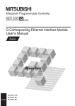
Ethernet cable connection
This section describes how to connect the built-in Ethernet to a 100BASE-TX/10BASE-T network.
<Connection procedure>
1.
2.
Connect the Ethernet cable to a hub.
Connect the Ethernet cable to the built-in Ethernet.
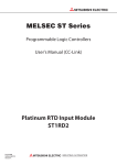
The following shows the Ethernet cable connection diagram.
RJ45 type modular jack
RJ45 type modular
Ethernet cable (category 3,5 or higher)
• When connected to a hub, the CPU module determines the cable used (100BASE-TX or 10BASE-T) and
the communication mode (full-duplex or half-duplex) according to the hub (Auto-negotiation function). Set
the hub to the half-duplex mode if the hub that does not support the auto-negotiation function.
• When the ground terminal of the CPU module cannot be grounded, the communication line may be closed
due to the effects of noise, making it impossible to communicate with other devices.
2 SPECIFICATIONS
2.2 Connection specifications
11
3
LIST OF FUNCTIONS
The following table shows the list of functions of the built-in Ethernet of the CPU module.
12
Function
Outline of system
Reference
Direct connection with
MELSOFT
Built-in Ethernet of CPU module and MELSOFT product (GX Works3, etc.) are
connected by single Ethernet cable without using a hub. Communication is done by
simply specifying the connection destination; you don't have to set the IP address.
Page 14 Direct Connection with
Engineering Tool
MELSOFT connection
Communication with MELSOFT products (GX Works3, etc.) is done within LAN such as
company internal LAN.
Page 17 Connection via a hub
Connected CPU search
function
Searches for built-in Ethernet (CPU module) connected with personal computer using
GX Works3 within the same hub. Acquires IP address by selecting from search results
list.
Page 20 Searching CPU Modules
on Network
MELSOFT diagnosis function
Diagnoses built-in Ethernet of CPU module from GX Works3. (Ethernet diagnostics)
Page 106 Ethernet diagnostics
SLMP communication function
Reads and writes PLC data from other device.
Page 25 SLMP FUNCTION
Predefined protocol support
function
When the predefined protocol support function is used, data can be exchanged with the
external device.
Page 37 PREDEFINED
PROTOCOL SUPPORT
FUNCTION
Socket communication function
By using socket communication instructions, any data can be transferred from and to
the external devices connected through Ethernet using TCP or UDP.
Page 62 SOCKET
COMMUNICATION FUNCTION
Remote password
Remote password setting can prevent unauthorized access from the outside and
enhance the security of the system.
Page 94 REMOTE PASSWORD
IP address change function
This function is provided to change the IP address of the CPU module by setting the
desired IP address to special registers from a peripheral unit or another unit and turning
ON a special relay.
Page 99 IP ADDRESS CHANGE
FUNCTION
3 LIST OF FUNCTIONS
MEMO
3
3 LIST OF FUNCTIONS
13
4
CONNECTION WITH MELSOFT PRODUCT AND
GOT
This chapter describes the method of communication between the CPU module and MELSOFT Product (engineering tool, MX
Component, etc.) or GOT.
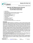
4.1
Direct Connection with Engineering Tool
The CPU module can be directly connected to the engineering tool (GX Works3) with an Ethernet cable, without using a hub.
For direct connection, the IP address and host name need not be specified. (Communication using simultaneous broadcast)
CPU module
Ethernet cable
Engineering tool
An Ethernet cable used for direct connection will be longer compared with the USB cable. This can cause an
unauthorized connection from a remote location.
With GX Works3, you can prevent hacking by opting to “Disable Direct Connection with MELSOFT” by
Navigation window[Parameter][FX5UCPU][Module Parameter][Ethernet Port][Application
Settings] [Security].
14
4 CONNECTION WITH MELSOFT PRODUCT AND GOT
4.1 Direct Connection with Engineering Tool
Setting method
In case of GX Works3, this is done using the "Specify Connection Destination Connection" screen.
Online[Specify Connection Destination]
1.
4
2.
3.
4.
1.
2.
Select "Ethernet Board" for "PC side I/F".
Select "PLC Module" for "PLC side I/F".
In the "PLC side I/F Detailed Setting of PLC Module" screen, select the "Ethernet Port Direct Connection" as shown below.
3.
Set "Other Station Setting".
Select an item appropriate to the operating environment.
4.
Set the Ethernet adapter of the personal computer.
Select an item appropriate to the operating environment.
4 CONNECTION WITH MELSOFT PRODUCT AND GOT
4.1 Direct Connection with Engineering Tool
15
Precautions
Connection to LAN line
When connecting the CPU module to a LAN line, do not set direct connection. Doing so will apply a load on the LAN line and
adversely affect communications with other external devices.
Indirect connection
• Do not set up direct connection when a CPU module is connected to an external device in a one-to-one basis using a hub
as shown below.
CPU module
Hub
Ethernet cable
Engineering tool
• When two or more Ethernet ports are enabled in the network connections setting on the personal computer, communication
by direct connection is not possible. In the PC setting, leave only one Ethernet port enabled for direct connection and
disable other Ethernet ports.
Conditions that disallow direct connection
When the following condition is met, it may not be possible to communicate directly. In such case, check the setting of the
CPU module and/or personal computer.
• In the CPU module IP address bits, if the bits corresponding to "0" in the personal computer subnet mask are all ON or all
OFF.
Ex.
CPU module IP address: 64. 64. 255. 255
Personal computer IP address: 64. 64. 1. 1
Personal computer subnet mask: 255. 255. 0. 0
• In the CPU module IP address bits, if the bits corresponding to the host address of the class of the personal computer IP
address are all ON or all OFF.
Ex.
Personal computer IP address: 192. 168. 0. 1 192.x.x.x., class C and the host address is the fourth octet.
Personal computer subnet mask: 255. 0. 0. 0
CPU module IP address: 64. 64. 255. 255 each bit turns on because of the fourth octet is 255
The IP address for each class is as follows.
• Class A: 0.x.x.x to 127.x.x.x
• Class B: 128.x.x.x to 191.x.x.x
• Class C: 192.x.x.x to 223.x.x.x
The host address for each class is the portion including "0" as shown below.
• Class A: 255. 0. 0. 0
• Class B: 255.255. 0. 0
• Class C: 255.255.255. 0
16
4 CONNECTION WITH MELSOFT PRODUCT AND GOT
4.1 Direct Connection with Engineering Tool
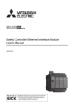
4.2
Connection via a hub
In case of connection to Ethernet via hub, you must do CPU module settings and MELSOFT Product (engineering tool, etc.)
settings or GOT settings.
CPU module
CPU module
Ethernet
Hub
4
Engineering tool Engineering tool
GOT
The flow up to start of Ethernet communication by the connection via a hub is as follows.
1.
Setting parameters
Create unit parameters with the engineering tool. (Page 18 Setting module parameters)
2.
Writing to the CPU module
Turn power OFF ON or reset the system to enable the parameters. (Page 18 Writing to the CPU module)
3.
Connecting cables and external devices
Connect for Ethernet communication. (Page 11 Connection specifications)
4.
Setting the connection destination
Set connection destination with the engineering tool. (Page 19 Engineering Tool Settings)
For GOT settings, refer to the following manuals.
GOT2000 Series Connection Manual (MELSEC iQ-F Series Connection)
GOT1000 Series Connection Manual (MELSEC iQ-F Series Connection)
4 CONNECTION WITH MELSOFT PRODUCT AND GOT
4.2 Connection via a hub
17
Setting the CPU Module
Setting module parameters
In case of GX Works3, this is done using the "Module parameter" settings screen.
Navigation window[Parameter][FX5UCPU][Module Parameter][Ethernet Port][Basic Settings][Own Node
Settings]
1.
2.
Set IP address of the CPU module.
Set MELSOFT connections.
Navigation window[Parameter][FX5UCPU][Module Parameter][Ethernet Port][Basic Settings][External
Device Configuration][Detailed Setting][Ethernet Configuration (Built-in Ethernet Port)] screen
• Drag and drop "MELSOFT Connection Module" from the "Module List" to the left side of the screen.
Writing to the CPU module
Write the parameters set in the CPU module.
[Online][Write to PLC]
After writing the parameters to the CPU module, power off and on or reset the CPU module to enable the parameters.
18
4 CONNECTION WITH MELSOFT PRODUCT AND GOT
4.2 Connection via a hub
Engineering Tool Settings
In case of GX Works3, this is done using the "Specify Connection Destination Connection" screen.
Online[Specify Connection Destination]
1.
4
2.
3.
1.
2.
Select "Ethernet Board" for "PC side I/F".
Select "PLC Module" for "PLC side I/F".
Input the CPU IP address or host name in the "PLC side I/F Detailed Setting of PLC Module" screen as shown in the following
figure.
In case of host name, set the name specified in the Microsoft Windows hosts file.
3.
Set "Other Station Setting".
Select an item appropriate to the operating environment.
4 CONNECTION WITH MELSOFT PRODUCT AND GOT
4.2 Connection via a hub
19
Searching CPU Modules on Network
In the case of GX Works3, with connections using the hub, you can search for and display of list of CPU modules connected
to the same hub as personal computer (GX Works3) by clicking "Find" button from the "PLC side I/F Detailed Setting of PLC
Module" screen.
• CPU modules connected to cascaded hubs are also searched and a list of them is displayed.
• CPU modules connected via router cannot be searched.
• Some CPU modules connected via wireless LAN may not be found since Ethernet communication may not be stable due to
packet loss.
• If multiple CPU modules with the same IP address are found in the list, check the IP address parameters for the CPU
modules. Starting communication with the IP address duplicated will cause a communication error.
• Appropriate CPU modules may not be found if the service processing load is heavy. In such case, increase the response
waiting time value in the "Search for the FX5CPU on network" screen, or change the service processing counts in the
service processing settings of the CPU parameters.
20
4 CONNECTION WITH MELSOFT PRODUCT AND GOT
4.2 Connection via a hub
• By selecting "Do Not Respond" in "Do Not Respond to CPU Module Search" in "Application Settings" on "Module
Parameter Ethernet Port" screen, the CPU module search function can be disabled, making the system not respond to
search request on the network.
4
4 CONNECTION WITH MELSOFT PRODUCT AND GOT
4.2 Connection via a hub
21
Communication via Router
Access via routers from built-in Ethernet port is available in an environment such as a corporate LAN. *1
Router
Corporate
LAN
Factory
CPU module
*1
Control room
Personal
computer
Communication through routers is impossible for some functions. The following functions do not support communication via routers.
• Searching for CPU Modules on the network
• Simultaneous broadcast of socket communication function
For access via router, set the subnet mask pattern and default gateway IP address in addition to IP address as per Page
18 Setting module parameters.
In the case of GX Works3:
Navigation window[Parameter][FX5UCPU][Module Parameter][Ethernet Port][Basic Settings][Own Node
Settings]
22
4 CONNECTION WITH MELSOFT PRODUCT AND GOT
4.2 Connection via a hub
Precautions
IP address duplication
Check that the IP address is not duplicated when configuring a network or connecting a new device to a network.
If the IP address is duplicated, a device may communicate with the wrong device.
Check for IP address duplication in the following way.
• Check for IP address duplication with the Search connected CPU function.
KeepAlive check
When the protocol is set to TCP, KeepAlive check is performed. (Checking for a response to a KeepAlive ACK message)
4
An alive check message is sent five seconds after reception of the last message from the connected device to check if the
device returns a response or not. If no response is received, the alive check message will be resent at intervals of five
seconds. When no response is received for 45 seconds, the connected device is regarded as non-existent and the connection
is disconnected.
If the connected device does not support the TCP KeepAlive function, the connection may be disconnected.
Connections exceeding the setting
Do not exceed the number of connections set in the Ethernet configuration settings of the parameters. If the personal
computer makes a number of TCP connections that exceeds the set number, the following state results depending on the
application.
• Timeout error detection time gets extended.
• Unexpected timeout error occurs in any of the communicating devices.
Retransmission in case of TCP connection
If no ACK response is returned from the other end of a TCP connection, the ACK will be resent six times, starting in 0.3
seconds after the first transmission, and then 0.6, 1.2, 2.4, 4.8, and 9.6 seconds. When no TCP ACK response is returned
within 19.2 seconds after the last retransmission, the device is regarded as faulty and the connection is disconnected. (As a
result, the connection is disconnected in total of 38.1 seconds.)
4 CONNECTION WITH MELSOFT PRODUCT AND GOT
4.2 Connection via a hub
23
TCP MELSOFT connection
In case of TCP communication with multiple MELSOFT devices (GX Works3, etc.), set the same number of MELSOFT
devices in the unit parameters.
CPU module
Ethernet
Hub
MELSOFT device
MELSOFT device
MELSOFT device
Set the same number
of devices as
MELSOFT devices
When all MELSOFT devices start communicating at the same time, devices may fail to communicate because
of the congestion in communication. In such a case, schedule the timing for when each device starts
communicating so that the communication congestion will not occur. When using GOTs, for example, set
different rise time and time-out values in the GOTs.
Sampling trace
When sampling trace is executed using the engineering tool from the built-in Ethernet port, abort the connection before
turning OFF the power of the CPU module.
Remote STOP
When remote STOP is executed using the engineering tool from the built-in Ethernet port, execute remote RUN before turning
OFF the power of the CPU module.
24
4 CONNECTION WITH MELSOFT PRODUCT AND GOT
4.2 Connection via a hub
5
SLMP FUNCTION
SLMP (Seamless Message Protocol) is a protocol for accessing SLMP-compatible devices from an external device (such as
personal computer or GOT) using TCP or UDP through Ethernet.
For the FX5 built-in Ethernet port, communication is possible by SLMP 3E frames.
CPU module device data can be read and written using SLMP (3E frames) from external devices.
CPU module operation monitoring, data analysis, and production control is possible from external devices by reading and
writing device data.
With the remote password function, unauthorized access from the outside can be prevented. (Page 94 REMOTE
PASSWORD)
For details on the SLMP function, refer to the MELSEC iQ-F FX5 User's Manual (SLMP).
CPU module
5
Hub
GOT
SLMP communication
SLMP 3E frames have the same message format as that of the MC protocol QnA-compatible 3E frames.
External devices that have been used with the MC protocol can be connected to SLMP-compatible devices as
they are.
The following shows the flow until starting communication by SLMP (3E frames).
1.
Connecting cables and external devices
Make the connections for SLMP communication. (Page 11 Connection specifications)
2.
Setting parameters
Configure the module parameters with the engineering tool. (Page 28 Setting Method)
3.
Writing to the CPU module
Write the parameters set in the CPU module. Turn power OFF ON or perform system reset to enable the parameters.
Access through routers is also available. In order to configure this, set the subnet mask pattern and default
gateway IP address. (Page 22 Communication via Router)
5 SLMP FUNCTION
25
5.1
Specifications
Communication specifications
Communication by the SLMP function is implemented with the following specifications, and they can be configured in module
parameters in the GX Works3.
Item
Transmission
specifications
Specification
Data transfer speed
100/10 Mbps
Communication mode
Full-duplex or half-duplex
Interface
RJ45 connector
Transmission method
Base band
Maximum segment length (Maximum
distance between hub and node)
100 m
Number of cascade
connections
100BASE-TX
2 levels maximum*1
10BASE-T
4 levels maximum*1
Number of ports
1 port
Number of connections
8 connections maximum*2
*1
*2
This number applies when a repeater hub is used. When using a switching hub, check the number of cascaded stages with the
manufacturer of the hub to be used.
Maximum of 8 connections including SLMP, MELSOFT connections, socket communication, and predefined protocol support.
Hubs with 100BASE-TX or 10BASE-T ports can be connected.
A personal computer can also be directly connected without using a hub.
The ports must comply with the IEEE802.3 100BASE-TX or IEEE802.3 10BASE-T standards.
26
5 SLMP FUNCTION
5.1 Specifications
Link specifications
For applicable commands and devices, refer to Page 29 SLMP Commands.
Link time
■3E frames
Calculate the minimum processing time for transmission by SLMP with the following formula.
However, the processing time may further increase due to the network load (line congestion), window size of connected
devices, the number of simultaneously used connections, and the system configuration. Use the result of this formula as a
guideline value of the processing time, when only 1 connection is being used.
• Minimum processing time for communication by SLMP (for batch read, batch write)
Tfs=Ke+(KdtDf)+Scrnumber of scans required for processing+other device ACK processing time
Tfs: The time from when the personal computer receives the request data until the PLC finishes processing (unit: ms)*1
Ke, Kdt: Constants (refer to the table below)
5
Df: Number of words of requested data+Number of words of response data (application data portion)
Scr: Scan time
*1
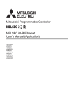
The following shows the timing from when the personal computer receives the request data until the PLC finishes processing.
Target device
(personal computer)
Command message
0 step
Response message
ACK
(Only TCP)
END
ACK
(Only TCP)
0 step
END
PLC scan
time
Tfs
Communication content
Batch read
Batch writing
When communicating as ASCII code data
For TCP/IP communication
For UDP/IP communication
Ke
Kdt
Ke
Kdt
1
0.001
1
0.001
When communicating as binary code data
1
0.001
1
0.001
When communicating as ASCII code data
1
0.001
1
0.001
When communicating as binary code data
1
0.001
1
0.001
Ex.
[Calculation example 1]
When performing TCP/IP communication with a personal computer and reading 32 points (devices) of data from the own
station's data register (D) as binary code data, using SLMP communication, the time from when the computer request data is
received until processing is finished (unit: ms)
Connected station scan time is 40 ms.
Tfs=1+(0.00132)+401+other device ACK processing time
[Calculation example 2]
When performing TCP/IP communication with a personal computer and writing 32 points (devices) of data to the own station's
data register (D) as binary code data, using SLMP communication, the time from when the computer request data is received
until processing is finished (unit: ms)
Connected station scan time is 40 ms.
Tfs=1+(0.00132)+401+other device ACK processing time
5 SLMP FUNCTION
5.1 Specifications
27
5.2
Setting Method
The following shows the configuration for communication by SLMP.
Navigation window[Parameter][FX5UCPU][Module Parameter][Ethernet Port][Basic Settings][Own Node
Settings]
1.
2.
Under "Own Node Settings", configure "IP Address" setting.
Configure the connection for the SLMP connection.
Navigation window[Parameter][FX5UCPU][Module Parameter][Ethernet Port][Basic Settings][External
Device Configuration][Detailed Setting][Ethernet Configuration (Built-in Ethernet Port)] screen
3.
Drag and drop "SLMP Connection Module" under "Module List" to the left side of the screen. Select protocol (TCP or
UDP) that matches the other device in "Protocol". Set the own station port number (setting range: 1025 to 4999, 5010 to
65534) for the "Port No.". Do not specify 5000 to 5009 because these ports are used by the system.
When writing during RUN is not allowed, if the CPU module receives a request to write data from the external
device, it returns a NAK message without writing the data.
28
5 SLMP FUNCTION
5.2 Setting Method
5.3
SLMP Commands
For details on the SLMP commands, refer to the MELSEC iQ-F FX5 User's Manual (SLMP).
Command list
The following commands can be executed with the SLMP function.
3E frames
Name
Command
Subcommands
Processing content
Number of points
processed per
communication
Device Read
(Batch)
0401H
0001H
This command reads data from a bit device or word device in units of
1 bit.
ASCII: 1792 points
BIN: 3584 points
Device Write
(Batch)
Device Read
Random
1401H
0403H
0000H
• This command reads data from bit devices in units of 16 bits.
• This command reads data from word devices in units of 1 word.
ASCII: 480 words (7680 points)
BIN: 960 words (15360 points)
0081H
• This command reads data from link direct devices in units of 1 bit.
• This command reads data from the buffer memory in intelligent
function modules in units of 1 bit.
• This command reads data from devices indirectly specified by
index registers in units of 1 bit.
ASCII: 1792 points
BIN: 3584 points
0080H
• This command reads data from link direct devices in units of 1
word.
• This command reads data from the buffer memory in intelligent
function modules in units of 1 word.
• This command reads data from devices indirectly specified by
index registers in units of 1 word.
ASCII: 480 words (7680 points)
BIN: 960 words (15360 points)
0083H
• This command reads data from link direct devices in units of 1 bit.
• This command reads data from the buffer memory in intelligent
function modules in units of 1 bit.
• This command reads data from devices indirectly specified by
index registers in units of 1 bit.
ASCII: 1792 points
BIN: 3584 points
0082H
• This command reads data from link direct devices in units of 1
word.
• This command reads data from the buffer memory in intelligent
function modules in units of 1 word.
• This command reads data from devices indirectly specified by
index registers in units of 1 word.
ASCII: 480 words (7680 points)
BIN: 960 words (15360 points)
0001H
This command writes data to bit devices in units of 1 bit.
5
ASCII: 1792 points
BIN: 3584 points
0000H
• This command writes data to bit devices in units of 16 bits.
• This command writes data to word devices in units of 1 word.
ASCII: 480 words (7680 points)
BIN: 960 words (15360 points)
0081H
• This command writes data to the buffer memory in intelligent
function modules and SLMP-compatible devices in units of 1 bit.
• Bit devices, word devices, and buffer memory are indirectly
specified by index registers.
ASCII: 1792 points
BIN: 3584 points
0080H
This command writes data to the buffer memory in intelligent function
modules and SLMP-compatible devices in units of 1 word (16 bits).
ASCII: 480 words (7680 points)
BIN: 960 words (15360 points)
0083H
This command writes data to the buffer memory in intelligent function
modules and SLMP-compatible devices in units of 1 bit.
ASCII: 1972 points
BIN: 3584 points
0082H
This command writes data to the buffer memory in intelligent function
modules and SLMP-compatible devices in units of 1 word (16 bits).
ASCII: 480 words (7680 points)
BIN: 960 words (15360 points)
0000H
This command reads data from word devices in units of 1 word or 2
words by randomly specifying device numbers.
ASCII:
(Word access points + double
word access points) 2 192
BIN:
Word access points + double
word access points 192
5 SLMP FUNCTION
5.3 SLMP Commands
29
Name
Command
Subcommands
Processing content
Number of points
processed per
communication
Device Read
Random
0403H
0080H
This command reads data from the buffer memory in intelligent
function modules and SLMP-compatible devices in units of 1 word
(16 bits).
ASCII:
(Word access points + double
word access points) 4 192
BIN:
Word access points + double
word access points 192
0082H
This command reads data from the buffer memory in intelligent
function modules and SLMP-compatible devices in units of 1 word
(16 bits).
ASCII:
(Word access points + double
word access points) 4 192
BIN:
Word access points + double
word access points 192
0001H
This command writes data to bit devices in units of 1 bit by randomly
specifying device numbers.
ASCII: 94 points
BIN: 188 points
0000H
• This command writes data to bit devices in units of 16 bits by
randomly specifying device numbers.
• This command writes data to word devices in units of 1 word or 2
words by randomly specifying device numbers.
ASCII:
((Word access points) 12+
(double-word access points)
14) 2 1920
BIN:
(Word access points) 12+
(double-word access points)
14 1920
0081H
• This command writes data to the buffer memory in intelligent
function modules and SLMP-compatible devices in units of 1 bit.
• Buffer memory is indirectly specified by index registers.
ASCII: 47 points
BIN: 94 points
0080H
This command writes data to the buffer memory in intelligent function
modules and SLMP-compatible devices in units of 1 word (16 bits) or
2 words.
ASCII:
((Word access points) 12+
(double-word access points)
14) 4 1920
BIN:
((Word access points) 12+
(double-word access points)
14) 2 1920
0083H
This command writes data to the buffer memory in intelligent function
modules and SLMP-compatible devices in units of 1 bit.
ASCII: 47 points
BIN: 94 points
0082H
This command writes data to the buffer memory in intelligent function
modules and SLMP-compatible devices in units of 1 word (16 bits) or
2 words.
ASCII:
((Word access points) 12+
(double-word access points)
14) 4 1920
BIN:
((Word access points) 12+
(double-word access points)
14) 2 1920
0000H
With n points of bit devices and word devices as 1 block, this
command reads data by randomly specifying multiple blocks.
(When bit devices are specified, 1 point is 16 bits.)
ASCII:
(Number of word device blocks
+ number of bit device blocks)
2 120 and (Total points of
each blocks of word device +
total points of each blocks of bit
device) 2 960
BIN:
Number of word device blocks
+ number of bit device blocks
120 and Total points of each
blocks of word device + total
points of each blocks of bit
device 960
Device Write
Random
Device Write
Random
Device Read Block
30
1402H
1402H
0406H
5 SLMP FUNCTION
5.3 SLMP Commands
Name
Command
Subcommands
Processing content
Number of points
processed per
communication
Device Read Block
0406H
0080H
With n points of buffer memory in intelligent function modules and
SLMP-compatible devices as 1 block, this command reads data by
randomly specifying multiple blocks.
(When bit devices are specified, 1 point is 16 bits.)
ASCII:
(Number of word device blocks
+ number of bit device blocks)
4 120 and (Total points of
each blocks of word device +
total points of each blocks of bit
device) 2 960
BIN:
(Number of word device blocks
+ number of bit device blocks)
2 120 and Total points of
each blocks of word device +
total points of each blocks of bit
device 960
0082H
With n points of buffer memory in intelligent function modules and
SLMP-compatible devices as 1 block, this command reads data by
randomly specifying multiple blocks.
ASCII:
(Number of word device blocks
+ number of bit device blocks)
4 120 and (Total points of
each blocks of word device +
total points of each blocks of bit
device) 2 960
BIN:
(Number of word device blocks
+ number of bit device blocks)
2 120 and Total points of
each blocks of word device +
total points of each blocks of bit
device 960
0000H
With n points of bit devices and word devices as 1 block, this
command writes data by randomly specifying multiple blocks.
(When bit devices are specified, 1 point is 16 bits.)
ASCII:
(Number of word device blocks
+ number of bit device blocks)
2 120 and ((Number of
word device blocks + number
of bit device blocks) 4 + Total
points of each blocks of word
device + total points of each
blocks of bit device) 2 770
BIN:
Number of word device blocks
+ number of bit device blocks
120 and (Number of word
device blocks + number of bit
device blocks) 4 + Total
points of each blocks of word
device + total points of each
blocks of bit device 770
0080H
With n points of buffer memory in intelligent function modules and
SLMP-compatible devices as 1 block, this command writes data by
randomly specifying multiple blocks.
(When bit devices are specified, 1 point is 16 bits.)
ASCII:
(Number of word device blocks
+ number of bit device blocks)
4 120 and ((Number of
word device blocks + number
of bit device blocks) 4 + Total
points of each blocks of word
device + total points of each
blocks of bit device) 2 770
BIN:
(Number of word device blocks
+ number of bit device blocks)
2 120 and (Number of word
device blocks + number of bit
device blocks) 4 + Total
points of each blocks of word
device + total points of each
blocks of bit device 770
Device Write Block
1406H
5 SLMP FUNCTION
5.3 SLMP Commands
5
31
32
Name
Command
Subcommands
Processing content
Number of points
processed per
communication
Device Write Block
1406H
0082H
With n points of buffer memory in intelligent function modules and
SLMP-compatible devices as 1 block, this command writes data by
randomly specifying multiple blocks.
ASCII:
(Number of word device blocks
+ number of bit device blocks)
4 120 and ((Number of
word device blocks + number
of bit device blocks) 4 + Total
points of each blocks of word
device + total points of each
blocks of bit device) 2 770
BIN:
(Number of word device blocks
+ number of bit device blocks)
2 120 and (Number of word
device blocks + number of bit
device blocks) 4 + Total
points of each blocks of word
device + total points of each
blocks of bit device 770
Remote Run
1001H
0000H
This command performs a remote RUN request for a device.
Remote Stop
1002H
0000H
This command performs a remote STOP request for a device.
Remote Pause
1003H
0000H
This command performs a remote PAUSE request for a device.
Remote Latch
Clear
1005H
0000H
This command performs a remote latch clear request when the
device is in the STOP state.
Remote Reset
1006H
0000H
This command performs a remote reset request to reset the device
error stop state.
Read Type Name
0101H
0000H
This command reads the processor module name code (processor
type) of a device.
Global
1618H
0000H
Turns off the global signal.
0001H
Turns on the global signal.
Self-Test
0619H
0000H
This command checks if normal communication is possible.
Clear Error
1617H
0001H
This command batch clears all errors and turns off the LED.
Password Lock
1631H
0000H
This command sets to the locked status from the unlocked status by
specifying the remote password. (Sets the device to the state where
communication is not possible.)
Password Unlock
1630H
0000H
This command sets to the unlocked status from the locked status by
specifying the remote password. (Sets the device to the state where
communication is possible.)
5 SLMP FUNCTION
5.3 SLMP Commands
Applicable devices
The following shows the available devices and device number ranges in commands used for the SLMP communication
function.
3E frames
With 3E frames, specify the device to access with the "Device code" listed below.
Classification
Device
Type
Internal user
device
Input
Bit
Device code*1
(Device specification format:
Long)
ASCII code
Binary code
X*
(X***)
9CH
(9C00H)
Output
Y*
(Y***)
9DH
(9D00H)
Internal relay
M*
(M***)
Latching relay
Device No.
Applicable
FX5 CPU
device*2
Octal
Octal
90H
(9000H)
Decimal
L*
(L***)
92H
(9200H)
Decimal
Annunciator
F*
(F***)
93H
(9300H)
Decimal
Edge relay
V*
(V***)
94H
(9400H)
Decimal
Link relay
B*
(B***)
A0H
(A000H)
Hexade
cimal
Step relay
S*
(S***)
98H
(9800H)
Decimal
D*
(D***)
A8H
(A800H)
Decimal
W*
(W***)
B4H
(B400H)
Specify in the range of
device numbers of the
module to access.
Hexade
cimal
Decimal
Data register
Word
Link register
Timer
Long timer
Retentive timer
Long retentive
timer
Counter
Specify in the range of
device numbers of the
module to access.
Contact
Bit
TS
(TS**)
C1H
(C100H)
Coil
Bit
TC
(TC**)
C0H
(C000H)
Current value
Word
TN
(TN**)
C2H
(C200H)
Contact
Bit
(LTS*)
51H
(5100H)
Coil
Bit
(LTC*)
50H
(5000H)
Current value
Double
Word
(LTN*)
52H
(5200H)
Contact
Bit
SS
(STS*)
C7H
(C700H)
Coil
Bit
SC
(STC*)
C6H
(C600H)
Current value
Word
SN
(STN*)
C8H
(C800H)
Contact
Bit
(LSTS)
59H
(5900H)
Coil
Bit
(LSTC)
58H
(5800H)
Current value
Double
Word
(LSTN)
5AH
(5A00H)
Contact
Bit
CS
(CS**)
C4H
(C400H)
Coil
Bit
CC
(CC**)
C3H
(C300H)
Decimal
Decimal
Decimal
Decimal
5
5 SLMP FUNCTION
5.3 SLMP Commands
33
Device
ASCII code
Binary code
Internal user
device
Counter
Current value
Word
CN
(CN**)
C5H
(C500H)
Long counter
Contact
Bit
(LCS*)
55H
(5500H)
Coil
Bit
(LCC*)
54H
(5400H)
Current value
Double
Word
(LCN*)
56H
(5600H)
Link special relay
Bit
SB
(SB**)
A1H
(A100H)
Hexade
cimal
Link special register
Word
SW
(SW**)
B5H
(B500H)
Hexade
cimal
Special relay
Bit
SM
(SM**)
91H
(9100H)
Hexade
cimal
Special register
Word
SD
(SD**)
A9H
(A900H)
Hexade
cimal
Function input
Bit
Hexade
cimal
Hexade
cimal
Decimal
Decimal
Decimal
System device
Type
Function output
*2
*3
Decimal
Z*
(Z***)
CCH
(CC00H)
32 bits
LZ
(LZ***)
62H
(6200H)
Word
R*
(R***)
AFH
(AF00H)
Decimal
ZR
(ZR**)
B0H
(B000H)
Decimal
X*
(X***)
9CH
(9C00H)
Hexade
cimal
Link output
Y*
(Y***)
9DH
(9D00H)
Hexade
cimal
Link relay
B*
(B***)
A0H
(A000H)
Hexade
cimal
Link special relay
SB
(SB**)
A1H
(A100H)
Hexade
cimal
W*
(W***)
B4H
(B400H)
Hexade
cimal
S*
(S***)
B5H
(B500H)
Hexade
cimal
W*
(W***)
B4H
(B400H)
Hexade
cimal
Link special register
S*
(S***)
B5H
(B500H)
Hexade
cimal
Module access device
G*
(G***)
ABH
(AB00H)
Decimal
Link input
Bit
Word
Link special register
*1
Decimal
Link register
Module access
device*3
Specify in the range of
device numbers of the
module to access.
Applicable
FX5 CPU
device*2
Word
File register
Link direct
device*3
Device No.
16 bits
Function register
Index register
34
Device code*1
(Device specification format:
Long)
Classification
Link register
Word
Specify in the range of
device numbers of the
module to access.
[ASCII code]
If the device code is less than the specified character number, add "*" (ASCII code: 2AH) or a space (ASCII code: 20H) after the device
code.
[Binary code]
When "Device code" is less than the size specified add "00H" to the end of the device code.
: An FX5 CPU device exists
: No FX5 CPU device
"Device memory extension specification" for sub-commands must be turned ON (1).
5 SLMP FUNCTION
5.3 SLMP Commands
5.4
Precautions
Checking communication status based on LED display
Check the status of the "SD/RD" LED display on the CPU module's built-in Ethernet port.
"SD/RD" LED indicator
status
Operation status
Flashing
Data is being sent or received.
Off
Data is not being sent nor received.
The LED flashes brightly when performing SLMP (3E frame) communication normally.
If the LED is not flashing, check the wiring and the communication settings.
Checking communication status based on error code
5
For the error codes stored in the end code when there is an abnormal end of SLMP (3E frame) communication, refer to
Page 113 SLMP function error code.
Number of connectable units
Up to 8 external devices can access one CPU module at the same time (including socket communication, MELSOFT
connections, and SLMP).
Connection of user application
and other device(SLMP)
MELSOFT connection
Target
device (Client)
FX5 CPU
Maintenance
GX Works3, etc. (MELSOFT connection)
For connections with external devices by SLMP, the number of possible simultaneous connections is the number of devices
configured in the Ethernet configuration settings only.
Data communication frames
The frames that can be used on the CPU module are the same as MC protocol QnA-compatible 3E frames.
Access range
• Only the connected CPU module can be accessed. Transmissions to other modules will result in an error.
• Communication with other stations such as CC-Link via the connected CPU module cannot be done.
For details of the access range, refer to the MELSEC iQ-F FX5 User's Manual (SLMP).
5 SLMP FUNCTION
5.4 Precautions
35
Precautions when the protocol is set to UDP
• For a single UDP port, if a new request message is sent while waiting for the response message after sending the first
request message, the new request message will be discarded.
• When the same local port number has been set multiple times in UDP, the result is the same as if only one has been set. If
you want to communicate with multiple external devices using the same local port number, use TCP.
Data reception processing for response messages
The following shows an example of the data reception processing of an external device.
Communication process of the
target device
Send request message
Receive response message
NO
Is TCP connection open?
YES
NO
Could data be received
within the monitor timer
value?
YES
Check the received data size
NO
Is receive data-size
sufficient?
YES
Process the response message
Was the entire received
message processed?
NO
YES
End
Error handling
For Ethernet communication, TCP socket functions are used inside personal computers.
These functions have no concept of boundaries. When the sender sends data by calling the send function
once, the receiver will call the recv function once or more to read that data. (Send and recv do not have a oneto-one correspondence.)
Therefore, the processing shown above is always required in the program of the receiving device.
When the recv function is used with the blocking mode, data may be read by calling the function once.
36
5 SLMP FUNCTION
5.4 Precautions
6
PREDEFINED PROTOCOL SUPPORT
FUNCTION
This chapter describes predefined protocol support function (built-in Ethernet).
For details on the predefined protocol support function (serial communication), refer to MELSEC iQ-F FX5 User's Manual
(Serial Communication).
Outline
Data can be exchanged between the external device (such as measuring instrument and bar code reader) and the CPU
module following the protocol of the device.
Data that varies according to communication session can be handled by incorporating a device or buffer memory into the
communication packet.
Sets the protocol required for communication with the external device using the engineering tool.
The protocol can be set by selecting from the predefined protocol library (SLMP, MODBUS/TCP*1, etc.), or it can be created
and edited.
*1
6
The SLMP and MODBUS/TCP are available only in the client.
Setting protocols
Writing protocols
Protocols can be set easily using the predefined
protocol support function of GX Works3.
Write the set protocols in the CPU module.
GX Works3
Sending
CPU module
External device
External device
Receiving
Executing protocols
Execute protocols by dedicated instructions.
Multiple protocols can be executed by one dedicated instruction.
Data can be communicated
with protocols appropriate
to each external device.
The number of protocols and packets that can be registered is as follow.
• Protocols: 64 maximum
• Packets: 128 maximum
• Packet data area size: 6144 bytes maximum
When the number of packets reaches the upper limit, protocols cannot be added even if the number of
protocols has not reached the upper limit.
If the packet data area size reaches the upper limit, protocols and packets cannot be added even if the
number of protocols and packets has not reached the upper limit.
Applicable connections
The connections Nos. 1 to 8 can be used for communications using the communication protocol support function.
6 PREDEFINED PROTOCOL SUPPORT FUNCTION
37
6.1
Data Communication
When the predefined protocol support function is used, data can be exchanged with the external device using the following
procedure.
1.
Select, create or edit the protocol with the predefined protocol support function, and write the protocol setting data.
(Page 38 Creating the protocol setting data)
2.
3.
4.
5.
6.
Set the module parameter. (Page 43 Module parameter setting procedure)
Write the parameters to the CPU module.
Perform the open processing to establish a connection between the CPU module and external device.
Execute the protocol with the dedicated instruction (SP.ECPRTCL instruction).
Close the connection when communication is finished.
The communication data code is binary code communication regardless of the selected settings.
Creating the protocol setting data
Use the predefined protocol support function to create the protocol setting data.
[Tool] [Predefined Protocol Support Function]
Select the module for which to create the protocol setting data.
38
6 PREDEFINED PROTOCOL SUPPORT FUNCTION
6.1 Data Communication
■Newly creating the protocol setting data
Newly create the protocol setting data.
[File] [New] "Protocol Setting" screen
6
Item
Description
Protocol No.
Displays the protocol number used with the dedicated instruction.
Manufacturer
Displays the name of the manufacturer of the device for which the protocol is being set.
Model
Displays the model of the protocol to be set.
Protocol Name
Displays the name of the protocol to be set.
Communication Type
Displays the communication type of the protocol to be set.
Send only: Sends one send packet once.
Receive only: If there is a matching packet within up to 16 registered and received packets, it is received.
Send & receive: After sending one send packet, if there is a matching packet within up to 16 registered and received packets, it
is received.
->Send/<-Receive
Displays the packet send direction.
->: For send
<-(1) to (16): For receive, the received packet number is displayed in parentheses.
Packet Name
Displays the packet name.
Packet Setting
Displays the validity of variables in the packet elements and the variable setting state.
If Variable Unset, Elements Unset, or Element Error, the protocol is not written to the CPU module.
No Variable: When there is no variable in the elements
Variable Set: Only when all variables have been set
Variable Unset: When there is an unset variable
Elements Unset: When there are no elements in an editable protocol
Element Error: When elements do not satisfy requirements
6 PREDEFINED PROTOCOL SUPPORT FUNCTION
6.1 Data Communication
39
■Adding protocol
Add protocol.
[Edit] [Add Protocol]
Item
Description
Type
Select the type of protocol to be added.
Protocol No.
Select the protocol number to be added.
1 to 64
Manufacturer*1
Set the maker of the protocol to be added.
Model*1
Set the type of protocol to be added.
Set the name of the protocol to be added.
Protocol
*1
40
Name*1
The name can be set only when "Predefined Protocol Library" is selected for "Type"
6 PREDEFINED PROTOCOL SUPPORT FUNCTION
6.1 Data Communication
Setting range
• Predefined Protocol Library
• User Protocol Library
• Add New
■Protocol Detailed Setting
Set the protocol send/receive parameters.
"Protocol Setting" window Select a protocol [Edit] [Protocol Detailed Setting]
6
Item
Connected Device
Information*1
Protocol Setting
Information*1
Description
Manufacturer
Set the protocol maker name.
Type
Set the protocol device type.
Model
Set the protocol model.
Version
Set the protocol device version.
Explanation
Set a description of the protocol device.
Protocol No.
The protocol number for the selected protocol is displayed.
Protocol Name
Set the protocol name.
Communication Type
Type Set the protocol communication type.
Receive Setting
Receive Wait Time
Set the time for wait after the module enters the receive data wait state.
If communication with the external device is disabled because of a disconnection and matching packet
data is not received within the specified time, the module judges that an error has occurred and cancels
the receive data wait state.
Send Setting
Standby Time
Set the time to wait from when the protocol set for the module enters the execution state to when the
data is actually sent. The time for the external device to enter the receive enable state can be adjusted
with this in respect to the module's send timing.
*1
The setting cannot be changed if the protocol was selected from the predefined protocol library.
Send/receive parameters can be set for multiple protocols by clicking the [Communication Parameter Batch
Setting] button and setting the range of the set protocol numbers, receive settings, and send settings.
6 PREDEFINED PROTOCOL SUPPORT FUNCTION
6.1 Data Communication
41
■Packet setting
Set the configuration of the send/receive packets on the "Packet Setting" window.
"Protocol Setting" window Packet to be set
The above window opens when "Predefined Protocol Library" is selected on the "Add Protocol" window.
When "Add New" or "User Protocol Library" has been selected, configure the packets with the [Change Type] button and [Add
New] button.
For details on the packet elements, refer to the following.
Page 44 Packet Elements
■Writing the protocol setting data
Write the protocol setting data to the CPU module.
[Online] [Write to Module]
Select the module and memory into which the protocol data is to be written, and execute write.
The protocol setting data is written into the module extension parameters.
42
6 PREDEFINED PROTOCOL SUPPORT FUNCTION
6.1 Data Communication
The following data is not written as the protocol setting data so it will not be displayed even when read.
However, when the protocol is selected from the predefined protocol library, the following can be displayed.
• Manufacturer
• Packet name
• Type, version, and explanation in the protocol detailed setting
• Element name in packet settings
When the predefined protocol settings are written into multiple target memories, the following operation will take place.
When written into both the CPU built-in memory and SD memory card:
Operation follows settings in "Memory Card Parameter".
The predefined protocol settings written in the SD memory card can be transferred to the CPU built-in memory by using boot
operation.
For details on boot operation, refer to the following.
MELSEC iQ-F FX5 User's Manual (Application)
Module parameter setting procedure
Set "External Device Configuration" under "Basic Settings".
6
Page 50 Parameter settings
1.
Select the external device to be connected in "Module List" and drag it to "List of devices" or "Device map area".
External device name
Description
UDP Connection Module
Select to communicate with the external device using UDP/IP
Active Connection Module
Select to perform the open processing to the external device from the CPU module (Active open) and communicate using
TCP/IP.
Unpassive Connection Module
Select to receive the open processing from a unspecified external device (Unpassive open) and communicate using TCP/IP.
Fullpassive Connection Module
Select to receive the open processing from the specified external device (Fullpassive open) and communicate using TCP/IP.
2.
3.
Set "Communication Procedure" for the external device to "Predefined Protocol".
Set the other parameters required for communication in the connection.
Applicable dedicated instructions
The dedicated instruction “SP.ECPRTCL” is used in the communication protocol support function (built-in Ethernet).
6.2
Protocol Communication Type
The packets sent to the external device when a processing is executed and the external device's receive packets are
registered in the protocol.
The packet elements set with the predefined protocol support function are the data section of the packets that are actually
sent and received.
This section describes an example of the packet configuration.
For TCP/IP
Header
Destination
Sender's MAC
MAC address: address:
6 bytes
6 bytes
Ethernet header
Type:
2 bytes
Maximum data length: 2046 bytes
IP:
20 bytes
TCP:
20 bytes
Data
TCP/IP header
6 PREDEFINED PROTOCOL SUPPORT FUNCTION
6.2 Protocol Communication Type
43
For UDP/IP
Header
Destination
Sender's
MAC address: MAC address:
6 bytes
6 bytes
Type:
2 bytes
Maximum data length: 2046 bytes
IP:
20 bytes
Ethernet header
UDP:
8 bytes
Data
UDP/IP header
With the predefined protocol support function, data is exchanged with the external device with the procedures (communication
type) shown below.
Communication type
Description
Send Only
The send packet is sent once.
Receive Only
If there is a packet that matches within the maximum of 16 registered receive packets, the packet is received.
Send & Receive
After sending the send packets, if there are packets that match the up to 16 registered receive packets, the packets are
received.
6.3
Packet Elements
The packet is created with a combination of packet elements.
Up to 32 elements can be set in one packet. One packet can have a maximum data length of 2046 bytes.
This section describes the details of the packet elements.
Static data
Use when there are specific codes and character strings, such as commands, in the packet.
• When sending: The specified code and character string are sent.
• When receiving: The received data is verified.
Multiple static data elements can be placed anywhere in the data part.
The following table lists the items.
44
Item
Description
Remarks
Element Name
Set the element name.
Code Type
Select a data type of the setting value.
ASCII String/ASCII Control Code/HEX
Setting Value
Set data within 1 to 50 bytes.
Code type and setting range are as follows:
• ASCII String: 20H to 7EH
• ASCII Control Code: Control code of 00H to 1FH and 7FH
• HEX: Hexadecimal data of 00H to FFH
Setting example
ASCII String: "ABC"
ASCII Control Code: STX
HEX: FFFF
6 PREDEFINED PROTOCOL SUPPORT FUNCTION
6.3 Packet Elements
Length
The length code is used when there is an element that indicates the data length in the packet.
• When sending: Automatically calculates the data length in the specified range, and adds it to the packet.
• When receiving: From the received data, the data (value) corresponding to the length is verified as the specified range's
data length.
Length elements can be placed anywhere in the data part.
6
Multiple length elements can be set placed in one packet.
The following table lists the items.
Item
Description
Remarks
Element Name
Set the element name.
Code Type
Select the data length type.
ASCII hexadecimal/HEX
Data Length
Select the data length on the line.
The range is 1 to 4 bytes.
Data Flow
Forward Direction
(Upper byte Lower byte)
When sending: Sends the calculated length in order from the upper byte.
When receiving: Receives the data in order from the upper byte.
This cannot be set if the
data length is 1 byte.
Reverse Direction
(Lower byte Upper byte)
When sending: Sends the calculated length in order from the low-order byte.
When receiving: Receives the data in order from the low-order byte.
Byte Swap (by Word)*1
When sending: Interchanges the bytes in word units and sends the
calculated length.
When receiving: Interchanges the bytes in word units and receives the data.
Calculating
Range
*1
Start
Select the start packet element number for the range to be calculated.
The range is 1 to 32.
End
Select the end packet element number for the range to be calculated.
The range is 1 to 32.
This can be selected only when the data length is set to 4 bytes.
• If there are no elements other than length, an element error occurs. (When using length, one or more
elements other than length are required.)
• If the calculation result exceeds the number of digits set with "Data Length", the excessive digit value is
discarded (invalidated). For example, if Data Length is 2 bytes and the data size calculation results are
"123" bytes, the data length will be "23".
• If there is a non-conversion variable (variable length)/non-verified reception (character length variable) after
the length, and that section is not included in the length calculating range, arrange the static data
immediately after the non-conversion variable/non-verified reception.
• When the code type setting is "ASCII Hexadecimal", a mismatch will occur if a character string other than
"0" to "9", "A" to "F", and "a" to "f" is received.
• Use "0" to "9" or "A" to "F" when converting to ASCII characters during send.
• When arranging multiple length elements, none of the length calculating range may overlap.
• When arranging multiple length elements, the previous length calculating range may not exceed the
arranged length.
• A length element cannot be arranged at the final position of the packet elements.
6 PREDEFINED PROTOCOL SUPPORT FUNCTION
6.3 Packet Elements
45
Non-conversion variable
Use this to send the CPU module device data as part of the send packet, or to store part of the received packet in the CPU
module device.
Multiple non-conversion variable can be arranged in one packet.
The following table lists the items.
Item
Description
Element Name
Set the element name.
Fixed Length/
Variable Length
Fixed Length
The data whose length is fixed is sent and received.
Variable Length
When sending: The data length is specified at the time of the protocol execution and the data is sent.
When receiving: The data whose length is variable is received.
Data Length/
Maximum Data
Length
Set the data length of the send/receive data.
(For a variable length, set the maximum data length that can be specified for the data length storage area.)
The range is 1 to 2046.
Unit of Stored Data
Lower byte + Upper byte
When sending: Each one word (2 bytes) data in the data storage area is sent in the order of the lower
byte to the upper byte.
When receiving: The receive data is stored to the data storage area in the order of the lower byte to the
upper byte.
Lower Bytes Only
When sending: Each lower byte data in the data storage area is sent. The CPU module ignores the
upper byte data.
When receiving: The receive data is stored to each lower byte in the data storage area. The CPU
module stores 00H in the upper byte.
Byte Swap
Disable (Lower -> Upper)/
Enable (Upper -> Lower)
When sending: When "Enable (Upper -> Lower)" is selected, data in the upper byte and lower byte are
swapped by one word (2 bytes) and sent. When "Unit of Stored Data" is "Lower Byte + Upper Byte" and
"Data Length" is an odd number of bytes, the upper byte is sent at transmission of the last byte. When
"Unit of Stored Data" is "Lower Bytes Only" and "Data Length" is an odd number of bytes, data without
any byte swap is sent at transmission of the last byte.
When receiving: When "Enable (Upper -> Lower)" is selected, data in the upper byte and lower byte are
swapped by word and sent. When "Unit of Stored Data" is "Lower Byte + Upper Byte" and "Data Length"
is an odd number of bytes, the last byte is stored to the upper byte. When "Unit of Stored Data" is
"Lower Bytes Only" and "Data Length" is an odd number of bytes, the last byte is stored without any
byte swap.
Data Storage Area
Specification
Specify the start device for storing the variable value.
The settable devices are listed below.
User device*1*2
• Input (X)
• Output (Y)
• Internal relay (M)
• Latch relay (L)
• Link relay (B)
• Data register (D)
• Link register (W)
File register*2
• File register (R)
*1
*2
46
Do not set local devices.
Set within the device range specified with "Device/Label Memory Area Setting" in "Memory/Device Setting" under "CPU Parameters".
6 PREDEFINED PROTOCOL SUPPORT FUNCTION
6.3 Packet Elements
The following figures show the configuration of the data storage area.
■When "Fixed Length/Variable Length" is "Fixed Length"
The area after the device number specified on the "Element Setting" window becomes the data storage area.
The occupied data storage area differs according to the "Unit of Stored Data".
• When "Lower Byte + Upper Byte" is selected, the same size as the data length is occupied. (However, when the data length
of a send packet is an odd number, the upper byte (lower byte for "Byte Swap") of the end device is not sent. When the data
length of a receive packet is an odd number, the last data is stored with one byte of 00H.)
• When "Lower Bytes Only" is selected, a size double the data length is occupied.
(Word)
Specified device
+0
Send
packet
Data storage area
Receive
packet
Data storage area
Data storage area
6
+n
For send packet: Send data is stored by the program
For receive packet: Receive data is stored by the CPU module
■When "Fixed Length/Variable Length" is "Variable Length"
The area after the device number specified on the "Element Setting" window + 1 becomes the data storage area.
The occupied data storage area differs according to the "Unit of Stored Data".
• When "Lower Byte + Upper Byte" is selected, the same size as the data length + one word (length for the data length
storage area) are occupied. (However, when the data length of a send packet is an odd number, the upper byte (lower byte
for "Byte Swap") of the end device is not sent. When the data length of a receive packet is an odd number, the last data is
stored with one byte of 00H.)
• When "Lower Bytes Only" is selected, a size double the data length + one word (for data length storage area) is occupied.
(Word)
+0
Specified device
Data length storage area*1
+1
Send
packet
Data storage area
Receive
packet
Data storage area
Data storage area
+n
For send packet: Send data is stored by the program
For receive packet: Receive data is stored by the CPU module
*1
The data length unit is byte fixed
6 PREDEFINED PROTOCOL SUPPORT FUNCTION
6.3 Packet Elements
47
When "Fixed Length/Variable Length" is "Variable Length" and the configuration is set as follows, an error
occurs:
• An element other than static data is placed behind a non-conversion variable element when non-conversion
variable is out of the length calculating range or when there is no length element (except for when
nonconversion variable is placed at the end of the packet elements).
• Multiple non-conversion variable elements are placed in the length calculating range, while a length element
is not placed.
• A non-conversion variable element is placed before a length element in the length calculating range.
Non-verified reception
Use this when receive data include unnecessary data.
If the receive packet contains non-verified reception, CPU module skims over the specified number of characters.
Multiple non-verified reception elements can be set in one packet.
The following table lists the items.
Item
Description
Element Name
Set the element name.
Data Length
0 (Number of characters
variable)
Set when the number of characters that are not verified differs between each communication session.
1 to 2046 (number of
character specification)
Set the number of characters that are not verified.
When "Data Length" is set to 0, an error will occur if the following layout is used.
• An element other than static data is placed behind a non-verified reception element when non-verified
reception is out of the length calculating range or when there is no length element (except for when nonverified reception is placed at the end of the packet elements).
• Multiple non-verified reception elements are placed in the length calculating range, while a length element is
not placed.
• A non-verified reception element is placed before a length element in the length calculating range.
48
6 PREDEFINED PROTOCOL SUPPORT FUNCTION
6.3 Packet Elements
6.4
Execution Conditions of Predefined Protocol
Communications
The predefined protocol communications can be executed when “Predefined protocol ready (SD10692)” is “1”.
This section describes the operation of 'Predefined protocol ready' (SD10692).
When the system is powered on or reset
If protocol setting data is written, the CPU module checks the protocol setting data when the system is powered on or reset.
If the protocol setting data is normal, the CPU module sets “Predefined protocol ready (SD10692)” to “1” and enables
execution of the protocol.
'Predefined protocol ready' (SD10692) is used as the interlock signal for executing the protocol.
If the protocol setting data is abnormal, “Predefined protocol ready (SD10692)” remains “0”, and the details of the error are
stored in SD10710 to SD10713 in the “Predefined protocol setting data check area.
If protocol setting data is not written, the protocol setting data is not checked, and “Predefined protocol ready (SD10692)”
remains “0”.
Whether the protocol setting data is registered or not can be checked with 'Number of registered predefined protocols'
6
(SD10714) and 'Predefined protocol registration' (SD10722 to SD10725).
■When protocol setting data is normal
Power on/reset
Normal result
Checking the protocol
setting data
CPU module
Becomes “1” when the
check result is “normal”.
1
'Predefined protocol ready'
(SD10692)
'Predefined protocol setting
data check area'
(SD10710 to SD10725)
The number of registered protocols and information
about whether protocols have been registered are stored.
■When protocol setting data is abnormal
Power on/reset
Abnormal result
CPU module
Checking the protocol
setting data
Remains “0”.
'Predefined protocol ready'
(SD10692)
'Predefined protocol setting
data check area'
(SD10710 to SD10725)
The error details are stored.
6 PREDEFINED PROTOCOL SUPPORT FUNCTION
6.4 Execution Conditions of Predefined Protocol Communications
49
6.5
Example of Predefined Protocol Communications
This section describes an example of predefined protocol communications using UDP/IP.
System configuration
GX Works3
Sending side
(192.168.3.250)
Receiving side
(192.168.3.251)
Ethernet
Parameter settings
Connect GX Works3 to the CPU module and set the parameters.
■Sending side
1.
Set the CPU module in the following.
[Project] [New]
2.
50
Click the [Yes] button to add the module labels of the CPU module.
6 PREDEFINED PROTOCOL SUPPORT FUNCTION
6.5 Example of Predefined Protocol Communications
3.
Set the "Basic Settings" in the following.
Navigation window[Parameter][FX5UCPU][Module Parameter][Ethernet Port][Basic Settings]
6
4.
Set the external device configuration in the following.
Navigation window[Parameter][FX5UCPU][Module Parameter][Ethernet Port][Basic Settings][External
Device Configuration]
5.
Start the predefined protocol support function.
[Tool] [Predefined Protocol Support Function]
6 PREDEFINED PROTOCOL SUPPORT FUNCTION
6.5 Example of Predefined Protocol Communications
51
6.
Select "CPU(Ethernet)" for "Module Type" and click the [OK] button.
7.
Newly create the protocol setting.
[File] [New]
8.
Set a protocol in the following.
[Edit] [Add Protocol]
52
6 PREDEFINED PROTOCOL SUPPORT FUNCTION
6.5 Example of Predefined Protocol Communications
9.
Set each packet in the following.
"Protocol Setting" window Packet to be set
• Request
6
• Normal response
6 PREDEFINED PROTOCOL SUPPORT FUNCTION
6.5 Example of Predefined Protocol Communications
53
• Error response
10. Write the protocol setting data to the CPU module.
[Online] [Write to Module]
11. Write the set parameters to the CPU module. Then reset the CPU module or power off and on the system.
[Online] [Write to PLC]
54
6 PREDEFINED PROTOCOL SUPPORT FUNCTION
6.5 Example of Predefined Protocol Communications
■Receiving side
1.
Set the CPU module and add the module labels of the CPU module. The setting method of the CPU module and addition
method of the module label are the same as those of when setting the sending side. (Page 50 Sending side)
2.
Set the "Basic Settings" in the following.
Navigation window[Parameter][FX5UCPU][Module Parameter][Ethernet Port][Basic Settings]
6
3.
Set the external device configuration in the following.
Navigation window[Parameter][FX5UCPU][Module Parameter][Ethernet Port][Basic Settings][External
Device Configuration]
4.
Write the set parameters to the CPU module. Then reset the CPU module or power off and on the system.
[Online] [Write to PLC]
6 PREDEFINED PROTOCOL SUPPORT FUNCTION
6.5 Example of Predefined Protocol Communications
55
6.6
Predefined Protocol Support Function Instruction
Executing the registered protocols
SP.ECPRTCL
This instruction executes the communication protocol registered using the engineering tool.
Ladder diagram
Structured text
ENO:=SP_ECPRTCL(EN,U0,s1,s2,s3,d);
(U)
(s1)
(s2)
(s3)
(d)
FBD/LD
EN
ENO
U0
d
s1
s2
s3
("SP_ECPRTCL" enters .)
Setting data
■Descriptions, ranges, and data types
Operand
*1
Description
Range
Data type
Data type (label)
Dummy (Input the character string ['U0'].)
Character string
ANYSTRING_SINGLE
(s1)
Connection number
1 to 8
16-bit unsigned binary
ANY16
(s2)
Number of protocols to be executed continuously
1 to 8
16-bit unsigned binary
ANY16
(s3)
Head device number for storing the control data
Refer to Control data
(Page 57)
Word
ANY16_ARRAY
(Number of elements: 18)
(d)
Head device number which turns ON when the execution of
the instruction is completed and remains on for 1 scan.
If the instruction is completed with an error, (d)+1 is also
turned on.
Bit
ANYBIT_ARRAY
(Number of elements: 2)
(U)
*1
In the case of the ST language and the FBD/LD language, U displays as U0.
■Applicable devices
Operand
Word
Double word
Indirect
specification
Constant
Others
K, H
E
$
X, Y, M, L, SM,
F, B, SB, S
U\G
T, ST,
C, LC
T, ST, C, D,
W, SD, SW, R
U\G
Z
LC
LZ
(U)
(s1)
(s2)
(s3)
(d)
*1
*1
56
Bit
T, ST, C cannot be used.
6 PREDEFINED PROTOCOL SUPPORT FUNCTION
6.6 Predefined Protocol Support Function Instruction
■Control data
Device
Item
Description
Setting range
Set by*1
(s3)+0
Resulting number of
executed protocols
The number of protocols executed by the SP.ECPRTCL instruction is stored.
Any protocol where an error occurred is also included in the execution number. If
the setting of setting data or control data contains an error, "0" is stored.
0, 1 to 8
System
(s3)+1
Completion status
The completion status is stored upon completion of the instruction.
When two or more protocols are executed, the execution result of the protocol
executed last is stored.
• 0: Normal completion
• Other than 0: Error completion (error code)
(s3)+2
Execution protocol
number 1
Specify the number of the protocol to be executed first.
1 to 64
(s3)+3
Execution protocol
number 2
Specify the number of the protocol to be executed second.
0, 1 to 64
(s3)+4
Execution protocol
number 3
Specify the number of the protocol to be executed third.
0, 1 to 64
(s3)+5
Execution protocol
number 4
Specify the number of the protocol to be executed fourth.
0, 1 to 64
(s3)+6
Execution protocol
number 5
Specify the number of the protocol to be executed fifth.
0, 1 to 64
(s3)+7
Execution protocol
number 6
Specify the number of the protocol to be executed sixth.
0, 1 to 64
(s3)+8
Execution protocol
number 7
Specify the number of the protocol to be executed seventh.
0, 1 to 64
(s3)+9
Execution protocol
number 8
Specify the number of the protocol to be executed eighth.
0, 1 to 64
(s3)+10
Collation match
Receive packet
number 1
If receiving is included in the communication type of the protocol that has been
executed first, the receive packet number successful in collation match is stored.
If the communication type is "receive only", "0" is stored. If an error occurs
during execution of the first protocol, "0" is stored.
0, 1 to 16
(s3)+11
Collation match
Receive packet
number 2
If receiving is included in the communication type of the protocol that has been
executed second, the receive packet number successful in collation match is
stored. If the communication type is "receive only", "0" is stored. If an error
occurs during execution of the second protocol, "0" is stored. If the number of
protocols executed is less than 2, "0" is stored.
0, 1 to 16
(s3)+12
Collation match
Receive packet
number 3
If receiving is included in the communication type of the protocol that has been
executed third, the receive packet number successful in collation match is
stored. If the communication type is "receive only", "0" is stored. If an error
occurs during execution of the third protocol, "0" is stored. If the number of
protocols executed is less than 3, "0" is stored.
0, 1 to 16
(s3)+13
Collation match
Receive packet
number 4
If receiving is included in the communication type of the protocol that has been
executed fourth, the receive packet number successful in collation match is
stored. If the communication type is "receive only", "0" is stored. If an error
occurs during execution of the fourth protocol, "0" is stored. If the number of
protocols executed is less than 4, "0" is stored.
0, 1 to 16
(s3)+14
Collation match
Receive packet
number 5
If receiving is included in the communication type of the protocol that has been
executed fifth, the receive packet number successful in collation match is stored.
If the communication type is "receive only", "0" is stored. If an error occurs
during execution of the fifth protocol, "0" is stored. If the number of protocols
executed is less than 5, "0" is stored.
0, 1 to 16
(s3)+15
Collation match
Receive packet
number 6
If receiving is included in the communication type of the protocol that has been
executed sixth, the receive packet number successful in collation match is
stored. If the communication type is "receive only", "0" is stored. If an error
occurs during execution of the sixth protocol, "0" is stored. If the number of
protocols executed is less than 6, "0" is stored.
0, 1 to 16
(s3)+16
Collation match
Receive packet
number 7
If receiving is included in the communication type of the protocol that has been
executed seventh, the receive packet number successful in collation match is
stored. If the communication type is "receive only", "0" is stored. If an error
occurs during execution of the seventh protocol, "0" is stored. If the number of
protocols executed is less than 7, "0" is stored.
0, 1 to 16
(s3)+17
Collation match
Receive packet
number 8
If receiving is included in the communication type of the protocol that has been
executed eighth, the receive packet number successful in collation match is
stored. If the communication type is "receive only", "0" is stored. If an error
occurs during execution of the eighth protocol, "0" is stored. If the number of
protocols executed is less than 8, "0" is stored.
0, 1 to 16
User
6
System
6 PREDEFINED PROTOCOL SUPPORT FUNCTION
6.6 Predefined Protocol Support Function Instruction
57
*1
System: The CPU module stores the execution result of the instruction.
Processing details
This instruction executes the protocol registered using the engineering tool. Using the connection specified by (s1), the
instruction executes the protocol in accordance with the control data stored in the device specified by (s3) and later. The
instruction continuously executes as many protocols as specified by (s2) (a maximum of 8 protocols) at one time.
The number of executed protocols is stored in the device specified by (s3)+0.
The completion of the SP.ECPRTCL instruction can be checked using the completion devices (d)+0 and (d)+1.
• Completion device (d)+0: Turns ON during the END processing for the scan in which the SP.ECPRTCL instruction is
completed, and turns OFF during the next END processing.
• Completion device (d)+1: Turns ON or OFF depending on the status when the SP.ECPRTCL instruction is completed.
Status
Description
When completed normally
The device does not change (remains OFF).
When completed with an error
The device turns ON during the END processing for the scan in which the SP.ECPRTCL instruction is completed, and
turns OFF during the next END processing.
• The following figure shows the SP.ECPRTCL instruction execution timing.
END processing END processing END processing
Program
Execute SP.ECPRTCL instruction
SP.ECPRTCL instruction
Completion device (d)+0
Completion device (d)+1
ON
OFF
ON
When failed
OFF
Executing a
protocol(s)
When normally
completed
1 scan
• Protocol execution can be canceled by setting a protocol cancel request. The protocol cancel request is specified in the
predefined protocol support function execution status check area (SD10740 to SD10899).
User
Protocol cancellation
(for the connection number
specified by (s1))
CPU module operation
58
1: Cancellation requested
Cancelling the protocol
being executed in the
connection specified by
(s1)
6 PREDEFINED PROTOCOL SUPPORT FUNCTION
6.6 Predefined Protocol Support Function Instruction
2: Cancellation completed
• The following figure shows the protocol cancel operations timing.
• If a cancel request is issued before transmission
The following figure shows the operation when the protocol execution status is "1: Waiting for transmission".
SP.ECPRTCL instruction
ON
Completion device (d)
OFF
OFF
Completed with an error
ON
Completion status
indication device (d)+1
OFF
Protocol cancellation
(for the connection number
specified by (s1))
OFF
1: Cancellation requested
Standby time
The processing stops.
Send or receive data
2: Cancellation completed
The CPU module will no
longer receive data nor
execute protocols.
6
Send packet
External device
Send packet
• If a cancel request is issued before completion of transmission
The following figure shows the operation when transmission has not been completed while the protocol execution status is "2: Sending".
SP.ECPRTCL instruction
ON
OFF
Completion device (d)
OFF
Completed with an error
ON
Completion status
indication device (d)+1
OFF
OFF
Protocol cancellation
(for the connection number
specified by (s1))
1: Cancellation requested
2: Cancellation completed
Standby time
Send or receive data
Send packet
External device
The CPU module finishes
sending the packet currently
being sent.
Send packet
The processing
stops.
The CPU module will no
longer receive data nor
execute protocols.
6 PREDEFINED PROTOCOL SUPPORT FUNCTION
6.6 Predefined Protocol Support Function Instruction
59
• If a cancel request is issued upon completion of transmission
The following figure shows the operation when transmission has been completed while the protocol execution status is "2: Sending".
SP.ECPRTCL instruction
ON
Completion device (d)
OFF
OFF
Completed with
an error
ON
Completion status
indication device (d)+1
OFF
OFF
Protocol cancellation
(for the connection number
specified by (s1))
2:
Cancellation
completed
1:
Cancellation
requested
Standby time
Send or receive data
Send packet
The CPU module will
The processing no longer receive data
nor execute protocols.
stops.
External device
Send packet
• If a cancel request is issued while waiting for reception
The following figure shows the operation when the protocol execution status is "3: Waiting for data reception".
SP.ECPRTCL instruction
ON
Completion device (d)
OFF
OFF
ON
Completion status
indication device (d)+1
Protocol cancellation
(for the connection number
specified by (s1))
OFF
1: Cancellation requested
t: Receive wait time or destination
existence confirmation time
Send or receive data
The processing
stops.
External device
60
Completed with an error
OFF
6 PREDEFINED PROTOCOL SUPPORT FUNCTION
6.6 Predefined Protocol Support Function Instruction
2: Cancellation completed
The CPU module will
no longer execute protocols.
• If a cancel request is issued during receiving
The following figure shows the operation when the protocol execution status is "4: Receiving".
SP.ECPRTCL instruction
ON
Completion device (d)
OFF
Completion status
indication device (d)+1
OFF
OFF
ON
Completed with an error
OFF
Protocol cancellation
(for the connection number
specified by (s1))
1: Cancellation requested
t: Receive wait time or destination
existence confirmation time
2: Cancellation completed
The CPU module will
no longer execute protocols.
Send or receive data
Receiving data
The processing
stops.
External device
6
The CPU module stops the processing
including the verification and general data
processing, and forcibly terminates the
execution of the instruction.
Receive data
Precautions
• If an error occurs in the mth protocol while multiple protocols are being executed, the instruction does not execute the
"m+1"th protocol and after and is completed with an error.
• The connections for which the SP.ECPRTCL instruction can be executed are only those for which "Communication
protocol" is specified for the communication means.
• If a cancel request is received during execution of the mth protocol while multiple protocols are executed continuously,
following is stored in (s3).
Device
Item
Description
(s3)+0
Resulting number of executed
protocols
The protocol number m being executed
(s3)+1
Completion status
The protocol cancel request error (C404H).
(s3)+10
Collation match
Receive packet number 1
The receive packet number successful in collation match for the already executed protocol.
(s3)+m+8
Collation match
Receive packet number m-1
• If same instructions are executed for the same connection, the subsequent instruction is ignored and is not executed until
the preceding instruction is completed.
• The SP.ECPRTCL instruction itself does not open/close a connection and therefore the SP.SOCOPEN/SP.SOCCLOSE
instructions need to be used to open/close the connection.
Refer to the Page 77 SP.SOCOPEN and Page 81 SP.SOCCLOSE
Operation error
Error code
(SD0/SD8067)
Description
2820H
The device used exceeded the specified range.
2821H
The device used to store data are overlapping.
2822H
Device that cannot be specified is specified.
3405H
The input data was out of range.
6 PREDEFINED PROTOCOL SUPPORT FUNCTION
6.6 Predefined Protocol Support Function Instruction
61
7
SOCKET COMMUNICATION FUNCTION
The socket communication function allows data communication with the devices on Ethernet by TCP or UDP using various
dedicated instructions.
Sending data
SP.SOCSND instruction
Socket communication
receive area *1
Connection No. 1
Program
Connection No. 2
Connection No. 3
SP.SOCRCV instruction
Reading receive data
to
Receiving data
External device
Connection No. 8
*1
The area is used for storing data received from the connected open devices.
• For dedicated instructions used for the socket communication function, refer to Page 76 Socket
Communication Function Instructions.
• Access through routers is also available (except for simultaneous broadcast). When configuring the settings
set the subnet mask pattern and default gateway IP address. (Page 22 Communication via Router)
Port numbers
In socket communication, port numbers are used to identify respective communication and thereby multiple communications
are available both on TCP and UDP.
• For sending: Specify the port number of the CPU module from which data is sent, and the port number of the destination
device.
• For receiving: Specify the port number of the CPU module, and read the data sent to the port.
CPU module
(IP address: xx.xx.xx.xx)
Ethernet
Sending UDP data from the port number A
of CPU module to the port number L of the
communication target device 1
Port
number A
Sending UDP data from the port number L
of the communication target device 1 to the
port number A of CPU module
Communication target device 1
(IP address: yy.yy.yy.yy)
Port
number L
Sending data via TCP connection
Communication target device 2
(IP address: zz.zz.zz.zz)
Port
number B
Sending data via TCP connection
Sending UDP data from the port number C
of CPU module to the port number N of the
communication target device 3
Port
number M
Communication target device 3
(IP address: ww.ww.ww.ww)
Port
number C
62
Sending UDP data from the port number N
of the communication target device 3 to the
port number C of CPU module
7 SOCKET COMMUNICATION FUNCTION
Port
number N
7.1
Communication Using TCP
TCP (Transmission Control Protocol) establishes a connection to a device with a port number, and performs reliable data
communication.
To perform socket communication using TCP, confirm the following in advance.
• IP address and port number of the target device
• IP address and port number of the CPU module
• Which side will open a connection, the target device or CPU module? (Active open or Passive open)
TCP connection
There are two types of open operation for TCP connection: Active open and Passive open.
Firstly, the device waiting for a TCP connection performs a Passive open at the specified port.
The other device performs an Active open by specifying the port number of the device which is waiting in Passive open state.
Through the above process, a TCP connection is established and communication is available.
■Active open
Active open is a TCP connection method, which actively opens a connection to the device that is passively waiting for a TCP
connection.
■Passive open
The following two types of Passive open methods are available for TCP connection.
TCP connection
method
Description
Unpassive
Allows a connection regardless of the IP address and port number of the connected device. (The IP address and port number of the
device connected can be acquired using the SP.SOCCINF instruction.)
Fullpassive
Allows a connection to the device only when the specified IP address and port number are met. A connection made by another device
that does not have the specified IP address and port number is automatically disconnected before communication.
7
The expressions of Active and Passive opens may vary according to the device.
• Active open: TCP connection initiating device, client, connecting side, etc.
• Passive open: TCP connection waiting device, server, listening side, etc.
Program example for Active open
The following shows the communication flow of an Active open.
Start
... Specifies the port number of the communication target device that is
waiting for TCP connection and opens a connection by Active open
Open processing:
SP.SOCOPEN instruction
Was data transfer
completed?
YES (Completed or disconnected by the communication target)
NO
Send by SP.SOCSND
instruction or receive by
SP.SOCRCV instruction
Close processing:
SP.SOCCLOSE instruction
End
7 SOCKET COMMUNICATION FUNCTION
7.1 Communication Using TCP
63
■Parameter setting
The following parameters are set for the sample program.
Navigation window[Parameter][FX5UCPU][Module Parameter][Ethernet Port][Basic Settings][External
Device Configuration][Detailed Setting][Ethernet Configuration (Built-in Ethernet Port)] screen
• Drag and drop the "Active Connection Module" from "Module List" to the left side on the window. Execute the settings as
mentioned below.
Item
PLC
Sensor/Device
64
Description
Port No.
4096 (Setting range: 1025 to 5548, 5570 to 65534)
Do not specify 5000 to 5009 because these ports are used by the system.
IP Address
192.168.3.40 (Setting range: 0.0.0.1 to 223.255.255.254)
Port No.
4096 (Setting range: 1025 to 5548, 5570 to 65534)
7 SOCKET COMMUNICATION FUNCTION
7.1 Communication Using TCP
■Devices used in the sample program
The following table lists the device numbers used in the sample program and their applications.
Device No.
Application
M1000
Open instruction
D100 to D109
SP.SOCOPEN instruction control data
M100 and M101
SP.SOCOPEN instruction completion device
M1002
Normal open indication
M1003
Open error indication
M3000
Send instruction
D3000 and D3001
SP.SOCSND instruction control data
M300 and M301
SP.SOCSND instruction completion device
D300 to D303
Send data length and send data
(6 bytes of 12H, 34H, 56H, 78H, 9AH, BCH)
M3002
Normal send indication
M3003
Send error indication
M4000
Close instruction
M4001
Disconnection by the other device
SD10680
Open completion signal
SD10681
Open request signal
SD10682
Receive state signal
D200 and D201
SP.SOCCLOSE instruction control data
M200 and M201
SP.SOCCLOSE instruction completion device
M4002
Normal close indication
M4003
Close error indication
M4004
Closing flag
D5000 and D5001
SP.SOCRCV instruction control data
M500 and M501
SP.SOCRCV instruction completion device
D500 and higher
Received data length and received data
M5002
Normal receive indication
M5003
Receive error indication
7
7 SOCKET COMMUNICATION FUNCTION
7.1 Communication Using TCP
65
■Sample program
<<Connection No.1 open processing (Active)>>
M1000 SD10680.0 SD10681.0
SP.SOCOPEN
M100
H0
D100
Set execution type/completion type to 0
D100
M100
Execute connection 1 open
SET
M1002
Normal completion indication
SET
M1003
Error completion indication
MOVP
K6
D300
Set length of the data to be sent
MOVP
H3412 D301
MOVP
H7856 D302
MOVP
H0BC9A D303
D3000
D300
M300
Sending data to connection 1
SET
M3002
Normal completion indication
SET
M3003
Error completion indication
D500
M500
Receiving data
SET
M5002
Normal completion indication
SET
M5003
Error completion indication
PLS
M4001
Processing for disconnection from target device
D200
M200
Close Connection 1
SET
M4004
Set the closing flag
SET
M4002
Normal completion indication
SET
M4003
Error completion indication
SET
M4004
Reset the closing flag
MOVP
″U0″
K1
M101
M101
<<Data send processing>>
M3000 SD10680.0
SP.SOCSND
M300
″U0″
K1
M301
M301
Set the data to be sent
<<Data receive processing>>
SD10680.0 SD10682.0 M500
M500
SP.SOCRCV
″U0″
K1
D5000
M501
M501
<<Connection No.1 close processing>>
SD10680.0 SD10681.0
M4000 SD10680.0 M4004
SP.SOCCLOSE ″U0″
M4001
M200
M201
M201
K1
END
■Precautions for Active open communication
Configure an interlock circuit using the Open completion signal (SD10680.n) and Open request signal (SD10681.n) in the
program.
The following chart shows on/off timings of the Open completion signal and Open request signal.
<<When cut from the CPU module>>
Open completion signal (SD10680.n)
Open request signal (SD10681.n)
ON
TCP disconnection completed upon the response from the target device
OFF
ON
TCP disconnection request from the CPU module
OFF
SOCOPEN instruction
....
....
SOCCLOSE instruction
<<When disconnected by the target device>>
TCP disconnection request from the target device
TCP disconnection completed upon the response from the CPU module
SOCCLOSE instruction
66
7 SOCKET COMMUNICATION FUNCTION
7.1 Communication Using TCP
Program example for Passive open
The following shows the communication flow of a Passive open.
... Waiting for a TCP connection in Passive open state
Start
Send and Receive?
NO
YES
Send by SP.SOCSND
instruction or receive by
SP.SOCRCV instruction
■Parameter setting
The following parameters are set for the sample program.
Navigation window[Parameter][FX5UCPU][Module Parameter][Ethernet Port][Basic Settings][External
Device Configuration][Detailed Setting][Ethernet Configuration (Built-in Ethernet Port)] screen
7
• Drag and drop the "Unpassive Connection Module" or "Fullpassive Connection Module" from "Module List" to the left side
on the window. Execute the settings as mentioned below.
Item
Description
PLC
Port No.
4096 (Setting range: 1025 to 5548, 5570 to 65534)
Do not specify 5000 to 5009 because these ports are used by the system.
Sensor/Device
IP Address
Blank
When "General Socket Fullpassive Connection Module" is selected, a value must be set.
(Setting range: 0.0.0.1 to 223.255.255.254)
Port No.
Blank
When "General Socket Fullpassive Connection Module" is selected, a value must be set.
(Setting range: 1025 to 5548, 5570 to 65534)
7 SOCKET COMMUNICATION FUNCTION
7.1 Communication Using TCP
67
■Devices used in the sample program
The following table lists the device numbers used in the sample program and their applications.
Device No.
Application
M3000
Send instruction
D3000 and D3001
SP.SOCSND instruction control data
M300 and M301
SP.SOCSND instruction completion device
D300 to D303
Send data length and send data
(6 bytes of 12H, 34H, 56H, 78H, 9AH, BCH)
M3002
Normal send indication
M3003
Send error indication
SD10680
Open completion signal
SD10682
Receive state signal
D5000 and D5001
SP.SOCRCV instruction control data
M500 and M501
SP.SOCRCV instruction completion device
D500 and higher
Received data length and received data
M5002
Normal receive indication
M5003
Receive error indication
D6000 and D6001
SP.SOCCINF instruction control data
D6010 to D6014
SP.SOCCINF instruction connection information
■Sample program
<<Communication target confirmation processing>>
SD10680.0
*1
SP.SOCCINF
″U0″
K1
D6000
D6010
Acquires information of the connected target
<<Data send processing>>
M3000 SD10680.0
MOVP K6
D300
MOVP H3412
D301
MOVP H7856
D302
Set length of the data to be sent
Set the data to be sent
MOVP H0BC9A D303
SP.SOCSND
M300
″U0″
K1
M301
M301
M300
Sending data to connection 1
SET
M3002
Normal completion indication
SET
M3003
Error completion indication
M500
Receiving data
SET
M5002
Normal completion indication
SET
M5003
Error completion indication
D3000 D300
<<Data receive processing>>
SD10680.0 SD10682.0 M500
M500
SP.SOCRCV
M501
M501
″U0″
K1
D5000 D500
END
*1
68
For acquiring information of the device connected with TCP, run the program enclosed by the dotted line.
(It can be omitted when the information acquisition is not needed.)
7 SOCKET COMMUNICATION FUNCTION
7.1 Communication Using TCP
■Precautions for Passive open communication
• Configure an interlock circuit using the Open completion signal (SD10680.n) and Open request signal (SD10681.n) in the
program. The following chart shows on/off timings of the Open completion signal and Open request signal.
TCP disconnection completed
by the communication target
Open completion signal (SD10680.n)
Open request signal (SD10681.n)
ON
OFF
ON
OFF
This device is
always ON.
TCP connection completed
by the communication target
• When a device establishes a connection by Passive open, the IP address and port number of the connected device can be
acquired using the SP.SOCCINF instruction.
• On TCP, one connection is established with one target device. To communicate with multiple devices from one port number,
prepare the same number of connections as the number of target devices. A connection that exceeds the preset number of
connections will be disconnected immediately.
• Do not accept a connection from a device until the CPU module is placed in the wait-for-open state. If a TCP connection
request is received before entering the wait-for-open state after completion of CPU startup, the request will be recognized
as an error, and a forced close message for the connection will be returned to the interfacing device. In this case, wait until
7
the CPU state is changed to the wait-for-open state and then retry the connection from the device.
• Do not execute the SP.SOCCLOSE instruction in a program. Doing so will disable data transfer since the Open completion
signal and Open request signal of the corresponding connection turn off for close processing. To reopen the closed
connection, execute the SP.SOCOPEN instruction.
7 SOCKET COMMUNICATION FUNCTION
7.1 Communication Using TCP
69
7.2
Communication Using UDP
UDP (User Datagram Protocol) is a simple protocol that does not perform data sequencing and retransmission.
To perform socket communication using UDP, confirm the following in advance.
• IP address and port number of the target device
• IP address and port number of the CPU module
Program example
This section provides a program example for communication using UDP.
■Parameter setting
Navigation window[Parameter][FX5UCPU][Module Parameter][Ethernet Port][Basic Settings][External
Device Configuration][Detailed Setting][Ethernet Configuration (Built-in Ethernet Port)] screen
• Drag and drop the "UDP Connection Equipment" from "Module List" to the left side on the window. Execute the settings as
mentioned below.
Item
70
Description
PLC
Port No.
4096 (Setting range: 1025 to 5548, 5570 to 65534)
Do not specify 5000 to 5009 because these ports are used by the system.
Sensor/Device
IP Address
192.168.3.40 (Setting range: 0.0.0.1 to 223.255.255.254/255.255.255.255)
Port No.
4096 (Setting range: 1025 to 5548, 5570 to 65534)
7 SOCKET COMMUNICATION FUNCTION
7.2 Communication Using UDP
■Devices used in the sample program
The following table lists the device numbers used in the sample program and their applications.
Device No.
Application
M3000
Send instruction
D3000 and D3001
SP.SOCSND instruction control data
M300 and M301
SP.SOCSND instruction completion device
D300 to D303
Receive data length and send data
(6 bytes of 12H, 34H, 56H, 78H, 9AH, BCH)
M3002
Normal send indication
M3003
Send error indication
D5000 and D5001
SP.SOCRCV instruction control data
M500 and M501
SP.SOCRCV instruction completion device
SD10680
Open completion signal
SD10682
Receive state signal
M3001
Target change direction
D500 and higher
Receive data length and receive data
M5002
Normal receive indication
M5003
Receive error indication
D450 to D451
SP.SOCCINF instruction control data
D460 to D464
SP.SOCCINF instruction connection information
■Sample program
7
<<Data send processing>>
M3000 SD10680.0
MOVP K6
D300
MOVP H3412
D301
MOVP H7856
D302
Set length of the data to be sent
Set the data to be sent
MOVP H0BC9A D303
SP.SOCSND
M300
″U0″
K1
D3000
M301
M301
M300
Sending data to connection 1
SET
M3002
Normal completion indication
SET
M3003
Error completion indication
D300
<<Data receive processing>>
SD10680.0 SD10682.0
M500
*1
SP.SOCCINF
SP.SOCRCV
M500
M501
M501
″U0″
Acquire information of the target device
″U0″
K1
D450
D460
K1
D5000
D500
M500
Receiving data
SET
M5002
Normal completion indication
SET
M5003
Error completion indication
END
*1
For acquiring information of the target device connected on UDP, run the program enclosed by the dotted line.
(It can be omitted when the information acquisition is not needed.)
7 SOCKET COMMUNICATION FUNCTION
7.2 Communication Using UDP
71
Simultaneous broadcast
For simultaneous broadcast using UDP, set the parameters as follows.
• Destination IP Address: 255.255.255.255 (FF.FF.FF.FFH)
• Destination Port No.: 65535 (FFFFH)
CPU module
(IP address: xx.xx.xx.xx
subnet mask: 255.255.255.0)
Port number A
Ethernet
Sending from the port number A of CPU
module to the port number N of all
communication target devices
Port number L
Communication target device 1
(IP address: xx.xx.xx.yy)
Port number N
Port number M
Communication target device 2
(IP address: xx.xx.xx.zz)
Port number N
Communication target device 3
(IP address: xx.xx.xx.ww)
Port number N
72
Destination IP
address
Destination port No.
Receiving
Sending
Other than
255.255.255.255
Other than 65535
Receives only the data sent from the specified IP
address and port No. among the entire data sent to
the host station port No.
Sends data from the host station port No. to the
specified IP address and port No.
Other than
255.255.255.255
65535
Receives the data sent from all ports of the specified
IP address among the entire data sent to the host
station port No.
NA
255.255.255.255
Other than 65535
Receives the data sent from the specified port No. of
all the IP addresses among the entire data sent to
the host station port No.
Sends data to the port No. specified in the
settings for simultaneous broadcast.
255.255.255.255
65535
Receives the data sent from the specified port No. of
all the IP addresses among the entire data sent to
the host station port No.
NA
7 SOCKET COMMUNICATION FUNCTION
7.2 Communication Using UDP
Precautions
■Use of UDP
Data may be lost, or may arrive out of order. Consider using TCP if any problem is expected.
■Sending and receiving data
Data sending process may complete normally even if the communication line between the CPU module and target device is
not connected due to a reason such as cable disconnection. To avoid this, it is recommended to provide communication
procedure at the user’s discretion.
■Open completion signal and Open request signal
Once UDP is selected for a connection, the Open completion signal and Open request signal of the connection are always on.
■SP.SOCCLOSE instruction
Do not execute the SP.SOCCLOSE instruction in the program.
Doing so will disable data transfer since the Open completion signal and Open request signal of the corresponding connection
turn off for close processing.
To reopen the closed connection, execute the SP.SOCOPEN instruction.
For the SP.SOCOPEN instruction, refer to Page 77 Opening a connection.
■Simultaneous broadcast targets
With simultaneous broadcast, data can be sent to devices that are connected to the same hub as the CPU module, and to
those connected to the cascaded hub(s). Data cannot be received from devices connected via routers.
7
■Receiving data using simultaneous broadcast
When data is received through a simultaneous broadcast connection, the IP address and port number of the sender can be
acquired by the SP.SOCCINF instruction.
For the SP.SOCCINF instruction, refer to Page 90 Reading connection information.
■Simultaneous broadcast connection
Data cannot be sent when FFFFH is specified for the port number of the transmission target. To send data, specify a value
other than FFFFH.
■Destination IP address of the message transferred by simultaneous broadcast
Use an IP address for which all the bits corresponding to the host address of the CPU module are on. When the subnet mask
pattern is specified, apply the pattern before using the above mentioned IP address.
Ex.
CPU module IP address: 64.168.3.39
Subnet mask pattern: None
IP address of simultaneous broadcast: 64.255.255.255
Ex.
CPU module IP address: 64.168.3.39
Subnet mask pattern: 255.255.255.0
IP address of simultaneous broadcast: 64.168.3.255
7 SOCKET COMMUNICATION FUNCTION
7.2 Communication Using UDP
73
7.3
Precautions
This section provides other precautions for the socket communication function.
Port number
Host station port number, 1 to 1023 (0001H to 03FFH), are assigned for reserved port numbers (WELL KNOWN PORT
NUMBERS) and 61440 to 65534 (F000H to FFFEH) are for other communication functions. Therefore, using 1024 to 5548,
5570 to 61439 (0400H to 15ACH, 15C2H to EFFFH) is recommended.
Do not specify 5549 to 5569 (15ADH to 15C1H) because these ports are used by the system.
Do not specify 45237 (B0B5H) and 61440 to 65534 (F000H to FFFEH) for the socket communication function when using the
iQ Sensor Solution-compatible function.
Reading received data
Read received data when the Receive state signal (SD10682.n) has turned on.
Communication via the built-in Ethernet port may be affected if a considerable amount of received data has not been read for
a long time.
Conditions for closing
In TCP communication, even if no close request is sent from the connected device, the Open completion signal will turn off to
close the connection in the following cases.
• Alive check is timed out.
• Forced close is received from the connected device.
Elements of TCP connection
The following four elements control TCP connections, and only one connection can be established with a unique setting for
these elements. To use multiple TCP connections at the same time, at least one of the four elements must be different.
• IP address of the CPU module
• Port number of the CPU module
• IP address of the target device
• Port number of the target device
Reestablishment of the same connection
Allow 500 ms or more before reestablishing a connection of the same target IP address, the same host station port number,
and the same target port number after closing it.
If the reestablishment is time-critical, it is recommended to change the host station port number on the Active open side.
74
7 SOCKET COMMUNICATION FUNCTION
7.3 Precautions
Checking receive data length
Since no delimiter is provided for TCP communication data, separate data blocks that are sent continuously may be
combined, or data sent all at once may be segmented, on the receiving end. The receive data length must be confirmed on
the receiving end as necessary.
When receiving data on the target device, confirm the receive data length as shown below.
Receive processing on the target device
Received message receive processing
Is TCP connection
open?
NO
YES
Receive the rest of the message
Could data be received
within the monitor timer
value?
TCP connection is closed
NO
YES
Check the received data size
NO
7
Is receive data-size
sufficient?
YES
Process for the received message
Was the entire
received message
processed?
NO
YES
End
Error handling
7 SOCKET COMMUNICATION FUNCTION
7.3 Precautions
75
7.4
Socket Communication Function Instructions
The socket communication function instructions are provided for the CPU module to use the socket communication function.
This section explains the socket communication function instructions.
The following is a list of the instructions.
Instruction
Description
Reference
SP.SOCOPEN
Establishes a connection.
Page 77 Opening a
connection
SP.SOCCLOSE
Closes a connection.
Page 81 Disconnecting a
connection
SP.SOCRCV
Reads the data received (Read at END processing).
Page 84 Reading received
data in the END processing
SP.SOCSND
Sends data.
Page 87 Sending data
SP.SOCCINF
Reads connection information.
Page 90 Reading connection
information
S(P).SOCRDATA
Reads data from the socket communication receive data area.
Page 92 Reading socket
communication receive data
• For configuration of data communication using the socket communication function, refer to Page 63
Communication Using TCP and Page 70 Communication Using UDP.
• If the instruction has a completion device, do not change any data, such as control data and request data,
that are specified for the instruction until the execution of the instruction is completed.
• Do not execute any socket communication function instruction in an interrupt program.
• For error codes, refer to Page 111 Error Codes or MELSEC iQ-F FX5 User's Manual (Application).
76
7 SOCKET COMMUNICATION FUNCTION
7.4 Socket Communication Function Instructions
Opening a connection
SP.SOCOPEN
Establishes a connection.
Ladder diagram
Structured text
ENO:=SP_SOCOPEN(EN,U0,s1,s2,d);
(U)
(s1)
(s2)
(d)
FBD/LD
EN
ENO
U0
d
s1
s2
("SP_SOCOPEN" enters .)
Setting data
■Descriptions, ranges, and data types
Operand
Description
Range
Data type
(U)*1
Dummy (Input the character string ['U0'].)
Character string
ANYSTRING_SINGLE
(s1)
Connection number
1 to 8
16-bit unsigned binary
ANY16
(s2)
Start number of the device in which control data is
stored
Refer to Control data
(Page 78)
Word
ANY16_ARRAY
(Number of elements: 10)
(d)
Start number of the device which turns on for one
scan upon completion of the instruction.
(d)+1 also turns on when failed.
Bit
ANYBIT_ARRAY
(Number of elements: 2)
*1
7
Data type (Label)
In the case of the ST language and the FBD/LD language, U displays as U0.
■Applicable devices
Operand
U\G
T, ST,
C, LC
T, ST, C, D,
W, SD, SW, R
U\G
Z
LC
LZ
Indirect
specification
Constant
X, Y, M, L, SM,
F, B, SB, S
K, H
E
$
(U)
(s1)
(s2)
(d)
*1
*1
Bit
Word
Double word
Others
T, ST, C cannot be used.
7 SOCKET COMMUNICATION FUNCTION
7.4 Socket Communication Function Instructions
77
■Control data
Device
Item
Description
Setting range
Set by*1
(s2)+0
Execution/completion
type
Specify which settings are used to open a connection,
parameter settings configured by an engineering tool or
control data settings (s2) +2 to (s2) +9.
0000H
8000H
User
System
Shown on left side
User
0000H:
Connection is opened according to the settings set in
"External Device Configuration" of module parameter.
8000H:
Connection is opened according to the values specified for
control data (s2) +2 to (s2) +9.
(s2)+1
Completion status
(s2)+2
Application setting area
Completion status is stored
0000H: Completed
Other than 0000H: Failed (Error code)
Refer to Page 111 Error Codes.
b15b14 b13 to b11 b10 b9 b8 b7
(s2)+2 [4]
0
[3] [2] [1]
to
0
b0
[1] Communication method (protocol)
0: TCP/IP
1: UDP/IP
[2] Means for communication
1: Socket communication function is used (fixed)
[3] 0 (fixed)
[4] Open method
00: Active open or UDP/IP
10: Unpassive open
11: Fullpassive open
(s2)+3
Host Station Port No.
Specify the port number of the host station.
1 to 5548, 5570 to 65534
(0001H to 15ACH, 15C2H to
FFFEH)*3
(s2)+4
(s2)+5
Target device IP
address*2
Specify the IP address of the target device.
1 to 3758096382
(00000001H to DFFFFFFEH)
(FFFFFFFFH: Simultaneous
broadcast)
(s2)+6
Target device port
number*2
Specify the port number of the target device.
1 to 65535 (0001H to FFFFH)
(FFFFH: Simultaneous
broadcast)
(s2)+7 to
(s2)+9
Use prohibited
*1
*2
*3
78
System
The "Set by" column indicates the following.
User: The data must be set before executing the SP.SOCOPEN instruction.
System: The CPU module stores the execution result of the SP.SOCOPEN instruction.
For the Unpassive open, the IP address and port number of the target device are ignored.
Because host station port numbers, 1 to 1023 (0001H to 03FFH), are assigned for reserved port numbers and 61440 to 65534 (F000H
to FFFEH) are used for other communication functions, using 1024 to 5548, 5570 to 61439 (0400H to 15ACH, 15C2H to EFFFH) is
recommended. Do not specify 5549 to 5569 (15ADH to 15C1H) because these ports are used by the system.
7 SOCKET COMMUNICATION FUNCTION
7.4 Socket Communication Function Instructions
Processing details
This instruction opens a connection specified in (s1).
The set values used for the open processing is selected in (s2)+0.
The result of the SP.SOCOPEN instruction can be checked with the completion device, (d)+0 and (d)+1.
• Completion device (d)+0: Turns on in the END processing of the scan after completion of the SP.SOCOPEN instruction,
and turns off in the next END processing.
• Completion device (d)+1: Turns on or off according to the status at the time of completion of the SP.SOCOPEN instruction.
Status
Description
When completed
Remains off.
When failed
Turns on in the END processing of the scan after completion of the SP.SOCOPEN instruction, and turns off in the next
END processing.
END processing END processing END processing
Program
Execute SP.SOCOPEN instruction
SP.SOCOPEN instruction
Completion device (d)+0
Completion device (d)+1
ON
OFF
ON
When failed
7
OFF
Connection
open
1 scan when
normally completed
• A connection with no parameters (no protocol is specified) can be opened. In this case, specify 8000H for (s2)+0 and
configure open settings in (s2)+2 to (s2)+9.
Operation error
Error code
(SD0/SD8067)
Description
3405H
The connection number specified by (s1) is other than 1 to 8.
2820H
The device number specified by (s2) or (d) is outside the range of the number of device points.
2822H
Device that cannot be specified is specified.
3582H
When an instruction which cannot be used in interruption routine program is used.
7 SOCKET COMMUNICATION FUNCTION
7.4 Socket Communication Function Instructions
79
Program example
■Opening a connection using parameter settings
When M1000 is turned on, connection No.1 is opened using the parameters set in "External Device Configuration" of module
parameter.
• Devices used
Device No.
Application
SD10680
Open completion signal
SD10681
Open request signal
D100
SP.SOCOPEN instruction control data
M100
SP.SOCOPEN instruction completion device
• Program
M1000 SD10680.0 SD10681.0
SP.SOCOPEN
M100
D100
Set execution type/completion
type to 0H
D100
M100
Open connection No.1
SET
M150
Normal completion indication
SET
M151
Error completion indication
MOVP H0
″U0″
K1
M101
M101
END
■Opening a connection using control data settings
When M1000 is turned on, connection No.1 is opened using control data.
• Devices used
Device No.
Application
SD10680
Open completion signal
SD10681
Open request signal
D100
SP.SOCOPEN instruction control data
M100
SP.SOCOPEN instruction completion device
• Program
M1000
SD10680.0 SD10681.0
MOVP
H8000
D100
Set execution type/completion type
to 8000H
MOVP
H200
D102
Set application setting area to 200H
(TCP/IP Active open)
MOVP
H1000
D103
Set Own station port number to 4096
D104
Set IP address of the target device to
10.97.79.14
H1000
D106
Set target device port number to
4096
D100
M100
Open connection No.1
SET
M150
Normal completion indication
SET
M151
Error completion indication
DMOVP H0A614F0E
MOVP
SP.SOCOPEN
M100
M101
M101
″U0″
K1
END
80
7 SOCKET COMMUNICATION FUNCTION
7.4 Socket Communication Function Instructions
Disconnecting a connection
SP.SOCCLOSE
Closes a connection.
Ladder diagram
Structured text
ENO:=SP_SOCCLOSE(EN,U0,s1,s2,d);
(U)
(s1)
(s2)
(d)
FBD/LD
EN
ENO
U0
d
s1
s2
("SP_SOCCLOSE" enters .)
Setting data
■Descriptions, ranges, and data types
Operand
Description
Range
Data type
Data type (Label)
(U)*1
Dummy (Input the character string ['U0'].)
Character string
ANYSTRING_SINGLE
(s1)
Connection No.
1 to 8
16-bit unsigned binary
ANY16
(s2)
Start number of the device in which control data is
stored
Refer to Control data
(Page 81)
Word
ANY16_ARRAY
(Number of elements: 2)
(d)
Start number of the device which turns on for one
scan upon completion of the instruction. (d)+1
also turns on when failed.
Bit
ANYBIT_ARRAY
(Number of elements: 2)
*1
7
In the case of the ST language and the FBD/LD language, U displays as U0.
■Applicable devices
Operand
U\G
T, ST,
C, LC
T, ST, C, D,
W, SD, SW, R
U\G
Z
LC
LZ
Indirect
specification
Constant
X, Y, M, L, SM,
F, B, SB, S
K, H
E
$
(U)
(s1)
(s2)
(d)
*1
*1
Bit
Word
Double word
Others
T, ST, C cannot be used.
■Control data
Device
Item
Description
Setting range
Set by*1
(s2)+0
System area
(s2)+1
Completion status
Completion status is stored
0000H: Completed
Other than 0000H: Failed (Error code)
Refer to Page 111 Error Codes
System
*1
The "Set by" column indicates the following.
System: The CPU module stores the execution result of the SP.SOCCLOSE instruction.
7 SOCKET COMMUNICATION FUNCTION
7.4 Socket Communication Function Instructions
81
Processing details
This instruction closes a connection specified in (s1). (Disconnecting a connection)
The result of the SP.SOCCLOSE instruction can be checked with the completion device, (d)+0 and (d)+1.
• Completion device (d)+0: Turns on in the END processing of a scan after completion of the SP.SOCCLOSE instruction, and
turns off in the next END processing.
• Completion device (d)+1: Turns on or off according to the status at the time of completion of the SP.SOCCLOSE instruction.
Status
Description
When completed
Remains off.
When failed
Turns on in the END processing of a scan after completion of the SP.SOCCLOSE instruction, and turns off in the next END
processing.
END processing END processing END processing
Program
Execute SP.SOCCLOSE instruction
SP.SOCCLOSE instruction
Completion device (d)+0
Completion device (d)+1
ON
OFF
ON When failed
OFF
Connection
closed
1 scan when normally
completed
Operation error
Error code
(SD0/SD8067)
Description
3405H
The connection number specified by (s1) is other than 1 to 8.
2820H
The device number specified by (s2) or (d) is outside the range of the number of device points.
2822H
Device that cannot be specified is specified.
3582H
When an instruction which cannot be used in interruption routine program is used.
Do not use execute the SP.SOCCLOSE instruction for Passive open connection. Doing so will turn off the
Open completion signal and Open request signal of the connection and cause close processing, which
disables data transfer.
82
7 SOCKET COMMUNICATION FUNCTION
7.4 Socket Communication Function Instructions
Program example
When M2000 is turned on, or when connection No.1 is disconnected from target device, this program disconnects connection
No.1.
• Devices used
Device No.
Application
SD10680
Open completion signal
SD10681
Open request signal
D200
SP.SOCCLOSE instruction control data
M200
SP.SOCCLOSE instruction completion device
• Program
SD10680.0 SD10681.0
M2000
SD10680.0
M161
M200
M201
M201
M210
SP.SOCCLOSE
″U0″
K1
PLS
M161
Processing when connection
No.1 is cut from the target device
D200
M200
Close connection No.1
SET
M210
Set the SP.SOCCLOSE
instruction execution flag
SET
M202
Normal completion indication
SET
M202
Error completion indication
RST
M210
Reset the SP.SOCCLOSE
instruction execution flag
7
END
7 SOCKET COMMUNICATION FUNCTION
7.4 Socket Communication Function Instructions
83
Reading received data in the END processing
SP.SOCRCV
Reads the data received. (Read at END processing)
Ladder diagram
Structured text
ENO:=SP_SOCRCV(EN,U0,s1,s2,d1,d2);
(U)
(s1)
(s2)
(d1)
(d2)
FBD/LD
EN
ENO
U0
d1
s1
d2
s2
("SP_SOCRCV" enters .)
Setting data
■Descriptions, ranges, and data types
Operand
*1
Description
Range
Data type
Data type (Label)
ANYSTRING_SINGLE
Dummy (Input the character string ['U0'].)
Character string
(s1)
Connection No.
1 to 8
16-bit unsigned binary
ANY16
(s2)
Start number of the device where control data is
specified
Refer to Control data
(Page 85)
Word
ANY16_ARRAY
(Number of elements: 2)
(d1)
Start number of the device in which received data
is stored
Word
ANY16
(d2)
Start number of the device which turns on for one
scan upon completion of the instruction. (d2)+1
also turns on when failed.
Bit
ANYBIT_ARRAY
(Number of elements: 2)
(U)
*1
In the case of the ST language and the FBD/LD language, U displays as U0.
■Applicable devices
Operand
Word
Double word
X, Y, M, L, SM,
F, B, SB, S
U\G
T, ST,
C, LC
T, ST, C, D,
W, SD, SW, R
(U)
(s1)
(s2)
(d1)
(d2)
*1
84
Bit
*1
T, ST, C cannot be used.
7 SOCKET COMMUNICATION FUNCTION
7.4 Socket Communication Function Instructions
U\G
Z
LC
LZ
Indirect
specification
Constant
Others
K, H
E
$
■Control data
Device
Item
Description
Setting range
Set by*1
(s2)+0
System area
(s2)+1
Completion status
Completion status is stored
0000H: Completed
Other than 0000H: Failed (Error code)
Refer to Page 111 Error Codes
System
(d1)+0
Received data length
The length of the data which was read from the Socket
communication receiving data area is stored. (in bytes)
0 to 2046
System
(d1)+1 to
(d1)+n
Received data
The data which was read from the Socket communication
receiving data area is stored in order.
System
*1
The "Set by" column indicates the following.
System: The CPU module stores the execution result of the SP.SOCRCV instruction.
• When the SP.SOCRCV instruction is executed, data is read from socket communication receiving data area
at END processing. Therefore, executing the SP.SOCRCV instruction will increase the scan time.
• When odd-byte data is received, an invalid byte is stored to the higher byte of the device that stores the last
received data.
Processing details
This instruction reads received data of the connection specified in (s1) from the socket communication receive data area in
7
the END processing after execution of the SP.SOCRCV instruction.
CPU module
(d1)+0
Receive data
length
(d1)+1
Receive data
(d1)+2
Receive data
(d1)+n
Receive data
Socket
communication
receive data area
SP.SOCRCV
(Reading
receive data)
Connection
number
specified in (s1)
External device
Receiving
The result of the SP.SOCRCV instruction can be checked with the completion device (d2)+0 and (d2)+1.
• Completion device (d2)+0: Turns on in the END processing of the scan after completion of the SP.SOCRCV instruction, and
turns off in the next END processing.
• Completion device (d2)+1: Turns on or off according to the status at the time of completion of the SP.SOCRCV instruction.
Status
Description
When completed
Remains off.
When failed
Turns on in the END processing of the scan after completion of the SP.SOCRCV instruction, and turns off in the next END
processing.
7 SOCKET COMMUNICATION FUNCTION
7.4 Socket Communication Function Instructions
85
The following figure shows the timing of reception processing with the SP.SOCRCV instruction.
Open
processing
Data reading
processing
Send
data
ON
Open completion signal OFF
(SD10680.n)
END processing END processing END processing
Sequence program
ON
Receive state signal OFF
(SD10682.n)
Execute SP.SOCRCV instruction
SP.SOCRCV instruction
Completion device (d2)+0
1 scan
ON
OFF
When failed
ON
Completion device (d2)+1 OFF
Data
reception
ACK
(Only TCP)
Data
reading
processing
Operation error
Error code
(SD0/SD8067)
Description
3405H
The connection number specified by (s1) is other than 1 to 8.
2820H
The size of the receive data exceeds the size of the receive data storage device.
2822H
Device that cannot be specified is specified.
3582H
When an instruction which cannot be used in interruption routine program is used.
The device number specified by (s2), (d1) or (d2) is outside the range of the number of device points.
Program example
When M5000 is turned on, data received from the connected device is read.
• Devices used
Device No.
Application
SD10680
Open completion signal
SD10682
Receive state signal
D5000
SP.SOCRCV instruction control data
D500
Received data length and received data storage location
M500
SP.SOCRCV instruction completion device
• Program
M5000
M500
SD10680.0 SD10682.0
M500
SP.SOCRCV
M501
M501
″U0″
K1
D5000
D500
M500
Execute reading received data of
connection No.1
SET
M502
Normal completion indication
SET
M503
Abnormal completion indication
END
Consecutively sent data can be consecutively read by connecting the completion device of the SP.SOCRCV
instruction to the execution command as a normally closed contact.
86
7 SOCKET COMMUNICATION FUNCTION
7.4 Socket Communication Function Instructions
Sending data
SP.SOCSND
Sends data.
Ladder diagram
Structured text
ENO:=SP_SOCSND(EN,U0,s1,s2,s3,d);
(U)
(s1)
(s2)
(s3)
(d)
FBD/LD
EN
ENO
U0
d
s1
s2
s3
("SP_SOCSND" enters .)
Setting data
7
■Descriptions, ranges, and data types
Operand
Description
Range
Data type
Data type (Label)
(U)*1
Dummy (Input the character string ['U0'].)
Character string
ANYSTRING_SINGLE
(s1)
Connection No.
1 to 8
16-bit unsigned binary
ANY16
(s2)
Start number of the device where control data is
specified
Refer to Control data
(Page 88)
Word
ANY16_ARRAY
(Number of elements: 2)
(s3)
Start number of the device in which send data is
stored
Word
ANY16
(d)
Start number of the device which turns on for one
scan upon completion of the instruction. (d)+1
also turns on when failed.
Bit
ANYBIT_ARRAY
(Number of elements: 2)
*1
In the case of the ST language and the FBD/LD language, U displays as U0.
■Applicable devices
Operand
Bit
Word
Double word
X, Y, M, L, SM,
F, B, SB, S
U\G
T, ST,
C, LC
T, ST, C, D,
W, SD, SW, R
(U)
(s1)
(s2)
(s3)
(d)
*1
*1
U\G
Z
LC
LZ
Indirect
specification
Constant
Others
K, H
E
$
T, ST, C cannot be used.
7 SOCKET COMMUNICATION FUNCTION
7.4 Socket Communication Function Instructions
87
■Control data
Device
Item
Description
Setting range
Set by*1
(s2)+0
System area
(s2)+1
Completion status
Completion status is stored.
0000H: Completed
Other than 0000H: Failed (Error code)
Refer to Page 111 Error Codes
System
(s3)+0
Send data length
The length of send data is specified. (in bytes)
1 to 2046
User
(s3)+1 to
(s3)+n
Send data
Send data is specified.
User
*1
The "Set by" column indicates the following.
User: The data must be set before executing the SP.SOCSND instruction.
System: The CPU module stores the execution result of the SP.SOCSND instruction.
For TCP, set the send data length within the maximum window size of the target device (receive buffer of
TCP). Data whose size exceeds the maximum window size cannot be sent.
Processing details
This instruction sends data set in (s3) to the target device of the connection specified by (s1).
CPU module
(s3)+0 Send data length
(s3)+1
Send data
(s3)+2
Send data
SP.SOCSND
(Sending data)
(s3)+n
External device
Send data
The result of the SP.SOCSND instruction can be checked with the completion device, (d)+0 and (d)+1.
• Completion device (d)+0: Turns on in the END processing of the scan after completion of the SP.SOCSND instruction, and
turns off in the next END processing.
• Completion device (d)+1: Turns ON or OFF according to the status at the time of completion of the SP.SOCSND instruction.
88
Status
Description
When completed
Remains off.
When failed
Turns on in the END processing of the scan after completion of the SP.SOCSND instruction, and turns off in the next END
processing.
7 SOCKET COMMUNICATION FUNCTION
7.4 Socket Communication Function Instructions
The following figure shows the timing of send processing with the SP.SOCSND instruction.
<Sending control method>
Open
processing
Open completion signal
(SD10680.n)
Send
data
ON
OFF
END processing
END processing
END processing
Sequence program
Execute SP.SOCSND instruction
SP.SOCSND instruction
Completion device (d)+0
ON
OFF
Completion device (d)+1
ON
OFF
1 scan
When failed
Data send
processing
Data
transmission
(send) *1
*1 Even after completion device
turns ON, data transmission
may continue.
Operation error
7
Error code
(SD0/SD8067)
Description
3405H
The connection number specified by (s1) is other than 1 to 8.
2820H
The device number specified by (s2), (s3) or (d) is outside the range of the number of device points.
2822H
Device that cannot be specified is specified.
3582H
When an instruction which cannot be used in interruption routine program is used.
Program example
When M3000 is turned on, data (1234, 5678, and 8901) are sent to the target device using the socket communication
function.
• Devices used
Device No.
Application
SD10680
Open completion signal
D3000
SP.SOCSND instruction control data
D300
Send data length and send data storage location
M300
SP.SOCSND instruction completion device
• Program
M3000 SD10680.0
SP.SOCSND
M300
M301
M301
″U0″
K1
Set length of the data to be sent
MOV
K6
D300
MOV
K1234
D301
MOV
K5678
D302
MOV
K8901
D303
D300
M300
Send data to connection No.1
SET
M302
Normal completion indication
SET
M303
Abnormal completion indication
D3000
Set the data to be sent
END
7 SOCKET COMMUNICATION FUNCTION
7.4 Socket Communication Function Instructions
89
Reading connection information
SP.SOCCINF
Reads connection information.
Ladder diagram
Structured text
ENO:=SP_SOCCINF(EN,U0,s1,s2,d);
(U)
(s1)
(s2)
(d)
FBD/LD
EN
ENO
U0
d
s1
s2
("SP_SOCCINF" enters .)
Setting data
■Descriptions, ranges, and data types
Operand
Description
Range
Data type
Data type (Label)
(U)*1
Dummy (Input the character string ['U0'].)
Character string
ANYSTRING_SINGLE
(s1)
Connection No.
1 to 8
16-bit unsigned binary
ANY16
(s2)
Start number of the device in which control data is
stored
Refer to Control data
(Page 91)
Word
ANY16_ARRAY
(Number of elements: 2)
(d)
Start number of the device in which connection
information is stored
Word
ANY16_ARRAY
(Number of elements: 5)
*1
In the case of the ST language and the FBD/LD language, U displays as U0.
■Applicable devices
Operand
90
Bit
Word
Double word
X, Y, M, L, SM,
F, B, SB, S
U\G
T, ST,
C, LC
T, ST, C, D,
W, SD, SW, R
(U)
(s1)
(s2)
(d)
7 SOCKET COMMUNICATION FUNCTION
7.4 Socket Communication Function Instructions
U\G
Z
LC
LZ
Indirect
specification
Constant
Others
K, H
E
$
■Control data
Device
Item
Description
Setting range
Set by*1
(s2)+0
System area
(s2)+1
Completion status
Completion status is stored
0000H: Completed
Other than 0000H: Failed (Error code)
Refer to Page 111 Error Codes
System
(d)+0
(d)+1
Target device IP address
IP address of the target device is stored.
1 to 3758096382
(00000001H to
DFFFFFFEH)*2
(d)+2
Target device port
number
Port number of the target device is stored.
1 to 65534 (0001H to
FFFEH)*2
(d)+3
Host Station Port No.
Port number of the host station is stored.
1 to 5548, 5570 to 65534
(0001H to 15ACH, 15C2H to
FFFEH)*2*3
(d)+4
Application setting area
b15b14 b13 to b10 b9 b8 b7
(d)+4 [3]
0
[2] [1]
to
0
Shown on left side*2
b0
[1] Communication method (protocol)
0: TCP/IP
1: UDP/IP
[2] Socket communication procedure
1: Non-protocol method
[3] Open system
00: Active open or UDP/IP
10: Unpassive open
11: Fullpassive open
*1
*2
*3
7
The "Set by" column indicates the following.
System: The CPU module stores the execution result of the SP.SOCCINF instruction.
In case of execution for an unopened connection, 0H is returned.
Because host station port numbers, 1 to 1023 (0001H to 03FFH), are assigned for reserved port numbers and 61440 to 65534 (F000H
to FFFEH) are used for other communication functions, using 1024 to 5548, 5570 to 61439 (0400H to 15ACH, 15C2H to EFFFH) is
recommended. Do not specify 5549 to 5569 (15ADH to 15C1H) because these ports are used by the system.
Processing details
This instruction reads connection information specified in (s1).
Operation error
Error code
(SD0/SD8067)
Description
3405H
The connection number specified by (s1) is other than 1 to 8.
2820H
The device number specified by (s2) or (d) is outside the range of the number of device points.
2822H
Device that cannot be specified is specified.
Program example
When M5000 is turned on, connection information of connection No.1 is read.
• Devices used
Device No.
Application
D500
SP.SOCSND instruction control data
D5000
Storage location of connection information
• Program
M5000
SP.SOCCINF
″U0″
K1
D500
D5000
Execute reading connection
information of connection No.1
END
7 SOCKET COMMUNICATION FUNCTION
7.4 Socket Communication Function Instructions
91
Reading socket communication receive data
S(P).SOCRDATA
Reads data from the socket communication receive data area.
Ladder diagram
Structured text
(U)
(s1)
(s2)
(d)
ENO:=S_SOCRDATA(EN,U0,s1,s2,n,d);
ENO:=SP_SOCRDATA(EN,U0,s1,s2,n,d);
(n)
FBD/LD
EN
ENO
U0
d
s1
s2
n
("S_SOCRDATA", "SP_SOCRDATA" enters .)
Setting data
■Descriptions, ranges, and data types
Operand
Description
Range
Data type
Data type (Label)
(U)*1
Dummy (Input the character string ['U0'].)
Character string
ANYSTRING_SINGLE
(s1)
Connection No.
1 to 8
16-bit unsigned binary
ANY16
(s2)
Start number of the device in which control data is
stored
Refer to Control data
(Page 92)
Word
ANY16_ARRAY
(Number of elements: 2)
(d)
Start number of the device where read data is
stored
Word
ANY16
(n)
Number of read data (1 to 1024 words)
1 to 1024
16-bit signed binary
ANY16
*1
In the case of the ST language and the FBD/LD language, U displays as U0.
■Applicable devices
Operand
Bit
Word
Double word
X, Y, M, L, SM,
F, B, SB, S
U\G
T, ST,
C, LC
T, ST, C, D,
W, SD, SW, R
U\G
Z
LC
LZ
(U)
(s1)
(s2)
(d)
(n)
Indirect
specification
Constant
Others
K, H
E
$
■Control data
Device
Item
Description
Setting range
Set by*1
(s2)+0
System area
(s2)+1
Completion status
Completion status is stored
0000H: Completed
Other than 0000H: Failed (Error code)
Refer to Page 111 Error Codes
System
*1
92
The "Set by" column indicates the following.
System: The CPU module stores the execution result of the S(P).SOCRDATA instruction.
7 SOCKET COMMUNICATION FUNCTION
7.4 Socket Communication Function Instructions
Processing details
This instruction reads the data of the amount specified for n from the socket communication receive data area of connection
that is specified in (s1), and stores them in the device specified in (d) or higher. No processing is performed when the number
of read data (n) is 0.
The received data length can be read by setting the number of read data to one word. This allows change of
the device storing receive data, when executing the SP.SOCRCV instruction.
Precautions
• Even if the S(P).SOCRDATA instruction is executed, the next receive data will not be stored in the socket communication
receive data area because the area is not cleared and the Receive state signal does not change.
• To update the received data, read the data using the SP.SOCRCV instruction.
Operation error
Error code
(SD0/SD8067)
Description
3405H
The connection number specified by (s1) is other than 1 to 8.
2820H
The device number specified by (s2), (d), or (n) is outside the range of the number of device points.
2822H
Device that cannot be specified is specified.
7
Program example
When M4000 is turned on, the received data length of connection No.1 is read.
• Devices used
Device No.
Application
SD10680
Open completion signal
SD10682
Receive state signal
D400
S.SOCRDATA instruction control data
D4000
Storage location where data is read
K1
Number of read data (one word)
• Program
M4000
SD10680.0 SD10682.0
S.SOCRDATA
″U0″
K1
D400
D4000
K1
Execute reading of the length of
received data of connection No.1
END
7 SOCKET COMMUNICATION FUNCTION
7.4 Socket Communication Function Instructions
93
8
REMOTE PASSWORD
Remote password is checked when a connection is requested for the following.
• Communication using an engineering tool
• Communication using SLMP
The remote password function is one of the methods for protection against unauthorized access (e.g.
destruction of data and programs) from external devices.
However, this function cannot completely prevent unauthorized access.
Other measures should be taken at users' discretion if security of the programmable controller system against
unauthorized access from external devices needs to be maintained. Mitsubishi Electric cannot be held
responsible for any problems caused by unauthorized access.
[Examples of measures against unauthorized access]
• Install a firewall.
• Set up a personal computer as a relay station, and control the relay of communication data using an
application program.
• Set an external device that can control access rights as a relay station (For external devices that can control
access rights, please consult your network service provider or networking equipment vendors.)
8.1
Communication Using Remote Password
Communication is performed in the order described below when a remote password is set for the CPU module.
1.
Allowing access (Unlock processing)
On a communication device such as a personal computer, unlock the remote password set for the CPU module.
If it is not unlocked, an error will occur on the connected device because the CPU module will prohibit any access.
2.
Access processing
Access the CPU module after successful completion of the remote password unlock processing.
3.
Prohibiting access (Lock processing)
When terminating access from the personal computer, lock the remote password to prohibit access from any other personal
computers.
[Accessing the Host CPU]
1) Unlocking
3) Locking
Ethernet
2) Access
Allow/prohibit
Remote password
check
94
Remote password
parameter
8 REMOTE PASSWORD
8.1 Communication Using Remote Password
8.2
Remote Password Setting
Setting a remote password
Set a remote password and a target connection in the engineering tool, and write the data to the CPU module.
Navigation Window[Parameter][Remote Password][Remote Password Setting] Screen
8
Item
Description
Setting range
Password
Open "Register Password"/ "Change Password" screen.
Enter a remote password to be set for the CPU module.*1
6 to 32 Single byte
characters
Select "CPU Module" to enable the remote password for the built-in Ethernet
port of the CPU module.
Only "CPU Module"
This setting is not required.
Click this to display the "Remote Password Detail Setting" screen.
Product Name
CPU Module
Intelligent Module No.
Module Conditions
*1
Detail Setting
Half-width alphanumeric and special characters can be used for remote password entry. (Case-sensitive)
8 REMOTE PASSWORD
8.2 Remote Password Setting
95
• Remote password detail setting screen
Item
Description
Setting range
Serial
Communication
Serial
Communication
CH Valid Setting
CH1 to CH4
Select whether the remote password is to be enabled for
serial communication channels.
Check/Do not check
checkbox for the target
channel
Built-in
Ethernet
User Connection
No. Valid Setting*1
Connection 1 to 8
Select whether the remote password is to be enabled for the
built-in Ethernet port.
(Setting of an unused connection or MELSOFT connection is
ignored.)
Check/Do not check
checkbox for the target
connection
System
Connection Valid
Setting*2
MELSOFT Transmission
Port (TCP/IP)*3
Select whether the remote password is to be enabled for the
built-in Ethernet port.
Check/Do not check
checkbox for the target
connection
*1
*2
*3
*4
96
MELSOFT Direct
Connection*4
User connection is a connection for users for communication such as SLMP communication.
System connection is used by the system for communication such as MELSOFT communications (TCP/IP).
Check this checkbox to enable the remote password for the ports for which the communication system is set to "MELSOFT Connection"
in engineering tool.
Check this checkbox to enable the remote password for CPU module direct connection to engineering tool using the built-in Ethernet
port. (Page 14 Direct Connection with Engineering Tool)
8 REMOTE PASSWORD
8.2 Remote Password Setting
Writing to the CPU module
Write the set remote password to the CPU module from the "Write to PLC" screen.
[Online][Write to PLC]
After writing the parameters to the CPU module, power off on or reset the CPU module to enable the parameters.
Unlocking or locking the remote password
The remote password is unlocked or locked from an external device such as a personal computer, as described below.
■When using MELSOFT connection
Enter a remote password in the following screen that appears during communication.
When the remote password is entered, the engineering tool performs unlock processing and then accesses the CPU module
■In case of SLMP
Use commands dedicated to SLMP. (Lock /unlock of Page 29 Command list)
8.3
Precautions
8
When a remote password is set for UDP connections
• Determine a target device before data communication. (At the time of SLMP setting, set "Host station port number",
"Communication target IP address", "Communication target port number", and limit the communication target.)
• At the end of data communication, always lock the remote password. (If the lock processing is not performed, the unlock
state is held until a timeout occurs. No communication for 10 minutes causes a timeout, and the CPU module automatically
performs lock processing.)
To prevent unauthorized access using the remote password setting, it is recommended to set all connection protocols to TCP/
IP and set the parameter to disable direct connection.
When a TCP/IP connection is closed before lock processing
The CPU module automatically performs lock processing.
Further, when protocol is set to TCP, connection is verified by KeepAlive. (Response to KeepAlive ACK message)
An alive check message is sent 5 seconds after reception of the last message from the device with which communication is
being done to check if the device returns a response or not. If no response is received, the alive check message will be resent
at intervals of 5 seconds. When no response is received for 45 seconds, the connected device is regarded as non-existent
and the connection is disconnected.
Therefore, the lock process is automatically executed when the connection is cut.
Valid range of remote password
The remote password is valid only for accessing the module (communication port) for which the parameter is set.
In case of a system configuration that uses multiple modules, set a remote password for each module (communication ports).
8 REMOTE PASSWORD
8.3 Precautions
97
8.4
Detection of Unauthorized Access and Actions
When the password mismatch count reaches a fixed count (upper limit) in the unlock process of remote password, access is
locked out. If this occurs, unauthorized access from outside the system can be considered as a cause of the error.
Take the following actions as needed.
1.
Monitor the unlock failure count (SD10270 to SD10277) and identify the connection in which the mismatch count has
reached a fixed count (upper limit) in unlock processing. The continuous unlock lost counts also can be identified on the
"Ethernet Diagnostics" screen of GX Works3.
[Diagnostics] [Ethernet Diagnostics] “Status of Each Connection”
2.
Inform your system administrator that the number of unlock processing failures exceeded the limit, and take appropriate
actions.
98
8 REMOTE PASSWORD
8.4 Detection of Unauthorized Access and Actions
9
IP ADDRESS CHANGE FUNCTION
9.1
9
Overview of the IP address change function
This function is provided to change the IP address of the CPU module (built-in Ethernet port) by setting the desired IP address
to special registers from a peripheral unit or another unit and turning ON a special relay.
This function changes the IP address of the CPU module even if no settings are made in GX Works3 PLC parameters.
When the IP address change function is used, the IP address stored in the IP address storage area (CPU module internal
FRAM), not the IP address setting of the module parameter Ethernet port in GX Works3, is set to the CPU module.
This function can set three types of data - IP address, subnet mask pattern and default gateway IP address.
1) IP address is stored in special
register by device write.
SD8492
2) When special relay (SM8492) is ON, IP
address of the special registers is stored in IP
address storage area (CPU module internal
FRAM).
IP address
SD8493
Subnet
mask
pattern
SD8494
SD8495
Special register
SD8492
Default
gateway
IP address
SD8496
SD8497
SD8493
SD8494
SD8495
Serial communication
(RS-485/422/232C)
SD8496
SD8497
IP address storage area
(CPU module internal FRAM)
IP address
IP address
Subnet
mask
pattern
Subnet
mask
pattern
Default
gateway
IP address
Write execution
SM8492 is ON
Default
gateway
IP address
CPU module
Peripheral unit*1
3) Turn CPU module's power OFF and ON or
perform system reset.
4) CPU module operates using the IP address stored in the IP address storage area (CPU module internal FRAM).
The actual operating IP address in the CPU module can be checked in SD10050, SD10051, SD10060,
SD10061, SD10064, and SD10065.
SD10050
SD10051
SD10060
SD10061
SD10064
SD10065
*1
IP address
Subnet
mask
pattern
Default
gateway
IP address
The IP address change function can be used not only by peripheral units but also by link function, MX Component and MX Sheet by
manipulating values of the special devices. For details on link function, refer to the MELSEC iQ-F FX5 User's Manual (Serial
Communication). For details on MX Component and MX Sheet, refer to the respective product manual.
• For details on special relays and special register to use IP address change function, refer to Page 117
List of Special Device Applications and Assignments.
• The IP address storage area is different from the storage of the module parameter Ethernet port setting.
• The IP address storage area is provided in the CPU module (CPU module internal FRAM). The IP address
is not stored in the SD memory card even if a SD memory card is attached. The setting stored in the IP
address storage area is not changed even if the SD memory card is replaced.
9 IP ADDRESS CHANGE FUNCTION
9.1 Overview of the IP address change function
99
9.2
IP address to be set for the CPU module
When the IP address change function is used, the IP address stored in the IP address storage area (CPU module internal
FRAM), not the IP address setting of the module parameter Ethernet port in GX Works3, is set to the CPU module.
When the power of the CPU module is turned OFF and ON or system reset is performed, the IP address and other data
stored in the IP address storage area are reflected on the CPU module, and the IP address change function enable flag
(SM8498) turns ON.
[In the case IP address change function is used]
Module parameter Ethernet port setting
IP address
Subnet mask pattern
Default gateway IP address
CPU module
IP address
Subnet mask pattern
Default gateway IP address
192.168.3.40
255.255.255.0
192.168.3.254
The value of the IP address
storage area (CPU module
internal FRAM) is set.
192.168.3.39
255.255.255.0
192.168.3.254
IP address storage area
(CPU module internal FRAM)
IP address
Subnet mask pattern
Default gateway IP address
192.168.3.40
255.255.255.0
192.168.3.254
[In the case Module parameter Ethernet port setting is used (IP address storage area is cleared)]
Module parameter Ethernet port setting
IP address
Subnet mask pattern
Default gateway IP address
CPU module
IP address
Subnet mask pattern
Default gateway IP address
192.168.3.39
255.255.255.0
192.168.3.254
The IP address of the module
parameter Ethernet port setting
is set.
192.168.3.39
255.255.255.0
192.168.3.254
IP address storage area
(CPU module internal FRAM)
IP address
Subnet mask pattern
Default gateway IP address
Clear
When IP address storage area is cleared (IP address change function enable flag SM8498 is OFF), module parameter
Ethernet port setting is enabled.
100
9 IP ADDRESS CHANGE FUNCTION
9.2 IP address to be set for the CPU module
9.3
Write operation to IP address storage area
9
Set the IP address and other data to be set to special registers (SD8492 to SD8497), and turn the special relay (SM8492)
from OFF to ON to write the data to the IP address storage area (CPU module internal FRAM).
Set the IP address, etc. to the special registers (SD8492 to SD8497) as hexadecimal values.
SD8492
SD8493
SD8494
SD8495
SD8496
SD8497
*1
Special register
IP address storage area
(CPU module internal FRAM)
IP Address
IP Address
Subnet mask
pattern*1
Default gateway
IP address*1
Perform writing
SM8492 is ON
Subnet mask
pattern*1
Default gateway
IP address*1
It is possible to specify no setting (0.0.0.0) for the subnet mask pattern and default gateway IP address. However, it is necessary to
specify no setting (0.0.0.0) for both the subnet mask pattern and the default gateway IP address. If no setting (0.0.0.0) is specified for
only one, an error will occur and the IP address will not be changed.
It is possible to write data to the IP address storage area without regard to the CPU module mode (RUN or STOP). To reflect
the setting stored in the IP address storage area on the CPU module, it is necessary to turn OFF and ON the power or
perform system reset of the CPU module.
IP address storage area write procedure
The figure below shows the procedure to write data to the IP address storage area and change the IP address of the CPU
module.
Write operation
■Operations
1.
2.
3.
Store the value to be changed in SD8492 to SD8497 (IP address setting or other).
Turn off and on SM8492 (IP address storage area write request).
Check the write results with the following special relays and special registers.
Device No.
Name
At normal completion
At abnormal completion
SM8492
IP address storage area write request
Off
Off
SM8493
IP address storage area write completed
On
On
SM8494
IP address storage area write error
Off
On
SD8498
IP address storage area write error code
Stores the error code
4.
5.
When the write is completed normally, power off and on or reset the CPU module.
If the IP address stored in the IP address storage area (CPU module internal FRAM) is a valid value, the stored IP
address is set as the CPU module's IP address.
6.
The IP address or other setting of the CPU module can be checked with the following special register.
Device No.
Name
Description
SD10050, SD10051
IP address
The IP address currently set in the CPU module is stored.
SD10060, SD10061
Subnet mask
The subnet mask currently set in the CPU module is stored.
SD10064, SD10065
Default gateway IP address
The default gateway IP address currently set in the CPU module is stored.
■Error code at error occurrence
If the data is not written correctly into the IP address storage area (CPU module internal FRAM), the error code is stored in IP
address storage area write error code (SD8498).
Value of SD8498
Error details and causes
Action
1920H
IP address setting or other (SD8492 to SD8497) value
exceeds the setting range.
Correct the IP address setting or other (SD8492 to SD8497) value.
9 IP ADDRESS CHANGE FUNCTION
9.3 Write operation to IP address storage area
101
9.4
Clear operation to IP address storage area
When the special relay (SM8495) turns from OFF to ON, IP address storage area (CPU module internal FRAM) can be
cleared. (IP address change function can be disabled.)
IP address storage area clear procedure
IP address storage area clear procedure is described.
Clearing operation
■Operations
1.
2.
Turn off and on SM8495 (IP address storage area clear request).
Check the clear results with the following special relays and special registers.
Device No.
Name
At normal completion
At abnormal completion
SM8495
IP address storage area clear request
Off
Off
SM8496
IP address storage area clear completed
On
On
SM8497
IP address storage area clear error
Off
On
SD8499
IP address storage area clear error code
Stores the error code
3.
4.
When it completed normally, power off and on or reset the CPU module.
The IP address or other setting of the CPU module can be checked with the following special register.
Device No.
Name
Description
SD10050, SD10051
IP address
The IP address currently set in the CPU module is stored.
SD10060, SD10061
Subnet mask
The subnet mask currently set in the CPU module is stored.
SD10064, SD10065
Default gateway IP address
The default gateway IP address currently set in the CPU module is stored.
■Error code at error occurrence
If the data is not clear correctly into the IP address storage area (CPU module internal FRAM), the error code is stored in IP
address storage area clear error code (SD8499).
Value of SD8499
Error details and causes
Action
1921H
Write request and clear request (SM8492 and SM8495)
turned from OFF to ON simultaneously.
Check if write request and clear request (SM8492 and SM8495) turned
from OFF to ON simultaneously.
102
9 IP ADDRESS CHANGE FUNCTION
9.4 Clear operation to IP address storage area
9.5
Precautions
9
The following section lists the precautions for using the IP address.
Power off and reset operation
Do not turn the CPU module power off or execute reset when writing to or clearing the IP address storage area (CPU module
internal FRAM). The values may not be applied to the IP address storage area (CPU module internal FRAM). Power off or
reset the CPU module after checking the falling edge of SM8492 (IP address storage area write request) or SM8495 (IP
address storage area clear request).
Parameter IP address
For the CPU module IP address, the value in the IP address storage area (CPU module internal FRAM) has precedence over
the module parameter Ethernet port value. Whether the IP address change function is enabled can be checked by the IP
address change function enable flag (SM8498). When using the IP address specified with the module parameter Ethernet
port, clear the IP address storage area (CPU module internal FRAM).
Write processing and clear processing execution timing
• It may not be possible to execute the write or clear processing to the IP address storage area (CPU module internal FRAM)
if an operation that turns off and on, or on and off SM8492 (IP address storage area write request) or SM8495 (IP address
storage area clear request) in a short time is executed.
• If SM8492 (IP address storage area write request) is turned off and on again while writing to the IP address storage area
(CPU module internal FRAM), the write processing that was executed first will complete normally, and the following write
operation will be ignored. (This also applies to the clear operation.)
• If SM8495 (IP address storage area clear request) is turned off and on again while writing to the IP address storage area
(CPU module internal FRAM), the clear operation will not be completed. (This also applies if writing is executed during the
clear processing.)
• If both SM8492 (IP address storage area write request) and SM8495 (IP address storage area clear request) are turned off
and on, the write operation will take priority, and the clear operation will not be completed.
9 IP ADDRESS CHANGE FUNCTION
9.5 Precautions
103
10 TROUBLESHOOTING
This section contains an explanation of errors that may occur during communication between built-in Ethernet and other
devices, and troubleshooting for such errors.
The methods for checking the built-in Ethernet for errors and the contents of errors are as follows.
In either case, after checking for errors and the contents of the errors, take proper measures to eliminate the error.
Check by display LEDs on the front of the CPU module
You can check whether or not errors currently exist on the CPU module (built-in Ethernet) by the status of the display LEDs.
Check using GX Works3
You can check error code corresponding to errors currently occurring, status of the built-in Ethernet side, and conduct tests
using GX Works3.
■Ethernet diagnostics (Page 106 Ethernet diagnostics)
• Checking error contents by error code (Page 111 Error codes of the Ethernet communication)
If a line error, etc., occurs when connecting with devices of multiple manufacturers, determine the location of
the error by using a line analyzer, etc.
104
10 TROUBLESHOOTING
10.1
Checking Errors by LEDs
This section contains an explanation of errors that can be checked by LEDs on the front of the CPU module.
Error display check
10
The following can be checked by LEDs on the front of the CPU module.
<CPU module LED>
LED name
Check condition
Cause/action
PWR
Does not turn on when power
of CPU module is turned on
Power source may not be correctly connected to the CPU module. Check the connection status.
If there is nothing wrong with connection, the hardware may be faulty. For repair, contact your local
Mitsubishi Electric representative.
ERR
Turns on when power of CPU
module is turned on
In case of built-in Ethernet parameter setting error:
• Check/correct built-in Ethernet parameter setting values using GX Works3.
In case of CPU module error (hardware error):
• For repair, contact your local Mitsubishi Electric representative.
Flashes when power of CPU
module is turned on
Or flashes temporarily
Check the contents of the error by error code stored when error is detected by the following processing,
and eliminate the cause of the error.
• Initial process
• Open process
• SLMP communication process
• Other processing (processing wherein error code is stored)
For error codes, refer to Page 111 Error codes of the Ethernet communication.
100M
Does not turn on
If using 10 Mbps hub:
• Leave as is.
• Replace with 100 Mbps hub.
If using 100 Mbps hub:
• Check whether the connectors at the CPU module and the hub are connected properly.
• Replace cables.
SD/RD
Does not turn on when data
is sent/received
If [ERR] is lit:
• Eliminate the cause of [ERR] being lit.
If cable connection is faulty:
• Check cable connection.
• Perform initial processing completion check and check if there is anything wrong with the Ethernet
line.
In case of own station IP address setting error:
• If there is nothing wrong with cable connection, check the setting values of own station IP address,
router setting and subnet mask setting by GX Works3.
If there is something wrong with transmission program of other device:
• Check the transmission program of other device.
Error information read/clear method
You can read and clear error information by Ethernet diagnostics of GX Works3.
For details concerning Ethernet diagnostics of GX Works3, refer to Page 106 Checking Errors by GX Works3.
10 TROUBLESHOOTING
10.1 Checking Errors by LEDs
105
10.2
Checking Errors by GX Works3
You can check built-in Ethernet status, parameter settings, communication status, etc., with the Ethernet diagnostics function
of GX Works3.
Ethernet diagnostics
For details concerning Ethernet diagnostics of GX Works3, refer to GX Works3 Operating Manual.
• Ethernet diagnostics screen
[Diagnostics] [Ethernet Diagnostics]
• Ethernet diagnostics item
Item
Description
Status of Each Connection
Displays information concerning status of each connection.
Status of Each Protocol
The total of the send/receive of the packet etc. for each protocol is displayed.
Connection Status
Monitors connection status.
106
10 TROUBLESHOOTING
10.2 Checking Errors by GX Works3
Status of Each Connection
The status of each connection of the CPU module selected.
10
The following table lists the displayed items in "Status of Each Connection" tab.
Item
Description
Connection No./Function
Displays the connection number and functions (MELSOFT direct connection).
Host Station Port No.
Displays the own station port number used.
Communication Destination
Communication Method
Displays the communication method.
Communication Destination IP
Address
Displays the IP address of the sensor/device to be connected, which is set in the parameter settings.
Communication Destination Port No.
Displays the port number of the sensor/device to be connected, which is set in the parameter settings.
Latest Error Code
Displays the error code that indicates the definition of latest error occurred.
Protocol
Displays the protocol (TCP/IP or UDP/IP)
Open System
Displays the open method (Active, Unpassive, or Fullpassive) when the protocol of the connection is TCP/IP.
TCP Status
Displays the status (open status) of connection with the sensor/device when the protocol of the connection status is
TCP/IP.
Remote Password Status
Displays the remote password setting status.
Continuous Unlock Lost Counts
Displays the total number of continuous failure of remote password unlock.
Click the [Clear Latest Error Code] button to clear all the errors displayed in "Latest Error Code" of each connection.
10 TROUBLESHOOTING
10.2 Checking Errors by GX Works3
107
Status of Each Protocol
The total number of packets sent/received by each protocol of the selected CPU module can be checked.
The following table lists the displayed items in "Status of Each Protocol" tab.
Item
Description
Display range
Total Number of Receives
Displays the total number of received packets.
0 to 4294967295
Total Number of Sends
Displays the total number of sent packets.
0 to 4294967295
Total Number of Sum Check Error
Cancels
Not supported.
Total Number of Echo Request
Receives
Displays the total number of received ICMP echo request packets.
0 to 4294967295
Total Number of Echo Reply Sends
Displays the total number of sent ICMP echo reply packets.
0 to 4294967295
Total Number of Echo Request Sends
Displays the total number of sent ICMP echo request packets.
0 to 4294967295
Total Number of Echo Reply Receives
Displays the total number of received ICMP echo reply packets.
0 to 4294967295
108
10 TROUBLESHOOTING
10.2 Checking Errors by GX Works3
Connection Status
The communication status of the CPU module.
10
The following table lists the displayed items in "Connection Status" tab.
Item
Communication
Status
Broadcast
Description
Display range
Full Duplex/Half Duplex
Displays whether the line is full-duplex or half-duplex.
Connection Status
Displays the cable connection status.
Communication Rate
Displays the communication speed.
Number of
Disconnections
Not supported.
Maximum Size of
Detection
Not supported.
Amount of Data per Unit
Time (Latest)
Not supported.
Amount of Data per Unit
Time (Maximum)
Not supported.
10 TROUBLESHOOTING
10.2 Checking Errors by GX Works3
109
PING Test
The PING test checks existence of an Ethernet device on the same Ethernet network.
This test is performed on the network of stations connected to the GX Works3 by sending packets for check. If a response
returns, the communication can be performed.
"Ethernet Diagnostics" window [PING Test] button
■Procedure
Set the required items in "Input Item" and click the [Execute] button to execute the PING test. The test results are displayed in
the "Result" box.
■Action for abnormal end
If the test fails, check the following and perform the test again.
• Connection to the Ethernet network
• Parameter settings written in the CPU module
• Operating status of the CPU module (whether or not an error has occurred)
• IP addresses set in GX Works3 and the PING test target station
• Whether the external device has been reset after the CPU module was replaced
110
10 TROUBLESHOOTING
10.2 Checking Errors by GX Works3
10.3
Error Codes
For the error codes (stored in SD0/SD8067) common among CPU modules, refer to the MELSEC iQ-F FX5 User’s
Manual (Application).
10
Error codes of the IP address change function
The description and corrective action for error codes generated by the IP address change function are explained.
Error codes are stored in SD8498 (IP address storage area write error code) or SD8499 (IP address storage area clear error
code).
Error code
(Hexadecimal)
Error details and causes
Action
1920H
IP address setting or other (SD8492 to SD8497) value exceeds
the setting range.
Correct the IP address setting or other (SD8492 to SD8497) value.
1921H
Write request and clear request (SM8492 and SM8495) turned
from OFF to ON simultaneously.
Check if write request and clear request (SM8492 and SM8495)
turned from OFF to ON simultaneously.
Error codes of the Ethernet communication
This section contains an explanation of the contents and method of handling of error codes for errors that occur during various
processing for data communication between CPU module (built-in Ethernet) and other devices, and processing requests from
own station (built-in Ethernet).
Error codes are stored in built-in Ethernet error code SD10130 (connection 1) to SD10137 (connection 8). However, in case of
multiple errors, the error code of the last error that occurred is stored in SD10130 (connection 1) to SD10137 (connection 8).
Error code
(Hexadecimal)
Error details and causes
Action
2250H
(Stores in SD0)
The protocol setting data stored in the CPU module is not for
available modules.
Write the protocol setting data for available modules to the CPU
module.
C012H
Open processing with the external device failed. (For TCP/IP)
Correct the port numbers of the CPU module and the external device.
C013H
Open processing with the external device failed. (For UDP/IP)
Correct the port numbers of the CPU module and the external device.
C018H
The IP address specified value of the external device is incorrect.
Correct the IP address specified value of the external device.
C020H
The send/receive data length exceeds the allowable range.
• Correct the data length to be sent.
• When the amount of data to be sent exceeds the limit, divide the
data into smaller chunks to send it.
C027H
Socket communication send message has failed.
• Check the operation of the external device or switching hub.
• Since there may be congestion of packets on the line, send data
after a certain period of time.
• Check if the connection cable is disconnected.
• Check that there is no connection failure with the switching hub.
• Execute the communication status test, and if the test was
completed with an error, take the corrective action.
• Execute the module communication test, and check that there is no
failure in the module.
C029H
C0DEH
• Description of control data is not correct.
• Open instruction was executed through open settings parameter
even though parameters are not set.
Socket communication receive message has failed.
C1AFH
The specified port number is incorrect.
C1B0H
The open processing of the specified connection has been already
completed.
• Correct the descriptions of the control data.
• Set the open settings parameters. Or, execute the OPEN
instruction through control data.
• Check the operation of the external device or switching hub.
• Since there may be congestion of packets on the line, send data
after a certain period of time.
• Check if the connection cable is disconnected.
• Check that there is no connection failure with the switching hub.
• Execute the communication status test, and if the test was
completed with an error, take the corrective action.
• Execute the module communication test, and check that there is no
failure in the module.
Correct the specified port number.
• Do not perform the open processing to an already opened
connection.
• When communications with the external device cannot be
performed, perform the close processing before the open
processing.
10 TROUBLESHOOTING
10.3 Error Codes
111
Error code
(Hexadecimal)
Error details and causes
Action
C1B1H
The open processing of the specified connection has not been
completed.
After completion of the open processing, perform the communication.
C1D3H
A dedicated instruction not supported by the communication
method of the connection was executed.
• Check that the dedicated instruction can be executed by the
specified communication method. Correct the program if the
instruction cannot be executed.
• Check that there is no error in the connection specification of the
dedicated instruction.
C400H
The SP.ECPRTCL instruction was executed when “Predefined
protocol ready (SD10692)” was “0”.
• Execute the SP.ECPRTCL instruction after “Predefined protocol
ready (SD10692)” has become “1”.
• Execute the SP.ECPRTCL instruction after rewriting the protocol
setting data to the CPU module.
• If the error occurs again even after rewriting, replace the CPU
module.
C401H
• The control data of the SP.ECPRTCL instruction specified a
protocol number not registered in the CPU module.
• The SP.ECPRTCL instruction was executed while the protocol
setting data was not written.
• Check whether the specified protocol number is correct.
• Check the presence/absence of protocol registration (SD10722 to
SD10725), and then check whether the specified protocol number
is registered.
• Write the protocol setting data, and then execute the SP.ECPRTCL
instruction.
C404H
The cancel request was received while the protocol was executed,
and the SP.ECPRTCL instruction was finished abnormally.
Check the canceled protocol in the control data of the SP.ECPRTCL
instruction (execution count result) and eliminate the cause of the
cancellation.
C405H
The protocol number set value is out of range in the control data of
the SP.ECPRTCL instruction.
Correct the protocol number set value.
C410H
The receive waiting time timed out.
• Check if the cable is disconnected.
• Correct the specified connection number of the external device
connection configuration setting, and execute the protocol again.
• Check that there is no error in the external device.
• Check that the sending from the external device is not interrupted.
• Check that there is no data lost due to a receive error.
• Check that there is no error in the data (packet) sent by the
external device.
C411H
The received data is larger than 2046 bytes.
• Check the data sent from the external device.
• When sending data larger than 2046 bytes from the external
device, divide the data into several portions and execute data
sending several times.
C417H
The data length or data quantity of the received data is out of
range.
• Check the maximum allowable data length and specify the
maximum length or less in the data length storage area.
• Check the maximum allowable data quantity, and specify the
maximum quantity or less in the data quantity storage area.
C431H
The connection was closed during the SP.ECPRTCL instruction
execution.
• Check the operation of the external device.
• Check the connection open status with the external device.
• Open the connection with the external device again and execute
the instruction.
112
10 TROUBLESHOOTING
10.3 Error Codes
SLMP function error code
3E frame
■Error codes returned to target device during data communication
10
Error codes stored when communication ends in error during SLMP (3E frame) are as provided in the following table.
Error code
(Hexadecimal)
Error details and causes
0055H
CPU module requested other device to write data during RUN
when write was not permitted during RUN.
4000H to 4FFFH
Errors detected by CPU module.
(Errors that occurred in other than SLMP communication
function)
Refer to MELSEC iQ-F FX5 User's Manual (Application) and take
appropriate measures.
C051H
Maximum number of bit devices for which data can be read/
written all at once is outside the allowable range.
Correct number of bit devices that can be read or written all at once,
and send to CPU module again.
C052H
Maximum number of word devices for which data can be read/
written all at once is outside the allowable range.
Correct number of word devices that can read or write all at once, and
send to CPU module again.
C053H
Maximum number of bit devices for which data can be random
read/written all at once is outside the allowable range.
Correct number of bit devices that can be random read or written all at
once, and send to CPU module again.
C054H
Maximum number of word devices for which data can be random
read/written all at once is outside the allowable range.
Correct number of word devices that can be random read or written all
at once, and send to CPU module again.
C056H
Read or write request exceeds maximum address.
Correct starting address or number of read and write points, and send
to CPU module again. (Be careful not to exceed the maximum
address.)
C059H
• Error in command or subcommand specification.
• There is a command or subcommand that cannot be used by
the CPU module.
Action
• Write data when write is permitted during RUN.
• Stop CPU module and then write data. data when write is permitted
during RUN.
• Reconsider request contents.
• Send command or subcommand that can be used by the CPU
module.
C05BH
CPU module cannot read or write from/to specified device.
Reconsider device to read or write.
C05CH
Error in request contents. (Reading or writing by bit unit for word
device, etc.)
Correct request content, and send to CPU module again.
(Subcommand correction, etc.)
C05FH
There is a request that cannot be executed for the target CPU
module.
• Correct network No., request station No., request destination
module I/O No., or request destination module station No.
• Correct contents of write request and/or read request.
C060H
Error in request contents. (Error in specification of data for bit
device, etc.)
Correct request content, and send to CPU module again. (Data
correction, etc.)
C061H
Request data length does not match the number of data in the
character section (part of text).
After reconsidering and correcting content of text or length of request
data in the header, send to CPU module again.
C200H
Error in remote password.
Correct remote password, and re-execute remote password lock and
unlock.
C204H
Different device requested remote password to be unlocked.
Request remote password lock from device that requested unlock of
remote password.
10 TROUBLESHOOTING
10.3 Error Codes
113
10.4
Troubleshooting Flowchart
Simple troubleshooting when communication cannot be carried out between built-in Ethernet and other device is provided in
the form of a flowchart.
Cannot execute data communication
Check if an error has occurred in CPU
module.
Has an error stopping CPU
module process occurred?
YES
Refer to the troubleshooting in the
users' manual of FX5 and fix the
cause of error.
NO
Check the status of built-in Ethernet.
Has a built-in Ethernet error
occurred?
YES
Check if there is an error in the parameters,
and if there is an error, download the
corrected parameters.
NO
Is the connection cable firmly
connected?
NO
Securely lock the cable.
YES
Is initial process completed
normally?
NO
Execute initial process.
YES
Check the error code (Refer to Section 9.2)
and fix the cause of error.
• If trouble occurs while using built-in Ethernet, check the error status with the Ethernet diagnostics function of
GX Works3. For error contents, refer to Page 111 Error codes of the Ethernet communication.
• For information concerning when the [ERR] LED is lit, refer to Page 105 Checking Errors by LEDs.
• If CPU module is replaced due to error occurrence, reboot all target devices with which communication was
being done, and restart data communication. (If target device retains Ethernet address of communication
target, continuation of communication may not be possible in some cases because Ethernet address
changes when the CPU module is replaced (includes unit-specific addresses such as MAC address.)
• If target device (such as a personal computer) is replaced, turn CPU module's power OFFON and/or
perform system reset.
• If message transmitted from target device cannot be received by built-in Ethernet (error log is long)
frequently, there may be a large load on the Ethernet line due to data transmitted among the various
devices connected. In order to reduce load on the Ethernet line, you may have to take measures such as
dividing the network or reduce the number of data transmissions. After conferring with the network
administrator, reduce the load on the Ethernet line.
• When the ground terminal of the CPU module cannot be grounded, the communication line may be closed
due to the effects of noise, making it impossible to communicate with other devices.
114
10 TROUBLESHOOTING
10.4 Troubleshooting Flowchart
Errors during SLMP communication
Communication error
10
Check the status of target device
connection configuration.
Is the target device
connection configuration
correct?
NO
Set the target device connection
configuration.
NO
Send the command to built-in
Ethernet.
YES
Is command sent from
the target device?
YES
Is response sent
to the device that sent
the command?
NO
Is the IP address
specified in the command
correct?
YES
NO
Modify the IP address and send the
command once again.
NO
Match the communication protocol
(TCP/UDP) with the target device.
YES
Is the
communication protocol
(TCP/UDP) with the target
device matching?
YES
The command may not be sent to
the built-in Ethernet from the target
device. Check the sending end.
Is the end code of the
response “0”?
NO
Fix the cause of error based on the
contents of end code, error code
(refer to Section 9.2).
YES
(1)
10 TROUBLESHOOTING
10.4 Troubleshooting Flowchart
115
(1)
Is the IP address
specified in the command
correct?
NO
Modify the IP address and send the
command once again.
YES
Is the specification
of the command
format such as command type,
device specification, address
specification correct?
NO
Modify the command format.
YES
Is there an open error,
initial error in each
channel?
NO
It may be a hardware error of CPU
module (built-in Ethernet). Please
compile detailed contents of the
problem, and, consult the nearest
branch office or the agency.
116
10 TROUBLESHOOTING
10.4 Troubleshooting Flowchart
YES
Check the error code, cause of error
of each channel and rectify.
APPENDIX
Appendix 1
A
List of Special Device Applications and
Assignments
For special relays and special registers other than described below, refer to MELSEC iQ-F FX5 User's Manual
(Application).
Special relays
Device No.
Name
Description
R/W
SM8492
IP address storage area write
request
Writes IP address setting stored in SD8492 to SD8497 to IP address storage area when
this device turns from OFF to ON.
R/W
SM8493
IP address storage area write
completed
• Turns ON when writing to IP address storage area completes or fails.
• Turns OFF when IP address storage area write request (SM8492) turns from ON to
OFF.
R
SM8494
IP address storage area write
error
• Turns ON when writing to IP address storage area fails.
• Turns ON if there is a problem in contents of IP address storage area, when PLC power
supply is turned from OFF to ON.
• Turns OFF when IP address storage area write request (SM8492) turns from ON to
OFF.
R
SM8495
IP address storage area clear
request
Contents of IP address storage area are cleared when this device turns from OFF to ON.
SM8496
IP address storage area clear
completed
• Turns ON when clearing of IP address storage area completes or fails.
• Turns OFF when IP address storage area clear request (SM8495) turns from ON to
OFF.
R
SM8497
IP address storage area clear
error
• Turns ON when clearing of IP address storage area fails.
• Turns OFF when IP address storage area clear request (SM8495) turns from ON to
OFF.
R
SM8498
IP address change function
enable flag
R/W
Turns ON when IP address is changed by IP address change function.
R
Description
R/W
R: Read only, R/W: Read/Write
Special registers
Device No.
Name
SD8492
IP address setting (Low-order)
• Stores IP address (low-order) to be set when using IP address change function.
• Becomes 0 when writing to IP address storage area is completed normally.
R/W
SD8493
IP address setting (High-order)
• Stores IP address (high-order) to be set when using IP address change function.
• Becomes 0 when writing to IP address storage area is completed normally.
R/W
SD8494
Subnet mask setting (Low-order)
• Stores subnet mask (low-order) to be set when using IP address change function.
• Becomes 0 when writing to IP address storage area is completed normally.
R/W
SD8495
Subnet mask setting (High-order)
• Stores subnet mask (high-order) to be set when using IP address change function.
• Becomes 0 when writing to IP address storage area is completed normally.
R/W
SD8496
Default gateway IP address
setting (Low-order)
• Stores default gateway IP address (low-order) to be set when using IP address change
function.
• Becomes 0 when writing to IP address storage area is completed normally.
R/W
SD8497
Default gateway IP address
setting (High-order)
• Stores default gateway IP address (high-order) to be set when using IP address change
function.
• Becomes 0 when writing to IP address storage area is completed normally.
R/W
SD8498
IP address storage area write
error code
Stores error codes if writing to IP address storage area fails.
R
SD8499
IP address storage area clear
error code
Stores error codes if clearing of IP address storage area fails.
R
SD10050
IP address (Low-order)
Lower part of the IP address.
R
SD10051
IP address (High-order)
Higher part of the IP address.
R
SD10060
Subnet mask (Low-order)
Lower part of the subnet mask setting value.
R
SD10061
Subnet mask (High-order)
Higher part of the subnet mask setting value.
R
APPENDIX
Appendix 1 List of Special Device Applications and Assignments
117
Device No.
Name
Description
R/W
SD10064
Default gateway IP address
(Low-order)
Lower part of the default gateway IP address setting value.
R
SD10065
Default gateway IP address
(High-order)
Higher part of the default gateway IP address setting value.
R
SD10074 to
SD10076
Host MAC address
MAC address (3 words in total) is stored.
R
SD10082
Communication speed setting
Communication speed setting is stored.
0000H: Automatic Negotiation
0002H: 100Mbps/Half-Duplex
0003H: 100Mbps/Full-Duplex
0004H: 10Mbps/Half-Duplex
0005H: 10Mbps/Full-Duplex
R
SD10084
MELSOFT connection TCP port
number
MELSOFT connection TCP port number is stored.
R
SD10086
MELSOFT direct connection port
number
MELSOFT direct connection port number is stored.
R
SD10130 to
SD10137
Error code
Error codes detected by PLC are stored.
R
SD10270
Remote password information
remote password locked status
(Connection No. 1 to 8)
Locked status of the remote password for each connection
[b0] to [b7]: Connection No. 1 to No. 8
0: Unlocked status/No remote password setting
1: Locked status
R
SD10271
Remote password information
remote password locked status
(System port)
The locked status of the remote password of the system port.
[b2]: MELSOFT application communication port (TCP)
[b3]: Direct connection with MELSOFT
0: Unlocked status/No remote password setting
1: Locked status
R
SD10280
Connection forced disabling
Specify this to disable a connection forcibly by user program. (Connection 1 to 8/
MELSOFT connection/Direct connection)
R/W
SD10320 to
SD10327
Unlock failure count
Unlock failure counts are stored.
[SD10320] to [SD10327]: Connection No. 1 to No. 8
R
SD10338
MELSOFT connection TCP port
continuous unlock failure count
Unlock failure counts of the MELSOFT connection (via hub) are stored.
R
SD10340
Direct connection with MELSOFT
continuous unlock failure count
Unlock failure counts of the MELSOFT connection (direct connection) are stored.
R
SD10680
Open completion signal
Open completion signal for each connection.
[b0] to [b7]: Connection No. 1 to No. 8
0: Closed or not open
1: Open completed
R
SD10681
Open request signal
Open request signal for each connection.
[b0] to [b7]: Connection No. 1 to No. 8
0: No open request
1: Requesting open
R
SD10682
Socket communications receive
status signal
Socket communication receive state signal for each connection.
[b0] to [b7]: Connection No. 1 to No. 8
0: Data not received
1: Data reception completed
R
SD10692
Predefined protocol ready
Stores the ready status of the protocol setting data.
0:
1: Ready
R
SD10710
Predefined protocol setting data
check area protocol number
When a protocol setting data error is detected, stores the protocol number where the error
was detected.
Protocol is checked in order from smallest protocol number. The protocol number where
an error was detected first is stored.
0: No error
1 to 64: Protocol number
65535: Cannot identify*1
R
SD10711
Predefined protocol setting data
check area setting type
0 is stored if an error is detected in the packet setting or element setting.
1 is stored if an error is detected in the protocol detailed setting. (Valid when protocol
number value is 1 to 128)
0: Packet setting or element setting
1: Protocol preferences
65535: Cannot identify*1
R
118
APPENDIX
Appendix 1 List of Special Device Applications and Assignments
Device No.
Name
Description
R/W
SD10712
Predefined protocol setting data
check area packet number
When an error is detected in the protocol setting data, stores the packet number that
detected the error.
The packets are checked in order of send packets and then receive packets (expected
packets) from smallest number. The packet number where an error was detected first is
stored. (Valid when setting type value is 0)
0: Send packet
1 to 16: Receive packet number
65535: Cannot identify*1
R
SD10713
Predefined protocol setting data
check area protocol number
When an error is detected in the protocol setting data, stores the element number where
the error was detected.
The elements are checked in order of smallest element number. The element number
where an error was detected first is stored. (Valid when setting type value is 0)
1 to 32: Element number
65535: Cannot identify*1
R
SD10714
Number of registered predefined
protocols
Stores the protocol number of the registered protocol setting data.
0 is stored if the protocol setting data check result is abnormal.
0: No registration
1 to 64: Number of registrations
R
SD10722
Predefined protocol registration
(Protocol numbers 1 to 16)
Whether protocol setting data is registered or not is stored.
All bits are set to 0 if the protocol setting data check result is abnormal.
[b0] to [b15]: Protocol numbers 1 to 16
0: No registration
1: Registered
R
SD10723
Predefined protocol registration
(Protocol numbers 17 to 32)
Whether protocol setting data is registered or not is stored.
All bits are set to 0 if the protocol setting data check result is abnormal.
[b0] to [b15]: Protocol numbers 17 to 32
0: No registration
1: Registered
R
SD10724
Predefined protocol registration
(Protocol numbers 33 to 48)
Whether protocol setting data is registered or not is stored.
All bits are set to 0 if the protocol setting data check result is abnormal.
[b0] to [b15]: Protocol numbers 33 to 48
0: No registration
1: Registered
R
SD10725
Predefined protocol registration
(Protocol numbers 49 to 64)
Whether protocol setting data is registered or not is stored.
All bits are set to 0 if the protocol setting data check result is abnormal.
[b0] to [b15]: Protocol numbers 49 to 64
0: No registration
1: Registered
R
SD10740
Connection No.1 protocol
execution status
Stores the status of the protocol being executed at connection No.1.
0: Unexecuted
1: Waiting for transmission
2: Sending
3: Waiting for data reception
4: Receiving
5: Execution completed
R
SD10742
Connection No.1 received data
verification result (receive packet
No.1)
Stores the verification results of receive packet No.1.
Element No. where the verification result did not match (b0 to b7)
The cause of mismatch (verification result code) (b8 to b15)
R
SD10743
Connection No.1 received data
verification result (receive packet
No.2)
Stores the verification results of receive packet No.2.
Element No. where the verification result did not match (b0 to b7)
The cause of mismatch (verification result code) (b8 to b15)
R
SD10744
Connection No.1 received data
verification result (receive packet
No.3)
Stores the verification results of receive packet No.3.
Element No. where the verification result did not match (b0 to b7)
The cause of mismatch (verification result code) (b8 to b15)
R
SD10745
Connection No.1 received data
verification result (receive packet
No.4)
Stores the verification results of receive packet No.4.
Element No. where the verification result did not match (b0 to b7)
The cause of mismatch (verification result code) (b8 to b15)
R
SD10746
Connection No.1 received data
verification result (receive packet
No.5)
Stores the verification results of receive packet No.5.
Element No. where the verification result did not match (b0 to b7)
The cause of mismatch (verification result code) (b8 to b15)
R
SD10747
Connection No.1 received data
verification result (receive packet
No.6)
Stores the verification results of receive packet No.6.
Element No. where the verification result did not match (b0 to b7)
The cause of mismatch (verification result code) (b8 to b15)
R
SD10748
Connection No.1 received data
verification result (receive packet
No.7)
Stores the verification results of receive packet No.7.
Element No. where the verification result did not match (b0 to b7)
The cause of mismatch (verification result code) (b8 to b15)
R
A
APPENDIX
Appendix 1 List of Special Device Applications and Assignments
119
Device No.
Name
Description
R/W
SD10749
Connection No.1 received data
verification result (receive packet
No.8)
Stores the verification results of receive packet No.8.
Element No. where the verification result did not match (b0 to b7)
The cause of mismatch (verification result code) (b8 to b15)
R
SD10750
Connection No.1 received data
verification result (receive packet
No.9)
Stores the verification results of receive packet No.9.
Element No. where the verification result did not match (b0 to b7)
The cause of mismatch (verification result code) (b8 to b15)
R
SD10751
Connection No.1 received data
verification result (receive packet
No.10)
Stores the verification results of receive packet No.10.
Element No. where the verification result did not match (b0 to b7)
The cause of mismatch (verification result code) (b8 to b15)
R
SD10752
Connection No.1 received data
verification result (receive packet
No.11)
Stores the verification results of receive packet No.11.
Element No. where the verification result did not match (b0 to b7)
The cause of mismatch (verification result code) (b8 to b15)
R
SD10753
Connection No.1 received data
verification result (receive packet
No.12)
Stores the verification results of receive packet No.12.
Element No. where the verification result did not match (b0 to b7)
The cause of mismatch (verification result code) (b8 to b15)
R
SD10754
Connection No.1 received data
verification result (receive packet
No.13)
Stores the verification results of receive packet No.13.
Element No. where the verification result did not match (b0 to b7)
The cause of mismatch (verification result code) (b8 to b15)
R
SD10755
Connection No.1 received data
verification result (receive packet
No.14)
Stores the verification results of receive packet No.14.
Element No. where the verification result did not match (b0 to b7)
The cause of mismatch (verification result code) (b8 to b15)
R
SD10756
Connection No.1 received data
verification result (receive packet
No.15)
Stores the verification results of receive packet No.15.
Element No. where the verification result did not match (b0 to b7)
The cause of mismatch (verification result code) (b8 to b15)
R
SD10757
Connection No.1 received data
verification result (receive packet
No.16)
Stores the verification results of receive packet No.16.
Element No. where the verification result did not match (b0 to b7)
The cause of mismatch (verification result code) (b8 to b15)
R
SD10758
Connection No.1 protocol
execution count
Stores the number of protocol executions in Connection No.1.
0: Protocol not executed
1 to 65535: Number of executions
R
SD10759
Connection No.1 protocol
cancellation specification
Cancels the protocol executed in connection No.1.
0: No cancellation instruction
1: Cancellation request (set by user)
2: Cancellation completed (set by system)
R/W
SD10760
Connection No.2 protocol
execution status
Stores the status of the protocol being executed at connection No.2.
0: Unexecuted
1: Waiting for transmission
2: Sending
3: Waiting for data reception
4: Receiving
5: Execution completed
R
SD10762
Connection No.2 received data
verification result (receive packet
No.1)
Stores the verification results of receive packet No.1.
Element No. where the verification result did not match (b0 to b7)
The cause of mismatch (verification result code) (b8 to b15)
R
SD10763
Connection No.2 received data
verification result (receive packet
No.2)
Stores the verification results of receive packet No.2.
Element No. where the verification result did not match (b0 to b7)
The cause of mismatch (verification result code) (b8 to b15)
R
SD10764
Connection No.2 received data
verification result (receive packet
No.3)
Stores the verification results of receive packet No.3.
Element No. where the verification result did not match (b0 to b7)
The cause of mismatch (verification result code) (b8 to b15)
R
SD10765
Connection No.2 received data
verification result (receive packet
No.4)
Stores the verification results of receive packet No.4.
Element No. where the verification result did not match (b0 to b7)
The cause of mismatch (verification result code) (b8 to b15)
R
SD10766
Connection No.2 received data
verification result (receive packet
No.5)
Stores the verification results of receive packet No.5.
Element No. where the verification result did not match (b0 to b7)
The cause of mismatch (verification result code) (b8 to b15)
R
SD10767
Connection No.2 received data
verification result (receive packet
No.6)
Stores the verification results of receive packet No.6.
Element No. where the verification result did not match (b0 to b7)
The cause of mismatch (verification result code) (b8 to b15)
R
SD10768
Connection No.2 received data
verification result (receive packet
No.7)
Stores the verification results of receive packet No.7.
Element No. where the verification result did not match (b0 to b7)
The cause of mismatch (verification result code) (b8 to b15)
R
120
APPENDIX
Appendix 1 List of Special Device Applications and Assignments
Device No.
Name
Description
R/W
SD10769
Connection No.2 received data
verification result (receive packet
No.8)
Stores the verification results of receive packet No.8.
Element No. where the verification result did not match (b0 to b7)
The cause of mismatch (verification result code) (b8 to b15)
R
SD10770
Connection No.2 received data
verification result (receive packet
No.9)
Stores the verification results of receive packet No.9.
Element No. where the verification result did not match (b0 to b7)
The cause of mismatch (verification result code) (b8 to b15)
R
SD10771
Connection No.2 received data
verification result (receive packet
No.10)
Stores the verification results of receive packet No.10.
Element No. where the verification result did not match (b0 to b7)
The cause of mismatch (verification result code) (b8 to b15)
R
SD10772
Connection No.2 received data
verification result (receive packet
No.11)
Stores the verification results of receive packet No.11.
Element No. where the verification result did not match (b0 to b7)
The cause of mismatch (verification result code) (b8 to b15)
R
SD10773
Connection No.2 received data
verification result (receive packet
No.12)
Stores the verification results of receive packet No.12.
Element No. where the verification result did not match (b0 to b7)
The cause of mismatch (verification result code) (b8 to b15)
R
SD10774
Connection No.2 received data
verification result (receive packet
No.13)
Stores the verification results of receive packet No.13.
Element No. where the verification result did not match (b0 to b7)
The cause of mismatch (verification result code) (b8 to b15)
R
SD10775
Connection No.2 received data
verification result (receive packet
No.14)
Stores the verification results of receive packet No.14.
Element No. where the verification result did not match (b0 to b7)
The cause of mismatch (verification result code) (b8 to b15)
R
SD10776
Connection No.2 received data
verification result (receive packet
No.15)
Stores the verification results of receive packet No.15.
Element No. where the verification result did not match (b0 to b7)
The cause of mismatch (verification result code) (b8 to b15)
R
SD10777
Connection No.2 received data
verification result (receive packet
No.16)
Stores the verification results of receive packet No.16.
Element No. where the verification result did not match (b0 to b7)
The cause of mismatch (verification result code) (b8 to b15)
R
SD10778
Connection No.2 protocol
execution count
Stores the number of protocol executions in connection No.2.
0: Protocol not executed
1 to 65535: Number of executions
R
SD10779
Connection No.2 protocol
cancellation specification
Cancels the protocol executed in connection No.2.
0: No cancellation instruction
1: Cancellation request (set by user)
2: Cancellation completed (set by system)
R/W
SD10780
Connection No.3 protocol
execution status
Stores the status of the protocol being executed at connection No.3.
0: Unexecuted
1: Waiting for transmission
2: Sending
3: Waiting for data reception
4: Receiving
5: Execution completed
R
SD10782
Connection No.3 received data
verification result (receive packet
No.1)
Stores the verification results of receive packet No.1.
Element No. where the verification result did not match (b0 to b7)
The cause of mismatch (verification result code) (b8 to b15)
R
SD10783
Connection No.3 received data
verification result (receive packet
No.2)
Stores the verification results of receive packet No.2.
Element No. where the verification result did not match (b0 to b7)
The cause of mismatch (verification result code) (b8 to b15)
R
SD10784
Connection No.3 received data
verification result (receive packet
No.3)
Stores the verification results of receive packet No.3.
Element No. where the verification result did not match (b0 to b7)
The cause of mismatch (verification result code) (b8 to b15)
R
SD10785
Connection No.3 received data
verification result (receive packet
No.4)
Stores the verification results of receive packet No.4.
Element No. where the verification result did not match (b0 to b7)
The cause of mismatch (verification result code) (b8 to b15)
R
SD10786
Connection No.3 received data
verification result (receive packet
No.5)
Stores the verification results of receive packet No.5.
Element No. where the verification result did not match (b0 to b7)
The cause of mismatch (verification result code) (b8 to b15)
R
SD10787
Connection No.3 received data
verification result (receive packet
No.6)
Stores the verification results of receive packet No.6.
Element No. where the verification result did not match (b0 to b7)
The cause of mismatch (verification result code) (b8 to b15)
R
SD10788
Connection No.3 received data
verification result (receive packet
No.7)
Stores the verification results of receive packet No.7.
Element No. where the verification result did not match (b0 to b7)
The cause of mismatch (verification result code) (b8 to b15)
R
A
APPENDIX
Appendix 1 List of Special Device Applications and Assignments
121
Device No.
Name
Description
R/W
SD10789
Connection No.3 received data
verification result (receive packet
No.8)
Stores the verification results of receive packet No.8.
Element No. where the verification result did not match (b0 to b7)
The cause of mismatch (verification result code) (b8 to b15)
R
SD10790
Connection No.3 received data
verification result (receive packet
No.9)
Stores the verification results of receive packet No.9.
Element No. where the verification result did not match (b0 to b7)
The cause of mismatch (verification result code) (b8 to b15)
R
SD10791
Connection No.3 received data
verification result (receive packet
No.10)
Stores the verification results of receive packet No.10.
Element No. where the verification result did not match (b0 to b7)
The cause of mismatch (verification result code) (b8 to b15)
R
SD10792
Connection No.3 received data
verification result (receive packet
No.11)
Stores the verification results of receive packet No.11.
Element No. where the verification result did not match (b0 to b7)
The cause of mismatch (verification result code) (b8 to b15)
R
SD10793
Connection No.3 received data
verification result (receive packet
No.12)
Stores the verification results of receive packet No.12.
Element No. where the verification result did not match (b0 to b7)
The cause of mismatch (verification result code) (b8 to b15)
R
SD10794
Connection No.3 received data
verification result (receive packet
No.13)
Stores the verification results of receive packet No.13.
Element No. where the verification result did not match (b0 to b7)
The cause of mismatch (verification result code) (b8 to b15)
R
SD10795
Connection No.3 received data
verification result (receive packet
No.14)
Stores the verification results of receive packet No.14.
Element No. where the verification result did not match (b0 to b7)
The cause of mismatch (verification result code) (b8 to b15)
R
SD10796
Connection No.3 received data
verification result (receive packet
No.15)
Stores the verification results of receive packet No.15.
Element No. where the verification result did not match (b0 to b7)
The cause of mismatch (verification result code) (b8 to b15)
R
SD10797
Connection No.3 received data
verification result (receive packet
No.16)
Stores the verification results of receive packet No.16.
Element No. where the verification result did not match (b0 to b7)
The cause of mismatch (verification result code) (b8 to b15)
R
SD10798
Connection No.3 protocol
execution count
Stores the number of protocol executions in connection No.3.
0: Protocol not executed
1 to 65535: Number of executions
R
SD10799
Connection No.3 protocol
cancellation specification
Cancels the protocol executed in connection No.3.
0: No cancellation instruction
1: Cancellation request (set by user)
2: Cancellation completed (set by system)
R/W
SD10800
Connection No.4 protocol
execution status
Stores the status of the protocol being executed at connection No.4.
0: Unexecuted
1: Waiting for transmission
2: Sending
3: Waiting for data reception
4: Receiving
5: Execution completed
R
SD10802
Connection No.4 received data
verification result (receive packet
No.1)
Stores the verification results of receive packet No.1.
Element No. where the verification result did not match (b0 to b7)
The cause of mismatch (verification result code) (b8 to b15)
R
SD10803
Connection No.4 received data
verification result (receive packet
No.2)
Stores the verification results of receive packet No.2.
Element No. where the verification result did not match (b0 to b7)
The cause of mismatch (verification result code) (b8 to b15)
R
SD10804
Connection No.4 received data
verification result (receive packet
No.3)
Stores the verification results of receive packet No.3.
Element No. where the verification result did not match (b0 to b7)
The cause of mismatch (verification result code) (b8 to b15)
R
SD10805
Connection No.4 received data
verification result (receive packet
No.4)
Stores the verification results of receive packet No.4.
Element No. where the verification result did not match (b0 to b7)
The cause of mismatch (verification result code) (b8 to b15)
R
SD10806
Connection No.4 received data
verification result (receive packet
No.5)
Stores the verification results of receive packet No.5.
Element No. where the verification result did not match (b0 to b7)
The cause of mismatch (verification result code) (b8 to b15)
R
SD10807
Connection No.4 received data
verification result (receive packet
No.6)
Stores the verification results of receive packet No.6.
Element No. where the verification result did not match (b0 to b7)
The cause of mismatch (verification result code) (b8 to b15)
R
SD10808
Connection No.4 received data
verification result (receive packet
No.7)
Stores the verification results of receive packet No.7.
Element No. where the verification result did not match (b0 to b7)
The cause of mismatch (verification result code) (b8 to b15)
R
122
APPENDIX
Appendix 1 List of Special Device Applications and Assignments
Device No.
Name
Description
R/W
SD10809
Connection No.4 received data
verification result (receive packet
No.8)
Stores the verification results of receive packet No.8.
Element No. where the verification result did not match (b0 to b7)
The cause of mismatch (verification result code) (b8 to b15)
R
SD10810
Connection No.4 received data
verification result (receive packet
No.9)
Stores the verification results of receive packet No.9.
Element No. where the verification result did not match (b0 to b7)
The cause of mismatch (verification result code) (b8 to b15)
R
SD10811
Connection No.4 received data
verification result (receive packet
No.10)
Stores the verification results of receive packet No.10.
Element No. where the verification result did not match (b0 to b7)
The cause of mismatch (verification result code) (b8 to b15)
R
SD10812
Connection No.4 received data
verification result (receive packet
No.11)
Stores the verification results of receive packet No.11.
Element No. where the verification result did not match (b0 to b7)
The cause of mismatch (verification result code) (b8 to b15)
R
SD10813
Connection No.4 received data
verification result (receive packet
No.12)
Stores the verification results of receive packet No.12.
Element No. where the verification result did not match (b0 to b7)
The cause of mismatch (verification result code) (b8 to b15)
R
SD10814
Connection No.4 received data
verification result (receive packet
No.13)
Stores the verification results of receive packet No.13.
Element No. where the verification result did not match (b0 to b7)
The cause of mismatch (verification result code) (b8 to b15)
R
SD10815
Connection No.4 received data
verification result (receive packet
No.14)
Stores the verification results of receive packet No.14.
Element No. where the verification result did not match (b0 to b7)
The cause of mismatch (verification result code) (b8 to b15)
R
SD10816
Connection No.4 received data
verification result (receive packet
No.15)
Stores the verification results of receive packet No.15.
Element No. where the verification result did not match (b0 to b7)
The cause of mismatch (verification result code) (b8 to b15)
R
SD10817
Connection No.4 received data
verification result (receive packet
No.16)
Stores the verification results of receive packet No.16.
Element No. where the verification result did not match (b0 to b7)
The cause of mismatch (verification result code) (b8 to b15)
R
SD10818
Connection No.4 protocol
execution count
Stores the number of protocol executions in connection No.4.
0: Protocol not executed
1 to 65535: Number of executions
R
SD10819
Connection No.4 protocol
cancellation specification
Cancels the protocol executed in connection No.4.
0: No cancellation instruction
1: Cancellation request (set by user)
2: Cancellation completed (set by system)
R/W
SD10820
Connection No.5 protocol
execution status
Stores the status of the protocol being executed at connection No.5.
0: Unexecuted
1: Waiting for transmission
2: Sending
3: Waiting for data reception
4: Receiving
5: Execution completed
R
SD10822
Connection No.5 received data
verification result (receive packet
No.1)
Stores the verification results of receive packet No.1.
Element No. where the verification result did not match (b0 to b7)
The cause of mismatch (verification result code) (b8 to b15)
R
SD10823
Connection No.5 received data
verification result (receive packet
No.2)
Stores the verification results of receive packet No.2.
Element No. where the verification result did not match (b0 to b7)
The cause of mismatch (verification result code) (b8 to b15)
R
SD10824
Connection No.5 received data
verification result (receive packet
No.3)
Stores the verification results of receive packet No.3.
Element No. where the verification result did not match (b0 to b7)
The cause of mismatch (verification result code) (b8 to b15)
R
SD10825
Connection No.5 received data
verification result (receive packet
No.4)
Stores the verification results of receive packet No.4.
Element No. where the verification result did not match (b0 to b7)
The cause of mismatch (verification result code) (b8 to b15)
R
SD10826
Connection No.5 received data
verification result (receive packet
No.5)
Stores the verification results of receive packet No.5.
Element No. where the verification result did not match (b0 to b7)
The cause of mismatch (verification result code) (b8 to b15)
R
SD10827
Connection No.5 received data
verification result (receive packet
No.6)
Stores the verification results of receive packet No.6.
Element No. where the verification result did not match (b0 to b7)
The cause of mismatch (verification result code) (b8 to b15)
R
SD10828
Connection No.5 received data
verification result (receive packet
No.7)
Stores the verification results of receive packet No.7.
Element No. where the verification result did not match (b0 to b7)
The cause of mismatch (verification result code) (b8 to b15)
R
A
APPENDIX
Appendix 1 List of Special Device Applications and Assignments
123
Device No.
Name
Description
R/W
SD10829
Connection No.5 received data
verification result (receive packet
No.8)
Stores the verification results of receive packet No.8.
Element No. where the verification result did not match (b0 to b7)
The cause of mismatch (verification result code) (b8 to b15)
R
SD10830
Connection No.5 received data
verification result (receive packet
No.9)
Stores the verification results of receive packet No.9.
Element No. where the verification result did not match (b0 to b7)
The cause of mismatch (verification result code) (b8 to b15)
R
SD10831
Connection No.5 received data
verification result (receive packet
No.10)
Stores the verification results of receive packet No.10.
Element No. where the verification result did not match (b0 to b7)
The cause of mismatch (verification result code) (b8 to b15)
R
SD10832
Connection No.5 received data
verification result (receive packet
No.11)
Stores the verification results of receive packet No.11.
Element No. where the verification result did not match (b0 to b7)
The cause of mismatch (verification result code) (b8 to b15)
R
SD10833
Connection No.5 received data
verification result (receive packet
No.12)
Stores the verification results of receive packet No.12.
Element No. where the verification result did not match (b0 to b7)
The cause of mismatch (verification result code) (b8 to b15)
R
SD10834
Connection No.5 received data
verification result (receive packet
No.13)
Stores the verification results of receive packet No.13.
Element No. where the verification result did not match (b0 to b7)
The cause of mismatch (verification result code) (b8 to b15)
R
SD10835
Connection No.5 received data
verification result (receive packet
No.14)
Stores the verification results of receive packet No.14.
Element No. where the verification result did not match (b0 to b7)
The cause of mismatch (verification result code) (b8 to b15)
R
SD10836
Connection No.5 received data
verification result (receive packet
No.15)
Stores the verification results of receive packet No.15.
Element No. where the verification result did not match (b0 to b7)
The cause of mismatch (verification result code) (b8 to b15)
R
SD10837
Connection No.5 received data
verification result (receive packet
No.16)
Stores the verification results of receive packet No.16.
Element No. where the verification result did not match (b0 to b7)
The cause of mismatch (verification result code) (b8 to b15)
R
SD10838
Connection No.5 protocol
execution count
Stores the number of protocol executions in connection No.5.
0: Protocol not executed
1 to 65535: Number of executions
R
SD10839
Connection No.5 protocol
cancellation specification
Cancels the protocol executed in connection No.5.
0: No cancellation instruction
1: Cancellation request (set by user)
2: Cancellation completed (set by system)
R/W
SD10840
Connection No.6 protocol
execution status
Stores the status of the protocol being executed at connection No.6.
0: Unexecuted
1: Waiting for transmission
2: Sending
3: Waiting for data reception
4: Receiving
5: Execution completed
R
SD10842
Connection No.6 received data
verification result (receive packet
No.1)
Stores the verification results of receive packet No.1.
Element No. where the verification result did not match (b0 to b7)
The cause of mismatch (verification result code) (b8 to b15)
R
SD10843
Connection No.6 received data
verification result (receive packet
No.2)
Stores the verification results of receive packet No.2.
Element No. where the verification result did not match (b0 to b7)
The cause of mismatch (verification result code) (b8 to b15)
R
SD10844
Connection No.6 received data
verification result (receive packet
No.3)
Stores the verification results of receive packet No.3.
Element No. where the verification result did not match (b0 to b7)
The cause of mismatch (verification result code) (b8 to b15)
R
SD10845
Connection No.6 received data
verification result (receive packet
No.4)
Stores the verification results of receive packet No.4.
Element No. where the verification result did not match (b0 to b7)
The cause of mismatch (verification result code) (b8 to b15)
R
SD10846
Connection No.6 received data
verification result (receive packet
No.5)
Stores the verification results of receive packet No.5.
Element No. where the verification result did not match (b0 to b7)
The cause of mismatch (verification result code) (b8 to b15)
R
SD10847
Connection No.6 received data
verification result (receive packet
No.6)
Stores the verification results of receive packet No.6.
Element No. where the verification result did not match (b0 to b7)
The cause of mismatch (verification result code) (b8 to b15)
R
SD10848
Connection No.6 received data
verification result (receive packet
No.7)
Stores the verification results of receive packet No.7.
Element No. where the verification result did not match (b0 to b7)
The cause of mismatch (verification result code) (b8 to b15)
R
124
APPENDIX
Appendix 1 List of Special Device Applications and Assignments
Device No.
Name
Description
R/W
SD10849
Connection No.6 received data
verification result (receive packet
No.8)
Stores the verification results of receive packet No.8.
Element No. where the verification result did not match (b0 to b7)
The cause of mismatch (verification result code) (b8 to b15)
R
SD10850
Connection No.6 received data
verification result (receive packet
No.9)
Stores the verification results of receive packet No.9.
Element No. where the verification result did not match (b0 to b7)
The cause of mismatch (verification result code) (b8 to b15)
R
SD10851
Connection No.6 received data
verification result (receive packet
No.10)
Stores the verification results of receive packet No.10.
Element No. where the verification result did not match (b0 to b7)
The cause of mismatch (verification result code) (b8 to b15)
R
SD10852
Connection No.6 received data
verification result (receive packet
No.11)
Stores the verification results of receive packet No.11.
Element No. where the verification result did not match (b0 to b7)
The cause of mismatch (verification result code) (b8 to b15)
R
SD10853
Connection No.6 received data
verification result (receive packet
No.12)
Stores the verification results of receive packet No.12.
Element No. where the verification result did not match (b0 to b7)
The cause of mismatch (verification result code) (b8 to b15)
R
SD10854
Connection No.6 received data
verification result (receive packet
No.13)
Stores the verification results of receive packet No.13.
Element No. where the verification result did not match (b0 to b7)
The cause of mismatch (verification result code) (b8 to b15)
R
SD10855
Connection No.6 received data
verification result (receive packet
No.14)
Stores the verification results of receive packet No.14.
Element No. where the verification result did not match (b0 to b7)
The cause of mismatch (verification result code) (b8 to b15)
R
SD10856
Connection No.6 received data
verification result (receive packet
No.15)
Stores the verification results of receive packet No.15.
Element No. where the verification result did not match (b0 to b7)
The cause of mismatch (verification result code) (b8 to b15)
R
SD10857
Connection No.6 received data
verification result (receive packet
No.16)
Stores the verification results of receive packet No.16.
Element No. where the verification result did not match (b0 to b7)
The cause of mismatch (verification result code) (b8 to b15)
R
SD10858
Connection No.6 protocol
execution count
Stores the number of protocol executions in connection No.6.
0: Protocol not executed
1 to 65535: Number of executions
R
SD10859
Connection No.6 protocol
cancellation specification
Cancels the protocol executed in connection No.6.
0: No cancellation instruction
1: Cancellation request (set by user)
2: Cancellation completed (set by system)
R/W
SD10860
Connection No.7 protocol
execution status
Stores the status of the protocol being executed at connection No.7.
0: Unexecuted
1: Waiting for transmission
2: Sending
3: Waiting for data reception
4: Receiving
5: Execution completed
R
SD10862
Connection No.7 received data
verification result (receive packet
No.1)
Stores the verification results of receive packet No.1.
Element No. where the verification result did not match (b0 to b7)
The cause of mismatch (verification result code) (b8 to b15)
R
SD10863
Connection No.7 received data
verification result (receive packet
No.2)
Stores the verification results of receive packet No.2.
Element No. where the verification result did not match (b0 to b7)
The cause of mismatch (verification result code) (b8 to b15)
R
SD10864
Connection No.7 received data
verification result (receive packet
No.3)
Stores the verification results of receive packet No.3.
Element No. where the verification result did not match (b0 to b7)
The cause of mismatch (verification result code) (b8 to b15)
R
SD10865
Connection No.7 received data
verification result (receive packet
No.4)
Stores the verification results of receive packet No.4.
Element No. where the verification result did not match (b0 to b7)
The cause of mismatch (verification result code) (b8 to b15)
R
SD10866
Connection No.7 received data
verification result (receive packet
No.5)
Stores the verification results of receive packet No.5.
Element No. where the verification result did not match (b0 to b7)
The cause of mismatch (verification result code) (b8 to b15)
R
SD10867
Connection No.7 received data
verification result (receive packet
No.6)
Stores the verification results of receive packet No.6.
Element No. where the verification result did not match (b0 to b7)
The cause of mismatch (verification result code) (b8 to b15)
R
SD10868
Connection No.7 received data
verification result (receive packet
No.7)
Stores the verification results of receive packet No.7.
Element No. where the verification result did not match (b0 to b7)
The cause of mismatch (verification result code) (b8 to b15)
R
A
APPENDIX
Appendix 1 List of Special Device Applications and Assignments
125
Device No.
Name
Description
R/W
SD10869
Connection No.7 received data
verification result (receive packet
No.8)
Stores the verification results of receive packet No.8.
Element No. where the verification result did not match (b0 to b7)
The cause of mismatch (verification result code) (b8 to b15)
R
SD10870
Connection No.7 received data
verification result (receive packet
No.9)
Stores the verification results of receive packet No.9.
Element No. where the verification result did not match (b0 to b7)
The cause of mismatch (verification result code) (b8 to b15)
R
SD10871
Connection No.7 received data
verification result (receive packet
No.10)
Stores the verification results of receive packet No.10.
Element No. where the verification result did not match (b0 to b7)
The cause of mismatch (verification result code) (b8 to b15)
R
SD10872
Connection No.7 received data
verification result (receive packet
No.11)
Stores the verification results of receive packet No.11.
Element No. where the verification result did not match (b0 to b7)
The cause of mismatch (verification result code) (b8 to b15)
R
SD10873
Connection No.7 received data
verification result (receive packet
No.12)
Stores the verification results of receive packet No.12.
Element No. where the verification result did not match (b0 to b7)
The cause of mismatch (verification result code) (b8 to b15)
R
SD10874
Connection No.7 received data
verification result (receive packet
No.13)
Stores the verification results of receive packet No.13.
Element No. where the verification result did not match (b0 to b7)
The cause of mismatch (verification result code) (b8 to b15)
R
SD10875
Connection No.7 received data
verification result (receive packet
No.14)
Stores the verification results of receive packet No.14.
Element No. where the verification result did not match (b0 to b7)
The cause of mismatch (verification result code) (b8 to b15)
R
SD10876
Connection No.7 received data
verification result (receive packet
No.15)
Stores the verification results of receive packet No.15.
Element No. where the verification result did not match (b0 to b7)
The cause of mismatch (verification result code) (b8 to b15)
R
SD10877
Connection No.7 received data
verification result (receive packet
No.16)
Stores the verification results of receive packet No.16.
Element No. where the verification result did not match (b0 to b7)
The cause of mismatch (verification result code) (b8 to b15)
R
SD10878
Connection No.7 protocol
execution count
Stores the number of protocol executions in connection No.7.
0: Protocol not executed
1 to 65535: Number of executions
R
SD10879
Connection No.7 protocol
cancellation specification
Cancels the protocol executed in connection No.7.
0: No cancellation instruction
1: Cancellation request (set by user)
2: Cancellation completed (set by system)
R/W
SD10880
Connection No.8 protocol
execution status
Stores the status of the protocol being executed at connection No.8.
0: Unexecuted
1: Waiting for transmission
2: Sending
3: Waiting for data reception
4: Receiving
5: Execution completed
R
SD10882
Connection No.8 received data
verification result (receive packet
No.1)
Stores the verification results of receive packet No.1.
Element No. where the verification result did not match (b0 to b7)
The cause of mismatch (verification result code) (b8 to b15)
R
SD10883
Connection No.8 received data
verification result (receive packet
No.2)
Stores the verification results of receive packet No.2.
Element No. where the verification result did not match (b0 to b7)
The cause of mismatch (verification result code) (b8 to b15)
R
SD10884
Connection No.8 received data
verification result (receive packet
No.3)
Stores the verification results of receive packet No.3.
Element No. where the verification result did not match (b0 to b7)
The cause of mismatch (verification result code) (b8 to b15)
R
SD10885
Connection No.8 received data
verification result (receive packet
No.4)
Stores the verification results of receive packet No.4.
Element No. where the verification result did not match (b0 to b7)
The cause of mismatch (verification result code) (b8 to b15)
R
SD10886
Connection No.8 received data
verification result (receive packet
No.5)
Stores the verification results of receive packet No.5.
Element No. where the verification result did not match (b0 to b7)
The cause of mismatch (verification result code) (b8 to b15)
R
SD10887
Connection No.8 received data
verification result (receive packet
No.6)
Stores the verification results of receive packet No.6.
Element No. where the verification result did not match (b0 to b7)
The cause of mismatch (verification result code) (b8 to b15)
R
SD10888
Connection No.8 received data
verification result (receive packet
No.7)
Stores the verification results of receive packet No.7.
Element No. where the verification result did not match (b0 to b7)
The cause of mismatch (verification result code) (b8 to b15)
R
126
APPENDIX
Appendix 1 List of Special Device Applications and Assignments
Device No.
Name
Description
R/W
SD10889
Connection No.8 received data
verification result (receive packet
No.8)
Stores the verification results of receive packet No.8.
Element No. where the verification result did not match (b0 to b7)
The cause of mismatch (verification result code) (b8 to b15)
R
SD10890
Connection No.8 received data
verification result (receive packet
No.9)
Stores the verification results of receive packet No.9.
Element No. where the verification result did not match (b0 to b7)
The cause of mismatch (verification result code) (b8 to b15)
R
SD10891
Connection No.8 received data
verification result (receive packet
No.10)
Stores the verification results of receive packet No.10.
Element No. where the verification result did not match (b0 to b7)
The cause of mismatch (verification result code) (b8 to b15)
R
SD10892
Connection No.8 received data
verification result (receive packet
No.11)
Stores the verification results of receive packet No.11.
Element No. where the verification result did not match (b0 to b7)
The cause of mismatch (verification result code) (b8 to b15)
R
SD10893
Connection No.8 received data
verification result (receive packet
No.12)
Stores the verification results of receive packet No.12.
Element No. where the verification result did not match (b0 to b7)
The cause of mismatch (verification result code) (b8 to b15)
R
SD10894
Connection No.8 received data
verification result (receive packet
No.13)
Stores the verification results of receive packet No.13.
Element No. where the verification result did not match (b0 to b7)
The cause of mismatch (verification result code) (b8 to b15)
R
SD10895
Connection No.8 received data
verification result (receive packet
No.14)
Stores the verification results of receive packet No.14.
Element No. where the verification result did not match (b0 to b7)
The cause of mismatch (verification result code) (b8 to b15)
R
SD10896
Connection No.8 received data
verification result (receive packet
No.15)
Stores the verification results of receive packet No.15.
Element No. where the verification result did not match (b0 to b7)
The cause of mismatch (verification result code) (b8 to b15)
R
SD10897
Connection No.8 received data
verification result (receive packet
No.16)
Stores the verification results of receive packet No.16.
Element No. where the verification result did not match (b0 to b7)
The cause of mismatch (verification result code) (b8 to b15)
R
SD10898
Connection No.8 protocol
execution count
Stores the number of protocol executions in connection No.8.
0: Protocol not executed
1 to 65535: Number of executions
R
SD10899
Connection No.8 protocol
cancellation specification
Cancels the protocol executed in connection No.8.
0: No cancellation instruction
1: Cancellation request (set by user)
2: Cancellation completed (set by system)
R/W
A
R: Read only, R/W: Read/Write
*1
The setting value may be unidentifiable (65535) in the following cases.
- When a setting that cannot be detected by the current CPU module version is written
- When protocol setting data is broken (hardware failure)
APPENDIX
Appendix 1 List of Special Device Applications and Assignments
127
INDEX
A
Active open . . . . . . . . . . . . . . . . . . . . . . . . . . . 63
E
Engineering tool . . . . . . . . . . . . . . . . . . . . . . . . . 7
External device . . . . . . . . . . . . . . . . . . . . . . . . . . 8
F
Fullpassive . . . . . . . . . . . . . . . . . . . . . . . . . . . . 63
I
Intelligent function module . . . . . . . . . . . . . . . . . . 7
L
Lock processing . . . . . . . . . . . . . . . . . . . . . . . . 94
P
Passive open . . . . . . . . . . . . . . . . . . . . . . . . . . 63
S
SLMP . . . . . . . . . . . . . . . . . . . . . . . . . . . . . . . . 8
T
TCP . . . . . . . . . . . . . . . . . . . . . . . . . . . . . . . . . 10
U
UDP . . . . . . . . . . . . . . . . . . . . . . . . . . . . . . . . 10
Unlock processing . . . . . . . . . . . . . . . . . . . . . . . 94
Unpassive . . . . . . . . . . . . . . . . . . . . . . . . . . . . 63
128
MEMO
I
129
REVISIONS
Revision date
Revision
Description
October 2014
A
First Edition
January 2015
B
■Added functions
Data code of ASCII to SLMP, Predefined protocol support function, Ethernet diagnostics
■Added or modified parts
RELEVANT MANUALS, TERMS, Chapter 1, 2, 3, Section 4.1, Chapter 5, 6, Section 7.2, 7.3, 7.4,
10.1, 10.2, Appendix 1
This manual confers no industrial property rights or any rights of any other kind, nor does it confer any patent licenses. Mitsubishi Electric Corporation cannot
be held responsible for any problems involving industrial property rights which may occur as a result of using the contents noted in this manual.
2014 MITSUBISHI ELECTRIC CORPORATION
130
WARRANTY
Please confirm the following product warranty details before using this product.
1. Gratis Warranty Term and Gratis Warranty
Range
If any faults or defects (hereinafter "Failure") found to
be the responsibility of Mitsubishi occurs during use of
the product within the gratis warranty term, the
product shall be repaired at no cost via the sales
representative or Mitsubishi Service Company.
However, if repairs are required onsite at domestic or
overseas location, expenses to send an engineer will
be solely at the customer's discretion. Mitsubishi shall
not be held responsible for any re-commissioning,
maintenance, or testing on-site that involves
replacement of the failed module.
[Gratis Warranty Term]
The gratis warranty term of the product shall be for
one year after the date of purchase or delivery to a
designated place. Note that after manufacture and
shipment from Mitsubishi, the maximum distribution
period shall be six (6) months, and the longest gratis
warranty term after manufacturing shall be eighteen
(18) months. The gratis warranty term of repair parts
shall not exceed the gratis warranty term before
repairs.
[Gratis Warranty Range]
1) The range shall be limited to normal use within the
usage state, usage methods and usage
environment, etc., which follow the conditions and
precautions, etc., given in the instruction manual,
user's manual and caution labels on the product.
2) Even within the gratis warranty term, repairs shall
be charged for in the following cases.
a) Failure occurring from inappropriate storage or
handling, carelessness or negligence by the
user. Failure caused by the user's hardware or
software design.
b) Failure caused by unapproved modifications,
etc., to the product by the user.
c) When the Mitsubishi product is assembled into
a user's device, Failure that could have been
avoided if functions or structures, judged as
necessary in the legal safety measures the
user's device is subject to or as necessary by
industry standards, had been provided.
d) Failure that could have been avoided if
consumable parts (battery, backlight, fuse,
etc.) designated in the instruction manual had
been correctly serviced or replaced.
e) Relay failure or output contact failure caused
by usage beyond the specified life of contact
(cycles).
f) Failure caused by external irresistible forces
such as fires or abnormal voltages, and failure
caused by force majeure such as earthquakes,
lightning, wind and water damage.
g) Failure caused by reasons unpredictable by
scientific technology standards at time of
shipment from Mitsubishi.
h) Any other failure found not to be the
responsibility of Mitsubishi or that admitted not
to be so by the user.
2. Onerous repair term after discontinuation
of production
1) Mitsubishi shall accept onerous product repairs for
seven (7) years after production of the product is
discontinued.
Discontinuation of production shall be notified with
Mitsubishi Technical Bulletins, etc.
2) Product supply (including repair parts) is not
available after production is discontinued.
3. Overseas service
Overseas, repairs shall be accepted by Mitsubishi's
local overseas FA Center. Note that the repair
conditions at each FA Center may differ.
4. Exclusion of loss in opportunity and
secondary loss from warranty liability
Regardless of the gratis warranty term, Mitsubishi
shall not be liable for compensation of damages
caused by any cause found not to be the responsibility
of Mitsubishi, loss in opportunity, lost profits incurred
to the user or third person by failure of Mitsubishi
products, special damages and secondary damages
whether foreseeable or not, compensation for
accidents, and compensation for damages to products
other than Mitsubishi products, replacement by the
user, maintenance of on-site equipment, start-up test
run and other tasks.
5. Changes in product specifications
The specifications given in the catalogs, manuals or
technical documents are subject to change without
prior notice.
6. Product application
1) In using the Mitsubishi MELSEC programmable
controller, the usage conditions shall be that the
application will not lead to a major accident even if
any problem or fault should occur in the
programmable controller device, and that backup
and fail-safe functions are systematically provided
outside of the device for any problem or fault.
2) The Mitsubishi programmable controller has been
designed and manufactured for applications in
general industries, etc. Thus, applications in which
the public could be affected such as in nuclear
power plants and other power plants operated by
respective power companies, and applications in
which a special quality assurance system is
required, such as for railway companies or public
service purposes shall be excluded from the
programmable controller applications.
In addition, applications in which human life or
property that could be greatly affected, such as in
aircraft, medical applications, incineration and fuel
devices, manned transportation, equipment for
recreation and amusement, and safety devices,
shall also be excluded from the programmable
controller range of applications.
However, in certain cases, some applications may
be possible, providing the user consults their local
Mitsubishi representative outlining the special
requirements of the project, and providing that all
parties concerned agree to the special
circumstances, solely at the user's discretion.
131
TRADEMARKS
Microsoft and Windows are either registered trademarks or trademarks of Microsoft Corporation in the United States and/or
other countries.
Ethernet is a trademark of Xerox Corporation.
MODBUS is a registered trademark of Schneider Electric SA.
The company name and the product name to be described in this manual are the registered trademarks or trademarks of
each company.
132
Manual number: JY997D56201B
Model:
FX5-U-EN-E
Model code:
09R543
When exported from Japan, this manual does not require application to the
Ministry of Economy, Trade and Industry for service transaction permission.
HEAD OFFICE: TOKYO BUILDING, 2-7-3 MARUNOUCHI, CHIYODA-KU, TOKYO 100-8310, JAPAN
HIMEJI WORKS: 840, CHIYODA MACHI, HIMEJI, JAPAN
Specifications are subject to change without notice.